DYNAPAC CA280 MAINTENANCE - Stephenson Equipment
35
DYNAPAC CA280 Box 504, SE-371 23 Karlskrona, Sweden Phone: +46 455 30 60 00, Fax: +46 455 30 60 30 www.dynapac.com M280EN1 MAINTENANCE
Transcript of DYNAPAC CA280 MAINTENANCE - Stephenson Equipment
DYNAPACCA280
Box 504, SE-371 23 Karlskrona, Sweden
Phone: +46 455 30 60 00, Fax: +46 455 30 60 30
www.dynapac.com
M280EN1
MAINTENANCE

19ILF015WO1
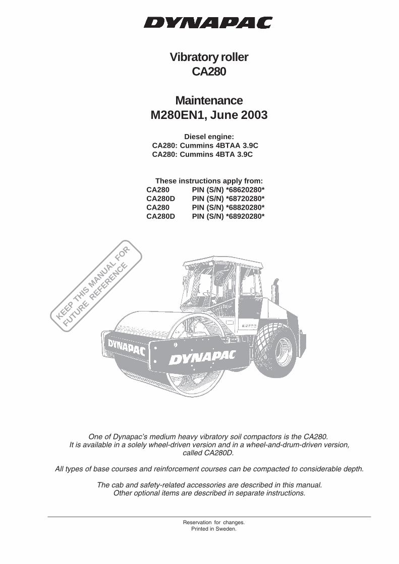
Vibratory rollerCA280
MaintenanceM280EN1, June 2003
Diesel engine:CA280: Cummins 4BTAA 3.9CCA280: Cummins 4BTA 3.9C
These instructions apply from:CA280 PIN (S/N) *68620280*CA280D PIN (S/N) *68720280*CA280 PIN (S/N) *68820280*CA280D PIN (S/N) *68920280*
Reservation for changes.Printed in Sweden.
KEEP THIS
MANUAL F
OR
FUTURE REFERENCE
One of Dynapac’s medium heavy vibratory soil compactors is the CA280.It is available in a solely wheel-driven version and in a wheel-and-drum-driven version,
called CA280D.
All types of base courses and reinforcement courses can be compacted to considerable depth.
The cab and safety-related accessories are described in this manual.Other optional items are described in separate instructions.
2 CA280 M280EN1
CONTENTS
Read the entire manual before starting anyservice work.
Ensure that ventilation (extraction) is adequa-te if the engine is run indoors.
It is essential that the machine is cared for in a propermanner to ensure satisfactory operation. Keep themachine clean to facilitate quick and timely detection ofany leakage, loose bolts and loose connections.
Make a habit each day, before starting up, of checking theroller to detect any leakage or damage. Also check theground underneath the roller, where it is most often easierto detect any leakage.
TAKE CARE OF THE ENVIRONMENTDo not leave behind any oil, fuel or othersubstances that are detrimental to theenvironment.
This manual contains instructions for periodic measuresthat should normally be performed by the operator.
The manufacturer’s instructions noted in theengine manual also apply. This is placed under aseparate flap in the roller’s product folder.
GENERAL
Safety instructions—Personal safety
Special caution—Machine or component damage
WARNING SYMBOLS
CALIFORNIA
Proposition 65 Warning
Diesel engine exhaust and some of itsconstituents are known to the State ofCalifornia to cause cancer, birth defects,and other reproductive harm.
PageLubricants and symbols ................................................... 3Technical specifications ................................................ 4-6Maintenance schedule ..................................................... 7Maintenance measures ................................................ 8, 9Every 10 hours of operation (Daily) .......................... 10-13Every 50 hours of operation (Weekly) ...................... 14-16Every 250 hours of operation (Monthly) .................... 17-21Every 500 hours of operation (Every three months) ...... 22Every 1000 hours of operation (Every six months) .. 23-26Every 2000 hours of operation (Yearly) .................... 27-28Long-term Storage ......................................................... 29Special instructions ........................................................ 30Electrical system, fuses ........................................... 31, 32
3CA280 M280EN1
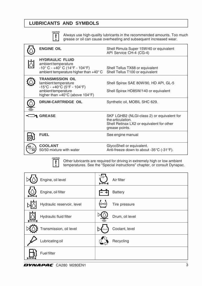
Engine, oil level Air filter
Engine, oil filter Battery
Hydraulic reservoir, level Tire pressure
Hydraulic fluid filter Drum, oil level
Transmission, oil level Coolant, level
Lubricating oil Recycling
Fuel filter
LUBRICANTS AND SYMBOLS
ENGINE OIL Shell Rimula Super 15W/40 or equivalentAPI Service CH-4 (CG-4)
HYDRAULIC FLUIDambient temperature-10° C - +40° C (14°F - 104°F) Shell Tellus TX68 or equivalentambient temperature higher than +40° C Shell Tellus T100 or equivalent
TRANSMISSION OILlambient temperature Shell Spirax SAE 80W/90, HD API, GL-5-15°C - +40°C (5°F - 104°F)ambient temperature Shell Spirax HD85W/140 or equivalenthigher than +40°C (above 104°F)
DRUM-CARTRIDGE OIL Synthetic oil, MOBIL SHC 629.
GREASE SKF LGHB2 (NLGI-class 2) or equivalent forthe articulation.Shell Retinax LX2 or equivalent for othergrease points.
FUEL See engine manual
COOLANT GlycoShell or equivalent.50/50 mixture with water Anti-freeze down to about -35°C (-31°F).
Always use high-quality lubricants in the recommended amounts. Too muchgrease or oil can cause overheating and subsequent increased wear.
Other lubricants are required for driving in extremely high or low ambienttemperatures. See the “Special instructions” chapter, or consult Dynapac.
4 CA280 M280EN1
TECHNICAL SPECIFICATIONS
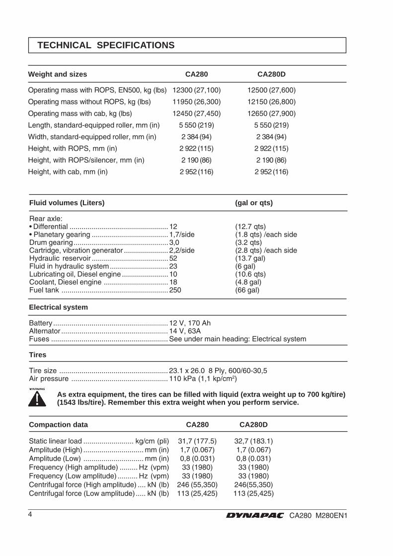
Weight and sizes CA280 CA280D
Operating mass with ROPS, EN500, kg (lbs) 12300 (27,100) 12500 (27,600)
Operating mass without ROPS, kg (lbs) 11950 (26,300) 12150 (26,800)
Operating mass with cab, kg (lbs) 12450 (27,450) 12650 (27,900)
Length, standard-equipped roller, mm (in) 5 550 (219) 5 550 (219)
Width, standard-equipped roller, mm (in) 2 384 (94) 2 384 (94)
Height, with ROPS, mm (in) 2 922 (115) 2 922 (115)
Height, with ROPS/silencer, mm (in) 2 190 (86) 2 190 (86)
Height, with cab, mm (in) 2 952 (116) 2 952 (116)
Fluid volumes (Liters) (gal or qts)
Rear axle:• Differential ................................................. 12 (12.7 qts)• Planetary gearing ...................................... 1,7/side (1.8 qts) /each sideDrum gearing............................................... 3,0 (3.2 qts)Cartridge, vibration generator ...................... 2,2/side (2.8 qts) /each sideHydraulic reservoir ...................................... 52 (13.7 gal)Fluid in hydraulic system............................. 23 (6 gal)Lubricating oil, Diesel engine ....................... 10 (10.6 qts)Coolant, Diesel engine ................................ 18 (4.8 gal)Fuel tank ..................................................... 250 (66 gal)
Electrical system
Battery ......................................................... 12 V, 170 AhAlternator ..................................................... 14 V, 63AFuses .......................................................... See under main heading: Electrical system
Tires
Tire size ...................................................... 23.1 x 26.0 8 Ply, 600/60-30,5Air pressure ................................................ 110 kPa (1,1 kp/cm2)
As extra equipment, the tires can be filled with liquid (extra weight up to 700 kg/tire)(1543 lbs/tire). Remember this extra weight when you perform service.
Compaction data CA280 CA280D
Static linear load ......................... kg/cm (pli) 31,7 (177.5) 32,7 (183.1)Amplitude (High) .............................. mm (in) 1,7 (0.067) 1,7 (0.067)Amplitude (Low) .............................. mm (in) 0,8 (0.031) 0,8 (0.031)Frequency (High amplitude) ......... Hz (vpm) 33 (1980) 33 (1980)Frequency (Low amplitude) .......... Hz (vpm) 33 (1980) 33 (1980)Centrifugal force (High amplitude) .... kN (lb) 246 (55,350) 246(55,350)Centrifugal force (Low amplitude) ..... kN (lb) 113 (25,425) 113 (25,425)
5CA280 M280EN1
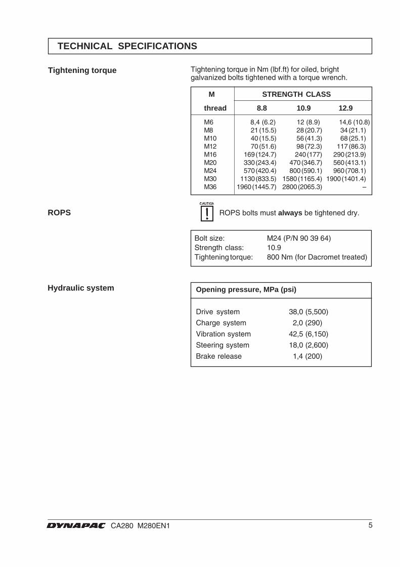
Opening pressure, MPa (psi)
Drive system 38,0 (5,500)
Charge system 2,0 (290)
Vibration system 42,5 (6,150)
Steering system 18,0 (2,600)
Brake release 1,4 (200)
Tightening torque
Hydraulic system
ROPS
M STRENGTH CLASS
thread 8.8 10.9 12.9
M6 8,4 (6.2) 12 (8.9) 14,6 (10.8)M8 21 (15.5) 28 (20.7) 34 (21.1)M10 40 (15.5) 56 (41.3) 68 (25.1)M12 70 (51.6) 98 (72.3) 117 (86.3)M16 169 (124.7) 240 (177) 290 (213.9)M20 330 (243.4) 470 (346.7) 560 (413.1)M24 570 (420.4) 800 (590.1) 960 (708.1)M30 1130 (833.5) 1580 (1165.4) 1900 (1401.4)M36 1960 (1445.7) 2800 (2065.3) –
Tightening torque in Nm (lbf.ft) for oiled, brightgalvanized bolts tightened with a torque wrench.
Bolt size: M24 (P/N 90 39 64)Strength class: 10.9Tightening torque: 800 Nm (for Dacromet treated)
ROPS bolts must always be tightened dry.
TECHNICAL SPECIFICATIONS

6 CA280 M280EN1
CA280 109 90 83
The acoustic values are measured in conformance with the operationcycle described in EU directive 2000/14/EC on EU-equippedmachines, on soft polymer material with vibration switched ON andoperator’s seat in the transport mode.
Acoustic values
Model Guaranteedacousticpower leveldB(A) LwA
Acousticpressure level,operator’s ear(platform)dB(A) LpA
Acousticpressure level,operator’s ear(cab) dB(A)LpA
Noise level can vary when driving on differentcourses and with different seat positions.
The vibration values are measured in conformancewith the operation cycle described in EU directive2000/14/EC on EU-equipped machines, on softpolymer material with vibration switched ON andoperator’s seat in the transport mode.
Operator’s station, vibration, hand/arm(steering wheel/lever):Below limit value.Limit value: <2.5 m/s2.Operator’s station, vibration, entire body(operator’s seat):Below limit value.Limit value: <0.5 m/s2.
Vibrations – Drivers seat(ISO 2631)
Vibration levels may vary when driving ondifferent courses and with different seatpositions.
TECHNICAL SPECIFICATIONS

7CA280 M280EN1
1 2 3 4 5 6 7 8 9 33 10 11 12
26 25 24 23 22 21 20 19 18 17 16 15 14
13
32
31
30
29
28
27
MAINTENANCE SCHEDULE
Fig. 1 Service points
1. Radiator grille2. Oil level, diesel engine3. Fuel filter, fuel pre-filter4. Air filter5. Hydraulic reservoir, sight glass6. Breather filter7. Hydraulic filter, x18. Drain hydraulic reservoir9. Hydraulic fluid, filling10..Fuse box11. Drum cartridge oil filler, x212. Drum gearbox
13. Scrapers14. Drum cartridge oil, level plug, x215. Rubber elements and fastening screws16. Steering joint17. Steering cylinder, x218. Flywheel casing, hydraulic pumps19. Wheel nuts20. Tire pressure21. Rear axle, differential22. Rear axle, planetary gearing, x223. Rear axle suspension, two sides24. Oil filter, diesel engine
25. Draining, fuel tank26. Engine suspension, x427. Feed pump, fuel28. Diesel fuel, filling29. Battery30. Radiator31. Hydraulic fluid cooler32. Drive belts, cooling, alternator33. Forward/Reverse lever

8 CA280 M280EN1
Perform periodic maintenance measures daily, weekly,etc. whichever comes first, or after the stipulated hoursof operation.
Remove all dirt before filling, when checkingoils and fuel, and when lubricating with oil orgrease.
The manufacturer’s instructions noted in theengine manual also apply.
MAINTENANCE MEASURES
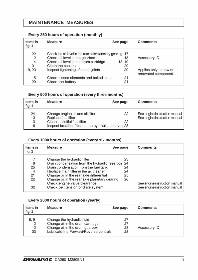
Items in Measure See page Commentsfig. 1
Before starting up13 Check the scraper setting 101 Check for free circulation of cooling air 11
30 Check coolant level 11 See engine instruction manual2 Check oil level in the engine 12 See engine instruction manual
28 Refuel 125 Check the hydraulic reservoir level 12
Test the brakes 13
Every 10 hours of operation (daily)
Items in Measure See page Commentsfig. 1
4 Check that hoses and connections are tight 146 Control/clean the filter element in the air cleaner 14 Replace as required
16 Grease the steering joints 1517 Grease the steering cylinder brackets 1519 Check tightness of the wheel nuts 1620 Check the tire pressure 16
After the first 50 hours of operation change only the drum oil and all the oil filters.
Every 50 hours of operation (weekly)
9CA280 M280EN1
MAINTENANCE MEASURES
Items in Measure See page Commentsfig. 1
22 Check the oil level in the rear axle/planetary gearing 1712 Check oil level in the gearbox 18 Accessory D14 Check oil level in the drum cartridge 18, 1931 Clean the coolers 20
19, 23 Inspect tightening of bolted joints 20 Applies only to new orrenovated component.
15 Check rubber elements and bolted joints 2129 Check the battery 21
Every 250 hours of operation (monthly)
Items in Measure See page Commentsfig. 1
7 Change the hydraulic filter 238 Drain condensation from the hydraulic reservoir 24
25 Drain condensation from the fuel tank 244 Replace main filter in the air cleaner 24
21 Change oil in the rear axle differential 2522 Change oil in the rear axle planetary gearing 26
Check engine valve clearance See engine instruction manual32 Check belt tension of drive system See engine instruction manual
Every 1000 hours of operation (every six months)
Items in Measure See page Commentsfig. 1
8, 9 Change the hydraulic fluid 2712 Change oil in the drum cartridge 2712 Change oil in the drum gearbox 28 Accessory D33 Lubricate the Forward/Reverse controls 28
Every 2000 hours of operation (yearly)
Items in Measure See page Commentsfig. 1
24 Change engine oil and oil filter 22 See engine instruction manual3 Replace fuel filter See engine instruction manual3 Clean the initial fuel filter 226 Inspect breather filter on the hydraulic reservoir 23
Every 500 hours of operation (every three months)
10 CA280 M280EN1
2
1
1 2
2 1 1 2
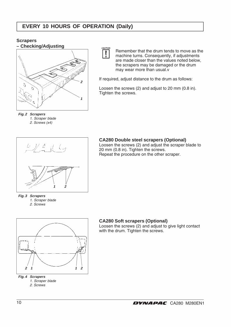
CA280 Soft scrapers (Optional)Loosen the screws (2) and adjust to give light contactwith the drum. Tighten the screws.
Fig. 4 Scrapers1. Scraper blade2. Screws
EVERY 10 HOURS OF OPERATION (Daily)
Remember that the drum tends to move as themachine turns. Consequently, if adjustmentsare made closer than the values noted below,the scrapers may be damaged or the drummay wear more than usual.v
If required, adjust distance to the drum as follows:
Loosen the screws (2) and adjust to 20 mm (0.8 in).Tighten the screws.
Scrapers– Checking/Adjusting
Fig. 2 Scrapers1. Scraper blade2. Screws (x4)
Fig. 3 Scrapers1. Scraper blade2. Screws
CA280 Double steel scrapers (Optional)Loosen the screws (2) and adjust the scraper blade to20 mm (0.8 in). Tighten the screws.Repeat the procedure on the other scraper.
11CA280 M280EN1
1 3
2
2
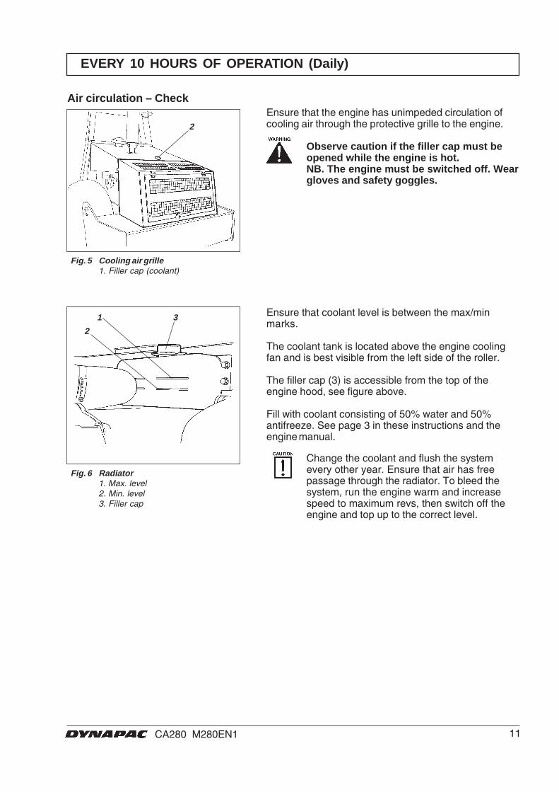
Ensure that the engine has unimpeded circulation ofcooling air through the protective grille to the engine.
Observe caution if the filler cap must beopened while the engine is hot.NB. The engine must be switched off. Weargloves and safety goggles.
Air circulation – Check
Fig. 5 Cooling air grille1. Filler cap (coolant)
EVERY 10 HOURS OF OPERATION (Daily)
Fig. 6 Radiator1. Max. level2. Min. level3. Filler cap
Ensure that coolant level is between the max/minmarks.
The coolant tank is located above the engine coolingfan and is best visible from the left side of the roller.
The filler cap (3) is accessible from the top of theengine hood, see figure above.
Fill with coolant consisting of 50% water and 50%antifreeze. See page 3 in these instructions and theengine manual.
Change the coolant and flush the systemevery other year. Ensure that air has freepassage through the radiator. To bleed thesystem, run the engine warm and increasespeed to maximum revs, then switch off theengine and top up to the correct level.
12 CA280 M280EN1
1
1
2
1
2
Hydraulic reservoir– Checking the fluid level
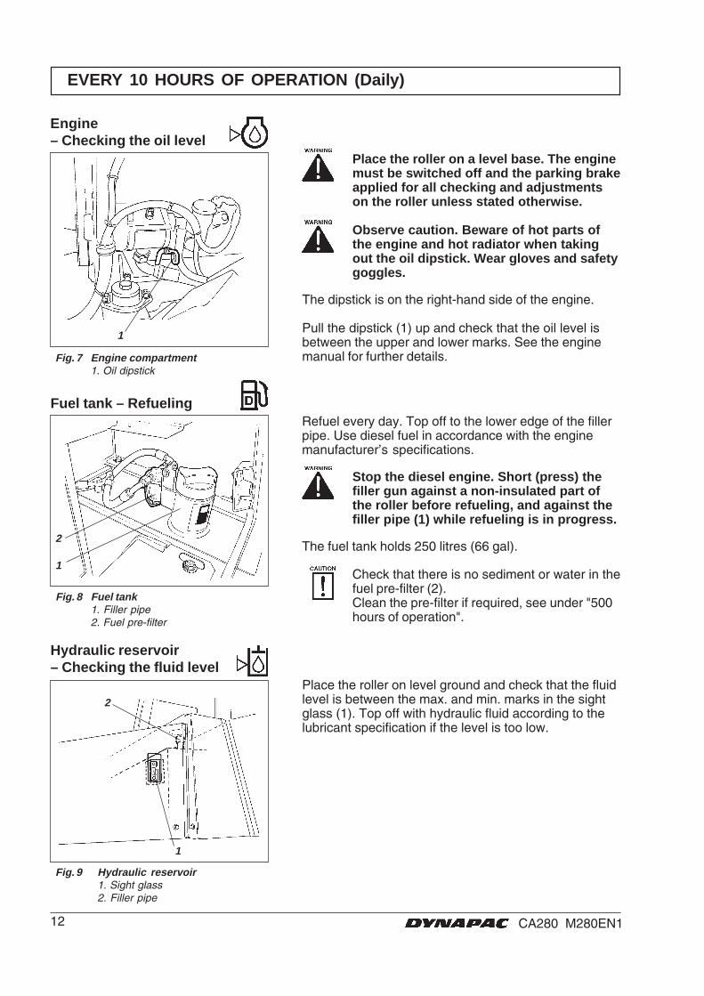
Refuel every day. Top off to the lower edge of the fillerpipe. Use diesel fuel in accordance with the enginemanufacturer’s specifications.
Stop the diesel engine. Short (press) thefiller gun against a non-insulated part ofthe roller before refueling, and against thefiller pipe (1) while refueling is in progress.
The fuel tank holds 250 litres (66 gal).
EVERY 10 HOURS OF OPERATION (Daily)
Engine– Checking the oil level
Fig. 7 Engine compartment1. Oil dipstick
Place the roller on a level base. The enginemust be switched off and the parking brakeapplied for all checking and adjustmentson the roller unless stated otherwise.
Observe caution. Beware of hot parts ofthe engine and hot radiator when takingout the oil dipstick. Wear gloves and safetygoggles.
The dipstick is on the right-hand side of the engine.
Pull the dipstick (1) up and check that the oil level isbetween the upper and lower marks. See the enginemanual for further details.
Fig. 8 Fuel tank1. Filler pipe2. Fuel pre-filter
Fuel tank – Refueling
Check that there is no sediment or water in thefuel pre-filter (2).Clean the pre-filter if required, see under "500hours of operation".
Fig. 9 Hydraulic reservoir1. Sight glass2. Filler pipe
Place the roller on level ground and check that the fluidlevel is between the max. and min. marks in the sightglass (1). Top off with hydraulic fluid according to thelubricant specification if the level is too low.
13CA280 M280EN1
13
2
EVERY 10 HOURS OF OPERATION (Daily)
Brakes – Check
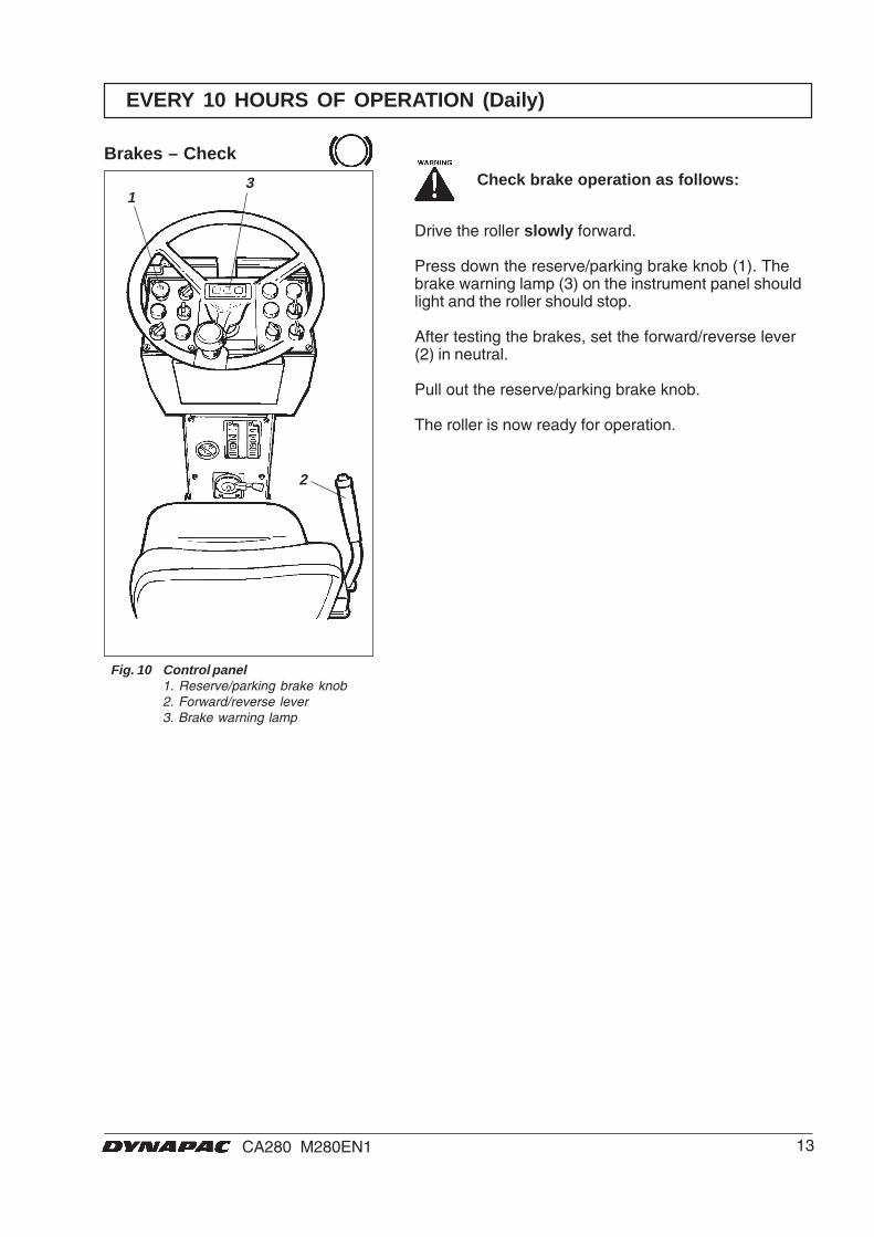
Fig. 10 Control panel1. Reserve/parking brake knob2. Forward/reverse lever3. Brake warning lamp
Check brake operation as follows:
Drive the roller slowly forward.
Press down the reserve/parking brake knob (1). Thebrake warning lamp (3) on the instrument panel shouldlight and the roller should stop.
After testing the brakes, set the forward/reverse lever(2) in neutral.
Pull out the reserve/parking brake knob.
The roller is now ready for operation.

14 CA280 M280EN1
2 3
1 4 5
4
EVERY 50 HOURS OF OPERATION (Weekly)
Air cleaner– Checking/cleaning
Main filter – Cleaning withcompressed air
Fig. 12 Main filter
Fig. 11 Air cleaner1. Locking braces2. Cover3. Main filter4. Backup filter5. Filter housing
Place the roller on a level surface. Switchthe engine off and push in the reserve/parking brake knob for all checking andadjustments on the roller, unless otherwisespecified.
Replace or clean the main filter of the aircleaner when the warning lamp on the instru-ment panel lights at full engine revs.
Release the three locking braces (1) and pull off thecover (2) and take out the main filter (3).
Do not remove the backup filter (4).
Replace the backup filter with a new one after everyfifth replacement or cleaning of the main filter. Thesecondary filter cannot be cleaned.
To change the backup filter (4), pull the old filter out ofits holder, insert a new one and reassemble the aircleaner in the reverse order in relation to theinstructions in the figure above.
Fig. 13 Air filter4. Backup filter
Backup filter– Replacement
To clean the main filter, blow up and down along thepaper pleats with compressed air at maximum 5 bar(72 psi) pressure.
Hold the nozzle at least 2–3 cm (0.8-1.2 in) from thepaper pleats to avoid tearing the paper.
Wear protective goggles when workingwith compressed air.
Wipe the inside of the cover (2) and filter housing (5).
Check that the hose clamps between the filterhousing and suction hose are tight and that thehoses are intact. Inspect all hoses all the wayto the engine.
Change the main filter at the latest after 5cleanings.
15CA280 M280EN1
1
1
2
3 4
1
Steering cylinders– Lubrication
Steering joint– Lubrication
Steering joint/Steering cylinders– Lubrication
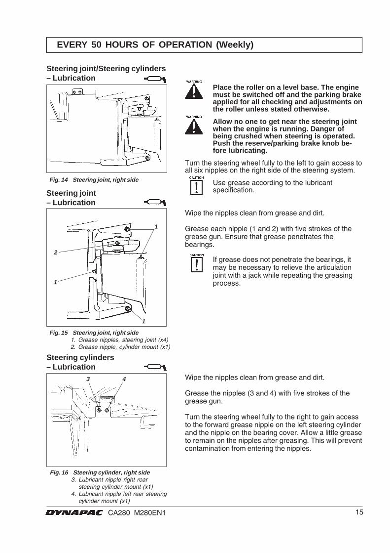
Fig. 14 Steering joint, right side
Place the roller on a level base. The enginemust be switched off and the parking brakeapplied for all checking and adjustments onthe roller unless stated otherwise.
Allow no one to get near the steering jointwhen the engine is running. Danger ofbeing crushed when steering is operated.Push the reserve/parking brake knob be-fore lubricating.
Turn the steering wheel fully to the left to gain access toall six nipples on the right side of the steering system.
Use grease according to the lubricantspecification.
Fig. 16 Steering cylinder, right side3. Lubricant nipple right rear
steering cylinder mount (x1)4. Lubricant nipple left rear steering
cylinder mount (x1)
Fig. 15 Steering joint, right side1. Grease nipples, steering joint (x4)2. Grease nipple, cylinder mount (x1)
EVERY 50 HOURS OF OPERATION (Weekly)
Wipe the nipples clean from grease and dirt.
Grease the nipples (3 and 4) with five strokes of thegrease gun.
Turn the steering wheel fully to the right to gain accessto the forward grease nipple on the left steering cylinderand the nipple on the bearing cover. Allow a little greaseto remain on the nipples after greasing. This will preventcontamination from entering the nipples.
Wipe the nipples clean from grease and dirt.
Grease each nipple (1 and 2) with five strokes of thegrease gun. Ensure that grease penetrates thebearings.
If grease does not penetrate the bearings, itmay be necessary to relieve the articulationjoint with a jack while repeating the greasingprocess.
16 CA280 M280EN1
12
EVERY 50 HOURS OF OPERATION (Weekly)
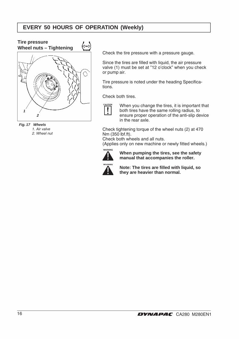
Tire pressureWheel nuts – Tightening
Check the tire pressure with a pressure gauge.
Since the tires are filled with liquid, the air pressurevalve (1) must be set at ”12 o’clock” when you checkor pump air.
Tire pressure is noted under the heading Specifica-tions.
Check both tires.
When you change the tires, it is important thatboth tires have the same rolling radius, toensure proper operation of the anti-slip devicein the rear axle.
Check tightening torque of the wheel nuts (2) at 470Nm (350 lbf.ft).Check both wheels and all nuts.(Applies only on new machine or newly fitted wheels.)
When pumping the tires, see the safetymanual that accompanies the roller.
Note: The tires are filled with liquid, sothey are heavier than normal.
Fig. 17 Wheels1. Air valve2. Wheel nut

17CA280 M280EN1
1
1
1
EVERY 250 HOURS OF OPERATION (Monthly)
Rear axle differential– Checking the oil level
Fig. 18 Level check—differential housing1. Level/Filler plug
Rear axle planetary gearing– Checking the oil level
Fig. 19 Level check- planetary gearing, std1. Level/Filler plug
Place the roller on a level base. The enginemust be switched off and the parking brakeapplied for all checking and adjustmentson the roller unless stated otherwise.
Never work under the roller with the engi-ne running. Park on a level surface. Blockthe wheels securely.
Wipe clean, remove the level plug (1) and check thatthe oil level reaches the lower edge of the plug hole.Top off to the right level if the level is low. Use trans-mission oil. See lubricant specification.
Position the roller with the plug (1) in the planetarygearing at 9 o'clock.
Wipe clean, remove the level plug and check that the oillevel reaches the lower edge of the plug hole. Top off tothe right level if the level is low. Use transmission oil.See lubricant specification.
Check the oil level in the same way in the other plan-etary gearing of the rear axle.
Fig. 20 Level check- planetary gearing, accessory1. Level/Filler plug

18 CA280 M280EN1
1
1
2
3
1
2
3
EVERY 250 HOURS OF OPERATION (Monthly)
Drum cartridge– Checking the oil level
Position the machine level so that the indicator pin (1)on the inside of the drum is aligned with the top of thedrum frame.
Fig. 22 Left side of drum1. Indicator pin
Fig. 23 Roller, right-hand side1. Filler plug2. Drain plug3. Level plug
Drum cartridge– Checking the oil level
Wipe the filling plug and level plug clean from dirt.Unscrew the filling plug (1).
Fig. 21 Level check - drum gearbox1. Level plug2. Filler plug3. Drain plug
Drum gearbox– Checking the oil level
Position the roller with the filler plugs (2) straight up.
Wipe clean round the level plug (1) and unscrew it.
Ensure that the oil level reaches up to the lower edge ofthe plug hole.
Top off to the right level if the level is low. Use trans-mission oil according to the lubricant specification.
Clean and screw in the plugs tight.
19CA280 M280EN1
1
32
EVERY 250 HOURS OF OPERATION (Monthly)
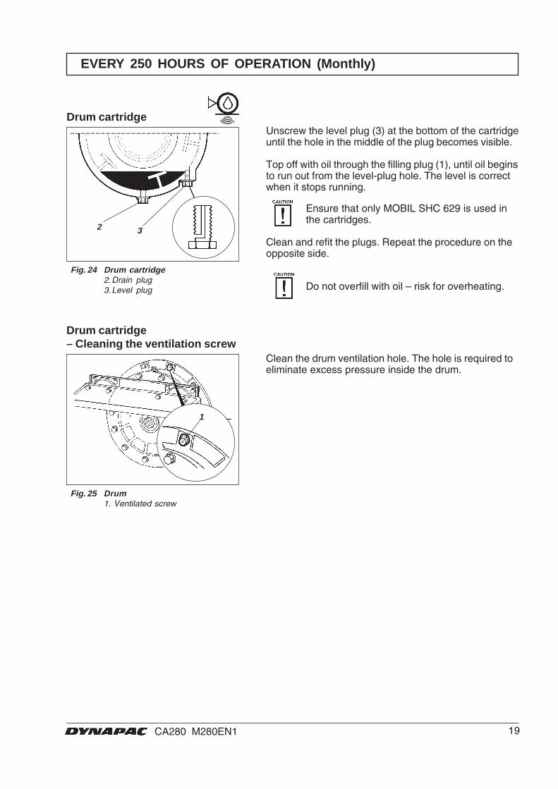
Fig. 25 Drum1. Ventilated screw
Drum cartridge– Cleaning the ventilation screw
Clean the drum ventilation hole. The hole is required toeliminate excess pressure inside the drum.
Unscrew the level plug (3) at the bottom of the cartridgeuntil the hole in the middle of the plug becomes visible.
Top off with oil through the filling plug (1), until oil beginsto run out from the level-plug hole. The level is correctwhen it stops running.
Ensure that only MOBIL SHC 629 is used inthe cartridges.
Clean and refit the plugs. Repeat the procedure on theopposite side.
Do not overfill with oil – risk for overheating.
Drum cartridge
Fig. 24 Drum cartridge2.Drain plug3.Level plug

20 CA280 M280EN1
1
2
32
1
4
12
3
EVERY 250 HOURS OF OPERATION (Monthly)
Check all rubber elements (1), replace all of theelements if more than 25% of them on one side of thedrum are cracked deeper than 10–15 mm (0.4-0.6 in).
Use the blade of a knife or pointed object to assistwhen checking.
Ensure that the fastening screws (2) are tightened.
Fig. 28 Drum, vibration side1. Rubber element2. Fastening screws
Rubber elements and fasteningscrews – Check
Fig. 26 Hydraulic cooler1. Water cooler2. Hydraulic fluid cooler3. Intercooler
Open the engine cover to gain access to the water andhydraulic coolers, and the intercooler.
Ensure that the flow of air through the coolers (1), (2)and (3) is unobstructed.
Clean a dirty radiator using compressed air or a high-pressure water jet. Blow or wash the radiator in theopposite direction to that of the cooling air.
Take care when using a high-pressure waterjet; do not hold the nozzle too near the cooler.The cooler may otherwise be damaged.
Wear protective goggles when workingwith compressed air or high-pressurewater jet.
Coolers– Checking/cleaning
Bolted joints– Tightening check
Fig. 27 Right side of machine1. Steering pump2. Rear axle3. Engine suspension4. Wheel nuts
Steering pump against diesel engine (1) 38 Nm(28 ft.lbs).
Rear axle suspension (2) 330 Nm (243 ft.lbs) oiled.
Engine suspension (3). Check that all M12 bolts (x20),are tightened (20 off), 78 Nm (57 ft.lbs).
Wheel nuts (4). Check that all nuts are tightened, 470Nm (347 ft.lbs), oiled.
(The above applies only to new or replacedcomponents.)
21CA280 M280EN1
1
2
3
10 mm
1 2 3 1
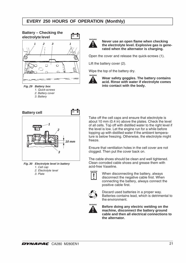
Take off the cell caps and ensure that electrolyte isabout 10 mm (0.4 in) above the plates. Check the levelof all cells. Top off with distilled water to the right level ifthe level is low. Let the engine run for a while beforetopping up with distilled water if the ambient tempera-ture is below freezing. Otherwise, the electrolyte mightfreeze.
Ensure that ventilation holes in the cell cover are notclogged. Then put the cover back on.
The cable shoes should be clean and well tightened.Clean corroded cable shoes and grease them withacid-free Vaseline.
When disconnecting the battery, alwaysdisconnect the negative cable first. Whenconnecting the battery, always connect thepositive cable first.
Discard used batteries in a proper way.Batteries contains lead, which is detrimental tothe environment.
Before doing any electric welding on themachine, disconnect the battery groundcable and then all electrical connections tothe alternator.
Battery cell
Fig. 30 Electrolyte level in battery1. Cell cap2. Electrolyte level3. Plate
EVERY 250 HOURS OF OPERATION (Monthly)
Never use an open flame when checkingthe electrolyte level. Explosive gas is gene-rated when the alternator is charging.
Open the cover and release the quick-screws (1).
Lift the battery cover (2).
Wipe the top of the battery dry.
Wear safety goggles. The battery containsacid. Rinse with water if electrolyte comesinto contact with the body.
Battery – Checking theelectrolyte level
Fig. 29 Battery box1. Quick-screws2. Battery cover3. Battery
22 CA280 M280EN1
3 2 1
2 1
EVERY 500 HOURS OF OPERATION (Every three months)
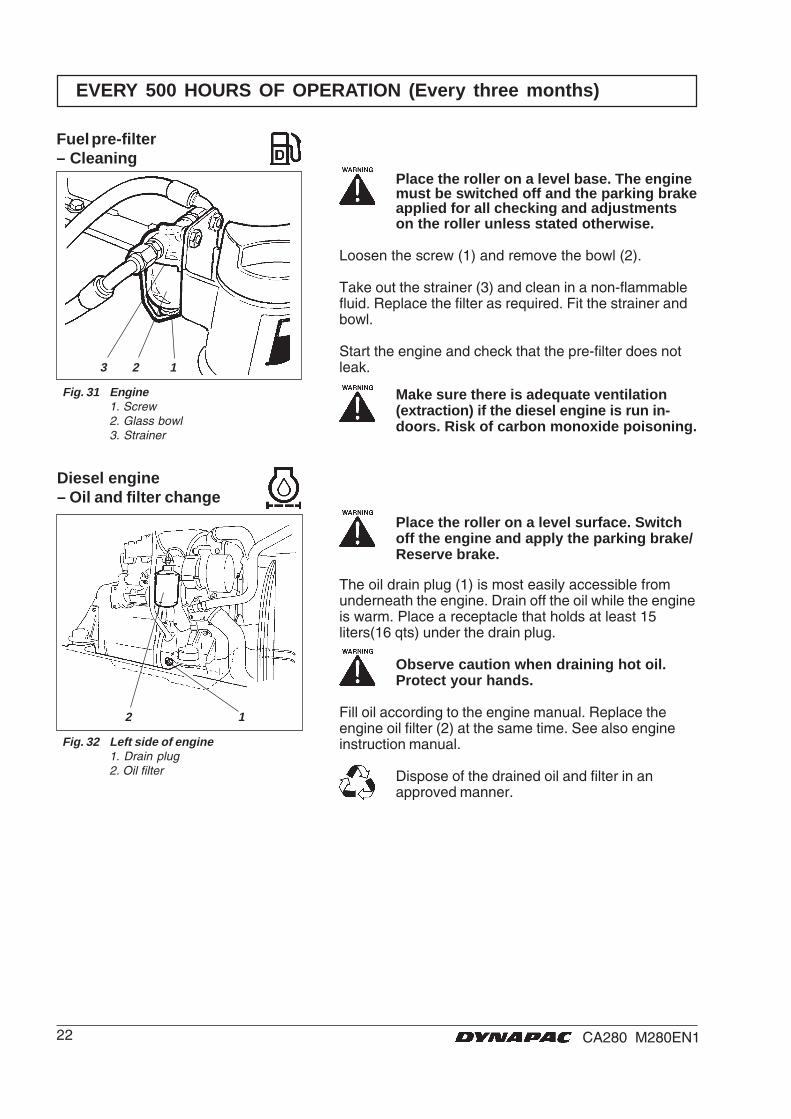
Fig. 31 Engine1. Screw2. Glass bowl3. Strainer
Fuel pre-filter– Cleaning
Place the roller on a level base. The enginemust be switched off and the parking brakeapplied for all checking and adjustmentson the roller unless stated otherwise.
Loosen the screw (1) and remove the bowl (2).
Take out the strainer (3) and clean in a non-flammablefluid. Replace the filter as required. Fit the strainer andbowl.
Start the engine and check that the pre-filter does notleak.
Make sure there is adequate ventilation(extraction) if the diesel engine is run in-doors. Risk of carbon monoxide poisoning.
Fig. 32 Left side of engine1. Drain plug2. Oil filter
Diesel engine– Oil and filter change
Place the roller on a level surface. Switchoff the engine and apply the parking brake/Reserve brake.
The oil drain plug (1) is most easily accessible fromunderneath the engine. Drain off the oil while the engineis warm. Place a receptacle that holds at least 15liters(16 qts) under the drain plug.
Observe caution when draining hot oil.Protect your hands.
Fill oil according to the engine manual. Replace theengine oil filter (2) at the same time. See also engineinstruction manual.
Dispose of the drained oil and filter in anapproved manner.
23CA280 M280EN1
3
2
1
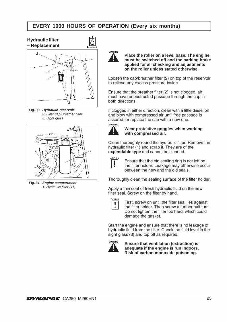
Place the roller on a level base. The enginemust be switched off and the parking brakeapplied for all checking and adjustmentson the roller unless stated otherwise.
Loosen the cap/breather filter (2) on top of the reservoirto relieve any excess pressure inside.
Ensure that the breather filter (2) is not clogged, airmust have unobstructed passage through the cap inboth directions.
If clogged in either direction, clean with a little diesel oiland blow with compressed air until free passage isassured, or replace the cap with a new one.
Wear protective goggles when workingwith compressed air.
Clean thoroughly round the hydraulic filter. Remove thehydraulic filter (1) and scrap it. They are of theexpendable type and cannot be cleaned.
Ensure that the old sealing ring is not left onthe filter holder. Leakage may otherwise occurbetween the new and the old seals.
Thoroughly clean the sealing surface of the filter holder.
Apply a thin coat of fresh hydraulic fluid on the newfilter seal. Screw on the filter by hand.
First, screw on until the filter seal lies againstthe filter holder. Then screw a further half turn.Do not tighten the filter too hard, which coulddamage the gasket.
Start the engine and ensure that there is no leakage ofhydraulic fluid from the filter. Check the fluid level in thesight glass (3) and top off as required.
Ensure that ventilation (extraction) isadequate if the engine is run indoors.Risk of carbon monoxide poisoning.
Fig. 34 Engine compartment1. Hydraulic filter (x1)
Fig. 33 Hydraulic reservoir2. Filler cap/Breather filter3. Sight glass
EVERY 1000 HOURS OF OPERATION (Every six months)
Hydraulic filter– Replacement
24 CA280 M280EN1
1
2
1
2 3
1 4 5
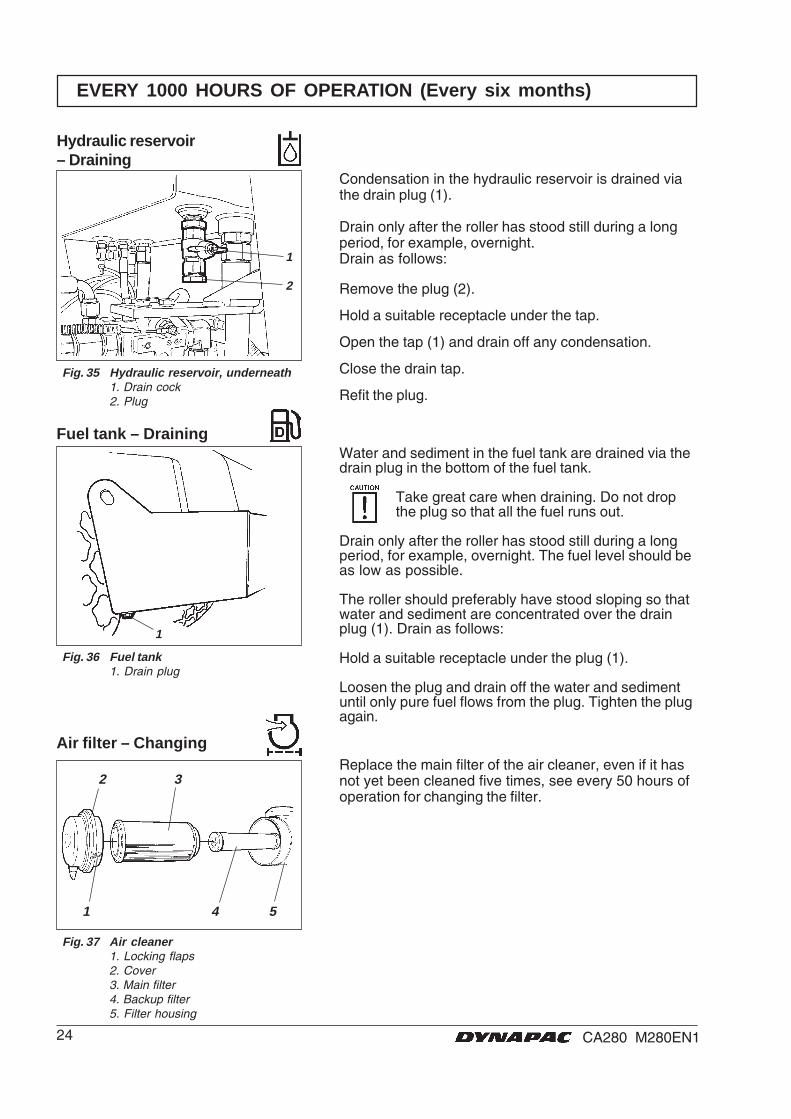
Water and sediment in the fuel tank are drained via thedrain plug in the bottom of the fuel tank.
Take great care when draining. Do not dropthe plug so that all the fuel runs out.
Drain only after the roller has stood still during a longperiod, for example, overnight. The fuel level should beas low as possible.
The roller should preferably have stood sloping so thatwater and sediment are concentrated over the drainplug (1). Drain as follows:
Hold a suitable receptacle under the plug (1).
Loosen the plug and drain off the water and sedimentuntil only pure fuel flows from the plug. Tighten the plugagain.
EVERY 1000 HOURS OF OPERATION (Every six months)
Fig. 36 Fuel tank1. Drain plug
Fuel tank – Draining
Replace the main filter of the air cleaner, even if it hasnot yet been cleaned five times, see every 50 hours ofoperation for changing the filter.
Fig. 37 Air cleaner1. Locking flaps2. Cover3. Main filter4. Backup filter5. Filter housing
Air filter – Changing
Hydraulic reservoir– Draining
Condensation in the hydraulic reservoir is drained viathe drain plug (1).
Drain only after the roller has stood still during a longperiod, for example, overnight.Drain as follows:
Remove the plug (2).
Hold a suitable receptacle under the tap.
Open the tap (1) and drain off any condensation.
Close the drain tap.
Refit the plug.
Fig. 35 Hydraulic reservoir, underneath1. Drain cock2. Plug
25CA280 M280EN1
1
2
EVERY 1000 HOURS OF OPERATION (Every six months)
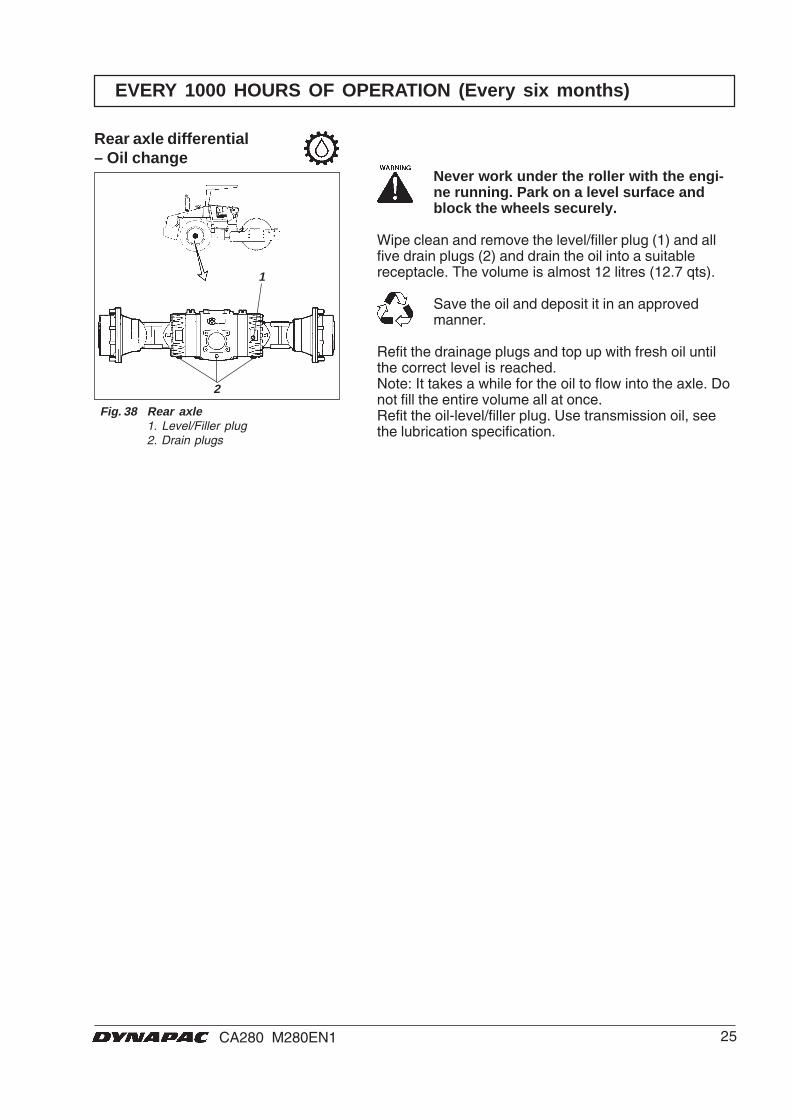
Fig. 38 Rear axle1. Level/Filler plug2. Drain plugs
Rear axle differential– Oil change
Never work under the roller with the engi-ne running. Park on a level surface andblock the wheels securely.
Wipe clean and remove the level/filler plug (1) and allfive drain plugs (2) and drain the oil into a suitablereceptacle. The volume is almost 12 litres (12.7 qts).
Save the oil and deposit it in an approvedmanner.
Refit the drainage plugs and top up with fresh oil untilthe correct level is reached.Note: It takes a while for the oil to flow into the axle. Donot fill the entire volume all at once.Refit the oil-level/filler plug. Use transmission oil, seethe lubrication specification.
26 CA280 M280EN1
1
1
1
1
Std.
Std.
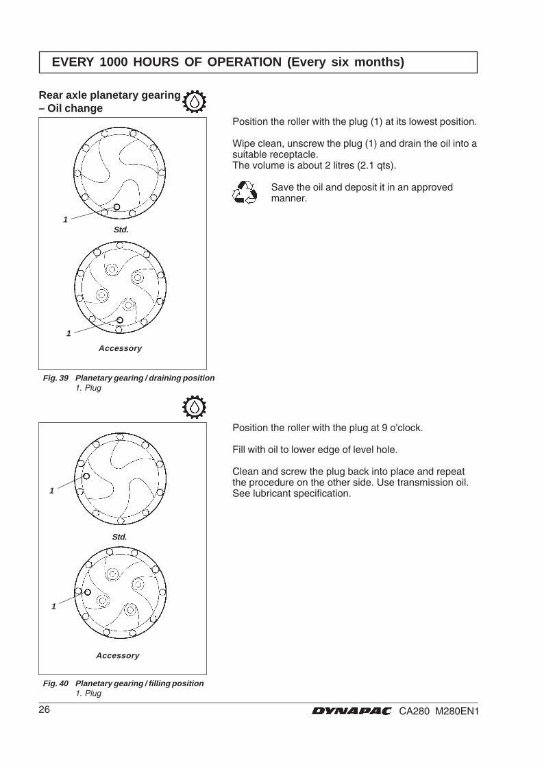
Rear axle planetary gearing– Oil change
Fig. 39 Planetary gearing / draining position1. Plug
Fig. 40 Planetary gearing / filling position1. Plug
EVERY 1000 HOURS OF OPERATION (Every six months)
Position the roller with the plug (1) at its lowest position.
Wipe clean, unscrew the plug (1) and drain the oil into asuitable receptacle.The volume is about 2 litres (2.1 qts).
Save the oil and deposit it in an approvedmanner.
Position the roller with the plug at 9 o'clock.
Fill with oil to lower edge of level hole.
Clean and screw the plug back into place and repeatthe procedure on the other side. Use transmission oil.See lubricant specification.
Accessory
Accessory
27CA280 M280EN1
1
1
2
3
1
2
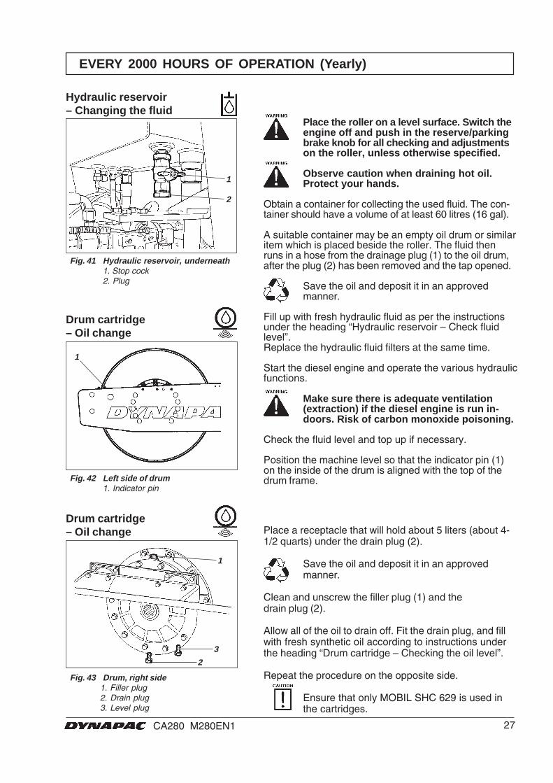
Hydraulic reservoir– Changing the fluid
Fig. 41 Hydraulic reservoir, underneath1. Stop cock2. Plug
EVERY 2000 HOURS OF OPERATION (Yearly)
Drum cartridge– Oil change
Fig. 43 Drum, right side1. Filler plug2. Drain plug3. Level plug
Place a receptacle that will hold about 5 liters (about 4-1/2 quarts) under the drain plug (2).
Save the oil and deposit it in an approvedmanner.
Clean and unscrew the filler plug (1) and thedrain plug (2).
Allow all of the oil to drain off. Fit the drain plug, and fillwith fresh synthetic oil according to instructions underthe heading “Drum cartridge – Checking the oil level”.
Repeat the procedure on the opposite side.
Ensure that only MOBIL SHC 629 is used inthe cartridges.
Place the roller on a level surface. Switch theengine off and push in the reserve/parkingbrake knob for all checking and adjustmentson the roller, unless otherwise specified.
Observe caution when draining hot oil.Protect your hands.
Obtain a container for collecting the used fluid. The con-tainer should have a volume of at least 60 litres (16 gal).
A suitable container may be an empty oil drum or similaritem which is placed beside the roller. The fluid thenruns in a hose from the drainage plug (1) to the oil drum,after the plug (2) has been removed and the tap opened.
Save the oil and deposit it in an approvedmanner.
Fill up with fresh hydraulic fluid as per the instructionsunder the heading “Hydraulic reservoir – Check fluidlevel”.Replace the hydraulic fluid filters at the same time.
Start the diesel engine and operate the various hydraulicfunctions.
Make sure there is adequate ventilation(extraction) if the diesel engine is run in-doors. Risk of carbon monoxide poisoning.
Check the fluid level and top up if necessary.
Position the machine level so that the indicator pin (1)on the inside of the drum is aligned with the top of thedrum frame.Fig. 42 Left side of drum
1. Indicator pin
Drum cartridge– Oil change
28 CA280 M280EN1
2
1
3
2
1
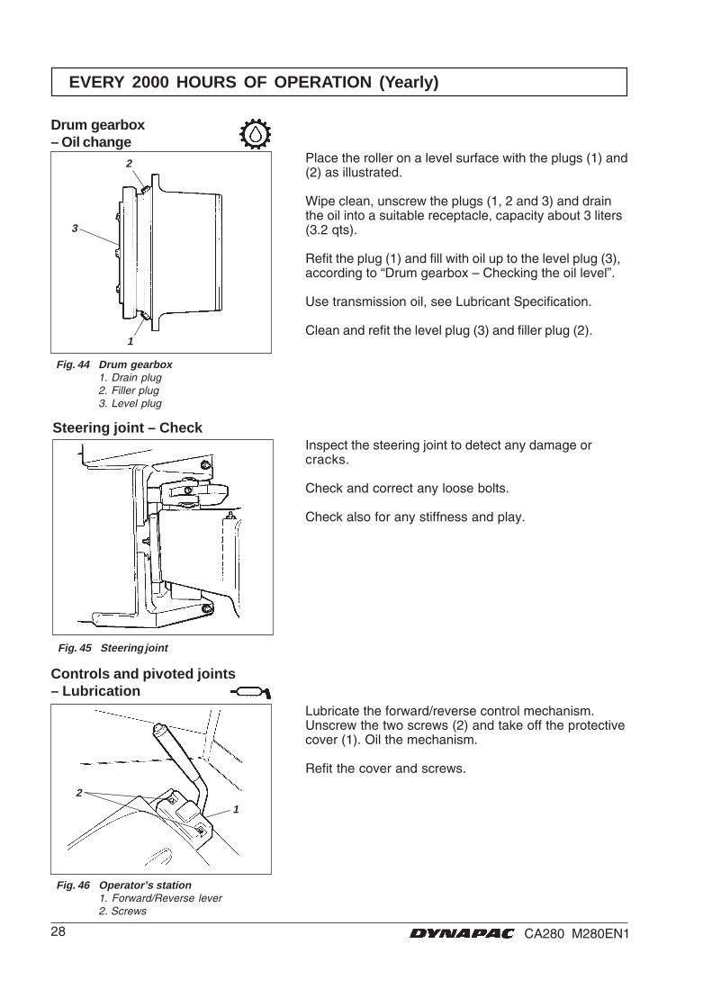
EVERY 2000 HOURS OF OPERATION (Yearly)
Drum gearbox– Oil change
Fig. 44 Drum gearbox1. Drain plug2. Filler plug3. Level plug
Place the roller on a level surface with the plugs (1) and(2) as illustrated.
Wipe clean, unscrew the plugs (1, 2 and 3) and drainthe oil into a suitable receptacle, capacity about 3 liters(3.2 qts).
Refit the plug (1) and fill with oil up to the level plug (3),according to “Drum gearbox – Checking the oil level”.
Use transmission oil, see Lubricant Specification.
Clean and refit the level plug (3) and filler plug (2).
Steering joint – CheckInspect the steering joint to detect any damage orcracks.
Check and correct any loose bolts.
Check also for any stiffness and play.
Fig. 45 Steering joint
Fig. 46 Operator’s station1. Forward/Reverse lever2. Screws
Controls and pivoted joints– Lubrication
Lubricate the forward/reverse control mechanism.Unscrew the two screws (2) and take off the protectivecover (1). Oil the mechanism.
Refit the cover and screws.
29CA280 M280EN1
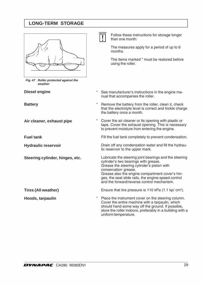
LONG-TERM STORAGE
* See manufacturer’s instructions in the engine ma-nual that accompanies the roller.
* Remove the battery from the roller, clean it, checkthat the electrolyte level is correct and trickle chargethe battery once a month.
* Cover the air cleaner or its opening with plastic ortape. Cover the exhaust opening. This is necessaryto prevent moisture from entering the engine.
Fill the fuel tank completely to prevent condensation.
Drain off any condensation water and fill the hydrau-lic reservoir to the upper mark.
Lubricate the steering joint bearings and the steeringcylinder’s two bearings with grease.Grease the steering cylinder’s piston withconservation grease.Grease also the engine compartment cover’s hin-ges, the seat slide rails, the engine-speed controland the forward/reverse control mechanism.
Ensure that tire pressure is 110 kPa (1.1 kp/ cm2).
* Place the instrument cover on the steering column.Cover the entire machine with a tarpaulin, whichshould hand some way off the ground. If possible,store the roller indoors, preferably in a building with auniform temperature.
Follow these instructions for storage longerthan one month:
The measures apply for a period of up to 6months.
The items marked * must be restored beforeusing the roller.
Battery
Diesel engine
Air cleaner, exhaust pipe
Fuel tank
Hydraulic reservoir
Steering cylinder, hinges, etc.
Hoods, tarpaulin
Tires (All weather)
Fig. 47 Roller protected against theweather
30 CA280 M280EN1
SPECIAL INSTRUCTIONS
The temperature limits apply to standard versions ofthe roller.
Rollers that are fitted with additional equipment, suchas noise suppression, etc., may require extra observa-tion in the higher temperature ranges.
When washing the machine, do not direct thejet of water directly at the fuel or hydraulic fluidtank covers. This is particularly importantwhen using a high-pressure washing unit.
Do not spray water directly on electric components orthe instrument panel. Put a plastic bag over the fillercap of the fuel tank and secure with a rubber band.This will prevent water from entering the venting hole inthe filler cap. This could otherwise cause operationaldisturbance, for example, a clogged filter.
In the event of fire in the machine, use an ABE-powderfire extinguisher if possible. A BE type carbon dioxidefire extinguisher may also be used.
If the roller is equipped with a protective structure(ROPS, Roll Over Protective Structure), or protectivecab, never subject the structure or cab to welding ordrilling. Never attempt to repair a damaged structure orcab; they must be replaced with new ones.
When using an auxiliary battery to assist starting,always connect the positive terminal of the auxiliarybattery to the positive terminal of the roller battery, andnegative to negative.
Starting aid
Protective structure (ROPS)
Fire fighting
High-pressure washing
Temperature
Standard oils and otherrecommended fluids
Higher ambient temperaturemax. +50°C (122°F)
Upon delivery from the factory, the various systemsand components are filled with the oils specified seelubricant specification and they can be used at ambienttemperatures from -10°C to +40°C (14°F - 104°F).
A maximum temperature of +35°C (95°F)applies for biological hydraulic fluid.
When operating in hotter ambient temperatures, but upto max. +50°C (122°F), the following instructions apply:
The diesel engine can handle this temperature with thestandard oil, but the following oils must be used in theother components:Hydraulic system with mineral fluid: Shell Tellus TX100or corresponding.Other components using transmission oil:Shell Spirax HD 85W/140 or corresponding.

31CA280 M280EN1
2 2
1
5 6 7 8
3 4
ELECTRICAL SYSTEM, FUSES
The electrical regulating and control system isprotected by fuses and relays. The number depends onhow much additional equipment the machine isprepared for.
The two fuse boxes (3, 4) and the relays (5, 6, 7, 8) arelocated behind the lower instrument plate, which isremoved by unscrewing the screws (1 and 2).
The machine is equipped with a 12 V electrical systemand an alternator.
Connect the battery to the correct polarity(– to ground). The cable between batteryand alternator must not be disconnectedwhen the engine is running.Fig. 48 Instrument panel
1. Screws2. Screws
Fuses and relays
Fig. 49 Instrument panel3,4. Fuse box
5. VBS relay6. Main relay7. Hourmeter relay8. Lights relay
= Optional
Fuse boxes in steering column
Fig. 50 Fuse box, left side7.5A 1. Hourmeter7.5A 2. VBS relay7.5A 3. Warning lamp7.5A 4. Horn, Fuel gauge7.5A 5. -10A 6. Front wiper, cab
Fig. shows the rating and function of the different fuses.All fuses are flat pin fuses.
Fuse box, right side7.5A 1. High/Low gear
3A 2. Compaction meter 7.5A 3. Hazard beacon
3A 4. Reversing alarm 20A 5. Working lights 20A 6. Working lights
= Optional
32 CA280 M280EN1
1 5
132
2 3 4
5
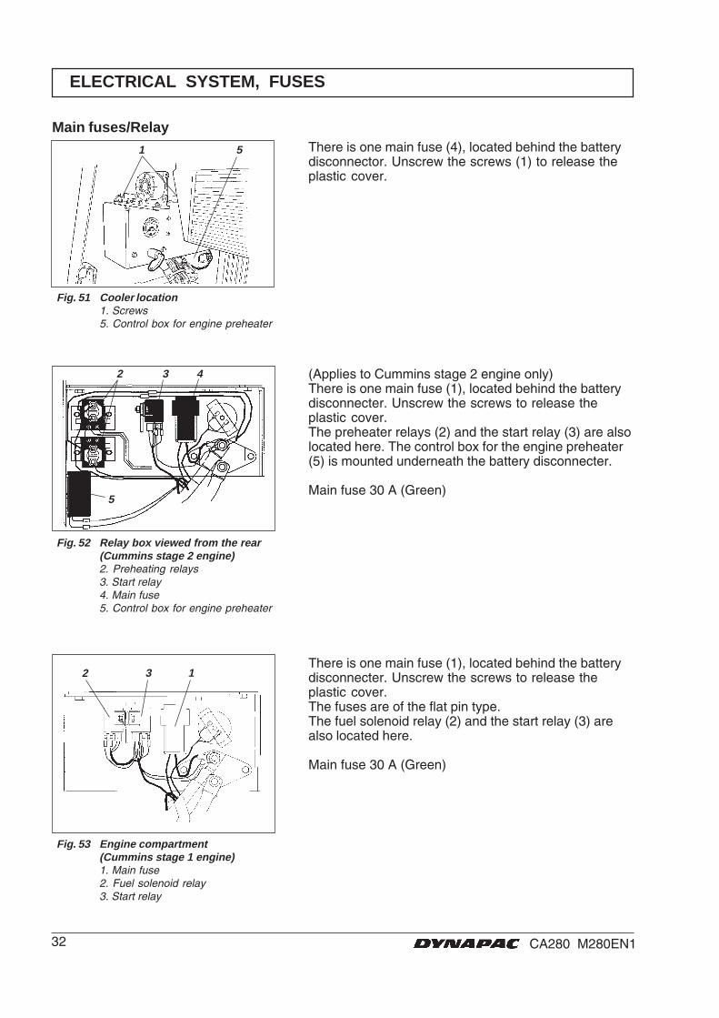
There is one main fuse (4), located behind the batterydisconnector. Unscrew the screws (1) to release theplastic cover.
ELECTRICAL SYSTEM, FUSES
Main fuses/Relay
Fig. 51 Cooler location1. Screws5. Control box for engine preheater
Fig. 53 Engine compartment(Cummins stage 1 engine)1. Main fuse2. Fuel solenoid relay3. Start relay
There is one main fuse (1), located behind the batterydisconnecter. Unscrew the screws to release theplastic cover.The fuses are of the flat pin type.The fuel solenoid relay (2) and the start relay (3) arealso located here.
Main fuse 30 A (Green)
Fig. 52 Relay box viewed from the rear(Cummins stage 2 engine)2. Preheating relays3. Start relay4. Main fuse5. Control box for engine preheater
(Applies to Cummins stage 2 engine only)There is one main fuse (1), located behind the batterydisconnecter. Unscrew the screws to release theplastic cover.The preheater relays (2) and the start relay (3) are alsolocated here. The control box for the engine preheater(5) is mounted underneath the battery disconnecter.
Main fuse 30 A (Green)