DYNAMIK DURCH WIDERSTAND DYNAMICS …€¦ · WiderstANd Wir über uns dyNAMics throuGh ... filter...
135
DYNAMIK DURCH WIDERSTAND DYNAMICS THROUGH RESISTANCE
Transcript of DYNAMIK DURCH WIDERSTAND DYNAMICS …€¦ · WiderstANd Wir über uns dyNAMics throuGh ... filter...

D Y N A M I K D U R C H W I D E R S T A N D
D Y N A M I C S T H R O U G H R E S I S T A N C E

www.fr iz len.com
d i e k L A s s i k e rdrahtgewickelte rohrfestwiderstände10 bis 6000 Watt
t h e o r i G i N A L o N e sWirewound tubular fixed resistors 10 up to 6000 Watt
d i e F L e X i b L e NZementierte drahtdrehwiderstände
16 bis 1500 Watt
t h e F L e X i b L e o N e scement coated wirewound variable resistors16 up to 1500 Watt
d i e i N N o v At i v e Ndrahtgewickelte Flachwiderstände, auch gekapselt und in wassergekühlter Ausführung
5 bis 40000 Watt
t h e i N N o v At i v e o N e sWirewound flat resistors, also enclosed and watercooled5 up to 40000 Watt
d i e b e L A s t b A r e NLast- und Prüfwiderstände
0,01 bis 250 Kilowatt
t h e L o A d A b L e o N e sLoad- and test resistors0.01 up to 250 Kilowatt
d i e M o d u L A r e Ndrahtgewickelte Lamellenfestwiderstände
0,15 bis 30 Kilowatt
t h e M o d u L A r o N e sWirewound lamina type fixed resistors0,15 up to 30 Kilowatt
d i e r o b u s t e Nstahlgitterfestwiderstände
0,5 bis 250 Kilowatt
t h e r o b u s t o N e ssteel-grid fixed resistors0,5 up to 250 Kilowatt
F r i Z L e N s o N d e r G e r Ä t edc-PoWersWitchkundenspezifische Widerstandsgeräte
F r i Z L e N s P e c i A L d e v i c e sdc-PoWersWitchcustomised resistor units
d y N A M i k d u r c h W i d e r s tA N dWir über uns
d y N A M i c s t h r o u G h r e s i s tA N c eAbout us

Anwendungen Application Typleistung [kW]Typical power
ProduktgruppeProduct group
min. max. T 100 T 200 T 300 T400 T 500 T 600Bremswiderstände für Frequenzum richter- und Gleichstrom antriebe
Braking resistors for frequency converters and DC drives
0,01 40,0 X X
0,01 6,0 X X X
6,0 30,0 X X
30,0 250 X
Belastungswiderstände für Spannungsquellen, Batterien, USV-Geräte, Generatoren und Netzgeräte
Load resistors for supply units, power packs, batteries, UPS units and generators
0,01 250 X
Stufenlose Drehzahlverstellung von kleinen Gleich- und Wechselstrommotoren
Stepless variable speed adjustment for small AC and DC motors
0,01 1,5 X X
Feldsteller für Generatoren, Widerstände zur Strom- und Spannungsbegrenzung
Field rheostats for generators, resistors for current and voltage limitation
0,01 3,8 X X
Motorische Potentiometer als fernbetätigte Sollwertgeber
Motorised potentiometers as nominal value setters
0,01 1,5 X
Widerstandsbaugruppen für Einbau in leistungselektronische Geräte
Resistor modules fitting into electronic power devices
0,01 0,75 X X X
0,3 2,0 X
Anlass- und Stellwiderstände für Schleifringläufer- und Gleichstrommotoren
Starting and regulating resistors for slip-ring rotor and DC motors
0,15 30,0 X
0,5 250 X
Ständer-Vorschalt widerstände für Kurzschlussläufermotoren
Stator series resistors for squirrel-cage motors
0,5 250 X
Strombegrenzungs widerstände zur Ladung und Entladung von Kondensatoren
Resistors for current limitation e.g. for charging and discharging of capacitors
0,01 1,0 X X X
Experimentier- und Prüfwider-stände in Laboratorien, Schulen und Universitäten
Resistors for experimenting and testing in laboratories, schools and universities
0,01 50 X
Widerstände zur Schutz-beschaltung, Filterwiderstände
Protective resistors, filter resistors
0,01 0,75 X X X
0,75 6,0 X X
1,5 22,0 X
P r o d u k t ü b e r s i c h t P r o d u c t s u r v e y
das richtige Produkt für ihre Anwendung suitable products for your application
www.fr iz len.com
Wir über uns
Mit FRIZLEN Leistungswiderständen haben Sie elektrische
Leistung voll im Griff.
Unser umfassendes Know-how zeigt sich im kompletten
Spektrum vom Einzelstück bis zur Serie, für Leistungen
von 5 Watt bis 250 Kilowatt.
Einsatz- und Anwendungs gebiete stellen die Anforder-
ungen, die Lösungen entwickeln wir.
Ihrem Anforderungsprofil entsprechend berechnen und
fertigen wir Widerstände und Widerstandskombinationen
unter Berücksichtigung Ihrer Vorgaben. Natürlich beraten
wir Sie gern und ermitteln auf Wunsch die Widerstands-
dimensionierung mit Hilfe EDV-gestützter Berechnung und
Simulation.
Hochwertige Standard- sowie Sonderlösungen von
FRIZLEN sorgen für Dynamik im Verbund mit leistungs-
elektronischen Geräten in Maschinen und Anlagen.
Bewegung zu stoppen, konstant zu halten und exakte
Abläufe zu ermöglichen – dabei unterstützen wir die
elektrische Antriebstechnik und verbessern so die
Dynamik Ihrer Antriebe.
About us
Keep your electric power under control with FRIZLEN
power resistors.
Our extensive know-how is demonstrated in a complete
spectrum from single item up to series production, for
power values from 5 watts up to 250 kilowatts.
Different ranges of use and application set the
requirements, we provide the solutions.
We design and produce resistors and resistor combina-
tions exactly to meet your requirements. We are, of
course, happy to advise you according to your specifica-
tion. Upon request, we can determine resistor dimen-
sioning using our computer-supported calculation and
simulation system.
High-quality standard and special solutions from FRIZLEN
ensure dynamics when you are dealing with high perfor-
mance electrical equipment in machines and processes.
We support electrically driven power engineering by stop-
ping movement, keeping it constant and ensuring exact
sequences, which improves the dynamics of your drive
systems.

t100
t 1 0 0 – d i e k L A s s i k e r / t h e o r i G i N A L o N e s
drahtgewickelte rohrfestwiderstände10 bis 6000 Watt
Drahtgewickelte Rohrfestwiderstände, aufgebaut als Einzelrohre, die
einbaufähig sind und daraus aufgebaute Rohrfestwiderstandsgeräte in
verschiedenen Schutz- und Befestigungsarten.
In zementierter und unzementierter Ausführung
Für Anschluss an Löt-, Schraub- oder Flachsteckanschlüssen, mit
oder ohne Abgreifschellen
Widerstandskombinationen bestehend aus einem bis sechs Rohren
Für Befestigung mit Gewindebolzen, Steckwinkeln oder Stirnblechen
in Schutzart IP00
Mit Gehäuse für waagerechte oder senkrechte Befestigung in
Schutzart IP20, Anschluss an Klemmen
Thermisches Überstromrelais, Temperaturschalter oder FRIZLEN
DC-Powerswitch für thermische Überwachung und Abschaltung
Wirewound tubular fi xed resistors10 up to 6000 Watt
Wirewound tubular fi xed resistors as individual components, that can
be integrated into other units and composed to tubular fi xed units in
different degrees of protection and mounting types.
In cemented and uncemented version
Variable connections at soldering, fast-on or screw clips, with or
without adjustable clips
Units consisting of one to six tubes
In degree of protection IP00 with threaded rods, fastening
brackets or side-panels
In degree of protection IP20 with enclosure for horizontal and
vertical mounting, connection on terminals
Thermal overload relay, temperature switch or FRIZLEN
DC-Powerswitch for thermal monitoring and switch off
www.fr iz len.com

FRIZLEN GMBH U. CO KG. TEL: 07144/8100-0 FAX: /207630 [email protected] r03 T101E Subject to alteration
Tubular fixed resistors
Contents
Properties
Applications
This list comprises wirewound tubular fixed resistors as individual components in uncemented version FU as well as in cemented version FZ as the standard version. All the components can be integrated into other units. The assembled tubular fixed resistor units are available in different degrees of protection and mounting methods. maximum characteristics type series page power general survey T102E
technical details T103-108E
1000 W suitable for integration, FZ/FU, FZB/FUB T109-110E
44 W for printed circuit board mounting FZ...L /FU...L T111E
300 W with fastening brackets, loose and/or mounted FZS /FUW T112-113E
900 W for vertical mounting F..N /F..R /F..P T114-115E
1000 W with side-panels FZ.H /FU.H T116E
3000 W with cover FZ.A. T117E
3000 W with cover and terminals FZ.M. T118E
6000 W with cover, terminals in terminal box FZ.G. / FZ.C T119-120E
6000 W with thermal overload relay FZ.T. T121E
6000 W with FRIZLEN DC-POWERSWITCH FZ.X. T122E low temperature coefficient
constant ohmic value over a large temperature range (s. p. T103E)
force locking fixation of wire using cementation
good heat conducting properties
variable resistance value adjustable by clips
change and/or adjustment or trimming by the user (s. type series description)
various diameters and lengths can be integrated, various possibilities for connection and mounting
enclosures made from hot galvanised steel sheet various protection and mounting types
low-noise and low-induction version available used for apartment buildings, hospitals, opera houses and theatres
thermal overload relay or temperature switch available integrated warning for high operating security
(serialized with series FZ..Q and F..T)
intrinsically safe
to switch off the resistor safely by FRIZLEN DC POWERSWITCH
UL-recognition for American and Canadian market (E212934) on request for type series FZ.P., FZ.M., FZ.C and FZ.T..
braking resistors for frequency converters and DC drives, in low-noise version also for
hospitals and theatres.
load resistors for supply units, power packs, batteries, UPS units and generators
resistors for current and voltage limitation e.g. for charging and discharging of capacitors
field rheostats for generators
protection and damping resistors

T102E r03 FRIZLEN GMBH U. CO KG. TEL: 07144/8100-0 FAX: /207630 [email protected] Subject to alteration
Tubular fixed resistors
symbol
T 100 - Survey
type series characteristics
page
FZ FU
FZB FUB
T109E / T110E
FZ..x.L+
FU..x.L
T111E
FZS FUS FZW FUW
T112E / T113E
F..N F..R F..P
T114E / T115E
FZ.H +
FU.H
T116E
FZ.A
T117E
FZ.M
T118E
FZ.G +
FZ.C
T119E / T120E
FZ.T
T121E
FZ.X
T122E
typical power from [W] 12 12 12 12 430 65 65 65 150 300
typical power up to[W] 1000 44 300 900 3000 3000 3000 6000 6000 6000
max. terminal / connection # (without adjustable tap and temperature switch)
2 2 2 6 2 2 2 2 2 2
degree of protection IP00 X X X X
degree of protection IP20 - if mounted on an appropriate surface
X X X X X
degree of protection IP20 terminals protected against contact X X
integration possible X X X X
horizontal mounting X X X X X
vertical mounting X X X X X
vertical mounting on mounting sheet
X
thermal overload relay X
adjustable clip available X X X X X
temperature switch (optional) X X X X X X X
FRIZLEN DC-POWERSWITCH X
X (only FZ.P)
X X (only FZ.C)
X
IP
20
IP
20
IP
00
E
with recognition
Rights for improvements and modifications of our products reserved. Modifications, errors and misprints justify no claim for damages.
We refer to our terms of sales and delivery.
FRIZLEN GMBH U. CO KG. TEL: 07144/8100-0 FAX: /207630 [email protected] r03 T103E Subject to alteration
Tubular fixed resistors
Technical details
Construction
Type series FZ..
Type series FU..
Resistance values/ Production tolerance/
Temperature dependency
Preferred ohmic values
Time constant
Adjustable clips
The basis are high quality ceramic or porcelain tubes with diameters of 16, 24, 35, 45 and 65 mm. We use round wires or bands that are made from various alloys, but mainly from CuNi 44 according to DIN 17471, 46460-1 and 46461 or NiCr 3020 and/or CrAl 25 5 according to DIN 17470. Above mentioned wires are wound with pitch and are used for cement coated fixed and adjustable resistors. (FZ..) Then they are fixed by a special cement coat. The selection of a tubular fixed resistor for continuous dissipation is only determined by the size of the surface, that means the size of tube, and by the maximum allowable temperature on the surface. We highly recommend this construction type for all standard applications as well as for short time operations with braking resistors. If a very high short time power should be dissipated on the smallest possible surface, this energy must be absorbed by the weight of the resistance material within the first second. For producing our uncemented tubular resistors we wind an oxidized wire without gap. Its oxidation functions as insulation. The wire is not protected by a cement coat. If you compare this type to the cemented one you will reach much higher wire weights on the very same surface. Therefore this version is constructed for a very high, not pulsating amount of energy during a short time, like during charging or discharging of capacitors. You will pick this version when you are dealing with single switching operations. For slide resistors, please look at our technical list T400E. The resistance values in the column “production range“ refer to our standard production range and appear in row E12*. Please select from there. Different values upon request. The normal tolerance is 10%. Smaller tolerances upon request. The resistance value will change slightly in dependency of the winding temperature. With T 300 K the resistance will change compared to a cooled down condition as follows: with wires made of CuNi 44 approx. ±1%, made of CrAl 25 5 approx. +1% and made of NiCr 3020 approx. +10%. We select the alloys corresponding to the resistance values or to demand. You will find indications concerning temperatures on page T105E and T106E. *E12: multiplication or division by integer potencies of 10 with the following values:
1,0 - 1,2 - 1,5 - 1,8 - 2,2 - 2,7 - 3,3 - 3,9 - 4,7 - 5,6 - 6,8 - 8,2 The average thermal time constant is 300 s. Tubular fixed resistors of different type series can be flexibly equipped with adjustable clips to adapt the resistance values (compare e.g. page T109E, T111E-114E, T116E and T117E). The clips may only be adjusted in a condition free of voltage and after sufficient loosening and cooling. All our adjustable clips are equipped with silver contacts. When selecting please consider that the maximum temperature on the surface should not exceed 300°C. Please mind the details on pages T106E and T107E, too.

T104E r03 FRIZLEN GMBH U. CO KG. TEL: 07144/8100-0 FAX: /207630 [email protected] Subject to alteration
Tubular fixed resistors
Degrees of protection
Air and creepage distances
Protective measures
UL-Recognition
Excess current protection
Correlation of type series and degrees of protection according to EN 60529 and/or DIN VDE 0470 part 1 Type series
Degree of protection
First digit degree of protection against access & solid foreign objects
Second digit degree of protection against water
FZ., FU. F.S., F.W., F.H.
IP 00 Non-protected – i.e. depending upon integration the user must provide a protection
Non-protected
F..A, F..C,F..G, F..M,F..T. F..X
IP 20 Non-protected
F..N, F..R, F..P
IP 20
Protected against access to hazardous parts with a finger and against solid foreign objects of 12,5mm and greater.
Non-protected
if mounted on an appropriate surface – i.e. mounted on a surface according to degree of protection IP 20 or higher Terminals are protected against access to hazardous parts according to BGV A2 Air and creepage distances are rated according to IEC 664 (DIN EN 0110 part 1) for the overvoltage category III and degree of pollution 3 for grounded three-phase mains supplies up to 3 x 500 V. Testing voltage 2.5 kV AC. These data are valid for all devices that are connected to mains voltage and derived voltages, as for example the intermediate circuit voltage of frequency converters. Do not conclude from the calculated relation between the rated power and the maximum producible ohmic value to the rated voltage!
All our power resistors with degree of protection IP 20 and IP 20, correspond to safety class I, i.e. connections for protective earth conductor according to EN 61140 are provided. These devices also comply with the CE low voltage directive. Power resistors being passive electronical or electrical units are not affected by the specific EMC standards. They do not produce any interfering radiations nor are they affected. Some important type series can be delivered in a version with UL-recognition both for the American and for the Canadian market. The devices are UL 508 approved, number E212934. This recognition is the same as a recognition according to CSA C22.2 No.14. For further information please check the UL-flyer. (Please ask for it or visit us at www.frizlen.com) A protection of the resistors against overloading or excess temperature - as demanded in standards - can be realized with the help of a thermal overload relay provided by the user. The set current must correspond to the rated current of the resistor, that is calculated according to continuous duty power and resistance value corresponding to Ohm's law (formula: see "terminal details" p. T108E) Concerning the series FZ..T the thermal overload relay is a component of the device - with exceeding of the rated current a signal contact is released. There will not be a disconnection of the resistor. Resetting by hand.
IP
00 IP
20
IP
20

FRIZLEN GMBH U. CO KG. TEL: 07144/8100-0 FAX: /207630 [email protected] r03 T105E Subject to alteration
Tubular fixed resistors
Excess temperature protection
Intrinsically safe version with FRIZLEN
DC-POWERSWITCH
Contact rating
Storage temperature/ Operation temperature/
Installation altitude
Typical power/ Continuous dissipation/
Ventilation/ Temperatures
Another kind of the excess temperature monitoring, particularly suited for long-term overloading, is the equipment with a temperature switch. In IP 20-resistor devices it is wired on terminals, in IP 00 resistors the switch is directly connectable and releases a signal contact, when the set temperature is exceeded. There will not be a disconnection of the resistor. You can inform yourselfs about function and restrictions by our data sheet „Tripping of monitoring devices“. We can send it to you on request. Integrated overload switch for a maximum of 850 VDC to protect the resistor. It protects the integrated resistor against constant overload and against too high short time peak power, e.g. caused by a false operational mode or a fault by an short circuited chopper transistor. Possible damage in the environment by overheating and burning are effectively avoided.
So you receive an intrinsically safe resistor protection degree even for IP20. The FRIZLEN DC-POWERSWITCH can also be integrated in the switch cabinet. After a successful fault clearance the DC-POWERSWITCH can be switched on like a normal automatic cutout. We can send you more technical details and characteristics on request.
Attention: FRIZLEN DC-POWERSWITCH are only suited for monitoring and disconnecting from DC-voltage with pure resistive load (DC1) up to 850 VDC. Contact ratings of the signal contacts of temperature switches and thermal overload relays. 2 A / 24 VDC (DC11) 2 A / 230 VAC (AC11) Contact ratings of the signal contacts of the DC-POWERSWITCH: 5 A / 24 VDC (DC11) 10 A / 230 VAC (AC11) Storage temperature: - 40° C to 80° C Operation temperature: - 30° C to 40° C. If the ambient temperature is higher than
40°C, you have to decrease the continuous dissipation by 4% per 10 K temperature rise!
Installation altitude: 2000 m above sea level, you have to decrease the continuous dissipation for 10% per 1000 m altitude, maximum altitude 5000 m above sea level
Restrictions are to be made for the type series FZ.T. and FZ.X. because of the built-in monitoring device. Operation temperature: - 20° C to 40° C The given typical power values are valid for 100% duty cycle factor (DCF) (continuous dissipation) under the following conditions: temperature rise of 200 K at the surface of fixed resistor enclosures (degree of
protection> IP00) temperature rise of 300 K at the surface of fixed resistor elements (degree of
protection IP00) unhindered access of cooling air unhindered diverting of warmed up air (mind a minimum separation distance of
approx. 200 mm to neighbouring components/walls and of approx. 300 mm to components above/ceiling)
RES
RB1 RB2 T2 T1

T106E r03 FRIZLEN GMBH U. CO KG. TEL: 07144/8100-0 FAX: /207630 [email protected] Subject to alteration
Tubular fixed resistors
Ventilation/ Temperatures
Since electrical energy is converted into heat, heating up of the exhaust air and of the enclosure at the air outlet is inevitable. The highest temperature at typical power may be maximum 200°C above the ambient temperature. Since the cooling of the devices is accomplished by convection, the above mentioned aspects have absolutely to be considered. In cases of insufficient cooling or false mounting the resistor or the surrounding devices could be overheated or ruined. Depending upon use it can be possible to increase the continuous dissipation of the resistors, if higher temperatures are accepted. With an increase of e.g. 130% of the typical power you will have a rise in temperature of 350K at the surface of the resistor. In other cases of application the continuous dissipation must be reduced, for example with temperature sensitive devices in the surrounding area. The dependence between temperature rise and actual continuous dissipation is shown in the diagram below.
Normal operation range (up to 130%):
Recommended operation range for maximum product life and failure free operation Allowable threshold (up to 160%):
Allowable operation range, danger of shorter product life and higher failure probability Unallowable operation range (more than 160%):
Danger of excessive heat and destruction of resistor and neighbouring components
0
100
200
300
400
500
0 50 100 150 200 250
Continuous dissipation in % of typical power
Exc
ess
tem
per
atu
re [
K]
Excess temperature in dependence of continuous dissipation
At the resistor element
normal operation range
allowable threshold unallowable operation range
At the enclosure surface

FRIZLEN GMBH U. CO KG. TEL: 07144/8100-0 FAX: /207630 [email protected] r03 T107E Subject to alteration
Tubular fixed resistors
Short time dissipation/ Total cycle time/
Duty cycle factor(DCF)
Overload factor(OLF)
Calculation example given:
wanted: continuous dissipation
At many applications resistors are not loaded in continuous but in short time operation. In the following you will find indications, how to calculate the allowable short time dissipation with the help of the duty cycle factor (DCF) and the overload factor (OLF). If the DCF factor is not known, it can be calculated as follows:
Warning: The total cycle time may be maximum 120 s - shorter total cycle times are possible. The total cycle times for motors are mostly higher than 120 s
By comparison of the known DCF-factor with the following diagram or table you can work out the overload factor (OLF) and/or the continuous and the short time dissipation.
DCF 1% 3 % 6% 15% 25% 40% 60% 80% 100% OLF 30 15 9,5 5,0 3,2 2,2 1,5 1,12 1,0
The continuous and the short time dissipation can be calculated as follows:
Resistor with a short time dissipation of 2,5 kW for 18 s and a total cycle time of 120s
The duty cycle factor (DCF) is 18 s : 120 s x 100% = 15% Overload factor (OLF) for 15% DCF, according to table it is 5,0 The continuous dissipation is 2,5 kW : 5,0 = 0,5 kW;
You need a resistor with a continuous dissipation of at least 0,5 kW!
Total cycle time = 120 s
ton = 48 s
Total cycle time = 30 s
ton = 7,5 s
%404,0120
481
s
sDCF
timecycleTotal
ttimeonSwitchDCFfactorcycleDuty on)(
%2525,030
5,72
s
sDCF
OLFndissipatioContinuousndissipatiotimeShort
OLFfactorOverload
ndissipatiotimeShortndissipatioContinuous
Overload factor (OLF) in dependence of duty cycle factor (DCF)(Total cycle time = 120s)
DCF
OLF
- o
f tu
bula
r fix
ed
re
sist
ors
1% 6% 10% 25% 40% 60% 100%
30
10
3
1

T108E r03 FRIZLEN GMBH U. CO KG. TEL: 07144/8100-0 FAX: /207630 [email protected] Subject to alteration
Tubular fixed resistors
Terminal details/ Monitoring devices/
Cross section
Wiring
Low-noise and low-inductive version
Mounting
Rated current and cross section of terminals and monitoring types. Type abbreviation rated
current in A with 100%
DCF
rated current in A up to 40%
DCF
Maximum cross section
porcelain terminal
PK 20 25 up to 2,5 mm²
ceramic flat terminal
FK 35 44 2,5 - 10 mm²
G 5 30 38 0,5 – 2,5 (4) mm²
AWG 24 - 12 device terminal out of polyamide (PA) G 10 60 75
0,5 – 10 (16) mm² AWG 20 - 6
ST2,5 20 25 up to 2,5 mm² AWG 16 - 12
cage clamp terminal out of PA ST 4 30 38
up to 4,0 mm² AWG 20 - 10
signal contact 2 - up to 2,5 mm²; AWG 16-12
thermal overload relay main
connection up to 17/24 21/30 2,5/6 mm²;
AWG 20 - 10
signal contact 10 - up to 2,5 mm² AWG 16 - 12 DC-POWER-
SWITCH FPS main connection 40 50
up to 16 mm²; AWG 4
The rated current is calculated in each case due to Ohm`s law as follows:
whereas P is the power of the resistor and R is the value of the resistance
If terminals are delivered by us, the connections are wired with flexible, heat resistant, silicone-insulated wire on terminals (further wires on request). If the wiring is accomplished by the customer, make sure that a heat resistant wire is used. By means of a bifilar winding we are able to provide a low-noise and low-inductive version for operations in noise sensible areas, such as braking resistors for frequency converters for lift motors in hospitals or apartment houses. The same is valid for hoist motors on theatre stages. Please mind the mounting indications of the corresponding type series! You will find these icons in the data sheets. Allowable: On horizontal surfaces Allowable: On vertical surfaces, terminals at the bottom
Allowable: Mounting vertical to the mounting sheet, terminals at the bottom
Not allowable: On vertical surfaces, terminals at the top, left or right
Not allowable: On horizontal surfaces, terminals at the top
R
PI
FRIZLEN GMBH U. CO KG. TEL: 07144/8100-0 FAX: /207630 [email protected] r03 T109E Subject to alteration
Tubular fixed resistors
Type series FZ / FU Type series FZB / FUB Technologies connection directly at the resistor optional, depending on construction
size with screw, fast-on or soldering connection
adjustable clips (Ags.) available (please mind the hints on this page and on the following one)
with type series F.B.. only small mounting space is needed
mounting in switch cabinets We provide M3 screw connections for construction sizes with diameters D=16 and M4 with D=24/35/45 M5 with D=65. Also fast-on connections (6,3x0,8) are available for sizes with D=24/35/45. For sizes with D=16 the soldering connections can also be used as fast-on connections (4,8x0,5). You will find the electrical and mechanical data on the next page. You will find indications for the relationship between load capacity and temperature on the surface as well as for the dimensioning of the resistor at short term load in chapter “Technical Details”, pages T103E-T108E. Application As ballast, limiting, filter or series resistors etc. for integration into devices and customised units. Our type series F.B.. is very well applicable in switch cabinets. We fix the threaded rod for you in a space-saving way. Efficient use in your manufacturing systems.
Special design various tube sizes as well as lower
and higher ohmic values on request beginning with size D=24 also with
temperature switch (TS) with fast-on connections 6,3 x 0,8
soldering connections, pretinned
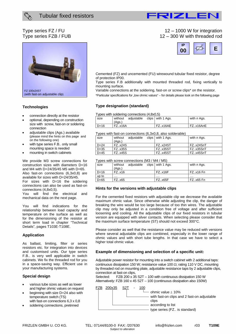
12 – 1000 W for integration 12 – 300 W with threaded rod
Cemented (FZ) and uncemented (FU) wirewound tubular fixed resistor, degree of protection IP00. Type series F.B additionally with mounted threaded rod, fixing vertically to mounting surface. Variable connections at the soldering, fast-on or screw clips* on the resistor. *Particular specifications for „low ohmic values“ – for details please look on the following page
Type designation (standard) Types with soldering connections (4,8x0,5) size without adjustable clips
(Ags.) with 1 Ags. with n Ags.
D=16 FZ..x16A FZ..x16AE FZ..x16AnE Types with fast-on connections (6,3x0,8, also solderable) size without adjustable clips
(Ags.) with 1 Ags. with n Ags.
D=24 FZ..x24S FZ..x24ST FZ..x24SnT D=35 FZ..x35S FZ..x35ST FZ..x35SnT D=45 FZ..x45S FZ..x45ST FZ..x45SnT
Types with screw connections (M3 / M4 / M5) size without adjustable clips
(Ags.) with 1 Ags. with n Ags.
D=16 FZ..x16 FZ..x16F FZ..x16 Fn up to .... .... .... D=65 FZ..x65 FZ..x65F FZ..x65 Fn
Hints for the versions with adjustable clips For the cemented fixed resistors with adjustable clip we decrease the available maximum ohmic value. Since otherwise while adjusting the clip, the danger of breaking the wire would be too large because of too thin wires. The adjustable clip may only be adjusted in a condition free of voltage and after sufficient loosening and cooling. All the adjustable clips of our fixed resistors in tubular version are equipped with silver contacts. When selecting please consider that the maximum surface temperature (ST) should not exceed 300°C. Please consider as well that the resistance value may be reduced with versions where several adjustable clips are combined, especially in the lower range of ohmic values and with short tube lengths. In that case we have to select a higher total ohmic value.
Example of dimensioning and selection of a specific unit:
Adjustable power resistor for mounting into a switch cabinet with 2 additional taps: continuous dissipation 150 W; resistance value 100 ; rating 110 V DC, mounting by threaded rod on mounting plate, adjustable resistance taps by 2 adjustable clips, connection at fast-on clips, Selected: FZB 200 x 35 S2T – 100 with continuous dissipation 150 W Alternatively: FZB 160 x 45 S2T – 100 (continuous dissipation also 150W)
FZB 200x35 S2T - 100 ohmic value 10% with fast-on clips and 2 fast-on adjustable
clips according to list type series (FZ.. is standard)
IP
00
FZ 100x24ST (with fast-on adjustable clip)
E

T110E r03 FRIZLEN GMBH U. CO KG. TEL: 07144/8100-0 FAX: /207630 [email protected] Subject to alteration
Tubular fixed resistors
Type series FZ / FU Type series FZB / FUB
12 - 1000 W for integration 12 – 300 W with threaded rod
Electrical and mechanical data
production range Wert dimension in mm
for screw clips
for soldering
and fast-on clips
with adjust-
able clip
without adjust-
able clip
with adjust-
able clip(s)
only for types with screw
clips
only type series FZB./
FUB.
type series
FZ.. (standard)
/ FU.. L x D
typical power in
W at 40°C,
100%DCF and 300°C
ST from up to B E F* G T
approx. weight in
g
F. 50x16.. 12 0,27 0,27 0,68 6,8k 1,8k 20 34 33 33 72 40F. 63x16.. 18 0,39 0,39 1,0 10k 2,7k 20 45 33 33 87 50 F. 100x16.. 34 0,68 0,68 1,8 18k 4,7k 20 82 33
M3 33 122 60
F. 75x24.. 32 0,1 0,33 1,8 18k 3,9k 28 55 34 44 97 100 F. 100x24.. 44 0,15 0,47 2,2 27k 5,6k 28 78 34 44 122 120 F. 165x24.. 80 0,33 1,0 3,9 39k 10k 28 137 34 44 190 190 F. 265x24.. 140 0,56 1,8 8,2 68k 15k 28 237 34
M4
44 290 300 F. 100x35.. 65 0,22 0,68 1,0 22k 8,2k 38 78 44 53 122 160 F. 135x35.. 100 0,33 1,0 2,2 33k 12k 38 113 44 53 155 210 F. 200x35.. 150 0,56 1,8 8,2 47k 15k 38 172 44 53 220 290 F. 330x35.. 250 1,0 2,7 12 82k 27k 38 282 44
M4
53 350 460 F. 160x45.. 150 0,47 6,8 6,8 33k 10k 48 125 54 63 178 340 F. 200x45.. 180 0,68 10 10 39k 12k 48 164 54 63 220 450 F. 300x45.. 300 1,2 15 15 56k 18k 48 250 54
M4/M5**
63 320 560 F. 300x65.. 430 6,8 20 47k 18k 68 250 80 90 1100 F. 400x65.. 600 10 30 68k 22k 68 350 80 90 1400 F. 500x65.. 800 12 39 82k 33k 68 450 80 90 1800 F. 600x65.. 1000 15
special design
47 100k 39k 68 550 80
M5
90
special design
2100
*when equipped with an additional adjustable clip, maximum dimension for the version with screw connection is dimension G instead of dimension F! (Comparable to types with fast-on connection) ** for smaller resistor values M5, more details on request
FZ / FU 50x16.. up to FZ / FU 100x16.. (not shown) and FZB / FUB 50x16.. up to FZB / FUB 100x16.. (shown)
E
with fast-on clips with screw clips with screw clip and adjustable clip(s)
FZ / FU 75x24.. up to FZ / FU 300x45.. (not shown) and FZB / FUB 75x24.. up to FZB / FUB 300x45.. (shown)
E
with fast-on clips with screw clips with screw clip and adjustable clip(s)
FZ / FU 300x65 up to FZ / FU 600x65 (shown)
EM5
5,5
M5
with screw clips with additional adjustable clip(s) For detailed information, e.g. referring to special tube cross sections, ask for our dimension sheets 11M0318, 11M0319, 11M0320, 11M0321, 11M0322 or 11M0323, or just dial the phone number below.
(M5**)

FRIZLEN GMBH U. CO KG. TEL: 07144/8100-0 FAX: /207630 [email protected] r03 T111E Subject to alteration
Tubular fixed resistors
Type series FZ...L / FU...L Technologies connection and mounting directly by
means of the resistor soldering clips mounting directly on PCB The given power values can be essentially increased during short time operation as a function of the duty cycle factor (DCF) The peak power can be easily calculated. Just multiply the values by the corresponding overload factors (OLF) of this table:
DCF 60% 40% 25% 15% 6%
OLF 1,5 2,2 3,2 5,0 9,5 These overload factors OLF are valid for a total cycle time of maximum 120 s You will find further indications in chapter “Technical Details”, pages T103E-T108E. Application As ballast, limiting, filter or series resistors on printed circuit boards. Reliable and efficient manufacturing process by optionally pretinned soldering connections. Special design Special sizes on request
12 – 44 W with soldering clips, for mounting on a printed circuit board
Cemented wirewound tubular fixed resistor, degree of protection IP00, for soldering on printed circuit boards, mounting and connection by soldering clips horizontal to mounting surface. Connections pretinned. Electrical and mechanical data
production range value
dimensions in mm approx. weight in g
Type series FZ..L (standard) /FU..L L x D
typical power in W
at 40°C, 100%DCF and 300°C
ST
from up to L E
F. 50x16L 12 0,27 6,8k 50 34 45F. 63x16L 18 0,39 10k 63 45 55 F. 100x16L 34 0,68 18k 100 82 65 F. 75x24L 32 0,33 18k 75 55 120 F. 100x24L 44 0,47 27k 100 78 320
Example of dimensioning and selection of a specific unit:
resistor for mounting on a printed circuit board : continuous dissipation 30 W; resistance value 1 k; selected: FZ 75x24 L – 1k with continuous dissipation 32 W
FZ 75x24 L - 1k ohmic value 10% with soldering connections according to list type series(FZ.. is standard)
FZ/FU 50x16L up to FZ/FU 100x16L
E
FZ/FU 75x24L up to FZ/FU 100x24L
E
11 M 0161
IP
00
FZ 100x24 L
E

T112E r03 FRIZLEN GMBH U. CO KG. TEL: 07144/8100-0 FAX: /207630 [email protected] Subject to alteration
Tubular fixed resistors
Type series FZS / FUS Technologies connections directly at the resistor optional with either screw, fast-on or
soldering connections integration into switch cabinets adjustable clips available insertable fastening brackets are
enclosed loose. The given power values are valid for 100%DCF (continuous dissipation) at an ambient temperature of max. 40°C and a surface temperature (ST) of 300°C. The values can be increased by the factor 1,3. Then the ST will increase up to approx. 350°C. The given power values can be essentially increased during short time operation as a function of the duty cycle factor (DCF) The peak power can be easily calculated. Just multiply the values by the corresponding overload factors (OLF) of this table:
DCF 60% 40% 25% 15% 6%
OLF 1,5 2,2 3,2 5,0 9,5 These overload factors are valid for a total cycle time of maximum 120 s. Application As ballast, limiting, filter or series resistors etc in switch cabinets or electric devices. Low price and efficient operation by the easy and quick application of insertable fastening brackets in manufacturing. Special design from construction size D=24 on with
temperature switch (TS) with fast-on connections 6,3 x 0,8
12 – 250 W with fastening brackets Cemented wirewound tubular fixed resistor, degree of protection IP00, with insertable fastening brackets which are enclosed loose, fixing parallel to mounting surface. Connections by screw, fast-on or soldering clips of the resistor*. *For available connection types and designations please see pages T109E/110E Electrical and mechanical data
production range Wert
dimensions in mm approx. weight in g
Type series FZS.. (standard) FUS.. L x D
typical power in W at 40°C, 100% DCF and
300°C ST
from up to B E H J M O R P
F.S 50x16 12 0,27 6,8k 18 34 42 42 70 83 10 3,0 35F.S 63x16 18 0,39 10k 18 45 42 42 84 97 10 3,0 40 F.S 100x16 34 0,68 18k 18 82 42 42 120 133 10 3,0 50 F.S 75x24 32 0,1 18k 25 55 47 56 95 108 16 4,1 85 F.S 100x24 44 0,15 27k 25 78 47 56 120 133 16 4,1 110 F.S 165x24 80 0,33 39k 25 137 47 56 185 198 16 4,1 170 F.S 265x24 140 0,56 68k 25 237 47 56 285 298 16 4,1 260 F.S 100x35 65 0,22 22k 38 78 54 63 125 146 25 4,1 160 F.S 135x35 100 0,33 33k 38 113 54 63 160 181 25 4,1 200 F.S 200x35 150 0,56 47k 38 172 54 63 225 246 25 4,1 280 F.S 330x35 250 1,0 82k 38 282 54 63 355 376 25 4,1 440
For further details concerning the ohmic values please see pages T109E/110E.
Example: Continuous dissipation 140 W, resistance value 390 with 1 adjustable clip, with screw connections Ordering designation: FZS 265x24 F – 390
IP
00
FUS 100x35 (fastening brackets enclosed loose)
E
FZS/FUS 50x16.. up to FZS/FUS 100x16.. E
with fast-on clips with screw clips with screw clips and
one adjustable clip
FZS/FUS 75x24.. up to FZS/FUS 330x35..
E
with fast-on clips with screw clips with screw clips and one adjustable clip 11 M 0326 / 11 M 0327

FRIZLEN GMBH U. CO KG. TEL: 07144/8100-0 FAX: /207630 [email protected] r03 T113E Subject to alteration
Tubular fixed resistors
Type series FZW / FUW Technologies connections directly at the resistor optional with either screw, fast-on or
soldering connection integration into switch cabinets adjustable clips available with screwed fastening brackets The given power values are valid for 100%DCF (continuous dissipation) at an ambient temperature of max. 40°C and a surface temperature (ST) of 300°C. The values can be increased by the factor 1,3. Then the ST will increase up to approx. 350°C. The given power values can be essentially increased during short time operation as a function of the duty cycle factor (DCF) The peak power can be easily calculated. Just multiply the values by the corresponding overload factors (OLF) of this table:
DCF 60% 40% 25% 15% 6%
OLF 1,5 2,2 3,2 5,0 9,5 These overload factors are valid for a total cycle time of maximum 120 s.
Application As ballast, limiting, filter or series resistors etc in switch cabinets or electric devices. Efficient operation by the prefixed screwed fastening brackets in a range of industries.
Special design from construction size D=24 on with
temperature switch (TS) with fast-on connections 6,3 x 0,8
How to order: Example: Continuous dissipation 250 W, resistance value 5,6 Is to be wired at fast-on connections (without adjustable clip) Type designation then: FZW 330x35 S – 5,6
12 – 300 W with screwed fastening brackets Cemented wirewound tubular fixed resistor, degree of protection IP00, with screwed fastening brackets, fixing parallel to mounting surface. Connections at screw, fast-on or soldering clips of the resistor*. *For available connection types and designations please see pages T109E/110E Electrical and mechanical data
production range Wert
dimensions in mm approx.weight in g
Type series FZW.. (standard) FUW.. L x D
typical power in W at 40°C, 100% DCF and
300°C ST
from up to B E H J M O P R
F.W 50x16 12 0,27 6,8k 18 34 42 42 70 83 3,0 10 45F.W 63x16 18 0,39 10k 18 45 42 42 84 97 3,0 10 55 F.W 100x16 34 0,68 18k 18 82 42 42 120 133 3,0 10 65 F.W 75x24 32 0,1 18k 28 55 47 56 95 115 4,1 20 120 F.W 100x24 44 0,15 27k 28 78 47 56 120 140 4,1 20 150 F.W 165x24 80 0,33 39k 28 137 47 56 185 205 4,1 20 210 F.W 265x24 140 0,56 68k 28 237 47 56 285 305 4,1 20 320 F.W 100x35 65 0,22 22k 38 78 52 63 120 140 4,1 20 180 F.W 135x35 100 0,33 33k 38 113 52 63 155 175 4,1 20 220 F.W 200x35 150 0,56 47k 38 172 52 63 220 240 4,1 20 310 F.W 330x35 250 1,0 82k 38 282 52 63 350 370 4,1 20 480 F.W 160x45 150 0,47 33k 48 125 69 78 184 200 4,1 40 380 F.W 200x45 180 0,68 39k 48 164 69 78 224 240 4,1 40 430 F.W 300x45 300 1,2 56k 48 250 69 78 324 340 4,1 40 600
For further details concerning the ohmic values please see pages T109E/110E.
FZW/FUW 50x16.. up to FZW/FUW 100x16..
E
4,2x8
4,2x8
with fast-on clips with screw clips with screw clips and one adjustable clip
FZW/FUW 75x24.. up to FZW/FUW 300x45..
E
4,2x8
4,2x8
with fast-on clips with screw clips with screw clips and one adjustable clip 11 M 0324 / 11 M 0325
IP
00
FZW 160x45
E
T114E r03 FRIZLEN GMBH U. CO KG. TEL: 07144/8100-0 FAX: /207630 [email protected] Subject to alteration
Tubular fixed resistors
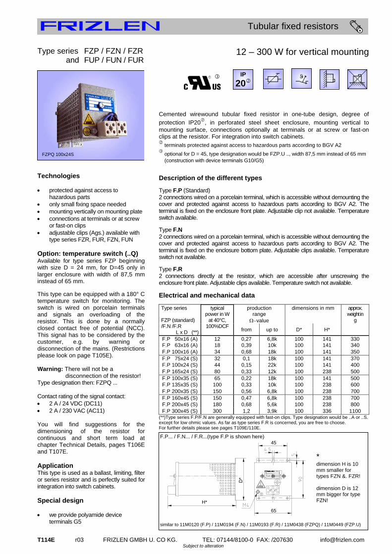
Type series FZP / FZN / FZR and FUP / FUN / FUR
Technologies protected against access to
hazardous parts only small fixing space needed mounting vertically on mounting plate connections at terminals or at screw
or fast-on clips adjustable clips (Ags.) available with
type series FZR, FUR, FZN, FUN Option: temperature switch (..Q) Available for type series FZP beginning with size D = 24 mm, for D=45 only in larger enclosure with width of 87,5 mm instead of 65 mm. This type can be equipped with a 180° C temperature switch for monitoring. The switch is wired on porcelain terminals and signals an overloading of the resistor. This is done by a normally closed contact free of potential (NCC). This signal has to be considered by the customer, e.g. by warning or disconnection of the mains. (Restrictions please look on page T105E). Warning: There will not be a disconnection of the resistor! Type designation then: FZPQ ... Contact rating of the signal contact: 2 A / 24 VDC (DC11) 2 A / 230 VAC (AC11) You will find suggestions for the dimensioning of the resistor for continuous and short term load at chapter Technical Details, pages T106E and T107E. Application This type is used as a ballast, limiting, filter or series resistor and is perfectly suited for integration into switch cabinets. Special design we provide polyamide device
terminals G5
12 – 300 W for vertical mounting
Cemented wirewound tubular fixed resistor in one-tube design, degree of
protection IP20, in perforated steel sheet enclosure, mounting vertical to mounting surface, connections optionally at terminals or at screw or fast-on clips at the resistor. For integration into switch cabinets.
terminals protected against access to hazardous parts according to BGV A2
optional for D = 45, type designation would be FZP.U .., width 87,5 mm instead of 65 mm (construction with device terminals G10/G5)
Description of the different types
Type F.P (Standard) 2 connections wired on a porcelain terminal, which is accessible without demounting the cover and protected against access to hazardous parts according to BGV A2. The terminal is fixed on the enclosure front plate. Adjustable clip not available. Temperature switch available.
Type F.N 2 connections wired on a porcelain terminal, which is accessible without demounting the cover and protected against access to hazardous parts according to BGV A2. The terminal is fixed on the enclosure bottom plate. Adjustable clips available. Temperature switch not available.
Type F.R 2 connections directly at the resistor, which are accessible after unscrewing the enclosure front plate. Adjustable clips available. Temperature switch not available.
Electrical and mechanical data
production range
value
dimensions in mm approx. weight in
g
Type series FZP (standard) /F.N /F.R L x D (**)
typical power in W
at 40°C, 100%DCF
from up to D* H*
F.P 50x16 (A) 12 0,27 6,8k 100 141 330F.P 63x16 (A) 18 0,39 10k 100 141 340 F.P 100x16 (A) 34 0,68 18k 100 141 350 F.P 75x24 (S) 32 0,1 18k 100 141 370 F.P 100x24 (S) 44 0,15 22k 100 141 400 F.P 165x24 (S) 80 0,33 12k 100 238 500 F.P 100x35 (S) 65 0,22 18k 100 141 500 F.P 135x35 (S) 100 0,33 10k 100 238 600 F.P 200x35 (S) 150 0,56 6,8k 100 238 700 F.P 160x45 (S) 150 0,47 6,8k 100 238 700 F.P 200x45 (S) 180 0,68 5,6k 100 238 800 F.P 300x45 (S) 300 1,2 3,9k 100 336 1100
(**)Type series F.P/F.N are generally equipped with fast-on clips. Type designation would be ..A or ..S. except for low ohmic values. As far as type series F.R is concerned, you are free to choose. For further details please see pages T109E/110E.
6
IP
20
FZPQ 100x24S
F.P... / F.N... / F.R...(type F.P is shown here)
D*
45
65
H*
similar to 11M0120 (F.P) / 11M0194 (F.N) / 11M0193 (F.R) / 11M0438 (FZPQ) / 11M0449 (FZP.U)
* dimension H is 10 mm smaller for types FZN &. FZR! dimension D is 12 mm bigger for type FZN!

FRIZLEN GMBH U. CO KG. TEL: 07144/8100-0 FAX: /207630 [email protected] r03 T115E Subject to alteration
Tubular fixed resistors
Type series FZZP / FZDP and FUZP / FUDP Technologies protected against access to
hazardous parts only small fixing space needed vertical mounting on mounting plate two - or three-phase version, also
available with star point in the unit, i.e. connections at 2, 3, 4 or 6 terminals
Option: temperature switch (..Q) - beginning with size D = 24 mm only! This type can be equipped with a 180° C temperature switch for temperature monitoring. It is wired on porcelain terminals and monitors an overloading of the resistor by a normally closed contact free of potential (NCC). This signal has to be considered by the customer e.g. by a warning or disconnection of the mains. (Restrictions please look on page T105E). Warning: There will not be a disconnection of the resistor! Type designation then: FZ.PQ ... Contact rating of the signal contact: 2 A / 24 VDC (DC11) 2 A / 230 VAC (AC11) You will find suggestions for the dimensioning of the resistor for continuous and short term load at chapter Technical Details, pages T106E and T107E. Application This type is used for limiting the switch-on current and for short – circuit braking in a three-phase version. Also as filter, braking or series resistor in a one- or two-phase version. It is perfectly suited for integration into switch cabinets. Special design
with polyamide device terminals G5 (max. 6 term. without TS or 3 term. with TS)
24 – 900 W for vertical mounting
Cemented wirewound tubular fixed resistor in two-tubes (F.ZP) or three-tubes
design (F.DP), degree of protection IP20, in perforated steel sheet enclosure, mounting vertical to mounting surface. For integration into switch cabinets. Standard version: One-phase resistor with 2 connections at terminals on the enclosure front plate.
terminals protected against access to hazardous parts according to BGV A2
optional for D = 45, type designation would be FZ.P.U.. (version with device terminals G10/G5)
Electrical and mechanical data
production range
value
dimensions in mm approx.weight
in kg
Type series FZ.P (standard) /F..N /F..R L x D (*)
typical power in
W at 40°C, 100% DCF from up to A B C H
F.ZP 50x16 (A) 24 0,47 12k 22,5 87,5 67,5 123 0,42F.ZP 63x16 (A) 36 0,68 18k 22,5 87,5 67,5 123 0,43 F.ZP 100x16 (A) 68 1,2 15k 22,5 87,5 67,5 123 0,45 F.ZP. 75x24 (S) 64 0,18 18k 45 110 90 123 0,62 F.ZP. 100x24 (S) 88 0,27 8,2k 45 110 90 123 0,70 F.ZP. 165x24 (S) 160 0,56 6,8k 45 110 90 190 0,85 F.ZP. 100x35 (S) 130 0,39 8,2k 75 140 120 220 1,20 F.ZP. 135x35 (S) 200 0,56 5,6k 75 140 120 220 1,30 F.ZP. 200x35 (S) 300 1,0 3,9k 75 140 120 220 1,40 F.ZP. 160x45 (S) 300 0,82 3,9k 105 178 150 220 1,40 F.ZP. 200x45 (S) 360 1,2 2,7k 105 178 150 220 1,50 F.ZP. 300x45 (S) 600 2,2 1,8k 105 178 150 318 2,00 F.DP 50x16 (A) 36 0,82 27k 22,5 87,5 67,5 123 0,45F.DP 63x16 (A) 54 1,0 18k 22,5 87,5 67,5 123 0,47 F.DP 100x16 (A) 102 1,8 10k 22,5 87,5 67,5 123 0,50 F.DP. 75x24 (S) 96 0,27 12k 45 110 90 123 0,70 F.DP. 100x24 (S) 132 0,47 8,2k 45 110 90 123 0,80 F.DP. 165x24 (S) 240 1,0 4,7k 45 110 90 190 1,10 F.DP. 100x35 (S) 195 0,68 5,6k 75 140 120 220 1,30 F.DP. 135x35 (S) 300 1,0 3,9k 75 140 120 220 1,40 F.DP. 200x35 (S) 450 1,5 2,7k 75 140 120 220 1,60 F.DP. 160x45 (S) 450 1,2 2,7k 105 178 150 220 1,60 F.DP. 200x45 (S) 540 1,8 1,8k 105 178 150 220 1,90 F.DP. 300x45 (S) 900 3,3 1,2k 105 178 150 318 2,50
(*)The versions above are generally equipped with fast-on clips. Type designation would be ..A or ..S. except for: low ohmic values. For further details please see pages T109E/110E.
Example: Continuous dissipation 3x150W, resistance value 3x120 star point in the device (connection at 3 porcelain terminals) Ordering designation: FZDP 200x35S – 3x120
IP
20
FZDP 200x45S
F..P...
100
C
similar to 11M0120 (F..P) / 11M0438 (F..PQ) / 11 M 0449 (FZ.P.U)
Additional depth by version of terminal: with porcelain terminal H + 18 mm with device terminal H + 32 mm

T116E r03 FRIZLEN GMBH U. CO KG. TEL: 07144/8100-0 FAX: /207630 [email protected] Subject to alteration
Tubular fixed resistors
Type series FZH / FZZH / FZDH Technologies connection directly at the resistor integration into switch cabinets adjustable clips possible The given power values are valid for 100%DCF (continuous dissipation) at an ambient temperature of max. 40°C and a surface temperature (ST) of 300°C. The values can be increased by the factor 1,3. Then the ST will increase up to approx. 350°C. The given power values can be essentially increased during short time operation as a function of the duty cycle factor (DCF) The peak power can be easily calculated. Just multiply the values by the corresponding overload factors (OLF) of this table:
DCF 60% 40% 25% 15% 6%
OLF 1,5 2,2 3,2 5,0 9,5 These overload factors are valid for a total cycle time of maximum 120 s. Application Various applications derive from the compact construction form. Is to be integrated into a switch cabinet. This low price alternative is suitable for educational modelling applications e.g. with protected extra-low voltage. Special design with temperature switch (TS), type
designation then FZ.HQ, connection of the TS at fast-on connections 6,3 x 0,8
430 – 3000 W with side-panels Cemented wirewound tubular fixed resistor, degree of protection IP00 with side-panels, fixing parallel to mounting surface. Connections at screw or fast-on clips at the resistor. Electrical and mechanical data
production range
value
dimensions in mm approx.weight
in kg
Type series L x D
typical power in
W at 40°C, 100% DCF
as well as
300°C ST
from up to H M O R U
FZH 300x65 430 6,8 47k 120 320 340 92 64 1,5 FZH 400x65 600 10 68k 120 420 440 92 64 1,9 FZH 500x65 800 12 82k 120 520 540 92 64 2,2 FZH 600x65 1000 15 100k 120 620 640 92 64 2,6 FZZH 300x65 860 3,9 82k 120 320 340 185 150 3,0 FZZH 400x65 1200 5,6 120k 120 420 440 185 150 3,8 FZZH 500x65 1600 6,8 150k 120 520 540 185 150 4,4 FZZH 600x65 2000 8,2 180k 120 620 640 185 150 5,2 FZDH 300x65 1300 2,7 82k 120 320 340 275 240 4,5 FZDH 400x65 1800 3,3 120k 120 420 440 275 240 5,7 FZDH 500x65 2400 3,9 150k 120 520 540 275 240 6,6 FZDH 600x65 3000 5,6 180k 120 620 640 275 240 7,8
For further details concerning the range of ohmic values with adjustable clips please see pages T109E/110E.
Nähere Angaben zum Ohmwertbereich bei Abgreifschellen entnehmen Sie bitte Seite T108/109
Example of dimensioning and selection of a specific unit:
one-phase load resistor for experimental setup: Continuous dissipation approx.. 350 W at 7,5 ; resistance value adjustable between about 5 - 15 ; rating voltage 50 V DC, resistance value variable by additional adjustable clip, connection at screw connections, selected: FZH 500 x 65 F – 15 with continuous dissipation 800 W (400 W at R/2)
FZH 500x65 F - 15 ohmic value 10% with 1 adjustable clip according to list type
IP
00
FZH 300x65
11 M 0328
E

FRIZLEN GMBH U. CO KG. TEL: 07144/8100-0 FAX: /207630 [email protected] r03 T117E Subject to alteration
Tubular fixed resistors
Type series FZA / FZZA / FZDA Technologies low price version protected against
access to hazardous parts connections at screw clips at the
resistor wall mounting or mounting on switch
cabinets adjustable clips available The given power values are valid for 100%DCF (continuous dissipation) at an ambient temperature of max. 40°C and a surface temperature (ST) of 300°C. The values can be increased by the factor 1,3. Then the ST will increase up to approx. 350°C. The given power values can be essentially increased during short time operation as a function of the duty cycle factor (DCF) The peak power can be easily calculated. Just multiply the values by the corresponding overload factors (OLF) of this table:
DCF 60% 40% 25% 15% 6%
OLF 1,5 2,2 3,2 5,0 9,5 These overload factors are valid for a total cycle time of maximum 120 s Application An important application is the use as damping resistor in switch plants. Various applications derive from the compact construction form for wall mounting and mounting on or in a switch cabinet or switch plant. Special design with temperature switch (TS) – type
designation then FZ.AQ, connection of the TS at fast-on connections 6,3 x 0,8
with fast-on clips 6,3 x 0,8
65 – 3000 W with cover Cemented wirewound tubular fixed resistor in one-, two- or three-tubes design, degree of protection IP20 if mounted on an appropriate surface, with side-panels and perforated cover. Fixing parallel to mounting surface. Connections at screw clips at the resistor tube.
if mounted on an appropriate surface Electrical and mechanical data
production range
value
dimensions in mm approx.weight
in kg
Type series L x D
typical power in W at 40°C, 100% DCF
from up to H K M O R U
FZA 100x35 65 0,22 18k 77 4,5 122 137 66 44 0,5 FZA 135x35 100 0,33 10k 77 4,5 157 172 66 44 0,6 FZA 200x35 150 0,56 6,8k 77 4,5 222 237 66 44 0,7 FZA 330x35 250 1,0 4,7k 77 4,5 352 367 66 44 1,1 FZA 160x45 150 0,47 6,8k 87 5,8 186 206 75 48 0,7 FZA 200x45 180 0,68 5,6k 87 5,8 226 246 75 48 0,8 FZA 300x45 300 1,2 3,9k 87 5,8 326 346 75 48 1,1 FZA 300x65 430 6,8 2,7k 120 6,5 330 346 92 64 1,7 FZA 400x65 600 10 1,8k 120 6,5 430 446 92 64 2,2 FZA 500x65 800 12 1,5k 120 6,5 530 546 92 64 2,7 FZA 600x65 1000 15 1,0k 120 6,5 630 646 92 64 3,3 FZZA 300x65 860 3,9 1,2k 120 6,5 326 346 185 150 3,4 FZZA 400x65 1200 5,6 1,0k 120 6,5 426 446 185 150 4,2 FZZA 500x65 1600 6,8 680 120 6,5 526 546 185 150 5,1 FZZA 600x65 2000 8,2 560 120 6,5 626 646 185 150 6,1 FZDA 300x65 1300 2,7 820 120 6,5 326 346 275 240 5,4 FZDA 400x65 1800 3,3 560 120 6,5 426 446 275 240 6,4 FZDA 500x65 2400 3,9 470 120 6,5 526 546 275 240 7,4 FZDA 600x65 3000 5,6 390 120 6,5 626 646 275 240 8,7
For further details concerning the range of ohmic values with adjustable clips please see pages T109E/110E
Example: Continuous dissipation 600 W, resistance value 25 , with adjustable clips Ordering designation: FZA 400x65 F – 25
IP
20
FZA 300x45
11 M 0034

T118E r03 FRIZLEN GMBH U. CO KG. TEL: 07144/8100-0 FAX: /207630 [email protected] Subject to alteration
Tubular fixed resistors
Type series FZM / FZZM / FZDM Technologies with side-panels, perforated cover
and terminals version protected against access to
hazardous parts connections at two-pole porcelain
terminal up to 20A integration into the switch cabinets Option: temperature switch (..Q) - beginning with size D = 45 mm only! This type can be equipped with a 180° C temperature switch (TS) for temperature monitoring. It is wired on porcelain terminals and monitors an overloading of the resistor by a normally closed contact free of potential (NCC). This signal has to be considered by the customer e.g. by a warning or disconnection of the mains. (Restrictions please look on page T105E) Warning: There will not be a disconnection of the resistor! Type designation then: FZ.MQ ... Contact rating of the signal contact: 2 A / 24 VDC (DC11) 2 A / 230 VAC (AC11) You will find suggestions for the dimensioning of the resistor for continuous and short term load at chapter Technical Details, pages T106E and T107E. Application An important application is the use as braking resistor for motor/generator drive of motors with frequency converters where small power ratings are required. Various applications derive from the compact construction form for integration into switch cabinets. Special design Version of low inductance by bifilar
winding and therefore of low-noise
65 – 3000 W with terminals
Cemented wirewound tubular fixed resistor in one-, two- or three-tube design, degree of protection IP20 if mounted on an appropriate surface, with side-panels and perforated cover. Fixing parallel to mounting surface, with two connections wired on porcelain terminals
if mounted on an appropriate surface
terminals protected against access to hazardous parts according to BGV A2
optional for D = 45 and 65, type designation then FZ.M.U or FZ.M.QU.. (version with device terminals G10/G5) Electrical and mechanical data
production range
value
dimensions in mm approx.weight
in kg
Type series FZ.M.. without TS FZ.MQ.. with TS L x D
typical power in W at 40°C, 100% DCF
from up to H K M O
* R U X
FZM 100x35 65 0,22 18k 77 4,5 122 140 66 44 10 0,5FZM 135x35 100 0,33 10k 77 4,5 157 175 66 44 10 0,6 FZM 200x35 150 0,56 6,8k 77 4,5 222 240 66 44 10 0,7 FZM 330x35 250 1,0 4,7k 77 4,5 352 370 66 44 10 1,1 FZM 160x45 150 0,47 6,8k 87 5,8 186 210 75 48 10 0,7 FZM 200x45 180 0,68 5,6k 87 5,8 226 250 75 48 10 0,8 FZM 300x45 300 1,2 3,9k 87 5,8 326 350 75 48 10 1,1 FZM 200x65 300 4,7 3,9k 120 6,5 230 250 92 64 10 1,2 FZM 300x65 430 6,8 2,7k 120 6,5 330 350 92 64 10 1,7 FZM 400x65 600 10 1,8k 120 6,5 430 450 92 64 10 2,2 FZM 500x65 800 12 1,5k 120 6,5 530 550 92 64 10 2,7 FZM 600x65 1000 15 1,0k 120 6,5 630 650 92 64 10 3,3 FZZM 300x65 860 3,9 1,2k 120 6,5 326 350 185 150 10 3,4 FZZM 400x65 1200 5,6 1,0k 120 6,5 426 450 185 150 10 4,2 FZZM 500x65 1600 6,8 680 120 6,5 526 550 185 150 10 5,1 FZZM 600x65 2000 8,2 560 120 6,5 626 650 185 150 10 6,1 FZDM 300x65 1300 3,3 820 120 6,5 326 350 275 240 10 5,4 FZDM 400x65 1800 4,7 560 120 6,5 426 450 275 240 10 6,4 FZDM 500x65 2400 6,8 470 120 6,5 526 550 275 240 10 7,4 FZDM 600x65 3000 8,2 390 120 6,5 626 650 275 240 10 8,7
*for version FZ.MQ.. dimension O is 25 mm larger
for version FZ.M.U.. dimension O is 35 mm larger
Example: Continuous dissipation 1200 W, resistance value 56 with temperature switch Order designation: FZZMQ 400x65 – 56
FZM 400x65
IP
20
IP
20
RES
RB1 RB2 T2T1
11 M 0035 (FZ.M) / 11M0404 (FZ.MQ) / 11M0450 (FZ.M.U)

FRIZLEN GMBH U. CO KG. TEL: 07144/8100-0 FAX: /207630 [email protected] r03 T119E Subject to alteration
Tubular fixed resistors
Type series FZG/FZZG/FZDG Technologies version protected against access to
hazardous parts connections at terminals up to 20A
2-poles porcelain terminal wall mounting or mounting on switch
cabinets Option: temperature switch (..Q) This type can be equipped with a 180° C temperature switch (TS) (incl. PG9 gland) for temperature monitoring. It is wired on porcelain terminals and monitors an overloading of the resistor by a normally closed contact free of potential (NCC). This signal has to be considered by the customer e.g. by a warning or disconnection of the mains. (Restrictions please look on page T105E) Warning: There will not be a disconnection of the resistor! Type designation then: FZ.GQ ... Contact rating of the signal contact: 2 A / 24 VDC (DC11) 2 A / 230 VAC (AC11) You will find suggestions for the dimensioning of the resistor for continuous and short term load at chapter Technical Details, pages T106E and T107E. Application An important application is the use as braking resistor for motor/generator drive of motors with frequency converters. Various applications derive from the compact construction form for wall mounting or mounting on a switch cabinet. Special design
Version of low inductance by bifilar
winding and therefore of low noise up to 35 A with 2-poles flat
terminals and PG13,5 cable gland (no temperature switch available)
65 – 3000 W with terminal box Cemented wirewound tubular fixed resistor in one- up to three-tubes design, degree of protection IP20 if mounted on an appropriate surface, with side-panels and perforated cover. Fixing parallel to mounting surface. With two connections wired on terminals in attached terminal box with PG11-cable gland.
if mounted on an appropriate surface
Electrical and mechanical data
production range
value
dimensions in mm approx.weight
in kg
Type series FZ.G.. without TS FZ.GQ.. with TS L x D
typical power in W at 40°C, 100% DCF from up to H K M O R U X
FZG 100x35 65 0,22 18k 77 4,5 160 185 66 44 10 0,6FZG 135x35 100 0,33 10k 77 4,5 195 220 66 44 10 0,7 FZG 200x35 150 0,56 6,8k 77 4,5 260 285 66 44 10 0,8 FZG 330x35 250 1,0 4,7k 77 4,5 390 415 66 44 10 1,2 FZG 160x45 150 0,4 6,8k 87 5,8 220 249 75 48 10 0,8 FZG 200x45 180 0,6 5,6k 87 5,8 260 289 75 48 10 0,9 FZG 300x45 300 1,2 3,9k 87 5,8 360 389 75 48 10 1,2 FZG 300x65 430 6,8 2,7k 120 6,5 330 386 92 64 10 1,8 FZG 400x65 600 10 1,8k 120 6,5 430 486 92 64 10 2,3 FZG 500x65 800 12 1,5k 120 6,5 530 586 92 64 10 2,8 FZG 600x65 1000 15 1,0k 120 6,5 630 686 92 64 10 3,4 FZZG 300x65 860 3,9 1,2k 120 6,5 326 386 185 150 10 3,5 FZZG 400x65 1200 5,6 1,0k 120 6,5 426 486 185 150 10 4,3 FZZG 500x65 1600 6,8 680 120 6,5 526 586 185 150 10 5,2 FZZG 600x65 2000 8,2 560 120 6,5 626 686 185 150 10 6,2 FZDG 300x65 1300 3,3 820 120 6,5 326 386 275 240 10 5,5 FZDG 400x65 1800 4,7 560 120 6,5 426 486 275 240 10 6,5 FZDG 500x65 2400 6,8 470 120 6,5 526 586 275 240 10 7,5 FZDG 600x65 3000 8,2 390 120 6,5 626 686 275 240 10 8,8
Example of dimensioning and selection of a specific unit:
Braking resistor for frequency converter drive with temperature switch: Short time dissipation 12 kW at 15% DCF, total cycle time shorter than 120 s, intermediate circuit voltage 650V; resistance value 33 , calculating of continuous dissipation: 12 kW : 5 = 2,4 kW; choosen: FZDGQ 500x65 – 33
FZDG Q 500x65 - 33 ohmic value 10% size with temperature switch type series
IP
20
FZG 400x45
RES
RB1 RB2 T2T1
PG11
11M0036 / 11M0418 (FZ.GQ)

T120E r03 FRIZLEN GMBH U. CO KG. TEL: 07144/8100-0 FAX: /207630 [email protected] Subject to alteration
Tubular fixed resistors
Type series FZEC/FZZC/FZDC and FZVC/FZFC/FZSC Technologies version protected against access to
hazardous parts connections at two-poles polyamide
terminals G10/2 up to 60A wall mounting or mounting on switch
cabinets Option: temperature switch (..Q) This type can be equipped with a 180° C temperature switch (TS) (incl. M12 cable gland) for temperature monitoring. It is wired on device terminals G5 and monitors an overloading of the resistor by a normally closed contact free of potential (NCC). This signal has to be considered by the customer e.g. by a warning or disconnection of the mains. Warning: There will not be a disconnection of the resistor! Type designation then: FZ.CQ ... Contact rating of the signal contact: 2 A / 24 VDC (DC11) 2 A / 230 VAC (AC11) You will find suggestions for the dimensioning of the resistor for continuous and short term load at chapter Technical Details, pages T106E and T107E. Application An important application is the use as braking resistor for motor/generator drive of motors with frequency converters, where medium ratings are required. Various applications derive from the compact construction form for wall mounting or mounting on a switch cabinet. Special design
version of low inductance by bifilar
winding and therefore of low noise with cage clamp terminals
1,5/2,5/4mm²
430 – 6000 W with terminal box
Cemented wirewound tubular fixed resistor in one- up to six-tube design, degree of protection IP20 if mounted on an appropriate surface, with side-panels and perforated cover. Fixing parallel to mounting surface. With two connections wired on terminals in attached terminal box with PG16-cable gland.
if mounted on an appropriate surface
optional, type designation then FZ.C.U or. FZ.CQU.. Electrical and mechanical data
production range
value
dimensions in mm approx.weight
in kg
Type series FZ.C.. without TS FZ.CQ.. with TS L x D
typical power in W at 40°C, 100% DCF
from up to H M O R U
FZEC 200x65 300 4,7 3,3k 120 230 349 92 64 2,0FZEC 300x65 430 6,8 2,7k 120 330 449 92 64 2,5 FZEC 400x65 600 10 1,8k 120 430 549 92 64 3,0 FZEC 500x65 800 12 1,5k 120 530 649 92 64 3,5 FZEC 600x65 1000 15 1,0k 120 630 749 92 64 4,0 FZZC 300x65 860 3,9 1,2k 120 330 449 185 150 4,0 FZZC 400x65 1200 5,6 1,0k 120 430 549 185 150 4,9 FZZC 500x65 1600 6,8 680 120 530 649 185 150 5,8 FZZC 600x65 2000 8,2 560 120 630 749 185 150 6,7 FZDC 300x65 1300 2,7 820 120 330 449 275 240 5,5 FZDC 400x65 1800 3,3 560 120 430 549 275 240 6,7 FZDC 500x65 2400 3,9 470 120 530 649 275 240 8,0 FZDC 600x65 3000 5,6 390 120 630 749 275 240 9,2 FZVC 400x65 2400 2,7 470 210 430 549 185 150 8,7 FZVC 500x65 3200 3,3 330 210 530 649 185 150 10,3 FZVC 600x65 4000 3,9 270 210 630 749 185 150 11,9 FZFC 400x65 3000 2,2 390 210 430 549 266 240 10,9 FZFC 500x65 4000 2,7 270 210 530 649 266 240 12,9 FZFC 600x65 5000 3,3 180 210 630 749 266 240 14,9 FZSC 400x65 3600 1,8 330 210 430 549 266 240 12,3 FZSC 500x65 4800 2,2 220 210 530 649 266 240 14,6 FZSC 600x65 6000 2,7 180 210 630 749 266 240 16,9
IP
20
FZECQ 500x65
RES
RB1 RB2 T2T1
11M0439 (FZ.C) / 11M0440 (FZ.CQ)

FRIZLEN GMBH U. CO KG. TEL: 07144/8100-0 FAX: /207630 [email protected] r03 T121E Subject to alteration
Tubular fixed resistors
Type series FZT / FZZT / FZDT and FZVT / FZFT / FZST Technologies integrated thermal overload relay up
to 24 A protection against excess temperature factory-made adjustment connections directly at the overload
relay version protected against access to
hazardous parts wall mounting or mounting on switch
cabinets Thermal overload relay An eventual overload of the resistor is monitored by the thermal overload relay, which is mounted in the attached terminal box. This is accomplished by NCC and NOC contacts. This warning has to be considered by the customer, e.g. by a warning or disconnection of the mains. More about operation details on page T105E. Warning: There will not be a disconnection of the resistor! Connection cross section /screwing:
connection in mm² fine stranded, for relay up to
13A 24A
main current 1 x 2,5 2 x 6 auxiliary current
1 x 2,5 2 x 2,5
cable gland PG9 + PG11
M12 + PG16
Contact ratings of the signal contacts: 2 A / 24 VDC (DC11) 2 A / 230 VAC (AC11) Application Braking resistor for motor/generator drive of motors with frequency converters. The braking current is monitored.
150 - 6000 W with thermal overload relay
Cemented wirewound tubular fixed resistor in one- up to six-tube design, degree of protection IP20 if mounted on an appropriate surface. Connections at the integrated thermal overload relay in the attached terminal box with cable gland PG9 and PG11 (up to 13 A) or with M12 and PG16. (>13 A or for all types in UL-version like )
if mounted on an appropriate surface
optional for D = 65, type designation then FZ.TU Electrical and mechanical data
production range
value
dimensions in mm approx.weight
in kg
Type series L x D
typical power in
W at 40°C, 100% DCF
from up to H M
O (max.)
R U
FZT 160x45 150 2,2 6,8k 87 244 265 75 48 1,1FZT 200x45 180 2,2 5,6k 87 284 305 75 48 1,2 FZT 300x45 300 3,9 3,9k 87 384 405 75 48 1,5 FZT 200x65 300 4,7 3,9k 120 230 349 92 80 2,1 FZT 300x65 430 6,8 2,7k 120 330 449 92 80 2,4 FZT 400x65 600 10 1,8k 120 430 549 92 80 2,9 FZT 500x65 800 12 1,5k 120 530 649 92 80 3,4 FZT 600x65 1000 15 1,0k 120 630 749 92 80 4,1 FZZT 300x65 860 3,9 1,2k 120 326 449 185 150 4,1 FZZT 400x65 1200 5,6 1,0k 120 426 549 185 150 4,9 FZZT 500x65 1600 6,8 680 120 526 649 185 150 5,8 FZZT 600x65 2000 8,2 560 120 626 749 185 150 6,8 FZDT 300x65 1300 2,7 820 120 326 449 275 240 6,1 FZDT 400x65 1800 3,3 560 120 426 549 275 240 7,1 FZDT 500x65 2400 4,7 470 120 526 649 275 240 8,1 FZDT 600x65 3000 5,6 390 120 626 749 275 240 9,4 FZVT 400x65 2400 4,7 470 210 426 549 185 150 9,2 FZVT 500x65 3200 5,6 330 210 526 649 185 150 11,0 FZVT 600x65 4000 8,2 270 210 626 749 185 150 13,0 FZFT 400x65 3000 5,6 390 210 426 549 266 240 11,6 FZFT 500x65 4000 8,2 270 210 526 649 266 240 13,6 FZFT 600x65 5000 10 180 210 626 749 266 240 16,1 FZST 400x65 3600 6,8 330 210 426 549 266 240 13,6 FZST 500x65 4800 10 220 210 526 649 266 240 15,6 FZST 600x65 6000 12 180 210 626 749 266 240 18,6
FZT 500x65
IP
20
PG9/M12
PG11/PG16
PG9/M12
PG11/PG16
11M0117 (up to 13 A) / 11M0039 (up to 24 A)

T122E r03 FRIZLEN GMBH U. CO KG. TEL: 07144/8100-0 FAX: /207630 [email protected] Subject to alteration
Tubular fixed resistors
Type series FZEX / FZZX / FZDX and FZVX / FZFX / FZSX Technologies intrinsically safe resistor attention: only suitable for DC voltage
up to 850 VDC integrated FRIZLEN DC-
POWERSWITCH up to 25 A switch off by overload factory adjusted connection directly at the FRIZLEN
DC-POWERSWITCH protected against access to
hazardous parts wall mounting or mounting on switch
cabinets Intrinsically safe resistor through FRIZLEN DC-POWERSWITCH These type series with overload switch is able to protect the integrated resistors from constant overload and from too high short time peak power, e.g. caused by a false operational mode or a fault by an short circuited chopper transistor. This option for protection not only signals the hardware fault, it switches off the object / the resistor absolutely reliable! Possible damage in the environment by overheating and burning are effectively avoided. The actual fault is reported by potential free N/O and N/C contacts. After a successful fault clearance the DC-POWERSWITCH can be switched on like a normal automatic cutout. Connection cross section /screwing:
fine stranded, up to
connection in mm²
main current 2,5 mm² - 10 mm² (AWG 14 – AWG 8)
auxiliary current 1,5 mm² Contact ratings of the signal contacts:
5 A / 24 VDC (DC11) 10 A / 230 VAC (AC11)
300 - 6000 W – intrinsically safe Cemented wirewound tubular fixed intrinsically safe resistor in one- up to six-tube design, degree of protection IP20 if mounted on an appropriate surface. Connections at the integrated FRIZLEN DC-POWERSWITCH in the attached terminal box with cable gland PG9 and PG11 (up to 16 A) or with M12 and PG16-cable gland (>16 A). Switch off by overload. if mounted on an appropriate surface
optional, type designation then FZ.XU… - in progress German patented design no. DGBM 20 2009 015 851.9
Electrical and mechanical data
production range
value
dimension in mm approx.weight in kg
Type series L x D
typical power in
W at 40°C, 100% DCF
von bis H M O R U
FZEX 200x65 300 4,7 3,9k 120 230 405 92 80 2,4FZEX 300x65 430 6,8 2,7k 120 330 505 92 80 2,7 FZEX 400x65 600 10 1,8k 120 430 605 92 80 3,2 FZEX 500x65 800 12 1,5k 120 530 705 92 80 3,7 FZEX 600x65 1000 15 1,0k 120 630 805 92 80 4,4 FZZX 300x65 860 3,9 1,2k 120 326 505 185 150 4,4 FZZX 400x65 1200 5,6 1,0k 120 426 605 185 150 5,2 FZZX 500x65 1600 6,8 680 120 526 705 185 150 6,1 FZZX 600x65 2000 8,2 560 120 626 805 185 150 7,1 FZDX 300x65 1300 2,7 820 120 326 505 275 240 6,4 FZDX 400x65 1800 3,3 560 120 426 605 275 240 7,4 FZDX 500x65 2400 3,9 470 120 526 705 275 240 8,4 FZDX 600x65 3000 5,6 390 120 626 805 275 240 9,7 FZVX 400x65 2400 3,9 470 210 426 605 185 150 9,5 FZVX 500x65 3200 5,6 330 210 526 705 185 150 11,3 FZVX 600x65 4000 6,8 270 210 626 805 185 150 13,3 FZFX 400x65 3000 5,6 390 210 426 605 266 240 11,9 FZFX 500x65 4000 6,8 270 210 526 705 266 240 13,9 FZFX 600x65 5000 8,2 180 210 626 805 266 240 16,4 FZSX 400x65 3600 6,8 330 210 426 605 266 240 13,9 FZSX 500x65 4800 8,2 220 210 526 705 266 240 15,9 FZSX 600x65 6000 10 180 210 626 805 266 240 18,9
FZEX 500x65
PG9/M12
PG11/PG16
PG9/M12
PG11/PG16
11M-0840-00-000
IP
20
FZEX/FUEX FZZX/FUZX FZDX/FUDX
FZVX/FUVX FZFX/FUFX FZSX/FUSX

t100
t200
t 2 0 0 – d i e F L e X i b L e N / t h e F L e X i b L e o N e s
Zementierte drahtdrehwiderstände16 bis 1500 Watt
Zementierte Drahtdrehwiderstände in Grundausführung als Einzel-
elemente.
Mit angebauten Mikroschaltern, mit Skalenscheiben und Drehknopf
In Reihenanordnung, mehrphasig oder parallel geschaltet
Eingebaut in Gehäuse oder als staubgekapselte Ausführung
Mit Motorantrieb, für Gleich- oder Wechselspannung, für ver-
schiedene Spannungen und Durchlaufzeiten, mit Mikroschaltern,
auch 10-Gang-Ausführung
cement coated wirewound potentiometers16 up to 1500 Watt
Cement coated wirewound potentiometers as individual
components.
With additional micro switches, with scale discs and adjusting knobs
In in-line confi guration, for multiple phases or switched in parallel
Integrated in enclosure or dustproof encapsulated
Motor driven, for different AC and DC operating voltages and
operating times, with micro switches, also with precision ten turn
potentiometer
www.fr iz len.com
FRIZLEN GMBH U. CO KG. TEL: 07144/8100-0 FAX: /207630 [email protected] r03 T220E Subject for alteration
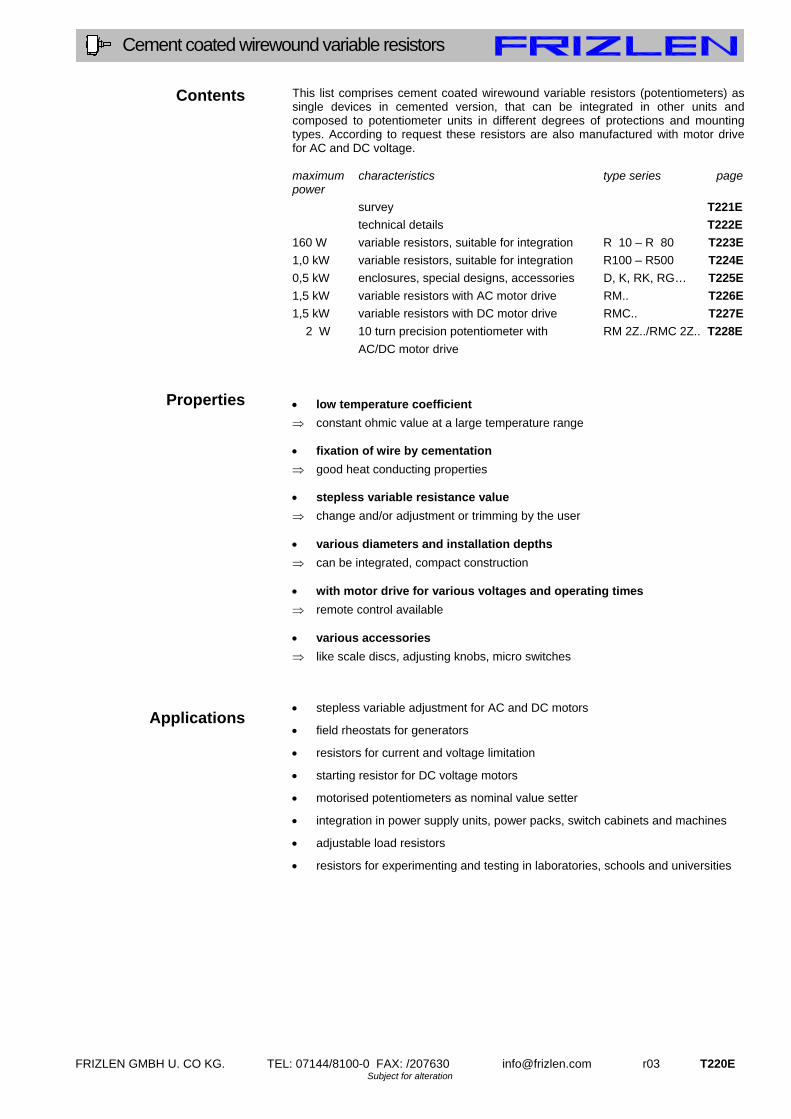
Cement coated wirewound variable resistors
Contents
Properties
Applications
This list comprises cement coated wirewound variable resistors (potentiometers) as single devices in cemented version, that can be integrated in other units and composed to potentiometer units in different degrees of protections and mounting types. According to request these resistors are also manufactured with motor drive for AC and DC voltage. maximum characteristics type series page power
survey T221E
technical details T222E
160 W variable resistors, suitable for integration R 10 – R 80 T223E
1,0 kW variable resistors, suitable for integration R100 – R500 T224E
0,5 kW enclosures, special designs, accessories D, K, RK, RG… T225E
1,5 kW variable resistors with AC motor drive RM.. T226E
1,5 kW variable resistors with DC motor drive RMC.. T227E
2 W 10 turn precision potentiometer with RM 2Z../RMC 2Z.. T228E
AC/DC motor drive
low temperature coefficient
constant ohmic value at a large temperature range
fixation of wire by cementation
good heat conducting properties
stepless variable resistance value
change and/or adjustment or trimming by the user various diameters and installation depths
can be integrated, compact construction with motor drive for various voltages and operating times
remote control available various accessories
like scale discs, adjusting knobs, micro switches
stepless variable adjustment for AC and DC motors
field rheostats for generators
resistors for current and voltage limitation
starting resistor for DC voltage motors
motorised potentiometers as nominal value setter
integration in power supply units, power packs, switch cabinets and machines
adjustable load resistors
resistors for experimenting and testing in laboratories, schools and universities

T221E r03 FRIZLEN GMBH U. CO KG. TEL: 07144/8100-0 FAX: /207630 [email protected] Subject for alteration
Cement coated wirewound variable resistors
T 200 - Survey
type series
characteristics
page
R10 R20
T223E
R40 R80
T223E
R100 R150
T224E
R250 R500
T224E
RG
T225E
RK
T225E
RM
T226E
RMC
T227E
RM 2Z
T228E
RMC 2Z
T228E
typical power from [W] 16 50 120 300 8 8 16 16 2 2
typical power up to [W] 60 160 360 1000 250 25 1500 1500 2 2
dustproof X
micro switch available X X X X X X X X
degree of protection IP00 X X X X X X X X
degree of protection IP20 X
integration
X X X X X X X X X
AC - motor drive X X
DC - motor drive X X
enclosure/ laboratory version X
symbol
Mot.
DC
IP
00
IP
20
Mot.
AC
E
Rights for improvements and modifications of our products reserved. Modifications, errors and misprints justify no claim for damages.
We refer to our terms of sales and delivery.

FRIZLEN GMBH U. CO KG. TEL: 07144/8100-0 FAX: /207630 [email protected] r03 T222E Subject for alteration
Cement coated wirewound variable resistors
Technical details
Construction
Continuous power rating
Air and creepage distances
Storage temperature/ Operation temperature/
Installation altitude
How to order
This list comprises cement coated wirewound variable resistors (potentiometer) with continuous dissipation from 16 W up to 500 W. The ring-shaped bodies are made from steatite. The wires and bands with a low temperature coefficient, which are used for the resistance winding, are made from CuNi 44 according to DIN 17 471, 46 460 and 46 461 (formerly WM 50) for low and medium ohmic values or from CrNi 6015 according to DIN 17 742 and 46 463 (formerly WM 110) for high ohmic values. They are wound on distance and fixed and protected by a layer or a special cement which also improves the heat dissipation. The wire windings with rated continuous dissipation of resistors from 16 W to 500 W are produced according to DIN 41 473, 41 475 and 41 476. All resistors are manufactured with 3 connections and isolated shaft and can be used as voltage divider and as series resistance. The standard types of sizes R 10, R 20, R 40 und R 80 are equipped with fast-on terminals 4,8 x 0,8; all the others with screw connections. The contacts are usually made of silver. A coppered carbon contact can be used for high ohmic values and frequent operations. The listed typical power values are valid during permanent operation and at a maximum ambient temperature of 40° C. They are valid under the condition that cooling air may enter incessantly and that the potentiometers are fixed onto metallic surfaces. If the resistors are fixed onto non-metallic surfaces, the power rates should be lowered to about 70% of the listed values. If the ambient temperature is essentially higher than 40° C, the typical power has to be reduced by 5% for any temperature rise of 10 K. In addition to the mentioned maximum and minimum ohmic values other values can be achieved if required. Air and creepage distances are rated according to IEC 664 (DIN EN 0110 part 1) for the overvoltage category III and degree of pollution 3 for grounded three-phase mains supplies up to 3 x 500 V. Testing voltage 2.5 kV AC. The test voltage between shaft and the connections (50 Hz AC voltage) is 1000 V for the ten turn precision potentiometer, 2000 V for R 10 and R 20, 2500 V for all other sizes. Do not conclude from the calculated relation between the rated power and the maximum producible ohmic value to the rated voltage! Storage temperature: - 40° C to 80° C Operation temperature: - 30° C to 40° C. If the ambient temperature is higher than
40°C, you have to decrease the continuous dissipation by 4% per 10 K temperature rise!
Installation altitude: 2000 m above sea level, you have to decrease the continuous dissipation for 10% per 1000 m altitude, maximum altitude 5000 m above sea level
Restrictions are for the type series RM.. because of the technical build-in devices. Operation temperature: - 20° C to 40° C When ordering resistors, following details should possibly be mentioned: size of resistor, ohmic value (serie E 12 preferably), tolerance of resistance, desired accessories like knob, switches or scale disc, special types, application, power length of shaft. If there are no given details for a resistor, we feel free to furnish according to our own ideas.

T223E r03 FRIZLEN GMBH U. CO KG. TEL: 07144/8100-0 FAX: /207630 [email protected] Subject for alteration
Cement coated wirewound variable resistors
Type series R10 / R20 R40 / R80
Cement coated wirewound variable resistors
size R10 R20 R40 R80 production range in ohm ± 10%
1,5- 10 k
2,2- 15 k
3,9- 27 k
1 – 33 k
typical power in W at 40° C ambient temperature
16 30 50 80
connections, fast-on (solderable) or on request screw connections M3 in special design(only R40,R80)
4,8 x 0,8
rotation angle, start to stop 290° 290° 300° 293° rotation angle over winding 272° 275° 285° 278° line of resistance linear slider silver contact excess temperature by nominal power ca. 260° C test voltage in kV, 50 Hz 2 2 2,5 2,5 weight approx. g 50 80 150 200
basic construction dim. R10 R20 R40 R80 standard shaft length measured from mounting plate is 35 mm
A 34 42 54 68 B 28 30 40 50 C 40 48 60 75 D 30 E M4
available special shaft lengths 18, 21, 24, 40 mm shaft length fitting to switches D30 and D41: 21 mm .
with attached micro switch with solder connections dim. R10 R20 R40 R80 change over contact 250 V~, 4 A (in special design fast-on connectors 6,3x0,8)
A 60 64 70 75 B1 55 55 66 73 B2 66 66 77 84 C 40 48 60 80 D 17 21 27 34
Rxx ML1 Rxx MR1 Rxx ML2 Rxx MR2
1-pol. left (dim. B1) 1-pol. right (dim. B1) 2-pol. left (dim. B2) 2-pol. right (dim. B2)
in 2fold in-line configuration dim. R10 R20 R40 R80 (on request also in 3, 4 or 5fold in-line configuration available)
A 34 42 54 68 B 66 71 91 119
RZ..
configuration of 2 equal resistors on 1 shaft C 40 48 60 80
example: 2 equal resistors (each R20), with equal ohmic values (each 1k):
type: RZ20-2x1k
en)
IP
00 E
R40
12M-0802-00-001
12M-0802-01-001
12M-0802-00-001
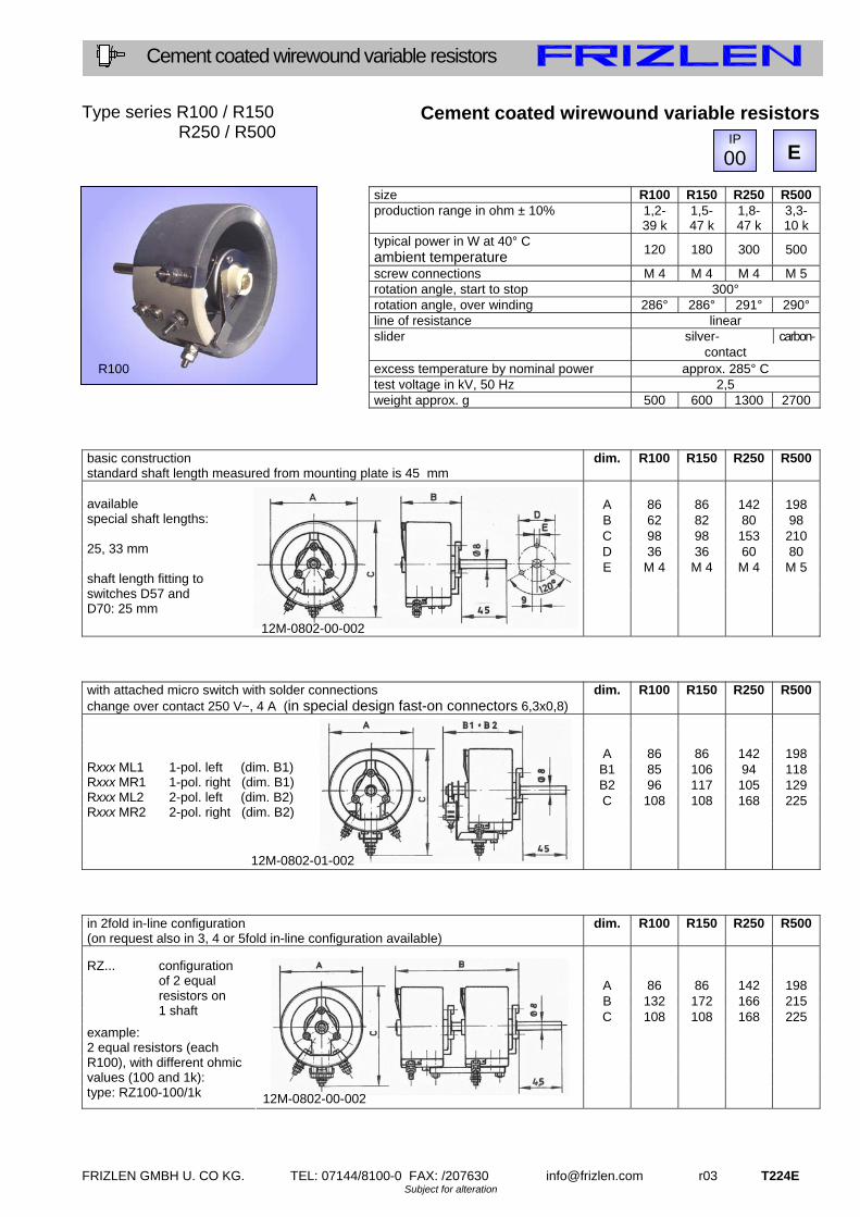
FRIZLEN GMBH U. CO KG. TEL: 07144/8100-0 FAX: /207630 [email protected] r03 T224E Subject for alteration
Cement coated wirewound variable resistors
Type series R100 / R150 R250 / R500
Cement coated wirewound variable resistors
size R100 R150 R250 R500 production range in ohm ± 10% 1,2-
39 k 1,5- 47 k
1,8- 47 k
3,3- 10 k
typical power in W at 40° C ambient temperature
120 180 300 500
screw connections M 4 M 4 M 4 M 5 rotation angle, start to stop 300° rotation angle, over winding 286° 286° 291° 290° line of resistance linear
silver- carbon- slider contact excess temperature by nominal power approx. 285° C test voltage in kV, 50 Hz 2,5
weight approx. g 500 600 1300 2700
basic construction dim. R100 R150 R250 R500 standard shaft length measured from mounting plate is 45 mm
A 86 86 142 198 B 62 82 80 98 C 98 98 153 210 D 36 36 60 80 E M 4 M 4 M 4 M 5
available special shaft lengths: 25, 33 mm shaft length fitting to switches D57 and D70: 25 mm
with attached micro switch with solder connections dim. R100 R150 R250 R500 change over contact 250 V~, 4 A (in special design fast-on connectors 6,3x0,8)
A 86 86 142 198 B1 85 106 94 118 B2 96 117 105 129 C 108 108 168 225
Rxxx ML1 Rxxx MR1 Rxxx ML2 Rxxx MR2
1-pol. left (dim. B1) 1-pol. right (dim. B1) 2-pol. left (dim. B2) 2-pol. right (dim. B2)
in 2fold in-line configuration dim. R100 R150 R250 R500 (on request also in 3, 4 or 5fold in-line configuration available)
A 86 86 142 198 B 132 172 166 215
RZ...
configuration of 2 equal resistors on 1 shaft C 108 108 168 225
example: 2 equal resistors (each R100), with different ohmic values (100 and 1k): type: RZ100-100/1k
R100
IP
00 E
12M-0802-00-002
12M-0802-01-002
12M-0802-00-002

T225E r03 FRIZLEN GMBH U. CO KG. TEL: 07144/8100-0 FAX: /207630 [email protected] Subject for alteration
Cement coated wirewound variable resistors
To type series R10 - R500
Enclosure, special designs, accessories
knob and scale disc for variable resistors R10 R40 R100 R250 R20 R80 R150 R500 knob – type D scale disc – type K type D 30 41 57 70
A 31 41 57 70 B 22 26 30 43
C 6 6 8 8 G 16 19 27 27 H 9 13 12 11
type K 28 38 55 68 E 10,5 10,5 8,5 8,5 F 48 65 80 100 L - - 4,5 4,5
M - - 36 44/60 type series RK…. dim. RK10
RK20 RK40
A 53 59 B 57 71
variable resistors dustproof encapsulated, maximal load 0,5 x typical power, with push-on connections 4,8 x 0,8 (solderable)
type series RG... dim. RG10
RG20 RG40
RG80 RG100 RG150
RG250 RG500
A 90 120 175 240 B 60 100 100 110 C 70 100 150 215 D 88 132 132 155
variable resistor, integrated in enclosure, with adjusting knob and scale disc, degree of protection IP 20, connections at the resistor maximal load 0,5 x typical power
special designs and accessories - zero position - locking device (only R10, R20, R40, R80, R100, R150) - screw driver slot (only R10, R20, R40, R80) - different shaft length - centre tap - reduced tolerance - sector winding (all sizes besides R10) - in laboratory version, please look at our list T400E
IP
00 E IP
20
12 M 0478
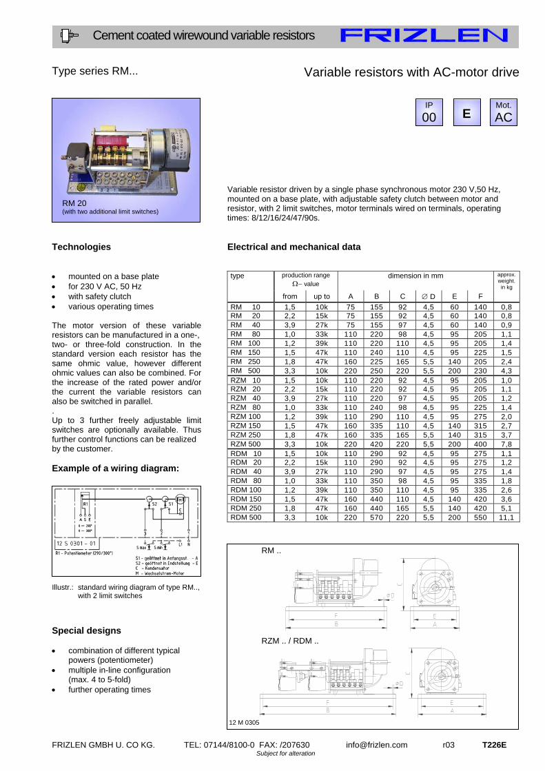
FRIZLEN GMBH U. CO KG. TEL: 07144/8100-0 FAX: /207630 [email protected] r03 T226E Subject for alteration
Cement coated wirewound variable resistors
Type series RM... Technologies mounted on a base plate for 230 V AC, 50 Hz with safety clutch various operating times The motor version of these variable resistors can be manufactured in a one-, two- or three-fold construction. In the standard version each resistor has the same ohmic value, however different ohmic values can also be combined. For the increase of the rated power and/or the current the variable resistors can also be switched in parallel. . Up to 3 further freely adjustable limit switches are optionally available. Thus further control functions can be realized by the customer. Example of a wiring diagram: Illustr.: standard wiring diagram of type RM..,
with 2 limit switches
Special designs combination of different typical
powers (potentiometer) multiple in-line configuration
(max. 4 to 5-fold) further operating times
Variable resistors with AC-motor drive Variable resistor driven by a single phase synchronous motor 230 V,50 Hz, mounted on a base plate, with adjustable safety clutch between motor and resistor, with 2 limit switches, motor terminals wired on terminals, operating times: 8/12/16/24/47/90s. Electrical and mechanical data
production range value
dimension in mm approx.weight. in kg
type
from up to A B C D E F
RM 10 1,5 10k 75 155 92 4,5 60 140 0,8RM 20 2,2 15k 75 155 92 4,5 60 140 0,8 RM 40 3,9 27k 75 155 97 4,5 60 140 0,9 RM 80 1,0 33k 110 220 98 4,5 95 205 1,1 RM 100 1,2 39k 110 220 110 4,5 95 205 1,4 RM 150 1,5 47k 110 240 110 4,5 95 225 1,5 RM 250 1,8 47k 160 225 165 5,5 140 205 2,4 RM 500 3,3 10k 220 250 220 5,5 200 230 4,3 RZM 10 1,5 10k 110 220 92 4,5 95 205 1,0RZM 20 2,2 15k 110 220 92 4,5 95 205 1,1 RZM 40 3,9 27k 110 220 97 4,5 95 205 1,2 RZM 80 1,0 33k 110 240 98 4,5 95 225 1,4 RZM 100 1,2 39k 110 290 110 4,5 95 275 2,0 RZM 150 1,5 47k 160 335 110 4,5 140 315 2,7 RZM 250 1,8 47k 160 335 165 5,5 140 315 3,7 RZM 500 3,3 10k 220 420 220 5,5 200 400 7,8 RDM 10 1,5 10k 110 290 92 4,5 95 275 1,1RDM 20 2,2 15k 110 290 92 4,5 95 275 1,2 RDM 40 3,9 27k 110 290 97 4,5 95 275 1,4 RDM 80 1,0 33k 110 350 98 4,5 95 335 1,8 RDM 100 1,2 39k 110 350 110 4,5 95 335 2,6 RDM 150 1,5 47k 160 440 110 4,5 140 420 3,6 RDM 250 1,8 47k 160 440 165 5,5 140 420 5,1 RDM 500 3,3 10k 220 570 220 5,5 200 550 11,1
RM ..
RZM .. / RDM ..
12 M 0305
RM 20 (with two additional limit switches)
IP
00 E Mot.
AC
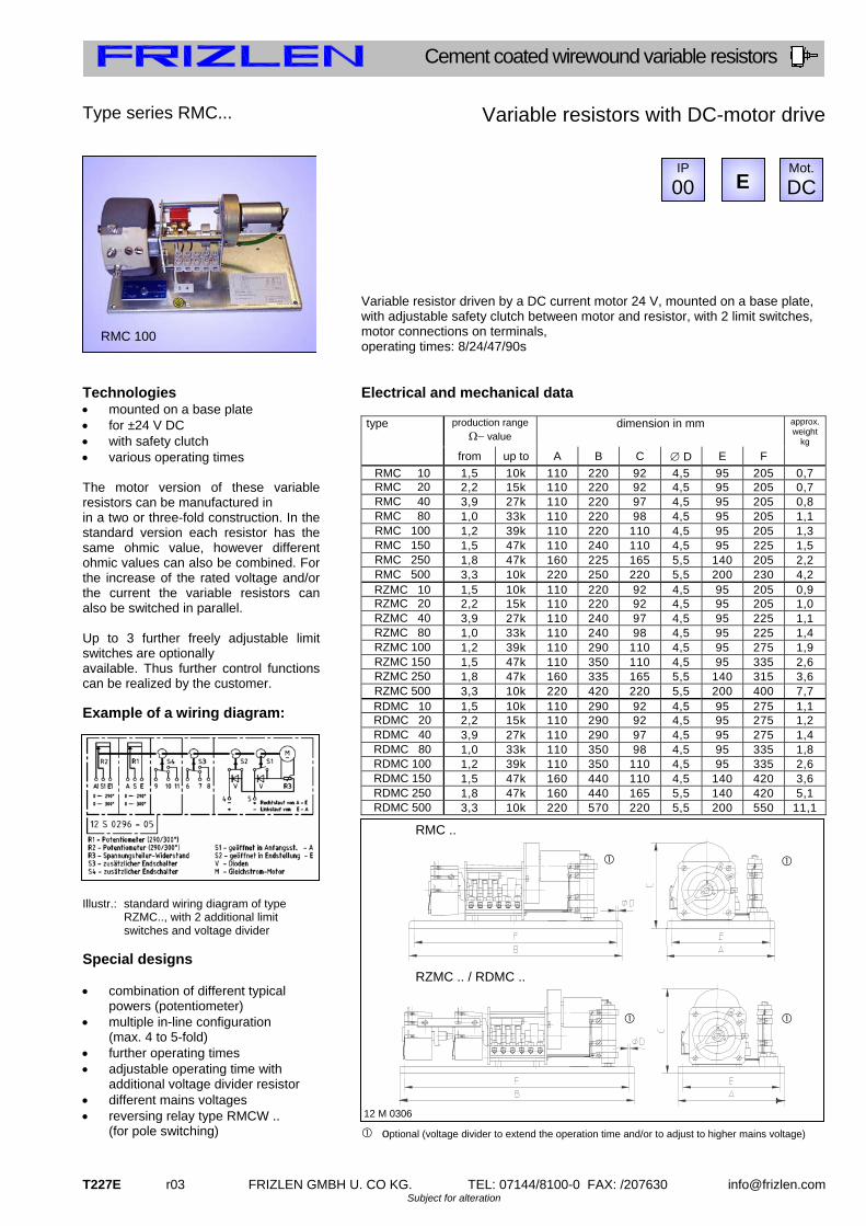
T227E r03 FRIZLEN GMBH U. CO KG. TEL: 07144/8100-0 FAX: /207630 [email protected] Subject for alteration
Cement coated wirewound variable resistors
Type series RMC... Technologies mounted on a base plate for ±24 V DC with safety clutch various operating times The motor version of these variable resistors can be manufactured in in a two or three-fold construction. In the standard version each resistor has the same ohmic value, however different ohmic values can also be combined. For the increase of the rated voltage and/or the current the variable resistors can also be switched in parallel. Up to 3 further freely adjustable limit switches are optionally available. Thus further control functions can be realized by the customer. Example of a wiring diagram: Illustr.: standard wiring diagram of type
RZMC.., with 2 additional limit switches and voltage divider
Special designs combination of different typical
powers (potentiometer) multiple in-line configuration
(max. 4 to 5-fold) further operating times adjustable operating time with
additional voltage divider resistor different mains voltages reversing relay type RMCW ..
(for pole switching)
Variable resistors with DC-motor drive Variable resistor driven by a DC current motor 24 V, mounted on a base plate, with adjustable safety clutch between motor and resistor, with 2 limit switches, motor connections on terminals, operating times: 8/24/47/90s Electrical and mechanical data
production range value
dimension in mm approx.weight
kg
type
from up to A B C D E F
RMC 10 1,5 10k 110 220 92 4,5 95 205 0,7RMC 20 2,2 15k 110 220 92 4,5 95 205 0,7 RMC 40 3,9 27k 110 220 97 4,5 95 205 0,8 RMC 80 1,0 33k 110 220 98 4,5 95 205 1,1 RMC 100 1,2 39k 110 220 110 4,5 95 205 1,3 RMC 150 1,5 47k 110 240 110 4,5 95 225 1,5 RMC 250 1,8 47k 160 225 165 5,5 140 205 2,2 RMC 500 3,3 10k 220 250 220 5,5 200 230 4,2 RZMC 10 1,5 10k 110 220 92 4,5 95 205 0,9RZMC 20 2,2 15k 110 220 92 4,5 95 205 1,0 RZMC 40 3,9 27k 110 240 97 4,5 95 225 1,1 RZMC 80 1,0 33k 110 240 98 4,5 95 225 1,4 RZMC 100 1,2 39k 110 290 110 4,5 95 275 1,9 RZMC 150 1,5 47k 110 350 110 4,5 95 335 2,6 RZMC 250 1,8 47k 160 335 165 5,5 140 315 3,6 RZMC 500 3,3 10k 220 420 220 5,5 200 400 7,7 RDMC 10 1,5 10k 110 290 92 4,5 95 275 1,1RDMC 20 2,2 15k 110 290 92 4,5 95 275 1,2 RDMC 40 3,9 27k 110 290 97 4,5 95 275 1,4 RDMC 80 1,0 33k 110 350 98 4,5 95 335 1,8 RDMC 100 1,2 39k 110 350 110 4,5 95 335 2,6 RDMC 150 1,5 47k 160 440 110 4,5 140 420 3,6 RDMC 250 1,8 47k 160 440 165 5,5 140 420 5,1 RDMC 500 3,3 10k 220 570 220 5,5 200 550 11,1
optional (voltage divider to extend the operation time and/or to adjust to higher mains voltage)
RMC ..
RZMC .. / RDMC ..
12 M 0306
RMC 100
IP
00 E Mot.
DC
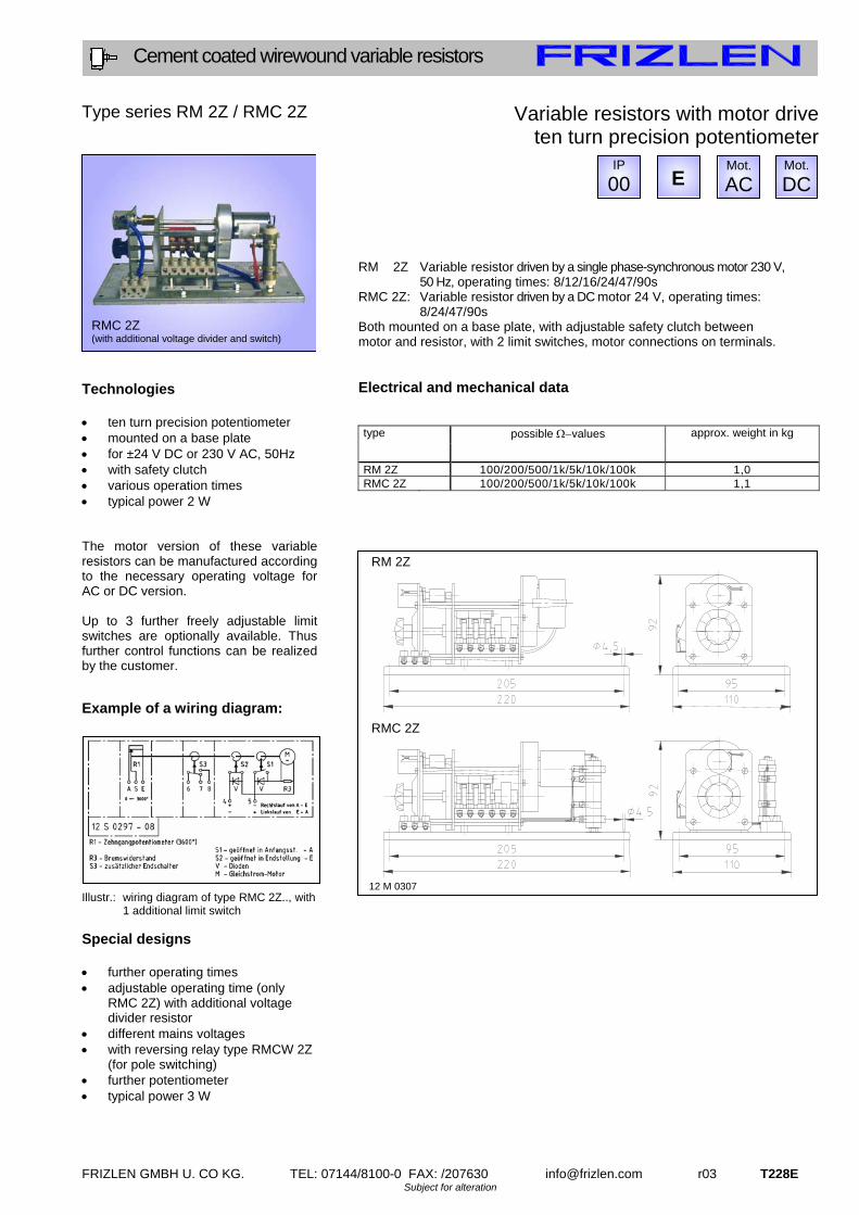
FRIZLEN GMBH U. CO KG. TEL: 07144/8100-0 FAX: /207630 [email protected] r03 T228E Subject for alteration
Cement coated wirewound variable resistors
Type series RM 2Z / RMC 2Z Technologies ten turn precision potentiometer mounted on a base plate for ±24 V DC or 230 V AC, 50Hz with safety clutch various operation times typical power 2 W The motor version of these variable resistors can be manufactured according to the necessary operating voltage for AC or DC version. Up to 3 further freely adjustable limit switches are optionally available. Thus further control functions can be realized by the customer. Example of a wiring diagram: Illustr.: wiring diagram of type RMC 2Z.., with
1 additional limit switch Special designs further operating times adjustable operating time (only
RMC 2Z) with additional voltage divider resistor
different mains voltages with reversing relay type RMCW 2Z
(for pole switching) further potentiometer typical power 3 W
Variable resistors with motor drive ten turn precision potentiometer
RM 2Z Variable resistor driven by a single phase-synchronous motor 230 V,
50 Hz, operating times: 8/12/16/24/47/90s RMC 2Z: Variable resistor driven by a DC motor 24 V, operating times:
8/24/47/90s Both mounted on a base plate, with adjustable safety clutch between motor and resistor, with 2 limit switches, motor connections on terminals. Electrical and mechanical data
possible values type
approx. weight in kg
RM 2Z 100/200/500/1k/5k/10k/100k 1,0RMC 2Z 100/200/500/1k/5k/10k/100k 1,1
RMC 2Z (with additional voltage divider and switch)
RM 2Z
RMC 2Z
12 M 0307
IP
00 E Mot.
ACMot.
DC

t100
t200
t300
t 3 0 0 – d i e i N N o v A t i v e N / t h e i N N o v A t i v e o N e s
drahtgewickelte Flachwiderstände 5 bis 40000 Watt
Drahtgewickelte Flachwiderstände als Einzelelemente, die einbau-
fähig sind und im Aluminiumgehäuse gekapselte Festwiderstände in
verschiedenen Schutz- und Befestigungsarten.
Anschluss an Litzen oder Lötpins, bei Einbau im Gehäuse
auch an Klemmen
Einzelwiderstände zu Baugruppen kombiniert für spezielle
Einbaulösungen in Schutzart IP00
Für waagerechte oder senkrechte Befestigung im Aluminium-
gehäuse bis Schutzart IP67, auch in Mehrfachanordnung
Für größere Leistungen in wassergekühlter Ausführung
bei Schutzarten bis IP54
Wirewound fl at resistors5 up to 40000 Watt
Wirewound fl at resistors as individual components in an open design
that can be integrated into other units and composed to incapsulated
fl at resistor units in different degrees of protection and mounting types.
With wires or soldering lugs, if enclosed connection to wires
or terminals
In degree of protection IP00 single elements can be combined
to units for special requirements
Up to degree of protection IP67 for horizontal and vertical
mounting, also in multiple confi guration
Watercooled for higher continuous dissipation up to degree
of protection IP54
www.fr iz len.com
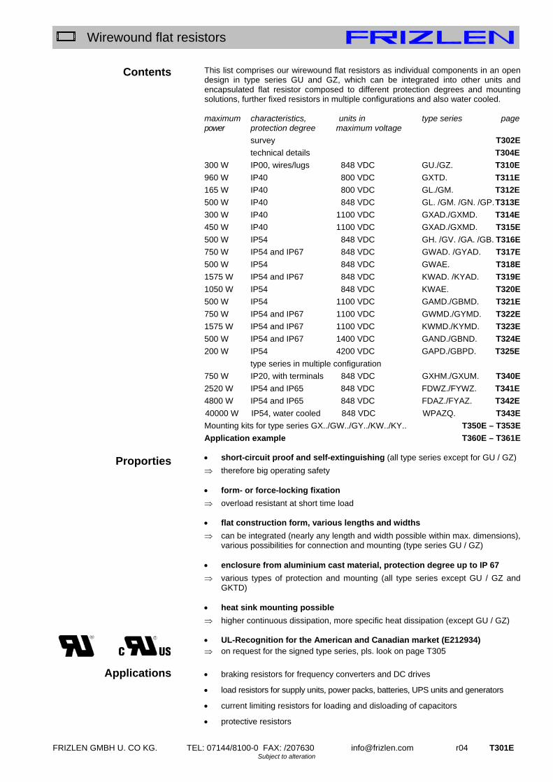
FRIZLEN GMBH U. CO KG. TEL: 07144/8100-0 FAX: /207630 [email protected] r04 T301E Subject to alteration
Wirewound flat resistors
Contents
Proporties
Applications
This list comprises our wirewound flat resistors as individual components in an open design in type series GU and GZ, which can be integrated into other units and encapsulated flat resistor composed to different protection degrees and mounting solutions, further fixed resistors in multiple configurations and also water cooled. maximum characteristics, units in type series page power protection degree maximum voltage
survey T302E
technical details T304E
300 W IP00, wires/lugs 848 VDC GU./GZ. T310E
960 W IP40 800 VDC GXTD. T311E
165 W IP40 800 VDC GL./GM. T312E
500 W IP40 848 VDC GL. /GM. /GN. /GP. T313E
300 W IP40 1100 VDC GXAD./GXMD. T314E
450 W IP40 1100 VDC GXAD./GXMD. T315E
500 W IP54 848 VDC GH. /GV. /GA. /GB. T316E
750 W IP54 and IP67 848 VDC GWAD. /GYAD. T317E
500 W IP54 848 VDC GWAE. T318E
1575 W IP54 and IP67 848 VDC KWAD. /KYAD. T319E
1050 W IP54 848 VDC KWAE. T320E
500 W IP54 1100 VDC GAMD./GBMD. T321E
750 W IP54 and IP67 1100 VDC GWMD./GYMD. T322E
1575 W IP54 and IP67 1100 VDC KWMD./KYMD. T323E
500 W IP54 and IP67 1400 VDC GAND./GBND. T324E
200 W IP54 4200 VDC GAPD./GBPD. T325E
type series in multiple configuration
750 W IP20, with terminals 848 VDC GXHM./GXUM. T340E
2520 W IP54 and IP65 848 VDC FDWZ./FYWZ. T341E
4800 W IP54 and IP65 848 VDC FDAZ./FYAZ. T342E
40000 W IP54, water cooled 848 VDC WPAZQ. T343E
Mounting kits for type series GX../GW../GY../KW../KY.. T350E – T353E
Application example T360E – T361E
short-circuit proof and self-extinguishing (all type series except for GU / GZ)
therefore big operating safety
form- or force-locking fixation
overload resistant at short time load
flat construction form, various lengths and widths
can be integrated (nearly any length and width possible within max. dimensions), various possibilities for connection and mounting (type series GU / GZ)
enclosure from aluminium cast material, protection degree up to IP 67
various types of protection and mounting (all type series except GU / GZ and GKTD)
heat sink mounting possible
higher continuous dissipation, more specific heat dissipation (except GU / GZ)
UL-Recognition for the American and Canadian market (E212934) on request for the signed type series, pls. look on page T305
braking resistors for frequency converters and DC drives
load resistors for supply units, power packs, batteries, UPS units and generators
current limiting resistors for loading and disloading of capacitors
protective resistors

T302E r04 [email protected] FRIZLEN GMBH U. CO KG. TEL: 07144/8100-0 FAX: /207630 Subject to alteration
Wirewound flat resistors
symbol
T 300 – survey – single resistors up to 1100 V DC
type series characteristics
page
GU +
GZ
T310E
GXTD
T311E
GLAD +
GMAD
T312E
GLAD GMADGNADGPAD
T313E
GXAD GXMD
T314E +
T315E
GHADGVAD GAAD GBAD
T316E
GWAD GYAD
T317E
GWAE
T318E
KWAD+
KYAD
T319E
KWAE
T320E
typical power from [W] 5 30 40 50 100 50 100 100 150 150
typical power up to [W] 300 960 165 500 450 500 750 500 1575 1050
degree of protection IP00 X
degree of protection IP40 X X X X
degree of protection IP54 X X X X X
degree of protection IP67 X X
horizontal mounting X X X X X X X X X
vertical mounting X X X X X X X X X
can be integrated X X X X X X X X X X
temperature switch (optional)
X X X X X
max. voltage 800 VDC X X
max. voltage 848 VDC X X X X X X X X
max. voltage 1100 VDC X
max. voltage 1400 VDC
max. voltage 4200 VDC
X X X X X X X
X
X
Rights for improvements and modifications of our products reserved. Modifications, errors and misprints justify no claim for damages.
We refer to our terms of sales and delivery.
IP
67
1100V DC
800V DC
848V DC
with Recognition
IP
40
IP
00
E
with Recognition
1400V DC
4200V DC
IP
54
IP
67

FRIZLEN GMBH U. CO KG. TEL: 07144/8100-0 FAX: /207630 [email protected] r04 T303E Subject to alteration
Wirewound flat resistors
symbol
T 300 – survey – single resistors up to 4,2 kV DC and in multiple configurations
type series characteristics
page
GAMD +
GBMD
T321E
GWMD+
GYMD
T322E
KWMD +
KYMD
T323E
GAND +
GBND
T324E
GAPD +
GBPD
T325E
GXHM +
GXUM
T340E
FDWZ +
FYWZ
T341E
FDAZ +
FYAZ
T342E
WPAZQ
T343E
typical power from [W] 110 100 150 110 200 100 225 160 10k
typical power up to [W] 500 750 1575 500 300 750 2520 4800 40k
degree of protection IP40 X
degree of protection IP54 X X X X X X X X
degree of protection IP65 X X
degree of protection IP67 X X
horizontal mounting X X X X X X X X X
vertical mounting X X X X X X X X X
can be integrated X X X X X X X
temperature switch (optional)
X X X X X X X X
max. voltage 800 VDC
max. voltage 848 VDC X X X X
max. voltage 1100 VDC X X X
max. voltage 1400 VDC X
max. voltage 4200 VDC X
X
X X X X
Rights for improvements and modifications of our products reserved. Modifications, errors and misprints justify no claim for damages.
We refer to our terms of sales and delivery.
800V DC
848V DC
1100V DC
IP
54
IP
40
E
with Recognition
IP
67
with Recognition
4200V DC
1400V DC
IP
65

T304E r04 [email protected] FRIZLEN GMBH U. CO KG. TEL: 07144/8100-0 FAX: /207630 Subject to alteration
Wirewound flat resistors
Technical details
Construction
Resistance values/ Production tolerance/
Temperature dependency
Degrees of protection
Time constant
Wiring / Connections
Wirewound flat resistors consist of support straps and wiring. As standard version the support strap is made of mica. For resistor windings we use round wires consist of alloy CuNi 44 according to DIN 17471, 46460-1 and 46461 or of NiCr 3020 or CrAl 25 5 according to DIN 17470. We either wind an oxidized wire without gap (type GU) or fix them by non-slip strip cementing (type GZ), even if they lengthen a little when heated. We surround the resistor installations of our encapsulated flat resistors with quartz sand. Then the wire will not slip and the heat transfer to the aluminium enclosure is reliable.
The resistance values in the column “production range“ refer to the standard production program, further values on request. The normal tolerance is 10%, restricted tolerance on request. The resistance value slightly changes in dependency of the winding temperature. The temperature rise at the winding is T 300 K when the rated power is operating continuously. Compared to the cooled off condition you have the following changes of resistance value: with wires made of CuNi 44 approx. ±1%, of CrAl 25 5 approx. +1% and of NiCr 3020 approx. +10%.
Correlation of type series and degrees of protection according to EN 60529 and/or DIN VDE 0470 part 1. Type series
Degree of protection
First digit: Degree of protection against access & against solid foreign objects
Second digit: Degree of protection against water
GU GZ
IP 00 Non-protected – i.e. depending upon integration the user must provide a protection
Non-protected
GLAD GMAD GNAD GPAD GX..
IP 40
Protected against access to hazardous parts with a wire and against solid foreign objects of 1 mm and greater.
Non-protected
GA.. GB.. GHAD GVAD GW.. KW..
IP 54 Protected against access to hazardous parts with a wire and against dust
Protected against splashing water. Water splashed against the enclosure from any direction shall have no harmful effects
GY.. KY..
IP 67 Protected against access to hazardous parts with a wire and dust-tight
Protected against the effects of temporary immersion in water. Ingress of water in quantities causing harmful effects shall not be possible when the enclosure is temporarily immersed in water under standardized conditions of pressure and time
Devices with degrees of protection IP 20 or higher comply with the CE low voltage directive. Power resistors being passive electronical or electrical units are not affected by the specific EMC standards. They do not produce any interfering radiation nor are they affected.
The average thermal time constant is 360 sec. under the condition of free mounting and cooling.
All our encapsulated resistors in standard version have UL recognized FEP/PTFE-wires, that are partially also wired on terminals. (Special wire insulations on request). If the wiring is accomplished by the customer, make sure that a heat resistant wire is used!
IP
00
IP
40
IP
54
IP
67

FRIZLEN GMBH U. CO KG. TEL: 07144/8100-0 FAX: /207630 [email protected] r04 T305E Subject to alteration
Wirewound flat resistors
Air- and creepage distances/
UL-Recognition
Excess temperature protection
Contact ratings
Storage temperature/ Operation temperature/
Installation altitude
Typical power/
Continuous dissipation/ Ventilation/
Temperatures
All standard type series can be delivered in a version with UL-Recognition and are rated for the overvoltage category III, the air and creepage distances are rated according to IEC 664 (DIN VDE 0110 part 1). For protection degree IP40 the resistors are rated for pollution level 2, versions with protection degree IP 54 and higher are for pollution level 3. These data are valid for all devices that are connected with mains voltage and derived voltages, as for example the intermediate circuit voltage of frequency converters. The type of authorisation and the underlained three-phase main voltage are given in the survey. Type of authorisation (E212934)
Authorisation up to
Grounded three- phase mains up to
Grounded and ungrounded three- phase mains up to
Testing voltage
(CSA C22.2 No.14)
800 VDC 3 x 277/400 VAC 3 x 277 VAC 4,2 kV DC
(CSA C22.2 No.14)
848 VDC 3 x 347/600 VAC 3 x 600 VAC 4,2 kV DC
1100 VDC 3 x 400/690 VAC 3 x 690 VAC 4,2 kV DC
1400 VDC 3 x 480/830 VAC 3 x 1000 VAC 4,2 kV DC
(Please ask for it or download it: www.frizlen.com). A version of the excess temperature monitoring particularly suited for long-term overloading is to equip with a temperature switch with two wires. It opens a signal contact when the set temperature is exceeded. The resistor is not switched off. You can inform yourselfs about function and restrictions by our data sheet „Tripping of monitoring device“. Contact ratings of the signal contact: 6,3 A / 230 VAC (cos phi = 0,6) resp. 2,0 A / 24 VDC Storage temperature: - 40° C to 80° C Operation temperature: - 30° C to 40° C. If the ambient temperature is higher than
40°C, you have to decrease the continuous dissipation by 4% per 10 K temperature rise!
Installation altitude: 2000 m above sea level, you have to decrease the continuous dissipation for 10% per 1000 m altitude, maximum altitude 5000 m above sea level
The given typical power values are valid for 100% duty cycle factor (DCF) (continuous dissipation) under the following conditions: temperature rise of 200 K at the surface of fixed resistors (degree of protection>
IP00) temperature rise of 300 K at the surface of fixed resistor elements (degree of
protection IP00). unhindered access of cooling air unhindered diverting of warmed up air (keep a minimum separation distance of
approx. 200 mm to neighbouring components/walls and of approx. 300 mm to components above/ceiling)

T306E r04 [email protected] FRIZLEN GMBH U. CO KG. TEL: 07144/8100-0 FAX: /207630 Subject to alteration
Wirewound flat resistors
Ventilation / temperatures
Since electrical energy is converted into heat, it is inevitable that the exhaust air will be heated up, as well as the section of enclosure at the surface. The highest temperature with typical power may be maximum 200°C above the ambient temperature. Since the cooling of the devices is accomplished by convection, the above mentioned aspects have absolutely to be considered. In case of insufficient cooling or false mounting the resistor or the surrounding devices could be overheated or ruined. Depending upon use it can be possible, to increase the continuous dissipation of the resistors, if higher temperatures are accepted. With increase e.g. of 130% of the typical power you will have a rise in temperature of 350K at the surface of the resistor. In other cases of applications the continuous dissipation must be reduced, for example with temperature sensitive devices in the surrounding. The dependence between temperature rise and actual continuous dissipation is shown in the diagram below.
Normal operation range (up to 130%):
Recommended operation range for maximum product life and failure free operation Allowable threshold (up to 160%):
Allowable operation range, danger of shorter product life and higher failure probability Unallowable operation range (more than 160%):
Danger of excessive heat and destruction of resistor and neighbouring components
Excess temperature in dependence of continuous dissipation
0
1 0 0
2 0 0
3 0 0
4 0 0
5 0 0
0 5 0 1 0 0 1 5 0 2 0 0 2 5 0
D a u e r le is tu n g in % d e r T y p le is tu n g
Üb
erte
mp
erat
ur
[K]
normal operation range
allowable threshold unallowable operation range
at the resistor element type GU/GZ
continuous dissipation in % of the typical power
exce
ss t
em
per
atu
re [
K]
at the enclosure surface

FRIZLEN GMBH U. CO KG. TEL: 07144/8100-0 FAX: /207630 [email protected] r04 T307E Subject to alteration
Wirewound flat resistors
Short time dissipation/ Total cycle time/
Duty cycle factor(DCF )
Overload factor(OLF)
Calculation example given:
wanted:
continuous dissipation
In many applications resistors are not loaded in continuous but in short time operation. In the following you will find indications, how to calculate the allowable short time dissipation with the help of the duty cycle factor (DCF) and the overload factor (OLF). If the DCF factor is not known, it can be calculated as follows:
Warning: The total cycle time may be maximum 120 s - shorter total cycle times are possible. The total cycle times for motors are mostly higher than 120 s By comparison of the known DCF-factor with the following diagram or table you can work out the overload factor (OLF) and/or the continuous and the short time dissipation.
DCF 1% 3 % 6% 15% 25% 40% 60% 80% 100% OLF 22 13 8,2 4,2 3,0 2,2 1,5 1,12 1,0
The continuous and the short time dissipation can be calculated as follows:
Resistor with a short time dissipation of 2,5 kW for 7 s and a total cycle time of 120s
The duty cycle factor (DCF) is 7 s : 120 s x 100% = 6% Overload factor (OLF) for 6% DCF, according to table it is 8,2 The continuous dissipation is 2,5 kW : 8,2 = 305 W; You need a resistor with a continuous dissipation of at least 300W e.g. type GWAD/GYAD 320x80
%404,0.120
481
s
sDCF
Total cycle time = 120 s
ton = 48 s
Total cycle time = 30 s
ton = 7,5 s
%2525,030
5,72
s
sDCF
Overload factor (OLF) in dependence of duty cycle factor (DCF)(Total cycle time 120s)
DCF
OLF
- o
f fla
t typ
e re
sist
ors
1% 6% 10% 25% 40% 60% 100%
20
10
3
1
timecycleTotal
ttimeonSwitchDCFfactorcycleDuty on)(
OLFfactorOverload
ndissipatiotimeShortndissipatioContinuous
OLFndissipatioContinuousndissipatiotimeShort

T308E r04 [email protected] FRIZLEN GMBH U. CO KG. TEL: 07144/8100-0 FAX: /207630 Subject to alteration
Wirewound flat resistors
Terminal details/ wire cross-section
Mounting
Rated current and cross section of terminals: Type Abbreviation Rated
current in A with 100%
DCF
Rated current in A up to 40%
DCF
Maximum cross section
porcelain-terminal
PK 16 up to 2,5 mm²
G 5 30 38 0,5 – 2,5 (4) mm²
AWG 24 - 12 Device terminals out of polyamid (PA) G 10 60 75
0,5 – 10 (16) mm² AWG 20 - 6
ST2,5 20 25 up to 2,5 (4) mm²;
AWG 28 - 12
ST 4 30 38 up to 4,0 (6) mm²;
AWG 28 – 10
ST 6 41 52 up to 6 (10) mm²;
AWG 24 - 8
cage clamp terminal out of PA
ST 10 57 72 up to 10 (16) mm²;
AWG 24 – 6 The values in brackets are for solid conductors or for single wiring. More terminal types on request or on demand. The rated current is calculated in each case due to the Ohm`s law as follows:
whereas P is the power of the resistor and R is the value of the resistance
Please mind the mounting indications in the respective series! You will find these icons in the data sheets: Allowable: On horizontal surfaces Allowable: On vertical surfaces terminals/wires at the bottom Not allowable: On vertical surfaces terminals/wires at the top, left or right.
R
PI

FRIZLEN GMBH U. CO KG. TEL: 07144/8100-0 FAX: /207630 [email protected] r04 T310E Subject to alteration
Wirewound flat resistors
Type series GU.. / GZ.. Technologies superflat construction form practically any length or width
possible within maximum dimensions
extremely adjustable to the given space
outstandingly appropriate for integration
high pulse power ratings of versions with insulating oxidized wire
Application An important application is the use as internal braking resistors as well as series resistors for current limiting when charging the intermediate circuit capacitors of frequency converters. These resistors are fitting extremely well into the given space. Further application as load or protective resistor. Special designs low noise and low induction with centre taps, i.e.. with several
partial resistors on one strap
5 – 300 W, IP 00, connection at wires or soldering lugs Wirewound mica flat resistor, degree of protection IP00. Maximum width up to 115 mm, maximum length up to 300 mm. Depending upon version either wired with blank (GZ..) or with insulating-oxidized wire (GU..). We fix the blank wire of the standard version by an additional strip of cementing.
optional, type designation would be GZU.. or GUU, e.g. GZU 110x40 - 20 Connection types and versions Version G...x.. D; (Illustr. s. middle left column, illustr. above) mica flat resistor with connection at 2 hard soldered wires D1 and D2. Version G...x.. L; (Illustr. s. middle left column, illustr. below) mica flat resistor with 2 soldering lugs (optionally double soldering lugs) as connection points, prepared to be soldered into a printed circuit board. Dimensioning Power per wire wound space is valid for a surface excess temperature of 200 K The total power of a mica flat resistor depends upon the wire wound space.
You can calculate as follows: BCA (dim. in mm)
The total power is therefore APP (power in W) You can calculate the total length as follows :
With B ≥ 33mm: mmCL 18 , with B ≤ 32mm: mmCL 48 The values of P´ for short time operation (depending upon DCF) amount to: DCF 100% 60% 40% 25% 15% 6% P´ (W/mm²) 0,02 0,03 0,044 0,06 0,084 0,164 These overload factors are valid for a total cycle time of maximum120 s!
Example of dimensioning and selection of a specific unit:
braking resistor for frequency converter for integration into an enclosure, connection at wires; for short time operation of 180 W at 25% DCF and a total cycle time of 120 s; resistance value 100 ; calculation of the necessary space: A = 180 W : 0,06 W/mm² = 3000 mm²; the winding length at a supposed width of 50 mm is 60 mm (3000 mm² : 50 mm). The total length would be 78 mm (60+18 mm distance from edge); type designation would be: GZ 78x50D-100; connection at 2 wires SIF 1,5 mm², each 200 mm long, equipped with conductor sleeves. Resistor rated for 180 W at 25 % DCF, which complies with a continuous dissipation of 60 W
GZ 78 x 50 D - 100 D1=D2=200mm 1,5mm² SIF with conductor limit coverings.
ohmic value 10% connection at wires (D) width B total length L type series (blank winding with strip
cementing)
D1 D2
Total length L in mm
Wid
th B
in
mm
7 mm
Winding length C in mm
GZ 100x33 L
IP
00 E
²0,2
²02,0
cm
W
mm
WP
848V DC

T311E r04 [email protected] FRIZLEN GMBH U. CO KG. TEL: 07144/8100-0 FAX: /207630 Subject to alteration
Wirewound flat resistors
Type series GXTD
Technologies superflat construction form, max.
5,0 mm practically any length or width
possible within the maximum dimensions
extremely adjustable to the given space
outstandingly appropriate for integration
higher continuous dissipation by mounting directly onto heat sink or cooling surface
test voltage for type GXTD is 2,5 kV test voltage for optional type GKTD
up to 7,7 kV Application An important application is the use as internal braking resistors as well as series resistors for current limiting when charging the intermediate circuit capacitors of frequency converters. These resistors are fitting extremely well into the given space. An additional application is the usage as heat resistor. Special design enclosure made of stainless steel connections according to customer
wishes, faston receptable, cable lug etc.
different length of the wires
30 – 960 W, IP 40, with enclosure Wirewound flat resistor, degree of protection IP 40. Maximum width up to 200 mm, maximum length up to 400 mm. Standard version with aluminium-zink enclosure. With 2 FEP-wires, AWG 18 (0,79 mm²), 0,3 m long. Versions Standard - design GXTD ..x.. Wirewound mica flat resistor, performed for a test voltage of 2,5 kV, for a DC voltage up to 800 VDC. At the moment in preparation: Design GKTD ..x.. Wirewound mica flat resistor, performed for a test voltage of 7,7 kV, for a DC voltage up to 848 VDC. Dimensioning
The power per space is
²20,1
²012,0
cm
W
mm
WP
The total power of a mica flat resistor depends upon the wire wound space A.
The total power is therefore: APP (power in W)
You can calculate as follows: BLA (dim. in mm) Example of dimensioning and selection of a specific unit:
Braking resistor for frequency converter for integration into an enclosure, connection with wires; resistance value 100 ; continuous dissipation 100 Watt, you can calculate the dimensions: A = P/P’= 100 W : 0,012 W/mm² = 8333 mm². Taking a length with L=100 mm, you receive the width B=A/L= 8333 mm² :100 mm = 83 mm. So you get the width B 84 mm rounded and a given length L 100 mm. Type designation for standard-design 2,5 kV test voltage, type is GXTD 100x84-100; connection at 2 wires AWG 18, each 300 mm long.
GXTD 100 x 84 - 100
ohmic value 10%
width B total length L type series
length L in mm
wid
th B
in
mm
5 mm
GXTD 100x84
IP
40 800V DC

FRIZLEN GMBH U. CO KG. TEL: 07144/8100-0 FAX: /207630 [email protected] r04 T312E Subject to alteration
Wirewound flat resistors
Type series GLAD, GMAD,
GMAD Technologies compact construction form in a
rectangular profile with rib-shaped cooling
short-circuit proof self-extinguishing degree of protection IP 40 higher continuous dissipation by
mounting directly onto heat sink or cooling surface
By mounting directly onto an appropriate cooling surface or onto a heat sink the continuous dissipation can be increased resp. the surface temperature can be lowered. Typical factors for an increase are 1,5 up to 5, depending on type, ventilation and size of the cooling surface or heat sink. Application Different applications derive from the various dimensions in width, height and length. An important application is the use as braking resistor for motor/generator drive of motors with frequency converters. Because of their degree of protection the resistors can perfectly be integrated into frequency converters or switch cabinets.
40 – 165 W, IP 40, profile x34 and x13
Short-circuit proof wirewound flat resistor, degree of protection IP 40 in blank aluminium enclosure. Design with 2 PTRadox-wires, AWG 18/19 (0,82 mm²), 0,5 m long.
There are 4 versions available: horizontal – type series GLAD vertical – type series GMAD
optionally, type designation would be G.ADU.., e.g. GLADU 207x34 - 100
Electrical and mechanical data
continuous dissipation in W at 40°C,
100%DCF and surface excess temperature of
production range
value
dimensions in mm weight in g
Type
200 K typical -power
250 K from up to A B C D G H J
GLAD 100x34 40 60 1,0 3,3k 100 50 34 13 1,5 88 4,5 100GLAD 180x34 85 125 1,5 4,7k 180 50 34 13 1,5 168 4,5 150 GLAD 207x34 100 150 2,2 6,8k 207 50 34 13 1,5 195 4,5 180 GLAD 230x34 110 165 3,3 10k 230 50 34 13 1,5 218 4,5 200 GMAD 100x13 40 60 1,0 3,3k 100 65 34 13 1,5 88 4,5 100 GMAD 180x13 85 125 1,5 4,7k 180 65 34 13 1,5 168 4,5 150 GMAD 207x13 100 150 2,2 6,8k 207 65 34 13 1,5 195 4,5 180 GMAD 230x13 110 165 3,3 10k 230 65 34 13 1,5 218 4,5 200
The given power rating values are valid for 100%CD (continuous dissipation). For short time operation you will find the values in the following table as a function of the duty cycle factor (DCF). Just multiply by the corresponding overload factor (OLF). (Also see pages T306E and T307E). ED 60% 40% 25% 15% 6% 3% 1% ÜF 1,5 2,2 3,0 4,2 8,2 13 22
These overload factors are valid for a total cycle time of maximum 120 s. GLAD…
13 M 0573
GLAD 207 x 34
IP
40
GMAD...
13 M 0663
800V DC GMAD 180 x 13

T313E r04 [email protected] FRIZLEN GMBH U. CO KG. TEL: 07144/8100-0 FAX: /207630 Subject to alteration
Wirewound flat resistors
Type series GLAD, GMAD, GNAD, GPAD Technologies compact construction form in a
rectangular profile short-circuit proof self-extinguishing degree of protection IP 40 higher continuous dissipation by
mounting directly onto heat sink or cooling surface
By mounting directly onto an appropriate cooling surface or onto a heat sink the continuous dissipation can be increased resp. the surface temperature can be lowered. Typical factors for an increase are 1,5 up to 5, depending on type, ventilation and size of the cooling surface or heat sink. Option: temperature switch (..Q) This type can be fitted with a 180° C temperature switch for monitoring, which has 2 connection wires.
Type designation would be: G.ADQ ... Application Different applications derive from the various dimensions in width, height and length. We provide e.g. 4 different constructions forms for 155 W. An important application is the use as braking resistor for motor/generator drive of motors with frequency converters. Because of their degree of protection the resistors can perfectly be integrated into frequency converters or switch cabinets.
50 – 500 W, IP 40, profile x40, x20, x60 and x30
Short-circuit proof wirewound flat resistor, degree of protection IP 40 in blank aluminium enclosure. Design with 2 wires 0,5 m long. Type series: GLAD, GMAD with 2 Radox-wires, AWG 18/19 (0,82 mm²) Type series: GNAD, GPAD with 2 FEP-wires, AWG 14/19 (1,9 mm²)
There are 2 versions available: horizontal – type series GLAD, GNAD vertical – type series GMAD, GPAD
optionally, type designation would be G.ADU.., e.g. GLADU 210x40 - 100
Electrical and mechanical data
continuous dissipation in W at 40°C,
100%DCF and surface excess temperature of
production range
value
dimensions in mm weight in g
Type series
200 K typical -power
250 K from up to A B C D G H J
GLAD 100x40 50 75 1,0 3,3k 100 45 40 20 2 82 4,3 145GLAD 150x40 65 100 1,5 4,7k 150 45 40 20 2 132 4,3 215 GLAD 210x40 100 150 2,2 6,8k 210 45 40 20 2 192 4,3 300 GLAD 240x40 120 180 3,3 10k 240 45 40 20 2 222 4,3 340 GLAD 300x40 155 235 4,7 15k 300 45 40 20 2 282 4,3 430 GLAD 360x40 190 285 5,6 18k 360 45 40 20 2 342 4,3 515 GMAD 100x20 50 75 1,0 3,3k 100 65 20 40 2 82 4,3 145 GMAD 150x20 65 100 1,5 4,7k 150 65 20 40 2 132 4,3 215 GMAD 210x20 100 150 2,2 6,8k 210 65 20 40 2 192 4,3 300 GMAD 240x20 120 180 3,3 10k 240 65 20 40 2 222 4,3 340 GMAD 300x20 155 235 4,7 15k 300 65 20 40 2 282 4,3 430 GMAD 360x20 190 285 5,6 18k 360 65 20 40 2 342 4,3 515 GNAD 165x60 110 165 2,2 6,8k 165 60 60 30 3 146 5,3 590 GNAD 215x60 155 235 3,3 10k 215 60 60 30 3 196 5,3 770 GNAD 265x60 200 300 4,7 15k 265 60 60 30 3 246 5,3 950 GNAD 335x60 270 400 6,8 22k 335 60 60 30 3 316 5,3 1200 GNAD 405x60 330 500 8,2 27k 405 60 60 30 3 386 5,3 1450 GPAD 165x30 110 165 2,2 6,8k 165 73 30 60 3 146 5,3 590 GPAD 215x30 155 235 3,3 10k 215 73 30 60 3 196 5,3 770 GPAD 265x30 200 300 4,7 15k 265 73 30 60 3 246 5,3 950 GPAD 335x30 270 400 6,8 22k 335 73 30 60 3 316 5,3 1200 GPAD 405x30 330 500 8,2 27k 405 73 30 60 3 386 5,3 1450
The given power rating values are valid for 100%CD (continuous dissipation). For short time operation you will find the values in the following table as a function of the duty cycle factor (DCF). Just multiply by the corresponding overload factor (OLF). (Also see pages T306E and T307E). ED 60% 40% 25% 15% 6% 3% 1% ÜF 1,5 2,2 3,0 4,2 8,2 13 22
These overload factors are valid for a total cycle time of maximum 120 s.
GLAD, GMAD, GNAD, GPAD... (the figure shows the version with temperature switch (Q))
13 M 0446
GLAD 210 x 40
GMAD 150 x 20 848V
DC
IP
40

FRIZLEN GMBH U. CO KG. TEL: 07144/8100-0 FAX: /207630 [email protected] r04 T314E Subject to alteration
Wirewound flat resistors
Type series GXAD / GXMD
Technologies rated voltage max.1100 VDC very flat, compact construction form short-circuit proof self-extinguishing degree of protection IP 40 higher continuous dissipation by
mounting directly onto heat sink or cooling surface
compact construction form By mounting directly onto an appropriate cooling surface or onto a heat sink the continuous dissipation can be increased resp. the surface temperature can be lowered. Typical factors for an increase are 1,5 up to 5, depending on type, ventilation and size of the cooling surface or heat sink. Application E.g. as brake-resistor for frequency converters (fc). Based on the small sizes these resistors can be mounted directly to the housing of a fc. Special design E.g. with higher protection degree
IP54/67
You will find further examples on page T317E.
100 – 300 W, IP 40, profile x70
Short-circuit proof wirewound flat resistor, in blank aluminium enclosure. With different sizes and for different voltages.PT Design with 2 PTFE-wires, AWG 14/19 (mind. 1,9 mm²), 0,5 m long. Type series: GXAD.. rated voltage max. 848 VDC Type series: GXMD.. rated voltage max. 1100 VDC
optionally with different UL - certification, see page T305E, type designation would be GX.DU.., e.g. GXADU 216x70 - 33 Electrical and mechanical data
continuous dissipation in W at 40°C, 100%DCF
and surface excess temperature of
production range value
dimensions in mm
weight in g
Type series GXAD – 848 V GXMD – 1100 V
200 K typical power
250 K from up to A B
GX.D 110 x 70 100 150 2,7 3,3k 110 98 300GX.D 160 x 70 150 225 4,7 5,6k 160 148 420 GX.D 216 x 70 200 300 6,8 8,2k 216 204 550
The given power rating values are valid for 100%CD (continuous dissipation). For short time operation you will find the values in the following table as a function of the duty cycle factor (DCF). Just multiply by the corresponding overload factor (OLF). (Also see pages T306E and T307E). ED 60% 40% 25% 15% 6% 3% 1% ÜF 1,5 2,2 3,0 4,2 8,2 13 22
These overload factors are valid for a total cycle time of maximum 120 s. Example of dimensioning and selection of a specific unit:
Braking resistor for frequency converter drive, short time power: 1,2 kW at 6% DCF, total cycle time shorter than 120 s, intermediate voltage circuit 1050 V; resistance value 100 ; calculating of continuous dissipation: 1,2 kW : 8,2 = 146 W; degree of protection IP54. Selected: GXMD 160 x 70 – 100 with continuous dissipation 150 W
GXMD 160 x 80 - 100 ohmic value 10% width length type series for 1100
VDC
GX.D..x70
13 M-0600-00-000
GXAD 216 x 70
IP
40 1100V
DC
848V DC

T315E r04 [email protected] FRIZLEN GMBH U. CO KG. TEL: 07144/8100-0 FAX: /207630 Subject to alteration
Wirewound flat resistors
Type series GXAD / GXMD
Technologies rated voltage max.1100 VDC very flat, compact construction form short-circuit proof self-extinguishing degree of protection IP 40 higher continuous dissipation by
mounting directly onto heat sink or cooling surface
compact construction form By mounting directly onto an appropriate cooling surface or onto a heat sink the continuous dissipation can be increased resp. the surface temperature can be lowered. Typical factors for an increase are 1,5 up to 5, depending on type, ventilation and size of the cooling surface or heat sink. We provide various mounting brackets as accessories for different mounting types, see page T350E Option: temperature switch (..Q) This type can be fitted with a 180° C temperature switch for monitoring, which has 2 connection wires.
Type designation would be: GX.DQ ... Application E.g. as brake-resistor for frequency converters (fc). Based on the small sizes these resistors can be mounted directly to the housing of a fc. Special design E.g. with higher protection degree
IP54/67
You will find further examples on page T317E.
100 – 450 W, IP 40, profile x80 and x120
Short-circuit proof wirewound flat resistor, in blank aluminium enclosure. With different sizes and for different voltages.PT Design with 2 PTFE-wires, AWG 14/19 (mind. 1,9 mm²), 0,5 m long. Type series: GXAD.. rated voltage max. 848 VDC Type series: GXMD.. rated voltage max. 1100 VDC
optionally with different UL - certification, on page T305E, type designation would be GX.DU.. or GX.DQU.., e.g. GXADQU 160x80 - 100 Electrical and mechanical data
continuous dissipation in W at 40°C,
100%DCF and surface excess temperature of
production range
value
dimensions in mm weight in g
Type series GXAD – 848VGXMD – 1100V
200 K typical power
250 K from up to A B C D E F
GX.D. 110x80 100 150 2,7 3,3k 110 98 60 80 26,2 15 300GX.D. 160x80 150 225 4,7 5,6k 160 148 60 80 26,2 15 420 GX.D. 216x80 200 300 6,8 8,2k 216 204 60 80 26,2 15 550 GX.D. 216x120 300 450 10,0 12k 216 204 100 120 35,8 20 1100
The given power rating values are valid for 100%CD (continuous dissipation). For short time operation you will find the values in the following table as a function of the duty cycle factor (DCF). Just multiply by the corresponding overload factor (OLF). (Also see pages T306E and T307E). ED 60% 40% 25% 15% 6% 3% 1% ÜF 1,5 2,2 3,0 4,2 8,2 13 22
These overload factors are valid for a total cycle time of maximum 120 s.
GX.D..x80… (the figure shows the version with temperature switch (Q))
13 M-600-01-000/13 M-0688-02-000
GXAD 216 x 80
IP
40
1100VDC
848VDC

FRIZLEN GMBH U. CO KG. TEL: 07144/8100-0 FAX: /207630 [email protected] r04 T316E Subject to alteration
Wirewound flat resistors
Type series GHAD, GVAD, GAAD, GBAD Technologies compact construction form in a
rectangular profile short-circuit proof self-extinguishing degree of protection IP 54 suited for rough environment higher continuous dissipation by
mounting directly onto heat sink or cooling surface.
By mounting directly onto an appropriate cooling surface or onto a heat sink the continuous dissipation can be increased resp. the surface temperature can be lowered. Typical factors for an increase are 1,5 up to 5, depending on type, ventilation and size of the cooling surface or heat sink. Option: Temperature switch (..Q) This type series can be fitted with a 180°C temperature switch for monitoring, which has 2 connection wires.
Type designation would be: G.ADQ .. Application Different applications derive from the various dimensions in width, height and length. We provide e.g. 4 different constructions forms for 155 W. An important application is the use as braking resistor for motor/generator drive of motors with frequency converters. They are perfectly suited for rough environments because of their high degree of protection. With adequate mechanical protection the resistors can be mounted outside the switch cabinets directly at the fc or motor.
50 – 500 W, IP 54, profile x40, x20, x60 and x30
Short-circuit proof wirewound flat resistor, degree of protection IP 54 in blue anodized aluminium enclosure. Design with 2 wires 0,5 m long. Type series: GHAD, GVAD with 2 Radox-wires, AWG 18/19 (0,82 mm²) Type series: GAAD, GBAD with 2 FEP-wires, AWG 14/19 (1,9 mm ²)
There are 2 versions available: horizontal – type series GHAD, GAAD vertical – type series GVAD, GBAD
optionally, type designation would be G.ADU.., e.g. GHADU 240x40-180
Electrical and mechanical data
continuous dissipation in W at 40°C, 100%DCF and surface
excess temperature of
production range
value
dimensions in mm weight in g
Type series
200 K typical power-
250 Kfrom up to A B C D G H J
GHAD. 100x40 50 75 1,0 3,3k 100 45 40 20 2 82 4,3 145GHAD. 150x40 65 100 1,5 4,7k 150 45 40 20 2 132 4,3 215 GHAD. 210x40 100 150 2,2 6,8k 210 45 40 20 2 192 4,3 300 GHAD. 240x40 120 180 3,3 10k 240 45 40 20 2 222 4,3 340 GHAD. 300x40 155 235 4,7 15k 300 45 40 20 2 282 4,3 430 GHAD. 360x40 190 285 5,6 18k 360 45 40 20 2 342 4,3 515 GVAD. 100x20 50 75 1,0 3,3k 100 45 20 40 2 82 4,3 145 GVAD. 150x20 65 100 1,5 4,7k 150 65 20 40 2 132 4,3 215 GVAD. 210x20 100 150 2,2 6,8k 210 65 20 40 2 192 4,3 300 GVAD. 240x20 120 180 3,3 10k 240 65 20 40 2 222 4,3 340 GVAD. 300x20 155 235 4,7 15k 300 65 20 40 2 282 4,3 430 GVAD. 360x20 190 285 5,6 18k 360 65 20 40 2 342 4,3 515 GAAD. 165x60 110 165 2,2 6,8k 165 60 60 30 3 146 5,3 590 GAAD. 215x60 155 235 3,3 10k 215 60 60 30 3 196 5,3 770 GAAD. 265x60 200 300 4,7 15k 265 60 60 30 3 246 5,3 950 GAAD. 335x60 270 400 6,8 22k 335 60 60 30 3 316 5,3 1200 GAAD. 405x60 330 500 8,2 27k 405 60 60 30 3 386 5,3 1450 GBAD. 165x30 110 165 2,2 6,8k 165 73 30 60 3 146 5,3 590 GBAD. 215x30 155 235 3,3 10k 215 73 30 60 3 196 5,3 770 GBAD. 265x30 200 300 4,7 15k 265 73 30 60 3 246 5,3 950 GBAD 335x30 270 400 6,8 22k 335 73 30 60 3 316 5,3 1200 GBAD 405x30 330 500 8,2 27k 405 73 30 60 3 386 5,3 1450
NOTE: excess temperature values of 200 K should not be exceeded in order not to risk the degree of protection!
The given power rating values are valid for 100%CD (continuous dissipation). For short time operation you will find the values in the following table as a function of the duty cycle factor (DCF). Just multiply by the corresponding overload factor (OLF). (Also see pages T306E and T307E).
GHAD, GVAD, GAAD, GBAD... (the figure shows the version with temperature switch (Q))
13 M 0446
GHAD 210 x 40
IP
54 GVAD 210 x 20 848V
DC

T317E r04 [email protected] FRIZLEN GMBH U. CO KG. TEL: 07144/8100-0 FAX: /207630 Subject to alteration
Wirewound flat resistors
Type series GWAD / GYAD
Technologies very flat, compact construction form short-circuit proof self-extinguishing degree of protection up to IP 67 suited for rough environment higher continuous dissipation by
mounting directly onto heat sink or cooling surface
easy mounting by T-slot By mounting directly onto an appropriate cooling surface or onto a heat sink the continuous dissipation can be increased resp. the surface temperature can be lowered. Typical factors for an increase are 1,5 up to 5, depending on type, ventilation and size of the cooling surface or heat sink. We provide various mounting brackets as accessories for different mounting types, see page T350E. Option: temperature switch (..Q) (only for type GW..Q.. – not for GY..) This type can be fitted with a 180° C temperature switch for monitoring which has 2 connection wires.
Type designation would be: GWADQ ... Application Braking resistors for frequency converters (fc). They are perfectly suited for rough environments because of their high degree of protection. With adequate mechanical protection of the wires the resistors can be mounted outside the switch cabinets directly at the fc or motor. Special design with terminals, terminal box or
screened cable
You will find further examples on page T318E and T340E.
100 – 750 W, IP 54 or IP 67, profile x80 and x120 Short-circuit proof wirewound flat resistor, in anodized aluminium enclosure. Design with 2 PTFE-wires, AWG 14/19 (1,9 mm²), 0,5 m long. Version with degree of protection IP 54 – type series GWAD… (standard version) Version with degree of protection IP 67 – type series GYAD…
optionally, type designation G.ADU or G.ADQU.., e.g. GWADQU 420x80 - 33 Electrical and mechanical data
continuous dissipation in W at 40°C,
100%DCF and surface excess temperature of
production range
value
dimensions in mm weight in g
Type series GWAD – IP54 GYAD – IP67
200 K typical power
250 K from up to A B C D E F
G.AD. 110x80 100 150 2,7 3,3k 110 98 60 80 26,2 15 300G.AD. 160x80 150 225 4,7 5,6k 160 148 60 80 26,2 15 420 G.AD. 216x80 200 300 6,8 8,2k 216 204 60 80 26,2 15 550 G.AD. 320x80 300 450 10,0 12k 320 2x154 60 80 26,2 15 850 G.AD. 420x80 400 600 12,0 18k 420 2x204 60 80 26,2 15 1100G.AD. 520x80 500 750 18,0 22k 520 4x127 60 80 26,2 15 1350G.AD. 216x120 300 450 10,0 12k 216 204 100 120 35,8 20 1100
NOTE: excess temperature values of 200 K should not be exceeded in order not to risk the degree of protection!
The given power rating values are valid for 100%CD (continuous dissipation). For short time operation you will find the values in the following table as a function of the duty cycle factor (DCF). Just multiply by the corresponding overload factor (OLF). (Also see pages T306E and T307E). ED 60% 40% 25% 15% 6% 3% 1% ÜF 1,5 2,2 3,0 4,2 8,2 13 22
These overload factors are valid for a total cycle time of maximum 120 s.
GWAD / GYAD… (the figure shows the version with temperature switch (Q))
13 M 0358/13 M-0358-01-000
GWAD 110 x 80
IP
54
IP
67
848VDC
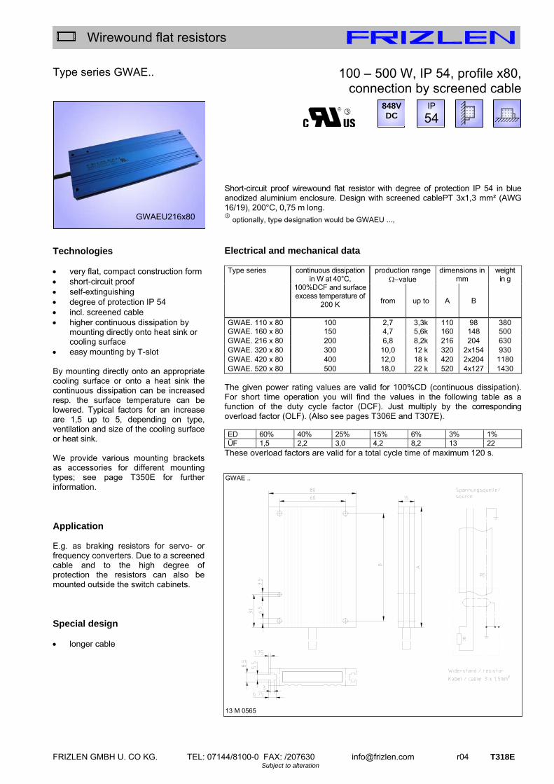
FRIZLEN GMBH U. CO KG. TEL: 07144/8100-0 FAX: /207630 [email protected] r04 T318E Subject to alteration
Wirewound flat resistors
Type series GWAE.. Technologies very flat, compact construction form short-circuit proof self-extinguishing degree of protection IP 54 incl. screened cable higher continuous dissipation by
mounting directly onto heat sink or cooling surface
easy mounting by T-slot By mounting directly onto an appropriate cooling surface or onto a heat sink the continuous dissipation can be increased resp. the surface temperature can be lowered. Typical factors for an increase are 1,5 up to 5, depending on type, ventilation and size of the cooling surface or heat sink. We provide various mounting brackets as accessories for different mounting types; see page T350E for further information. Application E.g. as braking resistors for servo- or frequency converters. Due to a screened cable and to the high degree of protection the resistors can also be mounted outside the switch cabinets. Special design longer cable
100 – 500 W, IP 54, profile x80, connection by screened cable
Short-circuit proof wirewound flat resistor with degree of protection IP 54 in blue anodized aluminium enclosure. Design with screened cablePT 3x1,3 mm² (AWG 16/19), 200°C, 0,75 m long.
optionally, type designation would be GWAEU ...,
Electrical and mechanical data
production range value
dimensions in mm
weight in g
Type series
continuous dissipation in W at 40°C,
100%DCF and surface excess temperature of
200 K from up to A B
GWAE. 110 x 80 100 2,7 3,3k 110 98 380GWAE. 160 x 80 150 4,7 5,6k 160 148 500 GWAE. 216 x 80 200 6,8 8,2k 216 204 630 GWAE. 320 x 80 300 10,0 12 k 320 2x154 930 GWAE. 420 x 80 400 12,0 18 k 420 2x204 1180 GWAE. 520 x 80 500 18,0 22 k 520 4x127 1430
The given power rating values are valid for 100%CD (continuous dissipation). For short time operation you will find the values in the following table as a function of the duty cycle factor (DCF). Just multiply by the corresponding overload factor (OLF). (Also see pages T306E and T307E). ED 60% 40% 25% 15% 6% 3% 1% ÜF 1,5 2,2 3,0 4,2 8,2 13 22
These overload factors are valid for a total cycle time of maximum 120 s.
GWAEU216x80
IP
54
GWAE ..
13 M 0565
848V DC

T319E r04 [email protected] FRIZLEN GMBH U. CO KG. TEL: 07144/8100-0 FAX: /207630 Subject to alteration
Wirewound flat resistors
Type series KWAD.. / KYAD.. Technologies extremely compact construction
form short-circuit proof self-extinguishing degree of protection up to IP 67 suited for rough environment easy mounting by T-slot Please note: The type series K.AD have no mounting holes. We provide various mounting brackets as accessories for different mounting types; see page T351E – T352 for further information. Option: Temperature switch (..Q) (only for type KW..Q.. – not for KY..)
This type series can be fitted with a 180°C temperature switch for monitoring which has 2 connection wires.
Type designation would be: KWADQ ... Application E.g. as brake resistor for frequency converters (fc). They are perfectly suited for rough environments because of their high degree of protection. With adequate mechanical protection of the wires, the resistors can be mounted outside the switch cabinets directly at the fc or motor. Special design E.g. with terminals, terminal box or
screened wiring or in multiple combination for higher dissipation values. See pages T320E and T341E.
150 – 1575 W, IP 54 or IP 67, profile x91
Short-circuit proof wirewound flat resistor in blue anodized aluminium enclosure. Design with 2 PTFE-wires, AWG 14/19 (1,9 mm²), 0,5 m long. Version with degree of protection IP 54 – type series KWAD.. (standard version) Version with degree of protection IP 67 – type series KYAD..
optionally, type designation would be K.ADU or. K.ADQU.., e.g. KWADQU 420x91 - 33
Electrical and mechanical data
continuous dissipation in W at 40°C, 100%DCF
and surface excess temperature of
production range
value
dimensions in mm
weight in kg
Type series KWAD – IP54 KYAD – IP67
200 Kticalpower
250 K from up to A
K. AD. 110 x 91 150 225 2,7 3,3k 110 0,7K. AD. 160 x 91 225 340 4,7 5,6k 160 1,0 K. AD. 216 x 91 300 450 6,8 8,2k 216 1,4 K. AD. 320 x 91 450 675 10,0 12 k 320 2,0 K. AD. 420 x 91 600 900 12,0 18 k 420 2,6 K. AD. 520 x 91 750 1125 18,0 22 k 520 3,2 K. AD. 620 x 91 900 1350 22,0 27 k 620 3,8 K. AD. 720 x 91 1050 1575 33,0 33 k 720 4,4
NOTE: excess temperature values of 200 K should not be exceeded in order not to risk the degree of protection!
The given power rating values are valid for 100%CD (continuous dissipation). For short time operation you will find the values in the following table as a function of the duty cycle factor (DCF). Just multiply by the corresponding overload factor (OLF). (Also see pages T306E and T307E). ED 60% 40% 25% 15% 6% 3% 1% ÜF 1,5 2,2 3,0 3,6 6,3 9,3 15
These overload factors are valid for a total cycle time of maximum 120 s.
KWAD / KYAD… (the figure shows the version with temperature switch (Q))
13 M 0558
KWAD 160 x 91
IP
54
IP
67
26.2
848VDC
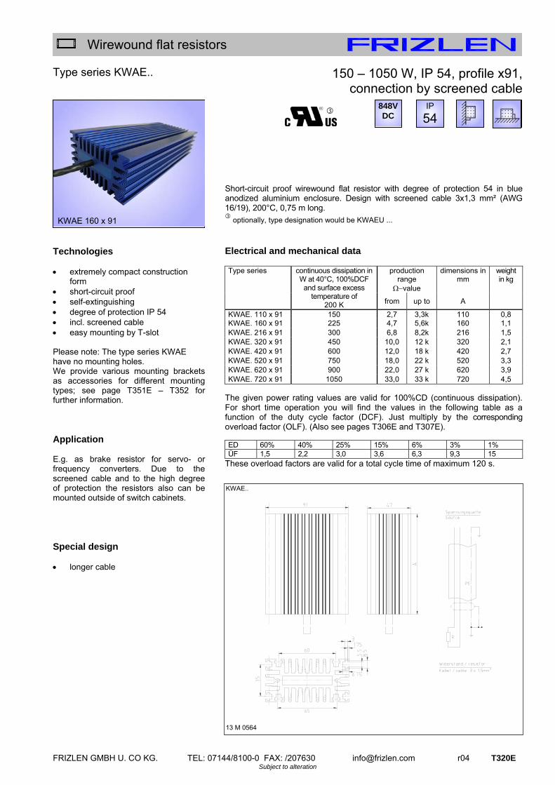
FRIZLEN GMBH U. CO KG. TEL: 07144/8100-0 FAX: /207630 [email protected] r04 T320E Subject to alteration
Wirewound flat resistors
Type series KWAE.. Technologies extremely compact construction
form short-circuit proof self-extinguishing degree of protection IP 54 incl. screened cable easy mounting by T-slot Please note: The type series KWAE have no mounting holes. We provide various mounting brackets as accessories for different mounting types; see page T351E – T352 for further information. Application E.g. as brake resistor for servo- or frequency converters. Due to the screened cable and to the high degree of protection the resistors also can be mounted outside of switch cabinets. Special design longer cable
150 – 1050 W, IP 54, profile x91, connection by screened cable
Short-circuit proof wirewound flat resistor with degree of protection 54 in blue anodized aluminium enclosure. Design with screened cable 3x1,3 mm² (AWG 16/19), 200°C, 0,75 m long.
optionally, type designation would be KWAEU ...
Electrical and mechanical data
production range
value
dimensions in mm
weight in kg
Type series
continuous dissipation in W at 40°C, 100%DCF
and surface excess temperature of
200 K from up to A
KWAE. 110 x 91 150 2,7 3,3k 110 0,8KWAE. 160 x 91 225 4,7 5,6k 160 1,1 KWAE. 216 x 91 300 6,8 8,2k 216 1,5 KWAE. 320 x 91 450 10,0 12 k 320 2,1 KWAE. 420 x 91 600 12,0 18 k 420 2,7 KWAE. 520 x 91 750 18,0 22 k 520 3,3 KWAE. 620 x 91 900 22,0 27 k 620 3,9 KWAE. 720 x 91 1050 33,0 33 k 720 4,5
The given power rating values are valid for 100%CD (continuous dissipation). For short time operation you will find the values in the following table as a function of the duty cycle factor (DCF). Just multiply by the corresponding overload factor (OLF). (Also see pages T306E and T307E). ED 60% 40% 25% 15% 6% 3% 1% ÜF 1,5 2,2 3,0 3,6 6,3 9,3 15
These overload factors are valid for a total cycle time of maximum 120 s.
IP
54
KWAE 160 x 91
KWAE..
13 M 0564
848V DC

T321E r04 [email protected] FRIZLEN GMBH U. CO KG. TEL: 07144/8100-0 FAX: /207630 Subject to alteration
Wirewound flat resistors
Type series GAMD, GBMD Technologies rated voltage max. 1100 VDC compact construction form in a
rectangular profile short-circuit proof self-extinguishing protection degree IP 54 usable in harsh environment higher continuous dissipation by
mounting directly onto heat sink or cooling surface
By mounting directly onto an appropriate cooling surface or onto a heat sink the continuous dissipation can be increased resp. the surface temperature can be lowered. , Typical factors for an increase are 1,5 up to 5, depending on type, ventilation and size of the cooling surface or heat sink. Option: temperature switch (..Q)
This type can be fitted with a 180° C temperature switch for monitoring, which has 2 connection wires.
Type designation would be: G.MDQ ... Application Different applications derive from the various dimensions in width, height and length. An important application is the use as braking resistor for motor/generator drive of motors with frequency converters. This type series is for frequency converters with higher voltage. With adequate mechanical protection the resistors can be mounted outside the switch cabinets directly at the fc or motor.
110 – 500 W, IP 54, profile x60 and x30
Short-circuit proof wirewound flat resistor, degree of protection IP 54 in blue anodized aluminium enclosure. Design with 2 FEP-wires, AWG 14/19 (2,1 mm²), 1000 V, 0,5 m long.
There are 2 versions available: horizontal – type series GAMD vertical – type series GBMD
optionally, type designation would be G.MDU.., e.g. GAMDU 215x60 - 180
Electrical and mechanical data
continuous dissipation in W at 40°C, 100% DCF and surface
excess temperature
of
production range
value
dimensions in mm weight in g
Type series
200 K Typi-cal
power
250 K
from up to A B C D G H J
GAMD. 165x60 110 165 2,2 6,8k 165 60 60 30 3 146 5,3 590GAMD. 215x60 155 235 3,3 10k 215 60 60 30 3 196 5,3 770 GAMD. 265x60 200 300 4,7 15k 265 60 60 30 3 246 5,3 950 GAMD. 335x60 270 400 6,8 22k 335 60 60 30 3 316 5,3 1200 GAMD. 405x60 330 500 8,2 27k 405 60 60 30 3 386 5,3 1450 GBMD. 165x30 110 165 2,2 6,8k 165 73 30 60 3 146 5,3 590 GBMD. 215x30 155 235 3,3 10k 215 73 30 60 3 196 5,3 770 GBMD. 265x30 200 300 4,7 15k 265 73 30 60 3 246 5,3 950 GBMD. 335x30 270 400 6,8 22k 335 73 30 60 3 316 5,3 1200 GBMD. 405x30 330 500 8,2 27k 405 73 30 60 3 386 5,3 1450
Note: Excess temperature values of 200 K should not be exceeded in order not to risk the degree of protection!
The given power rating values are valid for 100%CD (continuous dissipation). For short time operation you will find the values in the following table as a function of the duty cycle factor (DCF). Just multiply by the corresponding overload factor (OLF). (Also see pages T306E and T307E). ED 60% 40% 25% 15% 6% 3% 1% ÜF 1,5 2,2 3,0 4,2 8,2 13 22
These overload factors are valid for a total cycle time of maximum 120 s.
GAMD, GBMD… (the figure shows the version with temperature switch (Q))
13 M-0759-00-000
GBMD 405 x 30
GA.. GB..
IP
54 1100V
DC

FRIZLEN GMBH U. CO KG. TEL: 07144/8100-0 FAX: /207630 [email protected] r04 T322E Subject to alteration
Wirewound flat resistors
Type series GWMD / GYMD
Technologies rated voltage max. 1100 VDC very flat, compact construction form short-circuit proof self-extinguishing degree of protection IP 54 usable in harsh environment higher continuous dissipation by
mounting directly onto heat sink or cooling surface
easy mounting by T-slot By mounting directly onto an appropriate cooling surface or onto a heat sink the continuous dissipation can be increased resp. the surface temperature can be lowered. Typical factors for an increase are 1,5 up to 5, depending on type, ventilation and size of the cooling surface or heat sink. We provide various mounting brackets as accessories for different mounting types; see page T350E for further information. Option: Temperature switch (..Q) (only for type GWMDQ.. – not for GYMD)
This type can be fitted with a 180° C temperature switch for monitoring, which has 2 connection wires. Type designation would be: GWMDQ ... Application E.g. as brake resistor for frequency converters (fc). They are perfectly suited for rough environments because of their high degree of protection. With adequate mechanical protection of the wires the resistors can be mounted outside the switch cabinets directly at the fc or motor.
100 – 750 W, IP 54 or IP 67, profile x80 and x120
Short-circuit proof wirewound flat resistor, design with 2 FEP-wires, AWG 14/19 (2,1 mm²), 1000 V, 0,5 m long. Version with degree of protection IP 54 – type GWMD… (standard version) Version with degree of protection IP 67 – type GYMD…
optionally, type designation would be G.MDU or GWMDQU.., e.g. GWMDQU 420x80 - 33 Electrical and mechanical data
continuous dissipation in W at 40°C, 100% DCF and surface
excess temperature of
production range
value
dimensions in mm weight in g
Type series GWMD – IP54 GYMD – IP67
200 K Typicalpower
250 K from up to A B C D E F
G.MD. 110x80 100 150 2,7 3,3k 110 98 60 80 26,2 15 300G.MD. 160x80 150 225 4,7 5,6k 160 148 60 80 26,2 15 420 G.MD. 216x80 200 300 6,8 8,2k 216 204 60 80 26,2 15 550 G.MD. 320x80 300 450 10,0 12k 320 2x154 60 80 26,2 15 850 G.MD. 420x80 400 600 12,0 18k 420 2x204 60 80 26,2 15 1100G.MD. 520x80 500 750 18,0 22k 520 4x127 60 80 26,2 15 1350G.MD. 216x120 300 450 10,0 12k 216 204 100 120 35,8 20 1100
Note: Excess temperature values of 200 K should not be exceeded in order not to risk the degree of protection!
The given power rating values are valid for 100%CD (continuous dissipation). For short time operation you will find the values in the following table as a function of the duty cycle factor (DCF). Just multiply by the corresponding overload factor (OLF). (Also see pages T306E and T307E). ED 60% 40% 25% 15% 6% 3% 1% ÜF 1,5 2,2 3,0 4,2 8,2 13 22
These overload factors are valid for a total cycle time of maximum 120 s.
GWMD. / GYMD… (the figure shows the version with temperature switch (Q))
13 M 0358/13 M-0358-01-000
GWMD 110 x 80
IP
54
IP
67 1100V
DC
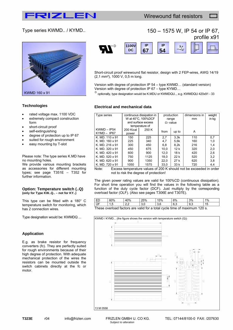
T323E r04 [email protected] FRIZLEN GMBH U. CO KG. TEL: 07144/8100-0 FAX: /207630 Subject to alteration
Wirewound flat resistors
Type series KWMD.. / KYMD.. Technologies rated voltage max. 1100 VDC extremely compact construction
form short-circuit proof self-extinguishing degree of protection up to IP 67 suited for rough environment easy mounting by T-slot Please note: The type series K.MD have no mounting holes. We provide various mounting brackets as accessories for different mounting types; see page T351E – T352 for further information. Option: Temperature switch (..Q) (only for Type KW..Q.. – not for KY..) This type can be fitted with a 180° C temperature switch for monitoring, which has 2 connection wires. Type designation would be: KWMDQ ... Application E.g. as brake resistor for frequency converters (fc). They are perfectly suited for rough environments because of their high degree of protection. With adequate mechanical protection of the wires the resistors can be mounted outside the switch cabinets directly at the fc or motor.
150 – 1575 W, IP 54 or IP 67, profile x91
Short-circuit proof wirewound flat resistor, design with 2 FEP-wires, AWG 14/19 (2,1 mm²), 1000 V, 0,5 m long. Version with degree of protection IP 54 – type KWMD… (standard version) Version with degree of protection IP 67 – type KYMD…
optionally, type designation would be K.MDU or KWMDQU.., e.g. KWMDQU 420x91 - 33
Electrical and mechanical data
continuous dissipation in W at 40°C, 100%DCF
and surface excess temperature of
production range
value
dimensions in mm
weight in kg
Type series KWMD – IP54 KYMD – IP67
200 Kical power
250 K from up to A
K. MD. 110 x 91 150 225 2,7 3,3k 110 0,7K. MD. 160 x 91 225 340 4,7 5,6k 160 1,0 K. MD. 216 x 91 300 450 6,8 8,2k 216 1,4 K. MD. 320 x 91 450 675 10,0 12 k 320 2,0 K. MD. 420 x 91 600 900 12,0 18 k 420 2,6 K. MD. 520 x 91 750 1125 18,0 22 k 520 3,2 K. MD. 620 x 91 900 1350 22,0 27 k 620 3,8 K. MD. 720 x 91 1050 1575 33,0 33 k 720 4,4
Note: Excess temperature values of 200 K should not be exceeded in order not to risk the degree of protection!
The given power rating values are valid for 100%CD (continuous dissipation). For short time operation you will find the values in the following table as a function of the duty cycle factor (DCF). Just multiply by the corresponding overload factor (OLF). (Also see pages T306E and T307E). ED 60% 40% 25% 15% 6% 3% 1% ÜF 1,5 2,2 3,0 3,6 6,3 9,3 15
These overload factors are valid for a total cycle time of maximum 120 s.
KWMD / KYMD... (the figure shows the version with temperature switch (Q))
13 M 0558
KWMD 160 x 91
IP
54
IP
67
26.2
1100VDC
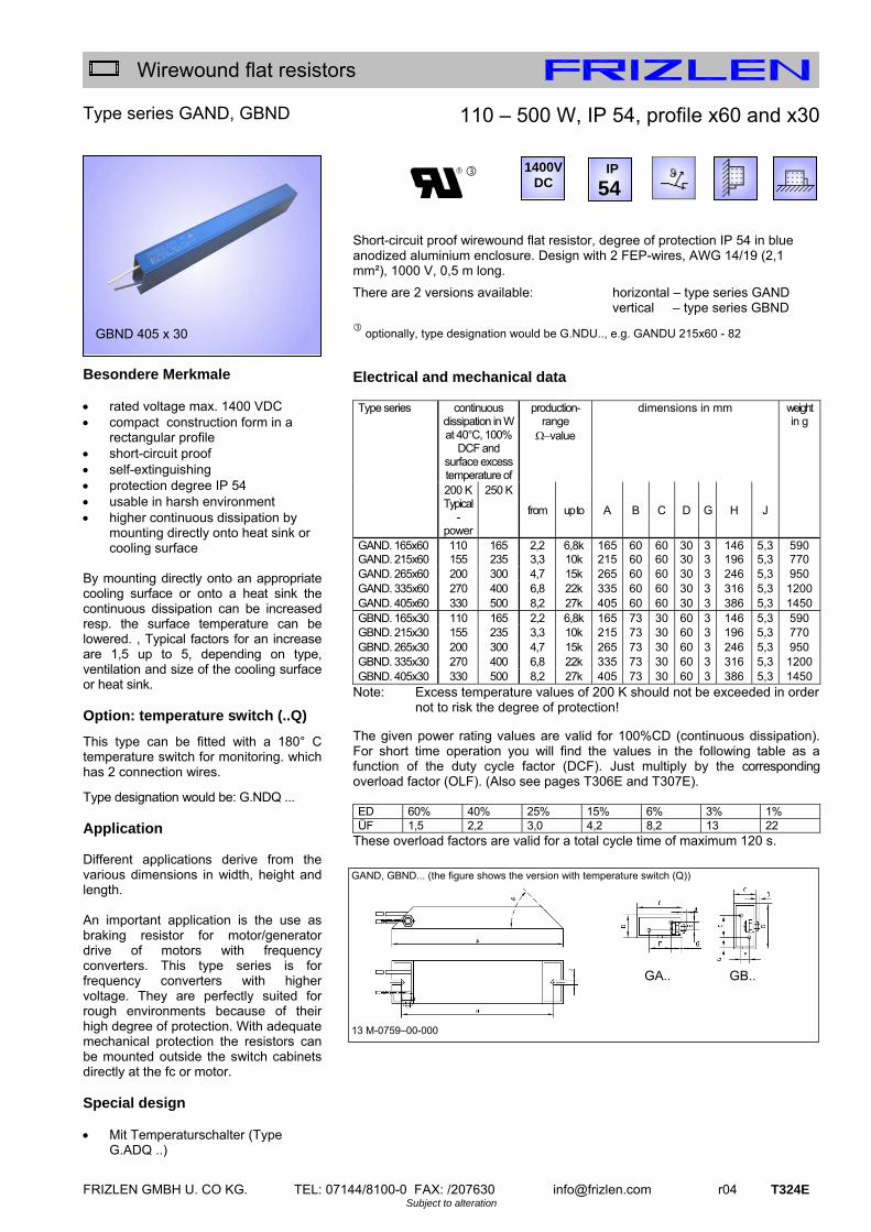
FRIZLEN GMBH U. CO KG. TEL: 07144/8100-0 FAX: /207630 [email protected] r04 T324E Subject to alteration
Wirewound flat resistors
Type series GAND, GBND Besondere Merkmale rated voltage max. 1400 VDC compact construction form in a
rectangular profile short-circuit proof self-extinguishing protection degree IP 54 usable in harsh environment higher continuous dissipation by
mounting directly onto heat sink or cooling surface
By mounting directly onto an appropriate cooling surface or onto a heat sink the continuous dissipation can be increased resp. the surface temperature can be lowered. , Typical factors for an increase are 1,5 up to 5, depending on type, ventilation and size of the cooling surface or heat sink. Option: temperature switch (..Q)
This type can be fitted with a 180° C temperature switch for monitoring. which has 2 connection wires.
Type designation would be: G.NDQ ... Application Different applications derive from the various dimensions in width, height and length. An important application is the use as braking resistor for motor/generator drive of motors with frequency converters. This type series is for frequency converters with higher voltage. They are perfectly suited for rough environments because of their high degree of protection. With adequate mechanical protection the resistors can be mounted outside the switch cabinets directly at the fc or motor. Special design Mit Temperaturschalter (Type
G.ADQ ..)
110 – 500 W, IP 54, profile x60 and x30
Short-circuit proof wirewound flat resistor, degree of protection IP 54 in blue anodized aluminium enclosure. Design with 2 FEP-wires, AWG 14/19 (2,1 mm²), 1000 V, 0,5 m long.
There are 2 versions available: horizontal – type series GAND vertical – type series GBND
optionally, type designation would be G.NDU.., e.g. GANDU 215x60 - 82
Electrical and mechanical data
continuous dissipation in W at 40°C, 100%
DCF and surface excess temperature of
production- range value
dimensions in mm weight in g
Type series
200 K Typical
- power
250 K
from up to A B C D G H J
GAND. 165x60 110 165 2,2 6,8k 165 60 60 30 3 146 5,3 590GAND. 215x60 155 235 3,3 10k 215 60 60 30 3 196 5,3 770 GAND. 265x60 200 300 4,7 15k 265 60 60 30 3 246 5,3 950 GAND. 335x60 270 400 6,8 22k 335 60 60 30 3 316 5,3 1200 GAND. 405x60 330 500 8,2 27k 405 60 60 30 3 386 5,3 1450 GBND. 165x30 110 165 2,2 6,8k 165 73 30 60 3 146 5,3 590 GBND. 215x30 155 235 3,3 10k 215 73 30 60 3 196 5,3 770 GBND. 265x30 200 300 4,7 15k 265 73 30 60 3 246 5,3 950 GBND. 335x30 270 400 6,8 22k 335 73 30 60 3 316 5,3 1200 GBND. 405x30 330 500 8,2 27k 405 73 30 60 3 386 5,3 1450
Note: Excess temperature values of 200 K should not be exceeded in order not to risk the degree of protection!
The given power rating values are valid for 100%CD (continuous dissipation). For short time operation you will find the values in the following table as a function of the duty cycle factor (DCF). Just multiply by the corresponding overload factor (OLF). (Also see pages T306E and T307E). ED 60% 40% 25% 15% 6% 3% 1% ÜF 1,5 2,2 3,0 4,2 8,2 13 22
These overload factors are valid for a total cycle time of maximum 120 s.
GAND, GBND... (the figure shows the version with temperature switch (Q))
13 M-0759–00-000
IP
54
GBND 405 x 30
1400VDC
GA.. GB..

T325E r04 [email protected] FRIZLEN GMBH U. CO KG. TEL: 07144/8100-0 FAX: /207630 Subject to alteration
Wirewound flat resistors
Type series GAPD, GBPD Technologies rated voltage max. 4200 VDC compact construction form in a
rectangular profile short-circuit proof self-extinguishing protection degree IP 54 usable in harsh environment higher continuous dissipation by
mounting directly onto heat sink or cooling surface
By mounting directly onto an appropriate cooling surface or onto a heat sink the continuous dissipation can be increased resp. the surface temperature can be lowered. , Typical factors for an increase are 1,5 up to 3, depending on type, ventilation and size of the cooling surface or heat sink. Application An important application is the use as resistor for charging- and discharging for higher voltage. They are perfectly suited for rough environments because of their high degree of protection. With adequate mechanical protection the resistors can be mounted outside the switch cabinets.
200 - 300 W, IP 54, profile x60 and x30
Short-circuit proof wirewound flat resistor, degree of protection IP 54 in blue anodized aluminium enclosure. Design with 0,5 m length of silicone isolated neon cable FZLSi 1,0 mm².
There are 2 versions available: horizontal – type series GAPD vertical – type series GBPD
Electrical and mechanical data
continuous dissipation in W at 40°C, 100%
DCF and surface excess temperature of
production-range value
dimensions in mm weight in g
Type series
200 K typical-power
250 K from up to A B C D E F H
GAPD 405x60 200 300 3,9 10k 405 60 60 30 0 13,5 386 1450GBPD 405x30 200 300 3,9 10k 405 73 30 60 13,5 0 386 1450
Note: Excess temperature values of 200 K should not be exceeded in order not to risk the degree of protection!
The given power rating values are valid for 100%CD (continuous dissipation). For short time operation you will find the values in the following table as a function of the duty cycle factor (DCF). Just multiply by the corresponding overload factor (OLF). (Also see pages T306E and T307E). ED 60% 40% 25% 15% 6% 3% 1% ÜF 1,5 2,2 3,0 4,2 8,2 13 22
These overload factors are valid for a total cycle time of maximum 120 s.
13 M-0651-00-002
GAPD 405 x 60
IP
54 4200V
DC
G=3
J=5,3
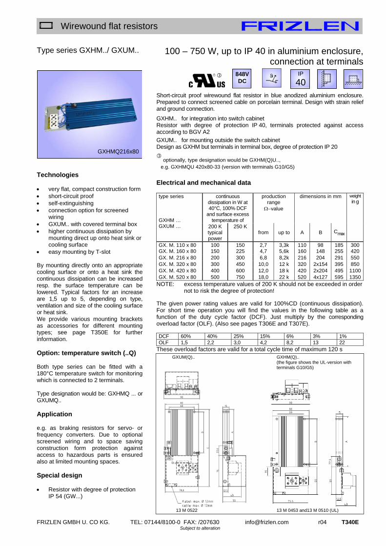
FRIZLEN GMBH U. CO KG. TEL: 07144/8100-0 FAX: /207630 [email protected] r04 T340E Subject to alteration
Wirewound flat resistors
Type series GXHM../ GXUM.. Technologies very flat, compact construction form short-circuit proof self-extinguishing connection option for screened
wiring GXUM.. with covered terminal box higher continuous dissipation by
mounting direct up onto heat sink or cooling surface
easy mounting by T-slot By mounting directly onto an appropriate cooling surface or onto a heat sink the continuous dissipation can be increased resp. the surface temperature can be lowered. Typical factors for an increase are 1,5 up to 5, depending on type, ventilation and size of the cooling surface or heat sink. We provide various mounting brackets as accessories for different mounting types; see page T350E for further information. Option: temperature switch (..Q) Both type series can be fitted with a 180°C temperature switch for monitoring which is connected to 2 terminals. Type designation would be: GXHMQ ... or GXUMQ.. Application e.g. as braking resistors for servo- or frequency converters. Due to optional screened wiring and to space saving construction form protection against access to hazardous parts is ensured also at limited mounting spaces. Special design Resistor with degree of protection
IP 54 (GW...)
100 – 750 W, up to IP 40 in aluminium enclosure, connection at terminals
Short-circuit proof wirewound flat resistor in blue anodized aluminium enclosure. Prepared to connect screened cable on porcelain terminal. Design with strain relief and ground connection.
GXHM.. for integration into switch cabinet Resistor with degree of protection IP 40, terminals protected against access according to BGV A2
GXUM.. for mounting outside the switch cabinet Design as GXHM but terminals in terminal box, degree of protection IP 20
optionally, type designation would be GXHM(Q)U..,
e.g. GXHMQU 420x80-33 (version with terminals G10/G5)
Electrical and mechanical data
continuous dissipation in W at 40°C, 100% DCF
and surface excess temperature of
production range
value
dimensions in mm weight in g
type series GXHM … GXUM … 200 K
typical power
250 K from up to A B Cmax
GX. M. 110 x 80 100 150 2,7 3,3k 110 98 185 300GX. M. 160 x 80 150 225 4,7 5,6k 160 148 255 420 GX. M. 216 x 80 200 300 6,8 8,2k 216 204 291 550 GX. M. 320 x 80 300 450 10,0 12 k 320 2x154 395 850 GX. M. 420 x 80 400 600 12,0 18 k 420 2x204 495 1100GX. M. 520 x 80 500 750 18,0 22 k 520 4x127 595 1350
NOTE: excess temperature values of 200 K should not be exceeded in order not to risk the degree of protection!
The given power rating values are valid for 100%CD (continuous dissipation). For short time operation you will find the values in the following table as a function of the duty cycle factor (DCF). Just multiply by the corresponding overload factor (OLF). (Also see pages T306E and T307E). DCF 60% 40% 25% 15% 6% 3% 1% OLF 1,5 2,2 3,0 4,2 8,2 13 22
These overload factors are valid for a total cycle time of maximum 120 s
GXHMQ216x80
IP
40 848V
DC
GXUM(Q).. GXHM(Q).. (the figure shows the UL-version with terminals G10/G5)
13 M 0522 13 M 0453 and13 M 0510 (UL)

T341E r04 [email protected] FRIZLEN GMBH U. CO KG. TEL: 07144/8100-0 FAX: /207630 Subject to alteration
Wirewound flat resistors
Type series FDWZ.. / FYWZ.. Technologies compact construction form short-circuit proof self-extinguishing degree of protection IP 54 or IP 65 incl. terminals in terminal box All connections are wired to G10 terminals in the mounted terminal box. A M25 cable gland can be used for cable inlet and strain relief. Option: Temperature switch (..Q) (only for type series FDWZ.. – not for FYWZ..) This type series can be fitted with a 180°C temperature switch for monitoring, which is wired on two terminals in the terminal box. Type designation would be: FDWZQ... Application E.g. as brake resistor for servo- or frequency converters. Due to the terminals in the terminal box various connection conditions and a high degree of protection can be realized at the same time. Thus the resistors also can be mounted outside of switch cabinets at various environment conditions. Special design optionally with connection cable,
screened or unscreened optionally for 1100V DC
225 – 2520 W, IP 54 or IP65, in aluminium enclosure, with terminals and terminal box
Short-circuit proof wirewound flat resistor in single, double or triple configuration. Degree of protection IP 54 or IP 65 in blue anodized aluminium enclosure. Design with terminals and strain relief by cable inlet in terminal box. Version with protection degree IP 54 – type FDWZ.. (standard version) Version with protection degree IP 65 – type FYWZ.. Electrical and mechanical data
production range
value
dimensions in mm weight in kg
Type series
continuous dissipation in W at 40°C, 100%DCF and surface
excess temperature of
200 K
from tp to A B C D E F
F.WZ.51201.. 225 4,7 5,6k 245 100 34 90 110 90 1,9 F.WZ.51301.. 300 6,8 8,2k 301 100 34 146 110 90 2,3 F.WZ.51401.. 450 10,0 12 k 405 100 34 250 110 90 2,9 F.WZ.51501.. 600 12,0 18 k 505 100 74 270 110 90 3,5 F.WZ.51601.. 750 18,0 22 k 605 100 74 370 110 90 4,1 F.WZ.51701.. 900 22,0 27 k 705 100 74 470 110 90 4,8 F.WZ.51801.. 1050 33,0 33 k 805 100 74 570 110 90 5,4 F.WZ.51202.. 360 4,7 5,6k 245 160 34 90 190 170 3,3 F.WZ.51302.. 480 6,8 8,2k 301 160 34 146 190 170 4,0 F.WZ.51402.. 720 10,0 12 k 405 160 34 250 190 170 5,2 F.WZ.51502.. 960 12,0 18 k 505 160 74 270 190 170 6,5 F.WZ.51602.. 1200 18,0 22 k 605 160 74 370 190 170 7,7 F.WZ.51702.. 1440 22,0 27 k 705 160 74 470 190 170 9,0 F.WZ.51802.. 1680 33,0 33 k 805 160 74 570 190 170 10,2 F.WZ.51203.. 540 4,7 5,6k 245 200 34 90 270 250 4,7 F.WZ.51303.. 720 6,8 8,2k 301 200 34 146 270 250 5,7 F.WZ.51403.. 1080 10,0 12 k 405 200 34 250 270 250 7,7 F.WZ.51503.. 1440 12,0 18 k 505 200 74 270 270 250 9,6 F.WZ.51603.. 1800 18,0 22 k 605 200 74 370 270 250 11,4 F.WZ.51703.. 2160 22,0 27 k 705 200 74 470 270 250 13,3 F.WZ.51803.. 2520 33,0 33 k 805 200 74 570 270 250 15,2
IP
65
FDWZ 5170302
IP
54 848VDC
F.WZ...
13 M 0569

FRIZLEN GMBH U. CO KG. TEL: 07144/8100-0 FAX: /207630 [email protected] r04 T342E Subject to alteration
Wirewound flat resistors
Type series FDAZ.. / FYAZ..
Technologies compact construction form short-circuit proof self-extinguishing degree of protection IP 54 or IP 65 incl. terminals in terminal box All connections run on ST terminals in the mounted terminal box. Cable gland M25 (up to 2,4 kW cont.diss.) or M32 can be used for cable inlet and strain relief. Option: Temperature switch (..Q) (only for type series FDAZ.. – not for FYAZ..) This type series can be fitted with a 180°C temperature switch for monitoring (incl. M12 or M20 cable gland), which is wired on two terminals in the terminal box. Type designation would be: FDAZQ... Application E.g. as brake resistor for servo- or frequency converters. Due to the terminals in the terminal box various connection conditions and a high degree of protection can be realized at the same time. Thus the resistors also can be mounted outside of switch cabinets at various environment conditions. Special design optionally with connection cable,
screened or unscreened optionally up to 1100V DC
160 – 4800 W, IP 54 or IP65, in aluminium enclosure, with terminals and terminal box
Short-circuit proof wirewound flat resistor in multiple configuration. Degree of protection IP 54 or IP 65 in blue anodized aluminium enclosure. Design with terminals and strain relief provision in terminal box. Version with protection degree IP 54 – type FDAZ.. (standard version) Version with protection degree IP 65 – type FYAZ..
Electrical and mechanical data
production range
value
dimensions in mm weight in kg
Type series FDAZ – IP54 FYAZ – IP65
continuous dissipation in W at 40°C, 100%DCF and surface
excess temperature of
200 K
from up to L H M O R U
F.AZ.52102.. 160 1,5 8,2 k 211 120 226 290 92 64 2,3 F.AZ.52202.. 240 2,7 5,6 k 261 120 276 340 92 64 2,6 F.AZ.52302.. 320 3,9 3,9 k 311 120 326 390 92 64 2,9 F.AZ.52502.. 640 6,8 2,2 k 511 120 526 590 92 64 3,8 F.AZ.52602.. 800 10,0 1,8 k 611 120 626 690 92 64 4,5 F.AZ.52204.. 480 1,2 2,7 k 261 120 276 340 185 150 3,6 F.AZ.52304.. 640 1,8 2,2 k 311 120 326 390 185 150 4,2 F.AZ.52504.. 1280 3,3 1,0 k 511 120 526 590 185 150 6,7 F.AZ.52604.. 1600 4,7 820 611 120 626 690 185 150 7,9 F.AZ.52506.. 1920 2,2 680 511 120 526 610 275 240 9,2 F.AZ.52606.. 2400 3,3 560 611 120 626 710 275 240 10,9 F.AZ.52508.. 2560 1,5 560 511 210 526 610 185 150 11,6 F.AZ.52608.. 3200 2,2 390 611 210 626 710 185 150 13,9 F.AZ.52512.. 3840 1,2 330 511 210 526 610 266 240 16,2 F.AZ.52612.. 4800 1,5 270 611 210 626 710 266 240 19,5
IP
65
F.AZ...
13 M0420
IP
54 848VDC
FDAZ 5661202
K=6,5x12
F.AZ.52.02.. F.AZ.52.04..
F.AZ.52.08.. F.AZ.52.12..
F.AZ.52.06..

T343E r04 [email protected] FRIZLEN GMBH U. CO KG. TEL: 07144/8100-0 FAX: /207630 Subject to alteration
Wirewound flat resistors
Type series WPAZQ.. Technologies very compact design high degree of protection IP 54 very low excess of surface
temperature ( <40K) designed for water cooling by
industrial water and almost any standard cooling liquid (dirt particles 1mm)
max. working pressure 4 bar (test pressure 10 bar)
max. drop of pressure 0,5 bar with temperature switch Construction Power resistor: Electrical connection at terminals 16-95mm² (depending on design) in terminal box incl. cable gland up to M50. Cooling: The integrated Cu-tubes are for industrial water and almost any standard cooling liquids or oils – not for aggressive liquids, sea water or demineralized water. Water connection at 1 ¼ inch thread for max. 3600 litre/hour. Maximum “In-Water” +30°C, maximum “Out-Water“ +45°C. Application An important application is the use as internal load resistor or as brake resistor. The big advantage is the excellent transport of heat by the integrated cooling water connection. Special design Mounting and connection material
out of stainless steel with additional PT100 element integrated into switch cabinet
10 – 40 kW, IP 54, water cooled, with terminals and terminal box
Wire wound flat type resistors in protection degree IP 54 in aluminium enclosure, combined with water cooler with integrated Cu-tubes. Electric wiring on terminals in attached terminal box. Cooling connection on two pipe connections 1 ¼ inch (DIN ISO 228). Electrical and mechanical data
production range
value
dimensions in mm
approx. weight in kg
type series
continuous dissipation in
kW for cold “In-Water” of 20°C at 100%ED and a max. surface
excess temperature of
30 K
necessary flow of
cooling liquid in litre / h at a “Out-Water” temperature rise of 12K from up to A B
WPAZQ90404 10 900 4,5 2,7 k 220 200 25WPAZQ90604 15 1350 3,0 3,3 k 280 260 33 WPAZQ90804 20 1800 2,3 3,9 k 340 320 40 WPAZQ91004 25 2250 1,8 4,7 k 400 380 48 WPAZQ91204 30 2700 1,5 5,6 k 460 440 55 WPAZQ91404 35 3150 1,3 6,8 k 520 500 63 WPAZQ91604 40 3600 1,2 8,2 k 580 560 70
The given power rating values are valid for 100%CD (continuous dissipation). For short time operation you will find the values in the following table as a function of the duty cycle factor (DCF). Just multiply by the corresponding overload factor (OLF).
DCF 60% 40% 25% 15% 6% OLF 1,2 1,6 2,2 3,1 5,5
These overload factors are valid for a total cycle time of maximum 120 s
WPAZQ91404
IP
54 E 848V DC
WPAZQ..
13 M 0685

FRIZLEN GMBH U. CO KG. TEL: 07144/8100-0 FAX: /207630 [email protected] r04 T350E Subject to alteration
Wirewound flat resistors
Accessories for type series G..D..x 80 and ..x 120 Type MWS3..
Mounting brackets sets – 2 types
We provide 2 different kinds of brackets as accessories, they consist of 2 brackets incl. mounting material in loose addition. A version with a mounted temperature switch is shown below (optional). 1.) Mounting variation A: set of 2 brackets type MWS301L
(incl. Mounting material; 2 screws M4x6 and M4x20) A1: vertically mounted at the long side A2: hanging at the long side
A3: horizontally mounted on surface (side view) to A3:(plan view)
2.) Mounting variation B: set of 2 brackets type MWS302L (incl. Mounting material; 2 screws M4x6) B1: hanging at the short side B2: vertically mounted at the short side
Distance of holes L at G..D. 110x80.. L = 130 mm G..D. 320x80.. L = 340 mm G..D. 160x80.. L = 180 mm G..D. 420x80.. L = 440 mm G..D. 216x80.. L = 236 mm G..D. 520x80.. L = 540 mm G..D. 216x120.. L = 236 mm
Mounting plates- distance M = 23 mm
M = 27 mm
L
distance of holes B = 98 mm
M = 30 mm
Distance of holes L at G..D. 110x80.. L = 98 mm G..D. 320x80.. L = 308 mm G..D. 160x80.. L = 148 mm G..D. 420x80.. L = 408 mm G..D. 216x80.. L = 204 mm G..D. 520x80.. L = 508 mm G..D. 216x120.. L = 204 mm
L
L
Distance of holes L for G..D. 110x80.. to G..D. 216x80.. L = 98 mm G..D. 216x120.. L = 138 mm
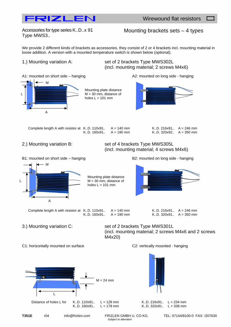
T351E r04 [email protected] FRIZLEN GMBH U. CO KG. TEL: 07144/8100-0 FAX: /207630 Subject to alteration
Wirewound flat resistors
Accessories for type series K..D..x 91 Type MWS3..
Mounting brackets sets – 4 types
We provide 2 different kinds of brackets as accessories, they consist of 2 or 4 brackets incl. mounting material in loose addition. A version with a mounted temperature switch is shown below (optional). 1.) Mounting variation A: set of 2 brackets Type MWS302L
(incl. mounting material; 2 screws M4x6) A1: mounted on short side – hanging A2: mounted on long side - hanging
2.) Mounting variation B: set of 4 brackets Type MWS305L (incl. mounting material; 4 screws M4x6) B1: mounted on short side – hanging B2: mounted on long side - hanging
3.) Mounting variation C: set of 2 brackets Type MWS301L
(incl. mounting material; 2 screws M4x6 and 2 screws M4x20)
C1: horizontally mounted on surface C2: vertically mounted - hanging
Complete length A with resistor at K..D. 110x91.. A = 140 mm K..D. 216x91.. A = 246 mm K..D. 160x91.. A = 190 mm K..D. 320x92.. A = 350 mm
Mounting plate distance M = 30 mm, distance of holes L = 101 mm
M = 24 mm
L
L
Complete length A with resistor at K..D. 110x91.. A = 140 mm K..D. 216x91.. A = 246 mm K..D. 160x91.. A = 190 mm K..D. 320x91.. A = 350 mm
M
A
Distance of holes L for K..D. 110x91.. L = 128 mm K..D. 216x91.. L = 234 mm K..D. 160x91.. L = 178 mm K..D. 320x91.. L = 338 mm
M
L Mounting plate distance M = 30 mm, distance of holes L = 101 mm
A

FRIZLEN GMBH U. CO KG. TEL: 07144/8100-0 FAX: /207630 [email protected] r04 T352E Subject to alteration
Wirewound flat resistors
4.) Mounting variation D: set of 4 brackets Type MWS306L (incl. mounting material; 4 screws M4x6 and 4 screws M4x20)
D1: horizontally mounted on surface D2: vertically mounted - hanging
More details about the distance of holes please look at our dimension sheet 13 M 0559.
M = 24 mm
Distance of holes L for K..D. 110x91.. L = 128 mm K..D. 420x91.. L = 438 mm K..D. 160x91.. L = 178 mm K..D. 520x91.. L = 538 mm K..D. 216x91.. L = 234 mm K..D. 620x91.. L = 638 mm K..D. 320x91.. L = 338 mm K..D. 720x91.. L = 738 mm
L

FRIZLEN GMBH U. CO KG. TEL: 07144/8100-0 FAX: /207630 [email protected] r04 T360E Subject to alteration
Wirewound flat resistors
Further type series as examples of customized solutions
1. Resistor wired on terminals, also in compact multiple design for high short time energy absorption
Type series FBEMS.. construction very
compact for horizontal
mounting connection at
terminals with ground
connection degree of
protection IP 20 (resistors IP 54)
Type series FBEM.. construction very
compact for vertical
mounting connection at
terminals with ground
connection degree of
protection IP 20 (resistors IP 54)
2. In multiple design for higher continuous dissipation
Type series GZDWM.. mica flat resistor
elements connection on
terminals with cover with ground
connection built-up with
elements which have UL Recognition
Type series FFAE.. flat type
construction mounting on
switch cabinet with grounded and
screened wiring degree of
protection IP 21 (resistors IP 54)
3. Special design for mounting beyond and beside servo- and frequency converter
Type series GUXD.. connection by wires for mounting beyond
and beside converters
scalable design degree of protection
IP 40
Type series GXWD.. connection by
wires for mounting
beyond and beside converters
optionally with ground and screen connection
degree of protection IP 54
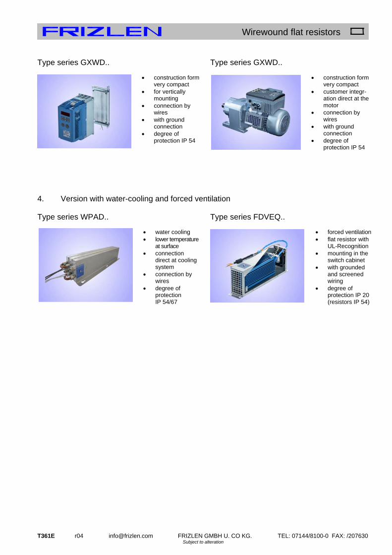
T361E r04 [email protected] FRIZLEN GMBH U. CO KG. TEL: 07144/8100-0 FAX: /207630 Subject to alteration
Wirewound flat resistors
Type series GXWD.. construction form
very compact for vertically
mounting connection by
wires with ground
connection degree of
protection IP 54
Type series GXWD.. construction form
very compact customer integr-
ation direct at the motor
connection by wires
with ground connection
degree of protection IP 54
4. Version with water-cooling and forced ventilation
Type series WPAD.. water cooling lower temperature
at surface connection
direct at cooling system
connection by wires
degree of protection IP 54/67
Type series FDVEQ.. forced ventilation flat resistor with
UL-Recognition mounting in the
switch cabinet with grounded
and screened wiring
degree of protection IP 20 (resistors IP 54)

www.fr iz len.com
t100
t200
t300
t400
t 4 0 0 – d i e b e L A s t b A r e N / t h e L o A d A b L e o N e s
Last- und Prüfwiderstände0,01 bis 250 Kilowatt
Stationäre oder mobile Stellwiderstandsgeräte für Labor oder Ver-
suchsfeld. Individuelle Auslegung je nach Leistung und Anforderungen
der Last in Stufen oder fein einstellbar.
Einsatzbereiche in Schulen und Universitäten, im Bereich Forschung
und Entwicklung. Für den Einsatz in der industriellen Nutzung in unter-
schiedlichen Schutzarten lieferbar.
Ein- und dreiphasige Ausführungen
Stufenlose bzw. stufi ge Einstellung des Widerstandswertes
Auch für mobilen Einsatz
Gehäuse verzinkt, lackiert bzw. aus Aluminium in Laborausführung
Load and test resistors0,01 up to 250 Kilowatt
Stationary or mobile loads for laboratory or test sites. Individually
designed according to the requirements of power and the type of
load, which can be fi ne adjustable or switched in steps.
For example at schools or universities, in research and development
or as well as in different degrees of protection for industrial needs.
One- or threephase design
Resistance value fi ne adjustable or switched in steps
For mobile use
Enclosure made from hot-galvanised sheet steel, varnished,
respectively out of aluminium in laboratory design

FRIZLEN GMBH U. CO KG. TEL: 07144/8100-0 FAX: /207630 [email protected] r04 T401E Subject to alteration
Load and test resistors
Contents
Properties
Applications
This list describes load and test resistors for laboratory environment, test rooms and industrial environment with different protection degrees. These resistor types are series resistor usable for different applications like voltage divider or as load resistor. The load and test resistors consist of different resistor elements out of our type series T100 to T600. maximum characteristics type series page power
survey T402E
technical details T403E
Laboratory resistors, fixed and adjustable
3,0 kW fixed resistors FZ.L T410E
1,4 kW slide resistors SZ.L T411E
3,8 kW slide resistors, with spindle drive SZ.PL T412E
0,25 kW potentiometers RGL T413E
1,0 kW slide resistors, with stop, stepped winding SU..L/SZ..L T414E
Laboratory resistors, switchable and adjustable
5,6 kW Adjustable, 14/28 V, laboratory version BW 18 – BW 81 T420E
50 kW Adjustable, 230/400 V, laboratory version BW 20 – BWV 83 T421E
Resistors in low weight design, switchable with steps
100 kW switchable with steps, mobile version BWMV37… T422E
Resistors in industrial version, fixed and switchable with steps
60 kW steelgrid resistors with natural cooling FA 3.. / FS 3.. T430E
250 kW steelgrid resistors with fan FAV 3.. / FSV 3.. T431E
250 kW steelgrid resistors with switch cabinet FAVR3../ FSVR3.. T432E
Further series T433E
low temperature coefficient for laboratory version and test area
constant ohmic value over a large temperature range
high powers adjustable
in steps by means of switches or contactors, or without steps by means of slider and spindle
one- and three-phase versions
Application for different power supplies, also for different voltages
enclosure made of hot galvanised steel sheet; type BWMV aluminium chassis
Laboratory version with additional varnishing
very robust construction
different protection degrees and installation possibilities, also mobile special varnishing
optionally and with additional charge, colour selection by availability control of the load steps
by electric contactors or switches placed in an attached switch cabinet for the type FAVR/FSVR or by internal switches for type BW and BWMV
regulating resistors in laboratory or test field, stationary or mobile
load resistors for batteries, battery chargers, UPS-units, generators, emergency power units
load resistors up to protection degree IP 23, usable for outdoor location
resistors for experimenting and testing in laboratories, schools and universities

T402E r04 FRIZLEN GMBH U. CO KG. TEL: 07144/8100-0 FAX: /207630 [email protected] Subject to alteration
Load and test resistors
symbol
T 400 - survey
type series characteristics
page
FZ.L
T410E
SZ.L
T411E
SZ.PL
T412E
RGL
T413E
SU.L -
SZ.L
T414E
BW18 -
BW81
T420E
BW18 -
BWV 83
T421E
BWMV 37..
T422E
FA./ FS. 3...
T430E
F.V 3…
T431E
F.VR.3...
T432E
typical power from [kW] 0,065 0,105 1,18 0,008 0,1 1,2 1,2 5 5 70 70
typical power up to [kW] 3 1,4 3,8 0,25 1,0 5,6 50 100 60 250 250
max. terminal connections 2 3 3 3 2 3 6 6 40 40 40
protection degree IP20 X X X X X X X X X X X
protection degree IP23 X X X
horizontal mounting X X X
temperature switch (optional)
X X X X
forced ventilation X X X X
transportable X
adjustable in steps X X X X
fine adjustment device X X X X X X
laboratory version X X X X X X X
IP
23
IP
20
Rights for improvements and modifications of our products reserved. Modifications, errors and misprints justify no claim for damages.
We refer to our terms of sales and delivery.

FRIZLEN GMBH U. CO KG. TEL: 07144/8100-0 FAX: /207630 [email protected] r04 T403E Subject to alteration
Load and test resistors
Technical details
Construction
Resistance values/ Production tolerance/
Temperature dependency
Air- and creepage distances
Protective measures
Terminal details
Permissible voltage
Starting up
This list includes resistors, which are derived from the type series T100 wirewound tubular fixed resistors, T200 cemented wirewound variable resistors, T500 lamina type fixed resistors and T600 steel-grid fixed resistors. More technical details are described in the lists of these resistor types. The resistance values in the column “production range“ refer to our standard production programm. The normal tolerance is 10%. The resistance value of the wirewound laboratory resistors is changing only slightly. The resistance will change between cold and warm condition: wiring made of CuNi 44 approx. ±1% and made of CrAl 25 5 approx. +1%. The resistance value for the resistors in industry version with steel-grid resistor elements, increases approx. +15% between cold and operating temperature. This is considered in the calculation for our load resistors, so that the rated power will be achieved at operating temperature. Air and creepage distances are rated according to IEC 664 (DIN EN 0110 part 1) for the overvoltage category III and degree of pollution 3 for grounded three-phase mains supplies up to 3 x 500 V. Testing voltage 2.5 kV AC. These data are valid for all devices that are connected to mains voltage and derived voltages, as for example the intermediate circuit voltage of frequency converters. Do not conclude from the calculated relation between the rated power and the maximum producible ohmic value to the rated voltage! All our power resistors with degree of protection IP 20 and IP 23, correspond to safety class I, i.e. connections for protective earth conductor according to EN 61140 are provided. These devices also comply with the CE low voltage directive. Power resistors being passive electronical or electrical units are not affected by the specific EMC standards. They do not produce any interfering radiations nor are they affected. The choice of the terminals and the wire cross-section is chosen according to the rated current. The electrical connections are made of with flexible, heat resistant, silicone-insulated wire. We use safety sockets or binding posts with flat clamp for the connections of our BW.. series load resistors. The maximum rated voltage is 500 V AC or DC for wirewound variable and slide resistors. Please be aware not to exceed the rated current of slide resistors. The maximum voltage is given on the name plate for load resistors. A higher voltage is not allowed, because the resistor will be overloaded and destroyed. You can check this with P=U²/R. Resistors in industry version. On first operation during commissioning, the steelgrid resistors will produce some smoke. This is due to the lubricant used in the manufacturing process of the resistor element.

T404E r04 FRIZLEN GMBH U. CO KG. TEL: 07144/8100-0 FAX: /207630 [email protected] Subject to alteration
Load and test resistors
Basic wirings and applications of adjustable
resistors
voltage divider
series resistor
Voltage divider wiring to adjust the voltage of an electrical load. Principally it is possible to realize a voltage divider wiring with an adjustable resistor, when the resistor has three terminals. Resistor begin 1 and resistor end 2 of the voltage divider resistor R1 are connected to the power supply UN. The consumer or test object R2 lies via connection 3 at the variable slider S. By adjusting the slider you can adjust the voltage of the electrical load between 0 and 100% UN. Is the electrical consumer or test object R2 self variable with changing current consumption, for example a DC - motor with different load, so it reduces principally the applied voltage at the slider S with increasing load current I2, the speed of the motor falls. Should this voltage decrease be held very low, the flowing current I1 through voltage divider resistor should be a multiple of the current I2 (I1 /I2= 5 up to 10), the same is valid for the power of the voltage divider resistor. By economic purpose you should take this application only for small electrical consumers up to 100W with UN=24V or up to 300W with UN=230V and should be limited for special cases. For this wiring you can take cemented wirewound variable resistors with enclosure of the type series RGL (page T413E) or cemented wirewound tubular fixed resistors of the type series SZL (page T411E) or SZ.PL (page T412E). Series resistor to adjust the current of an electrical load. Should the current of an electrical load or test object be adjusted with a constant voltage, you have to use the series resistor wiring. You need only the connection 1 (resistor begin) and connection 3 (slider). Resistor and electrical load are wired in series. The current of the series resistor and the electrical load is the same, the current is the highest in position 1, the lowest in position 2, if the series resistor is fully efficient. The series resistor wiring is used for example to adjust the field current of DC – motors and DC-current- or synchronous generators, the exciting current of magnetic- or eddy current brakes, the premagnetisation current of ripple filter chokes to adjust the ripple of current of an arc welder. To dimension a series resistor, the following data are needed, shown for example for a field rheostat of a small synchronous generator: Rated voltage UN (here 110V DC); rated resistor R2 of the electrical load (here cold resistor value of the exciter field 40 ohm) Maximum current of the load: Desired minimal current Imin (here Imin= 2A). This gives a current rate Imax/Imin (here: 2,75A/2A=1,375). Now you can calculate the necessary resistance value of the series resistor R1 corresponding to the wiring in series of the two resistors R1 and R2. Here:
The minimum power of the series resistor will be calculated according to: The series resistor can be realized, when it must be operationally adjusted, as a cement coated wirewound variable resistor with enclosure corresponding to our type RGL (page T413E) or as a cement coated wirewound slide resistor corresponding to our type SZL (page T411E) or SZ.PL (page T412E). You will have the following two solutions in this example: A cement coated wirewound variable resistor type RGL 250-15 with a typical power of 150 W or a cemented wirewound slide resistor as our type SZL 200x45 -15 with a typical power of 135 W.
3
S
2
R2
I2
1
UN
I1
R1
AV
R
UI N 75,2
40
110
.max.max
UN I2
I1 1
R1
2R2
3
S
154055402
1102
.min1 A
VR
I
UR N
WARIP 11315)²75,2(² 1max

FRIZLEN GMBH U. CO KG. TEL: 07144/8100-0 FAX: /207630 [email protected] r04 T405E Subject to alteration
Load and test resistors
load resistor
wiring example BW18 – BWV83
F – fine adjustment,
potentiometer or slide resistor G – rough adjustment, cam
switch
If the adjusting range of current between Imax and Imin should be higher than the factor 1,5, it can be favourable to use a stepped winding, which is adapted to the flow of the current. You will receive a reduced resistor size then. This can be realized either for wire wound variable resistors with a stepped winding made of a blank wire (then type RGL..A) or for slide resistors with a stepped winding made of an isolated-oxidized resistance wire (then type series SU.L..x..G or. SU.PL…x…G). We need for the calculation of the resistor size the above mentioned data. Remark: If it is not necessary for the application to adjust the current operationally and permanently, but only one time for the start-up procedure or occasionally for changes in the facility, it could be more economical to use a tubular fixed resistor of our list T100, which is adjustable with an adjustable clip instead of the operationally adjustable resistor, which are described here. Load resistor wiring to adjust the continuous dissipation. Adjustable resistors are mostly used as load resistors for one- or three phase supply units. In development, laboratories are tested power supply and charging units, rectifiers, inverters or Ups – units, in hospitals emergency power batteries or emergency power units must be checked continuously according to their function. So there are various requirements, for which you need different solutions. To make the selection easier for our customer, we offer in our lists resistors with our long-time experience, with which we can achieve most of the customer applications. You find typically load resistors up to 1 kW on page T414E. These are our slide-resistors built with 2 terminals and a linear or stepped winding. These resistors have 2 winding parts, the so-called fixed resistor part RF, which is responsible for the maximum power and which can not be reduced and the effective slide resistor part RS. For protection of the fixed resistor part we can deliver a mechanical stop. Concerning the load resistors of our type series BW 18 – BWV 83 on page T420E and T421E from 1,2 kW up to 50 kW there are connected multiple resistor steps in parallel to receive a higher continuous dissipation. If there is no solution for a special application with our listed resistors, we need (for the dimensioning of your special load resistor) the following detail:
- rated voltage UN, one- or three phase, DC or AC - maximum power Pmax respectively maximum current Imax - minimum power Pmin respectively minimum current Imin
Remark to the voltage and power rating : Operators often need loads for different rated voltages and currents, e.g. from 14 V DC up to 230 V AC or 3 x 400 V AC for currents from 1 A up to 10 A and they want normally to use one single load resistor. But this is not possible mostly because of technical and economical reasons.
F UN
G

T406E r04 FRIZLEN GMBH U. CO KG. TEL: 07144/8100-0 FAX: /207630 [email protected] Subject to alteration
Load and test resistors
The dimensioning of a load resistor is normally made for a rated voltage UN, which corresponds to the maximum voltage. Hereby the maximum continuous dissipation Pmax is calculated. Of course this load resistor can be used with smaller voltages Ux , but then you will receive a smaller continuous dissipation Px. E.g. for a load resistor with a rated voltage of 28 V DC, which is used with 24 V DC, then the continuous dissipation is reduced Px to 73%. To increase the economic efficiency and the customer`s benefit we have engineered two wiring solutions, which are permitted for 2 voltages while retaining the full continuous dissipation. On the one hand these are load resistors for 2 voltages, which are in relation 1:2. You will find different types on page T420E, for examples.
On the other hand we can build our threephase load resistors according to our page T421E with 6 terminals. Thereby you can use it with the complete continuous dissipation either for 3 x 400 V AC in star wiring or for 3 x 230 V AC in delta wiring or additional for 230 V AC in parallel wiring.
For star and delta wiring
Remark to the usage of a rheostat in slide- or cement coated wirewound variable version as load resistor, which does not protect the series resistor with a mechanical stop: Basically you can use each rheostat as load resistor. The operator must be careful, that the rated current, which is given also on the name plate, will not be exceeded and especially the resistor will not be short-circuited, because the load resistor will be destroyed then.
kWV
VP
U
UxPx
N2,1*)²
28
24(max*)²(

FRIZLEN GMBH U. CO KG. TEL: 07144/8100-0 FAX: /207630 [email protected] r04 T410E Subject to alteration
Load and test resistors
Type series FZL / FZZL / FZDL Technologies 2 safety sockets 4 mm 1 earthing safety socket 4mm completely closed enclosure rubber feet for location on tables The safety sockets form a secure 4 mm plug system together with the adjusted safety plugs, which are protected by rigid insulation coverings. So you cannot touch any blank energised parts. The use of conventional 4 mm plugs is possible; we do not provide a lug connection. Application These resistors are suitable for educational modelling and experimenting applications, for load testing in laboratories, schools and universities as well as for manufacturing. Engineering consultants and development divisions use these handy devices. Special design
individual varnish on request with micro-fuse
fixed resistors in laboratory design 65 – 3000 W
Cemented wirewound tubular fixed resistor in one-, two- or three-tube design, in laboratory version, enclosure with aluminium coloured varnish and rubber feet. Degree of protection IP 20. Electrical and mechanical data
production range
value
dimension in mm approx.weight
in kg
Type series L x D
typical power in
W at 40°C, 100% DCF
from to H O R
FZL 100x35 65 0,22 22k 82 137 66 0,5 FZL 200x35 150 0,56 47k 82 237 66 0,7 FZL 160x45 150 0,47 33k 92 206 75 0,7 FZL 200x45 180 0,68 39k 92 246 75 0,8 FZL 300x45 300 1,2 56k 92 346 75 1,1 FZL 300x65 430 6,8 47k 125 346 92 1,8 FZL 400x65 600 10 68k 125 446 92 2,3 FZZL 300x65 860 3,9 82k 125 346 185 3,6 FZZL 400x65 1200 5,6 120k 125 446 185 4,4 FZZL 500x65 1600 6,8 150k 125 546 185 5,4 FZZL 600x65 2000 8,2 180k 125 646 185 6,4 FZDL 500x65 2400 3,9 150k 125 546 275 7,8 FZDL 600x65 3000 5,6 180k 125 646 275 9,2
IP
20
FZL 200x35
FZL.. FZZL.. FZDL..
O
11 M 0700

T411E r04 FRIZLEN GMBH U. CO KG. TEL: 07144/8100-0 FAX: /207630 [email protected] Subject to alteration
Load and test resistors
Type series SZL / SUL Type series SZZL / SUZL Technologies 3 safety sockets 4 mm 1 earthing safety socket 4mm completely closed enclosure rubber feet for location on tables load capacity up to 15 A The safety sockets form a secure 4 mm plug system together with the adjusted safety plugs, which are protected by rigid insulation coverings. So you cannot touch any blank energised parts. The use of conventional 4 mm plugs is possible; we do not provide a lug connection. The resistance value can be adjusted between zero and the requested maximum resistance value by a slider. Attention: There is danger of burning, because the slider is possibly in the heat sector. We also equip with a spindle drive, which is charged additionally. (only D=65 + 85). The adjustment is accomplished sensitively by turning a handwheel. The adjustable slide resistor can be used as voltage divider with three sockets as well as series resistor with two sockets. When optionally equipped with micro-fuse only wiring as series resistor is possible (2 sockets). If you use an adjustable slide resistor as load resistor we suggest a stepped winding adapted to the flow of the current. Even more so if the adjusting range of current is higher than 1:1,5. The resistance wire will be oxidized and is therefore insulating. You will get a reduced resistor size. type SU.L .. x .. G (Compare technical indications for dimensioning on page T414E) Special design
individual varnish on request with micro-fuse
adjustable slide resistors 105 – 1400 W, up to max. 15 A
SZ.L .. Cemented one-tube(SZL..)- or two-tube (SZZL..) adjustable slide
resistors with manual operation (standard version) SU.L .. Uncemented one-tube (SUL..)- or two-tube (SUZL..)- adjustable slide
resistors with manual operation (special version) in laboratory version, enclosure with aluminium coloured varnish and rubber feet, degree of protection IP 20.
Elektrische und mechanische Daten
dimensions in mm Type series
typical power in W at a surface temperature of
production range
value
approx.weight
in kg
L x D 250°C 300°C von bis H
P nur
S..PL L O R
SZL 160x45 105 150 0,47 1,2 k 123 153 160 206 75 1,2SZL 200x45 135 180 0,56 1,8 k 123 153 200 246 75 1,5 SZL 300x45 210 285 1,0 2,7 k 123 153 300 346 75 1,8 SZ.L 300x65 320 430 1,5 3,9 k 156 186 300 346 92 2,5 SZ.L 400x65 440 600 1,8 5,6 k 156 186 400 446 92 3,2 SZ.L 400x85 610 850 2,7 6,8 k 181 211 400 450 120 4,2 SZZ.L 300x65 620 860 2,7 1,8 k 156 186 300 346 185 4,5 SZZ.L 400x65 870 1200 3,9 2,7 k 156 186 400 446 185 5,5 SZZ.L 500x65 1120 1600 5,6 3,3 k 156 186 500 546 185 6,5 SZZ.L 600x65 1400 2000 6,8 4,7 k 156 186 600 646 185 7,5
At continuous dissipation we advise to select from the table surface temperature 250°C.
SZ.L / SU.L .. with manual operation SZL / SUL SZZL / SUZL
11 M 0200
SZ.PL / SU.PL .. with spindle drive SZPL / SUPL SZZPL / SUZPL
11 M 0201
IP
20
SZL 400x65

FRIZLEN GMBH U. CO KG. TEL: 07144/8100-0 FAX: /207630 [email protected] r04 T412E Subject to alteration
load and test resistors
Type series SZZPL / SUZPL Type series SZDPL / SUDPL Technologies with spindle drive 3 safety sockets 4 mm 1 earthing safety socket 4mm completely closed enclosure rubber feet for location on tables load capacity up to 30 A
(one-phase version) The safety sockets form a secure 4 mm plug system together with the adjusted safety plugs, which are protected by rigid insulation coverings. So you cannot touch any blank energised parts. The use of conventional 4 mm plugs is possible; we do not provide a lug connection. The resistance value can be adjusted between zero and the requested maximum resistance value. The adjustment is accomplished sensitively by turning a handwheel. The advantage of the spindle drive is, that there is no danger of burning, because the operating is outside the heat sector. The adjustable slide resistor can be used as voltage divider with three sockets as well as series resistor with two sockets. When optionally equipped with micro-fuse only wirings of series resistor is possible (2 sockets). If you use an adjustable slide resistor as load resistor we suggest a stepped wiring adapted to the flow of the current. Even more so if the adjusting range of current is higher than 1:1,5. The resistance wire will be oxidized and is therefore insulating. You will get a reduced resistor size Type SU.PL .. x .. G, see page 414E
Special design
individual varnish on request with micro-fuse three-phase version
(only type series S.DPL)
adjustable slide resistors 1180 – 3800 W, up to max. 30 A
SZ.PL .. Cemented two-tube (SZZPL..)- or three-tube (SZDPL..) adjustable
slide resistors with spindle drive (standard version) SU.PL .. Uncemented two-tube (SUZPL..)- or three-tube (SUDPL..) adjustable
slide resistors with spindle drive (special version) in laboratory version, enclosure with aluminium coloured varnish and rubber feet, degree of protection IP 20. Electrical and mechanical data Type series typical power in W
at a surface temperature of
production range
value
dimensions in mm weight in kg
L x D 250°C 300°C von bis H L O R
SZZPL 400x85 1180 1700 1,2 3,3k 235 400 444 230 8,5SZZPL 600x85 1880 2700 1,8 4,7k 235 600 644 230 11,5 SZZPL 800x85 2520 3700 2,7 6,8k 235 800 844 230 14,5 SZDPL 600x85 2800 4000 2,7 3,3k 235 600 644 340 15,0 SZDPL 800x85 3800 5500 3,9 4,7k 235 800 844 340 23,0
At continuous dissipation we advise to select from the table surface temperature 250°C. Type SU..L / SU.PL:
For the exact dimensioning of a load resistor we need the following details: (calculation examples pls. look on page T414E) maximum voltage value of the supply unit which is to be loaded. maximum current at this voltage minimum current to be adjusted at this voltage supply unit with one- or three-phase output It is important to know, if the partial resistance, which results from maximum voltage and maximum current should be a separate fixed resistor, which is connected in series, or a part of the adjustable slide resistor. If so, we suggest to provide a mechanical stop to avoid overload or short circuit.
Example of dimensioning and selection of a specific unit:
adjustable slide resistors with spindle drive, 2800 W, resistance value 100 ;
SZDPL 600 x 85 - 100 ohmic value 10% size type
IP
20
SZDPL 400x85
SZ.PL / SU.PL .. SZZPL SZDPL SUZPL SUDPL
11 M 0202

T413E r04 FRIZLEN GMBH U. CO KG. TEL: 07144/8100-0 FAX: /207630 [email protected] Subject to alteration
load and test resistors
Type series RGL
Technologies continuous dissipation up to 250 W in laboratory version with knob and
scale safety sockets 4 mm The safety sockets form a secure 4 mm plug system together with the adjusted safety plugs, which are protected by rigid insulation coverings. So you cannot touch any blank energised parts. The use of conventional 4 mm plugs is possible; we do not provide a lug connection. With the usage in lying position there is danger of burning, because the knob is in the heat sector. The resistance value can be adjusted proportionally between zero and the wanted maximum resistance value by rotation. The cement coated resistor can be used as voltage divider with three sockets as well as series resistor with two sockets. You have to pay attention to the maximum current of the resistor, depending on type, max. 9 A. More details and technical description you will find in the chapter “Technical details” beginning with page T403E. Application adjustable load resistors to use as
voltage divider or series resistor resistors for experimenting and
testing in laboratories, schools and universities
Special design stepped winding according to the
flow of the current centre tap and zero position three phase version is possible enclosure in special varnish
cement coated wirewound resistor with enclosure, 8 W – 250 W
Cement coated wirewound resistor in laboratory design, with aluminium coloured varnish, degree of protection IP 20. With safety sockets and rubber feet for usage in standing and lying position. Electrical and mechanical data
dimensions in mm weight in kg
Type series
Typical power in
W
production range
value
test voltage in kV
A B D
RGL10 8 1,5 – 10k 2 124 100 128 0,59 RGL20 15 2,2 – 15k 2 124 100 128 0,62 RGL40 25 3,9 -27k 2,5 124 100 132 0,69 RGL80 40 1,0 – 33k 2,5 124 100 132 0,8 RGL100 60 1,2 - 39k 2,5 124 100 136 1,2 RGL150 90 1,5 – 47k 2,5 124 100 136 1,3 RGL250 150 1,8 – 47k 2,5 175 100 144 2,6 RGL500 250 3,3 – 10k 2,5 240 110 167 4,8
IP
20
RGL 250
12 M 0479

FRIZLEN GMBH U. CO KG. TEL: 07144/8100-0 FAX: /207630 [email protected] r04 T414E Subject to alteration
Load and test resistors
Type series SU..L/SZ..L
Technologies different current rates possible continuous dissipation up to 1 kW in laboratory version as slide-
resistor, in one- or three phase version
adjustable without steps safety sockets 4 mm Adjustable load resistor for smaller continuous dissipation up to 1000 Watt. Built for a rated voltage and a winding, which is adapted to the flow of current. The winding is made of blank wire and in cemented version for smaller current rates up to about 1:2,5. Or wound with isolated - oxidized wire in different steps for higher current rates up to 1:10. The winding is divided into an adjustable part RS to reduce the current and power from the maximum to the minimum value and in a not adjustable part, the fixed resistor RF, which is protected by a mechanical stop. The current and the power can be adjusted between the maximum and the minimum value through a slider. Attention: There is danger of burning, because the slider is possibly in the heat sector. Alternative we can build it for an extra charge as a slide resistor with spindle drive. Application adjustable load resistors resistors for experimenting and
testing in laboratories, schools and universities
Special design designed for other rated voltages enclosure in special varnish with micro-fuse
load resistors up to 1 kW, adjustable, (selection for 230/400 V)
Slide resistors in laboratory version, with aluminium coloured varnish, in protection degree IP 20. The winding is made of isolated - oxidized resistance wire or of blank wire and in cemented version. With mechanical stop, safety sockets and rubber feet. Electrical and mechanical data Type series - resistor value
max. continuous dissipation
in W
min. power in W
Current rates
current - rate from …A up to …A
rated voltag
e in V, AC
Mech-anical stop
in ohm for
partial-resistor
SZZL400x65-212 500 250 1 : 2 1,09 – 2,17 230 106 SZZL500x65-265 500 215 1 : 2,5 0,9 – 2,17 230 106 SUZL400x65G-320 500 165 1 : 3 0,72 – 2,17 230 106 SUZL400x65G-530 500 100 1 : 5 0,43 – 2,17 230 106 SUZL500x65G-1060 500 50 1 : 10 0,22 – 2,17 230 106 SUZL500x65G-460 700 115 1 : 6 0,5 – 3,0 230 77 SUZL600x65G-460 1000 115 1 : 9 0,5 – 4,5 230 51 SUDL200x65G-3x4.0k 350 35 1 : 10 0,05 – 0.5 3x400 3x460SUDL400x65G-3x2.5k 620 65 1 : 10 0,09 – 0,9 3x400 3x250SUDL600x65G-3x3.0k 1000 55 1 : 19 0,075 – 1,4 3x400 3x160
dimensions in mm weight Type series
H L O R in kg S.ZL400x65 156 400 446 185 5,5 S.ZL500x65 156 500 546 185 6,5 S.ZL600x65 156 600 646 185 7,5 S.DL200x65 156 200 246 275 5,0 S.DL400x65 156 400 446 275 7,8 S.DL600x65 156 600 646 275 11,0
see on page T411E, or on request Example of dimensioning: Requested data: - rated voltage, e.g. 230 V AC, - maximum continuous dissipation, e.g. 500 W, therefore you get a maximum current of 2,17 A, - rate of minimum current or power to maximum current or power, with e.g. 1:3; you get a minimum current of 0,72 A, minimum power of 165 W Selection from above chart results in our type SUZL 400x65G – 320 with a resistance value of 320 ohm (mechanical stop at 106 ohm)
IP
20
SUDL400x65G
S
UN
I1
RS
Mechanischer Anschlag
RF
wiring: RF – fixed resistor RS – adjustable resistor S - slider
mechanical stop

T420E r04 FRIZLEN GMBH U. CO KG. TEL: 07144/8100-0 FAX: /207630 [email protected] Subject to alteration
Load and test resistors
Type series BW 18 up to BW 81 Technologies compact construction form continuous dissipation up to 5,6 kW for 14 V and 28 V, interchangeable BW 18 up to BW 20 for location on
table with rubber feet BW 80 up to BW 81 for location on
floor with 4 rollers gapless adjustment range of current
and dissipation The total power is divided into 6 or 10 equal steps, which are connected in parallel by a cam switch. The current may be adjusted gaplessly (but not steplessly) by a power potentiometer or a slide resistor as a fine adjustment device in step 1. This version with 3 terminals is suited for 14V and/or 28V DC voltage. The adjustment to the supply voltage is done by fitting an enclosed connection bridge between adequate terminals. Supply voltages of e.g. 12 or 24 VDC can also be connected. Power or current are then reduced according to Ohm`s law. Please look at page T406E. Application use in laboratory or experimental
setup as load resistor for a monophase
supply unit for testing or continuous loading of
power packs or charging units for discharging of accumulators
Special design further power and voltage values on
request
load resistor unit up to 5,6 kW, adjustable, for 14V and 28V DC voltage
Wirewound lamina type fixed resistor, degree of protection IP 20 in varnished steel sheet enclosure, in laboratory version with laboratory terminals, cam switch, fine adjustment device and rubber feet. Electrical and mechanical data
adjustment range of current in ampere at
voltage of
dimension in mm weightin kg
Type typical power in kW
at 40°C and
100% DCF
no. of steps
14 VDC(U/2)
28 VDC(U)
D E F G H K BW 18 1,2 6 1,5-86 0,75-43 230 295 182 310 - 216 8BW 19 2,0 6 3,0-142 1,5-71 290 410 200 440 - 234 14 BW 20 2,8 10 4,0-200 2,0-100 290 410 335 440 - 370 20 BW 80 4,2 10 5,0-300 2,5-150 430 500 450 700 101 430 35 BW 81 5,6 10 6,0-400 3,0-200 430 600 600 800 101 524 50
BW 18 up to BW 20 BW 80 up to BW 81
14 M 0257 14 M 0250
IP
20
BW 19
Illustr..: BW.. -10 steps, 3 terminals
14 S 0249
options:
fine adjusting
amperemeter for U; with inserted bridge it is shown the half current
amperemeter
for U/2

FRIZLEN GMBH U. CO KG. TEL: 07144/8100-0 FAX: /207630 [email protected] r04 T421E Subject to alteration
Load and test resistors
Type series BW 18 up to BWV 83 Technologies compact construction form continuous dissipation up to 50 kW BW 18 up to BW 20 for location on
table with rubber feet BW 80 up to BWV 83 for location on
floor with 4 rollers gapless adjustment range of current
and dissipation BWV 83 with forced ventilation, 230
V; 50 Hz., with IEC power plug The total power is divided into 6, 10 or 20 equal steps, which are connected in parallel by a cam switch. The current may be adjusted gaplessly (but not steplessly) by a power potentiometer or a slide resistor as a fine adjustment device in step 1. The monophase version with 2 terminals is suited for 230V AC or DC current. The three-phase version for three-phase current is wired in star and has 3 terminals. The star point is in the resistor. As an option with 6 terminals (star point at terminals, please look at page T406E). Application use in laboratory or experimental
setup as load resistor for mono- or three-
phase supply unit. for developing, testing or for
continuous loading of power packs, uninterruptible power supply, alternators, generators and batteries.
Special design integrated amperemeter possible
for BW 80 – 83 micro fuse for protection further power and voltage values on
request
load resistor unit up to 50 kW, adjustable, for DC-; AC- or three-phase voltage (230/400V)
Wirewound lamina type fixed resistor, degree of protection IP 20 in varnished steel sheet enclosure, in laboratory version with laboratory terminals, cam switch, fine adjustment device, mobile by 4 rollers (BW 80 up to BWV 83) for 230 V DC and AC current as well as for 3 x 230/400 V three-phase current.
Electrical and mechanical data
adjustment range of current in ampere
at voltage of
dimension in mm weight
in kg
Type typical power in kW
at 40°C and
100% DCF
# of steps
230V~ oder
230V=
3 x 230/ 400V; 50Hz
D E F G H K BW 18 1,2 6 0,2– 5,2 - 230 295 182 310 - 216 8BW 19 2,0 6 0,2 – 8,7 - 290 410 200 440 - 234 14 BW 20 3,0 6 0,3 - 13 0,2 - 4,3 290 410 335 440 - 370 20 BW 80 3,0 6 0,3 - 13 0,2 - 4,3 430 500 450 700 101 430 32 BW 80 5,0 6 0,6 - 22 0,3 - 7,3 430 500 450 700 101 430 35 BW 81 7,5 6 0,7 - 33 0,4 - 11 430 600 600 800 101 524 52 BW 81 10 6 0,7 - 44 0,5 - 15 430 600 600 800 101 524 55 BW 82 15 10 - 0,5 - 22 505 800 600 1000 122 600 85 BW 82 20 10 - 0,6 - 29 505 800 600 1000 122 600 90 BW 83 25 10 - 0,7 - 36 685 940 680 1140 122 780 125BW 83 30 10 - 0,9 - 43 685 940 680 1140 122 780 130BWV83 50 20 0,6 - 72 685 940 680 1140 122 780 130
Illustr: 3phase, 6-steps, 3 terminals
14 S 0136; B3-6-3 amperemeter as option
BW 18 - 20 BW 80 – BWV 83
beginning with type BW 82 with eyebolts 14 M 0257 for lifting 14 M 0250
IP
20
BW 81
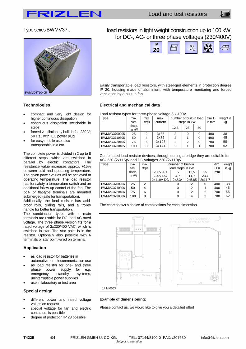
T422E r04 FRIZLEN GMBH U. CO KG. TEL: 07144/8100-0 FAX: /207630 [email protected] Subject to alteration
Load and test resistors
Type series BWMV37.. Technologies compact and very light design for
higher continuous dissipation continuous dissipation switchable in
steps forced ventilation by built-in fan 230 V;
50 Hz., with IEC power plug for easy mobile use, also
transportable in a car The complete power is divided in 2 up to 8 different steps, which are switched in parallel by electric contactors. The resistance value increases approx. +15% between cold and operating temperature. The given power values will be achieved at operating temperature. The load resistor has for safety a temperature switch and an additional follow-up control of the fan. The bolt- or flat-type terminals are mounted submerged (safe for transportation). Additionally, the load resistor has acid-proof rolls, gliding rails, and a trolley handle for better transportation. The combination types with 4 main terminals are usable for DC- and AC-rated voltage. The three phase version fits for a rated voltage of 3x230/400 VAC, which is switched in star. The star point is in the resistor. Optionally also possible with 6 terminals or star point wired on terminal. Application as load resistor for batteries in
automotive- or telecommunication use as load resistor for one- and three
phase power supply for e.g. emergency standby systems, uninterruptible power supplies
use in laboratory or test area Special design different power and rated voltage
values on request special voltage for fan and electric
contactors is possible degree of protection IP 23 possible
load resistors in light weight construction up to 100 kW, for DC-, AC- or three phase voltages (230/400V)
Easily transportable load resistors, with steel-grid elements in protection degree IP 20, housing made of aluminium, with temperature monitoring and forced ventilation by a built-in fan.
Electrical and mechanical data Load resistor types for three-phase voltage 3 x 400V
number of built-in load steps in kW
weight in kg
Type max. cont.
dissip. in kW
max. steps
max. current
12,5 25 50
dim. D in mm
BWMVD3700205 25 2 3x36 2 0 0 400 38BWMVD3710305 50 4 3x72 2 1 0 400 45 BWMVD3720405 75 6 3x10⁸ 2 2 0 700 55 BWMVD3730405 100 8 3x144 2 1 1 700 62
Combinated load resistor devices, through setting a bridge they are suitable for AC- 230 (2x115)V and DC voltages 220 (2x110)V
number of built-in load steps in kW
weight in kg
Type max. cont.
dissip. in kW
max. steps
230V AC 220V DC
2x110V DC
5 4,7
2x2,34
12,5 11,7
2x5,85
25 23,4
2x11,7
dim. D in mm
BWMVC3700206 25 2 0 2 0 400 38BWMVC3710306 50 4 0 2 1 400 45 BWMVC3720406 75 6 0 2 2 700 55 BWMVC3730606 100 8 0 4 2 700 62
The chart shows a choice of combinations for each dimension. Example of dimensioning:
Please contact us, we would like to give you a detailed offer!
BWMVD3710405
IP
20
14 M 0563

FRIZLEN GMBH U. CO KG. TEL: 07144/8100-0 FAX: /207630 [email protected] r04 T430E Subject to alteration
Load and test resistors
Type series FA.3../ FS.3..
Technologies continuous dissipation from 5 up to 60
kW switchable in parallel for higher
continuous dissipation for floor-level mounting or for mobile
applications optional with handgrip and steering rolls
for outdoor location (FS..) The necessary terminals are mounted on a terminal strip in the lower part of the device and are accessible after demounting a cover. The resistance value increases approx. +15% between cold and operating temperature. The given power values will be achieved at operating temperature. The load resistor can be chosen with star or delta wiring. On request we can build it for different voltages up to 3 x 690 V AC as well. Application An important application is the use as economic load resistor. Protection degree IP 20 is sufficient for installing in factory rooms, IP 23 is necessary for outdoor location. Special design different power steps or combinations
with higher power possible connection parts and enclosure out of
stainless steel 1.4301 mobile, for test area consoles for wall installation CEE-plug with cable and holder
load resistors in steel-grid design, self-ventilated, 5 – 60 kW, for 3 x 230/400V
FA...Steel-grid resistor unit, degree of protection IP 20, without weather-proof roof FS...Steel-grid resistor unit, degree of protection IP 23, with weather-proof roof
In completely closed zinc sheet enclosure with stationary safety guard at the top and bottom. Ceramic insulated flat or bolt terminals of 35 A up to 87 A in variable combinations for star and delta wiring are possible.
Electrical and mechanical data of load resistors
dimension in mm Type FA.3.. / FS.3..
max. typical
power in kW at
40°C and 100%ED
resistor value in
Ohm
current in A
A B C D
only IP23
weight in kg
F.. 31218.. 5,0 3 x 31,8 3 x 7,2 570 595 460 520 33F.. 31215.. 7,5 3 x 21,4 3 x 10,9 570 595 460 520 32 F.. 31221.. 10,0 3 x 16,0 3 x 14,5 570 595 460 520 35 F.. 31224.. 12,5 3 x 12,8 3 x 18 570 595 460 520 36 F.. 31330.. 15,0 3 x 10,6 3 x 22 770 795 460 520 49 F.. 31442.. 20,0 3 x 8,0 3 x 28,9 970 995 460 520 60 F.. 32351.. 25,0 3 x 6,4 3 x 36 770 795 710 770 78 F.. 32360.. 30,0 3 x 5,3 3 x 43,3 770 795 710 770 82 F.. 32472.. 35,0 3 x 4,6 3 x 51 970 995 710 770 93 F.. 32475.. 37,5 3 x 4,3 3 x 54 970 995 710 770 95 F.. 32481.. 40,0 3 x 4,0 3 x 58 970 995 710 770 98 F.. 33399.. 45,0 3 x 3,5 3 x 65 770 795 960 1100 111 F.. 33414.. 50,0 3 x 3,2 3 x 72 970 995 960 1100 124 F.. 33423.. 55,0 3 x 2,9 3 x 80 970 995 960 1100 134 F.. 33432.. 60,0 3 x 2,7 3 x 87 970 995 960 1100 138
This chart shows a choice of preferred power types. Other continuous dissipation, voltage and ohmic values are possible.
Example of dimensioning and selection of a specific unit: Type in star wiring FA 3121803 – 3 x 31.8, for 5 kW, 3 x 7,2 A
FSMS 3342303, in special design
IP
23 IP
20
FS(M).3..
Shown: Type series FS.. with weather-proof roof measure D (see left) is complete dimension + steering rolls (optional) Type series FA.. without weather-proof roof! measure C is complete dimension + steering rolls (optional) Steering rolls + handgrip (optional)
16M0614

T431E r04 FRIZLEN GMBH U. CO KG. TEL: 07144/8100-0 FAX: /207630 [email protected] Subject to alteration
Load and test resistors
Type series FAV 3../ FSV 3.. Technologies model for high power ratings with best
price-performance ratio power ventilated by integrated
230/400 V; 50 Hz axial flow fan for floor-level location continuous dissipation up to 250 kW paralleling of 2 or more units for
even higher dissipation for outdoor location (FSV) The necessary terminals are mounted on a terminal strip in the lower part of the device and are accessible after demounting a cover. By the use of steel-grid elements with a typical power of 1100 W per steel-grid with forced ventilation we cover a power range of up to 250 kW per unit. The resistance value increases approx. +15% between cold and operating temperature. The given power values will be achieved at operating temperature. You can achieve higher dissipations by installing several units in parallel. Appliction An important application is the use as load resistor for the testing of emergency standby power system. Protection degree IP 20 is sufficient for installing in factory rooms, IP 23 is necessary for outdoor location.
Special design with 2 temperature switches wired on
terminals special voltages of fan please ask for devices with higher
power ratings or other construction forms
mobile, for test area by rollers
load resistors in steel-grid design, forced ventilation, 70 – 250 kW, for 3 x 230/400 V
FAV... Steel-grid fixed resistor unit, degree of protection IP 20,
without weatherproof roof, air outlet on top, FSV... Steel-grid fixed resistor unit, degree of protection IP 23
with weatherproof roof, for outdoor location, air outlet at the side via air deflectors in the upper area.
In completely closed zinc sheet enclosure with barrier grid at the bottom and powered ventilation by an integrated ventilator. With air flow monitoring by wind indicator relay. Ceramic insulated flat or bolt terminals of 35A up to 400A in variable combinations available.
Electrical and mechanical data
dimension in mm max. weight in kg
Type FAV .. FSV ..
max. typical
power in kW at
40°C and 100% DCF
max. number of steel-grids corresp. to
given size of device A B C D E F
F.V 38568.. 75 68 1200 1240 800 700 795 770 142F.V 38602.. 110 102 1500 1540 800 700 795 770 185 F.V 38776.. 185 176 1400 1450 955 850 995 970 265 F.V 38864.. 250 264 1700 1750 955 850 995 970 370
This chart shows the size and the maximum power which can be built-in. You have much possibilities of combinations, depending on your needed power rating and your needed number of steps (examples see below). Standard load resistors for 3 x 230/400 V; 50 Hz Type series FAV..
power - steps
in kW
FAV 3856609 75FAV 3856612 37,5/37,5 FAV 3869009 100 FAV 3869612 50/50 FAV 3869618 10/20/20/50 FAV 3875609 175 FAV 3875612 75/100 FAV 3876818 50/50/50/25 FAV 3882209 250 FAV 3882212 150/100 FAV 3884021 5 x 50
Type series FSV..
power - steps
in kW
FSV 3856609 75FSV 3856612 37,5/37,5 FSV 3869009 100 FSV 3869612 50/50 FSV 3869618 10/20/20/50 FSV 3875609 175 FSV 3875612 75/100 FSV 3876818 50/50/50/25 FSV 3882209 250 FSV 3882212 150/100 FSV 3884021 5 x 50
16 M 0182
FSV 3889212
IP
23 IP
20
FAV..
16 M 0088
FSV..

FRIZLEN GMBH U. CO KG. TEL: 07144/8100-0 FAX: /207630 [email protected] r04 T432E Subject to alteration
Load and test resistors
Type series FAVR.3../FSVR.3..
Technologies model for high power ratings with best
price-performance ratio power ventilated by integrated
230/400 V; 50 Hz axial flow fan for floor-level location paralleling of 2 or more units for
even higher dissipation with integrated power contactors in
the attached switch cabinet to control the load steps
There are 2 possibilities to control the contactors of the individual load steps. Either by internal cam switches or by wiring the coils of contactors to terminals. The power connections in the switch cabinet are on terminals or on copper bars. By the use of steel-grid elements with a typical power of 1100 W per steel-grid with forced ventilation we cover a power range of up to 250 kW per unit. The resistance value increases approx. +15% between cold and operating temperature. The given power values will be achieved at operating temperature. Higher power ratings can be achieved by in parallel connection of several units. Application An important application is the use as load for the testing of emergency standby power systems or for use in test areas. Special design with wirewound lamina type fixed
resistors and the resistance value will change from cold to warm condition +/-1%
special voltages of fan enclosure and parts out of stainless
steel, switch cabinet varnished mobile, for test area by rollers
load resistors in steel-grid design, forced ventilation, 70 – 250 kW, with attached switch cabinet
FAV... Steel-grid fixed resistor unit, degree of protection IP 20, without
weatherproof roof, air outlet on top, FSV... Steel-grid fixed resistor unit, degree of protection IP 23
with weatherproof roof, for outdoor location, air outlet at the side via air deflectors in the upper area.
In completely closed zinc sheet enclosure with barrier grid at the bottom and powered ventilation by an integrated ventilator. With air flow monitoring by wind indicator relay. With attached switched cabinet for controlling the AC and DC loads. Control voltage 230 V AC or 24 V DC is possible. Electrical and mechanical data
dimension in mm max. weight in kg
Type FAV .. FSV ..
max. typical
power in kW at
40°C and 100% DCF
max. number of steel-grids corresp. to
given size of device
A B C E G
F.VR38568 75 68 1200 1240 800 795 1100 170F.VR38602 110 102 1500 1540 800 795 1100 220 F.VR38776 185 176 1400 1450 955 995 1350 310 F.VR38864 250 264 1700 1750 955 995 1350 410
This chart shows the size and the maximum power which can built-in. You have very much possibilities for combinations, depending from your needed power and your needed steps (e.g. below). Example for load resistors, e.g. AC/DC load Type FAVR..
power - steps
in kW for 3x400 V
FAVR385660 75FAVR385661 37,5/37,5 FAVR386900 100 FAVR386961 50/50 FAVR386961 10/20/20/50 FAVR387560 175 FAVR387561 75/100 FAVR387681 50/50/50/25 FAVR388220 250 FAVR388221 150/100 FAVR388402 5 x 50
Type FSVR..
power - steps
in kW for …DC
FSVR3867511 5/25/50 500 V FSVR3872019 12 x 10 400 V FSVRM3870712 10/20/20/50 Fahrbar 540 V FSVR3886411 50/100/100 500 V
We like to send you for your individual application an offer. Please send us the rated voltage and the preferred steps of the load..
FSVR mit Schaltschrank
IP
23 IP
20
FAVR(M).
16 M 0260, shown with option mobile
FSVR(M)..
16 M 0429, shown with option mobile

T433E r04 FRIZLEN GMBH U. CO KG. TEL: 07144/8100-0 FAX: /207630 [email protected] Subject to alteration
Load and test resistors
Further series:
1. FKK.. 3..
2. FAV 6../FSV6..
3. FALL 19..
4. FAL7../ FSL7..
Special characteristics:
- integrated in a duct section made by us, dimensions according to your specifications, Type FKKE
- for middle and higher dissipations up to 250 kW - an economic version when a local fan is available, e.g. by the
fan of a combustion engine - with steel-grid elements, the resistance value increases
between cold and operating temperature approx. +15% - with one or more resistor steps - built-in in a duct of the customer, Type FKKF… - optionally available with terminal box
see series T600E
- for continuous dissipation up to 250 kW - versions in protection degree IP 20 and IP23 possible - with wirewound resistor elements, constant ohmic value over a
big temperature range, resistance change +/-1%, also under load - with one or more resistor steps - controlling of the load steps in the attached switch cabinet, type
F.VR6.. - special voltages of fan - connections with flat or bolt terminals inside the housing - versions with low induction and with low noise possible - mobile version with handgrip and steering rollers,
see seriesT500E
- various continuous dissipation up to 4,5 kW built in one housing - in laboratory design - with wirewound resistor elements, constant ohmic value over a
big temperature range, resistance change +/-1%, also under load - with one or more resistor steps - also usable for higher currents, connections on flat clamp
terminals or safety sockets - also available as three phase version
see series T500E
- versions in protection degree IP 20 or IP23 - for continuous dissipation up to 30 kW - with wirewound resistor elements, constant ohmic value over a
big temperature range, resistance change +/-1%, also under load - with one or more resistor steps - connection with flat or bolt terminals inside the housing - versions with low induction and with low noise possible - mobile version with handgrip and steering rollers,
see series T500E

www.fr iz len.com
t100
t200
t300
t400
t500
t 5 0 0 – d i e M o d u L A r e N / t h e M o d u L A r o N e s
drahtgewickelte Lamellenfestwiderstände0,15 bis 30 Kilowatt
Drahtgewickelte Lamellenfestwiderstände als Einzelelemente, die ein-
baufähig sind und daraus aufgebaute Lamellenfestwiderstandsgeräte
in verschiedenen Schutz- und Befestigungsarten.
Anschluss an Litzen, Schraubschellen oder Klemmen,
Abgreifschellen möglich
Einzellamellen zu Baugruppen kombiniert für spezielle
Einbaulösungen in Schutzart IP00
Für Wand- oder Bodenmontage in Schutzart IP20 oder IP23
Thermisches Überstromrelais, Temperaturschalter oder FRIZLEN
DC-Powerswitch für thermische Überwachung und Abschaltung
Wirewound lamina type fi xed resistors0,15 up to 30 Kilowatt
Wirewound lamina type fi xed resistors as individual components, that
can be integrated into other units and composed lamina type fi xed
resistor units in different degrees of protection and mounting types.
Variable connections at wires, screw clips or terminals, with
or without adjustable clips
In degree of protection IP00 single elements can be combined
to units for special requirements
Up to degree of protection IP20 or IP23 for horizontal and
vertical mounting
Thermal overload relay, temperature switch or FRIZLEN
DC-Powerswitch for thermal monitoring and switch off

FRIZLEN GMBH U. CO KG. TEL: 07144/8100-0 FAX: /207630 [email protected] r04 T511E Subject for alteration
Lamina type fixed resistors
Contents
Properties
Applications
This list comprises wirewound lamina type fixed resistors as individual components in type series L and LB that can be integrated into other units. It also includes composed resistor units in different degrees of protection and mounting solutions. maximum characteristics type series page power survey T512E
technical details T513E
1,1 kW suitable for integration, can be combined L /LB T520E
3,0 kW compact construction form, 2 terminals FG /FGB /FGL T524E
3,0 kW thermal overload relay integrated FGT /FGBT /FGLT T525E
4,4 kW up to 10 teminals possible FGN /FGBN T526E
22 kW version of low noise and low inductance FGF T527E
4,5 kW adjustable clips possible as well as IP 23 FSL /FAL 16.. T529E
30 kW up to 30 teminals possible as well as IP 23 FSL /FAL 70.. T530E
250 kW different continuous steps, forced ventilation FAV /FSV 68.. T531E
low temperature coefficient
constant ohmic value over a large temperature range (s. p. T513E)
overload resistant at short time load
form-locking fixation
resistance value adjustable by adjustable clip
modification, adjustment or trimming on location (see type description)
flat construction form, various lengths and widths
can be integrated, various possibilities for connection and mounting (type series L / LB)
enclosure made from hot galvanised steel sheet
various protection and mounting types (all series besides L / LB)
low noise and low inductance version possible
used for apartment buildings, hospitals, opera houses and theatres (serialized with series FGF)
thermal overload relay available
integrated warning for high operating security (serialized with series FGT / FGBT / FGLT / FGFT)
intrinsically safe
to switch off the resistor safely by FRIZLEN DC POWERSWITCH (type series FGFX)
braking resistors for frequency converters and DC drives,
in low noise version suitable for hospitals and theatres
fixed resistors for power packs, batteries, UPS-units, generators
starting and regulating resistors for slip-ring rotor motors
starting resistors for DC motors
stator resistors for squirrel-cage motor
resistors for current limitation e.g. for charging and discharging of capacitors
integration into power supply units
protective resistors

T512E r04 FRIZLEN GMBH U. CO KG. TEL: 07144/8100-0 FAX: /207630 [email protected] Subject for alteration
Lamina type fixed resistors
Symbol
T 500 - survey
type series characteristics
page
L +
LB
T520E -
T523E
FG +
FGL
T524E
FGB
T524E
FGT FGBT FGLT
T525E
FGN +
FGBN
T526E
FGF. 610
- 614
T527E
- T528E
FSL 16 -
20
T529E
FAL 16 -
20
T529E
FSL 70 -
75 T530E
FAL 70 -
75
T530E
F.V 685
- 688
T531E
power from [kW] 0,15 0,25 0,37 0,25 1,5 4,0 0,25 0,25 2,5 2,5 75
power up to [kW] 1,11 3,0 1,5 3,0 4,4 22,0 4,5 4,5 30 30 250
max. number of terminals - 2 2 2 10 2 12 12 30 30 40
degree of protection IP00 X
degree of protection IP20 - if mounted on an appropriate surface
X X X X X
degree of protection IP20 X X X
degree of protection IP23 X X X
horizontal mounting X X X X X X X X
vertical mounting X X X X X X X
mounting not allowed X X X X X X X
temperature switch (optional) X X
thermal overload relay X X
FRIZLEN DC-POWERSWITCH X
adjustable clips possible X X X X X X X X
integration possible X
forced ventilation X
IP
23
IP
20
IP
20
IP
00
E
Rights for improvements and modifications of our products reserved. Modifications, errors and misprints justify no claim for damages.
We refer to our terms of sales and delivery.

FRIZLEN GMBH U. CO KG. TEL: 07144/8100-0 FAX: /207630 [email protected] r04 T513E Subject for alteration
Lamina type fixed resistors
Technical details
Construction
Resistance values/ Production tolerance/
Temperature dependency
Adjustable clips Taps
Time constant
Degrees of protection
Protective measures
Lamina type fixed resistors consist of support straps, ridged ceramic insulators and of resistor wiring. In standard version the strap is manufactured from a zinc plated steel sheet. We supply it with ridged ceramic insulators, grooved, made of ceramic (steatite C221), 60mm long, with pitches of 2mm, 3mm, 4mm and 5mm. For winding the resistors we use special wires made of CuNi 44 according to DIN 17471, 46460-1 and 46461 made of NiCr 3020 or CrAl 25 5 according to DIN 17470. The wires are fixed by the grooves on the ridged ceramic insulators in a non-slip way, even if they stretch when heated. The resistance values in the column “production range“ refer to our standard production range. Other values can be achieved if required. The normal tolerance is 10%. Smaller tolerances upon request. The resistance value will change slightly in dependency of the winding temperature. With T 300 K the resistance will change compared to a cooled down condition as follows: with wires from CuNi 44 approx. ±1%, made of CrAl 25 5 approx. +1% and made of NiCr 3020 approx. +10%. Lamina type fixed resistors of type series L and LB can be provided with adjustable clips in order to adjust to the resistor values. The same applies to some type series of our composed units. Others can be provided with fixed taps wired on terminals. The medium thermal time constant is 150 s. Correlation of type series and degrees of protection according to EN 60529 and/or DIN VDE 0470 part 1
Type series
Degree of protection
First digit degree of protection against access & solid foreign objects
Second digit degree of protection against water
L LB FK..
IP 00 Non-protected – i.e. depending upon integration the user must provide a protection
Non-protected
FG.. FGB.. FGF..
IP 20
Non-protected
FAL.. FAV..
IP 20
Non-protected
FSL.. FSV..
IP 23
Protected against access to hazardous parts with a finger and against solid foreign objects of 12,5mm and greater.
Protected against spraying water. Water sprayed at an angle up to 60° on either side of the vertical shall have no harmful effects
if mounted on an appropriate surface – i.e. mounted on a surface according to degree of protection IP 20 or higher All our power resistors of degree of protection IP 20 or higher correspond to safety class I, i.e. we provide connections for protective earth conductors according to EN 61140. Devices of degree of protection IP 20 or higher correspond to the CE low voltage directive. Power resistors being passive electronical or electrical units are not affected by the specific EMC standards. They do not produce any interfering radiations nor are they affected.
IP
00 IP
20
IP
20 IP
23

T514E r04 FRIZLEN GMBH U. CO KG. TEL: 07144/8100-0 FAX: /207630 [email protected] Subject for alteration
Lamina type fixed resistors
Air- and Creepage distance
Excess current protection
Excess temperature protection
Intrinsically safe version with Frizlen
DC-POWERSWITCH
Contact rating
Storage temperature/ Operation temperature/
Installation altitude
Air and creepage distances are rated according to IEC 664 (DIN EN 0110 part 1) for the overvoltage category III and degree of pollution 3 for grounded three-phase mains supplies up to 3 x 500 V. Testing voltage 2.5 kV AC. These data are valid for all devices that are connected to mains voltage and derived voltages, as for example the intermediate circuit voltage of frequency converters. Do not conclude from the calculated relation between the rated power and the maximum producible ohmic value to the rated voltage! A protection of the resistors against overloading or excess temperature - as demanded in standards - can be realized with the help of a thermal overload relay provided by the user. The set current must correspond to the rated current of the resistor, that is calculated according to continuous duty power and resistance value corresponding to Ohm's law (formula: see "terminal details" p. T517E). Concerning the series FGT, FGBT, FGLT and FGFT the thermal overload relay is a component of the device - with exceeding of the rated current a signal contact is released. There will not be a disconnection of the resistor. Resetting by hand. Another kind of the excess temperature monitoring, particularly suited for long-term overloading, is the equipment with a temperature switch. In IP 20/23-resistor devices it is wired on terminals, in IP 00 resistors the switch is directly connectable and releases a signal contact when the set temperature is exceeded. There will not be a disconnection of the resistor. See type series FGF.Q and F.VQ. You can inform yourselfs about function and restrictions by our data sheet „Tripping of monitoring devices“. We can send it to you on request. Integrated overload switch for a maximum of 850 VDC to protect the resistor. It protects the integrated resistor against constant overload and against too high short time peak power, e.g. caused by a false operational mode or a fault by an short circuited chopper transistor. Possible damage in the environment by overheating and burning are effectively avoided.
So you receive an intrinsically safe resistor protection degree even for IP20. The FRIZLEN DC-POWERSWITCH can also be integrated in the switch cabinet. After a successful fault clearance the DC-POWERSWITCH can be switched on like a normal automatic cutout. We can send you more technical details and characteristics on request. Attention: Frizlen DC-POWERSWITCH are only suited for monitoring and disconnecting from DC-voltage with pure resistive load (DC1) up to 850 VDC. Contact ratings of the signal contacts of temperature switches and thermal overload relays. 2 A / 24 VDC (DC11) 2 A / 230 VAC (AC11) Contact ratings of the signal contacts of the DC-Powerswitch: 5 A / 24 VDC (DC11) 10 A / 230 VAC (AC11) Storage temperature: - 40° C to 80° C Operation temperature: - 30° C to 40° C. If the ambient temperature is higher than
40°C, you have to decrease the continuous dissipation by 4% per 10 K temperature rise!
Installation altitude: 2000 m above sea level, you have to decrease the continuous dissipation for 10% per 1000 m altitude, maximum altitude 5000 m above sea level
Restrictions are to be made for the type series FGFT. and FGFX. because of the built-in monitoring device. Operation temperature: - 20° C to 40° C.
RES
RB1 RB2 T2 T1

FRIZLEN GMBH U. CO KG. TEL: 07144/8100-0 FAX: /207630 [email protected] r04 T515E Subject for alteration
Lamina type fixed resistors
Ventilation / Temperatures
The given typical power values are valid for 100% duty cycle factor (DCF) (continuous dissipation) under the following conditions: temperature rise of 200 K at the surface of fixed resistor enclosures (degree of
protection> IP00) temperature rise of 300 K at the surface of fixed resistor elements (degree of
protection IP00). unhindered access of cooling air unhindered diverting of warmed up air (mind a minimum separation distance of
approx. 200 mm to neighbouring components/walls and of approx. 500 mm to components above/ceiling)
Since electrical energy is converted into heat, heating up of the exhaust air and of the enclosure at the air outlet is inevitable. The highest temperature with typical power may be maximum 200°C above the ambient temperature. Since the cooling of the devices is accomplished by convection and/or forced ventilation (series FAV/ FSV), the above mentioned aspects have absolutely to be considered. In cases of insufficient cooling or false mounting the resistor or the surrounding construction units could be overheated or ruined. Depending upon use it can be possible to increase the continuous dissipation of the resistors, if higher temperatures are accepted. With an increase of e.g. 130% of the typical power you will have a rise in temperature of 350K at the surface of the resistor. In other cases of application the continuous dissipation must be reduced, for example with temperature sensitive devices in the surrounding area. The dependence between temperature rise and actual continuous dissipation is shown in the diagram below.
Normal operation range (up to 130%):
Recommended operation range for maximum product life and failure free operation Allowable threshold (up to 160%):
Allowable operation range, danger of shorter product life and higher failure probability Unallowable operation range (more than 160%):
Danger of excessive heat and destruction of resistor and neighbouring components
0
100
200
300
400
500
0 50 100 150 200 250
Continuous dissipation in % of typical power
Exc
ess
tem
per
atu
re [
K]
Excess temperature in dependence of continuous dissipation
At the resistor element
normal operation range
allowable threshold unallowable operation range
At the enclosure surface

T516E r04 FRIZLEN GMBH U. CO KG. TEL: 07144/8100-0 FAX: /207630 [email protected] Subject for alteration
Lamina type fixed resistors
Short time dissipation/ Total cycle time/
Duty cycle factor(DCF)
Overload factor (OLF)
Calculation example given:
wanted: continuous dissipation
At many applications resistors are not loaded in continuous but in short time operation. In the following you will find indications, how to calculate the allowable short time dissipation with the help of the duty cycle factor (DCF) and the overload factor (OLF). If the DCF factor is not known, it can be calculated as follows:
warning: The total cycle time may be maximum 120 s - shorter total cycle times are possible. The total cycle times for motors are mostly higher than 120 s By comparison of the known DCF-factor with the following diagram or table you can work out the overload factor (OLF) and/or the continuous and the short time dissipation.
ED 1% 3 % 6% 15% 25% 40% 60% 80% 100% ÜF 22 13 8,2 4,2 3,0 2,2 1,5 1,12 1,0
The continuous and the short time dissipation can be calculated as follows:
Resistor with a short time dissipation of 50 kW for 30 s and a total cycle time of
120s The duty cycle factor (DCF) is 30 s : 120 s x 100% = 25% Overload factor (OLF) for 25% DCF, according to table it is 3,0 The continuous dissipation is 50 kW : 3,0 = 16,7 kW; You need a resistor with a continuous dissipation of at least 16,7 kW!
Total cycle time = 120 s
ton = 48 s
Total cycle time = 30 s
ton = 7,5 s
%404,0120
481
s
sED %2525,0
30
5,72
s
sED
Overload factor (OLF) in dependence of duty cycle factor (DCF)(Total cycle time = 120s)
DCF
OL
F -
of l
am
ina
typ
e re
sist
ors
1% 6% 10% 20% 40% 60% 100%
20
10
3
1
timecycleTotal
ttimeonSwitchDCFfactorcycleDuty on)(
OLFndissipatioContinuousndissipatiotimeShort
OLFfactorOverload
ndissipatiotimeShortndissipatioContinuous

FRIZLEN GMBH U. CO KG. TEL: 07144/8100-0 FAX: /207630 [email protected] r04 T517E Subject for alteration
Lamina type fixed resistors
Terminal details/ Monitoring devices/
Cross section
Wiring
Mounting
Rated current and cross section of terminals and monitoring types. Type abbreviation rated
current in A with 100%
DCF
rated current in A with 40%
DCF
maximum cross section
porcelain terminal
PK 16 up to 2,5 mm²
ceramic flat terminal
FK 35 44 2,5 - 10 mm²
G 5 30 38 0,5 – 2,5 (4) mm²
AWG 24 - 12 device terminal out of Polyamid (PA) G 10 60 75
0,5 – 10 (16) mm² AWG 20 - 6
BK M6 60 75 BK M8 115 143 BK M10 220 287
bolt terminals out of ceramic
BK M12 400 536
cross section depending on lug size with
corresponding hole
ST2,5 20 25 up to 2,5 mm²; AWG 16 -
12 cage clamp terminal out of PA
ST 4 30 38 up to 4,0 mm²; AWG 20 –
10
signal contact 2 - up to 2,5 mm²; AWG 16-
12 thermal overload relay main
connection bis 13/24/80 17/30/100 2,5/4/25 mm²; AWG 20 - 6
signal contact 10 - up to 1,5 (2,5) mm²; AWG
16 - 12 DC-POWER-SWITCH FPS main
connection 40 50 up to 16 mm²; AWG 4
The values in the brackets are valid for solid conductor or single wired. The rated current is calculated in each case due to Ohm`s law as follows:
whereas P is the power of the resistor and R is the value of the resistance
If terminals are required, the connections are wired by means of flexible, heat resistant, silicone-insulated wire on a terminal strip that is located in the lower and/or front part of the equipment within the area of the entering cooling air. If the wiring is accomplished by the user, make sure that a heat resistant wire is used. With the series F.L 7.. as well as with F.V 68.. there is an undrilled cable entry strip in the lower part. It can be provided by the user with appropriate drillings for cable glands as strain relief. Please mind the mounting indications in the corresponding type series! You will find these icons in the data sheets: Allowable: On horizontal surfaces Allowable: On vertical surfaces terminals at the bottom Not allowable: On vertical surfaces terminals at the top, left or right Allowable: On vertical surfaces
R
PI

T520E r04 FRIZLEN GMBH U. CO KG. TEL: 07144/8100-0 FAX: /207630 [email protected] Subject for alteration
Lamina type fixed resistors
Type series L / LB Technologies particularly flat design suitable for integration assembled units possible various lengths and widths,
therefore many specifications depending on requirement
continuous dissipation up to 1110 W adjustable clips are available for
both type series Application brake resistor load resistor protection resistor
150 – 1110 W with connection at wires, lugs or screw clips
Wirewound lamina type fixed resistors, degree of protection IP 00 with ridged ceramic insulators from steatite. Standard version with straps from zinc plated steel in 2 widths: type series L.. (standard version) type series LB.. (wide version) Connection types and versions We provide three versions with various connection types With wires, version L.. D and LB.. D With lugs and connecting screws, version L.. and LB.. With screw clips, version.L.. C and LB.. C The last two can also be provided with adjustable clips Version L.. D and LB.. D lamina type fixed resistors with connection at 2 hard soldered wires. Standard version (if no other data): Silicone insulated wire (SIF), cross section 1,5 mm², length of wires D1 and D2 500 mm each. Suitable for all resistance values. Version L.. and LB.. lamina type fixed resistors with 2 wire lugs as connection points, which are provided with M5 screw combinations for the connection. Only suitable for resistance wires from cross section 0,8 mm on! Version L.. F and LB.. F With one or several adjustable clips, that can be modified (F, 2F, 3F, 4F) Example: LB5 2F- 21, wide lamina LB5 with 2 adjustable clips and 21 . Version L.. C and LB.. C lamina type fixed resistor with 2 screw clips as end clips, that are prepared with M5 screw combinations for the connection. Suitable for all resistance values. Version L.. C.F and LB.. C.F With one or several adjustable clips, that can be modified (CF, C2F, C3F, C4F) Example: L10 CF - 150, standard lamina L10 with 1 adjustable clip and 150 .
D1 D2
Special versions of the support strap from aluminium or stainless steel for a low noise and low inductance
version from zinc plated perforated steel sheet for a better ventilation when
incorporated horizontally or into units with forced ventilation. With special dimensions to perfectly suit the requirements of the
application
L2 D
IP
00 E

FRIZLEN GMBH U. CO KG. TEL: 07144/8100-0 FAX: /207630 [email protected] r04 T521E Subject for alteration
Lamina type fixed resistors
Type series L / LB Options to perform the connection wires for version L..D, LB..D 1. Insulation and cross section of wires
In standard version wires are silicone insulated (SIF) with a cross section of 1,5 mm², colour black Continuous temperature +180°C (for a short time 200°C) We can deliver the following variations with additional charge: Silicone insulated wire cross section 2,5 mm², colour black (only available for resistance wires from diameter 1,2mm
on) Teflon insulated wire FEP (silicone free), cross section 1,5 mm², colour transparent, continuous temperature 205°C Teflon insulated wire FEP/UL, UL approved (UL 1330), cross section AWG14 (equal to 2,08 mm²), colour white with
UL-print, continuous temperature 200°C silicone- and Teflon free wire name brand Radox 155, UL approved (UL 3298), cross section AWG14, colours yellow,
red or blue, continuous temperature 155°C
2. Lengths of wires
In standard version wires D1 and D2 are both 500 mm long , but can be modified and provided in various lengths. 3. Equipment of the open wire endings (connection provided for the customer)
In standard version wires are not bared and not equipped with connection devices. For an additional charge we provide: lugs M4 or M5, blank or insulated with heat shrink tubing fast-on connections 6,3 x 0,8 straight or angled, blank or with enclosure conductor sleeves, blank bi- or multi-pole plugs for easy connection by the user
4. Resistor taps
For special applications we provide further connection wires as fixed taps. 5. How to order
If you want to modify our standard version please specify the connection wires as follows (example): wire D1 : Radox 155 – Insulation, AWG 14, 300 mm long, yellow, with conductor end sleeve blank wire D2 : Radox 155 – Insulation, AWG 14, 400 mm long, blue, with fast-on connection 6,3 x 0,8 blank, straight Combinations of several lamina type fixed resistors to form a unit
Several laminas can be combined by brackets or threaded bolts to form units ready to connect and to integrate By a range of enclosures or partial enclosures we provide all kinds of ducts for better ventilation and screening against heat
sensitive parts Examples of constructions
Unit consisting of 2 paralleled laminas L4
The laminas are combined by threaded bolts to a unit
Three-side cover, can be used for mounting
Wire connection and lugs M5 (with heat shrink tubing)
Unit consisting of 2 laminas L4 connected in series
The laminas are combined by brackets to a unit
Wire connection with straight fast-on connection 6,3 x 0,8 in an enclosure
Unit consisting of 4 laminas L3 connected in series
The laminas are combined by threaded bolts to units
Wire connection and lugsM4 (with heat shrink tubing)

T522E r04 FRIZLEN GMBH U. CO KG. TEL: 07144/8100-0 FAX: /207630 [email protected] Subject for alteration
Lamina type fixed resistors
Type series L The selection of the windings below is based upon economical aspects. Other windings with an increased weight of the wire for better energy absorption capacity or different ohmic values on request. The given power in W refers to individual mounting, ventilation and unhindered access of air for 100% DCF (continuous dissipation). The power has to be reduced by the factor 1,21 when several laminas are combined or when integrated into an enclosure.
type L2 L3 L4 L5 L6 L7 L8 L9 L10
power [W] at 40°C and 100% ED 150 235 300 380 460 535 610 690 760 Dimension A [mm] 140 210 260 340 390 445 520 560 620 Dimension B [mm] 155 225 275 355 405 460 535 575 635
type of resistor wire
alloy [mm]
pitch of ridged
ceramic insulators
[mm]
resistance values in
CrAl 25 5 0,5 2 54 84 115 145 176 207 237 268 299 CrAl 25 5 0,55 2 45 70 96 121 147 172 198 223 249 CrAl 25 5 0,6 2 38 60 81 102 124 145 167 188 210 CrAl 25 5 0,65 2 32 50 68 86 104 122 140 158 177 NiCr 30 20 0,6 2 28 43 58 73 90 104 120 135 150 NiCr 30 20 0,65 2 24 36 49 62 76 89 103 115 128 NiCr 30 20 0,7 2 20 31 43 54 66 77 89 100 111 NiCr 30 20 0,75 2 18 27 37 47 57 67 77 87 96 NiCr 30 20 0,8 2 16 24 33 41 50 59 68 76 85 CuNi 44 0,6 2 12 20 27 34 41 49 56 63 71 CuNi 44 0,65 2 11 17 23 29 35 42 48 54 60 CuNi 44 0,7 2 9,2 14 20 25 30 36 41 46 52 NiCr 30 20 0,9 3 8,0 13 17 22 26 31 36 40 45 NiCr 30 20 1,0 3 6,4 10 14 18 21 25 29 32 36 NiCr 30 20 1,1 3 5,4 8,4 12 15 18 21 24 27 30 NiCr 30 20 1,2 3 4,5 7,1 9,7 13 15 17 20 23 25 CuNi 44 0,9 3 3,8 5,9 8,1 10 12 14 16 19 21 CuNi 44 1,0 3 3,1 4,8 6,6 8,3 10 11 13 15 17 CuNi 44 1,1 3 2,5 4,0 5,4 6,9 8,3 9,8 11 12 14 CuNi 44 1,2 3 2,1 3,3 4,6 5,8 7,0 8,2 9,4 10 11 CuNi 44 1,3 3 1,9 2,9 4,0 5,0 6,1 7,1 8,2 9,2 10 CuNi 44 1,4 3 1,5 2,5 3,3 4,2 5,1 6,0 6,9 7,8 8,7 CuNi 44 1,3 4 1,4 2,2 3,0 3,8 4,6 5,4 6,2 7,0 7,8 CuNi 44 1,4 4 1,2 1,9 2,5 3,2 3,9 4,5 5,2 5,9 6,5 CuNi 44 1,5 4 1,0 1,6 2,2 2,8 3,4 4,0 4,5 5,1 5,7 CuNi 44 1,6 4 0,92 1,4 2,0 2,5 3,0 3,5 4,0 4,5 5,0 CuNi 44 1,7 4 0,83 1,3 1,8 2,2 2,7 3,1 3,6 4,1 4,5 CuNi 44 1,6 5 0,73 1,1 1,5 2,0 2,4 2,8 3,2 3,6 4,0 CuNi 44 1,7 5 0,65 1,0 1,4 1,8 2,1 2,5 2,9 3,2 3,6 CuNi 44 1,8 5 0,57 0,89 1,2 1,5 1,9 2,2 2,5 2,8 3,2 CuNi 44 1,9 5 0,52 0,81 1,1 1,4 1,7 2,0 2,3 2,6 2,9 CuNi 44 2,0 5 0,46 0,72 0,98 1,2 1,5 1,8 2,0 2,3 2,6
Example of dimensioning and selection of a special unit: lamina type fixed resistor 380 W , resistance value 10 , with connection at screw clips, with an additional adjustable clip: selected: L 5 CF – 10
L 5 C F - 10 ohmic value 10%
adjustable clip version size type series
version L .. D L .. and L.. F L .. C and L .. C.F
15 M 0083 15 M 0345 15 M 0084
adjustable clip „F“ optional
M5x12

FRIZLEN GMBH U. CO KG. TEL: 07144/8100-0 FAX: /207630 [email protected] r04 T523E Subject for alteration
Lamina type fixed resistors
Type series LB The selection of the windings below is based upon economical aspects. Other windings with an increased weight of the wire for better energy absorption capacity or different ohmic values on request. The given power in W refers to individual mounting, ventilation and unhindered access of air for 100% DCF (continuous dissipation). The power has to be reduced for the factor 1,21 when several laminas are combined or when integrated into an enclosure.
type LB2 LB3 LB4 LB5 LB6 LB7 LB8 LB9 LB10
power [W] at 40°C and 100% ED 220 345 445 555 665 785 895 1000 1110 dimension A [mm] 140 200 260 320 380 440 500 560 620 dimension B [mm] 155 215 275 335 395 455 515 575 635
Type of resistor wire
alloy [mm]
pitch of ridged
ceramic insulators
[mm]
resistance values in
CrAl 25 5 0,8 3 21 32 44 56 68 80 92 103 115 CrAl 25 5 0,9 3 16 26 35 44 53 63 72 81 91 CrAl 25 5 1,0 3 13 21 28 36 43 51 59 66 74 NiCr 30 20 0,9 3 12 18 25 32 39 45 52 59 66 NiCr 30 20 1,0 3 9,5 15 20 26 31 37 42 47 53 NiCr 30 20 1,1 3 7,8 13 17 21 26 30 35 39 44 NiCr 30 20 1,2 3 6,6 11 14 18 22 25 29 33 37 CuNi 44 0,9 3 5,5 8,7 11 15 18 21 24 28 31 CuNi 44 1,0 3 4,4 7,0 9,5 12 14 17 20 22 25 CuNi 44 1,1 3 3,7 5,8 7,9 10 12 14 16 18 21 CuNi 44 1,2 3 3,1 4,9 6,7 8,4 10 12 13 15 17 CuNi 44 1,3 3 2,7 4,2 5,8 7,3 8,9 10 12 13 15 CuNi 44 1,4 3 2,3 3,6 4,9 6,2 7,5 8,8 10 11 12 CuNi 44 1,3 4 2,1 3,2 4,4 5,6 6,7 7,9 9,0 10 11 CuNi 44 1,4 4 1,8 2,7 3,7 4,7 5,7 6,6 7,6 8,6 9,6 CuNi 44 1,5 4 1,5 2,4 3,2 4,1 4,9 5,8 6,6 7,5 8,3 CuNi 44 1,6 4 1,3 2,1 2,9 3,6 4,4 5,1 5,9 6,6 7,4 CuNi 44 1,7 4 1,2 1,9 2,6 3,3 3,9 4,6 5,3 6,0 6,6 CuNi 44 1,6 5 1,0 1,7 2,3 2,9 3,4 4,0 4,6 5,8 5,8 CuNi 44 1,7 5 0,95 1,5 2,0 2,6 3,1 3,7 4,2 4,7 5,3 CuNi 44 1,8 5 0,83 1,3 1,8 2,3 2,7 3,2 3,7 4,2 4,6 CuNi 44 1,9 5 0,76 1,1 1,6 2,1 2,5 2,9 3,4 3,8 4,2 CuNi 44 2,0 5 0,67 1,0 1,4 1,8 2,2 2,6 3,0 3,4 3,7
Example of dimensioning and selection of a special unit: lamina type fixed resistor 1000 W ,resistance value 15 , with connection at 2 hard soldered joint wires of following lengths: wire D1 = 800 mm and wire D2 = 1000 mm, version with silicone insulated wire, cross section 1,5 mm² selected: LB 9 D – 15, wire D1: 800; wire D2: 1000
LB 9 D - 15 D1: 800; D2: 1000
ordering designation ohmic value 10% version size type series
version LB .. D LB .. and LB.. F LB .. C and LB .. C.F
15 M 0083 15 M 0345 15 M 0084
M5x12
adjustable clip „F“ optional

T524E r04 FRIZLEN GMBH U. CO KG. TEL: 07144/8100-0 FAX: /207630 [email protected] Subject for alteration
Lamina type fixed resistors
Type series FG / FGB / FGL Technologies flat construction form continuous dissipations up to
3,0 kW Wall mounting or mounting on the
switch cabinet adjustable clips available for all type
series, besides FGB up to 20A 2-pole porcelain terminal up to 35A 2-pole flat terminal The given power rating values are valid for 100% DCF (continuous dissipation). For short time operation you will find the values in the following table as a function of the duty cycle factor (DCF). Just multiply by the corresponding overload factor (OLF).
ED 60% 40% 25% 15% 6%
ÜF 1,5 2,2 3,0 4,2 8,2 These overload factors are valid for a total cycle time of maximum 120 s. You will find further details in chapter Technical Details, pages T513E - T517E. There are various applications for wall mounting or mounting on the switch cabinet because of the flat and compact construction. An important application is the use as braking resistor for motor/generator drive of motors with frequency converters. Special design Version of low inductance and low
noise (support strap from aluminium or stainless steel)
version with degree of protection IP00 type series FK / FKB / FKL on request
0,25 – 3,0 kW with 2 terminals
Wirewound lamina type fixed resistor, degree of protection IP 20 in zinc plated steel sheet enclosure with 2 terminals and PG11-cable gland in attached terminal box.
mounted on an appropriate surface
Electrical and mechanical data
power in kW at 40°C and
100% DCF
production range
value
number of
laminas and size
dimensions in mm max.weight in kg
type
from
up to
L M R U O
FG 2 0,25 0,23 40 2 L2 140 184 92 64 240 1,3FG 3 0,39 0,36 62 2 L3 210 254 92 64 310 1,7 FG 4 0,50 0,49 86 2 L4 260 304 92 64 360 2,4 FG 5 0,63 0,62 100 2 L5 340 384 92 64 440 2,6 FG 6 0,75 0,75 130 2 L6 390 434 92 64 490 2,8 FG 7 0,90 0,90 150 2 L7 445 489 92 64 545 3,0 FG 8 1,00 1,0 170 2 L8 520 564 92 64 620 3,5 FGB 2 0,37 0,34 24 2 LB2 140 184 92 64 240 1,5 FGB 3 0,57 0,53 36 2 LB3 200 254 92 64 310 1,9 FGB 4 0,74 0,72 50 2 LB4 260 304 92 64 360 2,6 FGB 5 0,92 0,90 64 2 LB5 320 364 92 64 420 2,8 FGB 6 1,10 1,1 78 2 LB6 380 434 92 64 490 3,0 FGB 7 1,30 1,3 90 2 LB7 440 489 92 64 545 3,4 FGB 8 1,50 1,5 100 2 LB8 500 544 92 64 600 4,0 FGL 640402 1,00 1,0 170 4 L4 260 300 185 150 360 4,0 FGL 660402 1,50 1,5 260 4 L6 390 430 185 150 490 5,0 FGL 680402 2,00 2,0 350 4 L8 520 560 185 150 620 6,0 FGL 660602 2,20 2,2 390 6 L6 390 430 275 240 490 7,0 FGL 680602 3,00 3,0 530 6 L8 520 560 275 240 620 9,0
Example of dimensioning and selection of a specific unit:
Monophase braking resistor for drive with frequency converter, short time power: 8 kW at 6% DCF, total cycle time shorter than 120 s, intermediate circuit voltage 650 V; resistance value 50 ; Calculation of the continuous dissipation: 8kW : 8,2 = 0,98 kW. selected: FG 8 – 50 with continuous dissipation 1kW
FG 8 - 50 ohmic value 10% size type series
15 M 0155
FG 6
IP
20
MM

FRIZLEN GMBH U. CO KG. TEL: 07144/8100-0 FAX: /207630 [email protected] r04 T525E Subject for alteration
Lamina type fixed resistors
Type series FGT / FGBT / FGLT Technologies integrated thermal overload relay up
to 24 A with thermal protection connections directly at the overload
relay current is adjusted Wall mounting or mounting on the
switch cabinet Thermal overload relay The thermal overload relay is mounted in the attached terminal box and may signal an overloading of the resistor. This is done by contacts normally closed/opened free of potential (NC/NO). This signal has to be considered by the customer, e.g. by warning or net side disconnection. Warning: There will not be a disconnection of the resistor! Cross sections / cable glands:
connection in mm² fine stranded, for relays up to 13A 24A main current 1 x 2,5 2 x 6 auxiliary curr. 1 x 2,5 2 x 2,5 Cable glands PG9 +
PG11 M12 + PG16
Contact rating of the signal contacts:
2 A / 24 VDC (DC11) 2 A / 230 VAC (AC11) Application Braking resistors for motor/generator drive of motors with frequency converters with monitoring of the current. Special design Version of low inductance and low
noise (support strap from aluminium or stainless steel)
0,25 – 3,0 kW with 2 terminals
Wirewound lamina type fixed resistor, degree of protection IP 20 in zinc plated steel sheet enclosure. Cable glands and as well as thermal overload relay in attached terminal box.
mounted on an appropriate surface
Electrical and mechanical data
dimensions in mm
overload
relay up to
production range
value
13A 24A
type power in kW
at 40°C and
100%DCF from
up to
# of lamina
and size
L M R U O O
max. weight in kg
FGT 2 0,25 0,2 40 2 L2 140 184 92 64 260 293 1,9FGT 3 0,39 0,3 62 2 L3 210 254 92 64 330 363 2,3 FGT 4 0,50 0,4 86 2 L4 260 304 92 64 380 413 3,0 FGT 5 0,63 0,6 100 2 L5 340 384 92 64 460 493 3,2 FGT 6 0,75 0,7 130 2 L6 390 434 92 64 510 543 3,4 FGT 7 0,90 0,9 150 2 L7 445 489 92 64 565 598 3,7 FGT 8 1,00 1,0 170 2 L8 520 564 92 64 640 673 4,1 FGBT 2 0,37 0,4 24 2 LB2 140 184 92 64 260 293 2,1 FGBT 3 0,57 0,6 36 2 LB3 200 254 92 64 330 363 2,5 FGBT 4 0,74 0,8 50 2 LB4 260 304 92 64 380 413 3,2 FGBT 5 0,92 0,9 64 2 LB5 320 364 92 64 440 473 3,4 FGBT 6 1,10 1,1 78 2 LB6 380 434 92 64 510 543 3,6 FGBT 7 1,30 1,3 90 2 LB7 440 489 92 64 565 598 4,0 FGBT 8 1,50 1,5 100 2 LB8 500 544 92 64 620 653 4,6 FGLT 640402 1,00 1,0 170 4 L4 260 300 185 150 380 413 4,6 FGLT 660402 1,50 1,5 260 4 L6 390 430 185 150 510 543 5,6 FGLT 680402 2,00 2,0 350 4 L8 520 560 185 150 640 673 6,6 FGLT 660602 2,20 2,2 390 6 L6 390 430 275 240 510 543 7,6 FGLT 680602 3,00 3,0 530 6 L8 520 560 275 240 640 673 9,6
Example of dimensioning and selection of a specific unit:
Monophase braking resistor for drive with frequency converter, short time power: 8,4 kW at 15% ED, , total cycle time shorter than 120 s, intermediate circuit voltage 650V; resistance value 50 ; calculation of the continuous dissipation: 8,4 kW : 4,2 = 2 kW selected: FGLT 680402 – 50 with continuous dissipation 2 kW
FGLT 68 04 02 - 50 ohmic value 10%; set current 6,4A number of terminals number of laminas size type series
15 M 0118 (13A; PG9+PG11) + 15 M 0119 (24A; M12+PG16)
FGBT 6
IP
20
MM
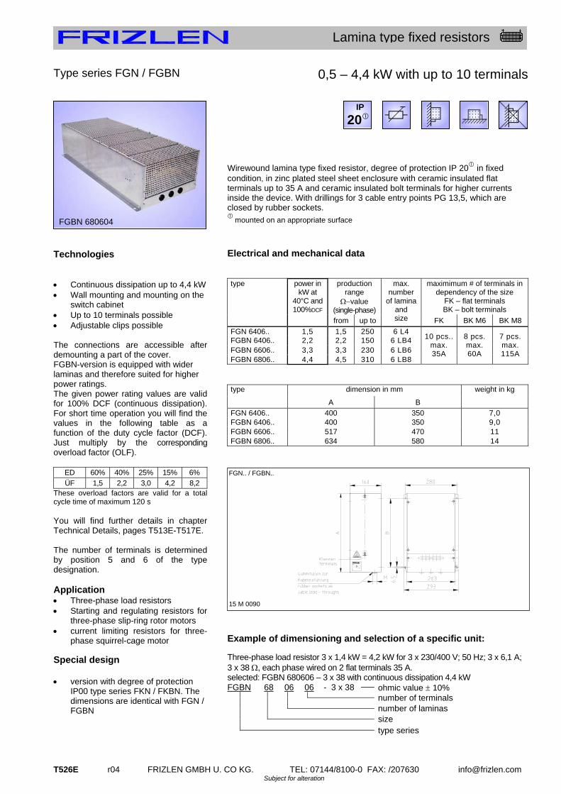
T526E r04 FRIZLEN GMBH U. CO KG. TEL: 07144/8100-0 FAX: /207630 [email protected] Subject for alteration
Lamina type fixed resistors
Type series FGN / FGBN Technologies Continuous dissipation up to 4,4 kW Wall mounting and mounting on the
switch cabinet Up to 10 terminals possible Adjustable clips possible The connections are accessible after demounting a part of the cover. FGBN-version is equipped with wider laminas and therefore suited for higher power ratings. The given power rating values are valid for 100% DCF (continuous dissipation). For short time operation you will find the values in the following table as a function of the duty cycle factor (DCF). Just multiply by the corresponding overload factor (OLF).
ED 60% 40% 25% 15% 6%
ÜF 1,5 2,2 3,0 4,2 8,2 These overload factors are valid for a total cycle time of maximum 120 s You will find further details in chapter Technical Details, pages T513E-T517E. The number of terminals is determined by position 5 and 6 of the type designation. Application Three-phase load resistors Starting and regulating resistors for
three-phase slip-ring rotor motors current limiting resistors for three-
phase squirrel-cage motor Special design version with degree of protection
IP00 type series FKN / FKBN. The dimensions are identical with FGN / FGBN
0,5 – 4,4 kW with up to 10 terminals
Wirewound lamina type fixed resistor, degree of protection IP 20 in fixed condition, in zinc plated steel sheet enclosure with ceramic insulated flat terminals up to 35 A and ceramic insulated bolt terminals for higher currents inside the device. With drillings for 3 cable entry points PG 13,5, which are closed by rubber sockets.
mounted on an appropriate surface
Electrical and mechanical data
production range
value (single-phase)
maximimum # of terminals in dependency of the size
FK – flat terminals BK – bolt terminals
type power in kW at
40°C and 100%DCF
from up to
max. number
of lamina and size FK BK M6 BK M8
FGN 6406.. 1,5 1,5 250 6 L4 FGBN 6406.. 2,2 2,2 150 6 LB4 FGBN 6606.. 3,3 3,3 230 6 LB6 FGBN 6806.. 4,4 4,5 310 6 LB8
10 pcs.. max. 35A
8 pcs. max. 60A
7 pcs. max. 115A
dimension in mm type
A B
weight in kg
FGN 6406.. 400 350 7,0 FGBN 6406.. 400 350 9,0 FGBN 6606.. 517 470 11 FGBN 6806.. 634 580 14
Example of dimensioning and selection of a specific unit:
Three-phase load resistor 3 x 1,4 kW = 4,2 kW for 3 x 230/400 V; 50 Hz; 3 x 6,1 A; 3 x 38 , each phase wired on 2 flat terminals 35 A. selected: FGBN 680606 – 3 x 38 with continuous dissipation 4,4 kW
FGBN 68 06 06 - 3 x 38 ohmic value 10% number of terminals number of laminas size type series
FGN.. / FGBN..
15 M 0090
IP
20
FGBN 680604

FRIZLEN GMBH U. CO KG. TEL: 07144/8100-0 FAX: /207630 [email protected] r04 T527E Subject for alteration
Lamina type fixed resistors
Type series FGF.. 61.. Technologies low induction and low noise big weight of wire, therefore, high
energy absorption capacity extremely compact construction form continuous dissipation up to 22 kW for mounting on the switch cabinet for wall mounting, perforated steel
sheet at top and bottom, terminals at bottom
type and size of terminals are selectable according to the mounting place and connections technics in the matrix
optional with temperature switch (type FGF.Q*)
optional with thermal overload-relay (type FGFT)
optional in intrinsically safe version with FRIZLEN DC-POWERSWITCH (type FGFX)
Application This unit are fitting especially for mounting on, beside or in a switch cabinet by their relatively flat and compact construction in 5 widhts with various connections and monitoring possibilities (Please mind the description of the types). An important application is the use as braking resistor for motor/generator drive of motors with frequency converter with low noise for elevators and lifts in apartment houses and hospitals or hoists in theatre and opera house. You will find further indications for dimensioning of a resistor for short time dissipation in chapter Technical Details pages T513E up to T517E. Remark When resistor is integrated into a switch cabinet we recommend to provide a corresponding forced ventilation by the user for better removal of larger dissipations.
1,0 – 22 kW with 2 terminals
Wirewound lamina type fixed resistor, degree of protection IP 20, in zinc plated steel sheet enclosure, with max. 2 terminals in different form for the resistor and optional 2 terminals for temperature switch, either in the housing or in an attached terminal box, with optionally integrated thermal overload relay or DC-Powerswitch. In low induction and low noise version by support straps of aluminium. Chart with type selection on the next page.
mounted on an appropriate surface
Description of the different types Type FGFG: Version with 2 flat type terminals up to max. 35 A rated current in the attached terminal box with cable gland. An additional temperature switch is not possible. Type FGFK(Q*): Version like FGFG, with a bigger attached terminal box with cable glands, the space is sufficient for 2 terminals up to M8 (max. 115 A rated current), and for 2 additional porcelain terminals for an optional temperature switch (FGFKQ). Type FGFL(Q*): Version, where all terminals are mounted on the terminal strip inside the housing. Terminals up to M8 (max. 115 A rated current) are accessible after disassembling a part of the cover. If equipped with temperature switch, there are 2 additional porcelain terminals on the terminal strip (Type FGFLQ).No cable glands. Type FGFT: Version with integrated thermal overload relay in the attached terminal box with cable glands up to max. 80 A rated current. With integrated short-circuit and overload signalling. Connection directly at the overload relay. Type FGFX: Intrinsically safe version with integrated FRIZLEN DC-POWERSWITCH in the attached terminal box with cable glands, up to max. 40 A rated current. With integrated short-circuit and overload protection inclusive switching off the resistor and signalling. Connection directly at the FRIZLEN DC-POWERSWITCH.
DGBM Nr. 20 2009 015 851.9
Attention: Only for DC voltage up to 850 VDC. Rated current and cross section of terminals and devices
See technical details on page T517E. * Remark to the types FGFKQ and FGFLQ with temperature switch: The maximum number of lamina type resistors has to be reduced by 2 for all 5 widths of housing.
FGFG 6122002
IP
20

T528E r04 FRIZLEN GMBH U. CO KG. TEL: 07144/8100-0 FAX: /207630 [email protected] Subject for alteration
Lamina type fixed resistors
Monitoring options of the type series FGF.. 61..
1. Signalling – no disconnection! This warning has to be considered by the customer, e.g. by a warning or disconnection of the mains through the customer. Details, on page T514E. 1a) with temperature switch (FGF.Q)
Different types can be equipped for temperature monitoring with a temperature switch which monitors an overloading of the resistor by a normally closed contact free of potential (NCC).
Connections pls. look at picture 1a) 1b) with thermal overload relay (FGFT)
An eventual overload of the resistor is monitored by the thermal overload relay which is mounted in the attached terminal box. This is accomplished by NCC and NOC contacts. Also for signalling high short time peak power.
Connections pls. look at picture 1b)
Pic. 1a) P 1b)
2. Disconnecting and signalling!
with FRIZLEN DC-POWERSWITCH (FGFX) up to 850 VDC up to 40 A
This type series with integrated overload switch in the attached terminal box is able to protect the integrated resistor from constant overload and from too high short time peak power, e.g. caused by a false operational mode or a fault by an short circuited chopper transistor. This option for protection not only signals the hardware default, it switches off the object / the resistor absolutely reliable! Possible damage in the environment by overheating and burning are effectively avoided. After a successful fault clearance the DC-Powerswitch can be switched on like a normal automatic cutout.
Connections pls. look at picture
1,0 – 22 kW with 2 terminals Decision matrix
type
properties FGFG FGFK
FGF KQ
FGFL FGF LQ
FGFT FGFX
with temperature - switch (TS)
X X
thermal overload relay (up to max. 80 A rated current)
X
with FRIZLEN DC - POWERSWITCH up to 40 A
X
terminals in attached terminal box (with cable gland)
X X X X X
terminals inside the unit (without cable-gland)
X X
flat terminals up to max. 35 A
X X X X X
device terminals up to max. 60 A
X X
bolt terminals M6 up to max. 60 A
X X X X
bolt terminals M8 up to max. 115 A
X X X X
PA cage clamp terminals up to max. 30 A
X X
Electrical and mechanical data
Production Range value
dimension in mm max.weight in kg
Types
FGFG, FGFK, FGFKQ, FGFL, FGFLQ, FGFT, FGFX
power in kW at
40°C and
100% DCF
from up to
max. number
of laminas LBS6 type
A B C2
C3
FGF.. 61008.. 4,0 0,3 160 8 270 295 330 355 7,5 FGF.. 61010.. 5,0 0,3 128 10 270 295 330 355 8,5 FGF.. 61112.. 6,0 0,4 107 12 270 295 330 355 9,5 FGF.. 61114.. 7,0 0,5 92 14 370 395 430 455 12 FGF.. 61216.. 8,0 0,6 80 16 370 395 430 455 13 FGF.. 61218.. 9,0 0,6 72 18 570 595 630 655 18 FGF.. 61221.. 10,5 0,8 61 21 570 595 630 655 20 FGF.. 61224.. 12,0 0,9 54 24 570 595 630 655 22 FGF.. 61327.. 13,5 1,0 48 27 770 795 830 855 29 FGF.. 61330.. 15,0 1,1 43 30 770 795 830 855 31 FGF.. 61334.. 17,0 1,2 38 34 770 795 830 855 33 FGF.. 61438.. 19,0 1,4 34 38 970 995 1030 1055 40 FGF.. 61442.. 21,0 1,5 31 42 970 995 1030 1055 42 FGF.. 61444.. 22,0 1,6 29 44 970 995 1030 1055 44
This table represents only a selection of our program. All number of laminas between 2 pcs. (1,0 kW) and 44 pcs. (22 kW) corresponding to our types are available. Type code and selection of units see on this pages T527E and T528E. e.g.: 2 device terminals + temperature switch (2 terminals) => FGFKQ 61...04 dim. C2 is only valid for type FGFG (dimension sheet 15M0057) dim. C3 is only valid for types FGFK, FGFX and FGFT (dim.sheet 15M0768) for type FGFL dim. „B“ is valid, as design without term.box (dim.sheet 15M0767)
RES
RB1 RB2 T2 T1
** F
GF
612
-614
FGF..61..
15 M 0057
C2, C3

FRIZLEN GMBH U. CO KG. TEL: 07144/8100-0 FAX: /207630 [email protected] r04 T529E Subject for alteration
Lamina type fixed resistors
Type series FSL 16.. up to FSL 20.. Type series FAL 16.. up to FAL 20.. Technologies continuous dissipation up to 4,5 kW wall mounting only (laying mounting
not allowable!) adjustable clips possible up to 12 terminals possible temperature switch is not provided
The resistance value can be changed by means of adjustable clips. The number of available adjustable clips depends on type and wiring. Intermediate values of power can be achieved by variation of the number of laminas. (For three-phase version a multiple of 3) The number of terminals is determined by position 5 and 6 of the type. (see dimensioning example) You will find further details for short term dissipation in chapter Technical Details, pages T513 - T517. Application Braking resistor for medium power
ratings and medium ohmic values in degree of protection IP 23 and IP 20
starting and regulating resistor for three-phase slip-ring rotor motors
three-phase load resistor with partial resistances
Special design version of low induction and of low
noise (support straps made of aluminium or stainless steel)
version with degree of protection IP 00, type series FKL 16.. up to FKL 20.. . The dimensions are identical with FAL ..
terminals BK M6 (max.6 pcs.) and/or. M8 (max. 3 pcs.)
0,25 – 4,5 kW with up to 12 terminals FSL... Wirewound lamina type fixed resistor, degree of protection IP 23 with weatherproof roof FAL... Wirewound lamina type fixed resistor, degree of protection IP 20 without weatherproof roof In zinc plated steel sheet enclosure with up to 12 terminals and several holes for cable glands, that are closed by rubber sockets. Electrical and mechanical data
power in kW at
40°C and 100%DCF
production range
value (total resistance)
number of
lamina and size
drill holes for cable entry point
maximum# of
terminals up to 35A
Type FSL... FAL...
from up to M
F. L 1602.. 0,250 0,23 40 2 L2 7F. L 1603.. 0,375 0,35 60 3 L2
1PG9 + 1PG16 7
F. L 1704.. 0,50 0,46 80 4 L2 7 F. L 1706.. 0,75 0,69 120 6 L2
1PG9 + 1PG16 7
F. L 1805.. 1,00 0,90 150 5 L3 10 F. L 1806.. 1,20 1,10 180 6 L3
3PG13,5 + 1PG1610
F. L 1906.. 1,50 1,50 250 6 L4 12 F. L 1909.. 2,25 2,20 380 9 L4 12 F. L 1912.. 3,00 3,00 510 12 L4
1PG13,5 + 1PG16+ 3PG21
12 F. L 2015.. 3,75 3,70 640 15 L4 12 F. L 2018.. 4,50 4,40 770 18 L4
1PG13,5 + 1PG16+ 3PG21 12
dimension in mm Type
FSL... FAL... A B C D E F G
only FSL L
max. weight in
kg F. L 16.. 155 210 5,8 190 235 130 270 12,5 3,0 F. L 17.. 155 210 5,8 190 235 180 270 12,5 5,0 F. L 18.. 165 270 5,8 230 295 182 335 12,5 7,0 F. L 19.. 220 370 8,5 290 410 200 480 18 15 F. L 20.. 220 370 8,5 290 410 335 480 18 25
Example of dimensioning and selection of a specific unit:
Three-phase load resistor 3 x 1,5 kW = 4,5 kW; for 3 x 230/400 V; 50 Hz; 3 x 6,6 A, 3 x 35 ; wired on 3 flat terminals 35 A. Star point in the resistor. Selected: FSL 201803 – 3 x 35 with continuous dissipation 4,5 kW
FSL 20 18 03 - 3 x 35 ohmic value 10% number of terminals number of laminas size type series – protection degree IP23
FSL ... FAL...
15 M 0196 15 M 0195
FSL 191206
IP
20
IP
23

T530E r04 FRIZLEN GMBH U. CO KG. TEL: 07144/8100-0 FAX: /207630 [email protected] Subject for alteration
Lamina type fixed resistors
Type series FSL 70.. up to FSL 75.. Type series FAL 70.. up to FAL 75.. Technologies continuous dissipation up to 30 kW for floor mounting max. 30 flat terminals up to 35 A max. 19 bolt terminals up to 115 A adjustable clips possible temperature switch is not provided
Intermediate values of power can be achieved by variation of the number of laminas. (For three-phase version a multiple of 3) Various application are possible because of the high number of available terminals. The number of terminals is determined by position 5 and 6 of the type. (see dimensioning example) Optionally it is also possible to make the resistance value adjustable by adjustable clips. The number of available adjustable clips depends on type and wiring You will find further details for short term dissipation in chapter Technical Details, pages T513E-T517E. Application Braking resistor for medium power
ratings and medium ohmic values in degree of protection IP 23 and IP 20
starting and regulating resistor for three-phase slip-ring rotor motors
three-phase load resistor with partial resistor
Special design version of low induction and of low
noise (support straps made of aluminium or stainless steel)
version with higher number of terminals, higher rating or different degree of protection on request
console for wall mounting is available
2,5 - 30 kW, with up to 30 terminals FSL... Wirewound lamina type fixed resistor, degree of protection IP 23 with weatherproof roof FAL... Wirewound lamina type fixed resistor, degree of protection IP 20 without weatherproof roof in zinc plated steel sheet enclosure with up to 30 terminals and cable entry strip. The terminals are accessible after the removal of the cover. Electrical and mechanical data
production range value
(total resistance)
maximum # of terminals in dependency of the size
FK – flat terminals BK - bolt terminals
Type FSL FAL
power in kW at
40°C and 100% DCF
from up to
max. number of laminas
and size
FK 35 A
BK M6 60 A
BK M8 115 A
F. L 7015.. 3,75 0,3 150 15 L4 12 9 7 F. L 7124.. 6,0 0,5 100 24 L4 18 14 11 F. L 7236.. 9,0 0,7 64 36 L4 24 19 16 F. L 7330.. 13 1,0 42 30 L7 21 15 14 F. L 7445.. 19 1,5 30 45 L7 30 21 19 F. L 7569.. 30 2,3 19 69 L7 30 21 19
dimension in mm Type
A B C D E F G only IP23
max. weight in
kg F. L 7015.. 500 300 250 8,5 300 270 560 25 F. L 7124.. 500 300 250 8,5 430 400 560 30 F. L 7236.. 500 300 250 8,5 600 570 560 40 F. L 7330.. 800 390 330 10,5 505 465 870 60 F. L 7445.. 800 390 330 10,5 685 645 870 85 F. L 7569.. 800 550 490 10,5 685 645 870 130
Example of dimensioning and selection of a specific unit:
Three-phase load resistor 3 x 2,5 kW = 7,5 kW; for 3 x 230/400 V; 50 Hz; 3 x 11 A, 3 x 21 ; wired on 3 flat terminals 35 A. Star point in the resistor. Selected: FSL 723603 – 3 x 21 with continuous dissipation 8,6 kW
FSL 72 36 03 - 3 x 21 ohmic value ± 10% number of terminals number of laminas size type series – degree of protection IP23
FSL .. FAL ..
15 M 0198 15 M 0197
FSL 732421
IP
20
IP
23
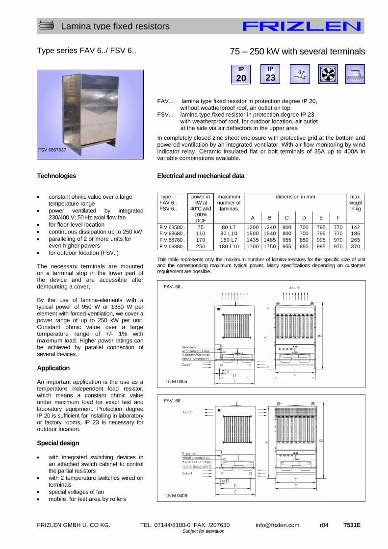
FRIZLEN GMBH U. CO KG. TEL: 07144/8100-0 FAX: /207630 [email protected] r04 T531E Subject for alteration
Lamina type fixed resistors
Type series FAV 6../ FSV 6.. Technologies constant ohmic value over a large
temperature range power ventilated by integrated
230/400 V; 50 Hz axial flow fan for floor-level location continuous dissipation up to 250 kW paralleling of 2 or more units for
even higher powers for outdoor location (FSV..) The necessary terminals are mounted on a terminal strip in the lower part of the device and are accessible after demounting a cover, By the use of lamina-elements with a typical power of 950 W or 1380 W per element with forced-ventilation, we cover a power range of up to 250 kW per unit. Constant ohmic value over a large temperature range of +/- 1% with maximum load. Higher power ratings can be achieved by parallel connection of several devices. Application An important application is the use as a temperature independent load resistor, which means a constant ohmic value under maximum load for exact test and laboratory equipment. Protection degree IP 20 is sufficient for installing in laboratory or factory rooms, IP 23 is necessary for outdoor location. Special design with integrated switching devices in
an attached switch cabinet to control the partial resistors
with 2 temperature switches wired on terminals
special voltages of fan mobile, for test area by rollers
75 – 250 kW with several terminals FAV... lamina type fixed resistor in protection degree IP 20,
without weatherproof roof, air outlet on top FSV... lamina type fixed resistor in protection degree IP 23,
with weatherproof roof, for outdoor location, air outlet at the side via air deflectors in the upper area
In completely closed zinc sheet enclosure with protective grid at the bottom and powered ventilation by an integrated ventilator. With air flow monitoring by wind indicator relay. Ceramic insulated flat or bolt terminals of 35A up to 400A in variable combinations available.
Electrical and mechanical data
dimension in mm max. weight in kg
Type FAV 6.. FSV 6..
power in kW at
40°C and 100% DCF
maximum number of laminas
A B C D E F
F.V 68580.. 75 80 L7 1200 1240 800 700 795 770 142F.V 68680.. 110 80 L10 1500 1540 800 700 795 770 185 F.V 68780.. 170 180 L7 1435 1485 955 850 995 970 265 F.V 68880.. 250 180 L10 1700 1750 955 850 995 970 370
This table represents only the maximum number of lamina-resistors for the specific size of unit and the corresponding maximum typical power. Many specifications depending on customer requirement are possible.
FSV 6867637
IP
23 IP
20
FAV..68..
15 M 0365
FSV..68..
15 M 0409

www.fr iz len.com
t100
t200
t300
t400
t500
t600
t 6 0 0 – d i e r o b u s t e N / t h e r o b u s t o N e s
stahlgitterfestwiderstände0,5 bis 250 Kilowatt
Stahlgitterfestwiderstände als Einzelelemente, die einbaufähig sind
und daraus aufgebaute Stahlgitterfestwiderstandsgeräte in ver-
schiedenen Schutz- und Befestigungsarten.
Mit und ohne Abdeckung mit Anschluss am Widerstand oder an
Klemmen in Schutzart IP00, IP20 oder IP23
Für Wand- oder Bodenmontage oder für Kanaleinbau
Thermisches Überstromrelais, Temperaturschalter oder FRIZLEN
DC-Powerswitch für thermische Überwachung und Abschaltung
Fremdbelüftet für große Leistungen, Parallelschaltung von Geräten
für Leistungen größer 250 kW
steel-grid fi xed resistors0,5 up to 250 Kilowatt
Steel-grid fi xed resistors as individual components, that can be
integrated into other units and composed to steel-grid fi xed resistor
units in different degrees of protection and mounting types.
With or without cover, connection direct to the resistor
or on terminals in degree of protection IP00, IP20 or IP23
For horizontal and vertical mounting and for integration into
exhaust air installations
Thermal overload relay, temperature switch or FRIZLEN
DC-Powerswitch for thermal monitoring and switch off
Forced ventilation for higher dissipation, switching in parallel
of units for dissipation > 250 kW

FRIZLEN GMBH U. CO KG. TEL: 07144/8100-0 FAX: /207630 [email protected] r04 T611E Subject for alteration
Steel-grid fixed resistors
Contents
Properties
Applications
This list comprises steel-grid fixed resistors as individual components in the production series S, as well as resistor blocks in the series FE and FK.. that can be integrated into other units and composed to steel-grid fixed units in different degrees of protection and mounting types maximum characteristics type series page typical power general survey T612E
technical details T613E
0,5 kW suitable for integration, individual elements S 1 – S 30 T621E
22 kW suitable for integration, with threaded bolt M12 FE 31.. T622E
22 kW suitable for integration, with flat side-plates FKE 31.. T623E
22 kW flat construction form, 2 terminals, various types FGF.. 31.. T624E
12 kW for switch cabinet, 2 terminals FGHD.. 31.. T626E
66 kW for integration with great rated power FK 3.. T627E
250 kW in canal construction FKK 3.. T628E
66 kW for floor mounting, also IP 23 FA 3../FS 3.. T629E
5,0 kW for wall mounting, IP 23 FS 319.. / 320.. T630E
250 kW various wattage rating, with forced ventilation FSV 3.. / FAV 3.. T631E
0,5 kW suitable for integration, individual 3 mm elements S301G – S321G T632E very favourable price-performance-ratio high power, high quality and low budget
individual components in 30 different resistor element values high ampacity up to 122 A per steel-grid fixed resistor, may be enlarged by
switching in parallel
lower temperature coefficient than cast iron resistors therefore smaller dependence of the resistor value on temperature than cast iron
resistors
high heat capacity overload resistant at short time load
very robust construction insensitive to vibrations
enclosures made from hot galvanised steel sheet various protection and mounting types (all series besides S and FE)
temperature switch available integrated warning for temperature monitoring (optional with many series)
thermal overload relay available integrated warning for high operating security (serialized with series FGFT)
intrinsically safe
to switch off the resistor safely by FRIZLEN DC POWERSWITCH (type series FGFX)
UL-recognition for American and Canadian market (E212934) on request for all marked series available
braking resistors for frequency converters and DC drives as well as railway applications
load resistors for emergency units, generators, motors and electronic power sources
starting resistors for DC motors
stator resistors for squirrel-cage motor
starting and regulating resistors for slip-ring rotor motor
discharge resistors for batteries
earthing resistors for low-voltage mains supplies

T612E r04 FRIZLEN GMBH U. CO KG. TEL: 07144/8100-0 FAX: /207630 [email protected] Subject for alteration
Steel-grid fixed resistors
Symbol
T 600 – Survey
type series characteristics
page
S1 - S30 a. S301G- S321G
621E 632E
FE.
31..
622E
FKE.
31..
623E
FGF..
31..
624E 625E
FGHD.
31..
626E
FK.
3..
627E
FKK.
3..
628E
FA./ FS. 3..
629E
FS 319..
- 320..
630E
F.V
3..
631E
power from [kW] 0,5 1,0 1,0 1,0 1,0 1,5 5,0 1,5 0,5 70
power up to [kW] 0,5 22 22 22 12 66 250 66 5,0 250
max. number of terminals (without temperature switch)
- - - 2 2 40 6 40 2 40
protection degree IP00 X X X X X
protection degree IP20 - if mounted on an appropriate surface
X X
protection degree IP20 X X
protection degree IP23 X X X
horizontal mounting X X
vertical mounting X X
horizontal mounting X X X X X
vertical mounting X X X X
temperature switch (optional) X X X X X X X X
thermal overload relay X
FRIZLEN DC-POWERSWITCH X
Anschluss an Fahnen am Widerstand
X X X
integration possible X X X X X
forced ventilation X
X X X X X X X
Rights for improvements and modifications of our products reserved. Modifications, errors and misprints justify no claim for damages.
We refer to our terms of sales and delivery.
IP
20
IP
00
IP
23
IP
20
E
with Recognition

FRIZLEN GMBH U. CO KG. TEL: 07144/8100-0 FAX: /207630 [email protected] r31 T613E Subject for alteration
Steel-grid fixed resistors
Technical details
Construction
Steel-grid fixed resistor elements
Type series S
Spectrum
Resistance values/ Production tolerance/
Temperature dependency
Energy absorption capacity/
Time constant
Resistor blocks Type series FE
Resistors Type series FK; FGF; FA; FS
Degrees of protection
Our steel-grid fixed resistor elements (SG) are made out of chromium alloyed and heat- resistant steel sheets of alloy X10CrAl13 (material # 1.4724), which has a high specific resistance value of 0,75 Ωxmm²/m. Both long sides of the SG are punched with slots in a meander-shaped current path. The ohmic value depends on the width of the straps. They are mechanically reinforced by strips of stainless steel with inlays of mica. By the use of SG with a big ohmic range of 0,022 to 5,6 and a typical power of 500 W per steel-grid we can achieve a wide range of resistance and power values by variation of steel-grid number and ohmic value. Steel-grid fixed resistor elements have a smaller dependence of the resistance value on the steel-grid temperature than cast iron resistors, however a noticeably higher one than wire-wound resistors. The resistance value increases approx. +15% between cold and operating temperature. The given rated resistance values of each individual SG in the table on page T621E are about 8% higher than the resistance value in cold condition and about 7% below the resistance value at the operating temperature. The production tolerance is 10%.
The energy absorption capacity varies per SG at a temperature increase of 300 K in dependancy of the ohmic value between 50 and 70 kWs.
The average thermal time constant is 100 s. If larger power ratings are to be obtained, several SG are assembled by M12-thru bolts and isolating mica tubes to a resistance block. The isolation between 2 neighbouring SG is effected by glazed ceramic rolls, the current conduction by stainless steel rolls. The resistance block is prestressed by cup springs and so held under constant contact pressure. In addition to that individually screwed conductor rolls between two neighbouring SG are possible. A resistor block may consist of identical SG or of different SG with lugs as taps. In order to facilitate the integration, and/or to provide different degrees of protection, various kinds of enclosures are used. The enclosures are manufactured out of hot-galvanized and perforated steel sheet and therefore are well protected against corrosion. Also an extra varnish in RAL 7032 is available with an additional charge as well as enclosures in stainless steel (alloy 1.4301/AISI 304). Correlation of type series and degrees of protection according to EN 60529 and/or DIN VDE 0470 part 1 Type series
Degree of protection
First digit degree of protection against access & solid foreign objects
Second digit degree of protection against water
S FE FK..
IP 00 Non-protected – i.e. depending upon integration the user must provide a protection
Non-protected
FGF.. IP 20
Protected against access to hazardous parts with a finger and against solid foreign objects of 12,5mm and greater.
Non-protected
FA.. FAV..
IP 20
Non-protected
FS.. FSV..
IP 23 Protected against spraying water. Water sprayed at an angle up to 60° on either side of the vertical shall have no harmful effects. (for outdoor location)
if mounted on an appropriate surface – i.e. mounted on a surface according to degree of protection IP 20 or higher
IP
00
IP
20
IP
20
IP
23

T614E r04 FRIZLEN GMBH U. CO KG. TEL: 07144/8100-0 FAX: /207630 [email protected] Subject for alteration
Steel-grid fixed resistors
Protective measures
Air und creepage distances
UL-recognition
Excess current protection
Excess temperature protection
All our power resistors with degree of protection IP 20 or higher correspond to safety class system I, i.e. we provide connections for protective earth conductors according to EN 61140. Devices with degree of protection IP 20 or higher correspond to the CE low voltage directive. Power resistors being passive electronical or electrical units are not affected by the specific EMC standards. They do not produce any interfering radiations nor are they affected. Air and creepage distances are rated according to IEC 664 (DIN EN 0110 part 1) for the overvoltage category III and degree of pollution 3 for grounded three-phase mains supplies up to 3 x 500 V. Testing voltage 2.5 kV AC. These data are valid for all devices that are connected to mains voltage and derived voltages, as for example the intermediate circuit voltage of frequency converters. Do not conclude from the calculated relation between the rated power and the maximum producible ohmic value to the rated voltage! All important type series do have an UL- recognition both for the American and for the Canadian market. The devices were certified according to UL 508 under the number E212934. This recognition is the same as a recognition according to CSA C22.2 No.14. For further information please check the UL-flyer. (Please ask for it or visit us at www.frizlen.com) A protection of the resistors against overloading or excess temperature - as demanded in standards - can be realized with the help of a thermal overload relay provided by the user. The set current must correspond to the rated current of the resistor, that is calculated according to continuous duty power and resistance value corresponding to Ohm's law (formula: see "terminal details" p. T618E). Concerning the series FGFT the thermal overload relay is a component of the device - with exceeding of the rated current a signal contact is released. There will not be a disconnection of the resistor. Resetting by hand. Another kind of the excess temperature monitoring, particularly suited for long-term overloading, is the equipment with a temperature switch. In IP 20/23-resistor devices it is wired on terminals, in IP 00 resistors the switch is directly connectable and releases a signal contact, when the set temperature is exceeded. There will not be a disconnection of the resistor. See type series FEQ / FKEQ / FGF.Q / FKQ / FAQ / FSQ / F.VQ You can inform yourselfs about function and restrictions by our data sheet „Tripping of monitoring devices“. We can send it to you on request.
RES
RB1 RB2 T2 T1
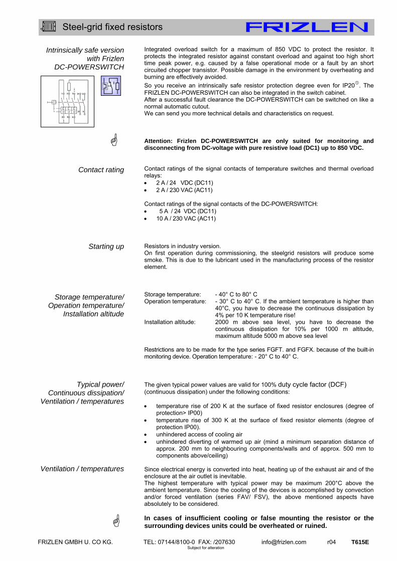
FRIZLEN GMBH U. CO KG. TEL: 07144/8100-0 FAX: /207630 [email protected] r04 T615E Subject for alteration
Steel-grid fixed resistors
Intrinsically safe version with Frizlen
DC-POWERSWITCH
Contact rating
Starting up
Storage temperature/ Operation temperature/
Installation altitude
Typical power/ Continuous dissipation/
Ventilation / temperatures
Ventilation / temperatures
Integrated overload switch for a maximum of 850 VDC to protect the resistor. It protects the integrated resistor against constant overload and against too high short time peak power, e.g. caused by a false operational mode or a fault by an short circuited chopper transistor. Possible damage in the environment by overheating and burning are effectively avoided.
So you receive an intrinsically safe resistor protection degree even for IP20. The FRIZLEN DC-POWERSWITCH can also be integrated in the switch cabinet. After a successful fault clearance the DC-POWERSWITCH can be switched on like a normal automatic cutout. We can send you more technical details and characteristics on request. Attention: Frizlen DC-POWERSWITCH are only suited for monitoring and disconnecting from DC-voltage with pure resistive load (DC1) up to 850 VDC. Contact ratings of the signal contacts of temperature switches and thermal overload relays: 2 A / 24 VDC (DC11) 2 A / 230 VAC (AC11) Contact ratings of the signal contacts of the DC-POWERSWITCH: 5 A / 24 VDC (DC11) 10 A / 230 VAC (AC11) Resistors in industry version. On first operation during commissioning, the steelgrid resistors will produce some smoke. This is due to the lubricant used in the manufacturing process of the resistor element. Storage temperature: - 40° C to 80° C Operation temperature: - 30° C to 40° C. If the ambient temperature is higher than
40°C, you have to decrease the continuous dissipation by 4% per 10 K temperature rise!
Installation altitude: 2000 m above sea level, you have to decrease the continuous dissipation for 10% per 1000 m altitude, maximum altitude 5000 m above sea level
Restrictions are to be made for the type series FGFT. and FGFX. because of the built-in monitoring device. Operation temperature: - 20° C to 40° C. The given typical power values are valid for 100% duty cycle factor (DCF) (continuous dissipation) under the following conditions: temperature rise of 200 K at the surface of fixed resistor enclosures (degree of
protection> IP00) temperature rise of 300 K at the surface of fixed resistor elements (degree of
protection IP00). unhindered access of cooling air unhindered diverting of warmed up air (mind a minimum separation distance of
approx. 200 mm to neighbouring components/walls and of approx. 500 mm to components above/ceiling)
Since electrical energy is converted into heat, heating up of the exhaust air and of the enclosure at the air outlet is inevitable. The highest temperature with typical power may be maximum 200°C above the ambient temperature. Since the cooling of the devices is accomplished by convection and/or forced ventilation (series FAV/ FSV), the above mentioned aspects have absolutely to be considered. In cases of insufficient cooling or false mounting the resistor or the surrounding devices units could be overheated or ruined.
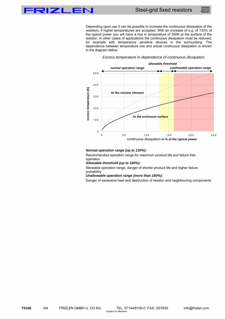
T616E r04 FRIZLEN GMBH U. CO KG. TEL: 07144/8100-0 FAX: /207630 [email protected] Subject for alteration
Steel-grid fixed resistors
Depending upon use it can be possible to increase the continuous dissipation of the resistors, if higher temperatures are accepted. With an increase of e.g. of 130% of the typical power you will have a rise in temperature of 350K at the surface of the resistor. In other cases of applications the continuous dissipation must be reduced, for example with temperature sensitive devices in the surrounding. The dependence between temperature rise and actual continuous dissipation is shown in the diagram below.
Normal operation range (up to 130%):
Recommended operation range for maximum product life and failure free operation Allowable threshold (up to 160%):
Allowable operation range, danger of shorter product life and higher failure probability Unallowable operation range (more than 160%):
Danger of excessive heat and destruction of resistor and neighbouring components
Excess temperature in dependence of continuous dissipation
0
1 0 0
2 0 0
3 0 0
4 0 0
5 0 0
0 5 0 1 0 0 1 5 0 2 0 0 2 5 0
D a u e r le is tu n g in % d e r T y p le is tu n g
Üb
erte
mp
erat
ur
[K]
normal operation range
allowable threshold unallowable operation range
At the resistor element
continuous dissipation in % of the typical power
exce
ss t
em
per
atu
re [
K]
At the enclosure surface

FRIZLEN GMBH U. CO KG. TEL: 07144/8100-0 FAX: /207630 [email protected] r04 T617E Subject for alteration
Steel-grid fixed resistors
Short time dissipation/ Total cycle time/
Duty cycle factor(DCF)
Overload factor(OLF)
Calculation example given:
wanted: continuous dissipation
At many applications resistors are not loaded in continuous but in short time operation. In the following you will find indications, how to calculate the allowable short time dissipation with the help of the duty cycle factor (DCF) and the overload factor (OLF). If the DCF factor is not known, it can be calculated as follows:
Warning: The total cycle time may be maximum 120 s - shorter total cycle times are possible. The total cycle times for motors are mostly higher than 120 s
By comparison of the known DCF-factor with the following diagram or table you can work out the overload factor (OLF) and/or the continuous and the short time dissipation. DCF 1% 3 % 6% 15% 25% 40% 60% 80% 100% OLF 20 12 7,6 4,0 3,0 2,2 1,5 1,12 1,0
The continuous and the short time dissipation can be calculated as follows:
Resistor with a short time dissipation of 100 kW for 48 s and a total cycle time of 120s
The duty cycle factor (DCF) is 48 s : 120 s x 100% = 40% Overload factor (OLF) for 40% DCF, according to table it is 2,2 The continuous dissipation is 100 kW : 2,2 = 45,5 kW; You need a resistor with a continuous dissipation of at least 45,5 kW!
Total cycle time = 120 s
ton = 48 s
Total cycle time = 30 s
ton = 7,5 s
%404,0120
481
s
sDCF %2525,0
30
5,72
s
sDCF
OLFndissipatioContinuousndissipatiotimeShort
OLFfactorOverload
ndissipatiotimeShortndissipatioContinuous
timecycleTotal
ttimeonSwitchDCFfactorcycleDuty on)(
Overload factor (OLF) in dependence of duty cycle factor (DCF)(Total cycle time = 120s)
DCF
OLF
- o
f ste
elgr
id r
esis
tors
1% 6% 10% 20% 40% 60% 100%
20
10
3
1

T618E r04 FRIZLEN GMBH U. CO KG. TEL: 07144/8100-0 FAX: /207630 [email protected] Subject for alteration
Steel-grid fixed resistors
Terminal details/ Monitoring devices/
Cross section
Wiring
Mounting
Rated current and cross section of terminals and monitoring types. Type abbreviation rated
current in A with 100%
DCF
rated current in A with 40%
DCF
maximum cross section
porcelain terminal
PK 16 up to 2,5 mm²
ceramic flat terminal
FK 35 44 2,5 - 10 mm²
G 5 30 38 0,5 – 2,5 (4) mm²
AWG 24 - 12 device terminal out of Polyamid (PA) G 10 60 75
0,5 – 10 (16) mm² AWG 20 - 6
BK M6 60 75 BK M8 115 143 BK M10 220 287
bolt terminals out of ceramic
BK M12 400 536
cross section depending on lug size with
corresponding hole
HDFK4 30 38 up to 4,0 mm²; AWG 24 -
12 feed-through terminal out of PA HDFK10-HV 65 82 up to 10 mm²; AWG 20 - 6
ST2,5 20 25 up to 2,5 mm²; AWG 26 -
12 cage clamp terminal out of PA
ST 4 30 38 up to 4,0 mm²; AWG 20 –
10
signal contact 2 - up to 2,5 mm²; AWG 16-
12 thermal overload relay main
connection bis 13/24/80 17/30/100 2,5/4/25 mm²; AWG 20 - 6
signal contact 10 - up to 1,5 (2,5) mm²; AWG
16 - 12 DC-POWER-SWITCH FPS main
connection 40 50 up to 16 mm²; AWG 4
The values in the brackets are valid for solid conductor or single-wired. The rated current is calculated in each case due to the Ohm`s law as follows:
whereas P is the power of the resistor and R ist he value of the resistance
If terminals are required, the connections are wired by means of flexible, heat resistant, silicone-insulated wire on a terminal strip that is located in the lower and/or front part of the equipment within the area of the entering cooling air. If the wiring is accomplished by the user, make sure that a heat resistant wire is used. For the UL-versions we use wires with UL-admission (other wire-isolations on request). For the type series FK /FA /FS 3.. and for F.V 38.. there is an undrilled cable entry strip in the lower part. It can be provided by the user with appropriate drillings for cable glands as strain relief. Please mind the mounting indications in the corresponding type series! You will find these icons in the data sheets: Allowable: On horizontal surfaces Allowable: On vertical surfaces terminals at the bottom Not allowable: On vertical/horizontal surfaces terminals at the top, left or right Allowable: On vertical surfaces
R
PI

FRIZLEN GMBH U. CO KG. TEL: 07144/8100-0 FAX: /207630 [email protected] r04 T619E Subject for alteration
Steel-grid fixed resistors
Selection of Type series and
dimension
Type code 1
Type code 2
Selection of devices/ Example
given:
wanted: resistor
The tables on the following data sheets contain a selection of the available equipment assemblies and/or the appropriate maximum assembly of the respective size of the device. Less steel-grids (SG) are possible. For all type series, except for S, the following type codes are shown to explain the complete type designations. FK E U 3 1 3 30 02 - 50 ohmic value 10% number of terminals or connecting lugs # of steel-grids (e.g.: 30 SG = 15 kW) construction width 1; 2; 3; 4, 5,
construction height 1; 2 or 3 tiers (with FGF.., FKE., FE. only height 1!)
type series 3 UL-construction
addition like E(Q); FG; FK(Q); FL(Q); HD(Q) u. FT - Q stands for temperature-switch(TS)
type series FK; FE; FG; FA or FS FS 3 20 09 02 - 22 ohmic value 10% number of terminals or connecting lugs # of steelgrids (e.g.: 9 SG = 4,5 kW)
type series 19; 20; 85; 86; 87; 88
type series 3 addition like V (only for 85 – 88) type series FA or FS Type series S represents individual components. You can see their complete type designation in the table on p. T621E. Devices that are built according to UL standard are marked additionally with "U" at the last position in the sequence of letters- see type code 1 and the following example continuous power rating of the resistor: P = 9,0 kW resistance value: R = 27 continuous current of the resistor: I = 18 A construction with terminals that are protected against contact degree of protection IP 20 (mounting on switch cabinet) with temperature switch (TS) design according to UL number of SG = continuous power rating : power per SG = 9,0 kW : 0,5 kW = 18 SG selection of type series taken from survey on p. T612E possible type series: FGF..; FA with mounting on a switch cabinet – means on a surface of degree of protection
IP 20 you can choose the smaller and low priced alternative FGF, compared to type series FA. If the terminals should be in an attached terminal box, type series FGFKQ is adequate, because of the necessary temperature switch (TS)
with 18 SG you can select within enclosure size construction height 1 and width 2 (max. poss. 24 SG)
construction according to UL508: add “U“ to the type designation, complete type designation is FGFKQU 3121802 – 27
(with 2 device terminals up to 65 A). Type description see p. T624Eff

T620E r04 FRIZLEN GMBH U. CO KG. TEL: 07144/8100-0 FAX: /207630 [email protected] Subject for alteration
Steel-grid fixed resistors
kWV
R
UP 9,16
25
650 22
wantedcold RR 95,0
Dimensioning example
given:
wanted:
selection of steel-grids:
selection of products:
Dimensioning example
given:
wanted:
selection of steel-grids:
selection of products:
Braking resistor
Maximum intermediate circuit voltage 650V : UZK = 650 V Smallest allowable resistance value:
(from data sheet of frequency converter) Rmin = 25
maximum allowable chopper current duty cycle factor for braking operation (corresponding to
the application), for a hoist drive e.g. 40 % DCF referring to a total cycle time of 120 s
DCF = 40% degree of protection IP 20 in fixed condition short time dissipation of the resistor with 40%DCF continuous dissipation = short time dissipation :
overload factor (s. p. T616E) continuous dissipation = 16,9 kW : 2,2 = 8,5 kW number of steel-grids = continuous dissipation : dissipation per SG number of steel-grids = 8,5 kW : 0,5 kW 17 SG resistance value of a SG = Rmin : SG-number = 25 : 17 = 1,62
The ohmic value should not be smaller than Rmin altogether, since otherwise the allowable chopper current is exceeded! SG selection of p. T621E = 10 pieces S 23 – 1,5 and 7 pieces S24 – 1.8 total ohmic value is 27,6
With degree of protection IP 20 in fixed condition – series FGF.. With 17 steel-grids – construction size 312 17.. with 2 terminals up to 35 A, without temperature switch – type FGFG
The complete type designation is FGFG 3121702 – 27.6 (s.p. T624Eff) Load resistor Rated voltage U of supply unit: U = 3 x 230/400 V rated dissipation: P = 15 kW duty cycle factor: DCF = 100% star connection, star point in the unit degree of protection IP 23 rated current per phase with star connection: nominal value of resistance per phase with star connection:
value of resistance in cold condition:
If the demanded rated dissipation is to be achieved at operating temperature in the range of the resistance tolerance, it is advisable to consider the value of resistance in cold condition.
Then you can make your selection of steel grid.
Selection of steel-grids of p. T620E by the rated current of 21,7 A: S 21 – 1,0 number of SG per phase = value of resist. in cold condition: ohmic value per SG number of SG = 10,2 : 1,0 10 SG per phase – 3phases is 30 S 21 – 1 value of resistance in cold condition is therefore 3 x 10 resulting rated dissipation: 3 x 10 SG per 0,5 kW = 15 kW with degree of protection IP 23 – series FS.. with 30 steel-grid fixed resistors – size 313 30.. or 322 30..
(size 313.. is lower, size 322.. is narrower) with 3 terminals (star point in the unit) number of terminals ...03
with 4 terminals (star point wired on 1 terminal) number of terminals ...04 The complete type designation is FS 313 30 03 – 3 x 10,7
(low unit, star point in the unit) (type series FS s. p. T629E)
AV
R
UI ZK 26
25
650
min
7,213
400
3 A
V
I
UR
N
Nwanted
AV
kW
U
PI
N
NN 7,21
4003
15
3
7,1095,095,0 wantedcold RR

FRIZLEN GMBH U. CO KG. TEL: 07144/8100-0 FAX: /207630 [email protected] r04 T621E Subject for alteration
Steel-grid fixed resistors
Steel-grid fixed resistor elements S 1 – S 30 Technologies particularly flat design overload resistant
continuous dissipation 500 W energy absorption capacity with
T = 300 K, from 50 up to 70 kWs integration possible As accessories we deliver 1 or 2 lugs to each resistor element with connection screws M10 (S 1 - S 10) or M6 (S 11 - S 30). Normally they are not fixed, we will fix them upon request. We produce steel-grid fixed resistor elements in a wide range of resistance values of 0,022 up to 5,6 and a typical
power of 500 W per grid.
The given nominal ohmic values are about 8% above the value of cold condition and 7% below the value of operating temperature. The production tolerance is ±10%. We achieve a wide range of resistance values and wattage rating by variation of number of steel-grids and resistance values. Please consider the different designs and construction forms of the following series. The indicated ratings are valid for an ambient temperature of max. 40° C at sufficient ventilation. The indicated values for the duty cycle factor (%DCF) are preferred values and refer to a maximum total cycle time of 120 s. You will find further indications for dimensioning of a resistor for short time dissipation in chapter Technical Details pages T613E to T620E.
500 W for integration Steel-grid fixed resistor element, degree of protection IP 00, for integration into units. Connection at the resistor Electrical and mechanical data % DCF 100 60 40 25 15 6
typical power [W] 500 750 1100 1500 2000 3800
type Max. current in amp. with 40°C UT and sufficient
ventilation
recomm. connection screws...
S 1 – 0,022 0,022 122 150 183 211 250 344 M10S 2 – 0,027 0,027 122 150 183 211 250 344 M10 S 3 – 0,033 0,033 122 150 183 211 250 344 M10 S 4 – 0,039 0,039 112 138 168 194 230 315 M10 S 5 – 0,047 0,047 102 126 153 177 210 287 M10 S 6 – 0,056 0,056 94 115 140 163 193 265 M10 S 7 – 0,068 0,068 85 105 127 147 174 240 M10 S 8 – 0,082 0,082 77 96 115 133 158 217 M10 S 9 – 0,10 0,10 70 87 105 121 144 197 M10 S 10 – 0,12 0,12 64 79 96 111 131 180 M10 S 11 – 0,15 0,15 57 71 85 99 117 160 M6 S 12 – 0,18 0,18 52 65 78 90 107 146 M6 S 13 – 0,22 0,22 47 58 71 81 96 132 M6 S 14 – 0,27 0,27 42 53 63 73 86 118 M6 S 15 – 0,33 0,33 38 48 58 68 79 108 M6 S 16 – 0,39 0,39 35 44 53 62 73 100 M6 S 17 – 0,47 0,47 32 40 48 55 65 90 M6 S 18 – 0,56 0,56 29 37 44 51 60 83 M6 S 19 – 0,68 0,68 27 33 41 47 55 76 M6 S 20 – 0,82 0,82 24 30 36 42 49 67 M6 S 21 – 1,0 1,0 22 27 33 38 45 62 M6 S 22 – 1,2 1,2 20 25 30 35 41 56 M6 S 23 – 1,5 1,5 18 22,5 27 31 37 51 M6 S 24 – 1,8 1,8 16,5 20,5 25 28 34 46 M6 S 25 – 2,2 2,2 15 18,5 23 26 31 42 M6 S 26 – 2,7 2,7 13,5 16,5 20 23 27 37 M6 S 27 – 3,3 3,3 12 15 18 21 25 34 M6 S 28 – 3,9 3,9 11 14 16 19 23 31 M6 S 29 – 4,7 4,7 10 12,5 15 18 21 28 M6 S 30 – 5,6 5,6 9,3 11,3 13,7 16 18,6 25 M6
only valid for S3 – S30
S1 – S30
without connecting lugs with 2 mounted connecting lugs 16 M 0089
S14 – 0,27 with additional connecting lug
IP
00
E

T622E r04 FRIZLEN GMBH U. CO KG. TEL: 07144/8100-0 FAX: /207630 [email protected] Subject for alteration
Steel-grid fixed resistors
Type series FE 31.. Technologies for smaller up to middle power rating integration and combinations possible for mounting into switch cabinet,
resistor unit or ventilation duct continuous power rating up to 22 kW optional with temperature switch
(TS), with fast-on connectors 6,3x0,8; type designation would be FEQ 31...
Each resistor block can be equipped with 2 or more connecting lugs Depending on the current the connection is realized by M6 or M10 screw. The mounting into the switch cabinet, resistor unit or ventilation duct is made by M12 thread bolts. By means of series connection of steel-grid elements we achieve higher ohmic values; by connecting in parallel of several resistor blocks we achieve higher currents and power ratings. We can also mount several partial resistors into one resistor block (e.g. 3 phases), separated by insulation rolls. Warning: Not more than 3 resistor blocks should be mounted on top of each other! For customer wiring you should use a heat resistant wire.
Application An important application is the use as load resistor , where high power rating is demanded by the user. Further applications are e.g. the mounting of the steel-grid blocks into a ventilation duct with simultaneous forced ventilation by the exhaust air of a diesel engine radiator.
1,0 – 22 kW for integration Steel-grid fixed resistor block, degree of protection IP 00 for integration into switch cabinets, units or ventilation ducts. Connection directly at the resistor.
optional, type designation would be FE.U 31..
Electrical and mechanical data
production range
value
dimensions in mm
max. weight in kg
type FE 3.. without , FEQ 3.. with TS
typical power in kW at 40°C and 100%DCF from to
number of steel-grids corresp. to
given device size L
FE. 31503.. 1,5 0,07 16 3 180 3,5FE. 31504.. 2,0 0,09 22 4 180 4,0 FE. 31005.. 2,5 0,11 28 5 280 5,0 FE. 31007.. 3,5 0,15 39 7 280 6,0 FE. 31009.. 4,5 0,20 50 9 280 7,0 FE. 31112.. 6,0 0,26 67 12 380 8,0 FE. 31114.. 7,0 0,31 78 14 380 9,0 FE. 31216.. 8,0 0,35 89 16 580 11,0 FE. 31220.. 10,0 0,44 112 20 580 13,0 FE. 31224.. 12,0 0,53 134 24 580 15,0 FE. 31326.. 13,0 0,57 145 26 780 17,5 FE. 31330.. 15,0 0,66 168 30 780 19,5 FE. 31334.. 17,0 0,75 190 34 780 21,5 FE. 31436.. 18,0 0,79 201 36 980 23,5 FE. 31440.. 20,0 0,88 224 40 980 25,5 FE. 31444.. 22,0 0,97 246 44 980 27,5
This table represents only a selection of our program. All numbers of steel-grids between 2 pc. (1,0 kW) und 44 pc. (22 kW) corresponding to our types are available. Type code and selection of units see Technical Details pages T613E to T620E. FE 31.. 16 M 0052
Example of dimensioning and selection of a special unit:
One phase load resistor: 5,0 kW for 48 V DC; resistance value 0,46 ; selected: 9 S5 –0,047 +1 S4-0,039 = 0,46 ; type FE 3111002 – 0,46 with typical power 5,0kW, connection on 2 connection lugs M10 at the resistor, with temperature switch (2 connections)
FEQ 311 10 04 - 0,46 ohmic value 10% number of connection lugs (02) + 02 für TS number of steel-grids type series (with TS)
FE 3111002 with 2 connecting lugs
IP
00
E
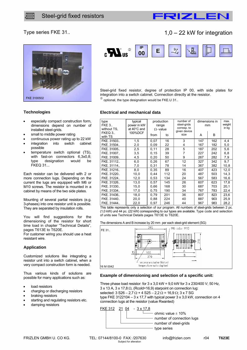
FRIZLEN GMBH U. CO KG. TEL: 07144/8100-0 FAX: /207630 [email protected] r04 T623E Subject for alteration
Steel-grid fixed resistors
Type series FKE 31.. Technologies especially compact construction form,
dimensions depend on number of installed steel-grids.
small to middle power rating continuous power rating up to 22 kW integration into switch cabinet
possible temperature switch optional (TS),
with fast-on connectors 6,3x0,8; type designation would be FKEQ 31...
Each resistor can be delivered with 2 or more connection lugs. Depending on the current the lugs are equipped with M6 or M10 screws. The resistor is mounted in a cabinet by means of the two side plates. Mounting of several partial resistors (e.g. 3-phases) into one resistor unit is possible. They are separated by insulation rolls. You will find suggestions for the dimensioning of the resistor for short time load in chapter “Technical Details”, pages T613E to T620E. For customer wiring you should use a heat resistant wire. Application Customized solutions like integrating a resistor unit into a switch cabinet, when a very compact construction form is needed. Thus various kinds of solutions are possible for many applications such as: load resistors charging or discharging resistors braking resistors starting and regulating resistors etc. damping resistors
1,0 – 22 kW for integration Steel-grid fixed resistor, degree of protection IP 00, with side plates for integration into a switch cabinet. Connection directly at the resistor.
optional, the type designation would be FKE.U 31..
Electrical and mechanical data
production range
value
dimensions in mm
max. weight in kg
type FKE 3.. without TS, FKEQ 3.. with TS
typical power in kW at 40°C and 100%DCF
from to
number of steel-grids corresp. to
given device size A B
FKE. 31503.. 1,5 0,07 16 3 147 162 4,4FKE. 31504.. 2,0 0,09 22 4 167 182 5,0 FKE. 31005.. 2,5 0,11 28 5 187 202 5,6 FKE. 31007.. 3,5 0,15 39 7 227 242 6,8 FKE. 31009.. 4,5 0,20 50 9 267 282 7,9 FKE. 31112.. 6,0 0,26 67 12 327 342 9,7 FKE. 31114.. 7,0 0,31 78 14 367 382 10,8 FKE. 31216.. 8,0 0,35 89 16 407 423 12,0 FKE. 31220.. 10,0 0,44 112 20 487 503 14,3 FKE. 31224.. 12,0 0,53 134 24 567 583 16,6 FKE. 31326.. 13,0 0,57 145 26 607 623 17,8 FKE. 31330.. 15,0 0,66 168 30 687 703 20,1 FKE. 31334.. 17,0 0,75 190 34 767 783 22,4 FKE. 31436.. 18,0 0,79 201 36 807 823 23,6 FKE. 31440.. 20,0 0,88 224 40 887 903 25,9 FKE. 31444.. 22,0 0,97 246 44 967 983 28,2
This table represents only a selection of our program. All numbers of steel-grids between 2 pc. (1,0 kW) und 44 pc. (22 kW) corresponding to our types are available. Type code and selection of units see Technical Details pages T613E to T620E. The dimensions A and B increase by 20 mm per each steel-grid element (SG) FE 31..
16 M 0042
Example of dimensioning and selection of a specific unit:
Three phase load resistor: for 3 x 3,0 kW = 9,0 kW for 3 x 230/400 V; 50 Hz, 3 x 13 A, 3 x 17,8 , (Rcold=16,9) starpoint on connection lug: selected: 3 S26 – 2,7 + 4 S25 – 2,2 = 16,9 ; 3 x 7 SG type FKE 3122104 – 3 x 17,7 with typical power 3 x 3,0 kW, connection on 4 connection lugs at the resistor (value Rwanted)
FKE 312 21 04 - 3 x 17,8 ohmic value 10% number of connection lugs number of steel-grids type series
FKE 3100502
16 00 2
IP
00 E

T624E r04 FRIZLEN GMBH U. CO KG. TEL: 07144/8100-0 FAX: /207630 [email protected] Subject for alteration
Steel-grid fixed resistors
Type series FGF.. 31.. Technologies low priced type, very compact design continuous power rating up to 22 kW for mounting on top of a switch
cabinet (all types besides FGFD..) for integration into a switch cabinet
with terminals that are protected against contact (type FGFD..)
units may be wall or plate mounted, perforated steel sheet at the front, top and bottom, terminals at the bottom.
terminal type and size selectable according to mounting place and connection technics
optional with temperature switch (type FGF.Q)
optional with thermal overload relay (type FGFT)
optional in intrinsically safe version with FRIZLEN DC-POWERSWITCH (type FGFX)
Application These units are fitting especially for mounting on, beside or in a switch cabinet by their relatively flat and compact construction in 6 widths with various connections and monitoring possibilities (Please mind the description of the types). An important application is the use as braking resistor for motor/generator drive of motors with frequency converters, where high power rating is combined with low budget solution. You will find suggestions for the dimensioning of the resistor for short time load at chapter Technical Details, pages T613E to T620E. Warning When resistor is integrated into a cabinet we recommend to provide a corresponding forced ventilation by the user for better removal of larger dissipations.
1,0 – 22 kW with 2 terminals Steel-grid fixed resistor unit, degree of protection IP 20 if mounted on an appropriate surface, with zinc plated steel enclosure. It is equipped with max. 2 terminals of different kinds mounted in or at the enclosure or in the attached terminal box. Some types can be provided with a temperature switch or with an integrated thermal overload relay or DC/POWERSWITCH. For your selection of a specific type you will find tables on the next page.
if mounted on an appropriate surface
optional (not for FGFG and FGFX), type designation would be FGF..U 31..
Details of the different types Type FGFG: Version with 2 flat type terminals up to max. 35 A rated current in the attached terminal box with cable gland. An additional temperature switch is not possible. Type FGFK(Q): Version like FGFG, with a bigger attached terminal box with cable glands, the space is sufficient for 2 terminals up to M8 (max. 115 A rated current), and for 2 additional porcelain terminals for an optional temperature switch (FGFKQ). Type FGFL(Q): Version, where all terminals are mounted on the terminal strip inside the housing. Terminals up to M8 (max. 115 A rated current) are accessible after disassembling a part of the cover. If equipped with temperature switch, there are 2 additional porcelain terminals on the terminal strip (Type FGFLQ).No cable glands. Type FGFD(Q): Construction with feed-through terminals up to max. 65 A that are protected against contact and directly fixed on the side plate. It is a space-saving solution for integrating into a switch cabinet. If equipped with temperature switch there are 2 additional protected feed-through terminals (FGFDQ). Type FGFT: Version with integrated thermal overload relay in the attached terminal box with cable glands up to max. 80 A rated current. With integrated short-circuit and overload signalling. Connection directly at the overload relay. Type FGFX: Intrinsically safe version with integrated FRIZLEN DC-POWERSWITCH in the attached terminal box with cable glands, up to max. 40 A rated current. With integrated short-circuit and overload protection inclusive switching off the resistor and signalling. Connection directly at the FRIZLEN DC-POWERSWITCH.
DGBM Nr. 20 2009 015 851.9
Attention: Only for DC voltage up to 850 VDC. Rated current and cross section of terminals and devices
See technical details on page T618E.
FGFG 3122002
IP
20

FRIZLEN GMBH U. CO KG. TEL: 07144/8100-0 FAX: /207630 [email protected] r04 T625E Subject for alteration
Steel-grid fixed resistors
Monitoring options of the type series FGF.. 31..
1. Signalling – no disconnection! This warning has to be considered by the customer, e.g. by a warning or disconnection of the mains through the customer. Details, on page T615E. 1a) with temperature switch (FGF.Q)
Different types can be equipped for temperature monitoring with a temperature switch which monitors an overloading of the resistor by a normally closed contact free of potential (NCC).
Connections pls. look at picture 1a) 1b) with thermal overload relay (FGFT)
An eventual overload of the resistor is monitored by the thermal overload relay which is mounted in the attached terminal box. This is accomplished by NCC and NOC contacts. Also for signalling high short time peak power.
Connections pls. look at picture 1b)
Pic. 1a) P 1b)
2. Disconnecting and signalling!
with FRIZLEN DC-POWERSWITCH (FGFX) up to 850 VDC and up to 40 A
This type series with integrated overload switch in the attached terminal box is able to protect the integrated resistor from constant overload and from too high short time peak power, e.g. caused by a false operational mode or a fault by an short circuited chopper transistor. This option for protection not only signals the hardware default, it switches off the object / the resistor absolutely reliable! Possible damage in the environment by overheating and burning are effectively avoided. After a successful fault clearance the DC-POWERSWITCH can be switched on like a normal automatic cutout.
Connections pls. look at picture
1,0 – 22 kW with 2 terminals Decision matrix
type
properties
FGFG
FGFK
FGFKQ
FGFL
FGF LQ
FGFD
FGF DQ
FGFT
FGFX
with temperature switch (TS)
X X X
thermal overload relay (up to max. 80 A rated current)
X
DC-POWERSWITCH (up to max. 40 A) X
terminals in attached terminal box with PG- strain relief
X X X X X
terminals inside unit (without PG- strain relief)
X X
flat terminals up to max. 35 A
X X X X X
device terminal up to max. 60 A
X X
bolt terminals M6 up to max. 60 A
X X X X
bolt terminals M8 up to max. 115 A
X X X X
feed-thru terminals up to max. 65 A
X X
PA cage clamp terminals up to max. 30 A
X X
Electrical and mechanical data
production range
value
dimensions in mm types
FGFG, FGFK, FGFKQ, FGFL, FGFLQ, FGFD, FGFDQ, FGFT, FGFX
typical power in
kW at 40°C and
100% DCF
from to
number of steel-
grids corresp. to given device size
A B C1
C2
C3
max.weight
in kg
FGF.. 31503.. 1,5 0,07 16 3 170 195 207 230 255 6,0FGF.. 31504.. 2,0 0,09 22 4 170 195 207 230 255 6,5 FGF.. 31005.. 2,5 0,11 28 5 270 295 307 330 355 7,5 FGF.. 31007.. 3,5 0,15 39 7 270 295 307 330 355 8,5 FGF.. 31009.. 4,5 0,20 50 9 270 295 307 330 355 9,5 FGF.. 31112.. 6,0 0,26 67 12 370 395 407 430 455 12 FGF.. 31114.. 7,0 0,31 78 14 370 395 407 430 455 13 FGF.. 31216.. 8,0 0,35 89 16 570 595 607 630 655 18 FGF.. 31220.. 10,0 0,44 112 20 570 595 607 630 655 20 FGF.. 31224.. 12,0 0,53 134 24 570 595 607 630 655 22 FGF.. 31326.. 13,0 0,57 145 26 770 795 807 830 855 29 FGF.. 31330.. 15,0 0,66 168 30 770 795 807 830 855 31 FGF.. 31334.. 17,0 0,75 190 34 770 795 807 830 855 33 FGF.. 31436.. 18,0 0,79 201 36 970 995 1007 1030 1055 40 FGF.. 31440.. 20,0 0,88 224 40 970 995 1007 1030 1055 42 FGF.. 31444.. 22,0 0,97 246 44 970 995 1007 1030 1055 44
This table represents only a selection of our program. All numbers of steel-grids between 2 pc. (1,0 kW) und 44 pc. (22 kW) corresponding to our types are available. Type code and selection of units see Technical Details pages T613E to T620E. Example: 2 device terminals + temperature switch (2 terminals) => FGFKQ 31...04 dim. C1 is only valid for Type FGFD (dimension sheet 16M0442) dim. C2 is only valid for Type FGFG (dimension sheet 16M0041) dim. C3 valid for types FGFK (dim. sheet 16M0410), FGFT (dim. sheet 16M0086) and FGFX (dim. sheet 16M0841) for type FGFL dim. „B“ is valid, as design without term.box (dim. sheet 16M0424)
FGF.. 31.. C1, C2, C3
** only for types FGF.. 312.. FGF.. 313.. FGF.. 314..
RES
RB1 RB2 T2 T1

T626E r04 FRIZLEN GMBH U. CO KG. TEL: 07144/8100-0 FAX: /207630 [email protected] Subject for alteration
Steel-grid fixed resistors
Type series FGHD 31.. Technologies low priced type, very compact design for middle power ratings up to 12 kW for space saving integration into a
switch cabinet optional with temperature switch
wired on two terminals. Type designation would be FGHDQ. 31...
The given power rating values are valid for 100%CD (continuous dissipation). For short time operation you will find the values in the following table as a function of the duty cycle factor (DCF). Just multiply by the corresponding overload factor (OLF).
DCF 60% 40% 25% 15% 6%
OLF 1,5 2,2 3,0 4,0 7,6 These overload factors are valid for a total cycle time of maximum 120 s You will find further details in chapter Technical Details pages T613E to T620E. Application An important application is the use as braking resistor for motor/generator drive of motors with frequency converters, where middle power ratings are to be integrated into a switch cabinet in a space saving way. Warning The user has to make sure that large dissipations are removed. We recommend an adequate forced ventilation.
1,0 – 12 kW with 2 terminals, for integration into switch cabinet
Steel-grid fixed resistor, degree of protection IP 20 in fixed condition, in zinc plated steel sheet enclosure with 2 feed-through terminals for the resistor, that are integrated into the side-panel end plates, protected against contact according to BGV A2. Optional also with temperature switch (TS).
if mounted on an appropriate surface
optional, type designation would be FGHD.U 31.. Electrical and mechanical data
production range
value
dimensions in mm max. weight in kg
Type FGHD. 31.. without TS, FGHDQ. 31.. with TS
typical power in
kW at 40°C and
100% DCF from to
max. number of steel-grids corresp. to given device
size
A B
FGHD..31502.. 1,0 0,05 11 2 170 195 6,0FGHD..31503.. 1,5 0,07 16 3 170 195 6,5 FGHD..31504.. 2,0 0,09 22 4 170 195 7,0 FGHD..31005.. 2,5 0,11 28 5 270 295 7,5 FGHD..31007.. 3,5 0,15 39 7 270 295 8,5 FGHD..31009.. 4,5 0,20 50 9 270 295 9,5 FGHD..31112.. 6,0 0,26 67 12 370 395 12 FGHD..31114.. 7,0 0,31 78 14 370 395 13 FGHD..31216.. 8,0 0,35 89 16 570 595 18 FGHD..31220.. 10,0 0,44 112 20 570 595 20 FGHD..31224.. 12,0 0,53 134 24 570 595 22
This table represents only a selection of our programm. All numbers of steel-grids corresponding to our types between 2 pc. (1,0 kW) und 24 pc. (12 kW) are available. Type code and selection of units see Technical Details pages T613E to T620E.
Example of dimensioning and selection of a specific unit:
One phase braking resistor for frequency converter drive with temperature switch, short time dissipation 24 kW at 15% DCF, total cycle time shorter than 120 s, intermediate voltage circuit 650V; resistance value 18 ; calculating of continuous dissipation: 24 kW : 4,0 = 6,0 kW; chosen: FGHDQ 3111204 - 18
FGHDQ 311 12 04 - 18 ohmic value 10% no. of terminals(2) + 2 terminals for TS number of steel-grids type series
FGHDQ 3100604
FGHD.. 31..
** only for FGHD.. 312.. 16 M 0428
IP
20
E

FRIZLEN GMBH U. CO KG. TEL: 07144/8100-0 FAX: /207630 [email protected] r04 T627E Subject for alteration
Steel-grid fixed resistors
Type series FK 3.. Technologies for middle and high power ratings Up to 40 FK-terminals continuous dissipation up to 66 kW for floor-level mounting optional with temperatue switch
(TS), type designation would be then FKQ 3...
The necessary terminals are mounted on a terminal strip in the lower part of the device. You will find suggestions for the dimensioning of the resistor for short time load at chapter Technical Details, pages T613E to T620E. Application This construction is especially appropriate for big power ratings that are to be low in weight and in price. The same applies to the installation in closed electrotechnical rooms, where the degree of protection IP 00 is allowed. Special design dimensioning for forced ventilation
supplied by the user special construction forms for
integration into exhaust air ducts for engine radiators
Option with temperature switch wired on 2
terminals, type then FKQ...
1,5 – 66 kW with up to 40 terminals Steel-grid fixed resistor unit, degree of protection IP 00 with 2 side-panel end plates out of zinc plated steel sheet. Ceramic isolated flat or bolt terminals of 35 A up to 400 A in variable combinations available.
optional, type designation would be FK.U 3..
Electrical and mechanical data
production range
value
dimensions in mm max. weight in kg
Type FK 3.. without TS, FKQ. 3.. with TS
max. typical power in kW at 40°C and 100% DCF
from to
max. number of steel-grids corresp. to given type
size A B C
FK. 31114.. 7,0 0,31 78 14 370 395 460 19FK. 31224.. 12,0 0,53 134 24 570 595 460 26 FK. 31334.. 17,0 0,75 190 34 770 795 460 38 FK. 31444.. 22,0 0,97 246 44 970 995 460 45 FK. 32128.. 14,0 0,16 156 28 370 395 710 31 FK. 32248.. 24,0 0,27 268 48 570 595 710 46 FK. 32368.. 34,0 0,38 380 68 770 795 710 70 FK. 32488.. 44,0 0,49 492 88 970 995 710 80 FK. 33272.. 36,0 0,18 403 72 570 595 960 62 FK. 33302.. 51,0 0,25 570 102 770 795 960 87 FK. 33432.. 66,0 0,32 739 132 970 995 960 115
This table only represents the maximum number of steel-grids of the specific size of unit and the corresponding maximum typical power. All numbers of steel-grids corresponding to our types between 3 pc. (1,5 kW) und 132 pc. (66 kW) are available. Type code and selection of units see Technical Details pages T613E to T620E.
Max. number of terminals up to Type
FK 35A
BK M6 60A
BK M8 115A
BK M10 170A
BK M10 220A
BK M12 400A
FK. 3.1.. 16 10 8 7 7 7FK. 3.2.. 24 16 14 12 12 11 FK. 3.3.. 32 23 20 17 17 16 FK. 3.4.. 40 30 26 22 22 20
Example of dimensioning and selection of a specific unit:
see Technical Details pages T613E to T620E
FK..
16 M 0045
FK 3236309
IP
00 E

T628E r04 FRIZLEN GMBH U. CO KG. TEL: 07144/8100-0 FAX: /207630 [email protected] Subject for alteration
Steel-grid fixed resistors
Type series FKK.. 3.. Technologies for middle or high power ratings low priced solution for existing forced
ventilation provided by the customer continuous dissipation up to 250 kW prepared for integration into
customer`s duct. For exhaust air temperatures up to
60°C optional with temperature switch
wired on two terminals, type designation would be FKKEQ 3...
We provide ceramic insulated flat or bolt terminals of 35 A up to 400 A and mount the required terminals into an attached terminal box. On behalf of a large range of dimensions, vertically as well as horizontally, we realize all kinds of duct cross sections. Application An important application is the use as load resistor for emergency power units. In cases where a diesel power unit is to be protected by a base load against "wear" due to small load or when necessary or compulsary load tests of efficiency of the power unit must be accomplished. We are specialists in customized solutions! Special designs integration into ducts, provided by the
customer, type series FKKF.. integration kit for integration by the
user up to 5 blocks can be mounted on top
of each other with integration of 2 resistor sets in
a row with wind indicator monitoring
5,0 – 250 kW, in duct design Steel-grid fixed resistor unit, degree of protection IP 00 integrated in a duct section for integration by the user into existing or new exhaust air installations, in a zinc steel sheet duct with attached terminal box and optional temperature switch.
Electrical and mechanical data
dimensions in mm duct height duct width
Type FKK. 3.. without TS, FKKEQ. 3.. with TS
max. typical
power in kW at
40°C and 100% DCF
max. number of steel-grids corresp. to
given device
combination(n x m)
max.block# (n)
A B
max. SG-
# (m)
C D
max. weight in kg
F.. 31215.. 15,0 15 1 415 475 15 415 475 25F.. 32236.. 37,5 36 2 450 510 18 450 510 35 F.. 32242.. 45,0 42 2 550 610 21 500 560 47 F.. 32248.. 50,0 48 2 600 660 24 550 610 50 F.. 32354.. 60,0 54 2 650 710 27 630 690 55 F.. 33384.. 95,0 84 3 690 750 28 650 710 85 F.. 33390.. 100 90 3 720 780 30 700 760 88 F.. 33399.. 112,5 99 3 750 810 33 765 825 95 F.. 34444.. 160 144 4 900 960 36 810 870 135 F.. 34460.. 180 162 4 1000 1060 41 900 960 150
This table represents only a selection of what can be combined concerning duct dimensions. Other combinations and other dimensions are available, of course. All numbers of steel-grids corresponding to our types between 15 pcs. (15 kW) und 264 pcs. (250 kW) are available. Type code and selection of units see Technical Details pages T613E to T620E. Please let us know your specific case of application. We will meet exactly your requirements. Example of dimensioning and selection of a specific unit:
Please contact us, we will be glad to work on a detailed offer for you!
IP
00 E
FKKEQ 3222705
FKKE...
16 M 0255
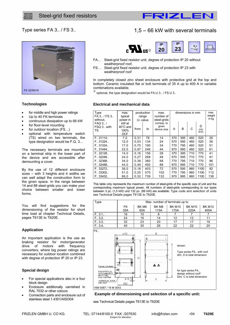
FRIZLEN GMBH U. CO KG. TEL: 07144/8100-0 FAX: /207630 [email protected] r04 T629E Subject for alteration
Steel-grid fixed resistors
Type series FA 3.. / FS 3.. Technologies for middle and high power ratings Up to 40 FK-terminals continuous dissipation up to 66 kW for floor-level mounting for outdoor location (FS…) optional with temperature switch
(TS) wired on two terminals, the type designation would be F.Q. 3...
The necessary terminals are mounted on a terminal strip in the lower part of the device and are accessible after demounting a cover. By the use of 12 different enclosure sizes – with 3 heights and 4 widths we can well adapt the construction form to the given space. In the range between 14 and 88 steel-grids you can make your choice between smaller and lower forms. You will find suggestions for the dimensioning of the resistor for short time load at chapter Technical Details, pages T613E to T620E. Application An important application is the use as braking resistor for motor/generator drive of motors with frequency converters, where big power ratings are necessary for outdoor location combined with degree of protection IP 20 or IP 23. Special design For special applications also in a four
block design Enclosure additionally varnished in
RAL 7032 or other colours Connection parts and enclosure out of
stainless steel 1.4301/AISI304
1,5 – 66 kW with several terminals FA... Steel-grid fixed resistor unit, degree of protection IP 20 without weatherproof roof, FS… Steel-grid fixed resistor unit, degree of protection IP 23 with weatherproof roof In completely closed zinc sheet enclosure with protective grid at the top and bottom. Ceramic insulated flat or bolt terminals of 35 A up to 400 A in variable combinations available.
optional, the type designation would be FA.U 3.. / FS.U 3..
Electrical and mechanical data
production range
value
dimensions in mm Type FA 3.. / FS 3.. without, FAQ 3.. / FSQ 3.. with TS
max. typical
power in kW at
40°C and 100% DCF
from to
max. number of steel-grids corresp. to
given device size A B C
D only IP23
max. weight in kg
F.. 31114.. 7,0 0,31 78 14 370 395 460 520 26F.. 31224.. 12,0 0,53 134 24 570 595 460 520 36 F.. 31334.. 17,0 0,75 190 34 770 795 460 520 51 F.. 31444.. 22,0 0,97 246 44 970 995 460 520 61 F.. 32128.. 14,0 0,16 156 28 370 395 710 770 41 F.. 32248.. 24,0 0,27 268 48 570 595 710 770 61 F.. 32368.. 34,0 0,38 380 68 770 795 710 770 86 F.. 32488.. 44,0 0,49 492 88 970 995 710 770 101 F.. 33272.. 36,0 0,18 403 72 570 595 960 1100 82 F.. 33302.. 51,0 0,25 570 102 770 795 960 1100 112 F.. 33432.. 66,0 0,32 739 132 970 995 960 1100 138
This table only represents the maximum number of steel-grids of the specific size of unit and the corresponding maximum typical power. All numbers of steel-grids corresponding to our types between 3 pc. (1,5 kW) und 132 pc. (66 kW) are available. Type code and selection of units see Technical Details pages T613E to T620E.
Max. number of terminals up to Type
FK 35A
BK M6 60A
BK M8 115A
BK M10 170A
BK M10 220A
BK M12 400A
F.. 3.1.. 16 10 8 7 7 7F.. 3.2.. 24 16 14 12 12 11 F.. 3.3.. 32 23 20 17 17 16 F.. 3.4.. 40 30 26 22 22 20
Example of dimensioning and selection of a specific unit: see Technical Details pages T613E to T620E
FS..
16M 0087 / 16 M 0043
IP
23
FS 3235416
IP
20
shown: Type series FS.. with roof dim. D is total dimension for type series FA.. design without roof! Dim. C is total dimension

T630E r04 FRIZLEN GMBH U. CO KG. TEL: 07144/8100-0 FAX: /207630 [email protected] Subject for alteration
Steel-grid fixed resistors
Type series FS 319.. / FS 320.. Technologies for smaller power ratings compact construction form continuous dissipation up to 5,0 kW units may be wall mounted ,
horizontal mounting not admitted for outdoor mounting (FS…) The necessary terminals are mounted in the lower part of the device and are accessible after demounting the cover. We can provide 2 flat or 2 bolt terminals M6 or M8. You will find suggestions for the dimensioning of the resistor for short time load at chapter Technical Details, pages T613E to T620E. Application On behalf of small dimensions and compact construction form this type series is especially appropriate as load resistor for small power ratings, if degree of protection IP 23 is necessary. A lot of applications are possible because of the high degree of protection and the wall mounting, such as the outdoor mounting. Special design degree of protection IP 20
(without roof), type FA 319.. / FA 320..
0,5 – 5,0 kW with 2 terminals Steel-grid fixed resistor unit, degree of protection IP 23 with weatherproof roof, appropriate for outdoor mounting, in zinc steel sheet enclosure, for connection with 2 terminals, with several holes for cable glands, that are closed by rubber sockets. Electrical and mechanical data
production range
value
dim. in
mm
max. weight in kg
type
max. typical
power in kW at
40°C and 100% DCF
from to
max. number of steel-grids corresp. to
given device size F
drills for cable lead-throughs
M
FS 3190602 3,0 0,11 33,6 6 200 9,5
FS 3201002 5,0 0,22 56,0 10 335
1 x PG 13,5 + 1 x PG 16 + 3 x PG21 12
This table only represents the maximum number of steel-grids of the specific size of unit and the corresponding maximum typical power. All numbers of steel-grids corresponding to our types between 1pc. (0,5 kW) and 10 pc. (5,0 kW) are available. . Example of dimensioning and selection of a specific unit:
One phase starting resistor as constant series resistor for motor 220 V DC; 8,5 kW, 51 A; resistor value 0,72 ; continuous dissipation approx. 1,9 kW; chosen: FS 3190402 – 0,72 with continuous dissipation 2 kW; this corresponds to 4 steel-grids S12 - 0,18 0,72 connection with 2 bolt terminals M6
FS 319 04 02 - 0,72 ohmic value 10% number of terminals number of steel-grids type series
FS 3..
16 M 0191
FS 3190506
IP
23

FRIZLEN GMBH U. CO KG. TEL: 07144/8100-0 FAX: /207630 [email protected] r04 T631E Subject for alteration
Steel-grid fixed resistors
Type series FAV 3../ FSV 3.. Technologies for high power ratings power ventilated by integrated
230/400 V; 50 Hz axial flow fan for floor-level location continuous dissipation up to 250 kW paralleling of 2 or more units for
even higher powers for outdoor location (FS…) The necessary terminals are mounted on a terminal strip in the lower part of the device and are accessible after demounting a cover. By the use of steel-grid elements with a typical power of 1100 W per steel-grid with forced ventilation we cover a power range of up to 250 kW per unit. Higher power ratings can be achieved by parallel connection of several devices. Application An important application is the use as load resistor for the testing of emergency power installations. Protection degree IP 20 is sufficient for installing in factory rooms, IP23 is necessary for outdoor location. Special design with integrated switching devices in
an attached switch cabinet to control the partial resistors
with 2 temperature switches wired on terminals.
special voltages of fan please ask for devices with higher
power ratings or other construction forms
mobile, for test areas by rollers
70 – 250 kW with several terminals FAV... Steel-grid fixed resistor unit, degree of protection IP 20,
without weatherproof roof, air outlet on top, FSV... Steel-grid fixed resistor unit, degree of protection IP 23
with weatherproof roof, for outdoor location, air outlet at the side via air deflectors in the upper area.
In completely closed zinc sheet enclosure with protective grid at the bottom and powered ventilation by an integrated ventilator. With air flow monitoring by wind indicator relay. Ceramic insulated flat or bolt terminals of 35A up to 400A in variable combinations available.
Electrical and mechanical data
dimensions in mm max. weight in kg
type FAV 3.. FSV 3..
max. typical
power in kW at
40°C and 100% DCF
max. number of steel-grids corresp. to
given size of device A B C D E F
F.V 38568.. 75 68 1200 1240 800 700 795 770 142F.V 38602.. 110 102 1500 1540 800 700 795 770 185 F.V 38776.. 185 176 1400 1450 955 850 995 970 265 F.V 38864.. 250 264 1700 1750 955 850 995 970 370
This table represents only the maximum number of steel-grids of the specific size of unit and the corresponding maximum typical power. Many specifications depending on customer requirement are possible. Standard load resistors for 3 x 230/400 V; 50 Hz type FAV..
partial resistors
in kW
FAV 3856609 75FAV 3856612 37,5/37,5 FAV 3869609 100 FAV 3869612 50/50 FAV 3860218 10/20/20/50 FAV 3876809 175 FAV 3876812 75/100 FAV 3876818 50/50/50/25 FAV 3884009 250 FAV 3884012 150/100 FAV 3884021 5 x 50
FAV.. 16 M 0182
type FSV..
partial resistors
in kW
FSV 3856609 75FSV 3856612 37,5/37,5 FSV 3869609 100 FSV 3869612 50/50 FSV 3860218 10/20/20/50 FSV 3876809 175 FSV 3876812 75/100 FSV 3876818 50/50/50/25 FSV 3884009 250 FSV 3884012 150/100 FSV 3884021 5 x 50
FSV.. 16 M 0088
FSV 3889212
IP
23 IP
20
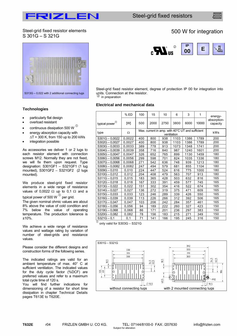
T632E r04 FRIZLEN GMBH U. CO KG. TEL: 07144/8100-0 FAX: /207630 [email protected] Subject for alteration
Steel-grid fixed resistors
Steel-grid fixed resistor elements S 301G – S 321G
Technologies particularly flat design overload resistant
continuous dissipation 500 W
energy absorption capacity with
T = 300 K, from 150 up to 200 kWs integration possible As accessories we deliver 1 or 2 lugs to each resistor element with connection screws M12. Normally they are not fixed, we will fix them upon request. Type designation: S301GF1 – S321GF1 (1 lug mounted), S301GF2 – S321GF2 (2 lugs mounted). We produce steel-grid fixed resistor elements in a wide range of resistance values of 0,0022 up to 0,1 and a
typical power of 500 W
per grid. The given nominal ohmic values are about 8% above the value of cold condition and 7% below the value of operating temperature. The production tolerance is ±10%. We achieve a wide range of resistance values and wattage rating by variation of number of steel-grids and resistance values. Please consider the different designs and construction forms of the following series. The indicated ratings are valid for an ambient temperature of max. 40° C at sufficient ventilation. The indicated values for the duty cycle factor (%DCF) are preferred values and refer to a maximum total cycle time of 120 s. You will find further indications for dimensioning of a resistor for short time dissipation in chapter Technical Details pages T613E to T620E.
500 W for integration
Steel-grid fixed resistor element, degree of protection IP 00 for integration into units. Connection at the resistor. in preparation Electrical and mechanical data % ED 100 15 10 6 3 1
typical power
[W] 500 2000 2750 3800 6000 10000
energy-absorption-
capacity
type Max. current in amp. with 40°C UT and sufficient
ventilation kWs
S301G – 0,0022 0,0022 400 800 938 1103 1386 1789 200S302G – 0,0027 0,0027 400 800 938 1103 1386 1789 200 S303G – 0,0033 0,0033 389 778 913 1073 1348 1741 200 S304G – 0,0039 0,0039 358 716 840 987 1240 1601 200 S305G – 0,0047 0,0047 326 652 765 899 1130 1459 180 S306G – 0,0056 0,0056 299 598 701 824 1035 1336 180 S307G – 0,0068 0,0068 271 542 636 748 939 1213 180 S308G – 0,0082 0,0082 247 494 579 681 855 1104 180 S309G – 0,010 0,010 224 447 524 616 775 1000 180 S310G – 0,012 0,012 204 408 479 563 707 913 180 S311G – 0,015 0,015 183 365 428 503 632 816 165 S312G – 0,018 0,018 167 333 391 459 577 745 165 S313G – 0,022 0,022 151 302 354 416 522 674 165 S314G – 0,027 0,027 136 272 319 375 471 609 165 S315G – 0,033 0,033 123 246 289 339 426 550 165 S316G – 0,039 0,039 113 226 266 312 392 506 165 S317G – 0,047 0,047 103 206 242 284 357 461 165 S318G – 0,056 0,056 94 189 222 260 327 423 150 S319G – 0,068 0,068 86 171 201 236 297 383 150 S320G – 0,082 0,082 78 156 183 215 271 349 150 S321G – 0,1 0,1 71 141 166 195 245 316 150
only valid for S303G – S321G
S313G – 0,022 with 2 additional connecting lugs
IP
00 E
M12
M12M12M12M12M12
S301G – S321G
without connecting lugs with 2 mounted connecting lugs

Frizlen GmbH u. Co. KGGottlieb-Daimler-Strasse 61 · D-71711 Murr · Tel. +49 (0) 7144 8100-0 · Fax +49 (0) 7144 207630www.frizlen.com · [email protected]
F R I Z L E N S O N D E R G E R Ä T ES P E C I A L D E V I C E S
SPECIAL
DC-Powerswitch
FRIZLEN DC-Powerswitch – Einstellbarer Schutz von
ohmschen Lasten an Gleichspannung bis 850 V. Fein
skalierbar für Nennströme von 1,0 bis 40 A. Eingebaut in
Widerstandsgeräte werden eigensichere Widerstände mit
Kurzschluss- und Überlastüberwachung mit Abschaltung
und Meldung erreicht. Die Schutzgeräte sind geeignet für
standardmäßigen Bremsbetrieb an Frequenzumrichtern.
DC-Powerswitch
FRIZLEN DC-Powerswitch – Adjustable safety at ohmic loads
connected on DC voltages up to 850 V. Fine adjustable scale
for nominal currents from 1,0 up to 40 A. Thanks to the
integration into power resistor devices, self secure power
resistors with short-circuit and overload protection and
monitoring can be achieved. The safety devices are suitable
for use with brake resistors at frequency converters.
Kundenspezifi sche Widerstandsgeräte
FRIZLEN fertigt mit nahezu 50 % seines Portfolios kunden-
spezifi sche Widerstände. Ob angebaut an integrierte
Motorumrichter, untergebaut unter Frequenzumrichter
oder als externe Widerstände mit speziellen mechanischen
und elektrischen Eigenschaften – FRIZLEN sucht gemeinsam
mit den Kunden nach der bestmöglichen Lösung.
Customised resistor units
FRIZLEN produces nearly 50 % of its portfolio as cus-
tomised resistor units. Attached to motor-frequency
converter-combinations, as foot print resistors to
frequency converters or as external resistors
with specialised mechanical or
electrical features – FRIZLEN
tries to fi nd the best solution
together with its customers.

FRIZLEN GMBH U. CO KG. TEL: 07144/8100-0 FAX: /207630 [email protected] r05 FPS_E Subject for alteration
Accessory
Type series FPS Technologies overload protection short circuit up to 5 kA, 1ms re-switchable 1,0 - 40 A rated current, DC1 up to 850 V DC for installation into a switch cabinet or
a terminal box of a FRIZLEN power resistor
for intrinsically safe resistors with signal contact Intrinsically safe resistors through FRIZLEN DC-POWERSWITCH These overload switches are developed to protect the integrated resistors from constant overload and from too high short time peak power, e.g. caused by a false operational mode or a fault by an short circuited chopper transistor. This option for protection signals not only the hardware fault, it switches off the object / the resistor absolutely reliable! Possible damage in the environment through overheating and burning are effectively avoided. The actual fault is reported over potential free N/O and N/C contacts. After a successful fault clearance the DC-Powerswitch can be switched on like a normal automatic fuse. Connection cross section
Fine stranded Connection up to Rated current max. AWG 8
FPS1.6-10, AWG14 FPS16, AWG12 FPS20-25, AWG10 FPS32-40, AWG8
Auxiliary current max. AWG 14
FPS1.6-40, AWG14
Contact ratings of the signal contact:
5 A / 24 VDC (DC11) 10 A / 230 VAC (AC11)
FRIZLEN DC-POWERSWITCH – 1,0 A up to 40 A FRIZLEN DC-POWERSWITCH. Adjustable protection of loads at DC voltage up to 850 V. Loads with a rated current from 1,0 up to 40 A can be connected. The tripping device and the characteristics are similar to motor-circuit switches. 10 ranges of adjustment are available. The DC-Powerswitch reacts on thermal overload, also electromagnetically on short circuit and on the multiple of the rated current. Registration: German patented design no. 20 2009 015 851.9 UL registration according to UL1077 with E357442 Electrical and mechanical data
Adjustment range
A-value
Adjustment range
A-value
Adjustment range
A-value
Type
from up to
Type
from up to
Type
from up to
FPS 1.6 1,0 1,6 FPS 10 6,3 10 FPS 32 25 32 FPS 2.5 1,6 2,5 FPS 16 10 16 FPS 40 32 40 FPS 4.0 2,5 4,0 FPS 20 16 20 FPS 6.3 4,0 6,3 FPS 25 20 25
FPS 1.6 – 16 FPS 20 - 40
Attention: Please pay attention for connecting the correct polarity!
FPS 1.6 – 25 FPS 32 - 40
FPS10
90,5
Con Con 5 3 1
6 4 2 11
24 12
23
DBGM 202009015851.9
68,2
43,8 6,0
68,2
44,5
45
,0
90,5
62,5
3 1
2
5
4 6
rated current DC rated current DC
seco
nds
seco
nds
min
utes
min
utes
upper setting value (OE)magnetical fast release lower setting value (UE)
upper setting value (OE) magnetical fast release lower setting value (UE)