DYNAMIC STIFFNESS OF FOUNDATIONS: 2-D YI. 3-D … · Jose M. Roesset Sponsored by the ... DYNAMIC...
48
NSF-RANN Grant No. AEN-741783S DYNAMIC STIFFNESS OF FOUNDATIONS: 2-D YI. 3-D SOLUTIONS Order No. 581 by MOSHE JAKUB October 1977· Supervised by Jose M. Roesset Sponsored by the National Science Foundation Division of Advanced Environmental Research and Technology Publication No. R77 -36
Transcript of DYNAMIC STIFFNESS OF FOUNDATIONS: 2-D YI. 3-D … · Jose M. Roesset Sponsored by the ... DYNAMIC...
NSF-RANN Grant No. AEN-741783S
DYNAMIC STIFFNESS OF FOUNDATIONS:2-D YI. 3-D SOLUTIONS
Order No. 581
by
MOSHE JAKUB
October 1977·
Supervised by
Jose M. Roesset
Sponsored by the National Science Foundation
Division of Advanced Environmental
Research and Technology
Publication No. R77-36
6. Ii1
~-.,---------------------------+~:--::--;---:::----;-:---::--' -7. Au:hor(s) 8. Performing Organiiation Rept. :i
~4oshe Jakub, supervi sed by Jose ~'1. qoesset No. R77-36. No. 581 -:j:,III',
9. Performing Organization Name and Address 10. Proje"t/Task/Work Unlt No.I,
~1assachusetts Institute of Technology ~--::---..,..,....-------!IDept. of Civil Engineering 11. Cor,tract/Gra"t No, jl77 Mass. Ave. ~
l-J"'::amib.l:..j·l..di rI~""oe..,.-lt~1A-Il..Qn.z.?"~1~Q_--,- +-N::!.:S~F~RAjfN!.!.':!N..JA!jlE~Nl.:.-L::.7Ll.:l:J,l..L.7.Q.;83,L;;5L.- -ii'12. Sponsori~g Organiiatio; Name and Address 13. Type of Report & Period IINational Science Foundation Covered 1:
1800 "G" St., N.t,I. Research 1976-1977 ,!rWash i ngton, D. C. 20550 r:1o-:4-.~~~"':"":"~""':""::"';'-:'--'li
I,1;
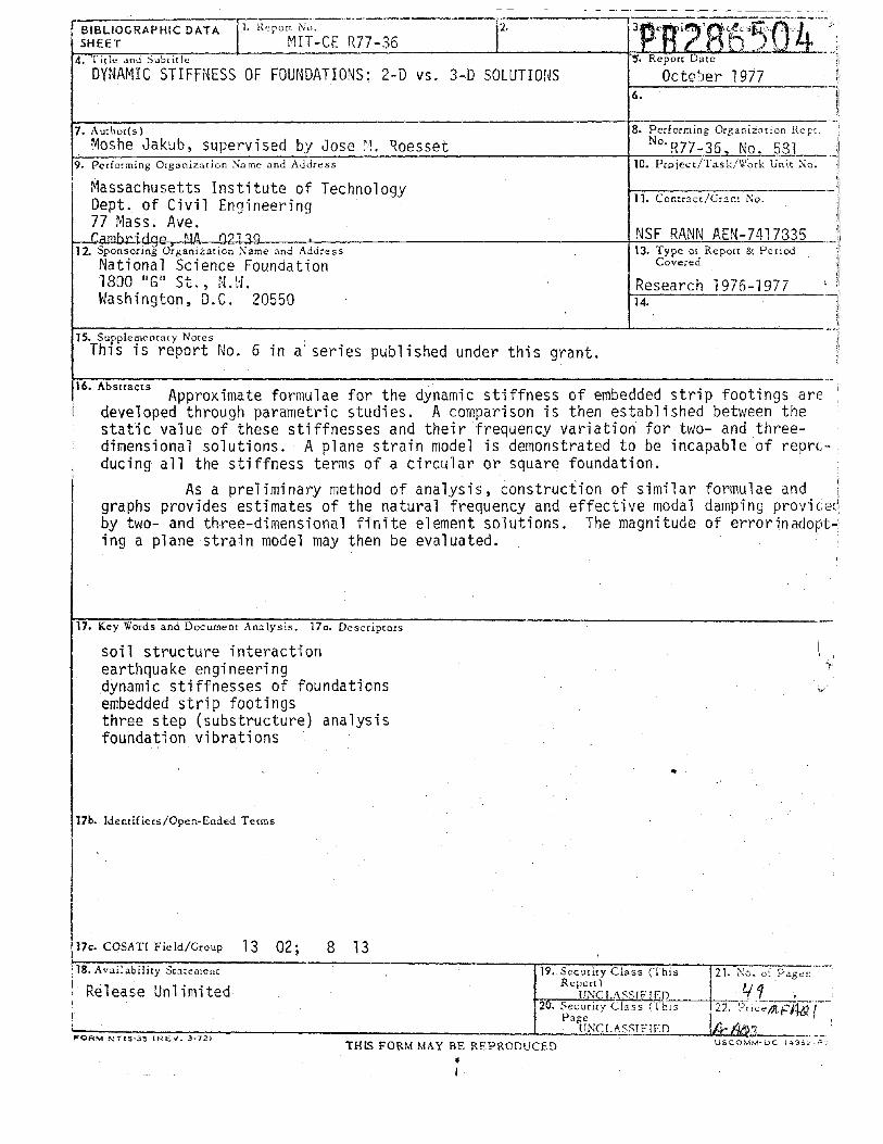
15. Supplementary NotesThlS is report No.6 in a'series published under this grant.
16. Abstracts Approximate formulae for the dynamic stiffness of embedded strip footings aredeveloped through parametric studies. A comparison is then established between thestatic value of these stiffnesses and their frequency variation for two- and threedimensional solutions. A plane strain model is demonstrated to be incapable of reprcducing all the stiffness terms of a circular or square foundation.
As a preliminary method of analysis, construction of similar formulae andgraphs provides estimates of the natural frequency and effective modal damping providedby two- and three-dimensional finite element solutions. The magnitude of errorinadopt-!ing a plane strain model may then be evaluated.
17. Key \li'ords and Document Analysis. 170. Descriprors
soil structure interactionearthquake engineeringdynamic stiffnesses of foundationsembedded strip footingsthree step (substructure) analysisfoundation vibrations
..
17b. Idenrifiers/Open-Ended Terms
8 13
Release Unlimited
17c. CaSATI Fie ld/Croup 13 02;18. Availabiliry Statement 19. Security Class (This 21. :-:0. or Pag,,~
Report) 4,' 4 "f;:;jo:;-c:-_l",-,JN~'C,,-,-1,,;,.A'"7-"""".w..[1'..;-,'1E>;;.:',D.~_-+-::,--:::--, '
20. Security Class (This 22. '5;i~-;;/;t,F!Uif'-'-Page
~;;-;:;-:;-;;:-;:-;:;-;-;;;-;;-:;--:;:;-;;- -1.__~U:.:.cN~Cc!.:I.LlA.:::SS,,-!I.::..F.!1Ir..:2:'D~_-.Ii~i1-.. .f:1;{J(~'3.' _FORM NTIS"3~ (REY~ 3·72) TH[S FORM MAY BE REPRODUCED USCOMM·DC 1495~·':'~
•I
•
Massachusetts Institute of Technology
Department of Civil EngineeringConstructed Facilities DivisionCambridge, Massachusetts 02139
DYNAMIC STIFFNESS OF FOUNDATIONS:2-D vs. 3-D SOLUTIONS
by
MOSHE JAKUB
Supervised by
Jose M. Roesset
October 1977
Sponsored by the National Science FoundationDivision of Advanced Environmental Research and Technology
NSF-RANN Grant No. AEN-7417835
Publication No. R77-36 Order No. 581
r
2
ABSTRACT
Most computer programs used at present for soil structure interaction analyses are based on a two-dimensional (or pseudo three-dimensional) model of the soil. In this work the results of parametric studies are presented, leading to approximate formulae for the dynamicstiffnesses of embedded strip footings similar to those already available for circular foundations. A comparison is then established betweenthe static values of these stiffnesses and their frequency variation fortwo- and three-dimensional solutions. It is shown that a plane strainmodel cannot reproduce all the stiffness terms of a circular or squarefoundation over the complete range of frequencies. Recognizing, on theother hand, that not all the terms may contribute significantly to thestructural response, it is recommended that for each particular problem,before embarking on the use of finite element programs, preliminary analyses be conducted with formulae and graphs similar to those presented here,in order to estimate the natural frequencies and effective modal dampingprovided by two-dimensional and three-dimensional solutions. These estimates will allow assessment of the order of magnitude of the error involved in a plane strain model and will indicate whether more expensivestudies with such a model are justified.
3
PREFACE
The work described in this report was conducted by Moshe Jakub,a graduate research assistant in the Civil Engineering Department atM.I.T., under the supervision of Professor Jose M. Roesset. It wasmade possible through Grant AEN 7417835 from the National Science Foundation, Division of Advanced Environmental Research and Technology.
This is the sixth of a series of reports published under thisgrant. The other five were:
1. Research Report R76-8 by Mohammed M. Ettouney, "TransmittingBoundaries: A Comparison,1I January 1976.
2. Research Report R76-9 by Mohammed M. Ettouney, IINon1inearSoil Behavi or in Soil Structure Interacti on Ana1ysis," February 1976.
3. Research Report R77-30, by Jose J. Gonzalez, IIDynamic Interaction between Adjacent Structures,1I September 1977.
4. Research Report R77-33 by F. E1sabee and J.P. Morray, "Dynamic Behavior of Embedded Foundations,1I September 1977.
5. Research Report R77-35, by Moshe Jakub, IINon1inear Stiffnessof Foundations,1I September 1977.
4
DYNAMIC STIFFNESS OF FOUNDATIONS: 2-D vs. 3-D SOLUTIONS
INTRODUCTION
A considerable amount of work has been done in recent years todetermine the dynamic stiffnesses of foundations of various shapes, aproblem of interest on its own (as for the design of machine foundations), but of particular importance in relation to the seismic analysis of nuclear power plants. Analytical solutions have been presentedand tabulated for circular foundations on the surface of an elastic(15) or viscoelastic (16) halfspace, and algorithms have been developedto study circular and rectangular foundations (or for that purpose foundations of arbitrary shape) on the surface of a horizontally stratifiedsoil deposit (4,9,18). These analytical or semi-analytical solutionshave been limited until now to surface foundations and linear soil behavior, but approximate procedures to account for the effect of embedment (3,12,13,14) and for the nonlinear characteristics of soils (7)have also been suggested. Finally, finite element solutions are alsoavailable to study circular foundations embedded or on the surface (6)and surface footings of arbitrary shape (5).
In spite of all this work, most of the computer programs used inpractice, such as LUSH (10), are based on a two-dimensional (plane strain)model of the soil and the structure. Even a more recent version, FLUSH(11), which claims to solve the three-dimensional problem has in fact aplane strain model with viscous dashpots added to the lateral faces inorder to increase the radiation damping (this is at best a pseudo threedimensional solution).
The main reason invoked for the use of two-dimensional models isone of economy: the solution of a completely three-dimensional model foran embedded foundation of arbitrary shape and a soil profile with variableproperties and nonlinear behavior is today prohibitively expensive (although the only problem in the formulation of such a model is the deriva
tion of realistic constitutive equations for the soil). This argument
5
would imply that these two effects are accurately reproduced in presentprograms and that the increased accuracy over the approximate solutionsmentioned above more than compensates for the errors introduced by thetwo-dimensional idealization. The first point is not entirely correct.Present finite element solutions assume perfect welding between thesidewalls of the foundation and the surrounding soil, but the actual conditions of the backfill, often uncertain, may significantly influence theeffective depth of embedment; nonlinear soil behavior is normally simulated through an equivalent linearization technique, using an iterativescheme which requires several arbitrary assumptions; thus whether thereis in fact an important increase in accuracy in these finite element modelsmay be questionable. The second point requires more extensive studiesthan those conducted to date in order to assess the magnitude of the potential errors introduced by plane strain models (or the modified versions)for typical situations.
PREVIOUS WORK
In 1974 Kausel (16) conducted a comparative study for a typical containment building using both a cylindrical finite element formulation,reproducing the exact three-dimensional condition for a horizontal seismicexcitation, and an equivalent two-dimensional model. The building had acircular foundation with a radius of 57.5 ft. and was embedded 55 ft. ina soil stratum with a total depth of 170 ft. The shear wave velocity ofthe soil varied from 428 ft/sec at the surface to 934 ft/sec at the bottom,and the stratum was underlain by competent rock which was simulated as arigid base. In the 2-D model the structure was represented by two coaxialcolumns of lumped masses and springs, attached to a massless, rigid foundation with flexible sidewalls. Masses and stiffnesses were normalized withrespect to an equivalent width 2B, obtained by equating the area of asquare foundation to that of the actual circular mat. The properties ofthe flexible sidewalls (deforming mainly in flexure) were selected so asto yield the same horizontal displacement at grade level as the cylindricalwall (deforming mainly in shear) under a uniform lateral load.
6
The results of this study indicated that for the case consideredthe agreement between the two models was reasonable and probably goodenough for practical purposes. Differences in the amplified responsespectra at various levels of the structure were of the order of 15%.
Luco and Hadjian (8), on the other hand, considered the case of astructure resting on the surface of an elastic, homogeneous halfspace.For this case they presented and discussed various alternatives for theselection of the width and thickness (out of the plane) of a strip footingso as to match the average values of the stiffness and damping terms ofa circular foundation over a certain frequency range (it should be noticedthat the static stiffness of a strip footing on a halfspace is zero).They decided that the best approach was to select the halfwidth of thefooting B = O.816R and the total thickness 2C = 1.25 x (2R) in order to
match the stiffnesses; the natural frequencies of the soil structure system would remain then unchanged, a factor they considered of primary importance for the determination of equipment response. In this way, however, the damping terms for the strip footing were larger than for thecircular foundation (32% in swaying and 18% in rocking over the high frequency range, and substantially more for low values of the dimensionlessfrequency ao). Using this approach, they determined amplified responsespectra at the base, top of the internal structure, and top of the containment building for a structure with a fundamental frequency of 3 cps on arigid base, and 0.74 and 1.29 cps on the elastic foundation (with shearwave velocities for the soil of 600 and 1150 ft/sec respectively). Thespectra at the top of the structures had peaks at the natural frequencieswhich were approximately 50% higher for the three-dimensional solution thanfor the equivalent two-dimensional model.
Several points of this study deserve careful consideration. In thefirst place, the selection of the equivalent width and thickness does notseem to be the most appropriate; while it is important to reproduce reasonably well the natural frequencies of the soil structure system, it shouldbe noticed that these frequencies will vary at most with the square rootof the foundation stiffnesses. Thus an error of even 25 or 30% on these

,
7
stiffnesses will represent only an error of at most 10 to t5% onthe frequencies (the error being larger as the soil becomes softer andthe stiffnesses decrease). Considering the uncertainties in the actualvalues of the soil properties (both their values in situ for low levelsof strain and their variation with shear strain), and even in the structural characteristics,this error does not seem unreasonable (one shouldconsider in any case variations in the soil parameters and not rely ona single analysis). Reproduction of the radiation damping, particularlyin rocking and in the neighborhood of the natural frequency of the combined system, would appear to be more important in order to obtain sensible results.
In the second place the unusually small natural frequencies of thestructure on elastic foundation make the error in the radiation dampingconsiderably larger than the 32 or 18% predicted by the formulae for thehigh frequency range (the effective values of damping in the first modewere 2.3 and 1.8% for the three-dimensional solution and 6.36 and 5% forthe two-dimensional one). The fact that no internal damping was assumedfor the soil aggravates the situation; clearly the difference in the results from 2% damping to a value of 5% is much larger than from, say,7 to 11% or 12 to 16%.
Because of these facts one should expect that the differences between the two solutions would not be as large as the reported 50% inpractical situations. It is important to realize, however, that differences will exist and that, as pointed out by the authors, it is not possible to select an equivalent two-dimensional model which will match allthe stiffness terms over the complete frequency range. Furthermore, thefact that the radiation damping will be generally overestimated by theequivalent strip footing would indicate that increasing the dissipationof energy by adding viscous dashpots may make the situation worse insteadof improving it.
In 1975 Berger, Lysmer and Seed (1) presented results of anothercomparative study. They concluded that the differences between their
8
three-dimensional and their two-dimensional solutions, which were againsignificant, were due to deficiencies in the structural model, whichwould be an obvious source of errors. The horizontal component of motionat the base of the structure was, however, very similar for the two cases,and the study recommended the use of a complete two-dimensional soilstructure model to obtain the base motion and then the use of an independent structural analysis program with a three-dimensional model of thebuilding and the computed motion at the base to determine the structuralresponse. A proper justification of this approach, beyond the comparisonof the translational components of the base motion, was, however, lacking,and the rotational component which would be an important part of the totalmotion was not presented (and seemed to be ignored).
Finally Lysmer et al. (11) showed results for a nuclear reactor andtwo adjoining buildings using a purely two-dimensional model and the pseudothree-dimensional solution. Since the only difference between the two modelsis an increase in damping for the latter, the response in this case wassignificantly smaller (about 50%) when simulating three-dimensional effects,contrary to most of the other comparisons. The fact that a true three-dimensional solution was not presented and that there were two adjoining structures which were very deeply embedded make this example inappropriate foran adequate evaluation of the errors introduced by the two-dimensionalapproximation.
SCOPE
It is clear that the use of a plane strain finite element model forthe analysis of a structure resting on the surface of an elastic, homogeneous, halfspace is entirely unjustified. Not only are the available analytical solutions (15, 16) much more accurate than those that could beobtained with the discrete formulation, but the use of these solutionswith the three-step approach (or substructure method) would be considerably more economical than the direct (or one-step) solution of the completesoil structure system with any of the available computer programs (LUSH
or FLUSH).
9
In most practical cases, however, the soil properties will not be
uniform with depth (the shear modulus will normally increase) or a deposit of finite depth will be underlain by much stiffer, rock-like material. The elastic, uniform halfspace is therefore a mathematical idealization rather than a true physical condition. In addition, most structural foundations, and those of nuclear power plants especially, willhave some degree of embedment.
The purpose of this work is to conduct further comparisons betweentwo-dimensional and three-dimensional solutionsby obtaining approximateexpressions for the dynamic stiffnesses of embedded strip footings andcomparing them to those presented by Elsabee(3) for circular foundations.
The dynamic behavior of strip footings had already been extensivelystudied by Chang Liang (2), who presented a series of curves relatingthe static stiffnesses (and particularly the flexibilities) to layerdepth and embedment. Here, following the work of Kausel (6) and Elsabee(3) for circular foundations, the static stiffnesses are determined firstfor surface foundations and approximate formulae are fitted to the numerical results. Parametric studies are conducted next for embedded foundations, within the range of embedment ratios of practical interest, andcorrective factors are obtained by fitting straight lines. Finally, thevariation with frequency of the stiffness coefficients is studied.
The importance of the error introduced by a two-dimensional idealization will depend in a practical situation on the characteristics of thesoil profile and the structure considered. (It will be obviously negligible if the soil structure interaction effect is small). Using the results presented in this work and those already available for circularfoundations one can, in each specific situation, carry out some simplepreliminary computations to estimate the natural frequencies of the soilstructure system and the effective modal damping for both types of modelsbefore embarking on expensive computer runs. This will allow the assess
ment of the validity of a plane strain analysis.

10
FORMULATION
The parametric studies for surface foundations were carried outwith an analytical-type formulation developed by Gazetas (4) and witha finite element model implemented by Chang Liang (2). The former isonly applicable to a dynamic situation, i.e. to values of the frequencyof vibration different from zero: the static stiffnesses were then obtained by extrapolating the values in the low frequency range. Thelatter discretizes the soil under the footing by a finite element meshand places the consistent transmitting boundary developed by Waas (17)directly at the edge of the foundation. This boundary has been shownto reproduce with great accuracy the radiation of waves from the coreregion into the far field. By using these two approaches, with almostidentical results, the validity of the extrapolation procedure to determine the static stiffnesses in the analytical solution and the adequacy of the finite element meshes used could be checked (two mesheswere actually used, and a linear extrapolation was applied to obtainimproved estimates).
The results for embedded foundations were obtained in all caseswith the finite element model, assuming a massless, rigid foundationwith the sidewalls (also rigid) welded to the backfill. In order toisolate the effect of embedment, the static stiffnesses were divided bythose of an identical footing on the surface. To compute these ratiosthe values used were the ones corresponding to the same finite elementmeshes.
The variation of the dynamic stiffnesses with frequency was studiedfor surface foundations using again the analytical-type solution ofGazetas (4). For this purpose the stiffnesses were written in the form
Kx = Kxo(kl + i aocl)(l + 2iD)
K~ = K~o(k2 + i aoc2)(l + 2iD)
where Kxo and K~o are the static values.kl k2 cl c2 are the stiffness coefficients, function of frequency.

11
o is the internal damping in the soil, of a hysteretic nature(frequency independent).
ao = QB/cs is a dimensionless frequency; Q is the frequency ofexcitation in rad/sec; B is the halfwidth of the footing, andCs is the shear wave velocity of the soil.
STATIC STIFFNESSES
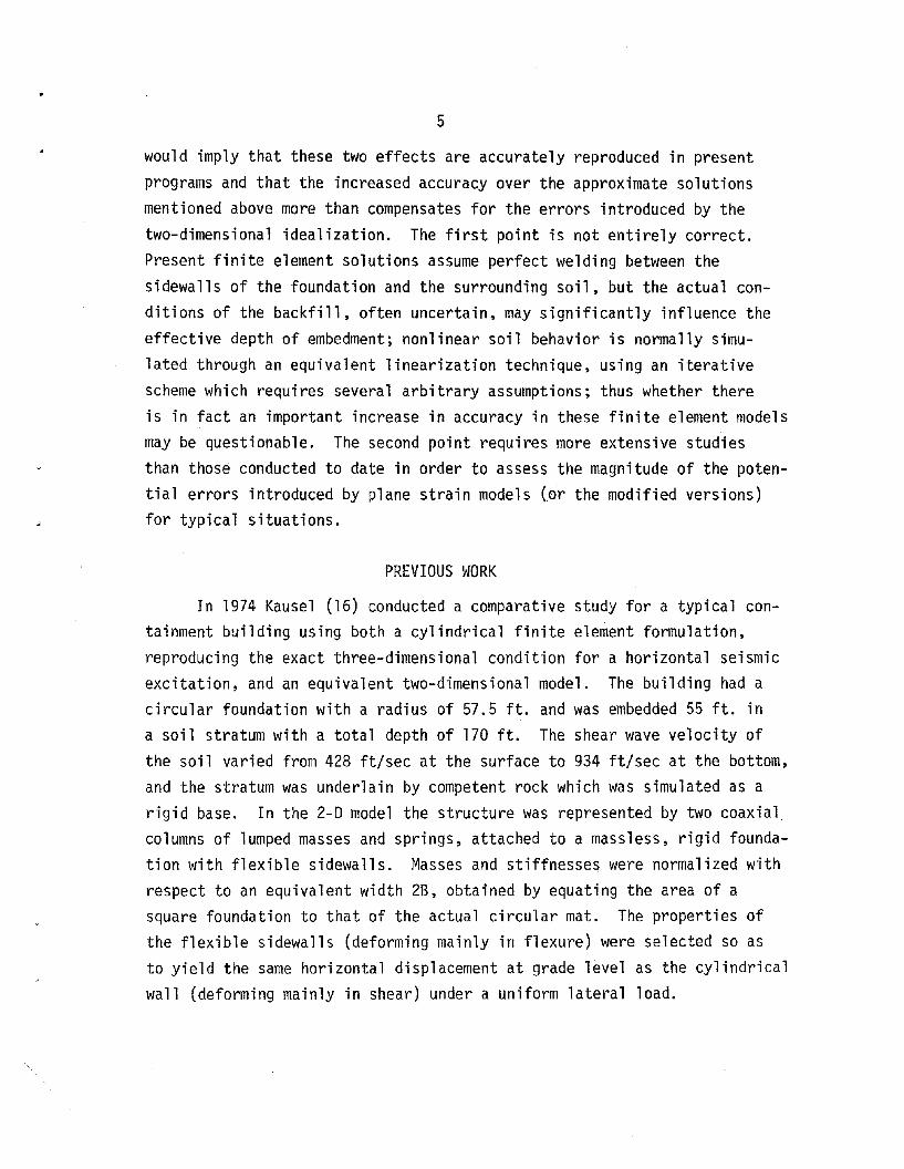
~~~f~~~_E~~~~~!!~~~. Figure 1 shows the variation of the horizontalstatic stiffness with layer depth for different values of Poisson'sratio v(O, 0.15, 0.3 and 0.45). It can be seen that for values of theratio B/H (B is the halfwidth of the footing and H the thickness ofthe soil stratum) larger than 1/4, the computed values fall almostexactly on a straight line. For deeper strata the stiffness decreasesmuch faster and tends, obviously, to zero as H increases.
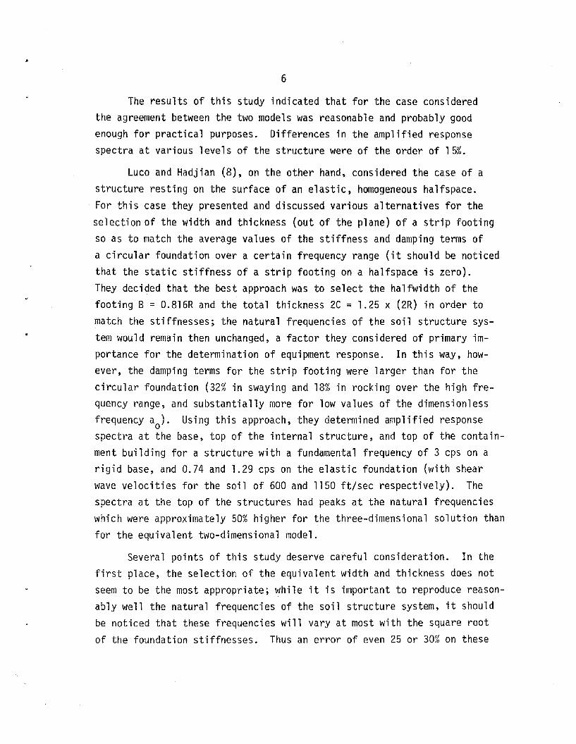
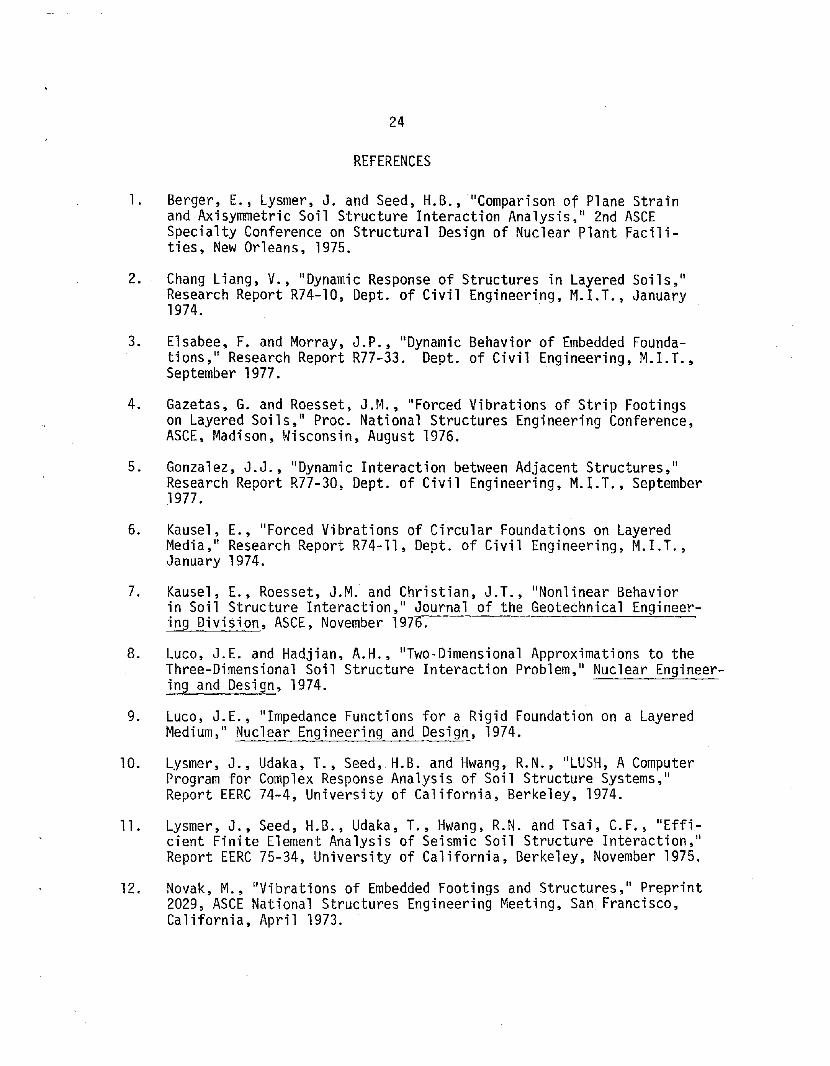
Figure 2 shows the corresponding results for the rocking stiffness.The values for a halfspace are now finite (nonzero). The variation overthe complete range studied, up to values of B/H = 1, is no longer linearbut more closely parabolic. It should be noticed, however, that H = 2Brepresents already a rather shallow stratum (thickness equal to totalfoundation width). The range of practical interest may then be reducedto values of H/B from 1/8 to 1/2. Within this range linear approximations can furnish reasonable results.
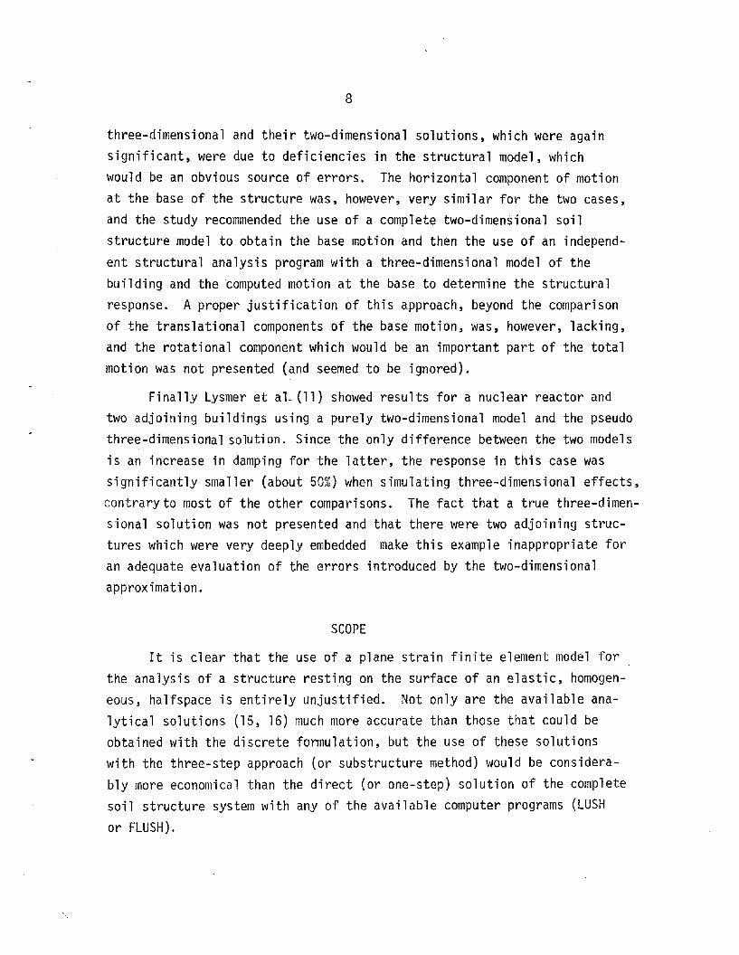
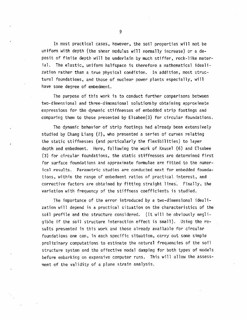
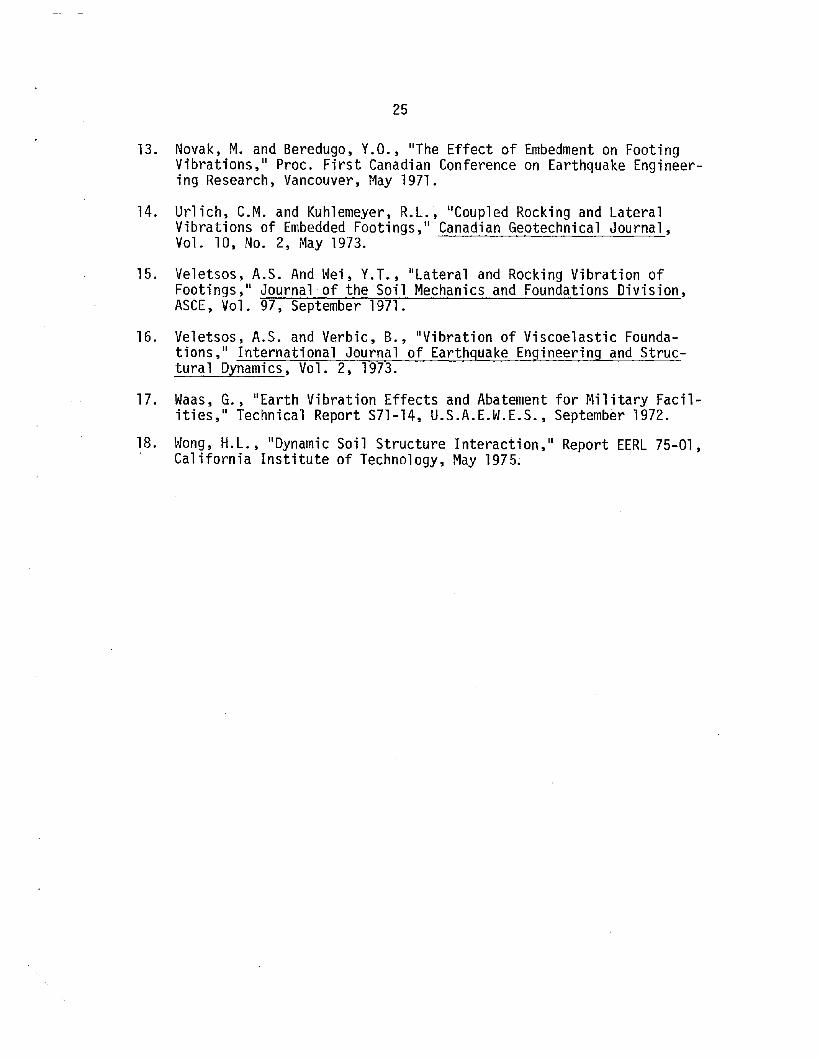
By comparison, figure 3 shows the varation of the static stiffnessesversus layer depth for a circular foundation, as reported by Kausel (6),and figure 4 the same results for a square foundation with sides = 2B ascomputed by Gonzalez (5). Notice that in both cases the studies werelimited to the range of R/H or B/H from 1/8 to 1/2.
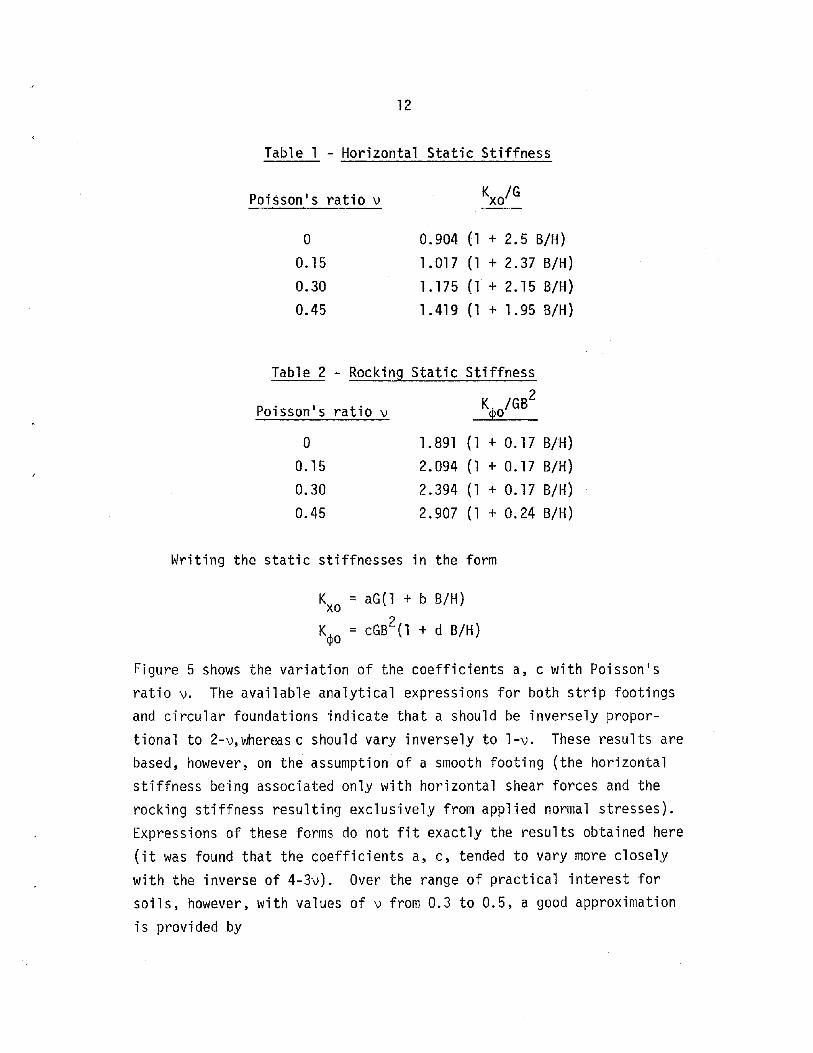
For this reduced range straight lines were fitted to the computedstiffnesses. The resulting formulae are shown in tables 1 and 2.
12
Table 1 - Horizontal Static Stiffness
Poisson's ratio v
o0.150.300.45
K /Gxo
0.904 (1 + 2.5 B/H)
1.017 (1 + 2.37 B/H)1.175 (1 + 2.15 B/H)1.419 (1 + 1.95 B/H)
Table 2 - Rocking Static Stiffness
Poisson's ratio v KpO/GB2
o0.150.300.45
1.891 (1 + 0.17 B/H)2.094 (1 + 0.17 B/H)2.394 (1 + 0.17 B/H)2.907 (1 + 0.24 B/H)
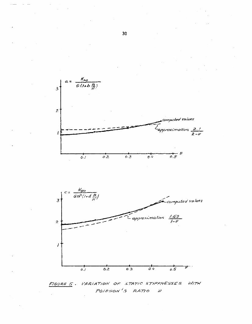
Writing the static stiffnesses in the form
Kxo = aG(l + b B/H)
K~o = cGB2
(1 + dB/H)
Figure 5 shows the variation of the coefficients a, c with Poisson'sratio v. The available analytical expressions for both strip footingsand circular foundations indicate that a should be inversely proportional to 2-v, whereas c should vary inversely to l-v. These results arebased, however, on the assumption of a smooth footing (the horizontalstiffness being associated only with horizontal shear forces and therocking stiffness resulting exclusively from applied normal stresses).Expressions of these forms do not fit exactly the results obtained here(it was found that the coefficients a, c, tended to vary more closelywith the inverse of 4-3v). Over the range of practical interest forsoils, however, with values of v from 0.3 to 0.5, a good approximation
is provided by
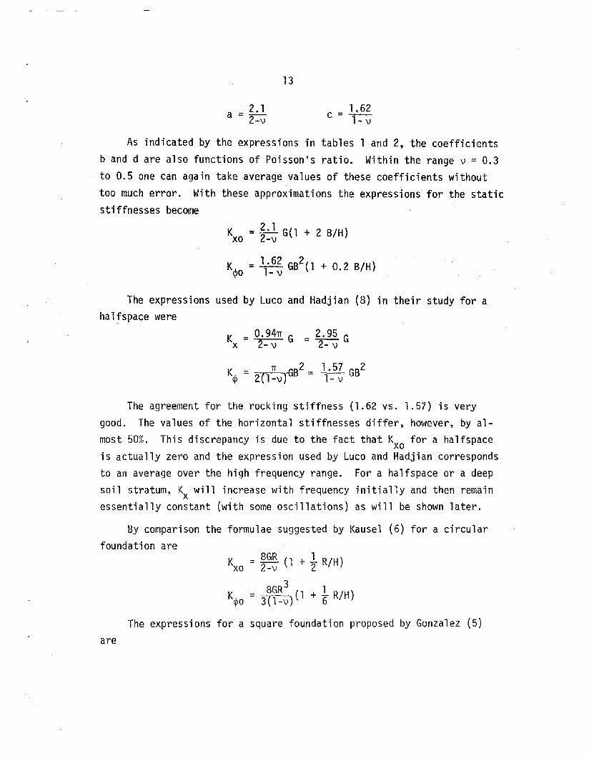
a =~2-v
13
1.62c =~1··... v
As indicated by the expressions in tables 1 and 2, the coefficientsband d are also functions of Poisson's ratio. Within the range v = 0.3
to 0.5 one can again take average values of these coefficients withouttoo much error. With these approximations the expressions for the staticstiffnesses become
K = 2.1 G(l + 2 B/H)xo 2-v
K = 1.62 GB2(l + 0 2 B/H)q>o 1- v •
The expressions used by Luco and Hadjian (8) in their study for ahalfspace were
K = 0.94TI G ~ 2.95 Gx 2- v 2- v
The agreement for the rocking stiffness (1.62 vs. 1.57) is verygood. The values of the horizontal stiffnesses differ, however, by almost 50%. This discrepancy is due to the fact that Kxo for a halfspaceis actually zero and the expression used by Luco and Hadjian correspondsto an average over the high frequency range. For a halfspace or a deepsoil stratum, Kx will increase with frequency initially and then remainessentially constant (with some oscillations) as will be shown later.
By comparison the formulae suggested by Kausel (6) for a circularfoundation are
K = 8GR (1 + 1 R/H)xo 2-v 2
3K = 8GR (1 + 1 R/H)~o 3(l-v) 6
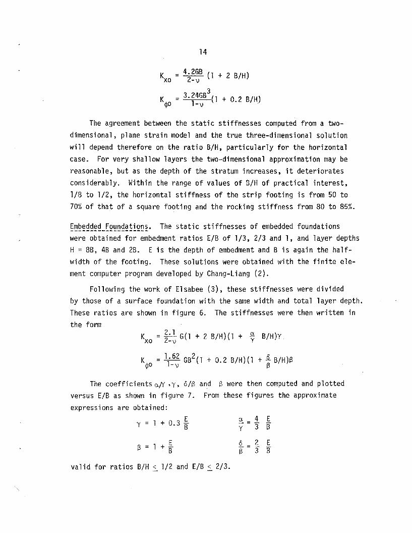
The expressions for a square foundation proposed by Gonzalez (5)are
14
Kxo
= 4.2GB (1 + 2 B/H)2-v
3K = 3.24GB (1 + 0.2 B/H)
</JO l-v
The agreement between the static stiffnesses computed from a twodimensional, plane strain model and the true three-dimensional solutionwill depend therefore on the ratio B/H, particularly for the horizontalcase. For very shallow layers the two-dimensional approximation may bereasonable, but as the depth of the stratum increases, it deterioratesconsiderably. Within the range of values of B/H of practical interest,1/8 to 1/2, the horizontal stiffness of the strip footing is from 50 to70% of that of a square footing and the rocking stiffness from 80 to 85%.
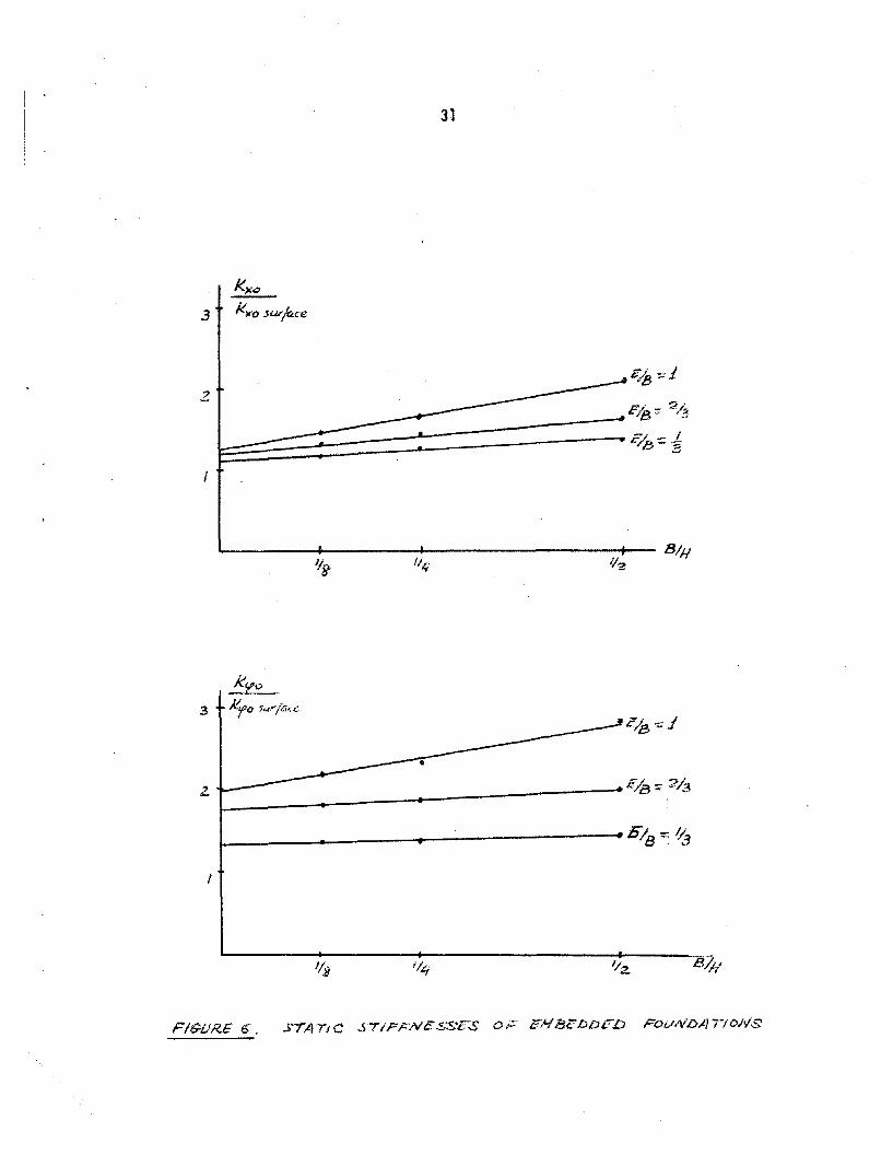
Embedded Foundations. The static stiffnesses of embedded foundations--------------------were obtained for embedment ratios E/B of 1/3, 2/3 and 1, and layer depthsH = 8B, 4B and 2B. E is the depth of embedment and B is again the halfwidth of the footing. These solutions were obtained with the finite element computer program developed by Chang-Liang (2).
Following the work of Elsabee (3), these stiffnesses were dividedby those of a surface foundation with the same width and total layer depth.These ratios are shown in figure 6. The stiffnesses were then written inthe form
K = 22.1 G(l + 2 B/H)(l + _ya B/H)Yxo -v
K = 1.62 GB2(1 + 0.2 B/H)(l + ~ B/H)B</>0 l-v B
The coefficients a/Y ,y, o/Sversus E/B as shown in figure 7.expressions are obtained:
EY = + 0.3 B
S = 1 + IB
and S were then computed and plottedFrom these figures the approximate
a 4 EY= 3" B
<5 2 ES = 3" B
valid for ratios B/H ~ 1/2 and E/B ~ 2/3.
15
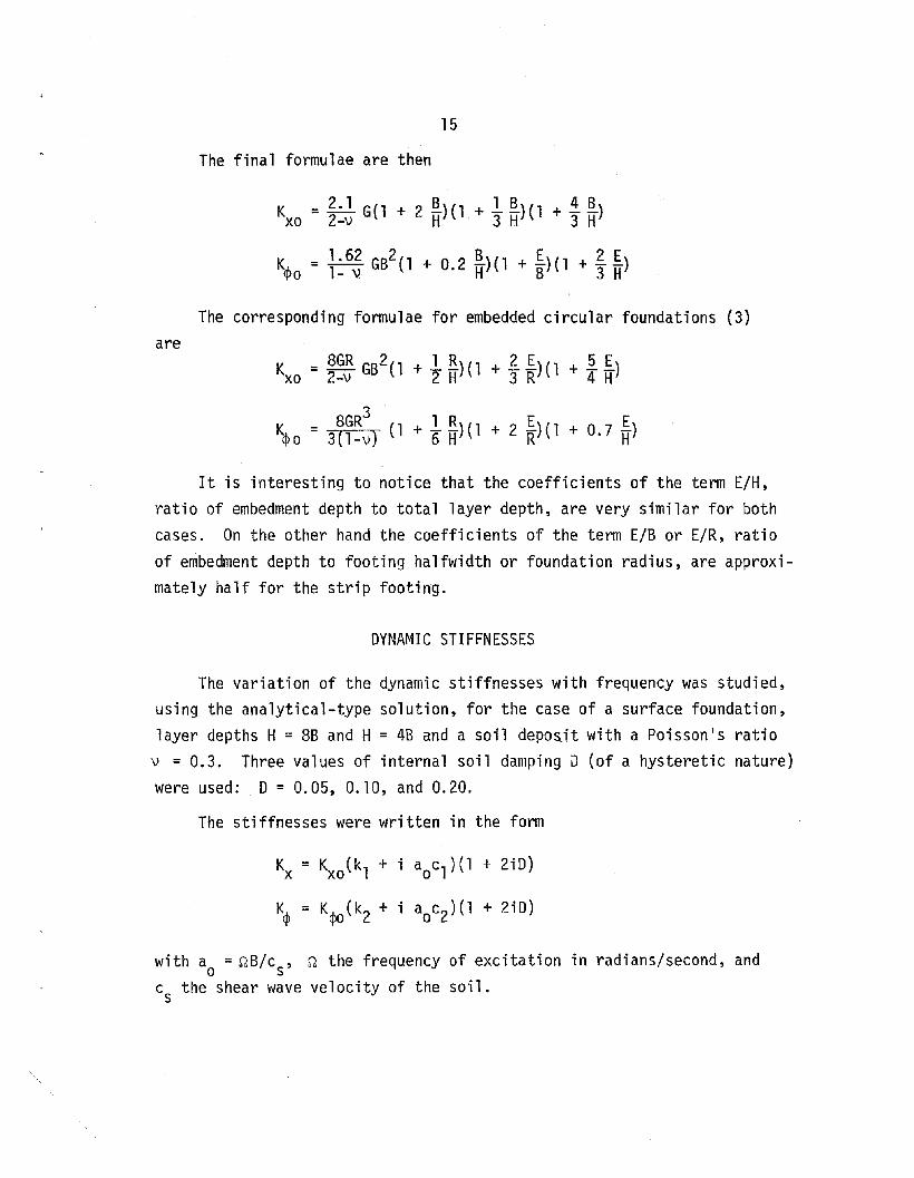
The final formulae are then
K = 2.1 G(l + 2 .!!)(l + 1.!!)(1 + .1. .!!)xo 2-v H 3 H 3 H
The corresponding formulae for embedded circular foundations (3)
are
8GR3 1 R E EK~o = 3(1-v} (1 + 6 H)(l + 2 R)(l + 0.7 H)
It is interesting to notice that the coefficients of the term E/H,ratio of embedment depth to total layer depth, are very similar for bothcases. On the other hand the coefficients of the term E/B or E/R, ratioof embedment depth to footing halfwidth or foundation radius, are approximately half for the strip footing.
DYNAMIC STIFFNESSES
The variation of the dynamic stiffnesses with frequency was studied,using the analytical-type solution, for the case of a surface foundation,layer depths H = 8B and H = 4B and a soil depo£it with a Poisson's ratio
v = 0.3. Three values of internal soil damping D (of a hysteretic nature)were used: 0 = 0.05,0.10, and 0.20.
The stiffnesses were written in the form
Kx = Kxo (k1 + i aoc1)(1 + 2iO)
K~ = K~(k2 + i aoc2)(1 + 2iO)
with a = ~B/c , ~ the frequency of excitation in radians/second, ando s
c the shear wave velocity of the soil.s

16
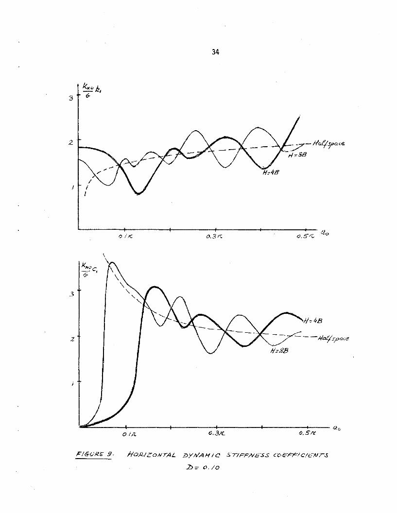
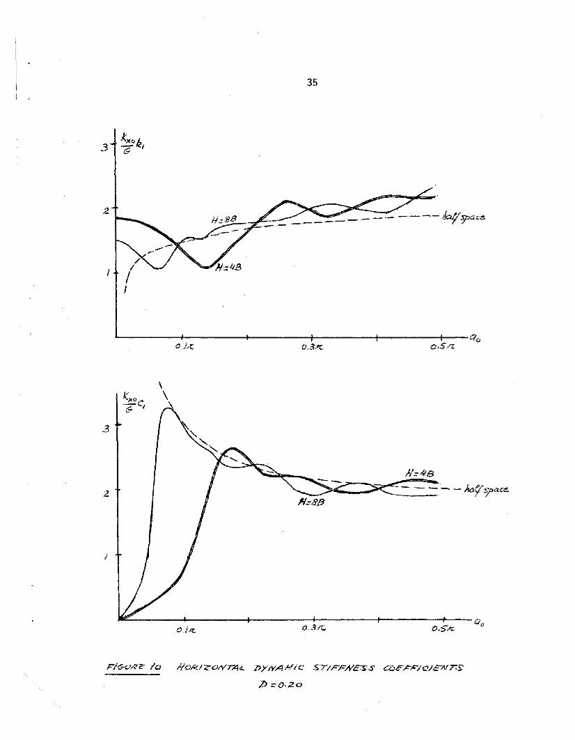
Figures 8 to 10 show the variation of the horizontal stiffnessesK K~o kl and ~o cl ' versus ao for the three values of D considered. It
can be noticed that while the stiffnesses are strongly dependent on theratio B/H in the low frequency range (including the static case) thevalues in the higher frequency range oscillate around those of the halfspace (these oscillations correspond to the natural frequencies of thesoil stratum). As the internal damping increases, these oscillationsbecome less pronounced, and the effect of finite depth of the layer tends
Kto disappear. The values of ~o kl increase slightly with increasing D,but this increase is relatively small for typical values of damping insoils (of the order of 5 to 10%). The complex term of the dynamic stiff-
Kxoness, ~ cl ' would be zero below the fundamental shear frequency of an
elastic stratum (ao =~ ~), since in this range of frequencies there can
not be any radiation of waves into the far field. Above this frequency,the values of this term approach again those corresponding to a halfspacewith some oscillations. The effect of the internal soil damping D is todecrease these oscillations and to provide for a smoother continuoustransition from the zero value for the static case to the halfspace values.
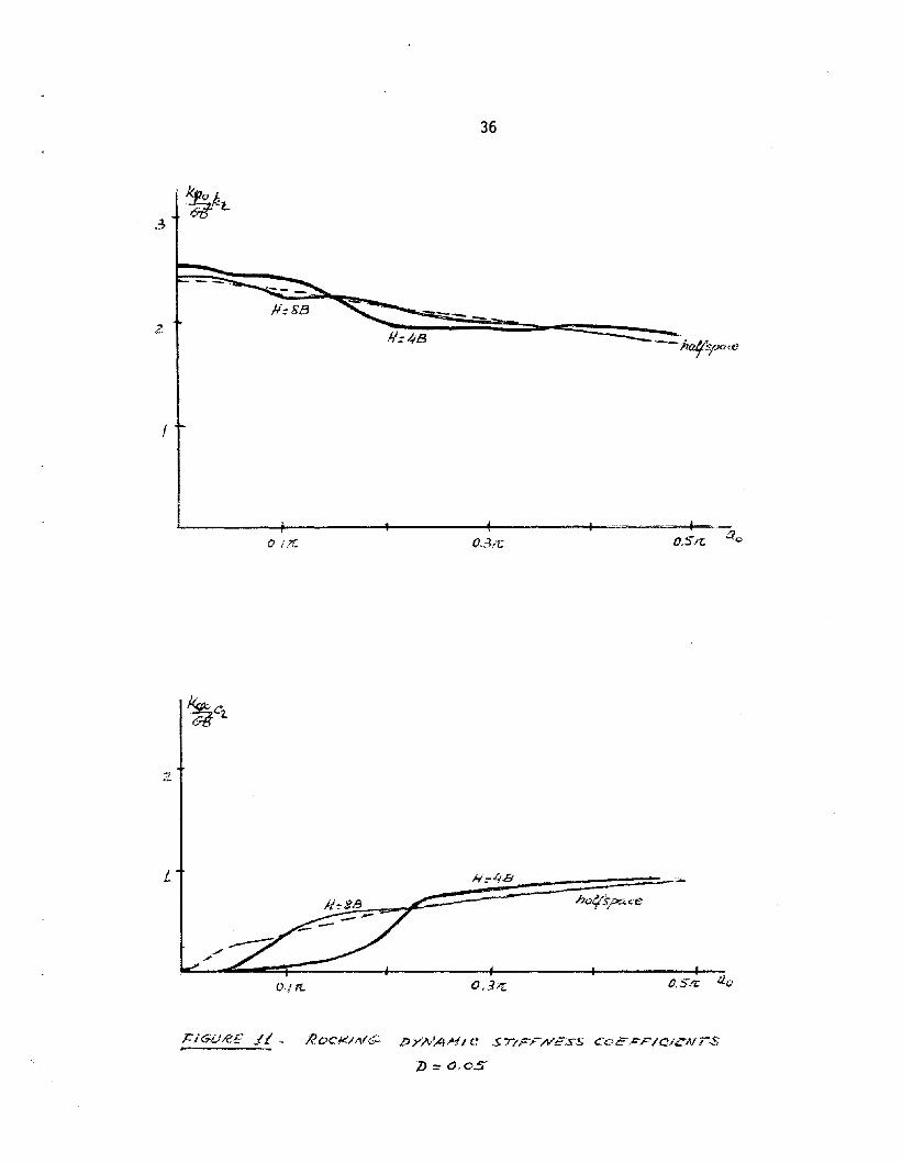
Figures 11 to 13 show the corresponding results for the rocking
c the P wave velocity of the soil and c the shear wavep s
Above this value of a the results are again very similar toohalfspace. The existence of internal soil damping provides for
Kstiffness. The effect of layer depth on the term -~ k? is not very marked,
GB -and for H = 8B the solution is almost identical to that of a halfspace.The effect of increasing the internal damping D is again to reduce theoscillations and to increase the values of k2 in the high frequency range(this increase is only significant for values of D of the order of 0.20 orlarger). If the soil had no internal damping, the complex term ~c? would
GB ~
be zero below the fundamental dilatational frequency of the stratum (ao =c
K~ ~ with2 H Csvelocity).those of a
or
17
nonzero values of c2 below the stratum's natural frequency and a smoothtransition from zero at ao = 0 to the halfspace curve. Notice, however,that in the low frequency range the damping term c2 will always be substantially smaller for a finite soil layer than for a halfspace.
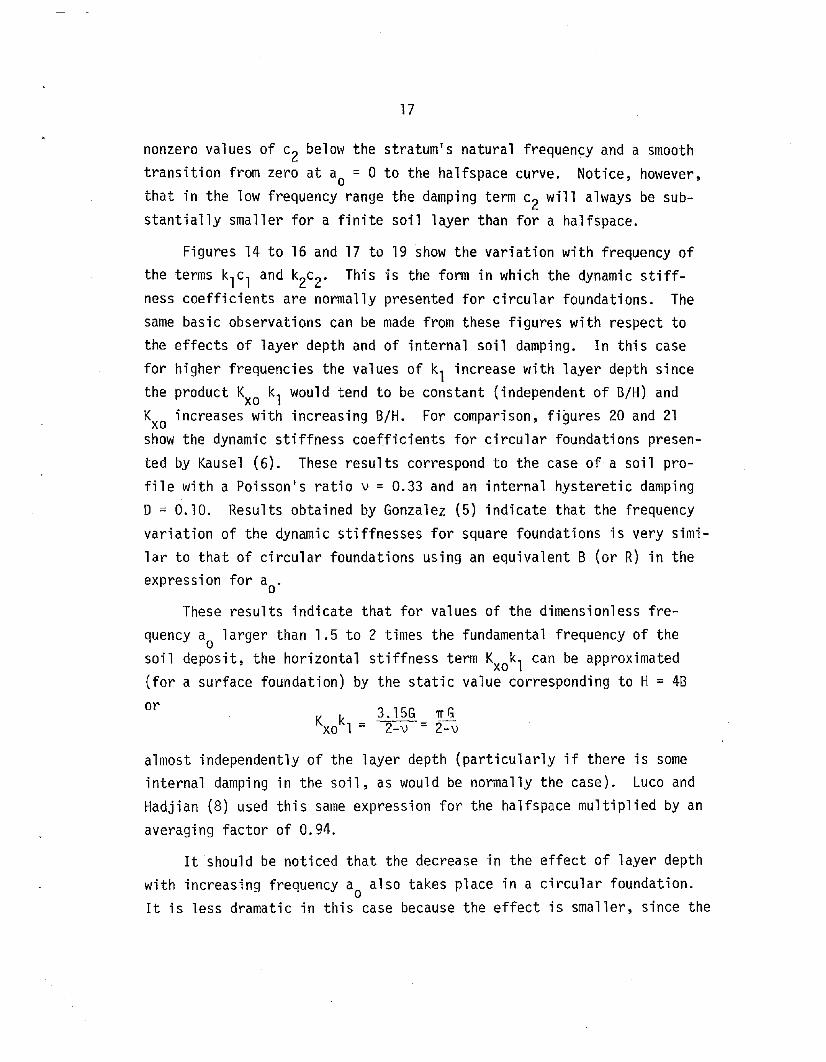
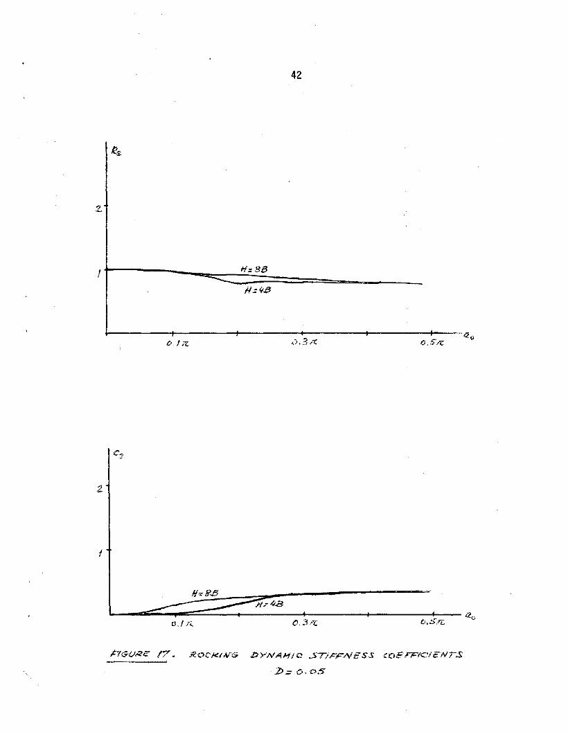
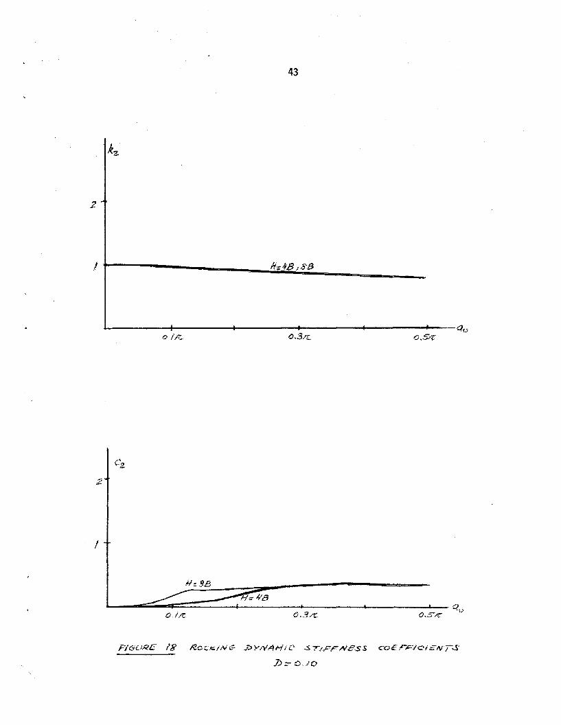
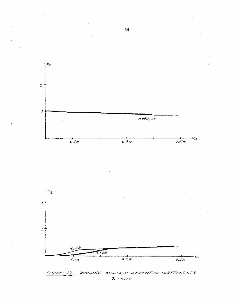
Figures 14 to 16 and 17 to 19 show the variation with frequency ofthe terms klc l and k2c2. This is the form in which the dynamic stiffness coefficients are normally presented for circular foundations. Thesame basic observations can be made from these figures with respect tothe effects of layer depth and of internal soil damping. In this casefor higher frequencies the values of kl increase with layer depth sincethe product Kxo kl would tend to be constant (independent of B/H) andKxo increases with increasing B/H. For comparison, figures 20 and 21show the dynamic stiffness coefficients for circular foundations presented by Kausel (6). These results correspond to the case of a soil profile with a Poisson's ratio v = 0.33 and an internal hysteretic dampingD = 0.10. Results obtained by Gonzalez (5) indicate that the frequencyvariation of the dynamic stiffnesses for square foundations is very similar to that of circular foundations using an equivalent B (or R) in theexpression for ao.
These results indicate that for values of the dimensionless frequencya larger than 1.5 to 2 times the fundamental frequency of the
osoil deposit, the horizontal stiffness term Kxokl can be approximated(for a surface foundation) by the static value corresponding to H = 48
K k 3. 15G 71" Gxo 1 = 2-v = 2-v
almost independently of the layer depth (particularly if there is someinternal damping in the soil, as would be normally the case). Luco andHadjian (8) used this same expression for the halfspace multiplied by an
averaging factor of 0.94.
It should be noticed that the decrease in the effect of layer depthwith increasing frequency ao also takes place in a circular foundation.It is less dramatic in this case because the effect is smaller, since the
18
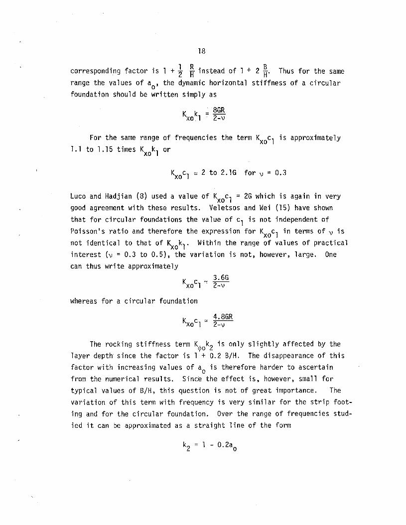
corresponding factor is 1 +} ~ instead of 1 + 2~. Thus for the same
range the values of ao' the dynamic horizontal stiffness of a circularfoundation should be written simply as
K k = 8GRxo 1 2-v
For the same range of frequencies the term Kxoc l is approximately1.1 to 1.15 times K kl orxo
KxoCl ~ 2 to 2.1G for v = 0.3
Luco and Hadjian (8) used a value of KxoCl = 2G which is again in verygood agreement with these results. Veletsos and Wei (15) have shownthat for circular foundations the value of cl is not independent ofPoisson's ratio and therefore the expression for KxoC l in terms of v isnot identical to that of Kxokl . Within the range of values of practicalinterest (v = 0.3 to 0.5), the variation is not, however, large. Onecan thus write approximately
K 3.6Gcl ~ -2-xo . -v
whereas for a circular foundation
The rocking stiffness term K~ k? is only slightly affected by the'/'0 <-
layer depth since the factor is 1 + 0.2 B/H. The disappearance of thisfactor with increasing values of ao is therefore harder to ascertainfrom the numerical results. Since the effect is, however, small fortypical values of B/H, this question is not of great importance. Thevariation of this term with frequency is very similar for the strip footing and for the circular foundation. Over the range of frequencies studied it can be approximated as a straight line of the form
19
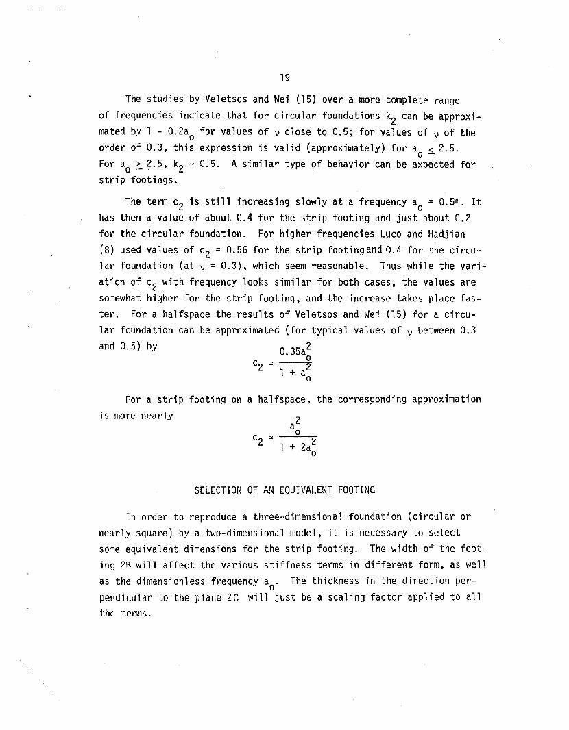
The studies by Veletsos and Wei (15) over a more complete rangeof frequencies indicate that for circular foundations k2 can be approximated by 1 - 0.2ao for values of v close to 0.5; for values of v of theorder of 0.3, this expression is valid (approximately) for a < 2.5.
o -For ao ~ 2.5, k2 ~ 0.5. A similar type of behavior can be expected forstrip footings.
c2 ~ 21 + ao
The term c2 is still increasing slowly at a frequency ao = 0.5TI. Ithas then a value of about 0.4 for the strip footing and just about 0.2for the circular foundation. For higher frequencies Luco and Hadjian(8) used values of c2 = 0.56 for the strip footing and 0.4 for the circular foundation (at v = 0.3), which seem reasonable. Thus while the variation of c2 with frequency looks similar for both cases, the values aresomewhat higher for the strip footing, and the increase takes place faster. For a halfspace the results of Veletsos and Wei (15) for a circular foundation can be approximated (for typical values of v between 0.3
and 0.5) by O.35io
For a strip footing on a halfspace, the corresponding approximation
is more nearly
+ 2a~
SELECTION OF AN EQUIVALENT FOOTING
In order to reproduce a three-dimensional foundation (circular ornearly square) by a two-dimensional model, it is necessary to selectsome equivalent dimensions for the strip footing. The width of the footing 2B will affect the various stiffness terms in different form, as wellas the dimensionless frequency ao. The thickness in the direction perpendicular to the plane 2C will just be a scaling factor applied to allthe terms.

20
For the purpose of estimating the values of the stiffnesses provided by the models, the results of the previous sections can be summarized in the form of the following formulae:
strip footing
with
with
K = 2'rrGC (l + 1 I)(l + .i I)xo 2-\) 3 B 3 H
k1 = ~ (l + 2 ~) for n = 0 (static case)
= 1 for n larger than 1.5 times the naturalshear frequency of the 1a~er. Between thesetwo values of n a transition must be used asshown in figures 8 to 11 or 14 to 16.
c1 = 1.1 for values of n larger than the naturalfrequency of the layer; a transition curvemust be used for lower values of n , dependingon the internal damping D.
K~ = K~o (k2 + i ~: c2}(1 + 2iD)
nGCB2 B E 2 EK = -- (1 + 0.2 -H)(l + -B)(l + -3 -H)¢o 1-\)
k = 1 - 0.2 nB for nB < 2.5 all \)2 c c -s s
= 1 - 0.2 nB for nB > 2.5 \) = 0.45 to 0.5c
scs -
= 0.5 for nB > 2.5 \) = 0.3 to 0.4c -s
a2o with a = nB for n larger than the fun-
+ 2 2 0 Csaodamenta1 dilatational frequency of the layer. For
smaller values of n use a transition curve depending on the internal damping D.
21
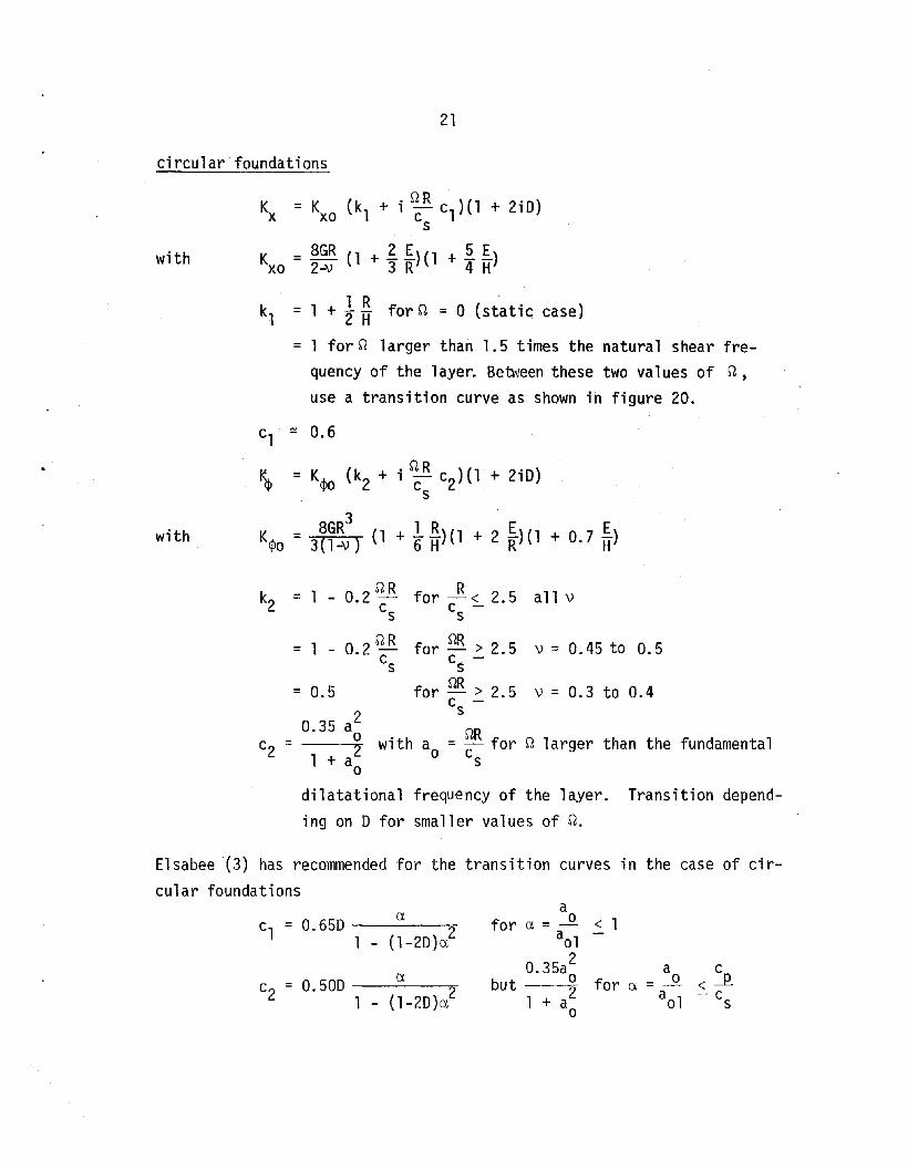
circular foundations
with
Kx = KXO
(kl + i ~: cl)(l + 2iO)
K = 8GR (l + !f)(l + ~~)XO 2-\1 3 R 4 H
kl = 1 + t ~ for n = 0 (static case)
= 1 for n larger than 1.5 times the natural shear frequency of the 1ayer. Be"QI/een these two values of n,use a transition curve as shown in figure 20.
with
cl
~ 0.6
I)p = K<Po (k2 + i ~: c2)(1 + 210)
8GR3 1 R E EKepo = 3(1-v) (l + 6H)(1 + 2 jf)(l + 0.7 iT)
k2 = 1 - 0.2 nR for --R< 2.5 all vCs Cs -
v = 0.3 to 0.4
v = 0.45 to 0.5for nR > 2.5c -snRfor - > 2.5c -s
= 1 - 0.2 nRCs
= 0.5
0.35 a~c2 = with a = cnR for n larger than the fundamental
1 + a~ 0 s
dilatational frequency of the layer. Transition depending on D for smaller values of n.
Elsabee (3) has recommended for the transition curves in the case of circular foundations
ac1 = 0.65D a 0 < 12 for 0.=-
1 (1-20)0. aol2O.35a a c
0.50D a but 0 for a = ....Q. <---.l?.c = 22+ a~ aol -c1 - (1-2D)o. s

22
Similar expressions could be used as a first approximation for thestrip footing, although their applicability was not checked in this study.
As Luco and Hadjian (8) had already pointed out, it is not possibleto select values of footing width and thickness so as to match all thestiffness terms over the complete frequency range. Accounting for a layerof finite depth and embedment complicates the problem further. Even so,it must be recognized that not all the terms have the same effect or importance on the structural response and that some degree of error may betolerated in some of them. In order to assess the validity of a twodimensional model it would be advisable, for each particular problem, toestimate the natural frequency of the soil structure system and the effective amount of damping. These quantities can be computed with variousdegrees of accuracy (and complexity). In the simplest case, if the structure is modelled as an equivalent single-degree-of-freedom system with amass M(or weight w) concentrated at a height h above the base of the foundation, and a spring k such that wo = Ik/M is the fundamental frequencyof the structure on a rigid foundation (without any soil structure interaction effect}, the natural frequency of the combined soil structure sys~
tern can be estimated by
A simple iterative procedure can be used to account for the frequency.
variation of Kxokl and K~ok2.
Once the natural frequency w is known, the effective damping can be
estimated from
(3 = (3 (~) 2+ 0fl - (.~) 21 + 1 wB (i!L) 2 [~_ ~ + --li c2l
o Wo L Wo J 2 Cs Wo Kxokl kl K~ok2 k2Jwhere (3 is the structural damping (assumed to be of a hysteretic nature),o

23
D is the internal soil damping (also hysteretic) and a is the effectivedamping of the combined system. For circular foundations the term wB/csshould be replaced by wR/cs .
By computing wand B using the formulae for both strip footings andcircular foundations, one can determine whether the error introduced bythe two-dimensional approximation will be acceptable for the case considered.
CONCLUSIONS AND RECOMMENDATIONS
A series of parametric studies were conducted to determine the dynamic stiffnesses of strip footings. From the results of these studiesapproximate formulae were derived which were then compared to thosealready available for circular and square foundations. The differencesbetween these formulae are such that important errors may result in somecases when attempting to reproduce a three-dimensional problem by a twodimensional model. Furthermore, it appears that increasing the amountof radiation damping for the strip footing, as done in some pseudo threedimensional solutions, may not improve in general the agreement betweenthe two models. It is therefore recommended that before embarking onthe use of computer programs based on a plane strain model, some preliminary analyses be conducted to assess the magnitude of the errors involvedin this idealization for the particular case under consideration.
24
REFERENCES
1. Berger, E., Lysmer, J. and Seed, H.B., "Comparison of Plane Strainand Axisymmetric Soil Structure Interaction Analysis,'1 2nd ASCESpecialty Conference on Structural Design of Nuclear Plant Facilities, New Orleans, 1975.
2. Chang Li ang, V., "Dynami c Response of Structures in Layered Soil s,"Research Report R74-10, Dept. of Civil Engineering. r'1.I.T., January1974.
3. Elsabee, F. and Morray, J.P., "Dynamic Behavior of Embedded Foundations," Research Report R77-33. Dept. of Civil Engineering, M.I.T.,September 1977.
4. Gazetas, G. and Roesset, J.t4., "Forced Vibrations of Strip Footingson Layered Soils," Proc. National Structures Engineering Conference,ASCE, Madison, Wisconsin, August 1976.
5. Gonzalez, J.J., "Dynamic Interaction between Adjacent Structures,"Research Report R77-30, Dept. of Civil Engineering, M.l.T., September1977 .
6. Kausel, E., "Forced Vibrations of Circular Foundations on LayeredMedia," Research Report R74-11, Dept. of Civil Engineering, M.LT.,January 1974.
7. Kausel, E., Roesset, J.M. and Christian, J. T., "Nonl inear Behaviorin Soil Structure Interaction," Journal of the Geotechnical Engineering Division, ASCE, November 1976.
8. Luco, J.E. and Hadjian, A.H., "Two-Dimensional Approximations to theThree-Dimensional Soil Structure Interaction Problem,'· Nuclear Engineering and Design, 1974.
9. Luco, J. E., "Impedance Functions for a Rigid Foundation on a LayeredMedium,'· Nuclear Engineering and Design, 1974.
10. Lysmer, J., Udaka, T., Seed, H.B. and Hwang, R.N., "LUSH, A ComputerProgram for Complex Response Analysis of Soil Structure Systems,"Report EERC 74-4, University of California, Berkeley, 1974.
11. Lysmer, J., Seed, H.B., Udaka, T., Hwang, R.N. and Tsai, C.F., "Efficient Finite Element Analysis of Seismic Soil Structure Interaction,"Report EERC 75-34, University of California, Berkeley, November 1975.
12. Novak, M.• "Vibrations of Embedded Footings and Structures,'· Preprint2029, ASCE National Structures Engineering Meeting, San Francisco,California, April 1973.
25
13. Novak, M. and Beredugo, Y.O., "The Effect of Embedment on FootingVibrations," Proc. First Canadian Conference on Earthquake Engineering Research, Vancouver, May 1971.
14. Ur1ich, C.M. and Kuh1emeyer, R.L., IICoup1ed Rocking and LateralVibrations of Embedded Footings,1I Canadian Geotechnical Journal,Vol. 10, No.2, May 1973.
15. Veletsos, A.S. And Wei, Y.T., "Lateral and Rocking Vibration ofFootings," Journal of the Soil Mechanics and Foundations Division,ASCE, Vol. 97, September 1971.
16. Ve1etsos, A.S. and Verbic, B., "Vibration of Viscoelastic Foundations," International Journal of Earthquake Engineering and Structural Dynamics, Vol. 2, 1973.
17. Waas, G., "Earth Vibration Effects and Abatement for Military Facilities," Technical Report 571-14, U.S.A.E.W.E.S., September 1972.
18. Wong, H.L., IIDynamic Soil Structure Interaction," Report EERL 75-01,California Institute of Technology, May 1975.

.5
'''I"-
./
,.'"
I /'
26
1..
/='/GUR£ L _ VAR.IATloN OF J/OR..lzo,;yrAL S''-ATtC S~"'IP-~::"NE"SS
WITH t..AYIER. P~Pr"7' - STRIP ~acinNG-
27
5
..,.v:o...3.."
"-'--"---".-..--------- .....- .... -.__ ._..~
2
.3
I
I/z. L
VARIA,ION of ROC.k'IN'C" .,s-rAr/C ST/FFlVtFsS
i,v)'rl-i LA y~~p-' be-porI-! .- S,RIP r--oOTIN'G~
s
5
3
28
1/8
____ J,! :o./'{S
....---_......
• -----------.....- vc:: 0·33•
______---------........ »:::0• •
.!-----+------f---------f--- fUft'18 lUi I/Z
FIGiJ/Ul 3 _ I/ARIATlON' OP S7"ATIC 57IFF/v'f!:S'sFS i.<.fJrr/
LAYC=-R. Dl.Fprfol- CIRC1/LA..«. F"OOIV'PA7irO/V
(ar~ kau.set. ,6)

29
L------------------------.v:O.33
l------------------------------- ,»:0.4$
8
J----------------------- J.l..:"D
1/8
FIG-ORE 4;. VARJArtoN O,c' .,S7A'TIC S7IFFNESSi:S yj'ITH i..,q YER l>CP;~.
SQVAi2E ~OvNDATIOI\I ('o/i:er 6r::wzcde-z./ 5")
.3
,-, fw'... .-
30
1 t::._.::--:.:-:..:-:.::-~-=---::;....::;..----
axnpdec:i v-a/ues
--~}Drvxl.maao~ :2. I2-v
~---___.----------+-----......----l__ tl
.3
I
0·/
..,., dE)GEr{/i<-_ ..,-;'H
02 D.:?; 0.5
/.6-?"l-V
0.5
FIGUP-I.£ S _ VARIATION' OF -$'/;4TIC .5:TIFF/V£~-S£..$
;='O/$$ON /.s RA770 »i,vITi'!
31
3
K)(c
k»co SLV/aCe.
2
I
'------+-----04----------+- BIR~~ IlL; liz
•
C----------------------E""a:; 2/3
Ky:o.3 #ro f,,,r!a•. ,;
1- ----...--------... 5/8 ;:: ~
I
ilLt

32
ofy, .-r
L_-------/'?"'~r-------r::. Ii- 0,3%1
1
.1
FIGURE COt=;FF/C;€NrS FOR. GM8e-DDED FoUNDATIoN'S

33
2
i
o.ilt
,
z
J
o.ln.1o-':;;;;;'-:::::::;;~-+-----~~-----4------t-----+--a.:,
0,3", o.SJ'C
F;C'HJ,P-E }3" f/ol:uzoNT:4t ,P>,WANIC S·TIFFNFSScr..')jF";n:=/ciE/!/TS
l:J ;:;- (). os
3
z
1<.)(0 j..-KiG
34
7- flatff"a,~e
11=-88
o//t o,3x 0.51"(
HOJUZDNTAL z>YN'AH Ie STIFF/Vb-.sS (bEFF/cl(;;~r.s
L:>;;::- v. /0
3
2
35
~Qk- -/G
__ - -- -- ~-Jab'.yxw~_'~_-~_=-=:::._.---- T
l..------f-------ll-------i-------+------t---Qo
3
2
,~xoc. \G (
0.3.,7(. o/Sa
jIII£;~----.....-----+------+-----+------+--- °00.3",1:. O.5n
FIGOl'<e 10 J/ORI"ZoIVTAi... l>YNA#iC STIFF#C:-SS caE,&-;C"/Cy,a-NTS
Z>=O·2.o
.3
36
I
o /,"l: 0.5n::.
L
7J ~ 0.05

3
37
2
i
i
~---.- ~........Idf'¥ace
O.3JC
-------
RaCk!IAlt6.';. 1>'YNA,.41I!C .srIFFNe-sS <::a£F,t"iC;E?/i1r.s/,) ... 0,10

--4;.-
38
--z
I
- -
2
I
o.iJ'C.
#::1,;13"---0";;':';"
........'.....- );<4~~e
Oi/C
ROCkING k>YrVAH/C ...s:rIFFN£S,".; C.::>EFFicieN'TS
7> =0.2D

2
I'
39
1<,
toJ;;;.
2
I
Ct
~r;;E=:::::=--4------4------4------i-----+-_QooJ/[ 0.3/'7:: ().~/z:
FitS-Viet;; ;-t., '" IIOi</~o/llr4/... J.)Y/vA!-fIr:~ ST!FF/YE'SS cuEFFICIt:Nrs:
D= 0.05

40
i-I =8./3
L-_.....;~--......-----+------+--------+------+-41co//L. 0.3<"4 o.Srl" .
......-=:::::..---+------""1-------+-------+-------+-- r.I-eoJy;; {} SIT
Fi60RE IS ~ H<:JRi'2'x.)NTAt... bYAIAMtC -S.7/,cj--N€SS c.o£PFlCiE7v'TS
7) = 0./0

L
41
k.;
L
'-------+-------+-------t'""'-----f-----o+-- q,i;.
.-=------.....-------4--------.....------+----__....._ a ooi;r,:. o.3r7:. D.S/'{.
]) == 0.20
0.17'
42
11------""==:::::::::::I1:::::8~Eh======""'=___._- __j{;iiB
~-----+------+-------t-----+------f---~c~:),3;.-c o,s>"'
2.
I
l-_IIIIIII::.;:::;;;,....-=====----. -+- -+ +-__ tl(>
0.3/<: c.S,?4-
I:"IGf.lRE 17. ROCi<iI,H;: J;>YNAHIC STIFFNESS coEFFICIENTS
1>.= 0.05
2
I
I
43
1J/.:1,f8;8.8
.I-------+------4------+-------+------.....--'1,r,;,
H:..8B
L--...;:;;;:;::;;..:::::::::==::=---<~-=-=----4-------4-------L--Q.'J0.//'-. O.3/t.. O.S.-'t"'
FI60RE /S IeO::"k:ING p'Y/vAH/(.' ST,tFFNESS. coEFFIC'i£N-rS
:J):=- 0,,10
44
2
'r-------------
1.-------+-------+------+-------;------+--c1oo,tf~-r.. o,3n
/'Jk.

45
,k,
/
os
l--------+-------lr--------t-------+--------il----- Cl,;,
j
i.,j~4R.
~__:.:_-_~ - - huf71:s;tr..k<:e----- if;-g~v,s
..1::::::===----+------.....,.------.....------+- -4 'Q1J
0.3;-;;
HOI2i:.-=oN"rAL ST/1-7N'cSS CO£PPlcf5'V'rS
CIR,CVd.AR. p"o~A!b/-l7IoN (alter KaM.set)