Dynamic Scratchpad Memory Management for …ashriva6/teaching/CES/CES_Spring_2008/Dynamic...with =...
38
11 Dynamic Scratchpad Memory Management for Code in Portable Systems with an MMU BERNHARD EGGER Samsung Advanced Institute of Technology JAEJIN LEE and HEONSHIK SHIN Seoul National University In this work, we present a dynamic memory allocation technique for a novel, horizontally parti- tioned memory subsystem targeting contemporary embedded processors with a memory manage- ment unit (MMU). We propose to replace the on-chip instruction cache with a scratchpad memory (SPM) and a small minicache. Serializing the address translation with the actual memory access enables the memory system to access either only the SPM or the minicache. Independent of the SPM size and based solely on profiling information, a postpass optimizer classifies the code of an appli- cation binary into a pageable and a cacheable code region. The latter is placed at a fixed location in the external memory and cached by the minicache. The former, the pageable code region, is copied on demand to the SPM before execution. Both the pageable code region and the SPM are logically divided into pages the size of an MMU memory page. Using the MMU’s pagefault exception mecha- nism, a runtime scratchpad memory manager (SPMM) tracks page accesses and copies frequently executed code pages to the SPM before they get executed. In order to minimize the number of page transfers from the external memory to the SPM, good code placement techniques become more im- portant with increasing sizes of the MMU pages. We discuss code-grouping techniques and provide an analysis of the effect of the MMU’s page size on execution time, energy consumption, and external memory accesses. We show that by using the data cache as a victim buffer for the SPM, significant energy savings are possible. We evaluate our SPM allocation strategy with fifteen applications, including H.264, MP3, MPEG-4, and PGP. The proposed memory system requires 8% less die are compared to a fully-cached configuration. On average, we achieve a 31% improvement in runtime performance and a 35% reduction in energy consumption with an MMU page size of 256 bytes. Categories and Subject Descriptors: C.4 [Performance and Systems]: Design Studies; D.3.4 [Pro- gramming Languages]: Processors—code generation, compilers, optimization; D.4.2 [Operating Systems]: Storage Management—secondary storage, storage hierarchies, virtual memory This work was supported in part by the Ministry of Education under the Brain Korea 21 Project, by ETRI Embedded Software Research Division, and by the IT R&D Program of MIC/IITA (2006- S-040-01, Development of Flash Memory-based Embedded Multimedia Software). ITC at Seoul National University provided research facilities. Authors’ address: Bernhard Egger, Jaejin Lee, and Heonshik Shin, Advanced Compiler Research Laboratory, School of Computer Science and Engineering, Seoul National University, Seoul, 151-744, South Korea. http://aces.snu.ac.kr/; email addresses: [email protected], [email protected]. ac.kr, [email protected]. Permission to make digital or hard copies of part or all of this work for personal or classroom use is granted without fee provided that copies are not made or distributed for profit or direct commercial advantage and that copies show this notice on the first page or initial screen of a display along with the full citation. Copyrights for components of this work owned by others than ACM must be honored. Abstracting with credit is permitted. To copy otherwise, to republish, to post on servers, to redistribute to lists, or to use any component of this work in other works requires prior specific permission and/or a fee. Permissions may be requested from Publications Dept., ACM, Inc., 2 Penn Plaza, Suite 701, New York, NY 10121-0701 USA, fax +1 (212) 869-0481, or [email protected]. C 2008 ACM 1539-9087/2008/02-ART11 $5.00 DOI 10.1145/1331331.1331335 http://doi.acm.org/ 10.1145/1331331.1331335 ACM Transactions on Embedded Computing Systems, Vol. 7, No. 2, Article 11, Publication date: February 2008.
Transcript of Dynamic Scratchpad Memory Management for …ashriva6/teaching/CES/CES_Spring_2008/Dynamic...with =...

11
Dynamic Scratchpad Memory Managementfor Code in Portable Systems with an MMU
BERNHARD EGGER
Samsung Advanced Institute of Technology
JAEJIN LEE and HEONSHIK SHIN
Seoul National University
In this work, we present a dynamic memory allocation technique for a novel, horizontally parti-
tioned memory subsystem targeting contemporary embedded processors with a memory manage-
ment unit (MMU). We propose to replace the on-chip instruction cache with a scratchpad memory
(SPM) and a small minicache. Serializing the address translation with the actual memory access
enables the memory system to access either only the SPM or the minicache. Independent of the SPM
size and based solely on profiling information, a postpass optimizer classifies the code of an appli-
cation binary into a pageable and a cacheable code region. The latter is placed at a fixed location in
the external memory and cached by the minicache. The former, the pageable code region, is copied
on demand to the SPM before execution. Both the pageable code region and the SPM are logically
divided into pages the size of an MMU memory page. Using the MMU’s pagefault exception mecha-
nism, a runtime scratchpad memory manager (SPMM) tracks page accesses and copies frequently
executed code pages to the SPM before they get executed. In order to minimize the number of page
transfers from the external memory to the SPM, good code placement techniques become more im-
portant with increasing sizes of the MMU pages. We discuss code-grouping techniques and provide
an analysis of the effect of the MMU’s page size on execution time, energy consumption, and external
memory accesses. We show that by using the data cache as a victim buffer for the SPM, significant
energy savings are possible. We evaluate our SPM allocation strategy with fifteen applications,
including H.264, MP3, MPEG-4, and PGP. The proposed memory system requires 8% less die are
compared to a fully-cached configuration. On average, we achieve a 31% improvement in runtime
performance and a 35% reduction in energy consumption with an MMU page size of 256 bytes.
Categories and Subject Descriptors: C.4 [Performance and Systems]: Design Studies; D.3.4 [Pro-gramming Languages]: Processors—code generation, compilers, optimization; D.4.2 [OperatingSystems]: Storage Management—secondary storage, storage hierarchies, virtual memory
This work was supported in part by the Ministry of Education under the Brain Korea 21 Project,
by ETRI Embedded Software Research Division, and by the IT R&D Program of MIC/IITA (2006-
S-040-01, Development of Flash Memory-based Embedded Multimedia Software). ITC at Seoul
National University provided research facilities.
Authors’ address: Bernhard Egger, Jaejin Lee, and Heonshik Shin, Advanced Compiler Research
Laboratory, School of Computer Science and Engineering, Seoul National University, Seoul,
151-744, South Korea. http://aces.snu.ac.kr/; email addresses: [email protected],
[email protected]. ac.kr, [email protected].
Permission to make digital or hard copies of part or all of this work for personal or classroom use is
granted without fee provided that copies are not made or distributed for profit or direct commercial
advantage and that copies show this notice on the first page or initial screen of a display along
with the full citation. Copyrights for components of this work owned by others than ACM must be
honored. Abstracting with credit is permitted. To copy otherwise, to republish, to post on servers,
to redistribute to lists, or to use any component of this work in other works requires prior specific
permission and/or a fee. Permissions may be requested from Publications Dept., ACM, Inc., 2 Penn
Plaza, Suite 701, New York, NY 10121-0701 USA, fax +1 (212) 869-0481, or [email protected]© 2008 ACM 1539-9087/2008/02-ART11 $5.00 DOI 10.1145/1331331.1331335 http://doi.acm.org/
10.1145/1331331.1331335
ACM Transactions on Embedded Computing Systems, Vol. 7, No. 2, Article 11, Publication date: February 2008.

11:2 • B. Egger et al.
General Terms: Algorithms, Management, Measurement, Performance, Design, Experimentation
Additional Key Words and Phrases: Code placement, compilers, heterogeneous memory, paging,
portable systems, postpass optimization, scratchpad, victim cache, virtual memory
ACM Reference Format:
Egger, B., Lee, J., and Shin, H. 2008. Dynamic scratchpad memory management for code in portable
systems with an MMU. ACM Trans. Embedd. Comput. Syst. 7, 2, Article 11 (February 2008),
38 pages. DOI = 10.1145/1331331.1331335 http://doi.acm.org/ 10.1145/1331331.1331335
1. INTRODUCTION
Memory systems are typically organized hierarchically with the fastest, mostexpensive, and usually also smallest memory located closest to the CPU, and theslowest, cheapest, and biggest memory farthest from the CPU. Memories likeSRAM provide the necessary speed to feed contemporary CPUs, but they areexpensive. On the other end of the spectrum are hard disks or flash memorythat are cheaper, but an order of magnitude slower than SRAMs. Designinghierarchical memory systems therefore enables system integrators to obtainsatisfactory performance while keeping the manufacturing cost reasonable.
The memory closest to the CPU, so-called level-one, or L1-memory, is usu-ally either implemented as a hardware cache or as scratchpad memory (SPM).Hardware caches automatically store frequently used data on an on-demandbasis. Whenever the CPU requests a datum, the hardware cache first checkswhether it already has the datum stored. If yes, the datum is returned to theCPU (cache hit), typically with one cycle latency. If not, a cache miss has oc-curred, and the cache requests the datum from the next level in the memoryhierarchy. The latency of a cache miss in embedded systems is usually an or-der of magnitude slower than a cache hit. Scratchpad memories, on the otherhand, are software managed. That is, the operating system, or the programmerdecide what data should be copied to the SPM or written back to the externalmemory at what points in the course of the application. Compared to a cacheof the same size, scratchpad memories not only require less die area, but alsoconsume significantly less energy [Panda et al. 1997; Banakar et al. 2002].
Despite scratchpad memories’ advantages, L1-memory is usually imple-mented as a hardware cache in desktops and contemporary high-end embed-ded CPUs, such as Intel’s XScale processor [Intel XScale 2002]. There are twomain reasons for this: first, to run an application efficiently on a cached ar-chitecture, little or no information about the application’s behavior is neces-sary. The cache management logic automatically stores recently used data inthe cache. The data remains in the cache until it gets replaced by more re-cent data, i.e., a cache automatically adapts to the application course. This isin contrast to the SPM, where profiling data about frequently executed codeblocks and/or frequently accessed data must be obtained and analyzed beforean SPM-optimized binary can be generated that achieves similar or even bet-ter performance on a SPM-equipped core than on a cached core. Second, bi-nary compatibility is an important property for applications that run on vari-ous hardware configurations. However, with very few exceptions [Egger et al.2006b; Nguyen et al. 2005], dynamic (and especially static) SPM allocation
ACM Transactions on Embedded Computing Systems, Vol. 7, No. 2, Article 11, Publication date: February 2008.

Dynamic Scratchpad Memory Management for Systems with an MMU • 11:3
techniques require the SPM size to be known at compile-time in order to com-pute the optimal SPM allocation. That is, to accommodate for the various con-figurations of cores and SPM sizes, application vendors have to produce severaldifferent SPM-optimized binaries to cover all possible configurations. This isnot only cumbersome, but also complicates the installation process for the enduser.
In embedded systems, on the other hand, the use of scratchpad memory iswidespread. Some examples of processors with SPM are ARMv6 cores [2002],the Intel IXP Network Processor [2002], Intel’s XScale [2002], or Phillips’LPC3180 microcontroller [2006]. Embedded systems often serve a specific pur-pose. Software is configured and installed on the device before it ships; it israrely changed thereafter. This allows designers to customize embedded appli-cations to a particular configuration and take full advantage of the SPM. Con-temporary portable devices, however, are getting more powerful and includean increasing number of features. While just a couple of years ago tech-savvyconsumers had to carry around a mobile phone, an MP3 player, a PDA, anda portable TV, these days it is hard to find a phone without a built-in digitalcamera, MP3 player, personal organizer, and dozens of other features. Unliketraditional embedded systems, users can download and run applications thathave been built without a specific hardware configuration in mind. In otherwords, binary portability is also becoming increasingly important for embed-ded systems.
In this work, we present a dynamic memory allocation technique for a novel,horizontally partitioned memory subsystem targeting portable devices. Theon-chip instruction cache is replaced by an SPM and a small minicache. Be-cause of the significantly lower die are requirements of SPM compared to cache[Banakar et al. 2002], the proposed design does not occupy additional die area.The SPM is physically addressed and mapped into the virtual address space.During the MMU’s virtual-to-physical address translation, the affected memorystructure is determined. By serializing the address translation with the actualmemory access, the memory system accesses either the SPM or the minicache,which saves a considerable amount of energy.
A postpass optimizer is used to generate application binaries optimized forthe proposed memory system. Independent of the SPM size and based solelyon profiling information, it classifies the code of an application binary into apageable and a cacheable code region. The former is copied on demand to theSPM before execution. The latter, the cacheable code region, is placed at a fixedlocation in the external memory and cached by the minicache. Since the codeclassification is independent of the SPM size, the generated SPM-optimizedbinaries are portable across varying hardware configurations.
We introduce a runtime scratchpad memory manager (SPMM) that trackspage accesses using the MMU’s pagefault exception and copies frequently exe-cuted code pages to the SPM before they get executed. Both the pageable coderegion and the SPM are logically divided into pages the size of one MMU mem-ory page. When a new process is created, the runtime SPMM sets up the pro-cess’ virtual-to-physical page table mappings. Main memory cacheable code isplaced in cacheable memory regions. Pageable code resides in the main memory,
ACM Transactions on Embedded Computing Systems, Vol. 7, No. 2, Article 11, Publication date: February 2008.

11:4 • B. Egger et al.
but is copied on-demand to the SPM before execution. The SPMM contains athrashing protection heuristic to prevent thrashing if the working set is largerthan the available SPM.
In order to minimize the number of page transfers from the external mem-ory to the SPM, good code placement techniques become more important withincreasing sizes of the MMU pages. The postpass optimizer identifies loops andgroups temporally local code into the as few pages as possible to minimize thenumber of pages in the working set.
The contributions of this paper are as follows. First, we introduce a dynamicSPM allocation technique that loads pages on demand. Thus, our approachis independent of the SPM size. The SPM-optimized binaries generated by ourpostpass optimizer are binary portable across various hardware configurations.At runtime, thrashing protection heuristics ensure that the applications runefficiently even for smaller SPM sizes.
Second, we propose a horizontally partitioned memory system for contempo-rary embedded processors with an MMU. The instruction cache is replaced bya direct-mapped, physically addressed minicache and scratchpad memory withone-cycle access latency supporting CPU clock frequencies of up to 1 GHz. Thepresence of the minicache enables SPM-unaware programs to run with rea-sonable performance. To the best of our knowledge, this work, along with ourpreliminary results [Egger et al. 2006b], presents the first approach to accessphysically addressed SPM in a virtual memory environment.
Third, by using a postpass optimizer, we are able to generate SPM-optimizedbinaries to which the source code is not readily available. Unlike previouswork, the SPM-optimized binaries run unmodified with almost no performancedegradation on systems without any SPM. We, therefore, achieve total memoryarchitecture independence: SPM-optimized application binaries run on pro-cessors with or without SPM, and the proposed memory architecture runsSPM-optimized as well as SPM-unaware binaries.
Last, we show that by using the data cache as a victim buffer for the SPM,considerable additional energy savings are possible. We provide an in-depthanalysis of the effect of the MMU’s page size on our dynamic SPM managementtechnique. We find that with an MMU page size of 256 bytes, on average, weachieve a 8% reduction in die area consumption, a 31% improvement in runtime,and a 35% reduction in energy consumption.
We implemented the proposed horizontally partitioned memory subsystemin our cycle-accurate ARM9E-S core simulator [SNACK 2004]. To evaluate ourapproach, we used an H.264 video decoder, the standard ISO MP3 decoder,an MPEG-4 video encoder/decoder, a public-key encryption/decryption program(PGP), and several applications from MediaBench [Lee et al. 1997] and MiBench[Guthaus et al. 1998].
The rest of this paper is organized as follows. Section 2 describes the mem-ory architecture of our system. Section 3 presents the runtime SPM manager.Section 4 describes in detail the postpass optimizer and our code place-ment technique. Section 5 explains the evaluation environment, and Section 6presents our experimental results. Section 7 summarizes related work.Section 8 concludes the paper.
ACM Transactions on Embedded Computing Systems, Vol. 7, No. 2, Article 11, Publication date: February 2008.
Dynamic Scratchpad Memory Management for Systems with an MMU • 11:5
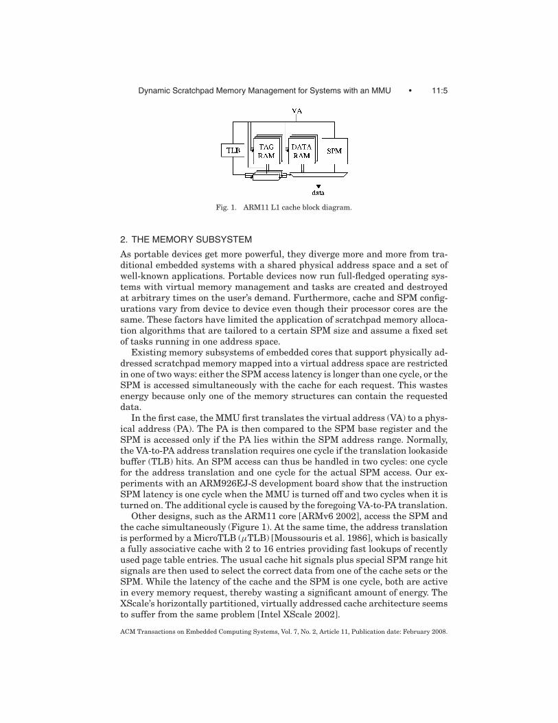
Fig. 1. ARM11 L1 cache block diagram.
2. THE MEMORY SUBSYSTEM
As portable devices get more powerful, they diverge more and more from tra-ditional embedded systems with a shared physical address space and a set ofwell-known applications. Portable devices now run full-fledged operating sys-tems with virtual memory management and tasks are created and destroyedat arbitrary times on the user’s demand. Furthermore, cache and SPM config-urations vary from device to device even though their processor cores are thesame. These factors have limited the application of scratchpad memory alloca-tion algorithms that are tailored to a certain SPM size and assume a fixed setof tasks running in one address space.
Existing memory subsystems of embedded cores that support physically ad-dressed scratchpad memory mapped into a virtual address space are restrictedin one of two ways: either the SPM access latency is longer than one cycle, or theSPM is accessed simultaneously with the cache for each request. This wastesenergy because only one of the memory structures can contain the requesteddata.
In the first case, the MMU first translates the virtual address (VA) to a phys-ical address (PA). The PA is then compared to the SPM base register and theSPM is accessed only if the PA lies within the SPM address range. Normally,the VA-to-PA address translation requires one cycle if the translation lookasidebuffer (TLB) hits. An SPM access can thus be handled in two cycles: one cyclefor the address translation and one cycle for the actual SPM access. Our ex-periments with an ARM926EJ-S development board show that the instructionSPM latency is one cycle when the MMU is turned off and two cycles when it isturned on. The additional cycle is caused by the foregoing VA-to-PA translation.
Other designs, such as the ARM11 core [ARMv6 2002], access the SPM andthe cache simultaneously (Figure 1). At the same time, the address translationis performed by a MicroTLB (μTLB) [Moussouris et al. 1986], which is basicallya fully associative cache with 2 to 16 entries providing fast lookups of recentlyused page table entries. The usual cache hit signals plus special SPM range hitsignals are then used to select the correct data from one of the cache sets or theSPM. While the latency of the cache and the SPM is one cycle, both are activein every memory request, thereby wasting a significant amount of energy. TheXScale’s horizontally partitioned, virtually addressed cache architecture seemsto suffer from the same problem [Intel XScale 2002].
ACM Transactions on Embedded Computing Systems, Vol. 7, No. 2, Article 11, Publication date: February 2008.

11:6 • B. Egger et al.
Fig. 2. On-chip memory architecture.
Fig. 3. Each TLB entry contains an additional SPM flag.
2.1 Horizontally Partitioned Memory Subsystem
Egger et al. [2006b] have proposed a horizontally partitioned, on-chip memorysubsystem for the instruction side of a Harvard architecture (Figure 2). Theoriginal instruction cache is replaced by an SPM and a minicache. Both theSPM and the minicache are physically addressed. The address translation isserialized with the SPM/minicache access. The resulting PA is compared to theSPM base register to decide which of the memories, the SPM, the minicache,or the external memory should be accessed. The serialization of the addresstranslation and the SPM/minicache access enables the memory system to fetchthe datum from the correct memory, eliminating the unnecessary duplicatedmemory access mentioned above.
In this paper, we propose an improvement to the aforementioned horizontallypartitioned memory architecture (Figure 3). In [Egger et al. 2006b], the SPMbase register comparison, performed by a 32-bit comparator, is serialized withthe TLB access. The outcome of the comparison is, however, always the samefor a given physical address of an entry in the μTLB (unless, of course, the SPMbase register is modified). We can, therefore, move the 32-bit comparator awayfrom the time critical path into the MMU’s VA-to-PA translation and only storethe result of the comparison in an additional bit in each TLB entry. We call thisbit the SPM flag.
When fetching an instruction, the μTLB first looks up the VA of the instruc-tion. The SPM flag stored in the selected TLB entry determines whether thedatum is to be loaded from the SPM or the minicache (Figure 3). If the SPM flagis set, the PA is located in the SPM address range, and only the SPM is accessedto retrieve the datum. If the SPM flag is clear, then the datum must be loadedfrom the minicache, in which case the SPM is not accessed. Since the SPMflag is evaluated inside the μTLB along with the VA-PA address pairs, it ren-ders the time- and energy-wise more expensive full 32-bit address comparison
ACM Transactions on Embedded Computing Systems, Vol. 7, No. 2, Article 11, Publication date: February 2008.

Dynamic Scratchpad Memory Management for Systems with an MMU • 11:7
Table I. Cycle Access Time
8-entry μTLB 0.22ns
16KB SPM 512B direct-mapped cache 0.35ns 0.21ns
Total latency (μTLB → SPM or minicache) 0.57ns
Table II. Die Area Requirements of the Horizontally Partitioned Memory Subsystem Compared
to Various Instruction Cache Sizes
Cache SPM Minicache Total
Area Size Area Size Area Area Die Area
Configuration [mm2] [KB] [mm2] [B] [mm2] [mm2] Reduction (%)
1KB, 4-way, 16B lines 0.37 3 0.22 512 0.10 0.32 13
2KB, 4-way, 32B lines 0.42 4 0.29 512 0.10 0.39 7
4KB, 4-way, 32B lines 0.53 6 0.39 512 0.10 0.49 8
8KB, 4-way, 32B lines 0.73 10 0.60 512 0.10 0.70 4
unnecessary. The SPM flag is computed by the MMU for each address trans-lation. Therefore, the entries of the unified TLB must also contain the SPMflag.
Compared to a traditional cache, serializing the address translation with theSPM or cache access increases the latency of an instruction fetch by approxi-mately the access time of the μTLB. With the current 0.13-μm manufacturingprocess, however, core clocks of up to 1 GHz can easily be supported with a one-cycle latency. Table I shows cycle access times (i.e., the minimal time betweentwo subsequent requests) for both μTLB, cache, and scratchpad memories. Thenumbers were obtained with CACTI [Wilton and Jouppi 1996].
Because of the missing cache control logic and the simpler design, scratchpadmemories are more efficient than caches in terms of both energy and die area.We can, therefore, replace the cache with scratchpad memory that is largerthan the original cache and add a 512-byte minicache, yet still achieve a reduc-tion in the required die area. Table II lists the configuration of our proposedhorizontally partitioned memory system for various cache sizes.
For example, a 4-KB, 4-way set associative cache with a line size of 32 bytesoccupies a die area of 0.53 mm2. Replacing the 4-KB cache with a 6-KB SPM(0.39 mm2) plus a 512-B direct-mapped cache with a line size of 16 bytes(0.10 mm2) requires a die area of only 0.49 mm2, or 8% less than the cache.
Note that only the instruction cache is replaced by an SPM and a minicache.We do not modify the data side of the L1-memory hierarchy.
Unlike a cache, a scratchpad memory is not managed by hardware. Instead,the runtime system is responsible for its contents and efficient utilization. Thisis the subject of the next section.
3. SPM MANAGEMENT
In this section, we briefly describe the runtime system that we have introducedin [Egger et al. 2006b]. On cached cores, binaries run without further softwaresupport. On cores equipped with scratchpad memory, however, the SPM has tobe explicitly managed either by the running application or by a dedicated SPMmanager that is part of the runtime environment.
ACM Transactions on Embedded Computing Systems, Vol. 7, No. 2, Article 11, Publication date: February 2008.

11:8 • B. Egger et al.
Fig. 4. Data structures and virtual memory organization of SPM-optimized binaries.
For embedded systems, the set of running tasks and the size of the SPM areoften known when the system is built. For such systems, particularly well-suitedSPM management techniques are those where the optimal storage location ofeach code and/or data block is solved by an integer linear programming (ILP)formulation and the SPM is managed by the running task. These techniques,however, have the disadvantage that the optimized binaries are tailored toexactly one hardware configuration, and might run only inefficiently (or not atall) on different configurations.
To overcome this problem, we propose an SPM management technique thatdepends neither on a certain size of the SPM nor on a predetermined set of run-ning applications. We have implemented our technique into a minimal runtimeenvironment. Our scratchpad memory manager (SPMM) manages the SPM atruntime as a global resource. The SPMM uses demand-paging techniques simi-lar to those in virtual memory systems [Fotheringham 1961] to track the courseof the application and load pages into the SPM on demand.
3.1 SPM-Optimized Binaries
Our postpass optimizer (see Section 4) generates the SPM-optimized binaries.It extracts frequently executed code sections from the code and groups themtogether into the pageable code region. The infrequently executed code is placedin the cacheable region. The pageable region is logically divided into pagesthe size of an MMU memory page. The postpass optimizer detects loops (seeSubsection 4.3) and clusters their code together into as few pages as possibleto minimize the working set [Denning 1967].
An SPM-optimized binary contains additional information that allows theSPMM to setup the MMU’s page table mappings when the binary is first loaded.Specifically, the postpass optimizer stores two additional data structures in thebinary, the region table and the block table (Figure 4). The region table contains
ACM Transactions on Embedded Computing Systems, Vol. 7, No. 2, Article 11, Publication date: February 2008.

Dynamic Scratchpad Memory Management for Systems with an MMU • 11:9
the location and size of both the pageable and cacheable region. The block tablecontains one entry per pageable block. Each entry contains the block’s size, itsloop block index (LBI), the virtual address of the block, and the address of thepage table entry (PTE) in the second level pagetable. Because of fragmentation,some blocks might not be completely filled. Hence, the size field allows theSPMM to copy only as many bytes as needed. The address of the PTE andthe virtual address of each block are computed by the SPMM at load-time andstored in the block table. The loop block index of block bk is defined as the pairlbi(bk) =< l , i >. The loop index l denotes to which loop block bk belongs, andthe block index i denotes the index of block bk within loop l . The LBI is requiredfor the thrashing protection heuristics (Section 3.2). In Figure 4, blocks b1 andb2 both belong to loop 1 with b1 being the first block, and b2 the second block ofloop 1. The second loop, loop 2, consists of the blocks b4, b5, and b3 (in this order).
3.2 Runtime SPM Management
When a binary image is loaded, the runtime SPMM tries to find the regiontable. If no region table is present, the image is not an SPM-optimized binaryand all code sections are mapped cacheable. If the region table can be found, thecacheable region is mapped to cacheable memory region, whereas the pageableregion remains unmapped, i.e., accessing any datum in this region will triggeran MMU page fault. The global heap and stack are mapped to a cacheablememory regions; accesses to heap or stack are covered by the data cache (ifpresent). The SPMM computes and stores the addresses of the PTEs in the pagetables and each block’s virtual address in the block table. Figure 4 displays apossible memory allocation after loading an SPM-optimized binary. The cachedand the pageable region have been mapped to virtual addresses 0x200, and0x800, respectively. The addresses of the five pageable blocks are stored inthe block table along with their PTE addresses (shown in italic). The pageableregion contains two loops. Loop 1 consists of two, and loop 2 of three blocks(denoted < 01, 01 >, < 01, 02 >, and < 02, 01 >, < 02, 02 >, < 02, 03 >,respectively).
After the binary has been loaded and the page tables have been setup, theapplication starts running. As soon as the program counter (PC) reaches codelocated in the paged region, the memory access fails because the memory is notmapped. The MMU signals a pagefault exception to the CPU, which then con-tinues execution in the pagefault execution handler (Figure 5c(1)). The SPMM,intercepting the pagefault exception, determines in which page the the faulthas occurred, and copies that page to the SPM (Figure 5c(2)). It then modifiesthe PTE and restarts the aborted instruction (Figure 5d(3+4)). The code nowruns without further interruption until the PC reaches another disabled mem-ory page. It is worthwhile noting that as long as a page remains in the SPM, itsPTE remains valid and entering that page will not generate a pagefault, i.e.,no additional cost occurs when the course of the application reaches an alreadyloaded page.
Usually, the number of pages in the paged code region exceeds the number ofavailable pages in the SPM. Therefore, pages residing in the SPM may need to
ACM Transactions on Embedded Computing Systems, Vol. 7, No. 2, Article 11, Publication date: February 2008.

11:10 • B. Egger et al.
Fig. 5. Operation of the SPM manager.
be evicted before a new page can be loaded into the SPM. Since code pages areread-only, the SPMM does not need to copy the page back to main memory; itsimply overwrites the old page with the contents of the new one. The PTE of theevicted page has to be invalidated, however, to trigger invocation of the SPMMas soon as that page is accessed again. For this purpose, the SPMM keeps trackof which pages in the SPM are occupied and which pages are free. The SPMMuses a round-robin policy for page replacement.
3.2.1 Thrashing-Protection Heuristics. The postpass optimizer classifiescode into pageable and cacheable regions independent of the actual SPM size.Thrashing occurs if the working set of pageable blocks exceeds the number ofblocks available in the SPM. The SPMM contains a simple thrashing-protectionheuristics: The working set of a loop consists of all pageable blocks of that loop.The information which block belongs to which loop is stored in the block table’sLBI field. To protect the application from thrashing while executing a loop,
ACM Transactions on Embedded Computing Systems, Vol. 7, No. 2, Article 11, Publication date: February 2008.

Dynamic Scratchpad Memory Management for Systems with an MMU • 11:11
Fig. 6. The postpass optimizer.
the SPMM maps all blocks bk where the block index i in lbi(bk) =< l , i > islarger than NSPM, the number of SPM pages, to the minicache. This reducesthe number of pages, or the working set, of the loop to the size of the SPM. If theloop does not contain any inner loops, this heuristics protects the applicationfrom thrashing.
Our demand-paging technique is independent of the SPM size and directlyapplicable to multiple tasks. Since all addresses are virtual addresses, no codepatching is necessary. An SPMM-enabled application runs just as well as anunmodified binary on a cached-only architecture.
To achieve optimal performance, the pageable code region should containonly code that is worth being copied to the SPM before execution. In an unmod-ified application binary, frequently executed code is randomly spread over thewhole binary image. The next section discusses in more detail our postpass op-timizer and how it modifies the binary to achieve optimal results in conjunctionwith the SPM manager.
4. THE POSTPASS OPTIMIZER
4.1 Overview
Using a postpass optimizer has several advantages. First, any binary can beoptimized for our scratchpad-allocation technique without requiring access tothe source code and recompiling the application. Second, a postpass optimizerenables whole program optimization, including libraries, which is impossibleat the source level. Finally, since optimizations concerning code layout are of arather low-level nature, postpass code arrangement is well-suited for this pur-pose. Figure 6 shows the organization of our postpass optimizer called SNACK-pop. SNACK-pop is part of our Seoul National University Advanced Compilertool Kit [SNACK 2004]. It operates on the ARM/Thumb instruction set,including the DSP extensions.
ACM Transactions on Embedded Computing Systems, Vol. 7, No. 2, Article 11, Publication date: February 2008.

11:12 • B. Egger et al.
Fig. 7. Constant data extraction from local constant pools.
The inputs to our postpass optimizer are application binaries and librariesin the ARM ELF file format. SNACK-pop disassembles the object files into codeand data segments and resolves all undefined symbols. In the next step, the codeblocks are further divided into functions composed of basic blocks. Brancheswith hard-coded offsets are resolved and replaced by relocation information toenable SNACK-pop to freely relocate code.
4.1.1 Constant Data. Constant data residing in local data pools requiresspecial attention. Most ARM compilers place constant data used in a functioninto the function’s constant pool. Consider, for example, a function foo() thatcontains a call to the strcmp() string comparison function with one of the stringshard-coded in the source. The string is placed into foo’s constant pool, which isincluded in foo’s code segment (Figure 7a). One of the arguments to strcmp()is a pointer to the constant string and is generated by adding the offset fromthe current PC to the first character of the embedded string. Now imagine thatboth foo() and strcmp() are located in the pageable code region, but not in thesame page. If the SPM is full and the call to strcmp() causes the SPMM to loadthe page containing strcmp() into the SPM, foo’s page might get evicted. Sincestrcmp() contains a reference to foo’s constant pool, the access of this data wouldbe aborted immediately, causing foo’s page to be reloaded. Excessive thrashingcould result in extreme cases when only few SPM pages are available.
To avoid such scenarios, whenever SNACK-pop detects the passing of point-ers that point to a function’s constant pool, it extracts the referenced constantdata from the function and places it in a global data region that is not pageable.The call is then modified to pass a pointer to the global data. (Figure 7b).
4.1.2 PC-Relative Data Table Accesses. Data accesses to tables using PC-relative addressing also require special care, because the offset between theinstruction accessing the data and the data itself must remain constant. Thishinders free relocation of basic blocks and data blocks. An example of such atable access is shown below
0x20 add r0, pc, #0x18 ; = 0x400x24 ldrb r2, [r0, . . . ]
. . .
. . .
. . .
ACM Transactions on Embedded Computing Systems, Vol. 7, No. 2, Article 11, Publication date: February 2008.
Dynamic Scratchpad Memory Management for Systems with an MMU • 11:13
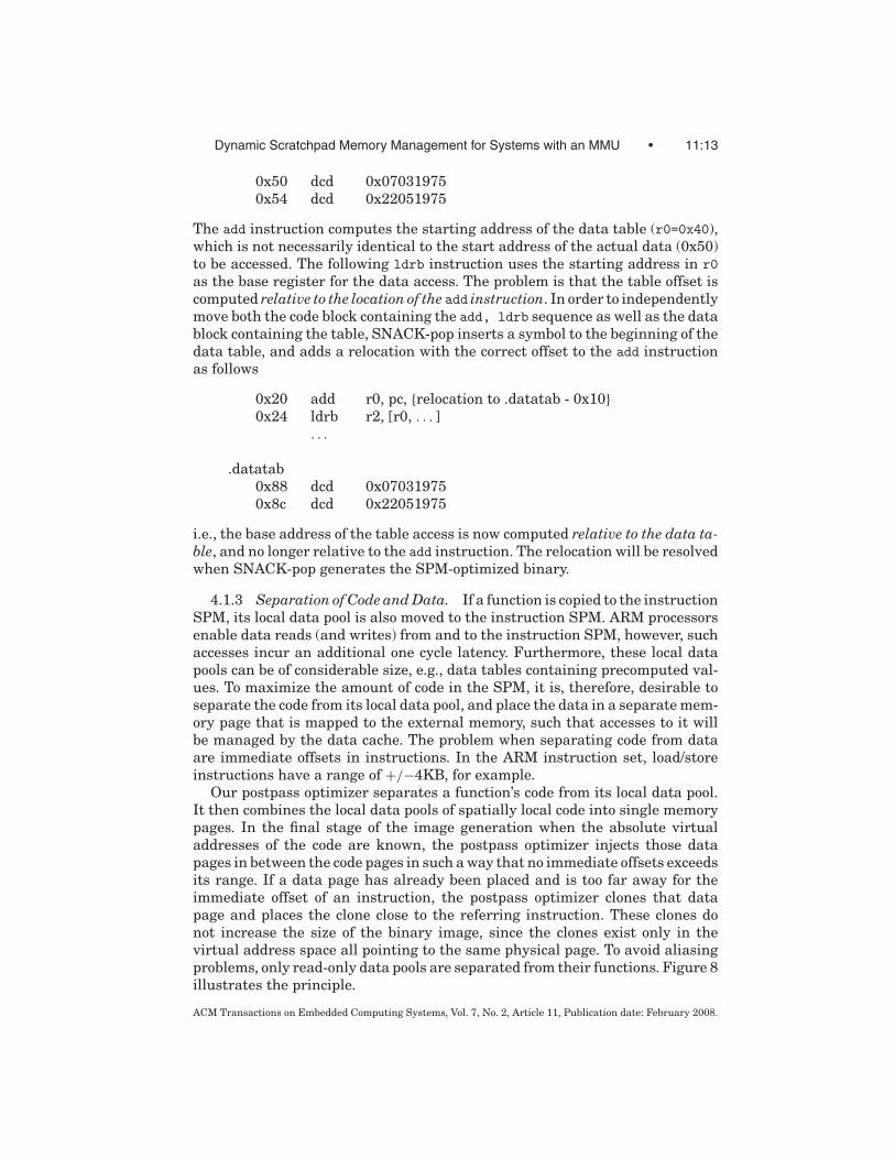
0x50 dcd 0x070319750x54 dcd 0x22051975
The add instruction computes the starting address of the data table (r0=0x40),which is not necessarily identical to the start address of the actual data (0x50)to be accessed. The following ldrb instruction uses the starting address in r0as the base register for the data access. The problem is that the table offset iscomputed relative to the location of the add instruction. In order to independentlymove both the code block containing the add, ldrb sequence as well as the datablock containing the table, SNACK-pop inserts a symbol to the beginning of thedata table, and adds a relocation with the correct offset to the add instructionas follows
0x20 add r0, pc, {relocation to .datatab - 0x10}0x24 ldrb r2, [r0, . . . ]
. . .
.datatab0x88 dcd 0x070319750x8c dcd 0x22051975
i.e., the base address of the table access is now computed relative to the data ta-ble, and no longer relative to the add instruction. The relocation will be resolvedwhen SNACK-pop generates the SPM-optimized binary.
4.1.3 Separation of Code and Data. If a function is copied to the instructionSPM, its local data pool is also moved to the instruction SPM. ARM processorsenable data reads (and writes) from and to the instruction SPM, however, suchaccesses incur an additional one cycle latency. Furthermore, these local datapools can be of considerable size, e.g., data tables containing precomputed val-ues. To maximize the amount of code in the SPM, it is, therefore, desirable toseparate the code from its local data pool, and place the data in a separate mem-ory page that is mapped to the external memory, such that accesses to it willbe managed by the data cache. The problem when separating code from dataare immediate offsets in instructions. In the ARM instruction set, load/storeinstructions have a range of +/−4KB, for example.
Our postpass optimizer separates a function’s code from its local data pool.It then combines the local data pools of spatially local code into single memorypages. In the final stage of the image generation when the absolute virtualaddresses of the code are known, the postpass optimizer injects those datapages in between the code pages in such a way that no immediate offsets exceedsits range. If a data page has already been placed and is too far away for theimmediate offset of an instruction, the postpass optimizer clones that datapage and places the clone close to the referring instruction. These clones donot increase the size of the binary image, since the clones exist only in thevirtual address space all pointing to the same physical page. To avoid aliasingproblems, only read-only data pools are separated from their functions. Figure 8illustrates the principle.
ACM Transactions on Embedded Computing Systems, Vol. 7, No. 2, Article 11, Publication date: February 2008.

11:14 • B. Egger et al.
Fig. 8. Separating local data pools from code. (a) Original functions with local data pools (b) after
separating the local data pools from their functions and grouping code and data independently into
pages. (c) When placing the code, data pages are inserted (and cloned), as necessary, in such a way
that all references can be resolved.
4.1.4 Workflow. To generate an SPMM-optimized binary, SNACK-pop firstinserts instrumentation code into each function and basic blocks to gather pro-filing information. The profiling image is run on an instruction set simulator(ISS) to get the call/return profile. The unmodified reference image is also run toobtain a trace of all instruction fetches during the execution of the application.Several profiles and instruction traces are generated with different traininginput sets.
In a second step, those profiles are again fed into SNACK-pop to generate anSPM-optimized binary. SNACK-pop computes the average number of instruc-tion fetches for each basic block. For each block, the energy model describedin the following section is solved and the basic block is assigned to either thepaged, or the cached code region. This process is described in greater detailin Section 4.3. Once the code placement is done, SNACK-pop generates a newELF binary and inserts the data structures required by the SPM manager (theregion table and the block table, see Section 3.1) that contain the location andsize of of the two code regions paged and cached, as well as additional infor-mation on the paged region. When loading an ELF binary, the SPMM managersearches the image for these data structures. If they are present, the memorymappings are setup accordingly. If not, the image is an unoptimized image andthe entire code is mapped cacheable.
4.2 Code Classification
Based on the trace profile, SNACK-pop determines the code region for eachblock bi using the following heuristics:
Loci ={
cached if Ecached(bi) < Epaged(bi)
paged otherwise
ACM Transactions on Embedded Computing Systems, Vol. 7, No. 2, Article 11, Publication date: February 2008.

Dynamic Scratchpad Memory Management for Systems with an MMU • 11:15
with
Epaged(bi) = Ai · espm + M · Si(eext + espm) (1)
Ecached(bi) = Ai · ecache(1 + mcache · linesize) (2)
where
Ai number of instructions fetched from block bi
Si size of block bi in wordsM average number of page missesmcache cache miss ratioespm SPM access energy per instructioneext external memory access energy per instructionecache cache access energy per instructionlinesize linesize of the cache
The first term in Eq. (1), Ai · espm, represents the energy required to executeblock bi from the SPM. The second term, M · Si(eext + espm), computes the costof copying block bi from main memory to the SPM. The empirical factor M isused to consider the fact that a block might get copied to the SPM several times.Note that we consider the pure copy cost only and not the additional overheadof the SPMM. The energy consumed when executing block bi from the cacheis computed by Eq. (2). Note that both M and the cache miss ratio mcache areempirical factors since the sizes of the SPM and the minicache are not knownat this point. Similarly, exact values for espm, eext, and ecache are not known. Aslong as the ratio between these three values are correct, knowing the the exactvalues is not imperative.
This computation is performed on the function level for each basic block.We then perform function splitting similar to the one described in [Pettis andHansen 1990]: first, the basic blocks are reordered according to their intendedstorage location. The reordering might invalidate some fall-through edges inthe control flow graph. Additional branch instructions are inserted as neededto restore the correct control flow. Next, all basic blocks bi with Loci = pagedare extracted from fk and placed in f paged
k .What is left of function fk is then allocated to the cached code region. The
extracted code, f pagedk is placed in the paged code region. After all functions
have been processed, we apply clustering heuristics as described in the nextsection.
4.3 Pageable Code Clustering
Extracting the frequently executed code and placing it into the pageable coderegion is one important step to efficiently run an SPM-optimized binary on ourproposed memory subsystem. However, so far we have not yet considered thetemporal relationship between functions. The pageable code region is logicallydivided into pages that are loaded into the SPM on-demand by the SPMM.To minimize the number of pages copied to the SPM, it is important to placetemporally local code together into the same (set of) page(s). This is the subjectof this section.
ACM Transactions on Embedded Computing Systems, Vol. 7, No. 2, Article 11, Publication date: February 2008.

11:16 • B. Egger et al.
Fig. 9. Code placement example.
Intuitively, a good placement algorithm should (1) allocate the pageable codeto as few pages as possible and (2) cluster temporally local code together in asfew pages as possible.
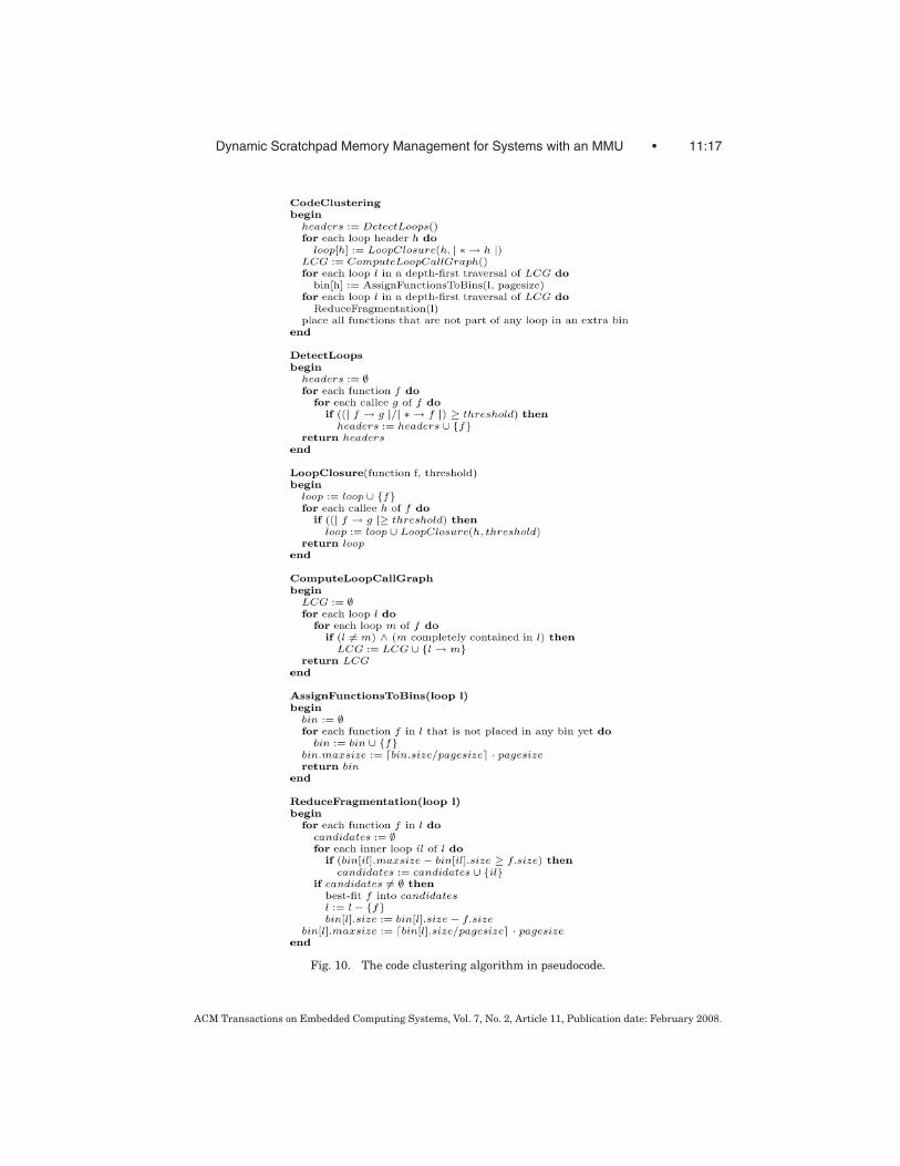
The problem of allocating code blocks to as few pages as possible can bemapped to Knapsack, a well-known, NP-hard problem. If we also consider thetemporal relationship between code blocks, the problem becomes harder thanKnapsack. Therefore, we have developed the following heuristics that workreasonably well for a wide range of benchmarks. Figure 9 illustrates the stepsof the heuristics on a running example. The circles represent functions and thesize of the function is denoted by the number inside the function. The weighton the edges between two functions denotes the number of dynamic calls. Weassume a page size of 128 bytes. Figure 10 contains the most important parts ofthe algorithm in pseudocode form.The algorithm starts with the function calledCodeClustering() at the top of the listing.
In the first step, we detect loops by looking at the dynamic call graph (DCG)(Figure 10, DetectLoops). What we call loop is not a loop in the traditional
ACM Transactions on Embedded Computing Systems, Vol. 7, No. 2, Article 11, Publication date: February 2008.
Dynamic Scratchpad Memory Management for Systems with an MMU • 11:17
Fig. 10. The code clustering algorithm in pseudocode.
ACM Transactions on Embedded Computing Systems, Vol. 7, No. 2, Article 11, Publication date: February 2008.

11:18 • B. Egger et al.
sense. Informally speaking, if a function f that is called k times calls anotherfunction, g , i times with i >> k, then the function f most probably contains aloop. It is possible that f does not contain a traditional loop, but rather callsg at various locations inside f . However, detecting such code patterns as loopsdoes no harm. On the contrary, it allows us to consider loops that other detectiontechniques cannot handle.
The formal definition of a loop is as follows: let | a → b | denote the weightof the edge a → b in the DCG (that is, the number of calls from a to b). | ∗ → b |denotes the sum of the weights of all incoming edges to b, i.e., the total numberof calls to b. We define that a function f is a loop header if there exists a functiong such that
| f → g || ∗ → f | ≥ threshold
(i.e.,the number of calls f → g divided by the number of all incoming calls tof exceeds a certain threshold value). In Figure 9b, the functions c and f havebeen identified as loop headers for a threshold value of 5.
For each loop header hd , the members of the loop are identified by computingthe closure of the loop, closure(hd , hd ). The closure is recursively defined by
closure(hd, f ) =⋃
h ∈ H
closure(hd, h)
with
H :={
h| f → h || ∗ → hd | ≥ 1
}
i.e., the loop consists of all functions h that are called at least as many timesas the header of the loop (Figure 10, LoopClosure). In Figure 9b, closure(c, c) ={c, e, f , g , h} and closure( f , f ) = { f , h}. Note that function g is not a memberof closure( f , f ), because the number of calls to f , | ∗ → f | is larger than thenumber of calls from f to g . Function g is, however, a member of closure(c, c).
After detecting all loops in the DCG, we build the loop call graph (LCG). TheLCG is a directed graph with the loops as nodes and an edge between loop l1
and l2, if loop l2 is an inner loop of l1 (Figure 10, ComputeLoopCallGraph).Figure 9c shows the LCG of the running example with loop f being an innerloop of loop c.
The LCG is then traversed in a depth-first manner (i.e., the innermost loopsare processed first). For each loop li, a bin bli is allocated. We insert all functionsf paged to bin bli that are contained in li and have not yet been allocated to anyother bin (Figure 10, AssignFunctionsToBins). After all nodes in the LCG havebeen processed, the maximum size of each bin is defined by rounding up thesum of all functions in the loop bin to the next multiple of a memory page;
sizemax(bli ) =⌈ ∑
f ∈blisize( f )
pagesize
⌉· pagesize (3)
here, pagesize denotes the size of one memory page. Figures 9d and e show thestate of the LCG and the associated bins after processing f and c, respectively.
ACM Transactions on Embedded Computing Systems, Vol. 7, No. 2, Article 11, Publication date: February 2008.

Dynamic Scratchpad Memory Management for Systems with an MMU • 11:19
Note that even though loop c contains the functions c, e, f , g , and h, only c, e,and g are assigned to bin bc, because f and h have already been placed inbin bf .
Now, we consider all nonleaf nodes of the LCG (i.e., loops containing innerloops). To reduce the internal fragmentation of the loop bins without destroyingthe close temporal relationship between the functions in a loop bin, we pushfunctions allocated to the outer loop bin into the bins of its inner loops usingthe bestfit algorithm [Cormen et al. 1990] as long as the size of the inner loopbin bli does not exceed sizemax(bli) (Figure 10, ReduceFragmentation).
After no more functions can be pushed to inner loops’ bins, the maximum sizeof the outer loop bin is recalculated according to Eq. (3). In Figure 9f, functiong is placed into bf and the maximum size of bin bc is reduced to 128 bytes.
Functions that belong to the paged region, but are not part of any loop, are
placed last. For each unplaced function f pagedk , we follow the DCG up toward the
root. For each caller g encountered on the way up, we compute the loop closure
closure(g , g ) with a threshold of one. If the closure includes both f pagedk and
an existing loop l , we try to place f pagedk in the bin bl of loop l . Any remaining
functions are allocated to an extra bin.If the number of pages in a loop, n, exceeds the number of pages available in
the SPM, NSPM, the thrashing protection heuristics of the SPMM (Section 3.2.1)maps the last k = NSPM−n pages of the loop to the minicache. In order to executeas many instructions from the SPM as possible, we order the functions insidea loop by the number of fetches per word fpw( f ) = fetch f /size f . The functionswith the lowest fpw value are placed last.
5. EVALUATION ENVIRONMENT
We have evaluated the effectiveness of our proposed horizontally partitionedmemory system, and the dynamic SPM management technique on the SNACK-armsim [SNACK 2004] simulator. SNACK-armsim is a cycle-accurate architec-ture simulator that models the ARM9E-S core and supports the ARMv5TEinstruction set. It includes timing models for the pipelined ARM9E-S core, theMMU with the unified TLB, caches with μTLBs, scratchpad memory, the AMBAAHB bus, and external memory.
5.1 Simulation Environment
For this work, we have extended SNACK-armsim in the following ways: (1) theon-chip memory system models the proposed horizontally partitioned memorysystem with an SPM and a minicache as presented in Section 2. (2) TLB en-tries are extended to include the SPM flag (see Figure 3). The flag is computedwhenever the MMU translates a virtual into a physical address. Based on theSPM flag, either the cache or the SPM is accessed. Both μTLBs contain 16entries, and the unified TLB has 64 entries. (3) To accommodate the MMU topage sizes of 1024, 512, 256, 128, and 64 bytes, we extend the address field oftiny page table entries to include bits 9 . . . 6 (Figure 11). Standard tiny PTEsin ARMv5 architecture support only a page size of 1024 bytes. Bits 31 . . . 10contain the physical address, bits 5 and 4 the permission bits, bit 3 and 2
ACM Transactions on Embedded Computing Systems, Vol. 7, No. 2, Article 11, Publication date: February 2008.

11:20 • B. Egger et al.
Fig. 11. Modified tiny PTE format to accommodate page sizes down to 64 bytes.
Table III. Access Latencies in CPU cycles
Memory Hit Miss Memory Read Write
SPM 1 1
Cache 1 2 + writeback + line fetch SDRAM
unified TLB 1 3 + MMU page table walk non-sequential 27 27
μTLB 1 2 + unified TLB access sequential 24 24
determine whether the page is cacheable or bufferable, and the last two bitscontain the tiny page selector (11). For 1024-byte pages, physical addressesare 1-KB aligned, i.e., the bits 9 . . . 0 of the address are always zero. Sixty-four byte pages must be aligned at 64 byte boundaries. Thus, bits 5 . . . 0 ofthe address are zero and do not interfere with the access permission bits, thecacheable/bufferable flags, or the tiny page selector. Note that the PTEs itselfdo not include the SPM flag.
Reducing the page size increases the size of the page table. On ARM archi-tectures, a 1-MB area of memory mapped with tiny (1024 byte) pages consistsof 1024 entries. Each entry is 4 bytes wide. Thus, the size of the (second level)page table is 4 KB. A page size of 512-bytes doubles the size of the page tableto 8 KB. Accordingly, 256-byte pages require 16 KB, 128-byte pages 32 KB, andfor 64-byte pages, the second-level page table consumes as much as 64 KB perpage table.
For the simulations, the processor core clock in SNACK-armsim is set to200 MHz. The data cache and the instruction cache of the reference case arevirtually indexed and physically tagged. The latencies of the cache, the SPM,the unified and the μTLBs, and the external memory (SDRAM) are shown inTable III. Cache, unified TLB, and both μTLBs have a hit access latency ofone. The latencies vary in case of a miss: the μTLBs have a miss latency of2 plus that of the following unified TLB access. That is, three cycles in totalif the unified TLB hits. If the unified TLB misses, the virtual address is sentto the MMU, which then performs a page table walk and computes the SPMflag. The page table walk consists of one or two nonsequential memory accesses.If a cache misses, it incurs a miss latency of two cycles plus the latency of aneventual writeback (in case the line is dirty) plus the following burst access tothe external memory to fill the cache line.
5.2 Performance Metrics
We use the total execution time as the performance metric and the total energyconsumed by the core and the memory subsystem as the energy metric. Theexecution time is computed by dividing the measured number of core clocks by
ACM Transactions on Embedded Computing Systems, Vol. 7, No. 2, Article 11, Publication date: February 2008.

Dynamic Scratchpad Memory Management for Systems with an MMU • 11:21
Table IV. Per-Word Access Energy and Power Parameters
4-way Assoc. Cache Direct-Mapped Cache
Size Linesize Energy Size Linesize Energy
[KB] Assoc [words] [nJ] [KB] Assoc [words] [nJ]
1 4-way 8 0.538 1 1-way 8 0.197
2 4-way 8 0.542 2 1-way 8 0.203
4 4-way 8 0.550 4 1-way 8 0.215
8 4-way 8 0.564 8 1-way 8 0.237
Minicache TLB
Size Linesize Energy Energy
[B] Assoc [words] [nJ] Type Assoc Entries [nJ]
unified TLB 2-way 64 0.141
512 1-way 4 0.196 μTLB full 16 0.125
(a)
SPM SDRAM
Size Energy Energy
[KB] [nJ] Dynamic [nJ]
3 0.139 read random 11.747
4 0.145 read burst 3.373
6 0.160 write random 10.397
10 0.183 write burst 1.659
Core SDRAM
Power Power
Model [mW/MHz] Static [mW]
ARM926EJ-S 0.360 standby 9.600
(b)
the core clock frequency
Ttotal = # core clocks
core frequency
The consumed energy is computed by summing up the the core energy, the on-chip memory system with both μTLBs, the unified TLB, the instruction and thedata cache, the SPM, the off-chip bus, and the external memory (SDRAM)
Etotal = Ecore
+ Eunified TLB + Ei−μTLB + Ed−μTLB
+ Eicache + Edcache + ESPM
+ Eext static + Eext dynamic
The core energy is computed by
Ecore = Ttotal · Pcore · fcore
where fcore is the core frequency in MHz and pcore the power per MHz parameterfrom Table IVa. The energies consumed by the TLBs, the caches and the SPM,respectively, are computed by
ETLB = eTLB(hit + miss)
Ecache = ecache(hit + miss · linesize)
ESPM = eSPM(read + write)
ACM Transactions on Embedded Computing Systems, Vol. 7, No. 2, Article 11, Publication date: February 2008.

11:22 • B. Egger et al.
where eTLB, ecache, and eSPM are taken from Tables IVa and b. Hit and missdenote the number of hits and the number of misses for the correspondingmemory structures, respectively. The μTLBs and the unified TLB are modeledas caches with a 4-byte linesize, hence writing a datum costs one word write.The cache energy is computed accordingly, only this time with the correspondinglinesize. The SPM energy is simply the access energy multiplied by the sum ofreads and writes.
The SDRAM energy is composed of static and dynamic energy [MicronTechnology, Inc. 2004]. We have modeled the low-power 64-MB SamsungK4X51163PC SDRAM [Samsung Semiconductor 2005] with a memory bus fre-quency fmem = 66 MHz and a supply voltage Vdd = 1.8 V. The static energyconsumption, Eext static, includes the standby power and the power to periodi-cally refresh the SDRAM cells and is computed by
Eext static = Ttotal · Pstandby
where Pstandby is the static power consumption of the SDRAM (Table IVa). Thedynamic energy,
Eext dynamic = ereadrandom · readrandom + ereadburst · readburst
+ ewriterandom · writerandom + ewriteburst · writeburst
includes both SDRAM dynamic energy and the memory bus energy. The en-ergies eread/writerandom/burst denote the per-word access energy for a random/burstread/write access, respectively.
Table IV lists the values used for the energy calculations. All energy param-eters are the energy required per word (4-byte) access, including the values forSDRAM read/write burst. The cache, SPM, minicache, and TLB access ener-gies were computed for 0.13 μm technology using CACTI [Wilton and Jouppi1996]. The core power consumption for a 0.13 μm ARM926EJ-S core withoutcaches was taken from [ARM926EJ-S 2002]. The static and dynamic energy ofthe SDRAM were computed using the System Power Calculator from [MicronTechnology, Inc 2003], bus energy was taken from [Shrivastava et al. 2005].
5.3 Benchmarks
We use 15 embedded applications to evaluate our work. These include ninebenchmarks from MiBench [Guthaus et al. 1998] and MediaBench [Lee et al.1997], a H.264 video decoder [H.264 2003], the official ISO MP3 decoder [MP31996], MPEG-4 XviD encoding/decoding [Xvid 2005], and a public key encryp-tion/decryption tool, Pretty Good Privacy (PGP) [PGPi 2002]. We chained thebenchmarks Quicksort, Dijkstra, SHA, ADPCM-enc, ADPCM-dec, and Bitcounttogether into one benchmark called Combine. Each of the smaller benchmarksis executed once in Combine to represent an embedded application with mul-tiple phases. Table V summarizes the characteristics of each benchmark. Weset M = 2, mcache = 0.02, and threshold = 4 for the clustering algorithm(Section 4.3) for all benchmarks.
We compare the horizontally partitioned memory system with our dynamicSPM management technique to a fully-cached system. For the fully-cached
ACM Transactions on Embedded Computing Systems, Vol. 7, No. 2, Article 11, Publication date: February 2008.
Dynamic Scratchpad Memory Management for Systems with an MMU • 11:23
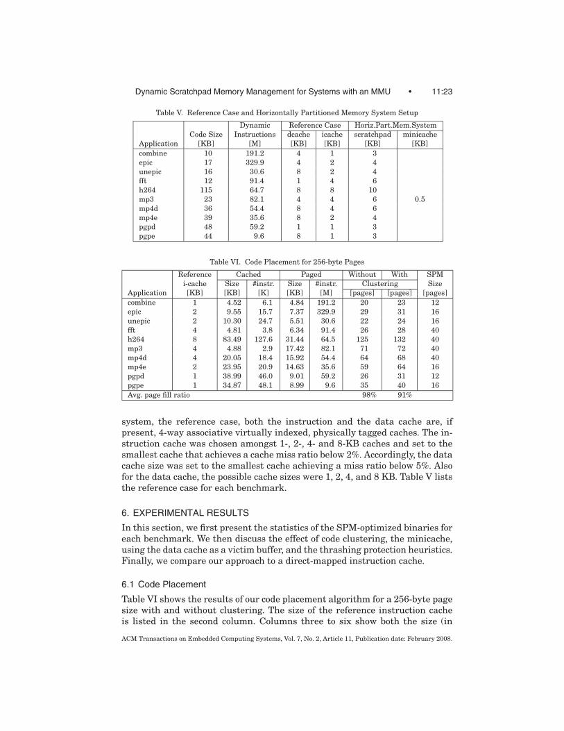
Table V. Reference Case and Horizontally Partitioned Memory System Setup
Dynamic Reference Case Horiz.Part.Mem.System
Code Size Instructions dcache icache scratchpad minicache
Application [KB] [M] [KB] [KB] [KB] [KB]
combine 10 191.2 4 1 3
epic 17 329.9 4 2 4
unepic 16 30.6 8 2 4
fft 12 91.4 1 4 6
h264 115 64.7 8 8 10
mp3 23 82.1 4 4 6 0.5
mp4d 36 54.4 8 4 6
mp4e 39 35.6 8 2 4
pgpd 48 59.2 1 1 3
pgpe 44 9.6 8 1 3
Table VI. Code Placement for 256-byte Pages
Reference Cached Paged Without With SPM
i-cache Size #instr. Size #instr. Clustering Size
Application [KB] [KB] [K] [KB] [M] [pages] [pages] [pages]
combine 1 4.52 6.1 4.84 191.2 20 23 12
epic 2 9.55 15.7 7.37 329.9 29 31 16
unepic 2 10.30 24.7 5.51 30.6 22 24 16
fft 4 4.81 3.8 6.34 91.4 26 28 40
h264 8 83.49 127.6 31.44 64.5 125 132 40
mp3 4 4.88 2.9 17.42 82.1 71 72 40
mp4d 4 20.05 18.4 15.92 54.4 64 68 40
mp4e 2 23.95 20.9 14.63 35.6 59 64 16
pgpd 1 38.99 46.0 9.01 59.2 26 31 12
pgpe 1 34.87 48.1 8.99 9.6 35 40 16
Avg. page fill ratio 98% 91%
system, the reference case, both the instruction and the data cache are, ifpresent, 4-way associative virtually indexed, physically tagged caches. The in-struction cache was chosen amongst 1-, 2-, 4- and 8-KB caches and set to thesmallest cache that achieves a cache miss ratio below 2%. Accordingly, the datacache size was set to the smallest cache achieving a miss ratio below 5%. Alsofor the data cache, the possible cache sizes were 1, 2, 4, and 8 KB. Table V liststhe reference case for each benchmark.
6. EXPERIMENTAL RESULTS
In this section, we first present the statistics of the SPM-optimized binaries foreach benchmark. We then discuss the effect of code clustering, the minicache,using the data cache as a victim buffer, and the thrashing protection heuristics.Finally, we compare our approach to a direct-mapped instruction cache.
6.1 Code Placement
Table VI shows the results of our code placement algorithm for a 256-byte pagesize with and without clustering. The size of the reference instruction cacheis listed in the second column. Columns three to six show both the size (in
ACM Transactions on Embedded Computing Systems, Vol. 7, No. 2, Article 11, Publication date: February 2008.

11:24 • B. Egger et al.
Kilobytes) and the number of dynamic instructions for the cached and pagedcode regions. For the cached code region, the number of dynamic instruction isshown in thousands and for the paged region in millions.
On average, more than 99.9% of all dynamic instruction fetches are placedin the paged code region and only a few thousand fetches are covered by theminicache. Note that the actual number of fetches from the minicache will behigher for two reasons: first, the SPM manager itself is located in the cachedregion. The more pagefaults occur, the more often the SPMM is invoked andgenerates cache accesses. Second, the thrashing-protection heuristics in theSPMM (see Section 3.2.1) will map the last few pages of loops that are largerthan the entire SPM to cached code regions.
Without clustering, the postpass optimizer generates less pages in the page-able area than with clustering (Table VI, columns seven and eight). The pageswithout clustering (98% fill ratio) are less fragmented than the pages afterclustering (91%). The reason is that without clustering, the postpass optimizerallocates all pageable code into one single, big bin. When dividing the bin intopages, only the very last page can possibly be fragmented. With clustering,however, the postpass optimizer assigns a bin to each loop. Since each loop binis divided into pages, we have more fragmentation.
6.2 The Effect of Clustering
Figure 12a compares the normalized energy consumption of the reference im-age to SPM-optimized images when code clustering is disabled. The total energyconsumption is split up into CPU core, SDRAM (includes static and dynamicenergy), TLB, instruction cache, and SPM energy. The CPU core-energy con-sumption is directly proportional to the execution time, i.e., the execution timeis represented by the fraction of the CPU Core bar. Figure 12b shows the nor-malized number of external memory accesses. The total number is split up intoinstruction fetch, data read, and data write accesses. Figure 12c displays thenumber of page faults for the different MMU page sizes on a logarithmic scale.
The reference case, denoted ref, is the original (SPM-unaware) binary imagerun on a standard ARM926EJ-S core with an instruction, but no data cache.For each application, the reference instruction cache, SPM, and minicache sizesare set to the corresponding values in Table V. The SPM-optimized imagesare generated by our postpass optimizer with code clustering disabled (seeSection 4.3). Figure 12 shows the results of each application for an MMU pagesize of 64, 128, 256, 512 and 1024 bytes (denoted 64b, 128b, 256b, 512b, and1024b, respectively).
The number of page faults is directly related to the size of the working set. Ifthe number of pages in the working set exceeds the number of pages availablein the SPM, the application will thrash. Intuitively, we expect better results forsmaller MMU pages. Without clustering, temporally local code is potentiallyscattered all over the pageable code region, that is, with larger page sizes,chances increase that the loaded page contains only a small part of actuallyexecuted code, and the rest of the page consists of code that is not executed.However, smaller pages also cause more page faults and, at a certain page size,
ACM Transactions on Embedded Computing Systems, Vol. 7, No. 2, Article 11, Publication date: February 2008.

Dynamic Scratchpad Memory Management for Systems with an MMU • 11:25
Fig. 12. Memory system: no data cache and no minicache. Code clustering disabled.
ACM Transactions on Embedded Computing Systems, Vol. 7, No. 2, Article 11, Publication date: February 2008.

11:26 • B. Egger et al.
the advantage of a smaller pages is canceled out by the increasing overheadof the SPMM. Furthermore, the performance of the μTLBs with its 16 entriesalso decreases with smaller page sizes, because the working set consists of morepages than for bigger page sizes.
We observe the expected behavior for fft, h264, mp3, pgpd, and pgpe. Com-bine, fft, pgpd, and pgpe start thrashing at 1024 byte pages, which results in asignificantly higher execution time, energy consumption, and also more exter-nal memory accesses. H264, mp3, mp4d, and mp4e suffer from a high numberof page faults (Figure 12c) and consume significantly more energy than thereference case for all page sizes.
From Figure 12b and c we observe that, even without clustering or a mini-cache, the number of external memory accesses decreases as long as the num-ber of page faults is reasonably small. Without a minicache, a high number ofpage faults will inevitably lead to poor performance and lots of external mem-ory accesses because the SPM manager is located in the external memory. Weplace the SPMM in external memory and not in the SPM because of the follow-ing considerations: it only makes sense to place the SPMM in the SPM whenit is accessed very frequently and this is only the case when an applicationthrashes. The SPM pages occupied by the SPMM, however, are not availableto the application any more, which will increase the thrashing. Furthermore,some applications might only thrash if the SPMM is placed in the SPM.
Figures 13a–c display the results for the same hardware configuration withcode clustering enabled. Figure 13c shows the relative number of page faultswith clustering compared to no clustering. For the applications that suffer froma high number of page faults without clustering (h264, mp3, mp4d, and mp4e),we observe that clustering effectively reduces the size of the working set. Re-ducing the number of page faults has a direct impact on execution time, energyconsumption, and the external memory accesses, as can be seen by comparing,for example, mp3 in Figure 12a and b with Figure 13 a and b.
Clustering can also cause thrashing as can be observed in Figure 13c for epicwith 1024, or fft with 512- and 1024-byte pages. This is because of the increasedfragmentation whose effect grows with larger page sizes.
6.2.1 TLB Performance. Figure 14 shows the performance of the 16-entry,fully associative instruction μTLB and the 64-entry, two-way unified TLB ona logarithmic scale in dependence on the page size. The instruction μTLB isaccessed for each instruction fetched by the core. The number of instructionμTLB hits is labeled Inst μTLB Hit. μTLB, misses are handled by the unifiedTLB, which either hits or misses, i.e., the number of μTLB misses is the sumof Unified TLB Miss and Unified TLB Hit.
Not surprisingly, the performance of the μTLB suffers with smaller MMUpage sizes. One factor is that the number of virtual-to-physical address trans-lations doubles whenever we divide the page size by two. For example, thevirtual-to-physical address translations of a working set of 4-KB code can becached by the TLB with four entries for an MMU page size of 1024 bytes. For512-byte pages we need 8 entries, for 256-byte pages 16, for 128-byte pages 32,and for 64-byte pages 64 entries to cache the address translations of 4 KB of
ACM Transactions on Embedded Computing Systems, Vol. 7, No. 2, Article 11, Publication date: February 2008.

Dynamic Scratchpad Memory Management for Systems with an MMU • 11:27
Fig. 13. Memory system: no data cache and no minicache. Code clustering enabled.
ACM Transactions on Embedded Computing Systems, Vol. 7, No. 2, Article 11, Publication date: February 2008.

11:28 • B. Egger et al.
Fig. 14. TLB Performance for varying page sizes.
code. A second reason is that the SPMM invalidates the affected entry in theTLB whenever it replaces a page in the SPM, namely the entry of the evictedpage.
6.3 The Minicache
With only a few thousand instruction fetches from external memory, one couldassume that the addition of a minicache is not necessary. This is, however, notso, as we show in this section.
The purpose of the minicache is twofold: First, it caches the SPM managerthat is always placed in the cacheable code region. For applications with fewpage faults, executing the SPMM from the minicache (and not the SPM) in-curs only a negligible performance penalty. Applications with a high numberof page faults benefit more from executing the SPMM in the SPM. However,the SPM area occupied by the SPMM itself (about 250 bytes) is not availablefor the application, which only further increases the number of page faults.Second, one of the goals of the proposed memory system is that it also runsSPM-unaware binaries with acceptable performance. Without any instructioncaching at all, SPM-unaware applications are executed directly from externalmemory with an unacceptable increase in execution time and energy consump-tion (Section 6.3.1).
Figure 15 shows the results for a setup with a 512-byte, direct-mapped in-struction minicache, SPM, and no data cache. Compared to the identical setupwithout a minicache (Figure 13), the energy consumption and the number ofexternal memory accesses drop below the reference case for at least one pagesize for all benchmarks except h264. For h264, even with the minicache, andfor all page sizes, the reference image consumes less energy and generatesless external memory accesses as the SPM-optimized binary. This is becauseh264 contains one big loop with a code size of 13.5 KB. The loop is biggerthan the available SPM (10 KB), so the SPMM’s thrashing-protection heuristic(Section 3.2.1) will map the last 3.5 KB of code as cacheable pages. However,because the loop calls several inner loops, the working set still exceeds thenumber of available SPM pages and h264 thrashes.
ACM Transactions on Embedded Computing Systems, Vol. 7, No. 2, Article 11, Publication date: February 2008.

Dynamic Scratchpad Memory Management for Systems with an MMU • 11:29
Fig. 15. Memory system: no data cache and with minicache. Code clustering enabled.
ACM Transactions on Embedded Computing Systems, Vol. 7, No. 2, Article 11, Publication date: February 2008.

11:30 • B. Egger et al.
Fig. 16. The effect of the minicache on SPM-unaware binaries.
Table VII. Average Latency for Handling a Pagefault
Page size 1024 bytes 512 bytes 256 bytes 128 bytes 64 bytes
Avg. number of core clocks 1263 809 673 647 560
Avg. number of instructions 157 104 82 71 64
6.3.1 SPM-Unaware binaries. As mentioned above, one of the design goalsof the proposed memory architecture was that SPM-unaware applications runwith acceptable performance and energy consumption. In contrast to previouswork with only SPM, unoptimized applications can still profit from the mini-cache. Figure 16 shows the effect of the minicache on the execution time andenergy consumption of unoptimized binaries. Without a minicache, the unopti-mized applications run more than 13-fold slower and consume almost 10 timesmore energy than the reference runs. With the minicache, however, we onlysuffer a 2.9-fold increase in runtime with 3.2 times more energy consumed.
6.4 Using the Data Cache as a Victim Buffer
The proposed horizontally partitioned memory architecture is completed byadding a data cache. The SPMM uses the data cache as a victim cache forpageable code. Whenever the SPMM copies a code page from external memoryto the SPM, the page is loaded through the data cache. Unlike a traditionalvictim cache, pages evicted from the SPM are not written back to the datacache. To study the effect of data cache pollution caused by caching the pageableregion, the data cache size is set to the smallest cache size that achieves a missratio below 5% (Table V).
The reference images run on an ARM926EJ-S core with an instruction anda data cache. For each application, the instruction and data cache sizes areset to the corresponding values in Table V. For the SPM-optimized images, theinstruction cache has been replaced by an SPM and a 512-byte minicache andthe data cache is identical to that of the reference case.
Table VII lists the average latency for handling a page fault in terms ofcore clocks and executed instructions. The SPM management code consistingof the low-level interrupt handler, the page replacement, and the page table
ACM Transactions on Embedded Computing Systems, Vol. 7, No. 2, Article 11, Publication date: February 2008.

Dynamic Scratchpad Memory Management for Systems with an MMU • 11:31
TLB management requires 55 instructions, independent of the page size. Theblock copy routine executes more instructions as the page size increases.
Figure 17 shows the final results for our horizontally partitioned memorysystem in conjunction with the SPMM. With the addition of the data cache, allbut one benchmark consume less energy than the reference case for at leastone page size setting. Exploiting the data cache as a victim buffer increases thecache miss rate slightly, especially for benchmarks with a relatively small datacache that suffer from a high number of page faults (h264, mp4d, and mp4e)(Figure 17c). However, even though the code blocks pollute the data cache upto a certain degree, our experiments show that the performance gain by faroutweighs the additional cost caused by an increased number of data cacheaccesses. Note that again the number of page faults is not reduced by addinga data cache, but the number of external memory accesses can be significantlyreduced.
Table VIII lists the average reduction in execution time and energy consump-tion for each application, depending on the MMU’s page size. Overall, with apage size of 256 bytes, on average, we achieve a 31% improvement in perfor-mance and a 35% reduction in energy consumption compared to a fully-cachedcore. Furthermore, our horizontally partitioned memory system requires 8%less die area than the corresponding memory system with an instruction and adata cache.
6.5 Effectiveness of the Thrashing-Protection Heuristics
Table IX shows the effectiveness of the thrashing-protection heuristics. InFigure 18, for each benchmark, the normalized execution time, energy, andnumber of page faults are shown for the reference case and the SPM-optimizedbinary with disabled, and enabled thrashing-protection heuristics, respectively.For combine, epic, unepic, pgpd, and pgpe, the working set fits into the numberof available SPM pages, therefore turning the thrashing-protection on has nobig effect. For fft, h264, and mp3, the thrashing-protection heuristics signifi-cantly reduce the number of page faults. The heuristics do not work well formp4d and mp4e. This is because the current implementation considers eachloop’s working set size independent of whether this loop has inner loops or not.Even so, the thrashing-protection heuristics affects neither the performancenor the energy consumption negatively for all benchmarks.
6.6 Comparison Against a Direct-Mapped Instruction Cache
Set-associative caches require significantly more die area and energy per ac-cess than direct-mapped ones, the former because of the more complex con-trol logic and the latter because of the parallel look-ups. Because of the bet-ter performance, however, many embedded processors contain set-associativecaches [ARM926EJ-S 2002; ARMv6 2002; Intel XScale 2002]. In this section,we compare the reference case with its 4-way set-associative cache against adirect-mapped cache that requires a comparable die area and the horizontallypartitioned memory architecture. On the 4-way set-associative cache and thedirect-mapped cache, we run the original binary. On the horizontally partitionedmemory architecture, we run the SPM-optimized binary with a page size of 256
ACM Transactions on Embedded Computing Systems, Vol. 7, No. 2, Article 11, Publication date: February 2008.

11:32 • B. Egger et al.
Fig. 17. Memory system: with data cache and minicache. Code clustering enabled.
ACM Transactions on Embedded Computing Systems, Vol. 7, No. 2, Article 11, Publication date: February 2008.

Dynamic Scratchpad Memory Management for Systems with an MMU • 11:33
Table VIII. Memory System: With Data Cache, Minicache, and Code Clustering Enabled
Pagesize 64b 128b 256b 512b 1024b
Time Energy Time Energy Time Energy Time Energy Time Energy
Benchmark (%) (%) (%) (%) (%) (%) (%) (%) (%) (%)
combine 96 77 93 74 93 74 93 74 93 74
epic 111 86 85 63 84 62 84 62 240 308
unepic 167 135 100 74 99 74 99 74 99 74
fft 86 90 52 53 41 39 74 107 87 146
h264 121 135 112 120 95 104 110 138 104 155
mp3 94 101 82 85 42 50 38 45 50 79
mp4d 106 119 75 84 65 72 56 63 54 61
mp4e 111 119 82 85 79 81 74 76 76 77
pgpd 86 65 84 62 83 61 83 62 84 63
pgpe 59 65 48 52 47 51 48 52 49 53
Geom. mean 101 96 79 73 69 65 72 71 84 93
Table IX. Number of Page Faults Without and With Thrashing Protection
Thrashing Protection Thrashing Protection
Benchmark Off On Benchmark Off On
combine 21 18 mp3 157946 19449
epic 689 689 mp4d 49453 47720
unepic 27 26 mp4e 19185 19185
fft 60211 27 pgpd 126 125
h264 191921 66805 pgpe 211 211
bytes. Table X lists the corresponding direct-mapped cache for various sizes of a4-way set-associative cache. A 1-KB 4-way set-associative cache with a die areaof 0.369 mm2 and an access energy of 0.538 nJ/word, for example, is replaced bya 4-KB direct-mapped cache with a die area of 0.331 mm2 and an access energyof 0.215 nJ/word.
Figure 19 shows the normalized execution time and energy consumptionfor the reference case, a direct-mapped cache with comparable die area, andthe horizontally partitioned memory architecture. Thanks to its larger size,the direct-mapped cache outperforms the 4-way set-associative cache for mostbenchmarks. Compared to the horizontally partitioned memory system, itachieves a slightly better reduction in energy consumption only for benchmarksthat suffer from a high number of page faults (h264, mp4d, mp4e). Comparedto the direct-mapped cache, the horizontally partitioned memory architectureachieves, on average, a 16% improvement in runtime performance and a 14%reduction in energy consumption.
7. RELATED WORK
Existing work on SPM allocation can be divided roughly into two classes: stat-ically allocated and dynamically managed scratchpad memories. In staticallyallocated SPM allocation, the scratchpad memory is initialized with the desig-nated program parts at load time and its contents do not change during run-time. Dynamically managed SPM, on the other hand, is characterized by thefact that the contents of the SPM change while the program executes. The pro-gram points where code and/or data are moved back and forth from the SPM
ACM Transactions on Embedded Computing Systems, Vol. 7, No. 2, Article 11, Publication date: February 2008.

11:34 • B. Egger et al.
Fig. 18. The effectiveness of the thrashing-protection heuristics.
Table X. 4-Way Associative and Corresponding Direct-Mapped
Cache
4-Way Assoc. Cache Corresp. Direct-Mapped Cache
Size Die Area Energy Size Die Area Energy
[KB] [mm2] [nJ/word] [KB] [mm2] [nJ/word]
1 0.369 0.538 4 0.331 0.215
2 0.415 0.542 4 0.331 0.215
4 0.528 0.550 8 0.616 0.237
8 0.733 0.564 8 0.616 0.237
to the main memory are usually predetermined locations immediately before asubstantial change in program behavior (e.g., before loops). Both statically allo-cated and dynamically managed SPM can be further classified into techniquesthat consider only instructions (code), only data, or both.
Static SPM allocation techniques are presented in [Angiolini et al. 2003,2004; Banakar et al. 2002; Poletti et al. 2004; Nguyen et al. 2005; Verma et al.2004, 2005]. Except for [Nguyen et al. 2005], all of these approaches requireknowledge of the SPM size at compile time. In [Angiolini et al. 2003, 2004], theauthors present SPM allocation schemes that select code blocks which promisethe highest energy savings using an algorithm based on dynamic programming.While [Angiolini et al. 2003] requires special hardware support to split the SPMinto several partitions, [Angiolini et al. 2004] uses a postpass optimizer to mod-ify the necessary instructions so that the application runs on a unified SPM.Banakar et al. [2002] solves the static assignment with a knapsack algorithm,both for code and data blocks. In [Verma et al. 2004], memory objects are selectedbased on a cache conflict graph obtained through cache hit/miss statistics. Theoptimal set of memory objects is selected using an integer linear program (ILP)variant of the knapsack algorithm. In [Nguyen et al. 2005], the decision of whichblocks should go to the SPM is delayed until the application is loaded, makingit independent from the actual scratchpad memory size. Obviously, some profil-ing information has to be embedded into the application binary, but the authorsreport only a minimal image size increase. Poletti et al. [2004] and Verma et al.[2005] both aim at multitasking systems. While Poletti et al. [2004] propose
ACM Transactions on Embedded Computing Systems, Vol. 7, No. 2, Article 11, Publication date: February 2008.

Dynamic Scratchpad Memory Management for Systems with an MMU • 11:35
Fig. 19. Comparison against a direct-mapped cache.
an API that helps the programmer move blocks back and forth between theSPM and the main memory, [Verma et al. 2005] is an automatic approach. Theauthors present three sharing strategies: nonsaving, saving, and hybrid. In thenonsaving approach, the scratchpad memory is completely allocated to the cur-rently active task. The saving approach divides the scratchpad evenly betweenthe applications. The hybrid approach is a mixture of the saving and nonsavingmethod. Since [Verma et al. 2005] presents a static allocation method, both theSPM size as well as the sharing strategy must be decided at compile time.
Dynamically allocated SPM algorithms are presented in [Egger et al. 2006a,2006b; Janapsatya et al. 2006; Kandemir and Choudhary 2002; Kandemir et al.2001; Li et al. 2005; Park et al. 2004; Steinke et al. 2002; Udayakumaran andBarua 2003]. Both [Kandemir and Choudhary 2002] and [Kandemir et al. 2001]focus on data arrays accessed from well-structured loop kernels. Arrays aresplit into so-called tiles to allow only parts of an array to be copied to the SPM,which allows arrays bigger than the SPM size to be allocated to the SPM. Alsoin [Li et al. 2005], the authors focus on assigning data arrays to the SPM. Todetermine the most beneficial set, they first assign registers to so-called registerclasses based on their size. Each register class gets a fixed share of the SPM.Using a conflict graph of live ranges, a graph-coloring algorithm determineswhich array is to be allocated to the SPM at what program points. In [Steinkeet al. 2002], code blocks are dynamically copied to the SPM directly before loops.The optimal set is determined using an ILP. [Udayakumaran and Barua 2003]focuses on performance optimization and considers local and global data. Theprogram’s control-flow graph (CFG) is annotated with timestamps to form adata program relationship graph (DPRG). Using greedy heuristics, the mostpromising candidates are copied to and from the SPM at well-defined copypoints. In [Egger et al. 2006a], loop nests are copied on demand to the SPM.The most beneficial set of loops for a given SPM size is determined by solving anILP. A dynamic SPM allocation for code is presented in [Janapsatya et al. 2006].The allocation is based on the so-called concomitance metric, which indicateshow correlated in time the execution of various blocks of code are. [Park et al.2004] focuses on demand paging techniques to copy code from Flash memory to
ACM Transactions on Embedded Computing Systems, Vol. 7, No. 2, Article 11, Publication date: February 2008.

11:36 • B. Egger et al.
SRAM before execution. [Egger et al. 2006b] introduces the use of SPM mappedinto the virtual address space. It copies frequently executed code to the SPM on-demand and introduces the horizontally partitioned memory subsystem thatthis work builds on. In [Cho et al. 2007], the authors apply the same techniqueto the data side: data blocks are transparently mapped to the data SPM or theexternal memory using the MMU’s address translation mechanism.
Finally, in [Dominguez et al. 2005], the authors propose an SPM allocationscheme for heap data. Promising candidates are assigned a fixed-size bin thatcan hold n elements of a dynamically allocated variable. At runtime, only thefirst n objects are allocated to the SPM. While the bins are fixed in size, theirmemory location may change during program execution, making this allocationtechnique a dynamic one.
The horizontal partitioning of memory architectures has been examined re-cently in [Shrivastava et al. 2005]. Inspired by the memory architecture of theIntel XScale architecture with a large main data cache and a 2 KB minicache,the authors show that, by cleverly allocating the data objects to one of thecaches, a substantial amount of energy can be saved.
In [Machanick et al. 1998], the unified second-level cache is replaced bySRAM that is managed by software, and the main memory serves as a pagingdevice for the SRAM. Pages are copied in (and out) of the SRAM whenever one ofthe first-level caches misses. In principle, it is possible to apply the same conceptto the first-level caches, however, since the latency of the first-level cache ismuch more critical than that of the second-level one, unmodified software willprobably not run at a satisfactory performance anymore. Applying the code-clustering techniques described in our work would be one possibility.
8. CONCLUSION AND FUTURE WORK
This paper presents a dynamic SPM allocation technique for contemporaryportable systems with an MMU. An SPM manager loads frequently executedcode into the SPM on demand. The SPMM tracks page accesses by intercept-ing the MMU’s page fault exception mechanism. SPM-optimized binaries aregenerated by a postpass optimizer. Based on profiling information, the postpassoptimizer extracts the frequently executed code and places it into the pageablecode region. By analyzing the dynamic call graph, the postpass optimizer de-tects loops and groups their code together to minimize the size of the workingset. To efficiently run the SPM-optimized images, we propose a horizontallypartitioned memory system where the instruction cache is replaced by a di-rect mapped, physically addressed minicache and a scratchpad memory. Theaddress translation is serialized with the actual memory access, which enablesthe memory system to access either only the SPM or the minicache. The SPM-optimized images are binary portable across varying hardware configurations,and even run unmodified on cores with no SPM at all. Thanks to the minicache,the proposed memory architecture even executes SPM-unaware applicationswith acceptable performance.
We have evaluated the proposed dynamic SPM allocation technique on thehorizontally partitioned memory subsystem using fifteen embedded applica-tions, including an H.264 video decoder, an MP3 decoder, a MPEG-4 video
ACM Transactions on Embedded Computing Systems, Vol. 7, No. 2, Article 11, Publication date: February 2008.

Dynamic Scratchpad Memory Management for Systems with an MMU • 11:37
encoder/decoder, and a public-key encryption/decryption tool. We find that withan MMU page size of 256 bytes, on average, we achieve a 8% reduction in diearea consumption, a 31% improvement in runtime, and a 35% reduction inenergy consumption.
In our future work, we extend the dynamic SPM allocation technique tomultitasking environments. Another direction for future research can be toreplace the data cache with a horizontally partitioned memory subsystem.
REFERENCES
ANGIOLINI, F., BENINI, L., AND CAPRARA, A. 2003. Polynomial-time algorithm for on-chip scratch-
pad memory partitioning. In CASES ’03: Proceedings of the 2003 International Conference onCompilers, Architecture and Synthesis for Embedded Systems. 318–326.
ANGIOLINI, F., MENICHELLI, F., FERRERO, A., BENINI, L., AND OLIVIERI, M. 2004. A post-compiler ap-
proach to scratchpad mapping of code. In CASES ’04: Proceedings of the 2004 InternationalConference on Compilers, Architecture, and Synthesis for Embedded Systems. 259–267.
ARM926EJ-S 2002. ARM926EJ-S Jazelle-enhanced macrocell,. http://www.arm.com/products/
CPUs/ARM926EJ-S.html.
ARMv6 2002. ARM Architecture Version 6 (ARMv6),. http://www.arm.com.
BANAKAR, R., STEINKE, S., LEE, B.-S., M.BALAKRISHNAN, AND MARWEDEL, P. 2002. Scratchpad mem-
ory: A design alternative for cache on-chip memory in embedded systems. In Proc. of the 10thInternational Symposium on Hardware/Software Codesign (CODES).
CHO, H., EGGER, B., LEE, J., AND SHIN, H. 2007. Dynamic data scratchpad memory manage-
ment for a memory subsystem with an mmu. In LCTES ’07: Proceedings of the 2007 ACMSIGPLAN/SIGBED Conference on Languages, Compilers, and Tools. ACM Press, New York.
195–206.
CORMEN, T. H., LEISERSON, C. E., AND RIVEST, R. L. 1990. Introduction to Algorithms. The MIT
Press, Cambridge, MA.
DENNING, P. J. 1967. The working set model for program behavior. In SOSP ’67: Proceedingsof the 1st ACM Symposium on Operating System Principles. ACM Press, New York. 15.1–
15.12.
DOMINGUEZ, A., UDAYAKUMARAN, S., AND BARUA, R. 2005. Heap data allocation to scratch-pad mem-
ory in embedded systems. Journal of Embedded Computing 1, 4.
EGGER, B., KIM, C., JANG, C., NAM, Y., LEE, J., AND MIN, S. L. 2006a. A dynamic code place-
ment technique for scratchpad memory using postpass optimization. In CASES ’06: Proceedingsof the 2006 International Conference on Compilers, Architecture and Synthesis for EmbeddedSystems.
EGGER, B., LEE, J., AND SHIN, H. 2006b. Scratchpad memory management for portable systems
with a memory management unit. In EMSOFT’06: Proceedings of the 6th ACM & IEEE Interna-tionel Conference on Embedded Software.
FOTHERINGHAM, J. 1961. Dynamic storage allocation in the atlas computer, including an automatic
use of a backing store. Commun. ACM 4, 10, 435–436.
GUTHAUS, M. R., RINGENBERG, J. S., ERNST, D., AUSTIN, T. M., MUDGE, T., AND BROWN, R. B. 1998.
Mibench: A free, commercially representative embedded benchmark suite. In Proceedings of the4th Annual Workshop on Workload Characterization.
H.264 2003. H.264 Video Codec. http://www.itu.int/rec/T-REC-H.264.
Intel IXP Network Processor 2002. The Intel IXP Network Processor,. http://developer.intel.
com/technology/itj/2002/volume06issue03/.
Intel XScale 2002. Intel XScale Architecture. http://www.intel.com.
JANAPSATYA, A., IGNJATOVIC;, A., AND PARAMESWARAN, S. 2006. A novel instruction scratchpad mem-
ory optimization method based on concomitance metric. In ASP-DAC ’06: Proceedings of the 2006Conference on Asia South Pacific Design Automation. 612–617.
KANDEMIR, M. AND CHOUDHARY, A. 2002. Compiler-directed scratch pad memory hierarchy design
and management. In DAC ’02: Proceedings of the 39th Conference on Design Automation. 628–
633.
ACM Transactions on Embedded Computing Systems, Vol. 7, No. 2, Article 11, Publication date: February 2008.

11:38 • B. Egger et al.
KANDEMIR, M., RAMANUJAM, J., IRWIN, J., VIJAYKRISHNAN, N., KADAYIF, I., AND PARIKH, A. 2001. Dy-
namic management of scratch-pad memory space. In DAC ’01: Proceedings of the 38th Conferenceon Design Automation. 690–695.
LEE, C., POTKONJAK, M., AND MANGIONE-SMITH, W. H. 1997. Mediabench: A tool for evaluating and
synthesizing multimedia and communicatons systems. In International Symposium on Microar-chitecture. 330–335.
LI, L., GAO, L., AND XUE, J. 2005. Memory coloring: A compiler approach for scratchpad memory
management. In PACT ’05: Proceedings of the 14th International Conference on Parallel Archi-tectures and Compilation Techniques (PACT’05). 329–338.
MACHANICK, P., SALVERDA, P., AND POMPE, L. 1998. Hardware-software trade-offs in a direct ram-
bus implementation of the rampage memory hierarchy. In ASPLOS-VIII: Proceedings of the 8thInternational Conference on Architectural Support for Programming Languages and OperatingSystems. 105–114.
MICRON TECHNOLOGY, INC. 2003. MT48H8M16LF Mobile SDRAM.
MICRON TECHNOLOGY, INC. 2004. Mobile SDRAM Power Calc 10.
MOUSSOURIS, J., CRUDELE, L., FREITAS, D., HANSEN, C., HUDSON, E., PRZYBYLSKI, S., RIORDAN, T., AND
ROWEN, C. 1986. A cmos risc processor with integrated system functions. In COMPCON.
MP3 1996. MP3 Reference Decoder. http://www.mp3-tech.org/programmer/sources/dist10.tgz.
NGUYEN, N., DOMINGUEZ, A., AND BARUA, R. 2005. Memory allocation for embedded systems with
a compile-time-unknown scratch-pad size. In CASES ’05: Proceedings of the 2005 InternationalConference on Compilers, Architectures and Synthesis for Embedded Systems. 115–125.
PANDA, P. R., DUTT, N. D., AND NICOLAU, A. 1997. Efficient utilization of scratch-pad memory in
embedded processor applications. In European Design Automation and Test Conference.
PARK, C., LIM, J., KWON, K., LEE, J., AND MIN, S. L. 2004. Compiler-assisted demand paging for em-
bedded systems with flash memory. In EMSOFT’04: The ACM Conference on Embedded Software.
PETTIS, K. AND HANSEN, R. C. 1990. Profile guided code positioning. In PLDI ’90: Proceedings ofthe ACM SIGPLAN 1990 Conference on Programming Language Design and Implementation.
16–27.
PGPi. 2002. Pretty Good Privacy (PGPi). http://www.pgpi.org/.
Philips LPC3180 2006. Philips LPC3180 microcontroller. http://www.standardics.philips.com/.
POLETTI, F., MARCHAL, P., ATIENZA, D., BENINI, L., CATTHOOR, F., AND MENDIAS, J. M. 2004. An inte-
grated hardware/software approach for run-time scratchpad management. In DAC ’04: Proceed-ings of the 41st Annual Conference on Design Automation. 238–243.
SAMSUNG SEMICONDUCTOR. 2005. K4X51163PC Mobile DDR SRAM.
SHRIVASTAVA, A., ISSENIN, I., AND DUTT, N. 2005. Compilation techniques for energy reduction in
horizontally partitioned cache architectures. In CASES ’05: Proceedings of the 2005 InternationalConference on Compilers, Architectures and Synthesis for Embedded Systems. 90–96.
SNACK 2004. Seoul National University Advanced Compiler Tool Kit. http://aces.snu.ac.kr/
snack.html.
STEINKE, S., GRUNWALD, N., WEHMEYER, L., BANAKAR, R., BALAKRISHNAN, M., AND MARWEDEL, P. 2002.
Reducing energy consumption by dynamic copying of instructions onto onchip memory. In ISSS’02: Proceedings of the 15th International Symposium on System Synthesis. 213–218.
UDAYAKUMARAN, S. AND BARUA, R. 2003. Compiler-decided dynamic memory allocation for scratch-
pad based embedded systems. In CASES ’03: Proceedings of the 2003 International Conferenceon Compilers, Architecture and Synthesis for Embedded Systems. 276–286.
VERMA, M., WEHMEYER, L., AND MARVEDEL, P. 2004. Cache-aware scratchpad allocation algorithm.
In Proceedings of International Conference on Design, Automation and Test in Europe (DATE).VERMA, M., PETZOLD, K., WEHMEYER, L., FALK, H., AND MARVEDEL, P. 2005. Scratchpad sharing
strategies for multiprocess embedded systems: A first approach. In 3rd Workshop on EmbeddedSystems for Real-Time Multimedia.
WILTON, S. AND JOUPPI, N. 1996. CACTI: An enhanced cache access and cycle time model. IEEEJournal of Solid State Circuits 31, 5, 677–688.
Xvid 2005. Xvid MPEG-4 Video Codec. http://www.xvid.org.
Received January 2007; revised June 2007; accepted July 2007
ACM Transactions on Embedded Computing Systems, Vol. 7, No. 2, Article 11, Publication date: February 2008.


![[ACM-ICPC] 0 - ACM-ICPC](https://static.fdocuments.net/doc/165x107/555603ead8b42a3f168b4838/acm-icpc-0-acm-icpc.jpg)