DYNAMIC POSITIONING CONFERENCEdynamic-positioning.com/proceedings/dp2004/thrusters_dang.pdf · 3.1...
33
Author’s Name Name of the Paper Session DYNAMIC POSITIONING CONFERENCE September 28-30, 2004
Transcript of DYNAMIC POSITIONING CONFERENCEdynamic-positioning.com/proceedings/dp2004/thrusters_dang.pdf · 3.1...

Author’s Name Name of the Paper Session
DYNAMIC POSITIONING CONFERENCE September 28-30, 2004
�������������� �����������
��������� ������������������������������
����������������� �
��������������� ��������� ������������
���� � �������������� �������
Owner
Text Box
Return to session directory
J. Dang & H. Laheij, WPNL Hydrodynamics Aspects of Steerable Thrusters
Dynamic Positioning Conference September 28-30, 2003 Page 2
�Table of Contents �
1 Introduction ________________________________________________________________________3
2 Thruster Configurations ______________________________________________________________4
3 Propulsion Efficiency_________________________________________________________________5
3.1 Bollard Pull Efficiency ____________________________________________________________7 3.1.1 Bollard pull design ____________________________________________________________7 3.1.2 Free sailing design____________________________________________________________10
3.2 Free Sailing Efficiency ___________________________________________________________12 3.2.1 Open water efficiency _________________________________________________________12 3.2.2 Pushing or pulling arrangement__________________________________________________13 3.2.3 Thrust deductions ____________________________________________________________15
4 Matching with the engine / E-motor ____________________________________________________16
4.1 Sailing/DP Vessels ______________________________________________________________17
4.2 Stationary DP Vessels ___________________________________________________________18
5 Understanding Interactions ___________________________________________________________19
5.1 Thruster Water Jet______________________________________________________________20
5.2 Thruster-Thruster Interactions ___________________________________________________20
5.3 Thruster-Hull Interactions _______________________________________________________22
6 LIPS® HR High Efficiency Nozzle _____________________________________________________23
7 Application of Thrusters for Dynamic Positioning/Dynamic Tracking _________________________26
7.1 Semi Submersible Crane Vessel “Thialf”, Heerema ___________________________________26
7.2 Cable Laying Vessel “Atlantic Guardian” Global Marine ______________________________26
7.3 Cable Ship “Knight” Dockwise____________________________________________________27
7.4 Pipe laying vessel “Solitaire”______________________________________________________28
7.5 Submersible heavy lift vessel “Blue Marlin” _________________________________________28
7.6 Anchor Handling Tug Supply Vessel “Seabulk Badamyar” ____________________________29
7.7 DP Heavy Lift Vessel “Saipem 3000” _______________________________________________30
8 Conclusions _______________________________________________________________________31
Acknowledgement ____________________________________________________________________32
References __________________________________________________________________________32
J. Dang & H. Laheij, WPNL Hydrodynamics Aspects of Steerable Thrusters
Dynamic Positioning Conference September 28-30, 2003 Page 3
1 Introduction Steerable (azimuth) thrusters refer here to those propulsion systems that can generate thrust vectors in a horizontal plane in any direction by rotating the propulsion unit around its vertical shaft continuously with delivered steering moments, installed with propellers of conventional controllable pitch blades (CPP) or fixed pitch blades (FPP), with open or ducted propellers, with tandem or counter-rotating propellers (CRP), in a pulling or pushing configuration. Water jets; pump jet or Voith Schneider propulsion systems are not in the scope of the following discussions. The concept of steerable thruster is not new. The first steerable thruster was launched more than 50 years ago. The original idea was not more than to increase the vessel’s capability in order to maneuver in confined waters. In the early stage, steerable thrusters were mainly used by small working boats. The increasing demands in the last few decades for dynamic positioning (DP)/dynamic tracking (DT) in the offshore industry led to a strong development of the steerable thrusters. Especially when the diesel-electric drive concept was widely accepted and large frequency controlled AC E-motors became available, this development was further stimulated. Besides that the traditional concepts are made more robust and reliable nowadays, new concepts are being developed and are becoming available very fast. The most obvious developments are the application of all kinds of new nozzles, the application of tandem or counter-rotating propellers, the application of pulling system in stead of the traditional pushing system, etc. More distinct is the invention of the so-called podded propulsor, in which the prime mover is an E-motor, installed in the under water housing, driven directly the propeller without gears. A detailed historic review can be found in van Terwisga, et. al. (2001). The large varieties of thruster concepts now available in the market provide the yards and the ship operators a lot of possibilities to choose the most suitable system for their specific purpose of operations, in order to fulfill a certain type of work. But at the same time, without a good understanding of their properties – the merits and the drawbacks of each variety, the ship operators and the yards can easily be confused by all of the available choices. A detailed guideline, specifically for DP/DT application of azimuth thrusters, is needed. Deter (1997) has made a much extended principal guideline for the selection of thrusters for dynamic positioning applications. In this guideline, not only the hydrodynamic performance of the thrusters is discussed, but also the driving system, the thruster arrangement, the mechanical aspects, etc. were discussed. This principal guideline is still valid. But due to the fast development of the thruster technology in the last decade, some of the new thruster types and their hydrodynamic characteristics were not included. It is not the intention of this paper to provide a general guideline that covers all aspects of a thruster – mechanics, controls, etc., but an over-view that focuses only on some selected topics of basic hydrodynamic characteristics of thrusters, especially for those new concepts. Discussions are given by comparing the performances of certain different concepts at different operation conditions, which are related mainly to DP/DT and multi-purpose vessels. In the following, the most popular configurations of DP/DT thrusters are shortly described. The propulsion efficiency is discussed thereafter both for bollard pull and also for free sailing conditions. Then the matching of those thrusters with the engine or E-motor is addressed. In Section 5, the interactions among thrusters and hull, especially for DP applications, are given to an engineering and practical applicable level. The application of high efficiency nozzles (LIPS® HR) will be discussed in details in Section 6. Finally, applications of different types of thrusters for dynamic positioning/tracking and other related operations will be provided and a conclusion will be drawn at the end of this paper. Maneuverability, cavitation, vibration and noise will not be discussed in this paper. Reference is made to the papers of Schneiders et. al. (1977), Toxopeus et. al. (2002), van Rijsbergen et. al. (2000), Brown et. al. (1975), etc.
J. Dang & H. Laheij, WPNL Hydrodynamics Aspects of Steerable Thrusters
Dynamic Positioning Conference September 28-30, 2003 Page 4
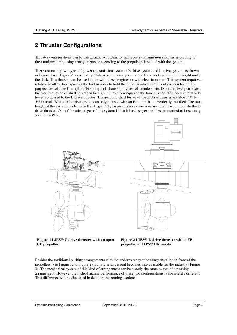
2 Thruster Configurations Thruster configurations can be categorized according to their power transmission systems, according to their underwater housing arrangements or according to the propulsors installed with the system. There are mainly two types of power transmission systems: Z-drive system and L-drive system, as shown in Figure 1 and Figure 2 respectively. Z-drive is the most popular one for vessels with limited height under the deck. This thruster can be used either with diesel engines or with electric motors. This system requires a relative small vertical space in the hull in order to hold the upper gearbox and it is often seen for multi-purpose vessels like fire fighter (FiFi) tugs, offshore supply vessels, tenders, etc. Due to its two gearboxes, the total reduction of shaft speed can be high, but as a consequence the transmission efficiency is relatively lower compared to the L-drive thruster. The gear and shaft losses of the Z-drive thruster are about 4% to 5% in total. While an L-drive system can only be used with an E-motor that is vertically installed. The total height of the system inside the hull is large. Only larger offshore structures are able to accommodate the L-drive thruster. One of the advantages of this system is that it has less gear and less transmission losses (say about 2%-3%).
Figure 1 LIPS® Z-drive thruster with an open CP propeller
Figure 2 LIPS® L-drive thruster with a FP propeller in LIPS® HR nozzle
Besides the traditional pushing arrangements with the underwater gear housings installed in front of the propellers (see Figure 1and Figure 2), pulling arrangement becomes also available for the industry (Figure 3). The mechanical system of this kind of arrangement can be exactly the same as that of a pushing arrangement. However the hydrodynamic performance of these two configurations is completely different. This difference will be discussed in detail in the coming sections.
J. Dang & H. Laheij, WPNL Hydrodynamics Aspects of Steerable Thrusters
Dynamic Positioning Conference September 28-30, 2003 Page 5
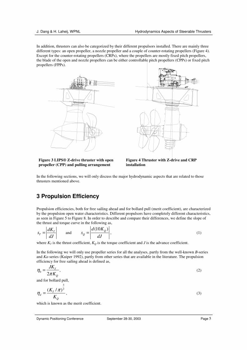
In addition, thrusters can also be categorized by their different propulsors installed. There are mainly three different types: an open propeller, a nozzle propeller and a couple of counter-rotating propellers (Figure 4). Except for the counter-rotating propellers (CRPs), where the propellers are mostly fixed pitch propellers, the blade of the open and nozzle propellers can be either controllable pitch propellers (CPPs) or fixed pitch propellers (FPPs).
Figure 3 LIPS® Z-drive thruster with open propeller (CPP) and pulling arrangement
Figure 4 Thruster with Z-drive and CRP installation
In the following sections, we will only discuss the major hydrodynamic aspects that are related to those thrusters mentioned above.
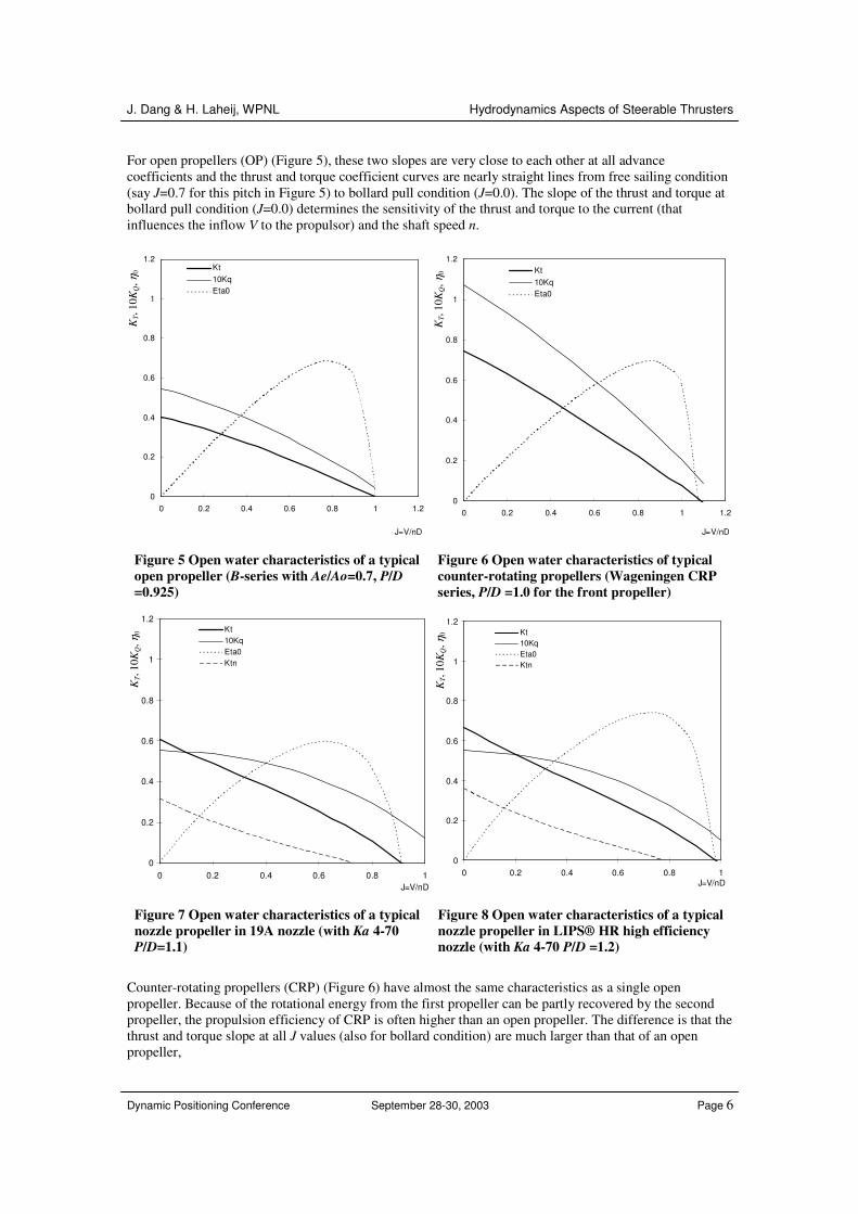
3 Propulsion Efficiency Propulsion efficiencies, both for free sailing ahead and for bollard pull (merit coefficient), are characterized by the propulsion open water characteristics. Different propulsors have completely different characteristics, as seen in Figure 5 to Figure 8. In order to describe and compare their differences, we define the slope of the thrust and torque curve in the following as,
TT
dKs
dJ= and
(10 )QQ
d Ks
dJ= , (1)
where KT is the thrust coefficient, KQ is the torque coefficient and J is the advance coefficient. In the following we will only use propeller series for all the analyses, partly from the well-known B-series and Ka-series (Kuiper 1992), partly from other series that are available in the literature. The propulsion efficiency for free sailing ahead is defined as,
0 2T
Q
JKK
ηπ
= , (2)
and for bollard pull, 32( / )T
dQ
KK
πη = , (3)
which is known as the merit coefficient.
J. Dang & H. Laheij, WPNL Hydrodynamics Aspects of Steerable Thrusters
Dynamic Positioning Conference September 28-30, 2003 Page 6
For open propellers (OP) (Figure 5), these two slopes are very close to each other at all advance coefficients and the thrust and torque coefficient curves are nearly straight lines from free sailing condition (say J=0.7 for this pitch in Figure 5) to bollard pull condition (J=0.0). The slope of the thrust and torque at bollard pull condition (J=0.0) determines the sensitivity of the thrust and torque to the current (that influences the inflow V to the propulsor) and the shaft speed n.
0
0.2
0.4
0.6
0.8
1
1.2
0 0.2 0.4 0.6 0.8 1 1.2
J=V/nD
Kt,
10K
q, E
ta0
Kt10KqEta0
0
0.2
0.4
0.6
0.8
1
1.2
0 0.2 0.4 0.6 0.8 1 1.2
J=V/nD
Kt,
10K
q, E
ta0
Kt10KqEta0
Figure 5 Open water characteristics of a typical open propeller (B-series with Ae/Ao=0.7, P/D =0.925)
Figure 6 Open water characteristics of typical counter-rotating propellers (Wageningen CRP series, P/D =1.0 for the front propeller)
0
0.2
0.4
0.6
0.8
1
1.2
0 0.2 0.4 0.6 0.8 1J=V/nD
Kt,
10K
q, E
ta0
Kt10KqEta0Ktn
0
0.2
0.4
0.6
0.8
1
1.2
0 0.2 0.4 0.6 0.8 1J=V/nD
Kt,
10K
q, E
ta0
Kt10KqEta0Ktn
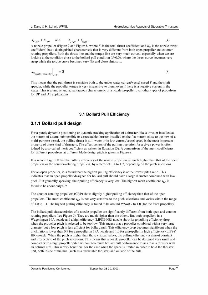
Figure 7 Open water characteristics of a typical nozzle propeller in 19A nozzle (with Ka 4-70 P/D=1.1)
Figure 8 Open water characteristics of a typical nozzle propeller in LIPS® HR high efficiency nozzle (with Ka 4-70 P/D =1.2)
Counter-rotating propellers (CRP) (Figure 6) have almost the same characteristics as a single open propeller. Because of the rotational energy from the first propeller can be partly recovered by the second propeller, the propulsion efficiency of CRP is often higher than an open propeller. The difference is that the thrust and torque slope at all J values (also for bollard condition) are much larger than that of an open propeller,
KT,
10K
Q, η
0
KT,
10K
Q, η
0
KT,
10K
Q, η
0
KT,
10K
Q, η
0
J. Dang & H. Laheij, WPNL Hydrodynamics Aspects of Steerable Thrusters
Dynamic Positioning Conference September 28-30, 2003 Page 7
T TCRP OPs s> and Q QCRP OPs s> . (4)
A nozzle propeller (Figure 7 and Figure 8, where Kt is the total thrust coefficient and Ktn is the nozzle thrust coefficient) has a distinguished characteristic that is very different from both open propeller and counter-rotating propellers. Both the thrust line and the torque line are very much curved, especially when we are looking at the condition close to the bollard pull condition (J=0.0), where the thrust curve becomes very steep while the torque curve becomes very flat and close almost to,
_ 00Qnozzle propeller J
s=
= . (5)
This means that the pull thrust is sensitive both to the under water current/vessel speed V and the shaft speed n, while the propeller torque is very insensitive to them, even if there is a negative current in the water. This is a unique and advantageous characteristic of a nozzle propeller over other types of propulsors for DP and DT applications.
3.1 Bollard Pull Efficiency
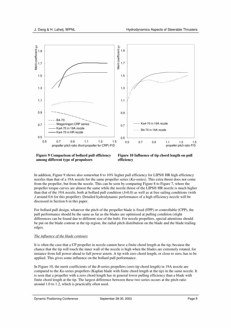
3.1.1 Bollard pull design For a purely dynamic positioning or dynamic tracking application of a thruster, like a thruster installed at the bottom of a semi-submersible or a retractable thruster installed on the flat bottom close to the bow of a multi-purpose vessel, the pulling thrust in still water or in low current/vessel speed is the most important property of these kind of thrusters. The effectiveness of the pulling operation for a given power is often judged by a so-called merit coefficient as written in Equation (3). A comparison of the merit coefficients for different propulsors at different blade design pitch is given in Figure 9. It is seen in Figure 9 that the pulling efficiency of the nozzle propellers is much higher than that of the open propellers or the counter-rotating propellers, by a factor of 1.4 to 1.7, depending on the pitch selections. For an open propeller, it is found that the highest pulling efficiency is at the lowest pitch ratio. This indicates that an open propeller designed for bollard pull should have a large diameter combined with low pitch. But generally speaking, their pulling efficiency is very low. The highest merit coefficient dη is found to be about only 0.9. The counter-rotating propellers (CRP) show slightly higher pulling efficiency than that of the open propellers. The merit coefficient dη is not very sensitive to the pitch selections and varies within the range of 1.0 to 1.1. The highest pulling efficiency is found to be around P/D=0.9 to 1.0 (for the front propeller). The bollard pull characteristics of a nozzle propeller are significantly different from both open and counter-rotating propellers (see Figure 9). They are much higher than the others. But both propellers in a Wageningen 19A nozzle and a high efficiency (LIPS® HR) nozzle show large pulling efficiency drop when the propeller pitch is selected to be too low. This means that a propeller combined with a very large diameter but a low pitch is less efficient for bollard pull. This efficiency drop becomes significant when the pitch ratio is lower than 0.9 for a propeller in 19A nozzle and 1.0 for a propeller in high efficiency (LIPS® HR) nozzle. When the pitch is higher than those critical values, the pulling efficiency is almost constant and irrespective of the pitch selections. This means that a nozzle propeller can be designed very small and compact with a high propeller pitch without too much bollard pull performance losses than a thruster with an optimal size. This is very beneficial for the case when the space is limited in order to hold the thruster unit, both inside of the hull (such as a retractable thruster) and outside of the hull.
J. Dang & H. Laheij, WPNL Hydrodynamics Aspects of Steerable Thrusters
Dynamic Positioning Conference September 28-30, 2003 Page 8
0.5
0.7
0.9
1.1
1.3
1.5
1.7
1.9
0.5 0.7 0.9 1.1 1.3 1.5propeller pitch ratio (front propeller for CRP) P/D
Mer
it co
effic
ient
ηd
B4-70Wageningen CRP series Ka4-70 in 19A nozzleKa4-70 in HR nozzle
0.5
0.7
0.9
1.1
1.3
1.5
1.7
1.9
0.5 0.7 0.9 1.1 1.3 1.5propeller pitch ratio P/D
Mer
it co
effic
ient
ηd
Ka4-70 in 19A nozzle
B4-70 in 19A nozzle
Figure 9 Comparison of bollard pull efficiency among different type of propulsors
Figure 10 Influence of tip chord length on pull efficiency
In addition, Figure 9 shows also somewhat 8 to 10% higher pull efficiency for LIPS® HR high efficiency nozzles than that of a 19A nozzle for the same propeller series (Ka-series). This extra thrust does not come from the propeller, but from the nozzle. This can be seen by comparing Figure 8 to Figure 7, where the propeller torque curves are almost the same while the nozzle thrust of the LIPS® HR nozzle is much higher than that of the 19A nozzle, both at bollard pull condition (J=0.0) as well as at free sailing conditions (with J around 0.6 for this propeller). Detailed hydrodynamic performance of a high efficiency nozzle will be discussed in Section 6 in this paper. For bollard pull design, whatever the pitch of the propeller blade is fixed (FPP) or controllable (CPP), the pull performance should be the same as far as the blades are optimized at pulling condition (slight differences can be found due to different size of the hub). For nozzle propellers, special attentions should be put on the blade contour at the tip region, the radial pitch distribution on the blade and the blade trailing edges. The influence of the blade contours It is often the case that a CP propeller in nozzle cannot have a finite chord length at the tip, because the chance that the tip will touch the inner wall of the nozzle is high when the blades are extremely rotated, for instance from full power ahead to full power astern. A tip with zero chord length, or close to zero, has to be applied. This gives some influence on the bollard pull performance. In Figure 10, the merit coefficients of the B-series propellers (zero tip chord length) in 19A nozzle are compared to the Ka-series propellers (Kaplan blade with finite chord length at the tip) in the same nozzle. It is seen that a propeller with a zero chord length has in general lower pulling efficiency than a blade with finite chord length at the tip. The largest difference between these two series occurs at the pitch ratio around 1.0 to 1.2, which is practically often used.
J. Dang & H. Laheij, WPNL Hydrodynamics Aspects of Steerable Thrusters
Dynamic Positioning Conference September 28-30, 2003 Page 9
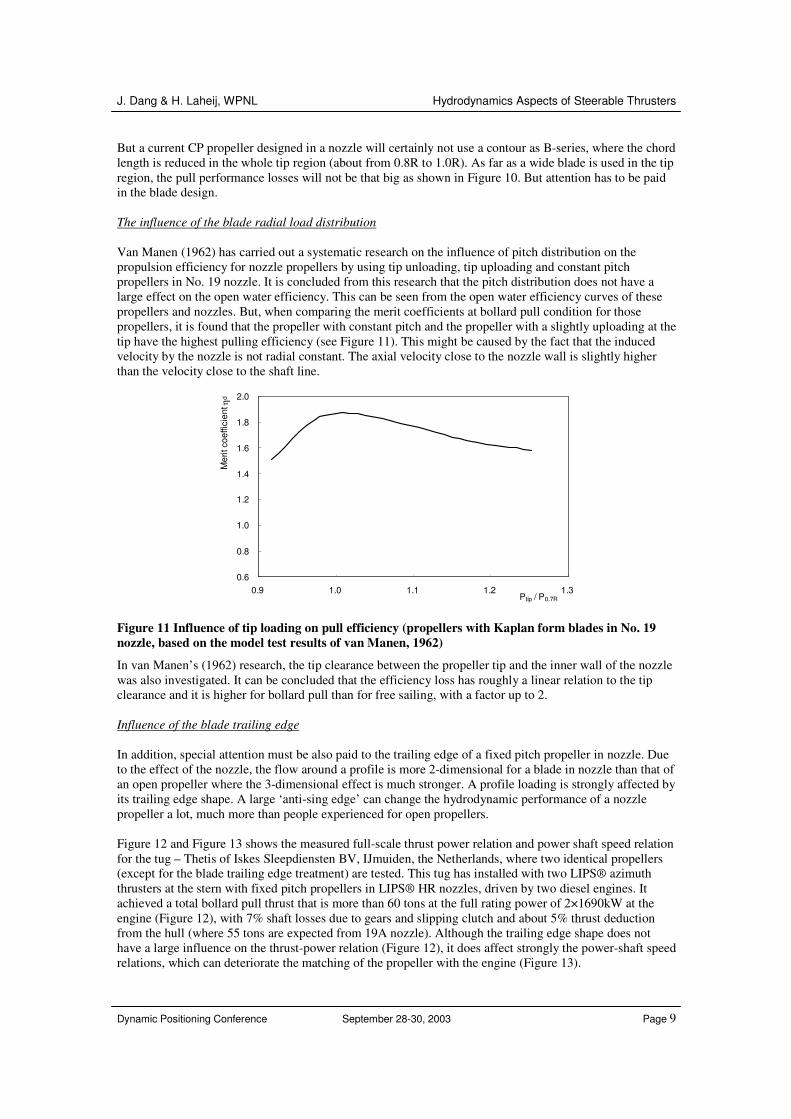
But a current CP propeller designed in a nozzle will certainly not use a contour as B-series, where the chord length is reduced in the whole tip region (about from 0.8R to 1.0R). As far as a wide blade is used in the tip region, the pull performance losses will not be that big as shown in Figure 10. But attention has to be paid in the blade design. The influence of the blade radial load distribution Van Manen (1962) has carried out a systematic research on the influence of pitch distribution on the propulsion efficiency for nozzle propellers by using tip unloading, tip uploading and constant pitch propellers in No. 19 nozzle. It is concluded from this research that the pitch distribution does not have a large effect on the open water efficiency. This can be seen from the open water efficiency curves of these propellers and nozzles. But, when comparing the merit coefficients at bollard pull condition for those propellers, it is found that the propeller with constant pitch and the propeller with a slightly uploading at the tip have the highest pulling efficiency (see Figure 11). This might be caused by the fact that the induced velocity by the nozzle is not radial constant. The axial velocity close to the nozzle wall is slightly higher than the velocity close to the shaft line.
0.6
0.8
1.0
1.2
1.4
1.6
1.8
2.0
0.9 1.0 1.1 1.2 1.3Ptip / P0.7R
Mer
it co
effic
ient
ηd
Figure 11 Influence of tip loading on pull efficiency (propellers with Kaplan form blades in No. 19 nozzle, based on the model test results of van Manen, 1962)
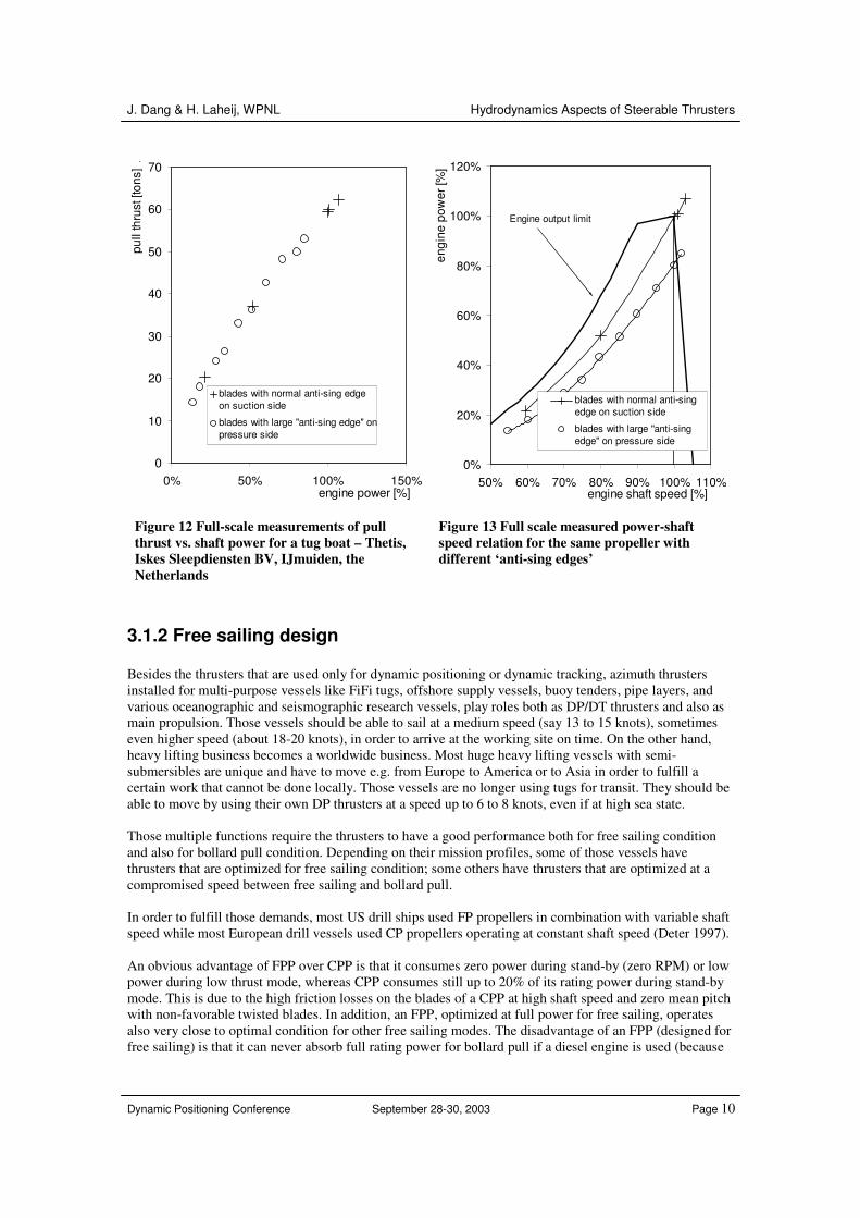
In van Manen’s (1962) research, the tip clearance between the propeller tip and the inner wall of the nozzle was also investigated. It can be concluded that the efficiency loss has roughly a linear relation to the tip clearance and it is higher for bollard pull than for free sailing, with a factor up to 2. Influence of the blade trailing edge In addition, special attention must be also paid to the trailing edge of a fixed pitch propeller in nozzle. Due to the effect of the nozzle, the flow around a profile is more 2-dimensional for a blade in nozzle than that of an open propeller where the 3-dimensional effect is much stronger. A profile loading is strongly affected by its trailing edge shape. A large ‘anti-sing edge’ can change the hydrodynamic performance of a nozzle propeller a lot, much more than people experienced for open propellers. Figure 12 and Figure 13 shows the measured full-scale thrust power relation and power shaft speed relation for the tug – Thetis of Iskes Sleepdiensten BV, IJmuiden, the Netherlands, where two identical propellers (except for the blade trailing edge treatment) are tested. This tug has installed with two LIPS® azimuth thrusters at the stern with fixed pitch propellers in LIPS® HR nozzles, driven by two diesel engines. It achieved a total bollard pull thrust that is more than 60 tons at the full rating power of 2×1690kW at the engine (Figure 12), with 7% shaft losses due to gears and slipping clutch and about 5% thrust deduction from the hull (where 55 tons are expected from 19A nozzle). Although the trailing edge shape does not have a large influence on the thrust-power relation (Figure 12), it does affect strongly the power-shaft speed relations, which can deteriorate the matching of the propeller with the engine (Figure 13).
J. Dang & H. Laheij, WPNL Hydrodynamics Aspects of Steerable Thrusters
Dynamic Positioning Conference September 28-30, 2003 Page 10
0
10
20
30
40
50
60
70
0% 50% 100% 150%engine power [%]
pull
thru
st [t
ons]
.
blades with normal anti-sing edgeon suction side
blades with large ''anti-sing edge'' onpressure side
0%
20%
40%
60%
80%
100%
120%
50% 60% 70% 80% 90% 100% 110%engine shaft speed [%]
engi
ne p
ower
[%]
blades with normal anti-singedge on suction side
blades with large ''anti-singedge'' on pressure side
Engine output limit
Figure 12 Full-scale measurements of pull thrust vs. shaft power for a tug boat – Thetis, Iskes Sleepdiensten BV, IJmuiden, the Netherlands
Figure 13 Full scale measured power-shaft speed relation for the same propeller with different ‘anti-sing edges’
3.1.2 Free sailing design Besides the thrusters that are used only for dynamic positioning or dynamic tracking, azimuth thrusters installed for multi-purpose vessels like FiFi tugs, offshore supply vessels, buoy tenders, pipe layers, and various oceanographic and seismographic research vessels, play roles both as DP/DT thrusters and also as main propulsion. Those vessels should be able to sail at a medium speed (say 13 to 15 knots), sometimes even higher speed (about 18-20 knots), in order to arrive at the working site on time. On the other hand, heavy lifting business becomes a worldwide business. Most huge heavy lifting vessels with semi-submersibles are unique and have to move e.g. from Europe to America or to Asia in order to fulfill a certain work that cannot be done locally. Those vessels are no longer using tugs for transit. They should be able to move by using their own DP thrusters at a speed up to 6 to 8 knots, even if at high sea state. Those multiple functions require the thrusters to have a good performance both for free sailing condition and also for bollard pull condition. Depending on their mission profiles, some of those vessels have thrusters that are optimized for free sailing condition; some others have thrusters that are optimized at a compromised speed between free sailing and bollard pull. In order to fulfill those demands, most US drill ships used FP propellers in combination with variable shaft speed while most European drill vessels used CP propellers operating at constant shaft speed (Deter 1997). An obvious advantage of FPP over CPP is that it consumes zero power during stand-by (zero RPM) or low power during low thrust mode, whereas CPP consumes still up to 20% of its rating power during stand-by mode. This is due to the high friction losses on the blades of a CPP at high shaft speed and zero mean pitch with non-favorable twisted blades. In addition, an FPP, optimized at full power for free sailing, operates also very close to optimal condition for other free sailing modes. The disadvantage of an FPP (designed for free sailing) is that it can never absorb full rating power for bollard pull if a diesel engine is used (because
J. Dang & H. Laheij, WPNL Hydrodynamics Aspects of Steerable Thrusters
Dynamic Positioning Conference September 28-30, 2003 Page 11
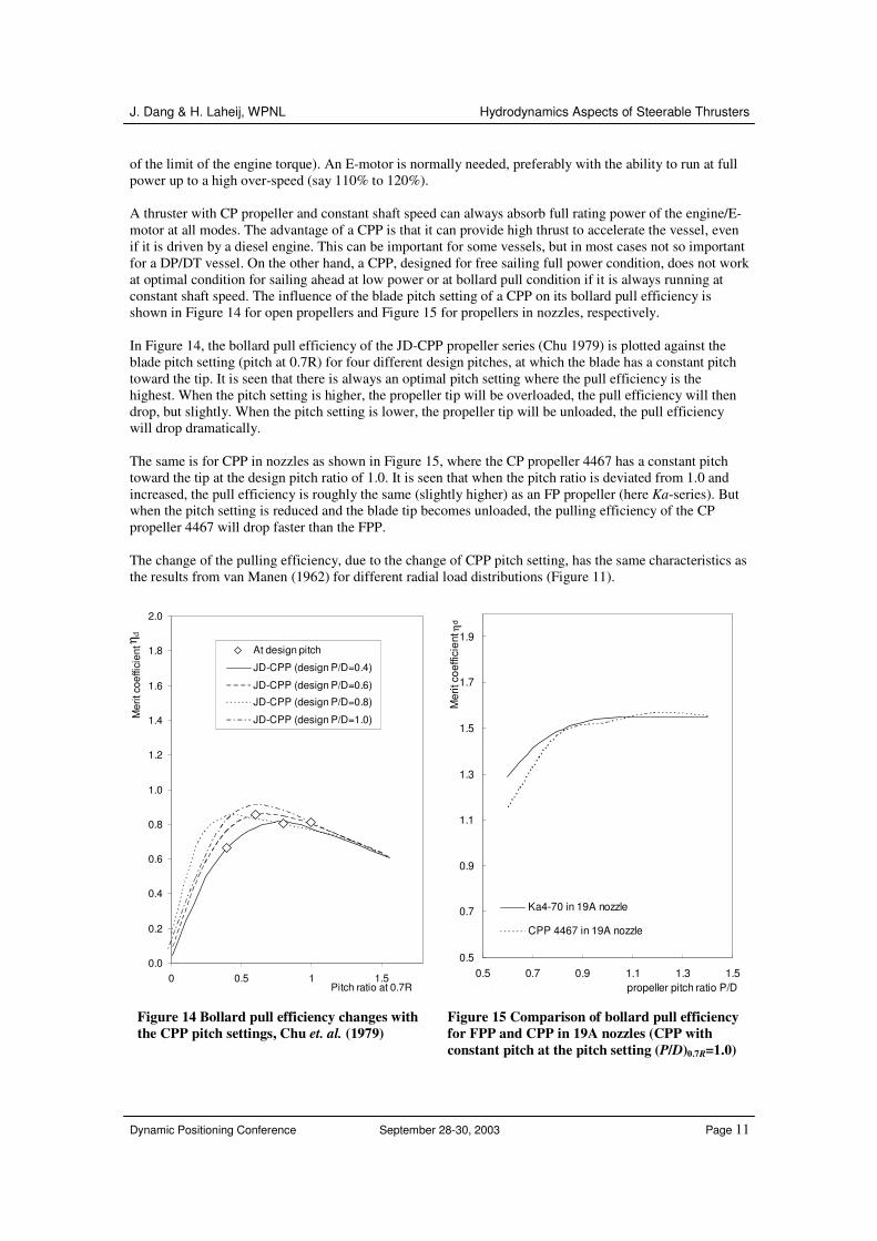
of the limit of the engine torque). An E-motor is normally needed, preferably with the ability to run at full power up to a high over-speed (say 110% to 120%). A thruster with CP propeller and constant shaft speed can always absorb full rating power of the engine/E-motor at all modes. The advantage of a CPP is that it can provide high thrust to accelerate the vessel, even if it is driven by a diesel engine. This can be important for some vessels, but in most cases not so important for a DP/DT vessel. On the other hand, a CPP, designed for free sailing full power condition, does not work at optimal condition for sailing ahead at low power or at bollard pull condition if it is always running at constant shaft speed. The influence of the blade pitch setting of a CPP on its bollard pull efficiency is shown in Figure 14 for open propellers and Figure 15 for propellers in nozzles, respectively. In Figure 14, the bollard pull efficiency of the JD-CPP propeller series (Chu 1979) is plotted against the blade pitch setting (pitch at 0.7R) for four different design pitches, at which the blade has a constant pitch toward the tip. It is seen that there is always an optimal pitch setting where the pull efficiency is the highest. When the pitch setting is higher, the propeller tip will be overloaded, the pull efficiency will then drop, but slightly. When the pitch setting is lower, the propeller tip will be unloaded, the pull efficiency will drop dramatically. The same is for CPP in nozzles as shown in Figure 15, where the CP propeller 4467 has a constant pitch toward the tip at the design pitch ratio of 1.0. It is seen that when the pitch ratio is deviated from 1.0 and increased, the pull efficiency is roughly the same (slightly higher) as an FP propeller (here Ka-series). But when the pitch setting is reduced and the blade tip becomes unloaded, the pulling efficiency of the CP propeller 4467 will drop faster than the FPP. The change of the pulling efficiency, due to the change of CPP pitch setting, has the same characteristics as the results from van Manen (1962) for different radial load distributions (Figure 11).
0.0
0.2
0.4
0.6
0.8
1.0
1.2
1.4
1.6
1.8
2.0
0 0.5 1 1.5Pitch ratio at 0.7R
Mer
it co
effic
ient
Eta
_d .
At design pitch
JD-CPP (design P/D=0.4)
JD-CPP (design P/D=0.6)
JD-CPP (design P/D=0.8)
JD-CPP (design P/D=1.0)
0.5
0.7
0.9
1.1
1.3
1.5
1.7
1.9
0.5 0.7 0.9 1.1 1.3 1.5propeller pitch ratio P/D
Mer
it co
effic
ient
ηd
Ka4-70 in 19A nozzle
CPP 4467 in 19A nozzle
Figure 14 Bollard pull efficiency changes with the CPP pitch settings, Chu et. al. (1979)
Figure 15 Comparison of bollard pull efficiency for FPP and CPP in 19A nozzles (CPP with constant pitch at the pitch setting (P/D)0.7R=1.0)
η d
J. Dang & H. Laheij, WPNL Hydrodynamics Aspects of Steerable Thrusters
Dynamic Positioning Conference September 28-30, 2003 Page 12
3.2 Free Sailing Efficiency
As has been discussed in the last section that most DP/DT azimuth thrusters are used nowadays also as the main propulsion for the vessel for free sailing. As far as the vessel sails a lot in its life from place to place, free sailing efficiency is also an important factor in selecting the suitable thruster units. An open propeller has the advantage of its simple form, low manufacturing cost and high reliability. But the free sailing efficiency of a counter-rotating propeller can be 10% higher than an open propeller. On the other hand, when the propeller is heavy loaded, it has been shown that a nozzle propeller (mainly 19A nozzle) is much more efficient than an open propeller (Oosterveld et. al. 1972) or even counter-rotating propellers. In the last two decades, various high efficiency nozzles are developed (Gruzling 2004), aiming at improving both bollard pull performance and also free sailing efficiency. After more than 10 years of experience and more than hundreds of applications at WPNL, the LIPS® HR high efficiency nozzle has been proven in practice to be able to improve both bollard pull and free sailing efficiency up to 10%. At the same time, thrusters with counter-rotating propellers (CRP) became also available in the market with various versions. A standard CRP thruster has two propellers rotating against each other at one side of the gear housing and close to each other (as shown in Figure 4). CRPs can be also installed at the two ends of the gear housing with a large distance in between. Propulsion system with a combined conventional propeller with a counter-rotating POD propeller (close to each other) is in fast development (Praefke 2001). It is always difficult to generalize which propulsion concept is superior to or inferior to the others. But for practical applications, especially when we are restricting our discussion within DP/DT related thruster applications, it becomes possible to make a comparison among those different concepts. This comparison can be essentially important for the yards and the owner to make decisions on which system would be the most suitable one for their specific task.
3.2.1 Open water efficiency In order to eliminate the influence of the shaft speed and the propeller diameter on the propeller open water efficiency, all comparisons in the following are made based on the propeller thrust load coefficient, defined as,
2
8 tt
KC
Jπ= , (6)
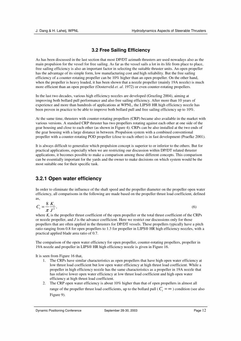
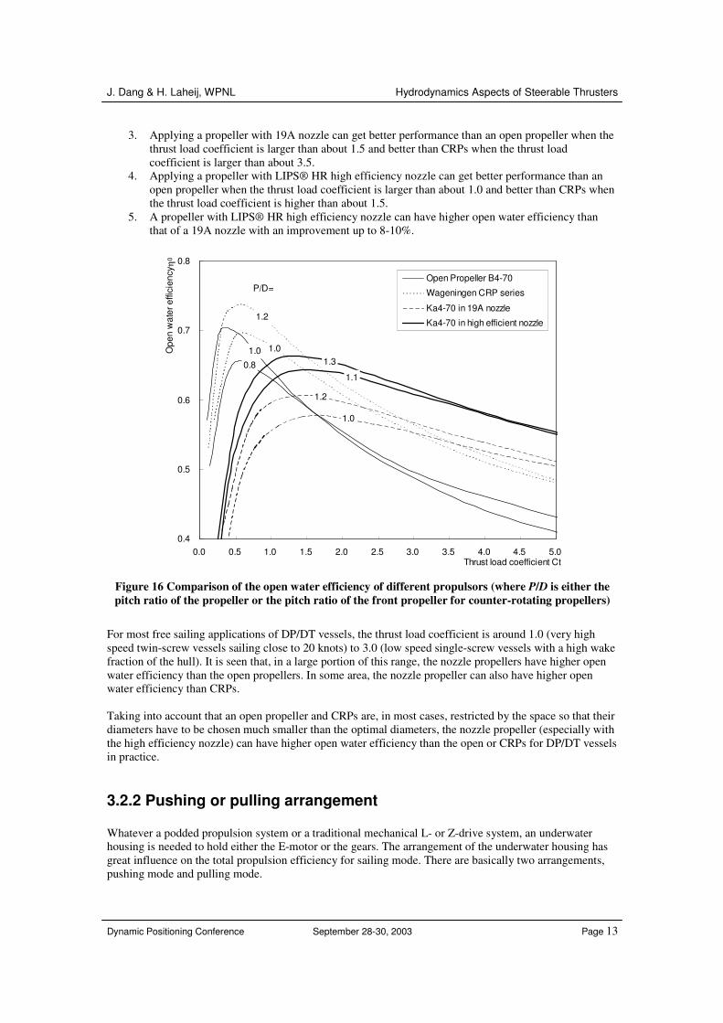
where Kt is the propeller thrust coefficient of the open propeller or the total thrust coefficient of the CRPs or nozzle propeller, and J is the advance coefficient. Here we restrict our discussions only for those propellers that are often applied in the thrusters for DP/DT vessels. These propellers typically have a pitch ratio ranging from 0.8 for open propellers to 1.3 for propeller in LIPS® HR high efficiency nozzles, with a practical applied blade area ratio of 0.7. The comparison of the open water efficiency for open propeller, counter-rotating propellers, propeller in 19A nozzle and propeller in LIPS® HR high efficiency nozzle is given in Figure 16. It is seen from Figure 16 that,
1. The CRPs have similar characteristics as open propellers that have high open water efficiency at low thrust load coefficient but low open water efficiency at high thrust load coefficient. While a propeller in high efficiency nozzle has the same characteristics as a propeller in 19A nozzle that has relative lower open water efficiency at low thrust load coefficient and high open water efficiency at high thrust load coefficient.
2. The CRP open water efficiency is about 10% higher than that of open propellers in almost all range of the propeller thrust load coefficients, up to the bollard pull ( tC = ∞ ) condition (see also Figure 9).
J. Dang & H. Laheij, WPNL Hydrodynamics Aspects of Steerable Thrusters
Dynamic Positioning Conference September 28-30, 2003 Page 13
3. Applying a propeller with 19A nozzle can get better performance than an open propeller when the thrust load coefficient is larger than about 1.5 and better than CRPs when the thrust load coefficient is larger than about 3.5.
4. Applying a propeller with LIPS® HR high efficiency nozzle can get better performance than an open propeller when the thrust load coefficient is larger than about 1.0 and better than CRPs when the thrust load coefficient is higher than about 1.5.
5. A propeller with LIPS® HR high efficiency nozzle can have higher open water efficiency than that of a 19A nozzle with an improvement up to 8-10%.
0.8
1.0 1.0
1.2
1.0
1.2
1.1
1.3
0.4
0.5
0.6
0.7
0.8
0.0 0.5 1.0 1.5 2.0 2.5 3.0 3.5 4.0 4.5 5.0Thrust load coefficient Ct
Ope
n w
ater
effi
cien
cy η0
Open Propeller B4-70
Wageningen CRP series
Ka4-70 in 19A nozzle
Ka4-70 in high efficient nozzle
P/D=
Figure 16 Comparison of the open water efficiency of different propulsors (where P/D is either the pitch ratio of the propeller or the pitch ratio of the front propeller for counter-rotating propellers)
For most free sailing applications of DP/DT vessels, the thrust load coefficient is around 1.0 (very high speed twin-screw vessels sailing close to 20 knots) to 3.0 (low speed single-screw vessels with a high wake fraction of the hull). It is seen that, in a large portion of this range, the nozzle propellers have higher open water efficiency than the open propellers. In some area, the nozzle propeller can also have higher open water efficiency than CRPs. Taking into account that an open propeller and CRPs are, in most cases, restricted by the space so that their diameters have to be chosen much smaller than the optimal diameters, the nozzle propeller (especially with the high efficiency nozzle) can have higher open water efficiency than the open or CRPs for DP/DT vessels in practice.
3.2.2 Pushing or pulling arrangement Whatever a podded propulsion system or a traditional mechanical L- or Z-drive system, an underwater housing is needed to hold either the E-motor or the gears. The arrangement of the underwater housing has great influence on the total propulsion efficiency for sailing mode. There are basically two arrangements, pushing mode and pulling mode.
J. Dang & H. Laheij, WPNL Hydrodynamics Aspects of Steerable Thrusters
Dynamic Positioning Conference September 28-30, 2003 Page 14
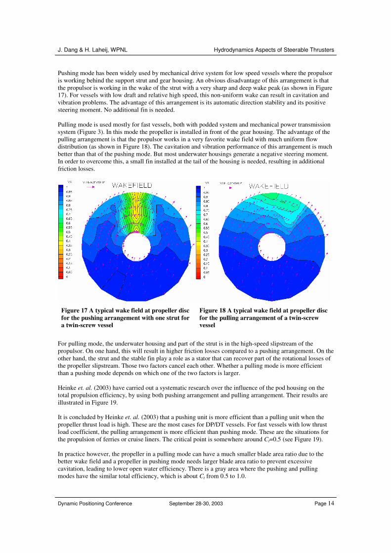
Pushing mode has been widely used by mechanical drive system for low speed vessels where the propulsor is working behind the support strut and gear housing. An obvious disadvantage of this arrangement is that the propulsor is working in the wake of the strut with a very sharp and deep wake peak (as shown in Figure 17). For vessels with low draft and relative high speed, this non-uniform wake can result in cavitation and vibration problems. The advantage of this arrangement is its automatic direction stability and its positive steering moment. No additional fin is needed. Pulling mode is used mostly for fast vessels, both with podded system and mechanical power transmission system (Figure 3). In this mode the propeller is installed in front of the gear housing. The advantage of the pulling arrangement is that the propulsor works in a very favorite wake field with much uniform flow distribution (as shown in Figure 18). The cavitation and vibration performance of this arrangement is much better than that of the pushing mode. But most underwater housings generate a negative steering moment. In order to overcome this, a small fin installed at the tail of the housing is needed, resulting in additional friction losses.
Figure 17 A typical wake field at propeller disc for the pushing arrangement with one strut for a twin-screw vessel
Figure 18 A typical wake field at propeller disc for the pulling arrangement of a twin-screw vessel
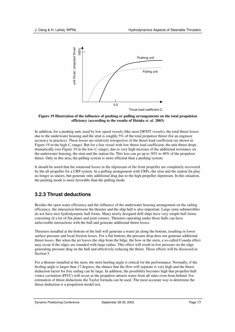
For pulling mode, the underwater housing and part of the strut is in the high-speed slipstream of the propulsor. On one hand, this will result in higher friction losses compared to a pushing arrangement. On the other hand, the strut and the stable fin play a role as a stator that can recover part of the rotational losses of the propeller slipstream. Those two factors cancel each other. Whether a pulling mode is more efficient than a pushing mode depends on which one of the two factors is larger. Heinke et. al. (2003) have carried out a systematic research over the influence of the pod housing on the total propulsion efficiency, by using both pushing arrangement and pulling arrangement. Their results are illustrated in Figure 19. It is concluded by Heinke et. al. (2003) that a pushing unit is more efficient than a pulling unit when the propeller thrust load is high. These are the most cases for DP/DT vessels. For fast vessels with low thrust load coefficient, the pulling arrangement is more efficient than pushing mode. These are the situations for the propulsion of ferries or cruise liners. The critical point is somewhere around Ct=0.5 (see Figure 19). In practice however, the propeller in a pulling mode can have a much smaller blade area ratio due to the better wake field and a propeller in pushing mode needs larger blade area ratio to prevent excessive cavitation, leading to lower open water efficiency. There is a gray area where the pushing and pulling modes have the similar total efficiency, which is about Ct from 0.5 to 1.0.
J. Dang & H. Laheij, WPNL Hydrodynamics Aspects of Steerable Thrusters
Dynamic Positioning Conference September 28-30, 2003 Page 15
0.5 Thrust load coefficient Ct
unit
thru
st /
prop
ulso
r thr
ust
100%
Pulling unit
Pushing unit
Figure 19 Illustration of the influence of pushing or pulling arrangements on the total propulsion efficiency (according to the results of Heinke et. al. 2003)
In addition, for a pushing unit, used by low speed vessels (like most DP/DT vessels), the total thrust losses due to the underwater housing and the strut is roughly 5% of the total propulsor thrust (for an engineer accuracy in practice). These losses are relatively irrespective of the thrust load coefficient (as shown in Figure 19 in the high Ct range). But for a fast vessel with low thrust load coefficient, the unit thrust drops dramatically (see Figure 19 in the low Ct range), due to very high increase of the additional resistance on the underwater housing, the strut and the station fin. This loss can go up to 30% to 40% of the propulsor thrust. Only in this area, the pulling system is more efficient than a pushing system. It should be noted that the rotational losses in the slipstream of the front propeller are completely recovered by the aft propeller for a CRP system. In a pulling arrangement with CRPs, the strut and the station fin play no longer as stators, but generate only additional drag due to the high propeller slipstream. In this situation, the pushing mode is more favorable than the pulling mode.
3.2.3 Thrust deductions Besides the open water efficiency and the influence of the underwater housing arrangement on the sailing efficiency, the interaction between the thruster and the ship hull is also important. Large semi-submersibles do not have nice hydrodynamic hull forms. Many newly designed drill ships have very simple hull forms consisting of a lot of flat plates and joint corners. Thrusters operating under those hulls can have unfavorable interactions with the hull and generate additional thrust losses. Thrusters installed at the bottom of the hull will generate a water jet along the bottom, resulting in lower surface pressure and local friction losses. For a flat bottom, the pressure drop does not generate additional thrust losses. But when the jet leaves the ship from the bilge, the bow or the stern, a so-called Coanda effect may occur if the edges are rounded with large radius. This effect will result in low pressure on the edge generating pressure drag on the hull and effectively reducing the thrust. Those effects will be discussed in Section 5. For a thruster installed at the stern, the stern heeling angle is critical for the performance. Normally, if the heeling angle is larger than 17 degrees, the chance that the flow will separate is very high and the thrust deduction factor for free sailing can be large. In addition, the possibility becomes high that propeller-hull vortex cavitation (PIVC) will occur as the propulsor attracts water from all sides even from behind. For estimation of thrust deductions the Taylor formula can be used. The most accurate way to determine the thrust deduction is a propulsion model test.

J. Dang & H. Laheij, WPNL Hydrodynamics Aspects of Steerable Thrusters
Dynamic Positioning Conference September 28-30, 2003 Page 16
In addition, a large heeling angle will also result in large pull thrust losses. The relation between heeling angle and the thrust deduction is given by van Beek et. al. (2002) and shown in Figure 20 in the following.
0.03
0.04
0.05
0.06
0.07
0.08
0.09
0.1
0.11
0.12
10 12 14 16 18 20 22 24stern heeling angle [degrees]
thru
st d
educ
tion
t
Figure 20 Thrust deductions for bollard pull condition at different stern heeling angles (van Beek et. al. 2002)
4 Matching with the engine / E-motor For thrusters with controllable pitch propellers, the propeller pitch can always be changed in order to absorb a certain amount of power at given engine/E-motor shaft speed. In this way, the propulsors match always their engine/E-motor properties, whatever at DP/DT condition or at free sailing condition. In the following, thrusters with CPPs will not be discussed. A fixed pitch propeller has a very rigid property. Its pitch is fixed. When either the entrant water speed to the propeller (due to sailing speed or current) or the shaft speed is changed, the shaft power changes also. On the other hand, it can happen that the propeller can not absorb the full rating power of the engine simply because the shaft torque reaches the limit very early at a low RPM. In such a situation, the propeller is too heavy. It can also happen that a propeller is too light if the shaft speed reaches the mechanical limit of the engine/E-motor but the shaft power is still much lower than its maximum rating power. This kind of problem can occur for DP/DT applications because the operation modes vary a lot. A diesel engine cannot easily handle it. A medium speed diesel engine is not allowed to operate at over-speed and the shaft torque can not remain maximum at low shaft speed. An E-motor is often demanded because an E-motor can reach the maximal torque at very low shaft speed and it can be easily designed to run up to 120% over-speed or even higher. With the development of large AC E-motors, thrusters with a fixed pitch propeller and diesel-electric drive become more and more popular for DP/DT vessels. On the other hand, different propulsion concepts with FPPs (open FPP, nozzle FPP or CRP) have different characteristics in response to the engine/E-motor’s properties. These differences can be explained by their different open water characteristics as shown in Figure 5 to Figure 8 at the beginning of Section 3. In the following we will take two typical DP vessels as examples to illustrate these differences.
J. Dang & H. Laheij, WPNL Hydrodynamics Aspects of Steerable Thrusters
Dynamic Positioning Conference September 28-30, 2003 Page 17
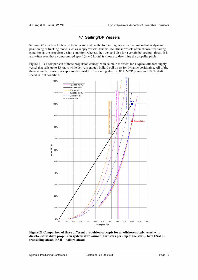
4.1 Sailing/DP Vessels Sailing/DP vessels refer here to those vessels where the free sailing mode is equal important as dynamic positioning or tracking mode, such as supply vessels, tenders, etc. Those vessels often choose free sailing condition as the propulsor design condition, whereas they demand also for a certain bollard pull thrust. It is also often seen that a compromised speed (4 to 6 knots) is chosen to determine the propeller pitch. Figure 21 is a comparison of three propulsion concept with azimuth thrusters for a typical offshore supply vessel that sails up to 13 knots while delivers enough bollard pull thrust for dynamic positioning. All of the three azimuth thruster concepts are designed for free sailing ahead at 85% MCR power and 100% shaft speed in trial condition.
0%
10%
20%
30%
40%
50%
60%
70%
80%
90%
100%
110%
120%
0% 10% 20% 30% 40% 50% 60% 70% 80% 90% 100% 110% 120%
shaft speed N [%]
pow
er P
B [%
]
FSAH FPP OPEN
FSAH FPP HR
FSAH CRP
BAH FPP OPEN
BAH FPP HR
BAH CRP
MCR
Design PointMax
. BA
H th
rust
(311
kN) a
t Max
. tor
que
Max
. BA
H th
rust
(366
kN) a
t Max
. tor
que
Max
. BA
H th
rust
(515
kN) a
t Max
. tor
que
Figure 21 Comparison of three different propulsion concepts for an offshore supply vessel with diesel-electric drive propulsion systems (two azimuth thrusters per ship at the stern), here FSAH - free sailing ahead, BAH – bollard ahead
J. Dang & H. Laheij, WPNL Hydrodynamics Aspects of Steerable Thrusters
Dynamic Positioning Conference September 28-30, 2003 Page 18
It is seen in Figure 21 that the propeller curves for all of the designs are very close to each other for free sailing condition (the solid lines), but very much apart for bollard pull condition for each concept (dashed lines).
• The propeller curve for a FPP in nozzle does not change that much for different conditions. The bollard pull curve is very close to the free sailing curve. This is because the torque curve in the open water diagrams (Figure 7 and Figure 8) is very insensitive to the advance coefficient. This makes the propulsor able to absorb almost full power for all conditions. The shaft speed difference from bollard pull to free sailing at pull power is typically 8 to 10%.
• An open fixed pitch propeller is sensitive to the operation conditions. Its free sailing curve is quite apart from its bollard pull curve (Figure 21). A shaft speed difference of 20 to 25% between bollard pull and free sailing conditions at full power is often seen.
• The most sensitive one is the CRP concept where the bollard pull curve is extremely apart to its free sailing curve (Figure 21). This is determined by its KT, KQ property as we discussed in Equation (4). A direct consequence is that the propeller can not generate enough pull thrust simply because it can not absorb the full rating power. A typical difference of 25% to 30% shaft speed is often seen.
In other words, if the thruster should be able to absorb always full power from bollard pull condition to free sailing condition, a CRP and an open FPP will demand for an E-motor that should be able to run an over-speed up to 130% and 125%, respectively. But an FPP in the nozzle asks for only 110%.
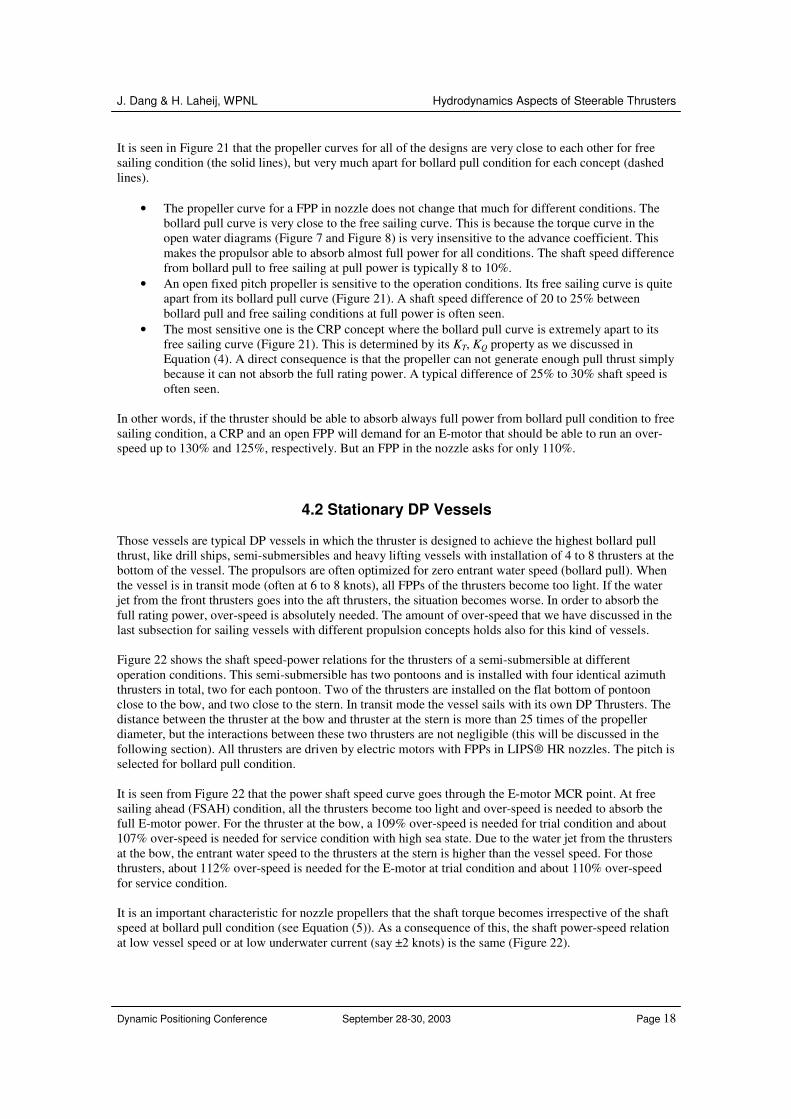
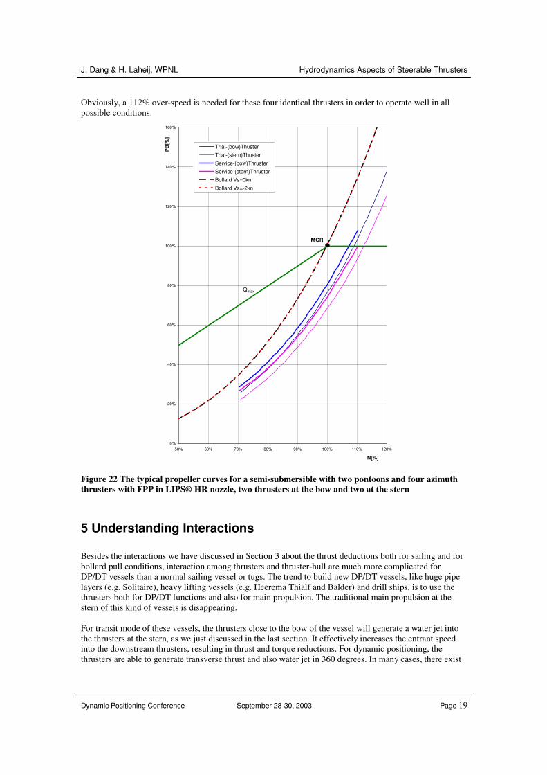
4.2 Stationary DP Vessels Those vessels are typical DP vessels in which the thruster is designed to achieve the highest bollard pull thrust, like drill ships, semi-submersibles and heavy lifting vessels with installation of 4 to 8 thrusters at the bottom of the vessel. The propulsors are often optimized for zero entrant water speed (bollard pull). When the vessel is in transit mode (often at 6 to 8 knots), all FPPs of the thrusters become too light. If the water jet from the front thrusters goes into the aft thrusters, the situation becomes worse. In order to absorb the full rating power, over-speed is absolutely needed. The amount of over-speed that we have discussed in the last subsection for sailing vessels with different propulsion concepts holds also for this kind of vessels. Figure 22 shows the shaft speed-power relations for the thrusters of a semi-submersible at different operation conditions. This semi-submersible has two pontoons and is installed with four identical azimuth thrusters in total, two for each pontoon. Two of the thrusters are installed on the flat bottom of pontoon close to the bow, and two close to the stern. In transit mode the vessel sails with its own DP Thrusters. The distance between the thruster at the bow and thruster at the stern is more than 25 times of the propeller diameter, but the interactions between these two thrusters are not negligible (this will be discussed in the following section). All thrusters are driven by electric motors with FPPs in LIPS® HR nozzles. The pitch is selected for bollard pull condition. It is seen from Figure 22 that the power shaft speed curve goes through the E-motor MCR point. At free sailing ahead (FSAH) condition, all the thrusters become too light and over-speed is needed to absorb the full E-motor power. For the thruster at the bow, a 109% over-speed is needed for trial condition and about 107% over-speed is needed for service condition with high sea state. Due to the water jet from the thrusters at the bow, the entrant water speed to the thrusters at the stern is higher than the vessel speed. For those thrusters, about 112% over-speed is needed for the E-motor at trial condition and about 110% over-speed for service condition. It is an important characteristic for nozzle propellers that the shaft torque becomes irrespective of the shaft speed at bollard pull condition (see Equation (5)). As a consequence of this, the shaft power-speed relation at low vessel speed or at low underwater current (say ±2 knots) is the same (Figure 22).
J. Dang & H. Laheij, WPNL Hydrodynamics Aspects of Steerable Thrusters
Dynamic Positioning Conference September 28-30, 2003 Page 19
Obviously, a 112% over-speed is needed for these four identical thrusters in order to operate well in all possible conditions.
0%
20%
40%
60%
80%
100%
120%
140%
160%
50% 60% 70% 80% 90% 100% 110% 120%
N[%]
PB
[%]
Trial-(bow)Thuster
Trial-(stern)Thuster
Service-(bow)Thruster
Service-(stern)Thruster
Bollard Vs=0kn
Bollard Vs=-2kn
MCR
Qmax
Figure 22 The typical propeller curves for a semi-submersible with two pontoons and four azimuth thrusters with FPP in LIPS® HR nozzle, two thrusters at the bow and two at the stern
5 Understanding Interactions Besides the interactions we have discussed in Section 3 about the thrust deductions both for sailing and for bollard pull conditions, interaction among thrusters and thruster-hull are much more complicated for DP/DT vessels than a normal sailing vessel or tugs. The trend to build new DP/DT vessels, like huge pipe layers (e.g. Solitaire), heavy lifting vessels (e.g. Heerema Thialf and Balder) and drill ships, is to use the thrusters both for DP/DT functions and also for main propulsion. The traditional main propulsion at the stern of this kind of vessels is disappearing. For transit mode of these vessels, the thrusters close to the bow of the vessel will generate a water jet into the thrusters at the stern, as we just discussed in the last section. It effectively increases the entrant speed into the downstream thrusters, resulting in thrust and torque reductions. For dynamic positioning, the thrusters are able to generate transverse thrust and also water jet in 360 degrees. In many cases, there exist
J. Dang & H. Laheij, WPNL Hydrodynamics Aspects of Steerable Thrusters
Dynamic Positioning Conference September 28-30, 2003 Page 20
critical angles when the jet of one thruster will hit the other thruster with large influences. Mostly, this should be avoided. If not completely, this interaction should at least be known. Due to the complexity of all iterations, there is still no good theory or calculation method available in order to predict accurately the interactions. Limited research results are available from model scale. Those model tests have been carried out at all of the most well-known institutes like MARIN in the Netherlands (Nienhuis 1992), HSVA in Germany (Blaurock 1977), SSPA in Sweden (Moberg et. al. 1983), NSFI in Norway (Lehn 1980) and NPL in England (English 1975). Although different thrusters with different propellers were used in the tests, the results show a very good agreement among those different tests. For practical application, some of the interactions can be summarized into simple formulae in order to make a prediction up to engineer accuracy. In order to have an accurate prediction for interactions, model tests have to be carried out.
5.1 Thruster Water Jet When the water jet leaves the thruster in infinite fluid, it expands with an angle of 8-10 degrees (Nienhuis 1992, English 1975). The maximum speed at the beginning is not at the shaft centerline but at the outer radii of the thrusters, forming a maximum speed ring. After about a distance of 4 to 6 thruster propeller diameters, the maximum speed becomes at the shaft centerline. Due to the expansion of the jet, the jet speed drops very fast. The maximum speed in the jet drops to half of the speed at the exit of the thruster after only 1 to 2 diameters (Nienhuis 1992). A thruster slipstream has some rotation, and it grows more quickly with penetration into the quiescent fluid than a plan free jet (English 1975). When the jet is discharged from a thruster close to a surface, the jet tends to adhere to a solid surface and grows rapidly in the plan rather than vertical to the plane. The center of the jet will deviate from the shaft line toward the surface. This will change the interactions between thrusters when they are under a flat bottom, comparing to thrusters in free water. When the surface is curved, the jet will follow the curved surface and results in pressure forces that are opposite to the thrust. This phenomenon is known as Coanda effect.
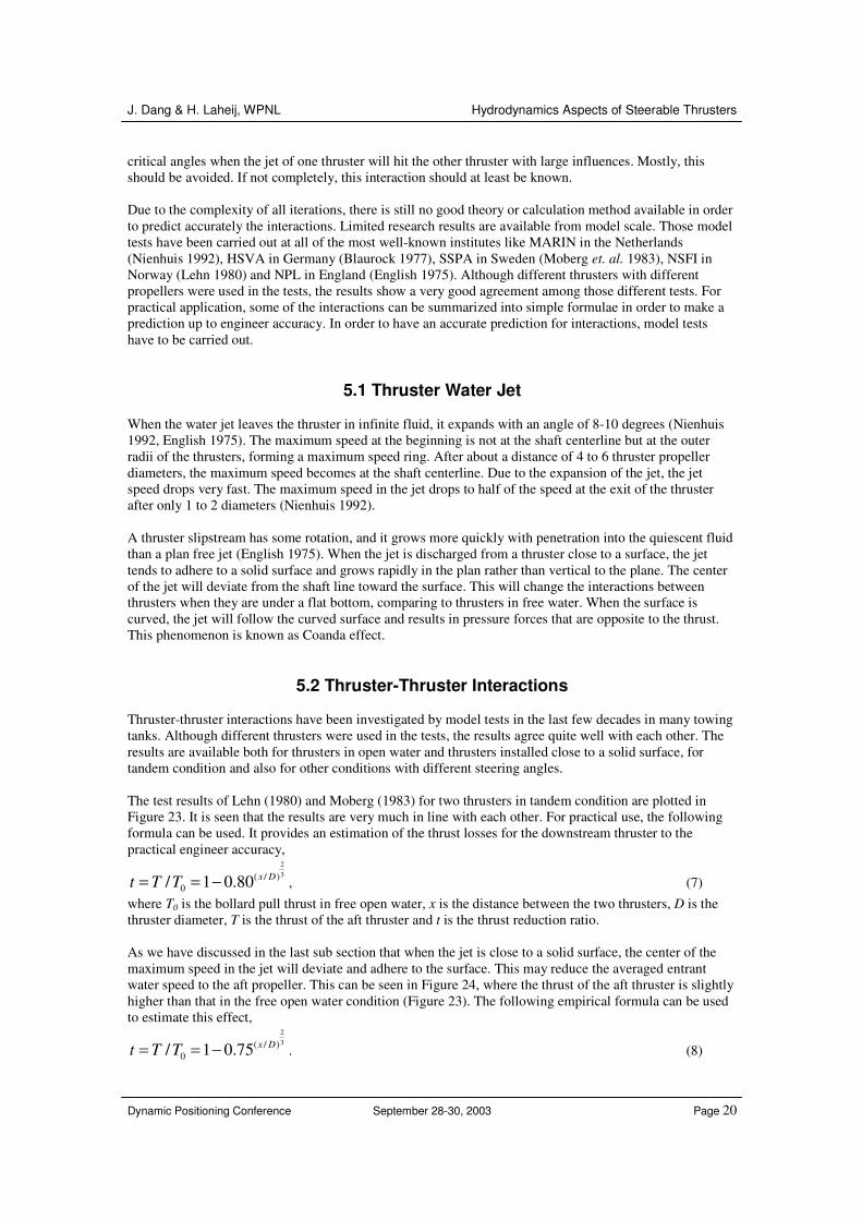
5.2 Thruster-Thruster Interactions Thruster-thruster interactions have been investigated by model tests in the last few decades in many towing tanks. Although different thrusters were used in the tests, the results agree quite well with each other. The results are available both for thrusters in open water and thrusters installed close to a solid surface, for tandem condition and also for other conditions with different steering angles. The test results of Lehn (1980) and Moberg (1983) for two thrusters in tandem condition are plotted in Figure 23. It is seen that the results are very much in line with each other. For practical use, the following formula can be used. It provides an estimation of the thrust losses for the downstream thruster to the practical engineer accuracy,
23( / )
0/ 1 0.80 x Dt T T= = − , (7) where T0 is the bollard pull thrust in free open water, x is the distance between the two thrusters, D is the thruster diameter, T is the thrust of the aft thruster and t is the thrust reduction ratio. As we have discussed in the last sub section that when the jet is close to a solid surface, the center of the maximum speed in the jet will deviate and adhere to the surface. This may reduce the averaged entrant water speed to the aft propeller. This can be seen in Figure 24, where the thrust of the aft thruster is slightly higher than that in the free open water condition (Figure 23). The following empirical formula can be used to estimate this effect,
23( / )
0/ 1 0.75 x Dt T T= = − . (8)
J. Dang & H. Laheij, WPNL Hydrodynamics Aspects of Steerable Thrusters
Dynamic Positioning Conference September 28-30, 2003 Page 21
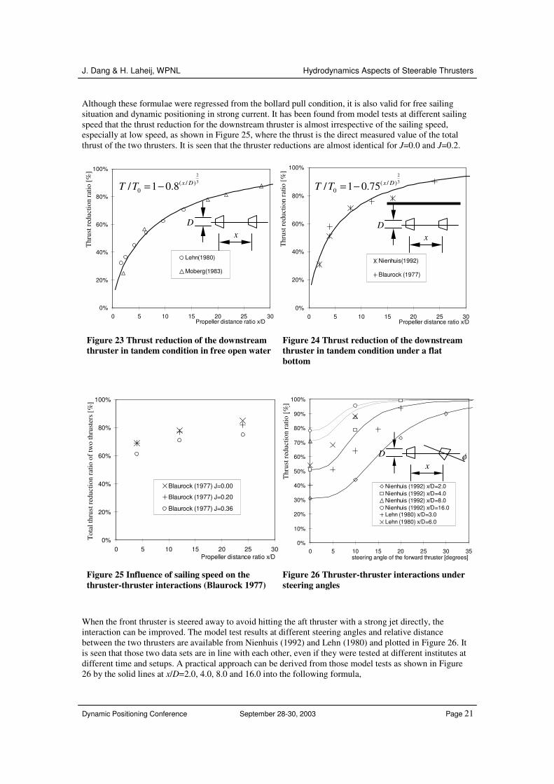
Although these formulae were regressed from the bollard pull condition, it is also valid for free sailing situation and dynamic positioning in strong current. It has been found from model tests at different sailing speed that the thrust reduction for the downstream thruster is almost irrespective of the sailing speed, especially at low speed, as shown in Figure 25, where the thrust is the direct measured value of the total thrust of the two thrusters. It is seen that the thruster reductions are almost identical for J=0.0 and J=0.2.
0%
20%
40%
60%
80%
100%
0 5 10 15 20 25 30Propeller distance ratio x/D
Thr
ust r
educ
tion
[%]
.
Lehn(1980)
Moberg(1983)
0%
20%
40%
60%
80%
100%
0 5 10 15 20 25 30Propeller distance ratio x/D
Thr
ust r
educ
tion
[%]
.
Nienhuis(1992)
Blaurock (1977)
Figure 23 Thrust reduction of the downstream thruster in tandem condition in free open water
Figure 24 Thrust reduction of the downstream thruster in tandem condition under a flat bottom
0%
20%
40%
60%
80%
100%
0 5 10 15 20 25 30Propeller distance ratio x/D
Tota
l thr
ust r
educ
tion
of tw
o th
rust
ers
[%]
.
Blaurock (1977) J=0.00
Blaurock (1977) J=0.20
Blaurock (1977) J=0.36
0%
10%
20%
30%
40%
50%
60%
70%
80%
90%
100%
0 5 10 15 20 25 30 35steering angle of the forward thruster [degrees]
Thr
ust d
educ
tion
[%]
.
Nienhuis (1992) x/D=2.0Nienhuis (1992) x/D=4.0Nienhuis (1992) x/D=8.0Nienhuis (1992) x/D=16.0Lehn (1980) x/D=3.0Lehn (1980) x/D=6.0
Figure 25 Influence of sailing speed on the thruster-thruster interactions (Blaurock 1977)
Figure 26 Thruster-thruster interactions under steering angles
When the front thruster is steered away to avoid hitting the aft thruster with a strong jet directly, the interaction can be improved. The model test results at different steering angles and relative distance between the two thrusters are available from Nienhuis (1992) and Lehn (1980) and plotted in Figure 26. It is seen that those two data sets are in line with each other, even if they were tested at different institutes at different time and setups. A practical approach can be derived from those model tests as shown in Figure 26 by the solid lines at x/D=2.0, 4.0, 8.0 and 16.0 into the following formula,
23( / )
0/ 1 0.8 x DT T = −23( / )
0/ 1 0.75 x DT T = −
x D
x D
x D φ
Thr
ust r
educ
tion
ratio
[%]
Thru
st re
duct
ion
ratio
[%]
Thr
ust r
educ
tion
ratio
[%]
Tot
al th
rust
redu
ctio
n ra
tio o
f tw
o th
rust
ers
[%]
J. Dang & H. Laheij, WPNL Hydrodynamics Aspects of Steerable Thrusters
Dynamic Positioning Conference September 28-30, 2003 Page 22
3
3 3(1 )130 /
t t ttφφ
φ= + −
+, (9)
where φ is the steering angle in degrees, t is the thrust reduction ratio at zero steering angle determined by Equation (7) or (8) and tφ is the thrust reduction ratio at steering angle φ for the aft thruster. Equation (7) to (9) provide the fast estimation for the thrust losses to a practical accuracy.
5.3 Thruster-Hull Interactions Different from the thruster-thruster interactions whereas systematic experiments were carried out and the results were very much in line with each other so that pragmatic formulae can be derived, thruster-hull interactions are much more complicated. These complications come from hull form and the installation orientation of the thrusters. For practice, the following interactions should be noted.
• When the thruster is installed under a flat bottom of a vessel, the water jet tends to adhere to the bottom surface and generate the friction force that is in opposite direction of the thrust, resulting in a thrust reduction. This reduction can be high and up to 20% to 25% (Blaurock 1977). A thruster installed at the bow is very inefficient for generating thrust in sailing direction, both for zero speed and for free sailing ahead.
• When the hull surface is curved with a large radius, like the bilge region, the jet flow can follow
the curved surface to a certain extend, resulting in low pressure area on the curved surface and a pressure drag that cancels part of the thrust, so-called Coanda effect. Systematic research has been done by Nienhuis (1992) by using a barge with different bilges and different bilge radii. It is found that: the larger the radius and the distance of the thruster to the bilge is, the stronger the Coanda effect and the pressure drag will be. This can result in a thrust reduction up to 15%.
• English (1975) found that the water jet could bend up to 29o when the thruster is installed very
close to the flat bottom of a vessel and far from its bilge with large radius. This angle is much larger than the normal expansion angle of a jet, e.g. 8 o to 10 o. When this happens to a semi-submersible with two pontoons, the jet can hit the sidewall of the hull completely. This can create un-expected total pulling thrust losses. Nienhuis (1992) measured a force on the second pontoon up to 8 to 12% of the thrust.
• For thrusters installed at the stern and also used as main propulsion, like thrusters in most offshore
supply vessels and FiFi tugs, the thrust deductions for ahead operation and astern operation are different. For ahead operation, the thrust deduction can be determined by Figure 20 (see also van Beek 2002). For astern operation, the water jet hits the hull directly. The thrust deduction is higher than the ahead operation. In practice, the astern thrust deduction is about two times larger than the ahead thrust deduction (van Beek 2002).
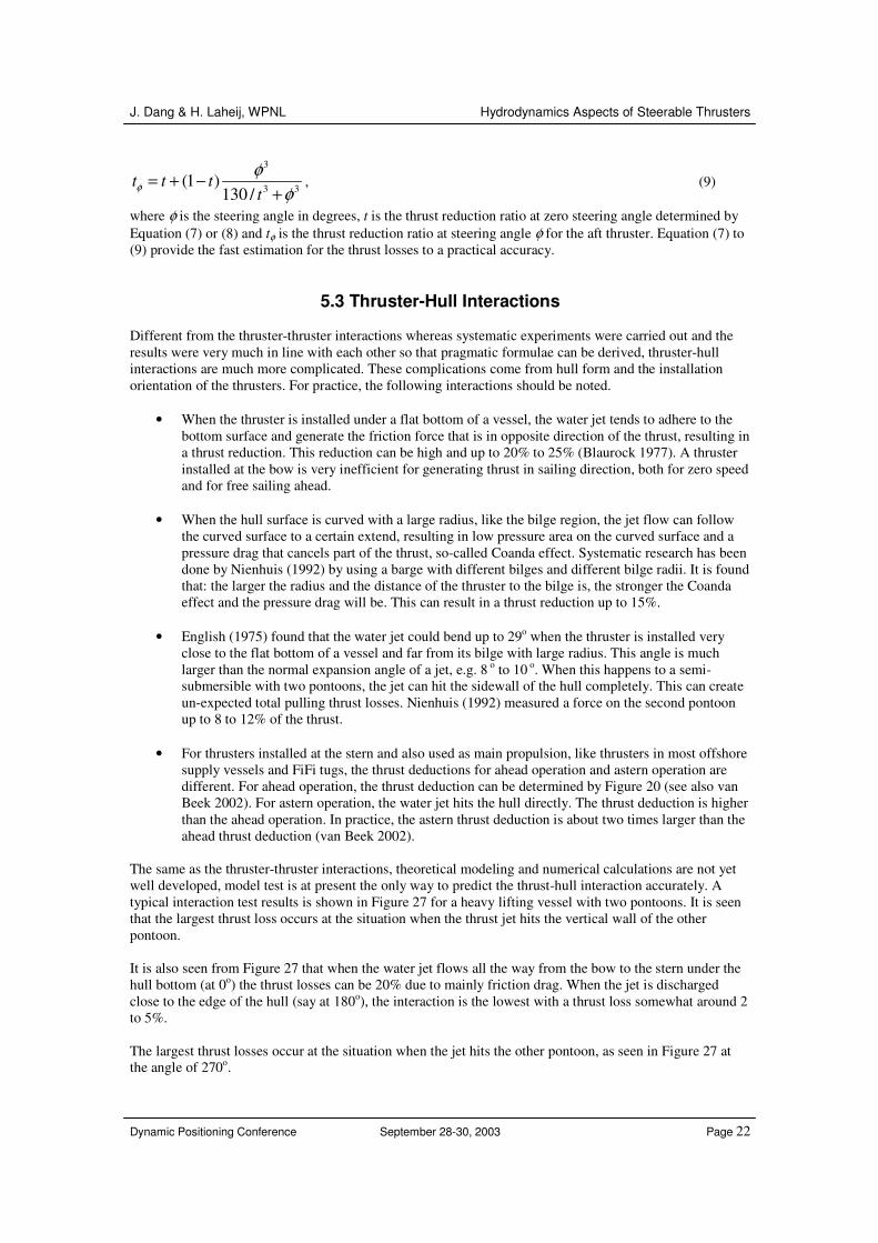
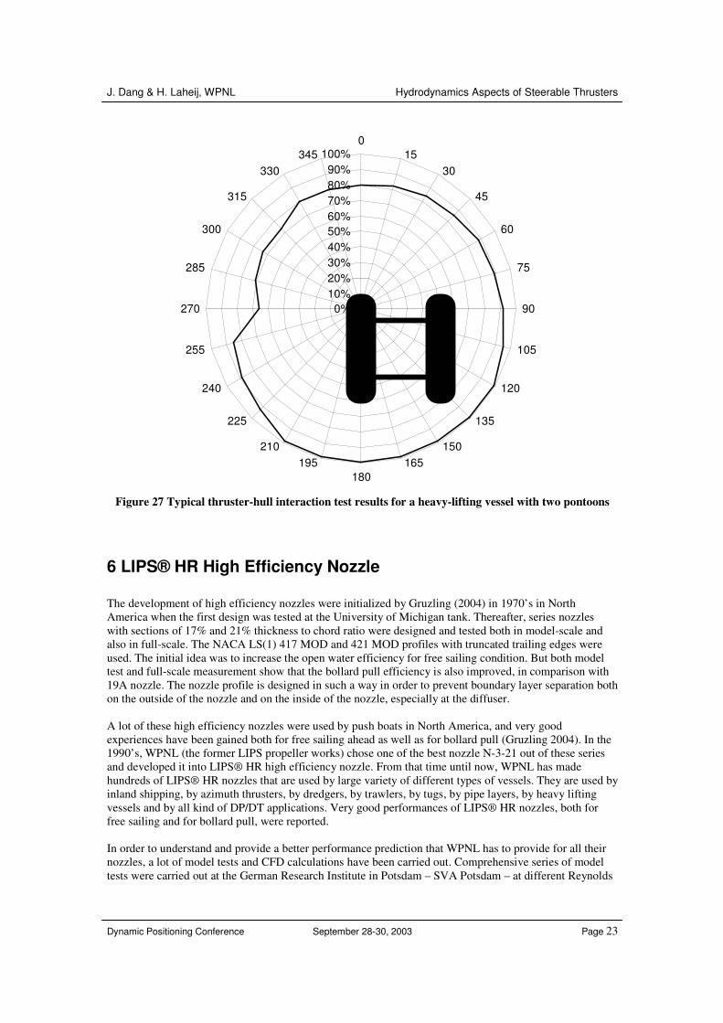
The same as the thruster-thruster interactions, theoretical modeling and numerical calculations are not yet well developed, model test is at present the only way to predict the thrust-hull interaction accurately. A typical interaction test results is shown in Figure 27 for a heavy lifting vessel with two pontoons. It is seen that the largest thrust loss occurs at the situation when the thrust jet hits the vertical wall of the other pontoon. It is also seen from Figure 27 that when the water jet flows all the way from the bow to the stern under the hull bottom (at 0o) the thrust losses can be 20% due to mainly friction drag. When the jet is discharged close to the edge of the hull (say at 180o), the interaction is the lowest with a thrust loss somewhat around 2 to 5%. The largest thrust losses occur at the situation when the jet hits the other pontoon, as seen in Figure 27 at the angle of 270o.
J. Dang & H. Laheij, WPNL Hydrodynamics Aspects of Steerable Thrusters
Dynamic Positioning Conference September 28-30, 2003 Page 23
0%10%20%30%40%50%60%70%80%90%
100%0
1530
45
60
75
90
105
120
135
150165
180195
210
225
240
255
270
285
300
315
330345
Figure 27 Typical thruster-hull interaction test results for a heavy-lifting vessel with two pontoons
6 LIPS® HR High Efficiency Nozzle The development of high efficiency nozzles were initialized by Gruzling (2004) in 1970’s in North America when the first design was tested at the University of Michigan tank. Thereafter, series nozzles with sections of 17% and 21% thickness to chord ratio were designed and tested both in model-scale and also in full-scale. The NACA LS(1) 417 MOD and 421 MOD profiles with truncated trailing edges were used. The initial idea was to increase the open water efficiency for free sailing condition. But both model test and full-scale measurement show that the bollard pull efficiency is also improved, in comparison with 19A nozzle. The nozzle profile is designed in such a way in order to prevent boundary layer separation both on the outside of the nozzle and on the inside of the nozzle, especially at the diffuser. A lot of these high efficiency nozzles were used by push boats in North America, and very good experiences have been gained both for free sailing ahead as well as for bollard pull (Gruzling 2004). In the 1990’s, WPNL (the former LIPS propeller works) chose one of the best nozzle N-3-21 out of these series and developed it into LIPS® HR high efficiency nozzle. From that time until now, WPNL has made hundreds of LIPS® HR nozzles that are used by large variety of different types of vessels. They are used by inland shipping, by azimuth thrusters, by dredgers, by trawlers, by tugs, by pipe layers, by heavy lifting vessels and by all kind of DP/DT applications. Very good performances of LIPS® HR nozzles, both for free sailing and for bollard pull, were reported. In order to understand and provide a better performance prediction that WPNL has to provide for all their nozzles, a lot of model tests and CFD calculations have been carried out. Comprehensive series of model tests were carried out at the German Research Institute in Potsdam – SVA Potsdam – at different Reynolds

J. Dang & H. Laheij, WPNL Hydrodynamics Aspects of Steerable Thrusters
Dynamic Positioning Conference September 28-30, 2003 Page 24
numbers. A comparing test of LIPS® HR nozzle to 19A nozzle shows a performance improvement of 8% to 10%. The reason is explained in the following. Figure 28 shows the flow visualization around the LIPS® nozzle profiles at different propeller thrust load conditions. It is seen that when the operation condition is close to the bollard pull condition (as shown in the first flow pattern in Figure 28), the stagnation point at the nose is moved to the middle on the outside surface of the nozzle. The water has to flow around the nose into the nozzle. The nose shape becomes then very important. On the other hand, the trailing edge flow separation is observed for all conditions, but they are different at different conditions.
Figure 28 Flow visualization studies on the LIPS® HR high efficiency nozzle
Figure 29 Calculated flow patterns at the trailing edge of 19A (two pictures on the left side) and Lips® HR high efficiency nozzle (two pictures on the right side) for both model and full-scale, at bollard condition
J. Dang & H. Laheij, WPNL Hydrodynamics Aspects of Steerable Thrusters
Dynamic Positioning Conference September 28-30, 2003 Page 25
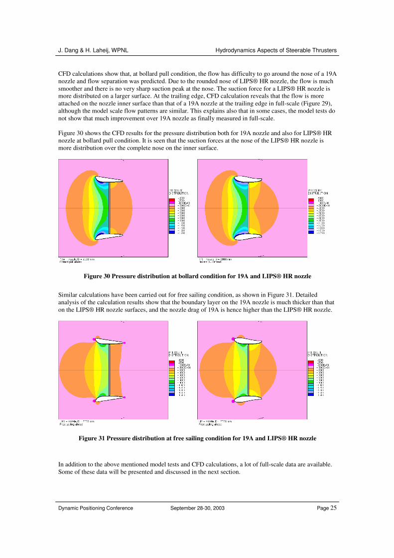
CFD calculations show that, at bollard pull condition, the flow has difficulty to go around the nose of a 19A nozzle and flow separation was predicted. Due to the rounded nose of LIPS® HR nozzle, the flow is much smoother and there is no very sharp suction peak at the nose. The suction force for a LIPS® HR nozzle is more distributed on a larger surface. At the trailing edge, CFD calculation reveals that the flow is more attached on the nozzle inner surface than that of a 19A nozzle at the trailing edge in full-scale (Figure 29), although the model scale flow patterns are similar. This explains also that in some cases, the model tests do not show that much improvement over 19A nozzle as finally measured in full-scale. Figure 30 shows the CFD results for the pressure distribution both for 19A nozzle and also for LIPS® HR nozzle at bollard pull condition. It is seen that the suction forces at the nose of the LIPS® HR nozzle is more distribution over the complete nose on the inner surface.
Figure 30 Pressure distribution at bollard condition for 19A and LIPS® HR nozzle
Similar calculations have been carried out for free sailing condition, as shown in Figure 31. Detailed analysis of the calculation results show that the boundary layer on the 19A nozzle is much thicker than that on the LIPS® HR nozzle surfaces, and the nozzle drag of 19A is hence higher than the LIPS® HR nozzle.
Figure 31 Pressure distribution at free sailing condition for 19A and LIPS® HR nozzle
In addition to the above mentioned model tests and CFD calculations, a lot of full-scale data are available. Some of these data will be presented and discussed in the next section.
J. Dang & H. Laheij, WPNL Hydrodynamics Aspects of Steerable Thrusters
Dynamic Positioning Conference September 28-30, 2003 Page 26
It is seen from the above discussion that the improvement of the LIPS® HR nozzle over 19A nozzle comes mainly from the improvement of the flow around the nozzle by using a more smoothed and carefully designed profile in stead of the simplified No. 19 nozzle (19A nozzle). Due to the large performance gain (up to 10%), thrusters with LIPS® HR high efficiency nozzle become very important for improving the performance of dynamic positioning and dynamic tracking in the offshore industry.
7 Application of Thrusters for Dynamic Positioning/Dynamic Tracking In this section a few examples of steerable thruster installations in offshore applications are given. Discussions are given to both DP/DT performance and transit mode. Some full-scale propeller performance data are provided.
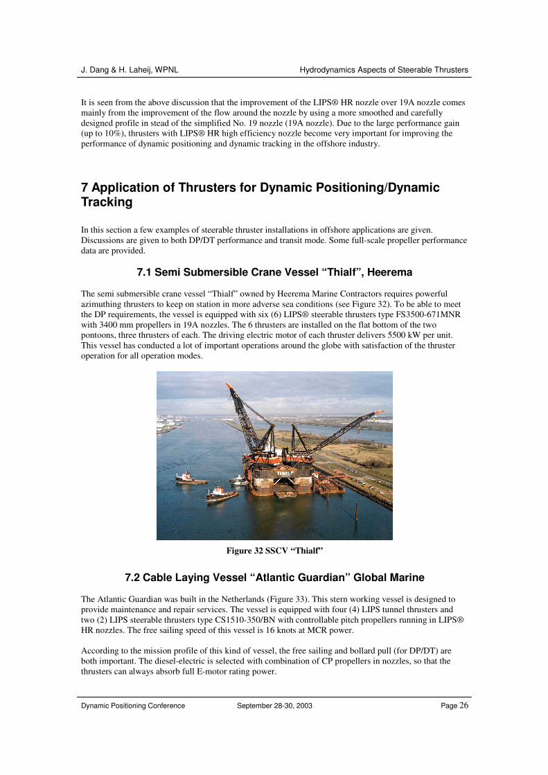
7.1 Semi Submersible Crane Vessel “Thialf”, Heerema The semi submersible crane vessel “Thialf” owned by Heerema Marine Contractors requires powerful azimuthing thrusters to keep on station in more adverse sea conditions (see Figure 32). To be able to meet the DP requirements, the vessel is equipped with six (6) LIPS® steerable thrusters type FS3500-671MNR with 3400 mm propellers in 19A nozzles. The 6 thrusters are installed on the flat bottom of the two pontoons, three thrusters of each. The driving electric motor of each thruster delivers 5500 kW per unit. This vessel has conducted a lot of important operations around the globe with satisfaction of the thruster operation for all operation modes.
Figure 32 SSCV “Thialf”
7.2 Cable Laying Vessel “Atlantic Guardian” Global Marine
The Atlantic Guardian was built in the Netherlands (Figure 33). This stern working vessel is designed to provide maintenance and repair services. The vessel is equipped with four (4) LIPS tunnel thrusters and two (2) LIPS steerable thrusters type CS1510-350/BN with controllable pitch propellers running in LIPS® HR nozzles. The free sailing speed of this vessel is 16 knots at MCR power. According to the mission profile of this kind of vessel, the free sailing and bollard pull (for DP/DT) are both important. The diesel-electric is selected with combination of CP propellers in nozzles, so that the thrusters can always absorb full E-motor rating power.
J. Dang & H. Laheij, WPNL Hydrodynamics Aspects of Steerable Thrusters
Dynamic Positioning Conference September 28-30, 2003 Page 27
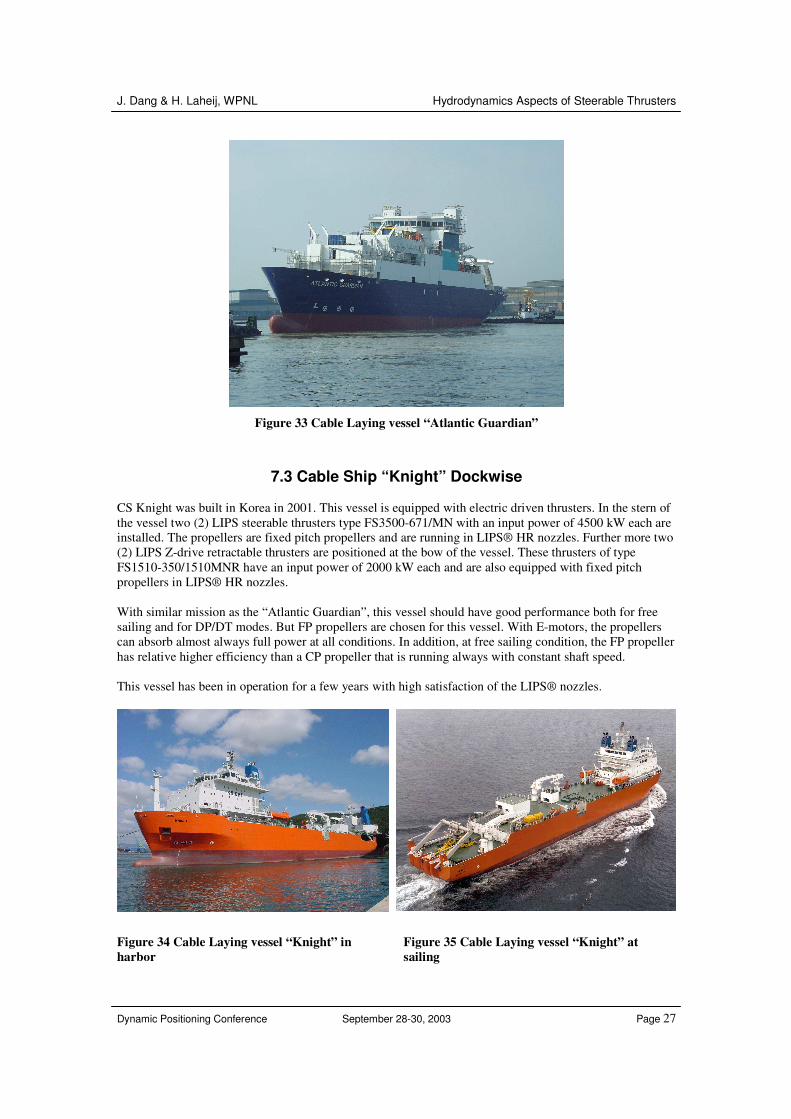
Figure 33 Cable Laying vessel “Atlantic Guardian”
7.3 Cable Ship “Knight” Dockwise CS Knight was built in Korea in 2001. This vessel is equipped with electric driven thrusters. In the stern of the vessel two (2) LIPS steerable thrusters type FS3500-671/MN with an input power of 4500 kW each are installed. The propellers are fixed pitch propellers and are running in LIPS® HR nozzles. Further more two (2) LIPS Z-drive retractable thrusters are positioned at the bow of the vessel. These thrusters of type FS1510-350/1510MNR have an input power of 2000 kW each and are also equipped with fixed pitch propellers in LIPS® HR nozzles. With similar mission as the “Atlantic Guardian”, this vessel should have good performance both for free sailing and for DP/DT modes. But FP propellers are chosen for this vessel. With E-motors, the propellers can absorb almost always full power at all conditions. In addition, at free sailing condition, the FP propeller has relative higher efficiency than a CP propeller that is running always with constant shaft speed. This vessel has been in operation for a few years with high satisfaction of the LIPS® nozzles.
Figure 34 Cable Laying vessel “Knight” in harbor
Figure 35 Cable Laying vessel “Knight” at sailing
J. Dang & H. Laheij, WPNL Hydrodynamics Aspects of Steerable Thrusters
Dynamic Positioning Conference September 28-30, 2003 Page 28
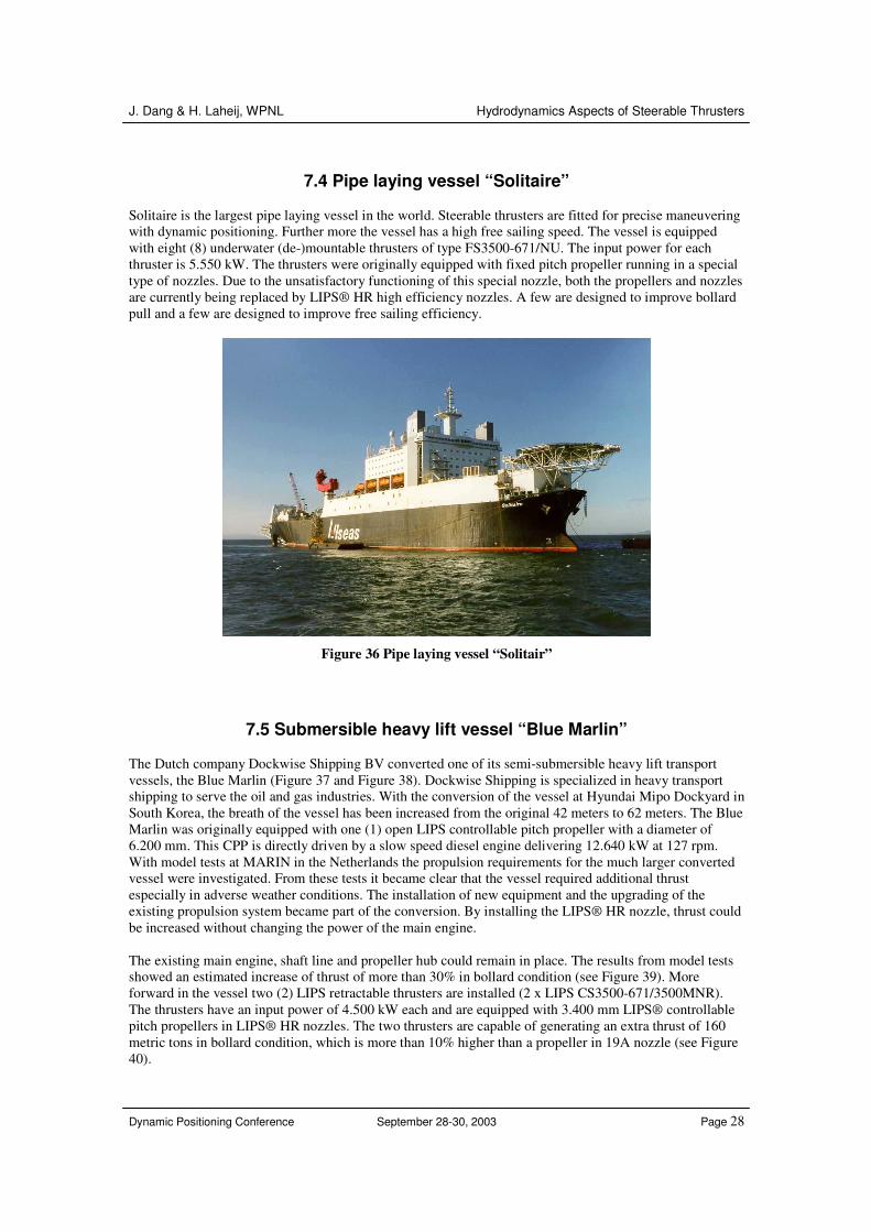
7.4 Pipe laying vessel “Solitaire”
Solitaire is the largest pipe laying vessel in the world. Steerable thrusters are fitted for precise maneuvering with dynamic positioning. Further more the vessel has a high free sailing speed. The vessel is equipped with eight (8) underwater (de-)mountable thrusters of type FS3500-671/NU. The input power for each thruster is 5.550 kW. The thrusters were originally equipped with fixed pitch propeller running in a special type of nozzles. Due to the unsatisfactory functioning of this special nozzle, both the propellers and nozzles are currently being replaced by LIPS® HR high efficiency nozzles. A few are designed to improve bollard pull and a few are designed to improve free sailing efficiency.
Figure 36 Pipe laying vessel “Solitair”
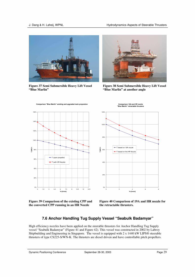
7.5 Submersible heavy lift vessel “Blue Marlin” The Dutch company Dockwise Shipping BV converted one of its semi-submersible heavy lift transport vessels, the Blue Marlin (Figure 37 and Figure 38). Dockwise Shipping is specialized in heavy transport shipping to serve the oil and gas industries. With the conversion of the vessel at Hyundai Mipo Dockyard in South Korea, the breath of the vessel has been increased from the original 42 meters to 62 meters. The Blue Marlin was originally equipped with one (1) open LIPS controllable pitch propeller with a diameter of 6.200 mm. This CPP is directly driven by a slow speed diesel engine delivering 12.640 kW at 127 rpm. With model tests at MARIN in the Netherlands the propulsion requirements for the much larger converted vessel were investigated. From these tests it became clear that the vessel required additional thrust especially in adverse weather conditions. The installation of new equipment and the upgrading of the existing propulsion system became part of the conversion. By installing the LIPS® HR nozzle, thrust could be increased without changing the power of the main engine. The existing main engine, shaft line and propeller hub could remain in place. The results from model tests showed an estimated increase of thrust of more than 30% in bollard condition (see Figure 39). More forward in the vessel two (2) LIPS retractable thrusters are installed (2 x LIPS CS3500-671/3500MNR). The thrusters have an input power of 4.500 kW each and are equipped with 3.400 mm LIPS® controllable pitch propellers in LIPS® HR nozzles. The two thrusters are capable of generating an extra thrust of 160 metric tons in bollard condition, which is more than 10% higher than a propeller in 19A nozzle (see Figure 40).
J. Dang & H. Laheij, WPNL Hydrodynamics Aspects of Steerable Thrusters
Dynamic Positioning Conference September 28-30, 2003 Page 29
Figure 37 Semi Submersible Heavy Lift Vessel “Blue Marlin”
Figure 38 Semi Submersible Heavy Lift Vessel “Blue Marlin” at another angle
Comparison "Blue Marlin" existing and upgraded main propulsion
0%
20%
40%
60%
80%
100%
120%
140%
160%
0 1.5 3 4.5 6 7.5 9 10.5 12 13.5
Vs [knots]
T [k
N] %
T (open propeller)
T (with HR Nozzle)
Comparison 19A and HR nozzle "Blue Marlin" retractable thrusters
0%
20%
40%
60%
80%
100%
120%
0 2 4 6 8
Vs [knots]
T [k
N] %
T based on 19A nozzle
T based on the HR Nozzle
Figure 39 Comparison of the existing CPP and the converted CPP running in an HR Nozzle
Figure 40 Comparison of 19A and HR nozzle for the retractable thrusters.
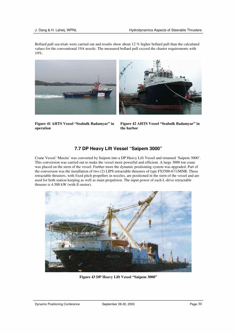
7.6 Anchor Handling Tug Supply Vessel “Seabulk Badamyar” High efficiency nozzles have been applied on the steerable thrusters for Anchor Handling Tug Supply vessel “Seabulk Badamyar” (Figure 41 and Figure 42). This vessel was constructed in 2002 by Labroy Shipbuilding and Engineering in Singapore. The vessel is equipped with 2 x 1440 kW LIPS® steerable thrusters of type CS225-S/WN-K. The thrusters are diesel driven and have controllable pitch propellers.
J. Dang & H. Laheij, WPNL Hydrodynamics Aspects of Steerable Thrusters
Dynamic Positioning Conference September 28-30, 2003 Page 30
Bollard pull sea-trials were carried out and results show about 12 % higher bollard pull than the calculated values for the conventional 19A nozzle. The measured bollard pull exceed the charter requirements with 10%.
Figure 41 AHTS Vessel “Seabulk Badamyar” in operation
Figure 42 AHTS Vessel “Seabulk Badamyar” in the harbor
7.7 DP Heavy Lift Vessel “Saipem 3000” Crane Vessel ‘Maxita’ was converted by Saipem into a DP Heavy Lift Vessel and renamed ‘Saipem 3000’. This conversion was carried out to make the vessel more powerful and efficient. A large 3000 ton crane was placed on the stern of the vessel. Further more the dynamic positioning system was upgraded. Part of the conversion was the installation of two (2) LIPS retractable thrusters of type FS3500-671/MNR. These retractable thrusters, with fixed pitch propellers in nozzles, are positioned in the stern of the vessel and are used for both station keeping as well as main propulsion. The input power of each L-drive retractable thruster is 4.500 kW (with E-motor).
Figure 43 DP Heavy Lift Vessel “Saipem 3000”
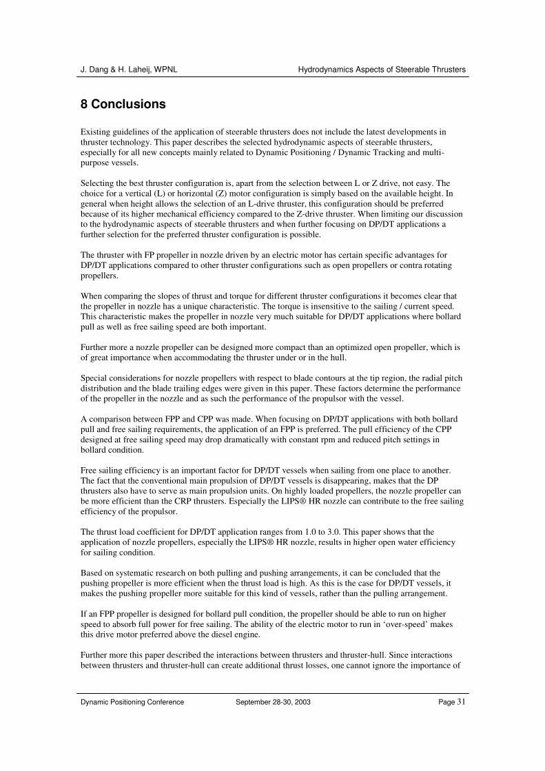
J. Dang & H. Laheij, WPNL Hydrodynamics Aspects of Steerable Thrusters
Dynamic Positioning Conference September 28-30, 2003 Page 31
8 Conclusions Existing guidelines of the application of steerable thrusters does not include the latest developments in thruster technology. This paper describes the selected hydrodynamic aspects of steerable thrusters, especially for all new concepts mainly related to Dynamic Positioning / Dynamic Tracking and multi-purpose vessels. Selecting the best thruster configuration is, apart from the selection between L or Z drive, not easy. The choice for a vertical (L) or horizontal (Z) motor configuration is simply based on the available height. In general when height allows the selection of an L-drive thruster, this configuration should be preferred because of its higher mechanical efficiency compared to the Z-drive thruster. When limiting our discussion to the hydrodynamic aspects of steerable thrusters and when further focusing on DP/DT applications a further selection for the preferred thruster configuration is possible. The thruster with FP propeller in nozzle driven by an electric motor has certain specific advantages for DP/DT applications compared to other thruster configurations such as open propellers or contra rotating propellers. When comparing the slopes of thrust and torque for different thruster configurations it becomes clear that the propeller in nozzle has a unique characteristic. The torque is insensitive to the sailing / current speed. This characteristic makes the propeller in nozzle very much suitable for DP/DT applications where bollard pull as well as free sailing speed are both important. Further more a nozzle propeller can be designed more compact than an optimized open propeller, which is of great importance when accommodating the thruster under or in the hull. Special considerations for nozzle propellers with respect to blade contours at the tip region, the radial pitch distribution and the blade trailing edges were given in this paper. These factors determine the performance of the propeller in the nozzle and as such the performance of the propulsor with the vessel. A comparison between FPP and CPP was made. When focusing on DP/DT applications with both bollard pull and free sailing requirements, the application of an FPP is preferred. The pull efficiency of the CPP designed at free sailing speed may drop dramatically with constant rpm and reduced pitch settings in bollard condition. Free sailing efficiency is an important factor for DP/DT vessels when sailing from one place to another. The fact that the conventional main propulsion of DP/DT vessels is disappearing, makes that the DP thrusters also have to serve as main propulsion units. On highly loaded propellers, the nozzle propeller can be more efficient than the CRP thrusters. Especially the LIPS® HR nozzle can contribute to the free sailing efficiency of the propulsor. The thrust load coefficient for DP/DT application ranges from 1.0 to 3.0. This paper shows that the application of nozzle propellers, especially the LIPS® HR nozzle, results in higher open water efficiency for sailing condition. Based on systematic research on both pulling and pushing arrangements, it can be concluded that the pushing propeller is more efficient when the thrust load is high. As this is the case for DP/DT vessels, it makes the pushing propeller more suitable for this kind of vessels, rather than the pulling arrangement. If an FPP propeller is designed for bollard pull condition, the propeller should be able to run on higher speed to absorb full power for free sailing. The ability of the electric motor to run in ‘over-speed’ makes this drive motor preferred above the diesel engine. Further more this paper described the interactions between thrusters and thruster-hull. Since interactions between thrusters and thruster-hull can create additional thrust losses, one cannot ignore the importance of
J. Dang & H. Laheij, WPNL Hydrodynamics Aspects of Steerable Thrusters
Dynamic Positioning Conference September 28-30, 2003 Page 32
thruster-thruster and thruster-hull interactions. Since DP thrusters are also used as main propulsors, knowledge of these losses become even more important. This paper gave a guideline in those losses and empirical formulae that can provide estimation up to engineer accuracy. The development of the LIPS® HR nozzle can increase the efficiency of large thruster installations. Although first developed for smaller applications, the LIPS® HR nozzle can be effectively applied and proved to be effective in DP/DT applications. The application of the high efficiency nozzle is by far the most reliable, robust and simple method to improve the performance of the propulsor.
Acknowledgement Ir. N. W. H. Bulten made all of the CFD calculations for both 19A and LIPS® HR high efficiency nozzles with clear and high quality figures, which provided invaluable insight into the flow and the flow differences around those nozzles. Ir. J. Th. Ligtelijn has read the draft of this paper and provided very valuable comments that were taken into the revision of this paper. Thanks should also be extended to the Azimuth Thruster Product Group in Wärtsilä Propulsion Netherlands BV (WPNL), who encouraged and supported to finish this paper and to publish the invaluable full-scale data.
References Beek T. van, Carbaat-Visser J., Ju J., Werf Haijo van der and Wesselink A. (2002) ‘Selection of Tug Power System,’ Proceedings of 17th International Tug & Salvage Convention, pp131-143. Blaurock J. (1977) ‘Gegenseitige Beeinflussung von zwei unter einem Schimmkörper arbeitenden Schottel-Rudderproepllern,’ HSVA – Bericht PS 2/77, Juni. Brown N. A. & Norton J. A. (1975) ‘Thruster Design for Acoustic Positioning Systems,’ Journal of Marine Technology, pp 122-137, April. Chu C., Chan Z. L., She Y. S. & Yuan V. Z. (1979) ‘The 3-Bladed JD-CPP Series,’ Proceedings of the 4th LIPS Propeller Symposium, pp 53-79, October, Drunen, The Netherlands. Deter D. (1997) ‘Principal Aspects of Thruster Selection,’ Proceedings of Dynamic Positioning Conference, Marine Technology Society, 21-22 October 1997. English J. W. (1975) ‘Propeller/hull interaction,’ Proceedings of the 14th International Towing Tank Conference, pp294-306. Gruzling J. (2004) ‘The Development and Application of High Efficiency Nozzles and Rudders,’ Proceedings of SNAME 2004, September, Washington D. C. Heinke C. & Heinke H-J. (2003) ‘Investigations about the Use of Podded Drives for Fast Ships’ proceedings of the 7th International Conference on Fast Sea Transportation 2003, pp 41-48, Ischia, Italy, October, 2003. Kuiper G. (1992) ‘The Wageningen Propeller Series,’ MARIN publication 92-001, Wageningen, the Netherlands, May 1992. Lehn E. (1980) ‘Thruster Interaction Effect,’ NSFI Report-102.80, The Ship Research Institute of Norway. Manen J. D. van (1962) ‘Effect of Radial Load Distribution on the Performance of Shrouded Propellers,’ International Shipbuilding Progress, Vol. 9, No. 93, May 1962.
J. Dang & H. Laheij, WPNL Hydrodynamics Aspects of Steerable Thrusters
Dynamic Positioning Conference September 28-30, 2003 Page 33
Moberg S. & Hellström S. A. (1983) ‘Dynamic Positioning of a Four-Column Semi-Submersible. Model Tests of Interaction Forces and A Philosophy about Optimum Strategy when Operating the thrusters,’ Proceedings of the Second International Symposium on Ocean Engineering and Ship Handling, pp443-480, March 1-3, Gothenburg, Sweden. Nienhuis U. (1992) ‘Analysis of Thruster Effectivity for Dynamic Positioning and Low Speed Manoeuvring,’ Dissertation of Technical University Delft. Oosterveld M. W. C. & Oortmerssen G. van (1972) ‘Thruster Systems for Improving the Manueverability and Position-keeping Capacity of Floating Objects,’ Proceedings of Fourth Annual Offshore Technology Conference in Houston, OTC-1625, May 1-3, 1972. Praefke E., Richards J. & Engelskirchen J. (2001) ‘Counter Rotating Propellers without Complex Shafting for a Fast Monohull Ferry,’ The 6th International Conference on Fast Sea Transportation, Southampton, UK, September 4-6. Rijsbergen M. X. van & Terwisga T. J. C. van (2000) ‘On the Maximum Thrust Density of Propellers,’ NCT’50 International Conference on Propeller Cavitation, Newcastle, 3-5 April, 2000. Schneiders C. & Hageman A. S. (1977) ‘Manoeuvring tug/anchor-handeling/supply vessels’, International Tug & Salvage Conference 1977. Terwisga T. van, Quadvlieg F. & Valkhof H. (2001) ‘Steerable Propulsion Units: Hydrodynamic Issues and Design Consequences,’ 80th Anniversary of Schottel GmbH & Co., 11 August 2001. Toxopeus S & Loeff G. (2002) ‘Manoeuvring Aspects of Fast Ships with Pods,’ Proceeding of the 3rd International EuroConference on High-Performance Marine Vehicles HIPER’02, Bergen, 14-17 September, pp392-406.