r'-:/ Preloaded Joint Analysis Methodology for Space Flight Systems
DYNAMIC PERFORMANCE OF OFFSET-PRELOADED TWO PAD FOIL BEARINGS
by
SHRIKANT ASHOK YADAV
Presented to the Faculty of the Graduate School of
The University of Texas at Arlington in Partial Fulfillment
of the Requirements
for the Degree of
MASTER OF SCIENCE IN MECHANICAL ENGINEERING
THE UNIVERSITY OF TEXAS AT ARLINGTON
DECEMBER 2012
ii
Copyright © by Shrikant Ashok Yadav 2012
All Rights Reserved
iii
Acknowledgements
I sincerely thank my committee chair, Dr. Daejong Kim for his guidance, and
support throughout the course of research. I would also like to thank Dr. Kent Lawrence
and Dr. Bo Wang for serving as committee member.
I would like to express my gratitude to Kermit Beird and Sam Williams from
machine shop for helping me at each stage in fabrication and assembly of test setup. I
would like to thank my colleagues and friends in Microturbomachinary and Energy
Systems Lab for their help and support. I would also like to acknowledge the financial
support provided by Dr. Kim and sponsor.
And last but not the least, I would thank my family and friends for their love and
support for all these years.
December 14, 2012
iv
Abstract
DYNAMIC PERFORMANCE OF OFFSET-PRELOADED TWO PAD FOIL BEARINGS
Shrikant Ashok Yadav, MS
The University of Texas at Arlington, 2012
Supervising Professor: Daejong Kim
Commercial application of the air foil bearing (AFB) in microturbomachinary have
been acknowledged. Absence of external pressurizing and lubricating system makes
them light and compact. Simple construction, low friction drag and reliability at high speed
operations are few more advantages of the AFBs. With all these advantages AFB proves
to be the suitable option for oil-free small turbomachinery which includes micro gas
turbines with shaft power less than 1000hp. Micro gas turbine generators are typically
two shaft configuration with power generation capacity less than 500KW. Although many
micro gas turbines with AFBs have been developed, due to the proprietary nature of their
bearings, no specific information about shape and configuration of the bearings is
available.
This work presents the dynamic performance of offset-preloaded two pad foil
bearings, which is designed and developed for the sponsor project. The scope of the
sponsor project was to design journal bearings and thrust bearings for 12KW gas turbine
operating at rated engine speed of 138,000 rpm. At this high speed operation, rotor
stability is an important issue. From the previous research, it is known that bearings with
multi pad configurations are more stable than single pad configuration. Hence, an offset-
preloaded two pad bearing configuration was selected for further developed for the
sponsor project. Dynamic performance of the bearing was investigated by calculating
v
frequency-dependent stiffness coefficients and damping coefficients. And the stability
analysis for cylindrical mode was performed by determining modal impedances; where
positive modal damping over all frequency is interpreted as a stable rotor-bearing system.
A code developed by Dr. Kim, which implements the perturbation method for evaluating
the frequency-dependent force coefficients is used for this purpose. The geometric and
operational parameters are the input for this code. The bump stiffness and structural
damping loss factor of the bump foil was evaluated from load-deflection tests, which were
used as input parameter to the simulation.
In addition to original designed orientation, dynamic performance of the bearing
was evaluated for various clocked orientations like +/- 90o and +/- 45o. Results indicated
that at all the clocked orientations, the bearing is stable. Hence, unlike single pad circular
foil bearings, this offset-preloaded two pad bearing is stable at any clocked orientation.
This novel feature of the offset-preloaded two pad bearing makes it possible to install the
bearing in any orientation.
vi
Table of Contents
Acknowledgements ............................................................................................................. iii
Abstract .............................................................................................................................. iv
List of Illustrations ............................................................................................................. viii
List of Tables ....................................................................................................................... x
Nomenclature ..................................................................................................................... xi
Chapter 1 Introduction .................................................................................................... 1
1.1 Air Foil Journal Bearing ..................................................................................... 1
1.1.1 Principle of Operation: ................................................................................... 2
1.2 Air Foil Thrust Bearing ....................................................................................... 3
1.2.1 Principle of Operation: ................................................................................... 3
1.3 Multi-pad Air Foil Bearing .................................................................................. 4
1.4 Micro Gas Turbine ............................................................................................. 5
1.5 Background of Thesis ........................................................................................ 6
Chapter 2 Literature Review .......................................................................................... 8
2.1 Research Objective ......................................................................................... 12
Chapter 3 Configuration and Manufacturing of Foil Bearing ........................................ 14
3.1 Definition of Clearance .................................................................................... 14
3.2 Clearance and Offset Preload in AFB ............................................................. 15
3.3 Manufacturing Process of Foil Bearing ........................................................... 18
3.3.1 Bump Foil .................................................................................................... 18
3.3.2 Top Foil ........................................................................................................ 19
3.3.3 Bearing Sleeve. ........................................................................................... 21
Chapter 4 Gas Film Lubrication Theory ....................................................................... 23
4.1 Reynolds Equation .......................................................................................... 24
vii
4.2 Stiffness and Damping Coefficient Equation ................................................... 24
4.3 Modal Impedance ............................................................................................ 28
Chapter 5 Results and Discussion ............................................................................... 30
5.1 Structural Characterization .............................................................................. 30
5.2 Test Setup ....................................................................................................... 32
5.3 Test Results ..................................................................................................... 35
5.4 Clearance and Preload Selection .................................................................... 37
5.5 Effect of Bearing Orientation and Loss Factor ................................................ 42
Chapter 6 Conclusion and Future Work ....................................................................... 51
6.1 Conclusion ....................................................................................................... 51
6.2 Future Work ..................................................................................................... 52
Appendix A Data Acquisition Using Lab View .................................................................. 53
Bibliography ...................................................................................................................... 56
Biographical Information ................................................................................................... 58
viii
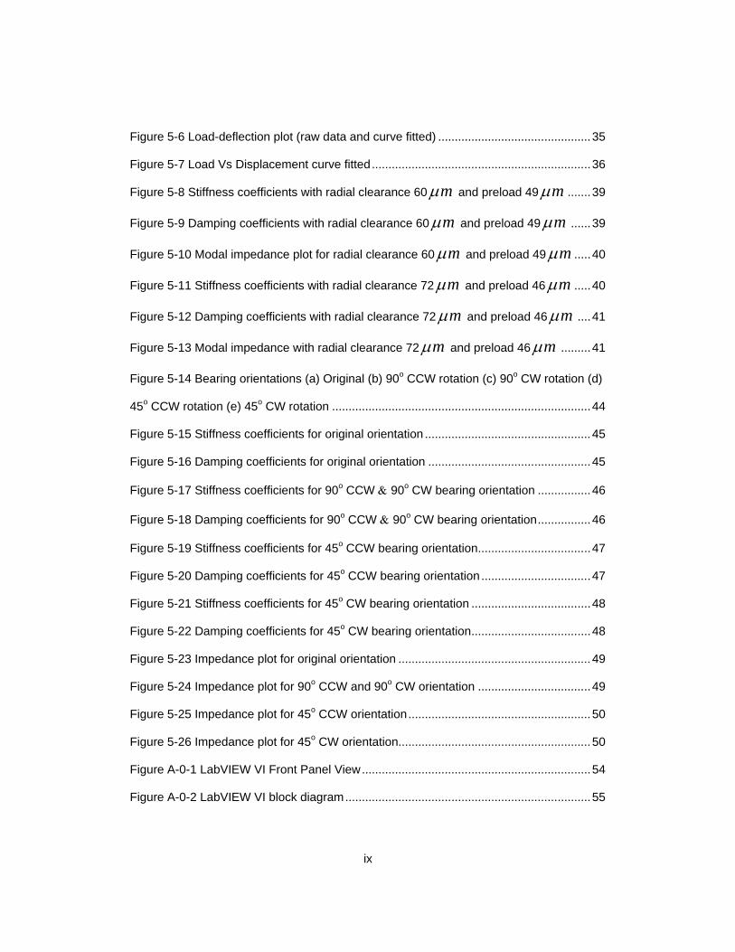
List of Illustrations
Figure 1-1 Schematic of Air Foil Journal Bearing ............................................................... 2
Figure 1-2 Air Foil Thrust Bearing, image from [2] .............................................................. 3
Figure 1-3 Multi-pad foil bearing, image from [1] ................................................................ 4
Figure 1-4 Three pad foil bearing with non-uniform bearing clearance, image from [3] ..... 5
Figure
1-5 Rotor configuration for typical single stage micro gas turbine, image from
Capstone Turbine Corporation ............................................................................................ 6
Figure 3-1 Exaggerated Loose Assembly of AFB without Rotor ...................................... 14
Figure 3-2 Pad angle and offset angle in offset-preloaded two pad bearing [15] ............. 16
Figure 3-3 Hydrodynamic preload in offset-preloaded two pad bearing [15] .................... 16
Figure
3-4 Form-Feed-Hold-Form (a) Forming of bumps (b) Formed bumps are held in
holding region of jig ........................................................................................................... 19
Figure 3-5 Bump foils ........................................................................................................ 19
Figure 3-6 Top foil forming jig 1 ........................................................................................ 20
Figure 3-7 Top foil lip forming jig 2 .................................................................................... 20
Figure 3-8 Top Foil ............................................................................................................ 21
Figure 3-9 Top assembly in Bearing sleeve...................................................................... 21
Figure 3-10 Bearing Sleeve .............................................................................................. 22
Figure 4-1 Journal bearing in normal operating condition ................................................ 23
Figure 4-2 Cross section of eccentric journal bearing ...................................................... 28
Figure 5-1 Schematic of load-deflection test without clearance ....................................... 30
Figure 5-2 Load-deflection test setup top view ................................................................. 32
Figure 5-3 Load-deflection test setup side view ............................................................... 33
Figure 5-4 Proximity curve calibration plot ........................................................................ 34
Figure 5-5 Load cell calibration plot .................................................................................. 34
ix
Figure 5-6 Load-deflection plot (raw data and curve fitted) .............................................. 35
Figure 5-7 Load Vs Displacement curve fitted .................................................................. 36
Figure mµ 5-8 Stiffness coefficients with radial clearance 60 and preload 49 mµ ....... 39
Figure mµ 5-9 Damping coefficients with radial clearance 60 and preload 49 mµ ...... 39
Figure mµ 5-10 Modal impedance plot for radial clearance 60 and preload 49 mµ ..... 40
Figure mµ 5-11 Stiffness coefficients with radial clearance 72 and preload 46 mµ ..... 40
Figure mµ 5-12 Damping coefficients with radial clearance 72 and preload 46 mµ .... 41
Figure mµ 5-13 Modal impedance with radial clearance 72 and preload 46 mµ ......... 41
Figure
5-14 Bearing orientations (a) Original (b) 90o CCW rotation (c) 90o CW rotation (d)
45o CCW rotation (e) 45o CW rotation .............................................................................. 44
Figure 5-15 Stiffness coefficients for original orientation .................................................. 45
Figure 5-16 Damping coefficients for original orientation ................................................. 45
Figure 5-17 Stiffness coefficients for 90o CCW & 90o CW bearing orientation ................ 46
Figure 5-18 Damping coefficients for 90o CCW & 90o CW bearing orientation ................ 46
Figure 5-19 Stiffness coefficients for 45o CCW bearing orientation .................................. 47
Figure 5-20 Damping coefficients for 45o CCW bearing orientation ................................. 47
Figure 5-21 Stiffness coefficients for 45o CW bearing orientation .................................... 48
Figure 5-22 Damping coefficients for 45o CW bearing orientation .................................... 48
Figure 5-23 Impedance plot for original orientation .......................................................... 49
Figure 5-24 Impedance plot for 90o CCW and 90o CW orientation .................................. 49
Figure 5-25 Impedance plot for 45o CCW orientation ....................................................... 50
Figure 5-26 Impedance plot for 45o CW orientation.......................................................... 50
Figure A-0-1 LabVIEW VI Front Panel View ..................................................................... 54
Figure A-0-2 LabVIEW VI block diagram .......................................................................... 55
x
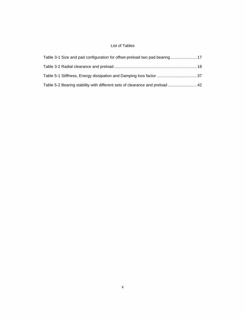
List of Tables
Table 3-1 Size and pad configuration for offset-preload two pad bearing ........................ 17
Table 3-2 Radial clearance and preload ........................................................................... 18
Table 5-1 Stiffness, Energy dissipation and Damping loss factor .................................... 37
Table 5-2 Bearing stability with different sets of clearance and preload .......................... 42
xi
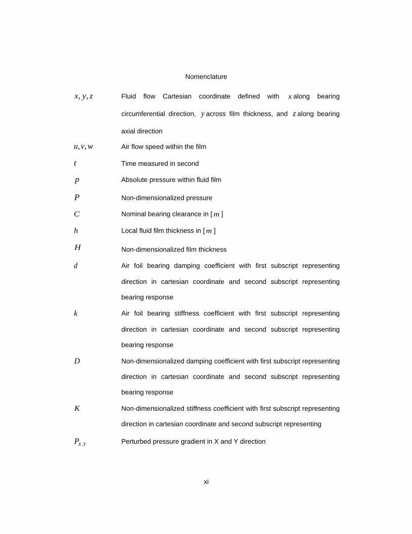
Nomenclature
, ,x y z Fluid flow Cartesian coordinate defined with x along bearing
circumferential direction, y across film thickness, and z along bearing
axial direction
, ,u v w Air flow speed within the film
t Time measured in second
p Absolute pressure within fluid film
P Non-dimensionalized pressure
C Nominal bearing clearance in [ m ]
h Local fluid film thickness in [ m ]
H Non-dimensionalized film thickness
d Air foil bearing damping coefficient with first subscript representing
direction in cartesian coordinate and second subscript representing
bearing response
k Air foil bearing stiffness coefficient with first subscript representing
direction in cartesian coordinate and second subscript representing
bearing response
D Non-dimensionalized damping coefficient with first subscript representing
direction in cartesian coordinate and second subscript representing
bearing response
K Non-dimensionalized stiffness coefficient with first subscript representing
direction in cartesian coordinate and second subscript representing
,X YP Perturbed pressure gradient in X and Y direction
xii
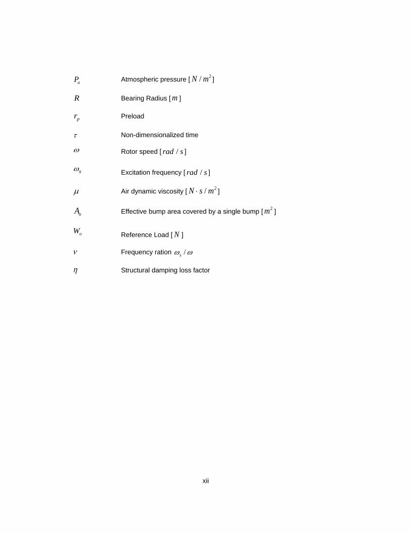
aP Atmospheric pressure [ 2/N m ]
R Bearing Radius [ m ]
pr Preload
τ Non-dimensionalized time
ω Rotor speed [ /rad s ]
sω Excitation frequency [ /rad s ]
µ Air dynamic viscosity [ 2/N s m⋅ ]
oA Effective bump area covered by a single bump [ 2m ]
oW Reference Load [ N ]
ν Frequency ration /sω ω
η Structural damping loss factor
1
Chapter 1
Introduction
Air foil bearings (AFB) have gained significant attention in recent years because
of various advantages. Air being used as a lubricant, eliminates the need for a bulky
lubrication system, which is needed for an oil-lubricated bearing. The absence of external
pressurizing or lubrication system makes an overall system compact and light weight.
Cleaner environment is an additional advantage of using the air as the lubricant. The oil
lubricated bearing generally suffers a thermal degradation at a high temperature while the
oil becomes too viscous at low temperature. On the contrary, the air foil bearing can
operate at wide range of temperature ranging from high temperatures (> 500oC) to
cryogenic temperatures [1]. Air foil bearings gained wide acceptance in industry these
days, which includes auxiliary power unit, air cycle machine, turbo alternator and small
turbomachinery.
1.1 Air Foil Journal Bearing
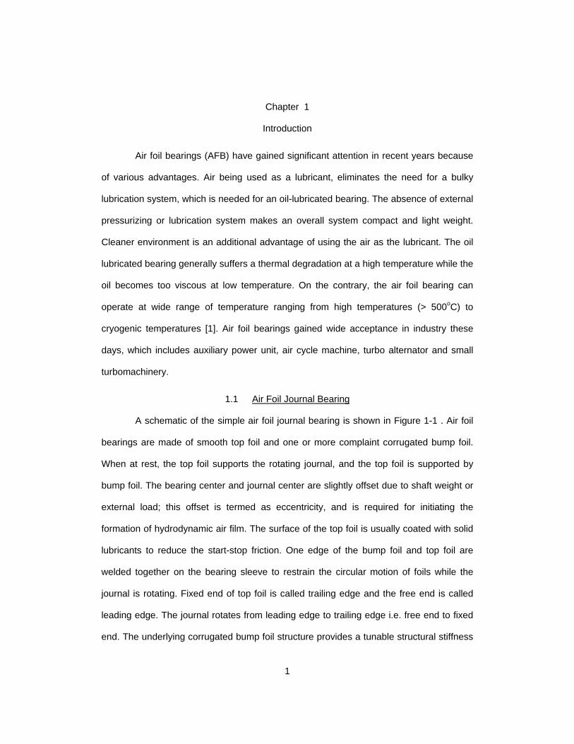
A schematic of the simple air foil journal bearing is shown in Figure 1-1 . Air foil
bearings are made of smooth top foil and one or more complaint corrugated bump foil.
When at rest, the top foil supports the rotating journal, and the top foil is supported by
bump foil. The bearing center and journal center are slightly offset due to shaft weight or
external load; this offset is termed as eccentricity, and is required for initiating the
formation of hydrodynamic air film. The surface of the top foil is usually coated with solid
lubricants to reduce the start-stop friction. One edge of the bump foil and top foil are
welded together on the bearing sleeve to restrain the circular motion of foils while the
journal is rotating. Fixed end of top foil is called trailing edge and the free end is called
leading edge. The journal rotates from leading edge to trailing edge i.e. free end to fixed
end. The underlying corrugated bump foil structure provides a tunable structural stiffness
2
and coulomb type damping is generated by relative motion between the bump foils and
top foils. The structural stiffness of the bump foil is typically controlled by bump geometry
and material. Typically super alloy like nickel chromium alloy trademarked as Inconel is
used for bump foil and top foil.
Figure 1-1 Schematic of Air Foil Journal Bearing
1.1.1 Principle of Operation:
Initial radial clearance creates the wedge-shaped void when the journal is at rest.
Hydrodynamic pressure starts building up in this void wedge, when the journal starts
rotating. Gradually the contact area between journal and top foil is reduced, until the
journal reaches lift off speed. Once the lift off speed is reached, journal is completely
airborne and solely supported by thin hydrodynamic air film. The underlying compliant
structure is self acting in accordance to the change in hydrodynamic pressure. This
3
inherent ability of self adjusting can accommodate minor thermal growth and centrifugal
growth of journal.
1.2 Air Foil Thrust Bearing
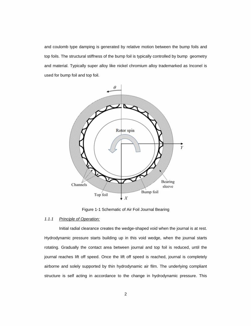
Figure 1-2 shows the components of the air foil thrust bearing. Thrust air foil
bearing is formed by number of circumferential sections called pad. Each pad consist a
pair of bump foil and top foil welded on the backing plate. Similar to journal bearing only
one end of bump foil and top foil are welded. The direction of rotation in thrust foil bearing
is opposite to that of air foil journal bearing; that is, rotation is from fixed end to free end.
The wedge-shaped void in air foil thrust bearing is formed by absence of bump foils at
leading edge or fixed end of the top foil. (Exaggerated detail view in Figure 1-2)
Figure 1-2 Air Foil Thrust Bearing, image from [2]
1.2.1 Principle of Operation:
The principle of operation of air foil thrust bearing is similar to the journal bearing.
Thrust foil bearing assembly consists of runner, which rotates between two thrust
bearings. At the beginning top foils are in contact with the runner, as the rotor speed
4
increases, hydrodynamics pressure starts building up, resulting in formation of thin air
film.
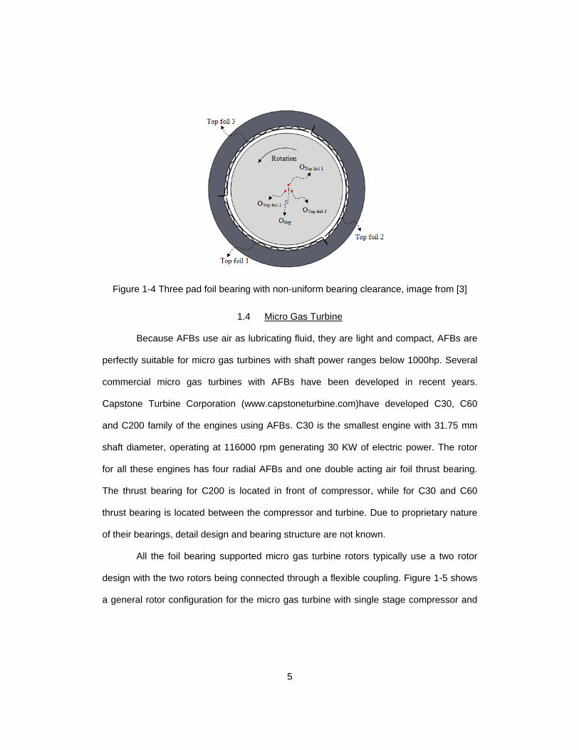
1.3 Multi-pad Air Foil Bearing
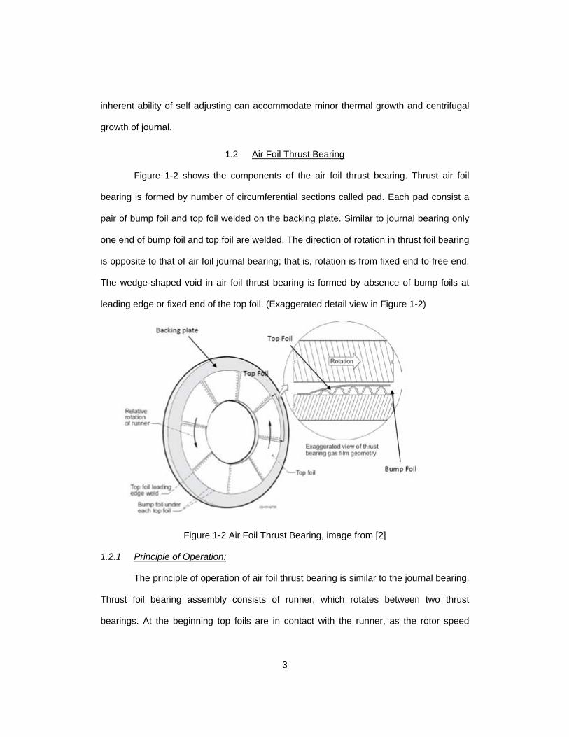
The bearing shown in Figure 1-1 is the single pad bearing. However, this bearing
cannot take load at the discontinuity of pad. In contrast, the multi-pad bearing shown in
Figure 1-3 can take load in many directions. In both these configurations, single pad and
multi-pad configuration, the radial clearance between top foil and rotor is uniform along
the circumferential direction if the bearing is lightly loaded. This uniform bearing
clearance leads the rotor to the instability at higher speeds. In order to avoid rotor
instability, it is important to have a bearing configuration with non uniform radial
clearance. Figure 1-4 shows the three-pad bearing with non uniform bearing clearance
along circumference. From the figure it can seen that the bearing center and top foil
center are not concentric, this amount of offset is termed as hydrodynamic offset which is
discussed in detail in section 3.2.
Figure 1-3 Multi-pad foil bearing, image from [1]
5
Figure 1-4 Three pad foil bearing with non-uniform bearing clearance, image from [3]
1.4 Micro Gas Turbine
Because AFBs use air as lubricating fluid, they are light and compact, AFBs are
perfectly suitable for micro gas turbines with shaft power ranges below 1000hp. Several
commercial micro gas turbines with AFBs have been developed in recent years.
Capstone Turbine Corporation (www.capstoneturbine.com)have developed C30, C60
and C200 family of the engines using AFBs. C30 is the smallest engine with 31.75 mm
shaft diameter, operating at 116000 rpm generating 30 KW of electric power. The rotor
for all these engines has four radial AFBs and one double acting air foil thrust bearing.
The thrust bearing for C200 is located in front of compressor, while for C30 and C60
thrust bearing is located between the compressor and turbine. Due to proprietary nature
of their bearings, detail design and bearing structure are not known.
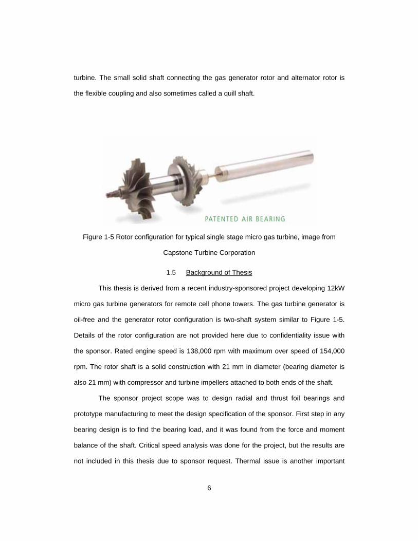
All the foil bearing supported micro gas turbine rotors typically use a two rotor
design with the two rotors being connected through a flexible coupling. Figure 1-5 shows
a general rotor configuration for the micro gas turbine with single stage compressor and
6
turbine. The small solid shaft connecting the gas generator rotor and alternator rotor is
the flexible coupling and also sometimes called a quill shaft.
Figure 1-5 Rotor configuration for typical single stage micro gas turbine, image from
Capstone Turbine Corporation
1.5 Background of Thesis
This thesis is derived from a recent industry-sponsored project developing 12kW
micro gas turbine generators for remote cell phone towers. The gas turbine generator is
oil-free and the generator rotor configuration is two-shaft system similar to Figure 1-5.
Details of the rotor configuration are not provided here due to confidentiality issue with
the sponsor. Rated engine speed is 138,000 rpm with maximum over speed of 154,000
rpm. The rotor shaft is a solid construction with 21 mm in diameter (bearing diameter is
also 21 mm) with compressor and turbine impellers attached to both ends of the shaft.
The sponsor project scope was to design radial and thrust foil bearings and
prototype manufacturing to meet the design specification of the sponsor. First step in any
bearing design is to find the bearing load, and it was found from the force and moment
balance of the shaft. Critical speed analysis was done for the project, but the results are
not included in this thesis due to sponsor request. Thermal issue is another important
7
design factor to be considered in the bearing design. Due to high speed operation, lot of
heat is generated in the bearing itself. In addition, heat conducted from the combustion
chamber and turbine impeller to the bearings and rotor also needs to be taken care of
through appropriate cooling system around the bearing. All these heat sources cause
thermal expansion of rotor and also bearing. When rotor thermal expansion far exceeds
that of bearing, bearing loses all the required clearance, hence leading to thermal
runaway and bearing seizure. A proper thermal management strategy should allow
similar thermal expansion of both shaft and bearing, and also cooling air flow through the
bearings should be minimized to allow better system efficiency. Comprehensive thermal
analysis was performed for entire bearing and engine housing during the project period,
and a thermal gradient of 75o C between bearing and sleeve was predicted.
At high speed operations, rotor stability is another important issue. Preliminary
analysis showed that the single pad foil bearings are not stable at design speed. In order
to tackle the rotor stability issue, an offset-preloaded two pad foil bearing configuration
with an existing bump design was adopted for the sponsor project.
Overall scope of the thesis is to measure stiffness and damping characteristics of
the existing bumps when they are used for the chosen two pad foil bearing and to find
design clearance and hydrodynamic preload (to be explained later) for the rotor to be
stable at design speed. More rigorous stability analysis including conical mode and
various external disturbances including impeller aerodynamic forces and non-linear effect
of gas film is on-going work in the project team. .
8
Chapter 2
Literature Review
This section presents the previous research and advancements in air foil
bearings. Extensive research has been carried out to study the effect of important
parameters such as load capacity, radial clearance, and thermal characteristics on gas
bearing performance. Heshmat et al [4] were first to present the hydrodynamic analysis of
foil bearings. They coupled the Reynolds equation with structural model of foils to
consider compliant bump foil structure in the static performance of foil thrust bearing.
Load capacity of foil bearing is the maximum constant load that can be supported
by the bearing operating with constant speed and steady state condition [5]. DellaCorte
and Valco [5] developed a rule of thumb for estimating the load capacity of the foil
bearing. Asperity contact and local friction was observed when the nominal clearance
approached the average roughness of the shaft and top foil surfaces. Taking this into
consideration and using the data available from previous experiments, the empirical
relationship was formulated.
Iordanoff [6] developed the analytical formula for evaluation of bump foil stiffness
for free end and clamped end. The analysis included the friction between top foil and
bump foil, sleeve and bump foil, and coupling forces between the adjacent bumps.
Radial clearance of the air foil bearing is important design characteristic affecting
the performance of the bearing. In contrast to the oil lubricated bearing, gas lubricated
bearings have very small radial clearance. However, foil bearing clearance is not visible
due to non-conformance of bump foil and top foil with the bearing sleeve and shaft [7].
Due to this reason, the radial clearance of AFB is measured by performing load deflection
test. The load-deflection test is performed with a test bearing assembled on to a rigid
shaft firmly fixed to stationary structure, and push-pull loading is applied against the
9
bearing to measure load-deflection curve of the bearing. Once the curve for load
deflection test is obtained, the boundary of null bearing stiffness marks the amount of
diametric clearance of the foil bearing. Radil et al [7] conducted the load capacity test on
bearings with different radial clearance measured using the above mentioned load-
deflection test. The test foil bearing floating on rotating shaft was loaded until the
dramatic change was observed in friction torque, this change in torque denoting the
rubbing contact and hence the maximum load capacity. It was observed that each test
bearing has optimum radial clearance with maximum load capacity. However, bearing
with insufficient clearance exhibited lower load capacity due to premature thermal
runaway. On the contrary, bearing with radial clearance twice the optimum suffered only
20% reduction in load capacity.
The compliant surface in foil bearing provides the tunable structural stiffness and
coulomb type damping. Heshmat et al [8] measured the bump foil stiffness and observed
that the bump foil stiffness depends on bump material, bump pitch and bump height.
Furthermore, San Andres et al. [9] investigated the difference in the structural stiffness
with different clearance. Load deflection curve was recorded for three different bearing
clearances: large clearance, zero clearance, and negative clearance (interference). It
was recorded that structural stiffness varied with the initial preload at low loads, while at
high load all three bearing exhibited the same structural stiffness.
Extensive, analytical and experimental research has been carried out to improve
the load capacity and stability of the air foil bearing. All the analytical studies performed
earlier assumed uniform bump stiffness distribution. To study the effect of variation of the
bump stiffness on load capacity and bearing performance, Kim [10] conducted a
parametric study on static and dynamic performance of foil bearing under variation of
bump stiffness and bearing geometry. Two geometric configurations were studied along
10
with stiffness variation in each sub configuration. Circular bearing with one continuous
bump foil and top foil and another bearing made with three sets of bump foils and top
foils. Furthermore each configuration had variable stiffness, with stiffness variation in
axial direction for first configuration and in circumferential direction for second
configuration. Average film thickness of 3 microns at the heavily loaded region was used
as criteria to record the maximum load capacity. From the load capacity analyses it was
recorded that stiffness variation had insignificant effect on the load capacity of the
bearing. On the contrary it was observed that geometric variation of bearing clearance
had significant effect on the load capacity, with significant drop in the load capacity for
three pad bearing. To investigate the dynamic performance of the bearing, frequency-
dependent bearing stiffness and damping coefficients was calculated using perturbation
method. The bump stiffness variation showed insignificant effect on force coefficients.
However, in comparison with single bump foil bearing, significant reduction in cross
coupled stiffness was recorded in the three pad foil bearing. Furthermore, stability
analyses of the single foil bearing and three pad bearing was conducted using time
domain orbit simulation. Higher onset speed of instability for the three pad bearing was
recorded, indicating better stability as compared to the single pad bearing.
Along with the bump foil, many other compliant structures for air foil bearings are
studied by researchers. Kim [11] introduced a new type of compliant structure by
replacing the bump foil with axially stretched compression spring. Analytical and
experimental studies were conducted to determine load capacity, structural stiffness and
damping coefficients of the bearing. In addition, a new method of cooling was introduced
and cooling effectiveness was studied by testing bearing at 20000 rpm with and without
cooling.
11
Metal mesh material is another alternative compliant structure studied by
researchers. Metal mesh foil bearing consists of top foil resting on the metal mesh pad.
These metal mesh pads are formed by compressing the weave metal wire. Lee et al [12]
estimated the linear stiffness coefficient and damping loss factor for the metal mesh foil
bearing with three mesh densities of 13.1 %, 23.2 % and 31.6 % .They conducted load
deflection test for each configuration at 0 rpm and 30000 rpm. Load deflection curve for
loading and unloading cycle was further used to calculate linear stiffness, and damping
loss factor was evaluated using area enclosed in hysteresis loop. The results showed
highest linear stiffness and damping loss factor for higher mesh density at 0 rpm, and
slight decrease in values at 30000 rpm.
Thermal management of air foil bearing (AFB) is another area which has been
studied extensively by researchers. In order to get a better insight into heat generation in
AFB, Radil et al [13] conducted experiments to determine the temperature profile in AFB.
Temperature profile of the bearing was measured using 9 thermocouples arranged in 3
sets on center and edges of the bearing. They conducted tests for speeds ranging from
20,000 to 50,000 rpm and load from 9 to 222 N. The results indicated both journal speed
and load increases the bearing temperature with journal speed having the most
significant effect.
Kim and Lee [14] developed a 3D thermohydrodynamic model for air foil bearing
to predict the temperature of the rotor, bump foil, top foil, bearing sleeve and air film. The
channel formed by the region between adjacent bumps and top foil was defined as
primary channel and bump foil channel as secondary channel. They modeled these
channels as plate fin heat exchanger. Effective heat transfer resistance from top foil to
bearing sleeve was measured experimentally and used in model. In addition to this,
thermal growth of bump foil, top foil and shaft was also included in the model. Using this
12
model, further parametric studies were conducted by varying clearance, load, rotor speed
and cooling air flow conditions. Their study concluded that rotor temperature increased
with decrease in bearing clearance and increased with increase in load and rotor speed.
In addition, the thermal expansion of the bump foil and top foil only accounted less than 1
% decrease in the clearance, while the rotor thermal expansion accounts for 20 %
decrease in the clearance.
2.1 Research Objective
As discussed in previous section, Kim [10] conducted the parametric studies to
investigate the effect of variation of bump stiffness and top foil geometry. The reports
indicated that variation of bump stiffness has insignificant effect on bearing
characteristics, while the change in top foil geometry (radial clearance) showed
significant impact on overall bearing performance. The bearing with continuous top foil
exhibited better load capacity as compared to three pad bearing. However, three pad
bearing exhibited higher onset speed of instability.
In order to maximize load capacity and to have better rotordynamic performance,
an offset-preloaded two pad foil bearing was chosen for the sponsored project;
developing 12kW gas turbine generators.
Design parameters of the offset-preloaded two pad bearings are not as simple as
the circular single pad foil bearings. Once the bump stiffness is known, clearance,
preload, and pivot offset values have to be determined. This thesis presents design study
of the bearing in terms of these parameters using experimentally-measured bump
stiffness and damping characteristics. Unlike ball bearings, AFBs are custom designed
for specific operating conditions including load and its direction. The loading direction
decides the orientation of the bearing, hence, the AFB will not perform as predicted if the
orientation of the bearing is different from that of the designed orientation. The thesis also
13
investigates the dynamic characteristics of the designed offset-preloaded two pad
bearing under different orientations with respect to the loading direction. Linearized
Reynolds equation is used to calculate frequency dependent stiffness coefficients and
damping coefficients for the bearing.
.
14
Chapter 3
Configuration and Manufacturing of Foil Bearing
As discussed in the previous chapter, researchers have carried out extensive
analytical and experimental studies to evaluate the effect of bearing parameters on load
capacity, force coefficients and stability of bearing. This chapter presents the design
considerations and manufacturing process of the offset-preloaded two pad air foil
bearings with 21 mm in diameter.
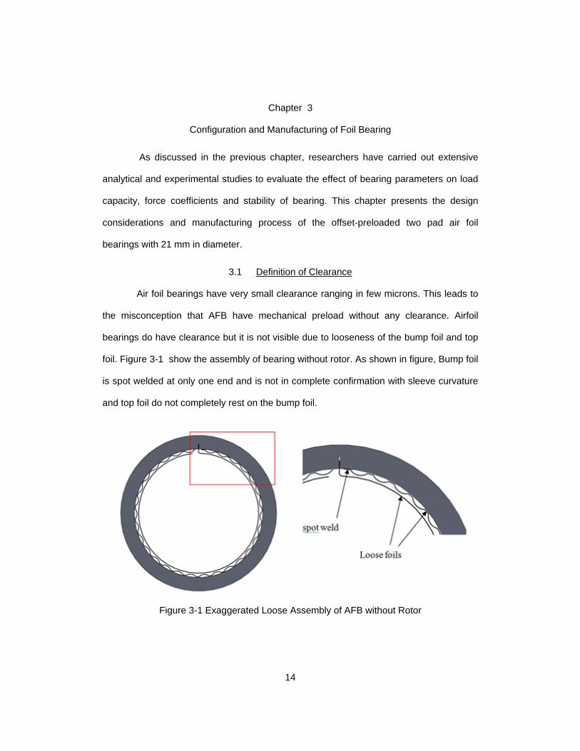
3.1 Definition of Clearance
Air foil bearings have very small clearance ranging in few microns. This leads to
the misconception that AFB have mechanical preload without any clearance. Airfoil
bearings do have clearance but it is not visible due to looseness of the bump foil and top
foil. Figure 3-1 show the assembly of bearing without rotor. As shown in figure, Bump foil
is spot welded at only one end and is not in complete confirmation with sleeve curvature
and top foil do not completely rest on the bump foil.
Figure 3-1 Exaggerated Loose Assembly of AFB without Rotor
15
When the shaft is assembled in the bearing all these loose assemblies make
weak contact, which means they can retract even with small pressure, accounting for the
cold assembly clearance. This assembly clearance is used for numerical modeling and
analyses of AFB. To accurately measure this clearance, NASA engineer suggested using
experimental load-deflection curve and identify the cold assembly clearance from soft
region of the load-deflection curve. Details of the load-deflection test will be presented
later.
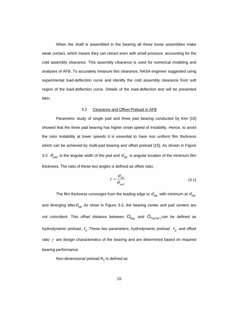
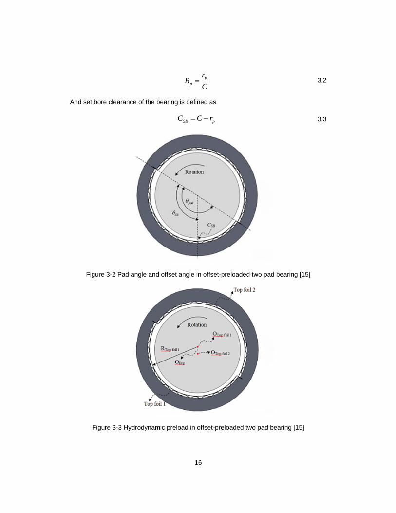
3.2 Clearance and Offset Preload in AFB
Parametric study of single pad and three pad bearing conducted by Kim [10]
showed that the three pad bearing has higher onset speed of instability. Hence, to avoid
the rotor instability at lower speeds it is essential to have non uniform film thickness
which can be achieved by multi-pad bearing and offset preload [15]. As shown in Figure
3-2 padθ is the angular width of the pad and SBθ is angular location of the minimum film
thickness. The ratio of these two angles is defined as offset ratio;
SB
pad
θγθ
=
(3.1)
The film thickness converges from the leading edge to SBθ with minimum at SBθ
and diverging after SBθ .As show in Figure 3-3, the bearing center and pad centers are
not coincident. This offset distance between BrgO and 1Top foilO can be defined as
hydrodynamic preload, pr .These two parameters, hydrodynamic preload pr and offset
ratio γ are design characteristics of the bearing and are determined based on required
bearing performance.
Non-dimensional preload Rp is defined as
16
p
p
rR
C= 3.2
And set bore clearance of the bearing is defined as
SB pC C r= − 3.3
Figure 3-2 Pad angle and offset angle in offset-preloaded two pad bearing [15]
Figure 3-3 Hydrodynamic preload in offset-preloaded two pad bearing [15]
17
Because centrifugal growth and thermal expansion of the shaft are not negligible,
they have to be considered in selecting the foil bearing clearance. When cold assembly
clearance is too small, centrifugal growth and thermal expansion of the shaft can lead to
thermal runaway and bearing seizure.
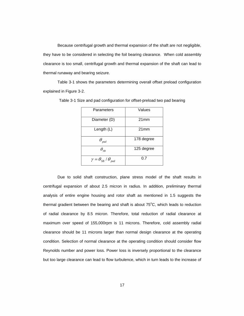
Table 3-1 shows the parameters determining overall offset preload configuration
explained in Figure 3-2.
Table 3-1 Size and pad configuration for offset-preload two pad bearing
Parameters Values
Diameter (D) 21mm
Length (L) 21mm
padθ
178 degree
SBθ 125 degree
/SB padγ θ θ=
0.7
Due to solid shaft construction, plane stress model of the shaft results in
centrifugal expansion of about 2.5 micron in radius. In addition, preliminary thermal
analysis of entire engine housing and rotor shaft as mentioned in 1.5 suggests the
thermal gradient between the bearing and shaft is about 75oC, which leads to reduction
of radial clearance by 8.5 micron. Therefore, total reduction of radial clearance at
maximum over speed of 155,000rpm is 11 microns. Therefore, cold assembly radial
clearance should be 11 microns larger than normal design clearance at the operating
condition. Selection of normal clearance at the operating condition should consider flow
Reynolds number and power loss. Power loss is inversely proportional to the clearance
but too large clearance can lead to flow turbulence, which in turn leads to the increase of
18
power loss. Table 3-2 summarizes the range of hydrodynamic preload and clearances
that were used in simulations in Chapter 4.
Table 3-2 Radial clearance and preload
∆C due to centrifugal expansion @ 155,000rpm - 2.5 µm
Thermal gradient between bearing and sleeve 75oC
∆C due to thermal gradient @ 155,000rpm - 8.5 µm
Range of sleeve preload, pr 40~52 µm (40 43, 46, 49, 52)
Total ∆C - 11 µm
Cold assembly radial clearance @ 0 rpm 68.5~80.5 µm
Hot assembly radial clearance @ 0 rpm 60~72 µm (60, 63, 66, 69, 72)
Operating radial clearance @ 155,000 rpm 57.5~69.5 µm
3.3 Manufacturing Process of Foil Bearing
Bearing assembly consists of following components:
• Bump Foil
• Top Foil
• Bearing Sleeve
3.3.1 Bump Foil
Bump foil is corrugated compliant structure supporting the top foil. 0.003" thick
sheet metal of Nickel-Chromium super alloy trade named Inconel 718 is used for making
the bump foils. Two identical bump foils each consisting of 17 bumps is formed by cold
forming process. Form-Feed-Hold-Form process is followed for forming the bump foil. As
shown in the Figure 3-4 (a), first a plane blank is pressed in the forming jig to form 5
bumps. For forming process 8 tons of pressure is applied using hydraulic press. These

19
formed bumps are then fed into holding region of the forming jig to constrain the pulling-in
of formed bumps into forming region. In order to have uniform bump height distribution it
was ensured that each bump passes through middle section of the forming jig.
(a) (b)
Figure 3-4 Form-Feed-Hold-Form (a) Forming of bumps (b) Formed bumps are held in
holding region of jig
Figure 3-5 Bump foils
3.3.2 Top Foil
Offset-preloaded two pad bearing has two top foils. These two top foils are
identical and made of same material as that of bump foils. Each top foil covers the span
of 175o. In order to get the desired curvature, the top foil blank is wrapped to a mandrel
20
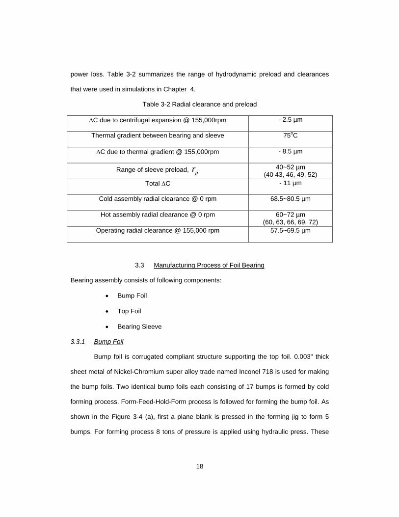
having smaller diameter then the required curvature. This mandrel along with wrapped
foil is then pressed in the top foil forming jig shown Figure 3-6. A small lip is formed one
end of the top foil to ensure easy assembly/disassembly of the top foil in to the bearing
sleeve. (Refer Figure 3-9)
Figure 3-6 Top foil forming jig 1
Figure 3-7 Top foil lip forming jig 2
21
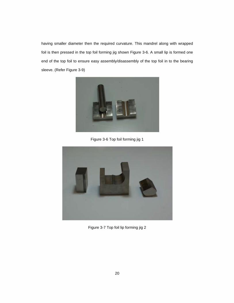
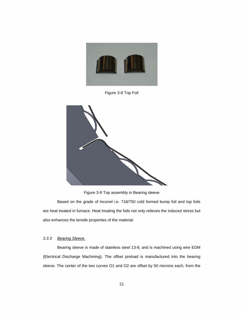
Figure 3-8 Top Foil
Figure 3-9 Top assembly in Bearing sleeve
Based on the grade of Inconel i.e. 718/750 cold formed bump foil and top foils
are heat treated in furnace. Heat treating the foils not only relieves the induced stress but
also enhances the tensile properties of the material.
3.3.3 Bearing Sleeve.
Bearing sleeve is made of stainless steel 13-8, and is machined using wire EDM
(Electrical Discharge Machining). The offset preload is manufactured into the bearing
sleeve. The center of the two curves O1 and O2 are offset by 50 microns each, from the
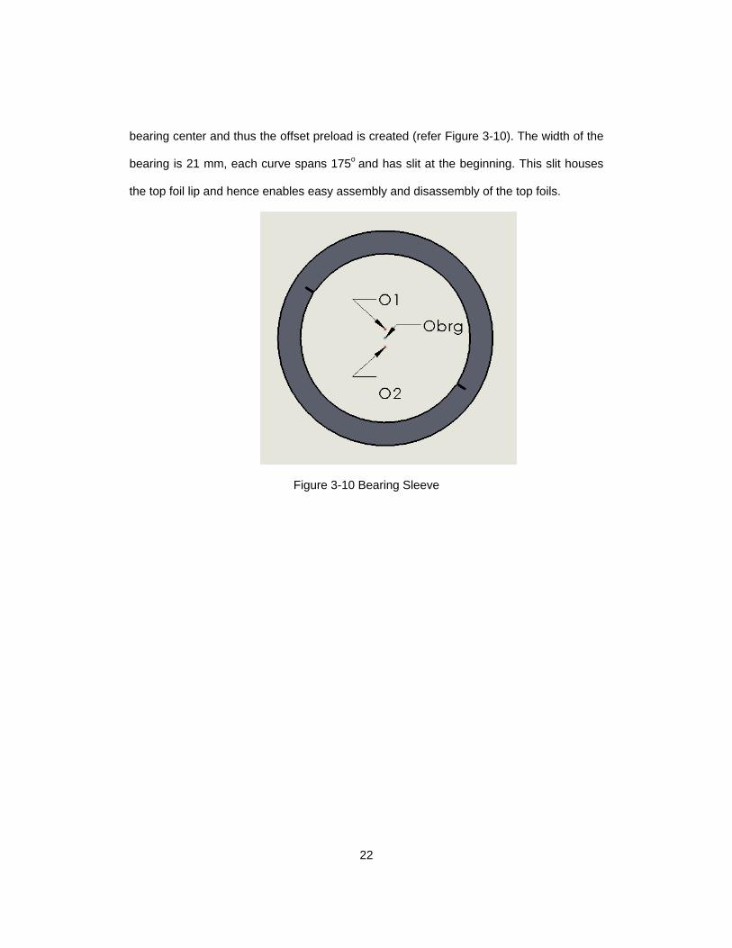
22
bearing center and thus the offset preload is created (refer Figure 3-10). The width of the
bearing is 21 mm, each curve spans 175o and has slit at the beginning. This slit houses
the top foil lip and hence enables easy assembly and disassembly of the top foils.
Figure 3-10 Bearing Sleeve
23
Chapter 4
Gas Film Lubrication Theory
This chapter presents mathematical theory used in the simulation and modal
impedance curves presented in Chapter 5. All the theory and formulations presented in
this chapter is based on the class notes of ME5390 Applied Tribology taught by Dr.
Daejong Kim.
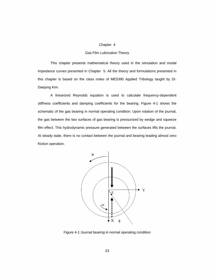
A linearized Reynolds equation is used to calculate frequency-dependent
stiffness coefficients and damping coefficients for the bearing. Figure 4-1 shows the
schematic of the gas bearing in normal operating condition. Upon rotation of the journal,
the gas between the two surfaces of gas bearing is pressurized by wedge and squeeze
film effect. This hydrodynamic pressure generated between the surfaces lifts the journal.
At steady state, there is no contact between the journal and bearing leading almost zero
friction operation.
Figure 4-1 Journal bearing in normal operating condition
24
4.1 Reynolds Equation
Standard governing equation for thin gas film is Reynolds equation developed by
Osborne Reynolds in 1886with assumptions of thin gas film, negligible curvature effect
and isothermal ideal gas;
)(12)(6)()( 33 pht
phx
Uzpph
zxpph
x ∂∂
+∂∂
=∂∂
∂∂
+∂∂
∂∂ µµ
(4.1)
4.2 Stiffness and Damping Coefficient Equation
Dynamic performance of the bearing is usually done by calculating the bearing
stiffness and damping coefficients. Perturbation method is used to calculate frequency-
dependent force coefficients. In perturbation analysis the rotor at static equilibrium
0 0,X Ye e is given finitely small disturbance of amplitude ,x ye e∆ ∆ with excitation
frequency sω . Once the equilibrium position 0 0,X Ye e is found, perturbed eccentricity,
bump deflection and local thickness is given by following set of equation
0 , ,si te e e e X Yω
α α α α= + ∆ = (4.2)
0
s si t i tX Yu u u e u eω ω= + ∆ + ∆ (4.3)
0
s si t i tX Yh h h e h eω ω= + ∆ + ∆ (4.4)
Where
0000 sincos ueeCh YX +++= θθ
(4.5)
XXX ueh ∆+∆=∆ θcos
(4.6)
YYY ueh ∆+∆=∆ θsin
(4.7)
25
From the perturbed form of film thickness, perturbed pressure is given as
0
s si t i tX X Y Yp p e p e e p eω ω= + ∆ + ∆ (4.8)
For actual numerical analysis, it is easier to use non-dimensionalized equations.
Firstly, Reynolds equation is non-dimensionalized as.
3 3( ) ( ) ( ) 2 ( )s
P PPH PH PH PHZ Z
νθ θ θ τ∂ ∂ ∂ ∂ ∂ ∂
+ = Λ + Λ∂ ∂ ∂ ∂ ∂ ∂
(4.9)
where ap
pP = , ChH = ,
Ce
=ε , ωω
ν s= , 26
a
Rp Cµω Λ =
and s stτ ω= . The
perturbed pressure, film thickness, and bump deflections are also non-dimensionalized
such as
0 0
S Si iX X Y YP P P P P e P eτ τε ε= + ∆ = + ∆ + ∆ (4.10)
0 0
S Si iX YH H H H H e H eτ τ= + ∆ = + ∆ + ∆
(4.11)
0
S Si iX YU U U e U eτ τ= + ∆ + ∆
(4.12)
where uUC
= . Inserting non-dimensional form of perturbed pressure, film thickness and
bump deflections into non-dimensional Reynolds equation and dropping all the higher
terms and rearranging
( ) ( )
( ) ( )
3 30 0 0 0
2 3 2 30 00 0 0 0 0 0
0 0 0 0
3 3
2
P PP H P HZ Z
P PH P H H P H P H H PZ Z
P H P H i P H P H
α α
α α α α
α α α α
θ θ
θ θ
νθ
∂ ∂∂ ∂ + + ∂ ∂ ∂ ∂ ∂ ∂ ∂ ∂ + + + = ∂ ∂ ∂ ∂ ∂
Λ + + Λ +∂
(4.13)
Where
26
, ,HH X Yα
αα
αε
∆≡ =∆
(4.14)
Equation for bump dynamics is given as
b b b
duf k u cdt
= +
(4.15)
In above equation bc is equivalent bump viscous damping coefficient calculated using
loss factor η and bump stiffness bk ;s
bb
kc
ωη= Also bf is bump pressure given as
=b of pA ,substituting all this in equation (4.15) gives
0
bb
s
k dupA k udt
ηω
= +
(4.16)
Non-dimensionalizing above equation gives
b b b
s s
dU dUP K U C K Ud d
ν ητ τ
= + = +
(4.17)
where 0
bb
a
k CKp A
= , 0
bb b
a s
k CC Kp Aη ω η
ω ν= = . Inserting equation (4.10) and (4.12) in above
equation and canceling zeroth order term.
(1 ) (1 )X X Y Y b X b YP P K i U K i Uε ε η η∆ + ∆ = + ∆ + + ∆ (4.18)
Inserting θε cosXXX HU ∆−∆=∆ and θε sinYYY HU ∆−∆=∆ and separating X and Y
components.
( )( )
(1 ) cos
(1 ) sinX X b X X
Y Y b Y Y
P K i H
P K i H
ε η ε θ
ε η ε θ
∆ = + ∆ −∆
∆ = + ∆ −∆
(4.19)
Dividing above equation by αε∆ gives
27
cos
(1 )X
Xb
PHK i
θη
= ++
(4.20)
sin
(1 )Y
Yb
PHK i
θη
= ++
(4.21)
Inserting equation (4.20) and (4.21) into (4.13) and rearranging
3 30 0 0 0 0
3 20 00 0 0 0
3 20 00 0 0
0
3(1 ) (1 )
3(1 )
2(1 )
b b
b
b
P PH P P H P HZ Z
P P P PH P P f H P fK i K i
P P PH P H P fZ Z K i Z
Pi P f PK i
α αα
α αα α α
αα α
αα α
θ θ
θ θ η η θ
η
νη
∂ ∂∂ ∂ Λ − + − ∂ ∂ ∂ ∂ ∂ ∂∂
= −Λ + + + ∂ ∂ + + ∂ ∂ ∂∂
+ + + ∂ ∂ + ∂
− Λ + + +
0H
(4.22)
Where YX ,=α and θθ sin,cos == YX ff
0 0cos
Re( )sin2
θθ
θ
= − =
∫∫XX XXX
YX YX
k KW WR P d dZk KC L C
(4.23)
0 0cos
Re( )sin2
θθ
θ
= − =
∫∫XY XYY
YY YY
k KW WR P d dZk KC L C
(4.24)
0 0cos1 1Im( )
sin2θ
θθω ω
= − =
∫∫XX XX
XYX YXs s
d DW WR P d dZd DC L C
(4.25)
0 0cos1 1Im( )
sin2θ
θθω ω
= − =
∫∫XY XY
YYY YYs s
d DW WR P d dZd DC L C
(4.26)
Where 0 2∆ = aW P RL
28
4.3 Modal Impedance
Stability analysis of the bearing is performed by conducting modal analysis of
cylindrical mode of rigid rotor. Conical mode shape is out of scope in this thesis due to
sponsor request that the rotor geometry (bearing span and moment of inertia) is
confidential information.
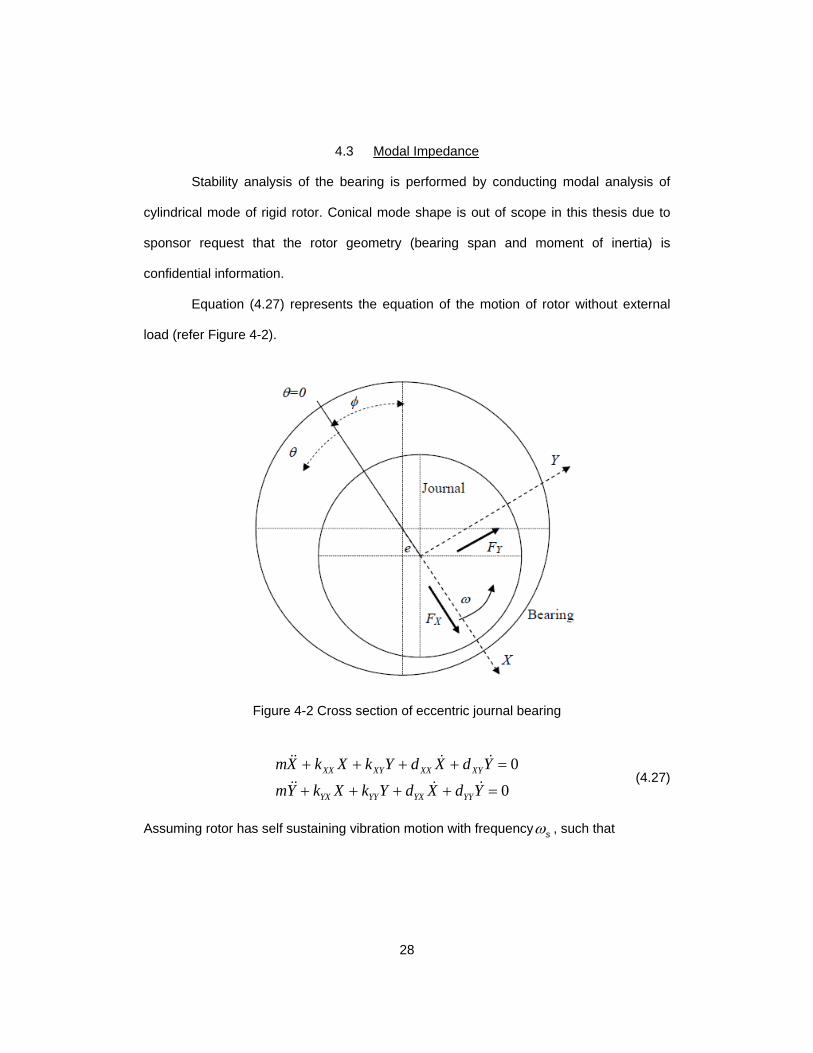
Equation (4.27) represents the equation of the motion of rotor without external
load (refer Figure 4-2).
Figure 4-2 Cross section of eccentric journal bearing
0
0XX XY XX XY
YX YY YX YY
mX k X k Y d X d YmY k X k Y d X d Y
+ + + + =
+ + + + =
(4.27)
Assuming rotor has self sustaining vibration motion with frequencyωs , such that

29
( )Re
( )sj tX t X
eY t Y
ωδδ
=
(4.28)
Where Re is real operator and ,X Yδ δ are phasors with magnitude and phase angle,
Inserting equation (4.28) into (4.27) we get
2
2
00
0XX XY
YX YY
Z ZX XmsZ XY Yms
δ δδ δ
+ =
(4.29)
Where ss jω= and Z contains both stiffness and damping coefficients,
XX XX XX s
YX YX YX s
XY XY XY s
YY YY YY s
Z K jdZ K jdZ K jdZ K jd
ωωωω
= += += += +
(4.30)
Assuming 2KZ ms= − and rearranging equation (4.29) we get
0XX K XY
YX YY K
Z Z Z XZ X Z Y
δδ
− = −
(4.31)
In order to have solution for above the 2 X 2 matrix must be zero.
2
( )( ) 0
( ) 0XX K YY K XY YX
K XX YY K XX YY XY YX
Z Z Z Z Z ZZ Z Z Z Z Z Z Z
− − − =
− + + − = (4.32)
Hence solution for above equation is given by
2
1
2
2
( )2 2
( )2 2
XX YY XX YYXX YY XY YX
XX YY XX YYXX YY XY YX
Z Z Z ZZ Z Z Z Z
Z Z Z ZZ Z Z Z Z
+ + = + − −
+ + = − − −
(4.33)
Results of the simulations are presented in 5.4.
30
Chapter 5
Results and Discussion
5.1 Structural Characterization
From the gas lubrication theory mentioned in the previous chapter, bump foil
stiffness and damping loss factor are required to study the dynamic characteristics of
AFB. This section explains how the bump stiffness was measured.
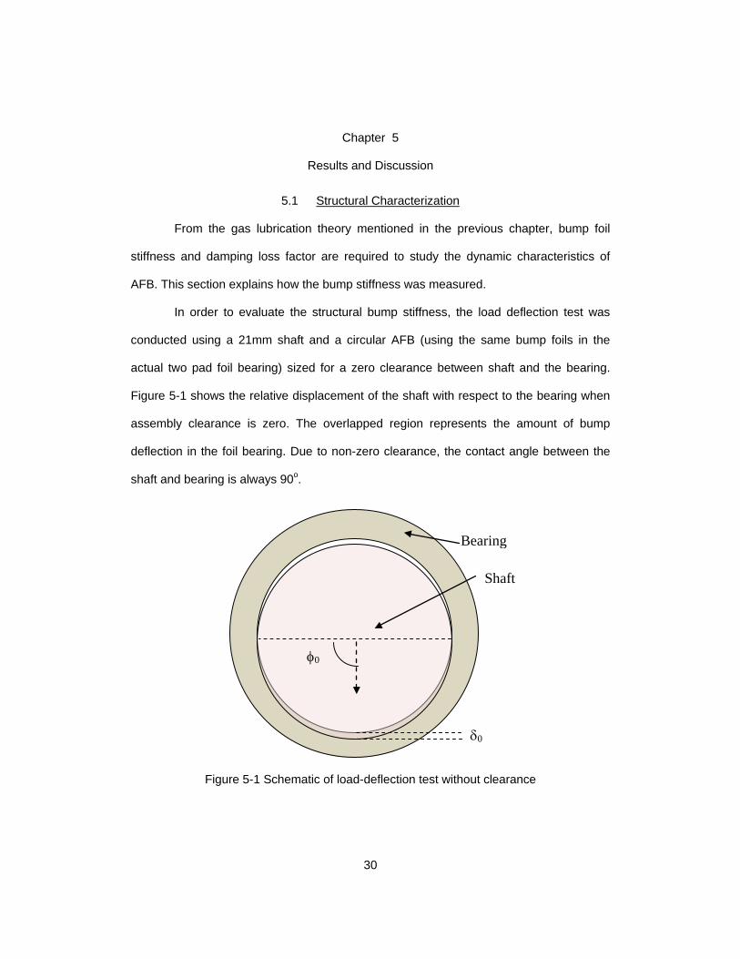
In order to evaluate the structural bump stiffness, the load deflection test was
conducted using a 21mm shaft and a circular AFB (using the same bump foils in the
actual two pad foil bearing) sized for a zero clearance between shaft and the bearing.
Figure 5-1 shows the relative displacement of the shaft with respect to the bearing when
assembly clearance is zero. The overlapped region represents the amount of bump
deflection in the foil bearing. Due to non-zero clearance, the contact angle between the
shaft and bearing is always 90o.
Figure 5-1 Schematic of load-deflection test without clearance
Bearing
Shaft
φ0
δ0
31
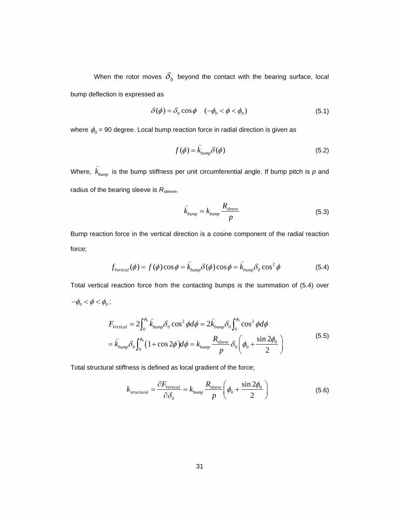
When the rotor moves 0δ beyond the contact with the bearing surface, local
bump deflection is expressed as
0 0 0( ) cos ( )δ φ δ φ φ φ φ= − < < (5.1)
where 0φ = 90 degree. Local bump reaction force in radial direction is given as
( ) ( )bumpf kφ δ φ=
(5.2)
Where, bumpk
is the bump stiffness per unit circumferential angle. If bump pitch is p and
radius of the bearing sleeve is Rsleeve,
sleevebump bump
Rk kp
=
(5.3)
Bump reaction force in the vertical direction is a cosine component of the radial reaction
force;
20( ) ( ) cos ( ) cos cosVertical bump bumpf f k kφ φ φ δ φ φ δ φ= = =
(5.4)
Total vertical reaction force from the contacting bumps is the summation of (5.4) over
0 0φ φ φ− < < ;
( )
0 0
0
2 20 00 0
00 0 00
2 cos 2 cos
sin 21 cos 22
Vertical bump bump
sleevebump bump
F k d k d
Rk d kp
φ φ
φ
δ φ φ δ φ φ
φδ φ φ δ φ
= =
= + = +
∫ ∫
∫
(5.5)
Total structural stiffness is defined as local gradient of the force;
0
00
sin 22
Vertical sleevestructural bump
F Rk kp
φφδ
∂ = = + ∂ (5.6)
32
The structuralk of the bump foil was evaluated experimentally and using equation
(5.6) bumpk was calculated. This bumpk was further used for stiffness and damping
coefficient evaluations and modal analysis of bearing.
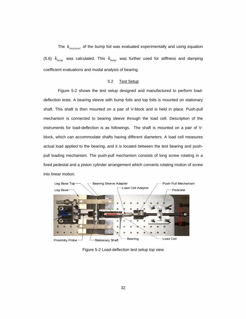
5.2 Test Setup
Figure 5-2 shows the test setup designed and manufactured to perform load-
deflection tests. A bearing sleeve with bump foils and top foils is mounted on stationary
shaft. This shaft is then mounted on a pair of V-block and is held in place. Push-pull
mechanism is connected to bearing sleeve through the load cell. Description of the
instruments for load-deflection is as followings. The shaft is mounted on a pair of V-
block, which can accommodate shafts having different diameters. A load cell measures
actual load applied to the bearing, and it is located between the test bearing and push-
pull loading mechanism. The push-pull mechanism consists of long screw rotating in a
fixed pedestal and a piston cylinder arrangement which converts rotating motion of screw
into linear motion.
Figure 5-2 Load-deflection test setup top view
33
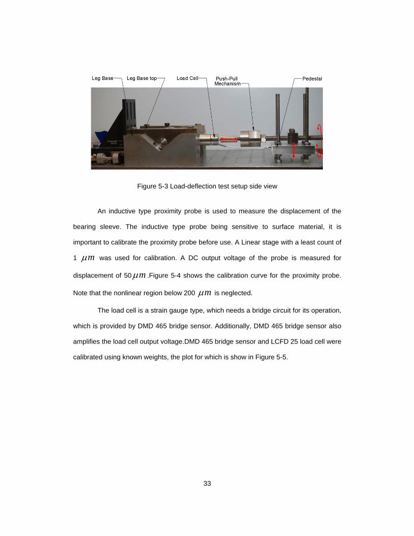
Figure 5-3 Load-deflection test setup side view
An inductive type proximity probe is used to measure the displacement of the
bearing sleeve. The inductive type probe being sensitive to surface material, it is
important to calibrate the proximity probe before use. A Linear stage with a least count of
1 mµ was used for calibration. A DC output voltage of the probe is measured for
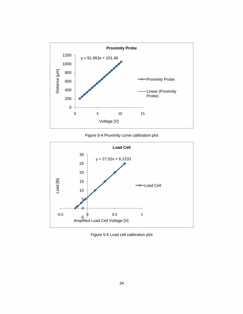
displacement of 50 mµ .Figure 5-4 shows the calibration curve for the proximity probe.
Note that the nonlinear region below 200 mµ is neglected.
The load cell is a strain gauge type, which needs a bridge circuit for its operation,
which is provided by DMD 465 bridge sensor. Additionally, DMD 465 bridge sensor also
amplifies the load cell output voltage.DMD 465 bridge sensor and LCFD 25 load cell were
calibrated using known weights, the plot for which is show in Figure 5-5.
34
Figure 5-4 Proximity curve calibration plot
Figure 5-5 Load cell calibration plot
y = 91.963x + 101.46
0
200
400
600
800
1000
1200
0 5 10 15
Dis
tanc
e [µ
m]
Voltage [V]
Proximity Probe
Proximity Probe
Linear (Proximity Probe)
y = 27.52x + 6.1233
-5
0
5
10
15
20
25
30
-0.5 0 0.5 1
Load
[lb]
Amplified Load Cell Voltage [V]
Load Cell
Load Cell
35
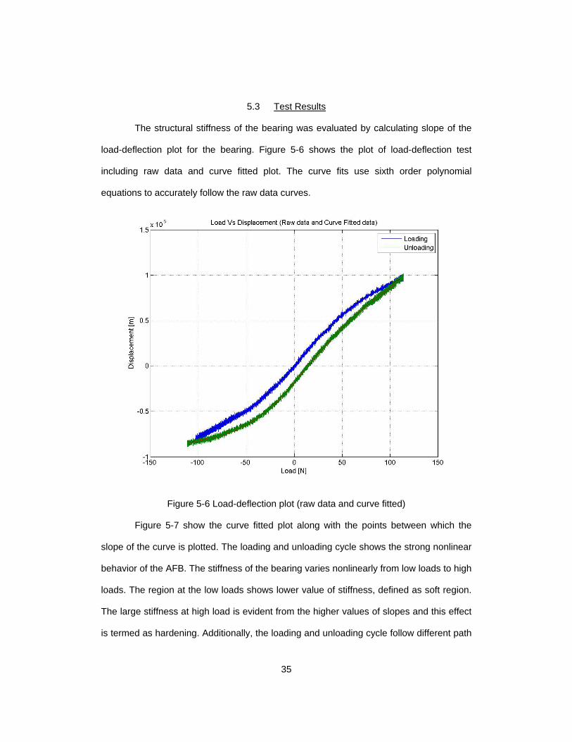
5.3 Test Results
The structural stiffness of the bearing was evaluated by calculating slope of the
load-deflection plot for the bearing. Figure 5-6 shows the plot of load-deflection test
including raw data and curve fitted plot. The curve fits use sixth order polynomial
equations to accurately follow the raw data curves.
Figure 5-6 Load-deflection plot (raw data and curve fitted)
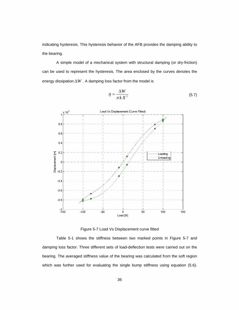
Figure 5-7 show the curve fitted plot along with the points between which the
slope of the curve is plotted. The loading and unloading cycle shows the strong nonlinear
behavior of the AFB. The stiffness of the bearing varies nonlinearly from low loads to high
loads. The region at the low loads shows lower value of stiffness, defined as soft region.
The large stiffness at high load is evident from the higher values of slopes and this effect
is termed as hardening. Additionally, the loading and unloading cycle follow different path
36
indicating hysteresis. This hysteresis behavior of the AFB provides the damping ability to
the bearing.
A simple model of a mechanical system with structural damping (or dry-friction)
can be used to represent the hysteresis. The area enclosed by the curves denotes the
energy dissipation W∆ . A damping loss factor from the model is
2
Wk X
ηπ∆
= (5.7)
Figure 5-7 Load Vs Displacement curve fitted
Table 5-1 shows the stiffness between two marked points in Figure 5-7 and
damping loss factor. Three different sets of load-deflection tests were carried out on the
bearing. The averaged stiffness value of the bearing was calculated from the soft region
which was further used for evaluating the single bump stiffness using equation (5.6).
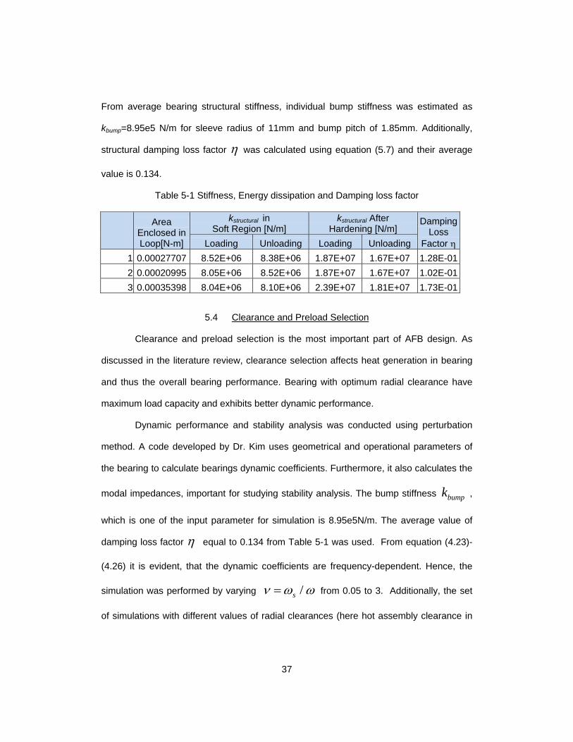
37
From average bearing structural stiffness, individual bump stiffness was estimated as
kbump=8.95e5 N/m for sleeve radius of 11mm and bump pitch of 1.85mm. Additionally,
structural damping loss factor η was calculated using equation (5.7) and their average
value is 0.134.
Table 5-1 Stiffness, Energy dissipation and Damping loss factor
Area Enclosed in Loop[N-m]
kstructural in Soft Region [N/m]
kstructural After Hardening [N/m]
Damping Loss
Factor η Loading Unloading Loading Unloading 1 0.00027707 8.52E+06 8.38E+06 1.87E+07 1.67E+07 1.28E-01 2 0.00020995 8.05E+06 8.52E+06 1.87E+07 1.67E+07 1.02E-01 3 0.00035398 8.04E+06 8.10E+06 2.39E+07 1.81E+07 1.73E-01
5.4 Clearance and Preload Selection
Clearance and preload selection is the most important part of AFB design. As
discussed in the literature review, clearance selection affects heat generation in bearing
and thus the overall bearing performance. Bearing with optimum radial clearance have
maximum load capacity and exhibits better dynamic performance.
Dynamic performance and stability analysis was conducted using perturbation
method. A code developed by Dr. Kim uses geometrical and operational parameters of
the bearing to calculate bearings dynamic coefficients. Furthermore, it also calculates the
modal impedances, important for studying stability analysis. The bump stiffness bumpk ,
which is one of the input parameter for simulation is 8.95e5N/m. The average value of
damping loss factor η equal to 0.134 from Table 5-1 was used. From equation (4.23)-
(4.26) it is evident, that the dynamic coefficients are frequency-dependent. Hence, the
simulation was performed by varying /sν ω ω= from 0.05 to 3. Additionally, the set
of simulations with different values of radial clearances (here hot assembly clearance in
38
Table 3-2 was used as reference) and preloads were simulated. The radial clearance
was varied from 60 mµ to 72 mµ and preload was varied from 40 mµ to 52 mµ with
an increment of 3 mµ .
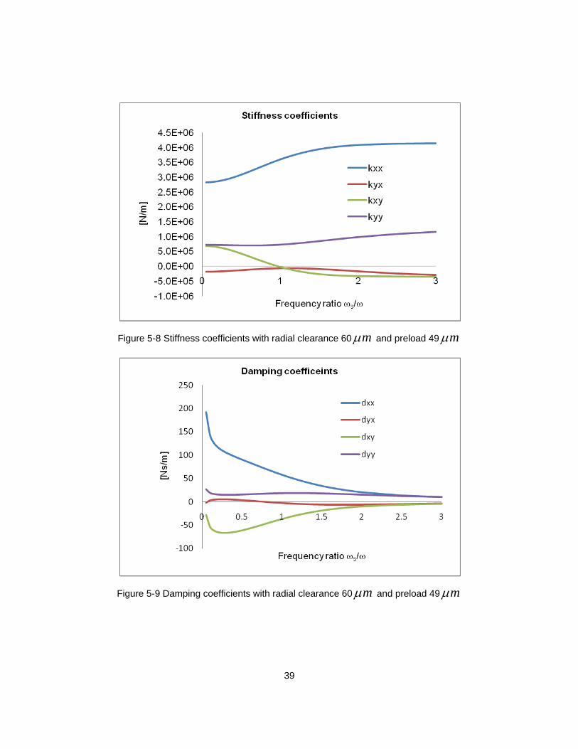
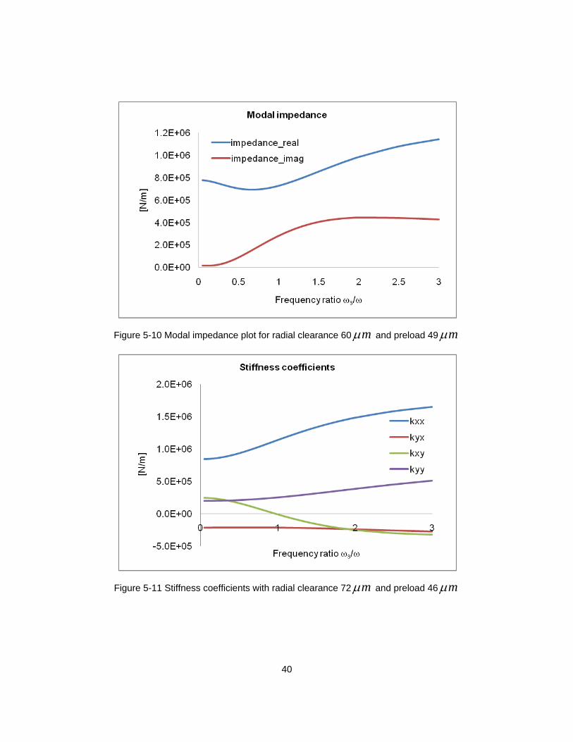
Figure 5-8 ~ Figure 5-10 shows the plot for stiffness coefficients, damping
coefficients and modal impedance for radial clearance 60 mµ and preload 49 mµ .
From the stiffness and damping plots it is evident that the bearing has higher direct
coefficients and lower cross-coupled coefficients, indicating that the bearing is stable.
Furthermore, the absence of negative imaginary impedance or unstable eigenmode
confirms the bearing stability.
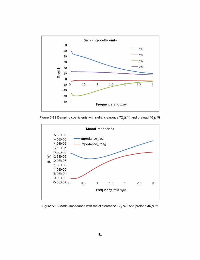
Figure 5-11~Figure 5-13 shows the plot for stiffness coefficients, damping
coefficients and modal impedance for radial clearance 72 mµ and preload 46 mµ .
Although, in this case the direct coefficients are higher than the cross-coupled
coefficients they are lower than the previous case. Also from the modal impedance this
bearing has unstable eigenmode at ν below around 0.3. Hence the bearing with this
combination of clearance and preload is susceptible to instability.
39
Figure 5-8 Stiffness coefficients with radial clearance 60 mµ and preload 49 mµ
Figure 5-9 Damping coefficients with radial clearance 60 mµ and preload 49 mµ
40
Figure 5-10 Modal impedance plot for radial clearance 60 mµ and preload 49 mµ
Figure 5-11 Stiffness coefficients with radial clearance 72 mµ and preload 46 mµ
41
Figure 5-12 Damping coefficients with radial clearance 72 mµ and preload 46 mµ
Figure 5-13 Modal impedance with radial clearance 72 mµ and preload 46 mµ
42
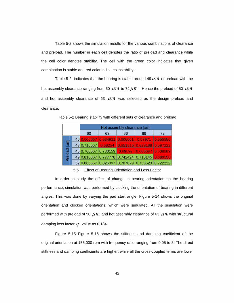
Table 5-2 shows the simulation results for the various combinations of clearance
and preload. The number in each cell denotes the ratio of preload and clearance while
the cell color denotes stability. The cell with the green color indicates that given
combination is stable and red color indicates instability.
Table 5-2 indicates that the bearing is stable around 49 mµ of preload with the
hot assembly clearance ranging from 60 mµ to 72 mµ . Hence the preload of 50 mµ
and hot assembly clearance of 63 mµ was selected as the design preload and
clearance.
Table 5-2 Bearing stability with different sets of clearance and preload
Hot assembly clearance [µm]
60 63 66 69 72
Prel
oad
[µm
] 40 0.666667 0.634921 0.606061 0.57971 0.555556 43 0.716667 0.68254 0.651515 0.623188 0.597222 46 0.766667 0.730159 0.69697 0.666667 0.638889 49 0.816667 0.777778 0.742424 0.710145 0.680556 52 0.866667 0.825397 0.787879 0.753623 0.722222
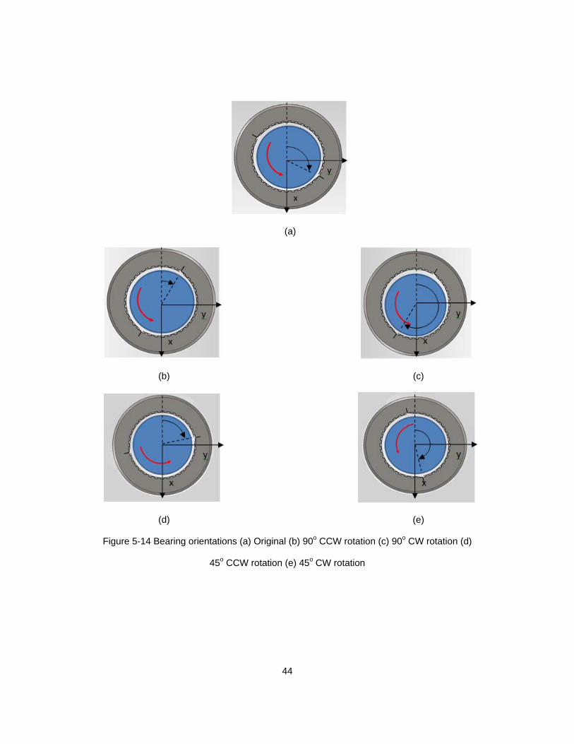
5.5 Effect of Bearing Orientation and Loss Factor
In order to study the effect of change in bearing orientation on the bearing
performance, simulation was performed by clocking the orientation of bearing in different
angles. This was done by varying the pad start angle. Figure 5-14 shows the original
orientation and clocked orientations, which were simulated. All the simulation were
performed with preload of 50 mµ and hot assembly clearance of 63 mµ with structural
damping loss factor η value as 0.134.
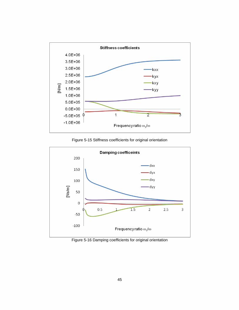
Figure 5-15~Figure 5-16 shows the stiffness and damping coefficient of the
original orientation at 155,000 rpm with frequency ratio ranging from 0.05 to 3. The direct
stiffness and damping coefficients are higher, while all the cross-coupled terms are lower
43
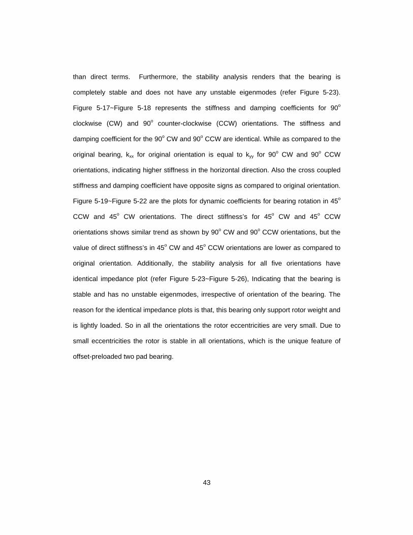
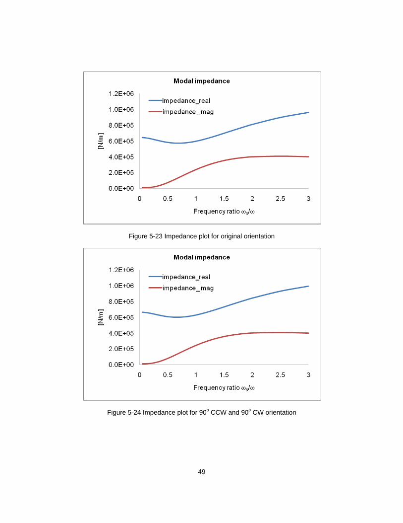
than direct terms. Furthermore, the stability analysis renders that the bearing is
completely stable and does not have any unstable eigenmodes (refer Figure 5-23).
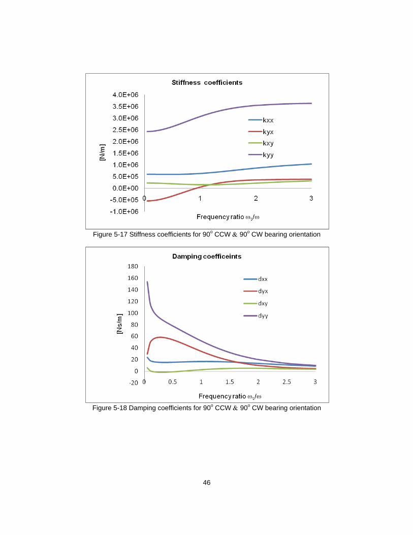
Figure 5-17~Figure 5-18 represents the stiffness and damping coefficients for 90o
clockwise (CW) and 90o counter-clockwise (CCW) orientations. The stiffness and
damping coefficient for the 90o CW and 90o CCW are identical. While as compared to the
original bearing, kxx for original orientation is equal to kyy for 90o CW and 90o CCW
orientations, indicating higher stiffness in the horizontal direction. Also the cross coupled
stiffness and damping coefficient have opposite signs as compared to original orientation.
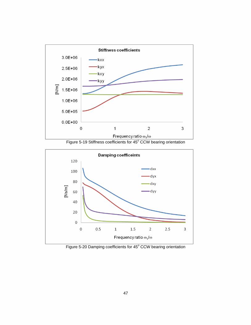
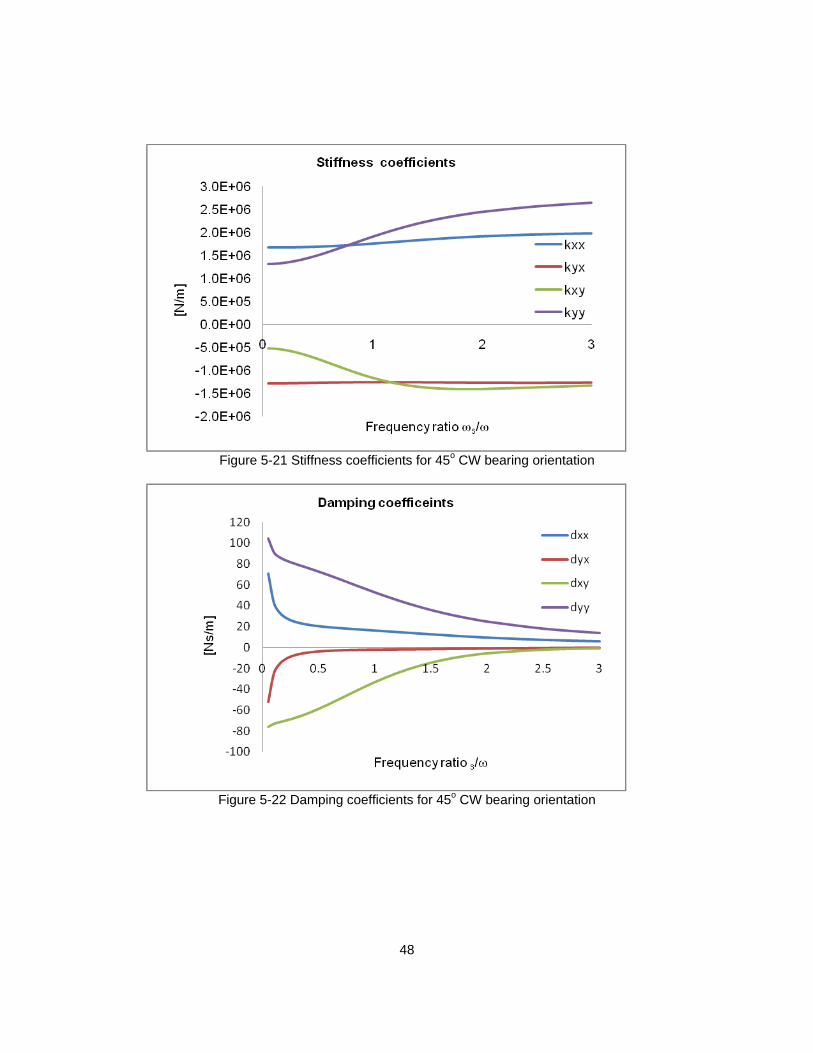
Figure 5-19~Figure 5-22 are the plots for dynamic coefficients for bearing rotation in 45o
CCW and 45o CW orientations. The direct stiffness’s for 45o CW and 45o CCW
orientations shows similar trend as shown by 90o CW and 90o CCW orientations, but the
value of direct stiffness’s in 45o CW and 45o CCW orientations are lower as compared to
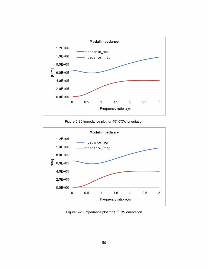
original orientation. Additionally, the stability analysis for all five orientations have
identical impedance plot (refer Figure 5-23~Figure 5-26), Indicating that the bearing is
stable and has no unstable eigenmodes, irrespective of orientation of the bearing. The
reason for the identical impedance plots is that, this bearing only support rotor weight and
is lightly loaded. So in all the orientations the rotor eccentricities are very small. Due to
small eccentricities the rotor is stable in all orientations, which is the unique feature of
offset-preloaded two pad bearing.
44
(a)
(b) (c)
(d) (e)
Figure 5-14 Bearing orientations (a) Original (b) 90o CCW rotation (c) 90o CW rotation (d)
45o CCW rotation (e) 45o CW rotation
45
Figure 5-15 Stiffness coefficients for original orientation
Figure 5-16 Damping coefficients for original orientation
46
Figure 5-17 Stiffness coefficients for 90o CCW & 90o CW bearing orientation
Figure 5-18 Damping coefficients for 90o CCW & 90o CW bearing orientation
47
Figure 5-19 Stiffness coefficients for 45o CCW bearing orientation
Figure 5-20 Damping coefficients for 45o CCW bearing orientation
48
Figure 5-21 Stiffness coefficients for 45o CW bearing orientation
Figure 5-22 Damping coefficients for 45o CW bearing orientation
49
Figure 5-23 Impedance plot for original orientation
Figure 5-24 Impedance plot for 90o CCW and 90o CW orientation
50
Figure 5-25 Impedance plot for 45o CCW orientation
Figure 5-26 Impedance plot for 45o CW orientation
51
Chapter 6
Conclusion and Future Work
6.1 Conclusion
Dynamic performance of the two pad offset-preloaded bearing was evaluated
using the code developed by Dr. Kim. Bump stiffness and structural damping loss factor
was measured using load-deflection test and hysteresis damping energy. Load-deflection
tests were performed on a circular bearing with zero clearance. Hysteresis plot obtained
from load-deflection test was used to determine the structural stiffness and damping loss
factor of the bearing. Using the structural characteristics of the zero clearance bearing,
single bump stiffness formula was derived. The bump stiffness bumpk of the bump foil
was found to be about 8.95e5 N/m. Additionally, area enclosed in hysteresis loop was
used to calculate the damping loss factor, which was about 0.134.
Optimum clearance and preload of the bearing were found. For this purpose, set
of simulations were performed with different combinations of preload and hot assembly
clearance. Experimentally-calculated bump stiffness and structural damping loss factor
were used as input parameters to the simulation. From these simulations it was
evaluated that the bearing with preload around ~ 49 mµ is stable and does not have any
unstable eigenmodes. Based on this, the bearing preload of 50 mµ and hot assembly
clearance of 63 mµ was selected for the bearing.
Using designed preload and clearance, simulations were performed to check the
bearing performance at different clocked orientations with respect to the loading direction.
Along with the original or designed orientation bearing performance was evaluated at 90o
CCW, 90o CW, and 45o CCW and 45o CW orientation. From the simulations it was found
that irrespective of bearing orientation all the direct force coefficients are higher than the
52
cross-coupled force coefficients, indicating stability of the bearing. Furthermore, absence
of eigenmode or negative imaginary impedance confirms the bearing stability. This novel
feature of bearing stability at any orientation indicates that the actual micro gas turbine
can be fitted in any orientation.
6.2 Future Work
This thesis presents the simulation results for force coefficients and stability
analysis of the rotor. Validating the force coefficients by using external excitation source
like magnetic shaker or impact hammer may be included in future work. Along with that
rotordynamic analysis or imbalance response of the rotor may be included in future work.
The scope of this thesis was limited to cylindrical modal analysis due to sponsor
requirement for disclosure of confidential information. Future work may include more
rigorous analysis including conical mode and under various external disturbances
including impeller aerodynamic forces and super-synchronous excitations.
53
Appendix A
Data Acquisition Using Lab View
54
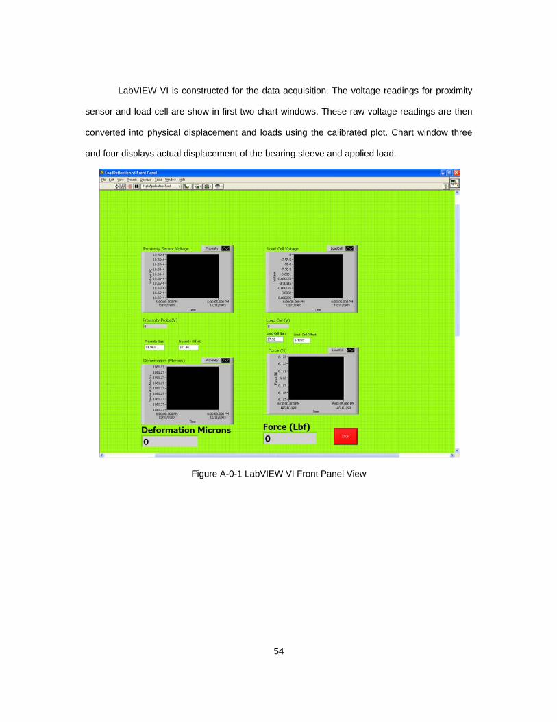
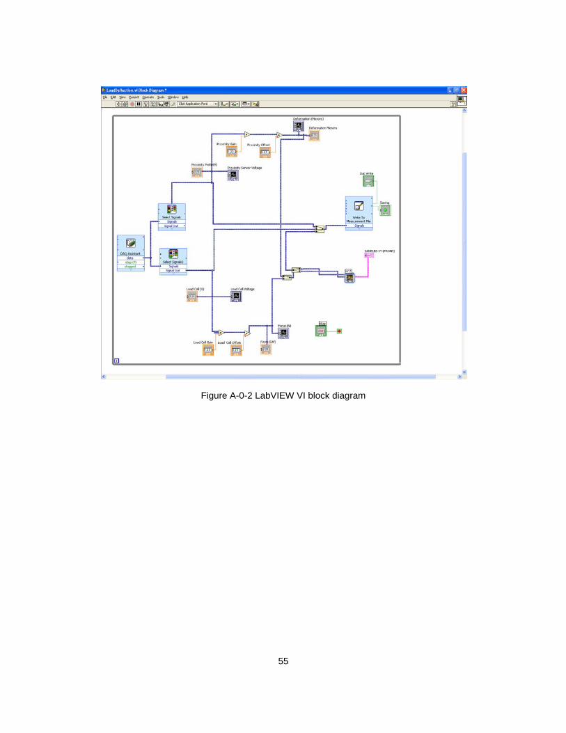
LabVIEW VI is constructed for the data acquisition. The voltage readings for proximity
sensor and load cell are show in first two chart windows. These raw voltage readings are then
converted into physical displacement and loads using the calibrated plot. Chart window three
and four displays actual displacement of the bearing sleeve and applied load.
Figure A-0-1 LabVIEW VI Front Panel View
55
Figure A-0-2 LabVIEW VI block diagram
56
Bibliography
[1] Agrawal, G. L., 1997, "Foil Air/Gas Bearing Technology -- an Overview," International Gas Turbine & Aeroengine Congress & Exhibition, Orlando, FL, June 2-June 5,1997, ASME Paper No. 97-GT-347.
[2] Dykas, B., Bruckner, R., DellaCorte, C., Edmonds, B., and Prahl, J., 2008, "Design, Fabrication, and Performance of Foil Gas Thrust Bearings for Microturbomachinery Applications," ASME Turbo Expo 2008, Berlin, Germany, June 9-13, ASME Paper number GT2008-50377.
[3] Ki, J., Kim, D., and Honavara-Prasad, S., 2012, "Dynamic Modeling of a Compact Heat Exchange Reformer for High TemperatureFuel Cell Systems," Journal of Fuel Cell Science and Technology, 9, pp. 011013-01-16.
[4] Heshmat, H., Walowit, J. A., and Pinkus, O., 1983, "Analysis of Gas Lubricated Compliant Thrust Bearings," ASME Journal of Lubrication Technology, 105(4), pp. 638-646.
[5] DellaCorte, C., and Valco, M. J., 2000, "Load Capacity Estimation of Foil Air Journal Bearings for Oil-Free Turbo-Machinery Applications," STLE Tribology Transaction, 43(4), pp. 795-801.
[6] Iordanoff, I., 1999, "Analysis of an Aerodynamic Compliant Foil Thrust Bearing: Method for a Rapid Design," Journal of Tribology, 121(4), pp. 816-822.
[7] Radil, K., Howard, S., and Dykas, B., 2002, "The Role of Radial Clearance on the Performance of Foil Air Bearings," STLE Tribology Transaction, 45(4), pp. 485-490.
[8] Ku, C. P., and Heshmat, H., 1994, "Structural Stiffness and Coulomb Damping in Compliant Foil Journal Bearing: Parametric Studies," STLE Tribology Transaction, 37(3), pp. 455-462.
[9] Rubio, D., and San Andrés, L., 2006, "Bump-Type Foil Bearing Structural Stiffness: Experiments and Predictions," Journal of Engineering for Gas Turbines and Power, 128(3), pp. 653-660.
[10] Kim, D., 2007, "Parametric Studies on Static and Dynamic Performance of Air Foil Bearings with Different Top Foil Geometries and Bump Stiffness Distributions," ASME Journal of Tribology, 129(2), pp. 354-364.
[11] Song, J., and Kim, D., 2007, "Foil Gas Bearing with Compression Springs: Analyses and Experiments," ASME Journal of Tribology, 129(3), pp. 628-639.
57
[12] Lee, Y., Kim, C. H., Kim, T. H., and Kim, T. Y., 2012, "Effects of Mesh Density on Static Load Performance of Metal Mesh Gas Foil Bearings," Journal of Engineering for Gas Turbines and Power, 134(1), pp. 012502.
[13] Radil, K., and Zeszotek, M., 2004, "An Experimental Investigation into the Temperature Profile of a Compliant Foil Air Bearing," STLE Tribology Transactions, 47(4), pp. 470-479.
[14] Lee, D., and Kim, D., 2010, "Thermo-Hydrodynamic Analyses of Bump Air Foil Bearings with Detailed Thermal Model of Foil Structures and Rotor," ASME Journal of Tribology, 132(2), pp. 021704 (12 pages).
[15] Kim, D., 2012, Foil bearings with multiple pads with controlled assembly clearance, Disclosed to Office of Intellectual Property, University of Texas at Arlington.
58
Biographical Information
Shrikant Ashok Yadav graduated in May 2007 with Bachelors in Mechanical
Engineering from University of Pune. He worked for 3 years as Senior Systems Engineer
in Infosys ltd. India, developing software for 787 support data delivery project. After
working as software engineer he came to UTA in fall 2010 to pursue M.S. in Mechanical
Engineering.