Dynamic fragmentation of an alumina ceramic subjected to...
16
Dynamic fragmentation of an alumina ceramic subjected to shockless spalling: An experimental and numerical study J.L. Zinszner a , B. Erzar b , P. Forquin a,n , E. Buzaud b a Laboratoire Sols Solides Structures-Risques (3SR), Université Grenoble Alpes, BP 53, 38041 Grenoble Cedex 9, France b CEA, DAM, GRAMAT, BP 80200, F-46500 Gramat, France article info Article history: Received 23 April 2015 Received in revised form 20 August 2015 Accepted 25 August 2015 Available online 28 August 2015 Keywords: Spalling Alumina ceramic High-pulsed power DFH damage model Strain-rate sensitivity abstract Ceramic materials are commonly used as protective materials for infantry soldiers and military vehicles. However, during impact, intense fragmentation of the ceramic material is observed. This fragmentation process has to be correctly numerically simulated if one wants to accurately model the dynamic behaviour of the ceramic material during impact. In this work, shockless spalling tests were performed on an alumina ceramic using the high-pulsed power generator (GEPI) equipment. These spalling tests allowed us to master the experimental strain-rate magnitude of the tensile loading applied to the specimen. The spall strength is observed to be rate dependant and the experimental configuration allowed for recovering damaged but unbroken specimen which gives further insights about the fragmentation process initiated in this ceramic material. The collected experi- mental data has been compared with corresponding numerical simulations conducted with the DFH (Denoual–Forquin–Hild) anisotropic damage model. This modelling ap- proach relies on the description of the main basic micromechanisms activated at high loading rates using physical parameters related to the population of defects that produces multiple cracking in the ceramic material at high strain-rates. Very good agreement was observed between numerical simulations and experimental data in terms of free-surface velocity, size and location of the damaged zones along with crack density in these da- maged zones. & 2015 Elsevier Ltd. All rights reserved. 1. Introduction Since the 60s, ceramic materials have been considered to be very interesting materials for use as protective armour systems for infantry soldiers, vehicles, and helicopter seats (Barron et al., 1969). Due to their high hardnesses and com- pressive strengths (reaching several GPas in the case of alumina (Grady, 1998; Gust and Royce, 1971; Rosenberg et al., 1985) or more than 10 GPa in the case of silicon carbides (Bourne et al., 1997; Feng et al., 1998; Forquin et al., 2003a; Vogler et al., 2006)), shattering (Madhu et al., 2005) or erosion of a striking projectile (den Reijer, 1991) is observed during impact. Furthermore, due to their low density, the use of ceramic materials provides an important weight benefit in comparison with monolithic steel plate armours providing the same ballistic efficiency (Roberson, 1995). However, ceramics also exhibit relatively low tensile strengths (compared to their compressive strengths) along with brittle behaviour under both tensile and unconfined compression loading (Forquin et al., 2003a). Thus, an inevitable fragmentation of the ceramic material will Contents lists available at ScienceDirect journal homepage: www.elsevier.com/locate/jmps Journal of the Mechanics and Physics of Solids http://dx.doi.org/10.1016/j.jmps.2015.08.014 0022-5096/& 2015 Elsevier Ltd. All rights reserved. n Corresponding author. Fax: þ33 47 682 7043. E-mail address: [email protected] (P. Forquin). Journal of the Mechanics and Physics of Solids 85 (2015) 112–127
Transcript of Dynamic fragmentation of an alumina ceramic subjected to...

Contents lists available at ScienceDirect
Journal of the Mechanics and Physics of Solids
Journal of the Mechanics and Physics of Solids 85 (2015) 112–127
http://d0022-50
n CorrE-m
journal homepage: www.elsevier.com/locate/jmps
Dynamic fragmentation of an alumina ceramic subjected toshockless spalling: An experimental and numerical study
J.L. Zinszner a, B. Erzar b, P. Forquin a,n, E. Buzaud b
a Laboratoire Sols Solides Structures-Risques (3SR), Université Grenoble Alpes, BP 53, 38041 Grenoble Cedex 9, Franceb CEA, DAM, GRAMAT, BP 80200, F-46500 Gramat, France
a r t i c l e i n f o
Article history:Received 23 April 2015Received in revised form20 August 2015Accepted 25 August 2015Available online 28 August 2015
Keywords:SpallingAlumina ceramicHigh-pulsed powerDFH damage modelStrain-rate sensitivity
x.doi.org/10.1016/j.jmps.2015.08.01496/& 2015 Elsevier Ltd. All rights reserved.
esponding author. Fax: þ33 47 682 7043.ail address: [email protected] (P
a b s t r a c t
Ceramic materials are commonly used as protective materials for infantry soldiers andmilitary vehicles. However, during impact, intense fragmentation of the ceramic materialis observed. This fragmentation process has to be correctly numerically simulated if onewants to accurately model the dynamic behaviour of the ceramic material during impact.In this work, shockless spalling tests were performed on an alumina ceramic using thehigh-pulsed power generator (GEPI) equipment. These spalling tests allowed us to masterthe experimental strain-rate magnitude of the tensile loading applied to the specimen.The spall strength is observed to be rate dependant and the experimental configurationallowed for recovering damaged but unbroken specimen which gives further insightsabout the fragmentation process initiated in this ceramic material. The collected experi-mental data has been compared with corresponding numerical simulations conductedwith the DFH (Denoual–Forquin–Hild) anisotropic damage model. This modelling ap-proach relies on the description of the main basic micromechanisms activated at highloading rates using physical parameters related to the population of defects that producesmultiple cracking in the ceramic material at high strain-rates. Very good agreement wasobserved between numerical simulations and experimental data in terms of free-surfacevelocity, size and location of the damaged zones along with crack density in these da-maged zones.
& 2015 Elsevier Ltd. All rights reserved.
1. Introduction
Since the 60s, ceramic materials have been considered to be very interesting materials for use as protective armoursystems for infantry soldiers, vehicles, and helicopter seats (Barron et al., 1969). Due to their high hardnesses and com-pressive strengths (reaching several GPas in the case of alumina (Grady, 1998; Gust and Royce, 1971; Rosenberg et al., 1985)or more than 10 GPa in the case of silicon carbides (Bourne et al., 1997; Feng et al., 1998; Forquin et al., 2003a; Vogler et al.,2006)), shattering (Madhu et al., 2005) or erosion of a striking projectile (den Reijer, 1991) is observed during impact.Furthermore, due to their low density, the use of ceramic materials provides an important weight benefit in comparisonwith monolithic steel plate armours providing the same ballistic efficiency (Roberson, 1995). However, ceramics also exhibitrelatively low tensile strengths (compared to their compressive strengths) along with brittle behaviour under both tensileand unconfined compression loading (Forquin et al., 2003a). Thus, an inevitable fragmentation of the ceramic material will
. Forquin).
J.L. Zinszner et al. / J. Mech. Phys. Solids 85 (2015) 112–127 113
occur when a projectile hits a ceramic based armour material (Forquin et al., 2003b; Riou et al., 1998; Zinszner et al., 2015).That is why ceramic plates are always backed by ductile plates constructed from metallic materials such as aluminium orcomposite materials (Medvedovski, 2010). Consequently, the tensile behaviour of the ceramic material along with thefragmentation process play an important role in the behaviour of a specific armour configuration under impact, and requireaccurate modelling of this fragmentation process in order to achieve an optimum design for the desired armourconfiguration.
The fragmentation process of ceramics has been extensively studied by means of flyer plate impact experiments. In aspalling test, the interaction of stress waves is used to generate an intense tensile stress and initiate damage leading todynamic fracture. Bless et al. (1986) conducted spalling tests on two alumina ceramics with different mean grain sizes: Al-300 (20 mm) and AD-85 (5 mm). Experimental results indicated that the strength is reduced when the shock level gets closeto the Hugoniot Elastic Limit (HEL) of the sample being tested. However, for low amplitude shock waves, the spalling stressis nearly constant at 400 MPa for Al-300 and 300 MPa for AD-85. Murray et al. (1998) performed spalling experiments onthree different alumina ceramics at shock levels under and above the HEL showing again a decrease of the spall strengthnear and above the HEL. Moreover, the tensile strength of the ceramic grades characterised by similar mean grain sizes (2–4 mm) but different levels of purity and porosity is clearly influenced by the microstructure of these materials. Similar resultshave been described by Cagnoux and Longy (1988) for five alumina ceramics and by Bourne (2001) on alumina ceramicswith purities ranging from 95% to 99%. Although the influence of the shock magnitude has been extensively investigated,the plate impact technique has not permitted studying the sensitivity of ceramic's tensile strength to the strain-rate. Ashockless loading generated by an electromagnetic device may be employed to identify the strain-rate sensitivity of the spallstrength of ceramic materials (Erzar and Buzaud, 2012). In addition, a standard plate impact experiment necessitates the useof a projectile sabot and propulsive gas that strongly affects the possibility in recovering the damaged sample after the testin order to conduct post-test analyses. Generally, the sample is reduced to dust and small fragments after these kinds ofexperiments. This limitation can be also overcome by using a high-pulsed power technology.
For several years, numerical simulations have played an important role in the research world. Combined with theconstant evolution of computer performances, it allows the prediction of the behaviour and fracture of a test specimenwhen subjected to mechanical loading such as impact loading for example. However, the choice of the material model mayhave an adverse effect on the numerical results if the dynamic behaviour of the material is not well captured by theemployed constitutive law. In classical macroscopic models, the behaviour of the ceramic is the same at every integrationpoints and the material is considered as a continuous medium. One of the most popular macroscopic models to simulate thebehaviour of ceramics under dynamic loading is the Johnson–Holmquist model. First proposed in 1992 with the so-calledJH-1 model (Johnson and Holmquist, 1992), it evolved in two other versions, called JH-2 (Johnson and Holmquist, 1994) andJHB (Johnson et al., 2003). Its phenomenological formulation includes some characteristics of the dynamic behaviour ofceramics like a pressure-dependant strength, a growth of damage with the level of plastic strain and an influence of thedamaged state on the strength of the material. The tensile behaviour of ceramics is given by a unique value of the maximumtensile hydrostatic pressure value, which can be obtained by spalling plate impact experiments. However, this value isgenerally calculated as the mean value obtained from several spalling tests and no strain-rate sensitivity of the spall strengthis taken into account. Moreover, the damage value is only based on increments of the plastic deformation and inverseapproaches are needed to determine the parameters of the damage model. Another model for the shock response ofceramics is given by Rajendran and Grove (Rajendran, 1994; Rajendran and Grove, 1996). In their model, damage evolution isbased on the growth of microcracks initiated at flaws initially distributed in the material. Despite the physical description ofthe damage, the numerical parameters have to be determined using an inverse approach as in the case of the Johnson–Holmquist model. Several other damage models are also based on an initial population of defects in the material such asthose used by Hazell and Iremonger (1997), Paliwal and Ramesh (2008), and Keita et al. (2014). However, this last modelneeds a non-zero initial damage value and an inverse approach is still necessary. Fernández-Fdz et al. (2011) have developeda phenomenological model where the tensile damage is based on the maximum principal stress and a parameter related tothe growth rate of the cracks. Despite the ability of existing models to simulate the dynamic behaviour of ceramics, inverseapproaches are often required, and reduces their predictive capabilities. The Denoual–Forquin–Hild (DFH) anisotropic da-mage model (Denoual and Hild, 2000; Forquin and Hild, 2010) aims to alleviate this situation due to the fact that it relies ona description of the main mechanisms activated at the microscale and employs parameters that can be identified fromindependent experiments.
In this work, an experimental technique based on high-pulsed power technologies is employed to conduct spallingexperiments at different strain-rates on an alumina ceramic. In the second section, the alumina ceramic used in this work isdescribed as well as quasi-static ring-on-ring bending tests performed on this alumina ceramic. Next, the spalling testsconducted with the GEPI generator allowed us to perform shockless spalling tests. These tests are detailed with a particularfocus on the strain-rate sensitivity of the dynamic tensile strength. In the last section, the Denoual–Forquin–Hild (DFH)anisotropic damage model is presented. Predictions from the modelling of the spalling tests are given in terms of bothclosed form solution along with numerical simulations. Finally, comparisons are provided between the experimental andnumerical results in terms of free surface velocity signal graphs and damage patterns.

J.L. Zinszner et al. / J. Mech. Phys. Solids 85 (2015) 112–127114
2. Quasi-static failure of alumina
2.1. Alumina composition and main mechanical properties
Alumina ceramics are good candidates for integration into armour systems. The alumina ceramic material used in thiswork is AL23 (Cosculluela, 1992), and has a high purity (99.7%). Very few glassy phases are observed in the microstructure atthe end of the sintering process, mainly MgO, SiO2 and Na2O. The grain size has been estimated in the range 20–70 mm. Itsaverage density has been measured from alumina blocks and plates and found to be approximately ρ0¼3850 kg/m3
(750 kg/m3). Cosculluela (1992) performed plate impact experiments to determine the HEL of this material and obtainedan average value of 6.25 GPa.
2.2. Quasi-static characterisation
When a ceramic material is subjected to a quasi-static tensile load causing failure, a scatter in the failure stresses isobserved. Considering that cracks are initiated at pre-existing defects in the microstructure (such as pores, sintering defects,interfaces between grains…), the failure emanates from a defect when the maximum principal stress s(x) becomes greaterthan its critical stress si(x). When the loading-rate is low, only one crack leads to the complete failure of the specimen.Weibull (1939, 1951) proposes to link the failure stress with an associated cumulative probability of failure PF given by:
P V1 exp , 1F t effλ σ= − [ − ( ) ] ( )
where tλ σ( ) is the density of critical defects at a stress σ and defined by
⎡⎣⎢
⎤⎦⎥ ,
2t
m
00
λ σ λ σσ
( ) =( )
where m is the Weibull modulus, and m0σ /λ0 is the Weibull scale parameter which are both characteristics of the defect
population in the material. The term Veff, given by Davies (1973), defines the effective volume that takes into account thestress heterogeneity in the loaded volume, and is defined by
⎛⎝⎜
⎞⎠⎟V d ,
3eff
max
m
∫ σσ
ω=( )Ω
where the symbol o .4 corresponds to Macaulay brackets (i.e. the positive part of the value).The Weibull scale parameter is related to the mean failure stress and effective volume according to
⎛⎝⎜
⎞⎠⎟V
mm
1,
4w eff m0 01
σ σ λ Γ= ( ) +( )
−
where Γ is the Eulerian function of the second kind that corresponds to an extension of the factorial function with real andcomplex numbers.
In order to characterise the defect population of a brittle material, quasi-static failure tests are generally performed. Inthis study, a series of seventeen quasi-static ring-on-ring bending tests were performed on disc specimens. These specimenshad a diameter of 18 mm and thickness h of 1 mm. The radiuses of the upper and the lower loading rings are equal tob¼5 mm and a¼8 mm. The stress field in the specimen is given as (Timoshenko and Woinowsky-Krieger, 1959):
⎜ ⎟
⎛
⎝⎜⎜
⎞
⎠⎟⎟
⎛
⎝⎜⎜
⎞
⎠⎟⎟⎛⎝
⎞⎠
r zzM r
hM r
Fa ba
r b
Fa ba
r ab a
b r a
,12
with
18
1 ln
4if
18
1 ln
4if
,
5
ff
ba
ba
3
2 2
2
2 2
2
σ
νπ
ν
π
νπ
ν
π
( ) =( )
( ) = {
( − )( − ) −( + ) ( )
≤
( − )( − ) −( + ) ( ) −
−< ≤
( )
where r is the radius, F is the applied force on the supports and z is the axial position along the thickness varying between�h/2 and h/2. Maximum tensile stresses varying from 168.6 to 232.7 MPa were obtained with a mean failure stress of202.8 MPa. The Weibull modulus m, that gives a direct indication on the scatter of failure strength, is equal to 12.8. In
Table 1Weibull parameters of AL23 alumina obtained from quasi-static bending tests.
Strain-rate(s�1)
Weibullmodulus
Mean failurestress (MPa)
Effective volume(mm3)
10�5 12.8 202.8 3.1

Fig. 1. (a) GEPI machine overview, (b) principle of the strip line design and (c) experimental configuration of spalling tests conducted on alumina.
J.L. Zinszner et al. / J. Mech. Phys. Solids 85 (2015) 112–127 115
addition, knowing the stress field in the sample from Eq. (5) and according to Eq. (3), the analytical effective volume in thecase of these ring-on-ring bending tests is
Vh a abm b m b m
m m2 2
2 1 2.
6eff
2 2 2 2
2π= ( + + + )
( + ) ( + ) ( )
All the Weibull parameters obtained from the quasi-static bending tests are provided in Table 1.The 17 bending tests carried out on the alumina ceramic samples allowed us to characterise the defect population
activated in quasi-static tensile loadings. The same material was also tested under dynamic conditions using the GEPImachine.
3. Shockless spalling experiments
3.1. Principle of the spalling test conducted with the GEPI machine
The GEPI machine shown in Fig. 1a is a high-pulsed power machine exploiting the strip line concept (Mangeant et al.,2002) to perform quasi-isentropic experiments or hypervelocity impact by accelerating a flyer plate (Héreil et al., 2004). It isalso used to study the dynamic behaviour of inert materials like composites (Gay et al., 2013) and mortars (Erzar et al., 2013).
The primary energy storage unit consists of 28 stages. The total energy stored reaches 70 kJ from a charging voltage of85 kV. These energy storage unit stages are connected to the load by a strip line. The two electrodes are separated by aninsulator (Mylar and Kapton dielectric foils) as shown in Fig. 1c. Additional peaking capacitors have also been employed tosmooth the temporal current profile and to push away the formation of a shock front when high pressures are generated.Using these peaking capacitors, the released current rises over about 500 ns to a value of 3.3 MA. The current flows to thecentre of the generator so it can be focused in the load region. The current and intense magnetic field generate a com-pressive pulse that is applied to the internal skin of the electrodes. The compressive pulse magσ can be easily assessed fromthe current signal using the relation
⎛⎝⎜
⎞⎠⎟t k
I tW2
,7mag p
02
σμ
( ) = ( )( )
where kp is an edge effect coefficient, 0μ is the magnetic permeability of free space, W is the width of the strip line as shownin Fig. 1b and I t( ) is the current released that is measured by a calibrated Rogowski coil.
The experimental configuration utilised to perform the spalling tests is illustrated in Fig. 1c. The compressive pulse isapplied symmetrically to the internal skin of the electrodes. A reference measurement is done at the electrode/windowinterface. The window sample is constructed from polymethylmetacrylate (PMMA). This signal verifies the chronometry andthe amplitude of the stress wave produced. It can also be useful for determining the wave speed in the ceramic specimen.On the sample side, the velocity profile is measured on the free surface. These two signals are obtained using Fibre DopplerInterferometry (FDI) (Chanal and Luc, 2009). The FDI apparatus is composed of two shifted channels, allowing data pro-cessing by means of sliding Fast Fourier Transform (sFFT) or by using the classical VISAR processing method (Dolan, 2006).The laser spot, with a typical diameter of 20 mm, points at the free surface of the specimen where a thin aluminium layer hasbeen coated with a thickness of a few hundred nano-metres.

Fig. 2. Spalling strength determination from experimental signals, G672 test – W¼70 mm, 16 stages loaded at 70 kV.
J.L. Zinszner et al. / J. Mech. Phys. Solids 85 (2015) 112–127116
3.2. Data processing and experimental results
The FDI signals provide two shifted sets of data for each measurement point and are obtained at the end of each test. Theraw data is then processed one by one using the sFFT. Using the general equation describing the Doppler effect the twoshifted phase signals can be utilised to compute interference patterns (ellipses). With the latter method, the velocity profileis determined by the expression
v tA
f t2
, 80λ
( ) = ( ) ( )
where 0λ corresponds to the laser wavelength (1550 nm), A is a corrective coefficient adapted to the window material (A¼1if the surface is free) and f t( ) is the beat frequency (output of the interferometer).
Two velocity profiles are plotted for each experiment that are given by the signal at the electrode–PMMA interface, andthe free surface velocity of the alumina sample. The first profile constitutes a reference that allows verifying the shape andthe amplitude of the compressive pulse. Because the thicknesses of the electrodes are identical, it is also useful to assess theelastic longitudinal wave speed CL in the alumina specimen by measuring the time differenceΔt between arrivals of releasewaves at the electrode–PMMA interface and at the free-surface of the specimen as illustrated in Fig. 2. For all of the ex-periments reported herein, the loading amplitude stays below the HEL of the alumina ceramic material.
Novikov et al. (1966) introduced a linear acoustic approximation of the spalling stress using the pullback velocityΔUpb asdefined in Fig. 2. The rebound of velocity provides direct evidence of the onset and growth of damage within the core of atested specimen. The rebound velocities provide information about the localisation of the damaged zone. Those reboundvelocities correspond to a wave entrapped in the spall between the damaged zone and the free surface. The distancebetween the damaged zone and the free surface can be roughly estimated from the time between rebounds as shown by thepurple arrows in Fig. 2. Consequently, the velocity profiles provide the necessary information to determine precisely thedynamic tensile strength of alumina ceramic and assess also the distance between the damage plane and the free surface ofthe specimen. Five tests were carried out with electrode widths of 52 and 70 mm to obtain different amplitudes of thecompressive loading (Erzar and Buzaud, 2012). The dataset was completed with an additional spalling experiment, labelledG776, conducted on the same material at a loading level just below the HEL. The configurations and the obtained
Table 2Experimental configurations of spalling tests on alumina.
Electrode widthW (mm)
Number ofstages
Charge ofstages (kV)
Maximum velocity of alu-mina free surface (m/s)
Magnitude of long-itudinal stress (GPa)
Strain-rate atfailure (s�1)
Spall strength(MPa)
G672 70 16 70 30.8 0.612 4900 408G693 52 12 80 40.2 0.794 9000 412G692 52 18 80 67.9 1.35 13,000 453G694 52 22 80 126.5 2.52 20,250 517G695 52 28 80 162.7 3.28 21,500 520G776 35 28 80 290.7 5.90 19,000 410

Fig. 3. Free surface velocity profiles measured on alumina in the 6 spalling experiments (arbitrary origin of time).
J.L. Zinszner et al. / J. Mech. Phys. Solids 85 (2015) 112–127 117
experimental results are summarised in the Table 2. In test G776, conducted with W¼35 mm, the signal increased fasterthan in the other tests. In fact, the thin layer of resin used to glue the specimen on the electrode was partially broken duringthe preparation of the experiment, which leads to a small amplitude shock front (nearly 120 m/s). Nevertheless, it waspossible to analyse this test using loading amplitude close to the HEL of the tested alumina ceramic. All the velocity profilesrecorded on the free surface of the alumina specimens are plotted in Fig. 3.
The strain-rate corresponding to the spalling stress cannot be directly identified from the velocity profiles due to the factthat the strain-rate field varies quickly in space and time during a spalling test conducted using the GEPI generator. Thus, anumerical simulation of the experiment must also be conducted to evaluate the strain-rate at failure. Therefore, a mag-netohydrodynamic (MHD) numerical simulation must first be performed in order to identify and validate the compressiveloading propagating through the electrodes. The current profile is set as input data for the simulation. The electrode–PMMAinterface velocity is obtained numerically, and compared to the interface velocity obtained experimentally. Once the loadingpulse is validated, a numerical simulation is performed considering only elastic behaviour of the ceramic material. Stress andstrain-rate are plotted as functions of time at the location of the damage that is determined using the time interval betweenpost-failure rebounds, as shown in Fig. 2. The “strain-rate at failure” is defined as the value of strain-rate in the calculation atwhich the tensile stress reaches the spalling strength that is determined experimentally.
Fig. 4 presents the determination of the strain-rate at failure in the case of the G672 test. The point at which thelongitudinal stress is plotted is located at 2 mm from the free surface of the specimen. The rapid drop of the strain-rate alongwith the uncertainty of the real position of the damaged zone induce a global uncertainty of 71000 s�1 on the strain-rateat failure.
Fig. 5 provides the results of the 6 experiments conducted on the alumina ceramic. In Fig. 5a, the tensile strengths ofalumina are plotted as a function of strain-rate. These data clearly indicate that the spall strength is sensitive to the loadingrate. While the test conducted at 4900 s�1 indicates a spalling strength of 410 MPa, the strength at 20,000 s�1 reaches about520 MPa (þ26.8%). It is observed that the tensile strength drops of about 110 MPa for the test G776 (W¼35 mm) even witha strain-rate close to 20,000 s�1. For this experiment, the compressive pulse reached more than 95% of the HEL as shown inFig. 5b. Thus, consistently with previous observations made by several other authors of plate impact experiments (Bless
Fig. 4. Determination of the strain-rate at failure: G672 test, sspalling¼410 MPa, ε ̇ ¼4900 s�1.

Fig. 5. Dynamic tensile strength of alumina as a function of (a) the strain-rate and (b) the amplitude of the loading pulse.
J.L. Zinszner et al. / J. Mech. Phys. Solids 85 (2015) 112–127118
et al., 1986; Bourne, 2001; Murray et al., 1998), it is shown that a reduction of the spall strength occurs when the loadingpulse amplitude gets close to the HEL of the alumina ceramic. This phenomenon is certainly linked to the compressivedamage (plasticity and microcracking) initiated below the HEL as reported by Cosculluela (1992) and Longy and Cagnoux(1989) for alumina ceramics.
3.3. Post mortem analyses of a damaged sample
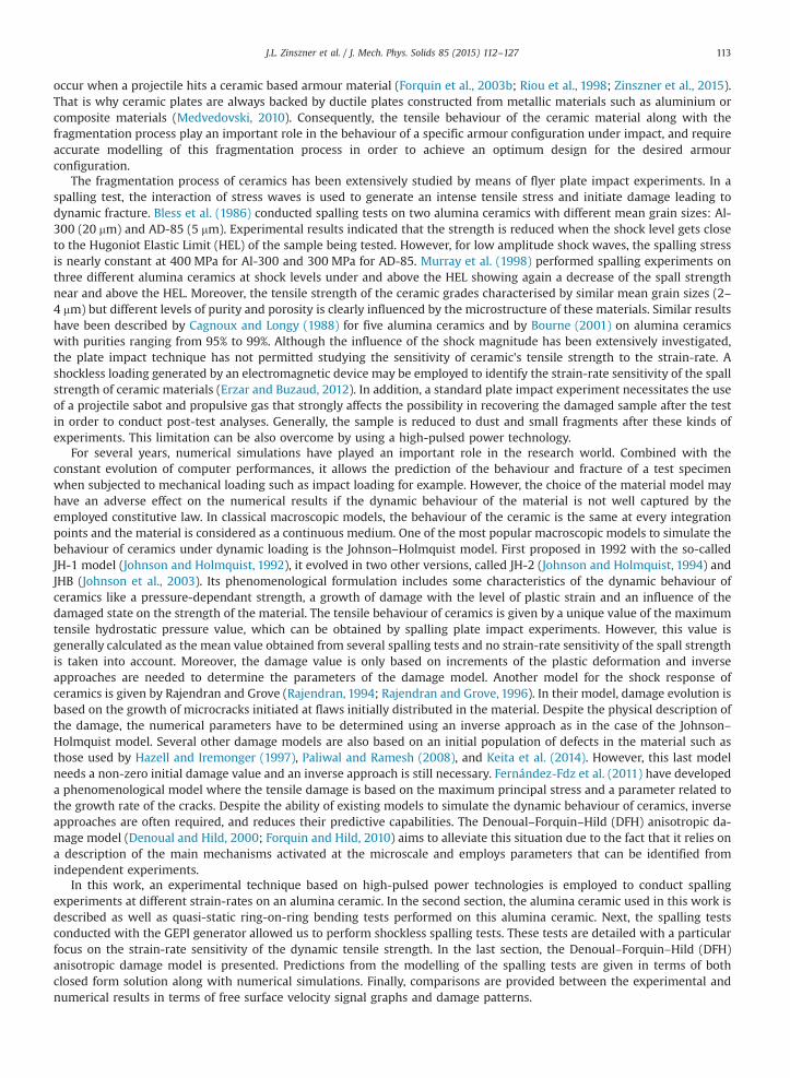
The electromagnetic origin of the loading pulse in GEPI spalling experiments allows making the specimen recovery easiercompared to conventional plate-impact experiments. When a projectile sabot strikes a target, complex recovery systems arerequired for use with plate impact experiments; however no additional systems are necessary with the GEPI generator.Fig. 6 shows post-test states of alumina specimens for three experiments conducted with increasing strain-rates. In theG694 test, the sample is totally fragmented due to the intense release waves coming from the lateral face. In the G693experiment, the amplitude of rarefaction waves was not sufficient to cause total fragmentation of the specimen, and the onlyvisible damage is the spalling fracture plane that cuts the specimen in two pieces. In the test conducted at the lowest strain-rate (G672), the specimen was recovered in one piece without any visible evidence of damage at the macroscopic scale.However, the free-surface velocity signal clearly indicates the initiation of new surfaces in the bulk material and a postmortem analysis has been conducted. For the first time with a brittle material such as the alumina ceramic, a specimen wasrecovered at the spalling limit after a dynamic tensile loading at 4900 s�1. The specimenwas examined by cutting in a planecontaining its axis of revolution.
A new qualitative and quantitative analysis of the damage pattern was applied to the alumina ceramic sample recoveredafter the test G672 performed by Erzar and Buzaud (2012). Fig. 7 provides optical and scanning electron microscopy analysesconducted on the internal face of the damaged sample from this test. Surprisingly, vertical cracks, i.e. parallel to the sampleaxis are observed. These cracks are the result of release waves coming from the lateral free surfaces and crossing each otherin the centre of the circular section of the specimen. However, a careful design of the experiment prevented the pertur-bation of the loading by these rarefaction waves. These cracks were initiated after the spalling planes, which explains thefact that they do not cross the damaged zone which is composed of horizontal cracks (i.e. parallel to the free surface).
The analysis of the damage pattern reveals the initiation and propagation of a multitude of cracks parallel to the rear face
Fig. 6. Post-test state of the electrode and the specimen after experiments: (a) G672, (b) G693, (c) G694.
Fig. 7. Post-test analysis of a specimen at the spalling limit (G672). (a) Optical and (b) scanning electron microscopy images of the inner damage provokedby the tensile loading.
J.L. Zinszner et al. / J. Mech. Phys. Solids 85 (2015) 112–127 119
of the sample. According to numerical simulations of the spalling tests presented in the last section, all these cracks areinitiated due to the spall loading. After the initiation and propagation of the spalling cracks, wave reverberations occur inthe rear part of the sample. However, the amplitude of the reverberations is lower than the spall strength and even lowerthan the first tensile loading; therefore, no additional cracks can be created.
The experimental crack density in the damaged zone was evaluated approximately by considering the mean distancebetween each crack. The vertical cracks are due to release waves coming from the lateral surface, and are initiated after thefragmentation process. Thus, only the horizontal cracks are taken into account in the determination of the crack density.Assuming that most of the cracks are located between the two horizontal blue dashed lines in Fig. 7, the mean distancebetween cracks is calculated based on the number of cracks crossing a vertical line. After repeating this operation thirtytimes, mean distances between cracks in the range of 190–490 μm were obtained, and correspond respectively to crackdensities of 1010 and 1011 cracks/m3.
The quantitative data gathered from the dynamic fragmentation process represent a unique insight into the fragmen-tation process of brittle materials and constitutes original experimental data that is used to validate the micromechanicalmodelling approach.
4. Dynamic fragmentation modelling
4.1. The Denoual–Forquin–Hild (DFH) anisotropic damage model
The quasi-static failure of a brittle material is the result of one or possibly only a few cracks whereas damage produced bya dynamic loading is composed of multiple cracks. The basic assumption of the model is that the defect population is thesame under quasi-static and dynamic loadings. Thus, cracks may be initiated at the same defects independent of the rate ofloading. The Weibull parameters determined by quasi-static bending tests in Section 3 provide useful input data for the DFHmodel. By considering an initial population of defects in the material which is described by its Weibull parameters, cracksare initiated at critical defects when the local microscopic stress reaches the critical stress of each defect. When a crackpropagates, release waves are initiated on the lips of the crack. The release of stresses in the vicinity of the propagating crackprevents the activation of other critical defects located in a zone called “obscuration zone”. This crack shielding process iscalled the defect obscuration phenomenon (Denoual and Hild, 2000; Forquin and Hild, 2010). The size of the obscuredvolume V0 is assumed to grow at the crack velocity vcrack raised to the power n (n being the dimension of the consideredspace) and is given by
V T t S v T t , 9o crackn( − ) = [ ( − )] ( )
where S is a shape parameter (equal to 4π/3 for n¼3, S¼π for n¼2 or S¼2 for n¼1), T is the current time, and t is the crackinception time. The crack velocity is considered to be proportional to the one dimensional elastic wave velocity of thematerial C0(C0¼(E/ρ)1/2 where E is Young's modulus, and ρ is its density) according to
J.L. Zinszner et al. / J. Mech. Phys. Solids 85 (2015) 112–127120
v kC , 10crack 0= ( )
where k is a numerical constant to be determined. Based on an energetic approach of the dynamic propagation of a singlecrack, Broek (1982) and Kanninen and Popelar (1985) have analytically shown that the value k quickly tends to a limit valuek¼0.38. Oberg et al. (2013) have experimentally measured the crack velocity in two alumina ceramics having differentpurities. The experimental values ranged from 0.30C0 to 0.45C0 in the case of pure aluminas and from 0.30C0 to 0.40C0 in thecase of impure aluminas. Thus, the parameter k¼0.38 is employed in the present analysis.
In the case of a multiple fragmentation, the non-obscuration probability for a given point in the loaded volume is givenby Denoual and Hild (2000) and Forquin and Hild (2010) as
Pt
tV T t texp
dd
d . 11no
Tt
00∫ λ
= ( −( )
( − ) ) ( )
Considering that the same defect population is activated under quasi-static and dynamic loading, λt is the density ofcritical defects defined by Eq. (2). The damage variable D is defined from the probability of non-obscuration and may also bewritten as the ratio between the obscured volume and the total volume according to Denoual and Hild (2000) as
D PV
V1 .
12nototal
0= − ≃( )
In the DFH model, the damage is considered as anisotropic and a damage variable is defined for each principal direction.The strain tensor ε is related to the principal stress tensor Σ in the damaged material (also called “macroscopic stress”) by
E
D
D
D
1
11
11
11
.
13
1
2
3
ε
ν ν
ν ν
ν ν
¯̄ = [
−− −
−−
−
− −−
]Σ̄̄
( )
In the case of a multiple fragmentation, the growth of each damage variable Di is defined by
⎛⎝⎜
⎞⎠⎟
d
t DDt
n S kC ttd
11
dd
whendd
0 and 0.14
n
ni
i nt i
ii
1
1 0 λ σσ
σ−
= ! ( ) [ ( )] > >( )
−
−
Considering that new cracks are initiated outside the obscured zones, the rate of crack density is given in Forquin andHild (2010) by
tP
t. 15
cracksno
tλ λ∂∂
=∂∂ ( )
The fragmentation process finishes when all the volume is obscured, Denoual and Hild (2000) have obtained thecharacteristic parameters for the model including the characteristic time tc. This characteristic time corresponds to themoment at which each crack obscures an average volume equal to the total volume divided by the total number of cracksand is given by
⎛⎝⎜
⎞⎠⎟
⎛⎝⎜⎜
⎞⎠⎟⎟t
S v
1.
16c
mn
crack0
1
0 1/
mm n m
m n
nm n
λ σ σ= ̇( )
− + −+
+
Additionally, the damage variable can also be written as a function of the characteristic time tc when a constant stress-rate is assumed as given in Forquin and Hild (2010) by
⎛⎝⎜⎜
⎛⎝⎜
⎞⎠⎟
⎞⎠⎟⎟D
m nm n
Tt
1 exp .17c
m n
= − − ! !( + )! ( )
+
The quasi-totality of the damage process occurs between tc and 2tc (Hild et al., 2003). Thus, the characteristic time givesan indication on the duration of the damage process in the material at a constant stress-rate.
Considering the ultimate stress Σu as the maximal macroscopic stress in the material at which dΣ(t)/dt¼0, then Σu isgiven by
⎛⎝⎜
⎞⎠⎟
⎛⎝⎜
⎞⎠⎟
⎛⎝⎜⎜
⎞⎠⎟⎟
⎛⎝⎜
⎞⎠⎟e
m nm n S v e
m nm n
1 1 1 1,
18u c
mn
crack0
1
0 1/
m nm
m nn
m n m n1 1
σ λ σ σΣ = ( + − )!! !
= ̇ ( + − )!! ! ( )
−+ + + +
where the characteristic stress cσ is defined as cσ ¼ tcσ ̇ From Eq. (18) for the ultimate stress, a comparison of the dynamictensile strength obtained by the spalling test with that given by the model considering the Weibull parameters given in

J.L. Zinszner et al. / J. Mech. Phys. Solids 85 (2015) 112–127 121
Table 1 can be made.
4.2. Numerical implementation of the fragmentation model
Denoual and Hild (2000) have shown that the response of a ceramic material under tensile loading depends on thestrain-rate. For the quasi-static case, the failure is mainly due to a simple crack and the behaviour is probabilistic andgoverned by the Weibull probability distribution. According to Forquin and Hild (2010), in the case of a single fragmentation(low strain-rate), the obscuration probability corresponds to the failure probability expressed by the Weibull distribution.When the strain-rate is sufficiently high, multiple fragmentation occurs, and this phenomenon is characterised by a sig-nificant decrease of the standard deviation of the mean failure stress. This behaviour tends to be deterministic and isgoverned by the DFH model. According to Forquin and Hild (2010), the damage variable is based on the non-obscurationprobability according to Eq. (12).
In order to model single or multiple fragmentation in each finite element, a random critical stress sk is calculated usingthe method provided in (Denoual and Hild, 2002; Forquin and Hild, 2010) as
⎛⎝⎜⎜
⎛⎝⎜
⎞⎠⎟⎞⎠⎟⎟V
Pln
11
,19
k FEk
0 0
m1
σ σ λ=− ( )
where Pk is a random value between 0 and 1. While the stress in an element is less than sk, no damage can occur. When thestress is greater than sk, damage occurs and the number of critical defects in an element depends on the stress according to
VV
0,
max / , 1 ,.
20t FE
k
FEm
k0 0
λσ σ
λ σ σ σ σ= {
≤[ ( ) ] > ( )
Using this method, the anisotropic damage model is able to describe the tensile failure of ceramic materials over a widerange of strain-rates that spans the quasi-static to the high strain-rate regimes. This model was then implemented inAbaqus/explicit through a VUMAT subroutine.
4.3. Parameters adjustment
Using the Weibull probability distribution parameters obtained from quasi-static bending tests in Table 1, the closedform solution of the DFH model given by Eq. (18) (shown by the green dashed line in Fig. 8) underestimates the dynamictensile strength obtained experimentally from GEPI spalling tests. Two reasons may explain this difference. The first reasonis due to a possible strain-rate sensitivity of the alumina’s tensile strength at low strain-rates. According to many authors(Evans, 1974; Fett et al., 1991; Lankford, 1977, 1981; Nejma et al., 2004) an increase of strength can be observed in tension orcompression at strain-rates ranging from 1.10�5 s�1 to several hundreds of s�1 due to the initiation and growth of a sub-critical crack in the alumina ceramic. This phenomenon may explain the possible underestimation of the dynamic tensilestrength when using the Weibull parameters identified at very low strain-rate (as quasi-static ring-on-ring bending testsgiven in Table 1). This conjecture could be validated by performing additional static bending tests at intermediate strain-rates.
Fig. 8. Comparison between the tensile strength predicted by the DFH model considering 2 different Weibull parameter sets obtained from quasi-staticbending tests (green dashed line) and after adjustment (red line) and the experimental results of GEPI spalling tests.

Table 3Physical and mechanical parameters of AL23 alumina as well as the Weibull parameter set obtained after adjustment.
Density (kg/m3) Young modulus (GPa) Poisson ratio Weibull modulus Mean failure stress (MPa) Effective volume (mm3)
AL23 alumina 3890 360 0.22 7.4 202.8 5.4
J.L. Zinszner et al. / J. Mech. Phys. Solids 85 (2015) 112–127122
The second possible reason for the underestimation of the dynamic tensile strength in Eq. (18) may be due to a badestimation of the Weibull modulus. According to Eq. (18), the strain-rate sensitivity of the dynamic strength is directlyrelated to the Weibull modulus. Thus, the Weibull modulus depends on the scatter in the failure stresses; therefore, its valuemay vary significantly from one test series to another and using all seventeen bending tests might have led to an inaccuracyof the Weibull modulus. The uncertainty related to the Weibull modulus being higher than the one related to the meantensile strength, it was proposed to determine a “dynamic Weibull modulus” which would reproduce the strain-rate sen-sitivity observed with GEPI spalling tests with greater accuracy.
According to Fig. 8, by decreasing the Weibull modulus from 12.4 to 7.8 and keeping the mean failure stress obtainedfrom the quasi-static bending tests of 202.8 MPa as given in Table 1 a good reproduction of the experimental dynamictensile strength value is obtained. Here, it is observed that the corrected value of the Weibull modulus is closer to theWeibull modulus obtained for other alumina ceramics. For example, Fett et al. (1991) obtained Weibull moduli ranging from7.5 to 10.4 for three grades of alumina ceramics. Gorjan and Ambrozic (2012) and Ambrozic et al. (2014) have obtained aWeibull modulus m of 9.0 after performing series of 5100 and 10,000 bending tests on a 95% pure alumina ceramic. Thecorrected Weibull parameters as well as the physical and mechanical parameters of AL23 alumina used to perform thenumerical simulations of GEPI spalling tests are provided in Table 3.
4.4. Numerical simulation of GEPI spalling tests
The DFH anisotropic damage model given by Forquin and Hild (2010), Hild et al. (2003) was implemented into the finiteelement code Abaqus/Explicit through a VUMAT subroutine and used to simulate the GEPI spalling tests.
To perform numerical simulations of the GEPI spalling tests, a parallelepiped, 10 mm in height and 2.5 mm in width wasmeshed using C3D8R elements (Abaqus built-in 3D continuum elements (Abaqus 2012)). Symmetry conditions were appliedon both of the internal faces of the parallelepiped shown in Fig. 9. On the two external faces, a zero radial displacement
Fig. 9. Overview of the considered geometry and the boundary conditions used to simulate GEPI spalling tests.

Fig. 10. Loading pulses identified by simulation for 4 spalling tests (arbitrary origin of time).
J.L. Zinszner et al. / J. Mech. Phys. Solids 85 (2015) 112–127 123
boundary condition was applied to ensure a uniaxial strain state during the computation. Additionally, the upper face is freeof stress. The free surface velocity used to compare the experimental and numerical results, is averaged over several nodesof this shown face. The parallelepiped geometry and boundary conditions are shown in the Fig. 9. The pressure pulses actingon the specimen which were previously determined have been applied on the lower face. These simulated pressure pulseamplitudes as a function of time are shown in the Fig. 10 for four spalling experiments. For the simulations, the mesh sizewas set to 0.1 mm. Additionally, in one case, a mesh size of 0.33 mm was employed to evaluate the sensitivity of thenumerical simulations to mesh size.
A comparison was done between the experimental and simulated profiles of the free surface velocities for four of the sixspalling tests. These spalling tests correspond to experiments performed at low, medium, high and very high pressure levels.The applied pressure pulses are plotted in the Fig. 10. The spalling tests G672, G692 and G695 performed at respectively4900, 13,000 and 21,500 s�1 are conducted with an amplitude of compressive pulse much lower than the HEL on thecontrary to the fourth spalling test, G776, characterised by a strain-rate at failure of 19,000 s�1 and a maximum amplitude ofthe compressive pulse about 5.9 GPa, which is close to the HEL of this material. Fig. 11 presents plots of experimental andnumerical free surface velocity profiles along with damage patterns in the finite element mesh for the few spalling testsconsidered.
With the exception of the spalling test performed near the HEL in Fig. 11d, the experimental and numerical free surfacevelocity profiles are very similar in terms of velocity at the first rebound along with its residual velocity. This result de-monstrates the capability of the DFH model to simulate the dynamic fragmentation of alumina ceramics. Using a mesh sizeof 0.33 mm, the difference at the first rebound between the experimental and numerical velocities is about 7% as shown inFig. 11b which illustrates that the course mesh also provides reasonable accuracy.
For the G776 test with a maximum compressive stress close to the HEL, a difference is observed between the pullbackvelocities obtained experimentally and numerically. For a strain-rate at failure of 19,000 s�1, the DFH model predicts atensile strength of 503 MPa whereas a spalling strength of 410 MPa was obtained experimentally. As explained previously, acompressive damage is assumed to be the reason for the loss of tensile strength observed close to the HEL and consequentlyfor the differences between the experimental and numerical free surface velocity signals.
For each of these four cases, the damage fields obtained by the simulations for a mesh size of 0.1 mm are provided inFig. 11. The rebounds observed in the free surface velocity graphs give an indication of the distance between the free surfaceand the first damage plane (in relation to the free surface). The location of this plane is placed on top of the damage fields inFig. 11 with a yellow square. This result allows us to quantify the accuracy of the damage fields obtained from the simu-lations. It is observed that the size of the damaged zone is strongly dependant on the strain-rate. As strain rate is increased,the damaged zone becomes denser and longer. Additionally, when the strain-rate is sufficiently low, the damage zone is nothomogeneous and is composed of only a few damaged planes that are not as dense. It is also observed that the beginnings ofthe damaged zones obtained numerically are consistent with the location of the first cracks in relation to the free surface.
Other comparisons are also possible between the experimental and numerical results. The G672 spalling test, which wasperformed at the lowest strain-rate, resulted in a damaged but unbroken specimen that was recovered. Thus, it is possible tocompare the size (and the location) of the damaged zone and crack density between both experimental and numericalresults.
Fig. 12 provides a comparison between the experimental and simulated failure patterns for the G672 spalling test per-formed at 4900 s�1. It is observed that there is a good agreement in terms of the location and the thickness of the damagedzone for both experiment and simulation. Additionally for this test, the damaged zone is not fully damaged but is composed

Fig. 11. Comparisons between experimental and numerical results given by the DFH model in terms of free surface velocity and damage fields (arbitraryorigin of time), (a) G672, (b) G692, (c) G695, (d) G776. (For interpretation of the references to color in this figure, the reader is referred to the web version ofthis article.)
J.L. Zinszner et al. / J. Mech. Phys. Solids 85 (2015) 112–127124
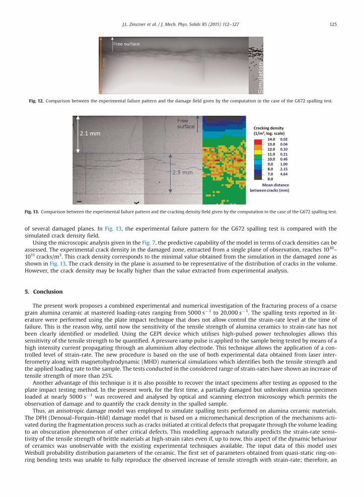
Fig. 12. Comparison between the experimental failure pattern and the damage field given by the computation in the case of the G672 spalling test.
Fig. 13. Comparison between the experimental failure pattern and the cracking density field given by the computation in the case of the G672 spalling test.
J.L. Zinszner et al. / J. Mech. Phys. Solids 85 (2015) 112–127 125
of several damaged planes. In Fig. 13, the experimental failure pattern for the G672 spalling test is compared with thesimulated crack density field.
Using the microscopic analysis given in the Fig. 7, the predictive capability of the model in terms of crack densities can beassessed. The experimental crack density in the damaged zone, extracted from a single plane of observation, reaches 1010–1011 cracks/m3. This crack density corresponds to the minimal value obtained from the simulation in the damaged zone asshown in Fig. 13. The crack density in the plane is assumed to be representative of the distribution of cracks in the volume.However, the crack density may be locally higher than the value extracted from experimental analysis.
5. Conclusion
The present work proposes a combined experimental and numerical investigation of the fracturing process of a coarsegrain alumina ceramic at mastered loading-rates ranging from 5000 s�1 to 20,000 s�1. The spalling tests reported in lit-erature were performed using the plate impact technique that does not allow control the strain-rate level at the time offailure. This is the reason why, until now the sensitivity of the tensile strength of alumina ceramics to strain-rate has notbeen clearly identified or modelled. Using the GEPI device which utilises high-pulsed power technologies allows thissensitivity of the tensile strength to be quantified. A pressure ramp pulse is applied to the sample being tested by means of ahigh intensity current propagating through an aluminium alloy electrode. This technique allows the application of a con-trolled level of strain-rate. The new procedure is based on the use of both experimental data obtained from laser inter-ferometry along with magnetohydrodynamic (MHD) numerical simulations which identifies both the tensile strength andthe applied loading rate to the sample. The tests conducted in the considered range of strain-rates have shown an increase oftensile strength of more than 25%.
Another advantage of this technique is it is also possible to recover the intact specimens after testing as opposed to theplate impact testing method. In the present work, for the first time, a partially damaged but unbroken alumina specimenloaded at nearly 5000 s�1 was recovered and analysed by optical and scanning electron microscopy which permits theobservation of damage and to quantify the crack density in the spalled sample.
Thus, an anisotropic damage model was employed to simulate spalling tests performed on alumina ceramic materials.The DFH (Denoual–Forquin–Hild) damage model that is based on a micromechanical description of the mechanisms acti-vated during the fragmentation process such as cracks initiated at critical defects that propagate through the volume leadingto an obscuration phenomenon of other critical defects. This modelling approach naturally predicts the strain-rate sensi-tivity of the tensile strength of brittle materials at high-strain rates even if, up to now, this aspect of the dynamic behaviourof ceramics was unobservable with the existing experimental techniques available. The input data of this model usesWeibull probability distribution parameters of the ceramic. The first set of parameters obtained from quasi-static ring-on-ring bending tests was unable to fully reproduce the observed increase of tensile strength with strain-rate; therefore, an

J.L. Zinszner et al. / J. Mech. Phys. Solids 85 (2015) 112–127126
adjustment of the Weibull modulus was required. After the modulus adjustment, the numerical simulations performed withthe DFH model implemented in an explicit finite-element code provided very good agreement with the experimental datain terms of free surface velocity profiles, size and location of the damaged zone, and crack density.
In conclusion, this new approach developed by combining experimental results from spalling tests using an innovativehigh-pulsed power device, microscopic analysis of the damaged test specimens along with numerical simulations con-stitutes a new methodology for analysing the fragmentation process induced in ceramics at mastered high loading-rates.
Among the numerous applications of this work it can be employed to better understand the influence of a ceramicmicrostructure on the tensile damage it exhibits. The dynamic fragmentation model was validated over a wide range ofstrain-rates and should provide very accurate simulations for predicting the behaviour of ceramic-based armours subjectedto impacts where dynamic fragmentation is of fundamental importance.
Acknowledgements
This work was supported by DGA (The Armaments Procurement Agency, French Ministry of Defence). The authors arealso grateful to P.-Y. Chanal, J.-J. Royer and P. Rey (CEA GRAMAT) for their technical contribution to this project. The la-boratory 3SR is part of the LabEx Tec 21 (Investissements d’Avenir-grant agreement n°ANR-11-LABX-0030).
References
Abaqus 6.12, 2012. Analysis User's Manual.Ambrozic, M., Gorjan, L., Gomilsek, M., 2014. Bend strength variation of ceramics in serial fabrication. J. Eur. Ceram. Soc. 34, 1873–1879.Barron, E.R., Alesi, A.L., Park, A.F., 1969. In: Body Armor for AircrewmenU.S. Army Natick Laboratories, United States (Technical Report No. 69-43-CE), Natick,
MA.Bless, S., Yaziv, D., Rosenberg, Z., 1986. Spall zones in polycrystalline ceramics. In: Gupta, Y.M. (Ed.), Shock Waves in Condensed Matter. Plenum Press, New
York, NY, pp. 419–424.Bourne, N.K., 2001. The onset of damage in shocked loaded alumina. Proc. R. Soc. Lond. A 457, 2189–2205.Bourne, N., Millet, J., Pickup, I., 1997. Delayed failure in shocked silicon carbide. J. Appl. Phys. 81, 6019–6023.Broek, D., 1982. In: Elementary Engineering Fracture MechanicsMartinus Nijhoff, La Hague, Netherlands.Cagnoux, J., Longy, F., 1988. Spallation and shock-wave behaviour of some ceramics. J. Phys. C3, 3–10.Chanal, P.Y., Luc, J., 2009. Development of fibered velocity interferometers for dynamic material behaviour studies. In: Proceedings of the 60th Meeting of
the Aeroballistic Range Association (ARA), pp. 20–25.Cosculluela, A., 1992. In: Plasticité, Endommagements et Ruptures des Alumines Sous Sollicitations Dynamiques Triaxiales: Influence de la Taille de Grains
(Ph.D. dissertation)Université de Bordeaux I, France.Davies, D.G.S., 1973. The statistical approach to engineering design in ceramics. Proc. Br. Ceram. Soc 22, 429–452.Denoual, C., Hild, F., 2000. A damage model for the dynamic fragmentation of brittle solids. Comput. Methods Appl. Mech. Eng. 183, 247–258.Denoual, C., Hild, F., 2002. Dynamic fragmentation of brittle solids: a multi-scale model. Eur. J. Mech.: A/Solids 21, 105–120.den Reijer P.C., Impact on Ceramic Faced Armour (Ph.D. dissertation), 1991, Delft University of Technology, Netherlands.Dolan, D.H., 2006. In: Foundations of VISAR Analysis Sandia National Laboratories (Sandia Report No. SAND2006-1950), Albuquerque, NM.Erzar, B., Buzaud, E., 2012. Shockless spalling damage of alumina ceramic. Eur. Phys. J.: Spec. Top. 206, 71–77.Erzar, B., Buzaud, E., Chanal, P.Y., 2013. Dynamic tensile fracture of mortar at ultra-high strain-rates. J. Appl. Phys. 114, 244901.Evans, A.G., 1974. Slow crack growth in brittle materials under dynamic loading conditions. Int. J. Fract. 10 (2), 251–259.Feng, R., Raiser, G.R., Gupta, Y.M., 1998. Material strength and inelastic deformation of silicon carbide under shock wave compression. J. Appl. Phys. 83 (1),
79–86.Fernández-Fdz, D., Zaera, R., Fernádez, S.áez, 2011. A constitutive equation for ceramic materials used in lightweight armors. Comput. Struct. 89, 2316–2324.Fett, T., Hartlieb, W., Keller, K., Knecht, B., Munz, D., Rieger, W., 1991. Subcritical crack growth in high-grade alumina. J. Nucl. Mater. 184, 39–46.Forquin, P., Denoual, C., Cottenot, C.E., Hild, F., 2003a. Experiments and modelling of the compressive behaviour of two SiC ceramics. Mech. Mater. 35,
987–1002.Forquin, P., Tran, L., Louvigné, P.-F., Rota, L., Hild, F., 2003b. Effect of aluminum reinforcement on the dynamic fragmentation of SiC ceramics. Int. J. Impact
Eng. 28, 1061–1076.Forquin, P., Hild, F., 2010. A probabilistic damage model of the dynamic fragmentation process in brittle materials. In: Aref, H., van der Giessen, E. (Eds.),
Advances in Applied Mechanics, 44. . Academic Press, San Diego, CA, pp. 1–72.Gay, E., Berthe, L., Buzaud, E., Boustie, M., Arrigoni, M., 2013. Shock adhesion test for composite bonded assembly using a high pulsed power generator. J.
Appl. Phys. 114, 013502.Gorjan, L., Ambrozic, M., 2012. Bend strength of alumina ceramics: a comparison of weibull statistics with other statistics based on very large experimental
data set. J. Eur. Ceram. Soc. 32, 1221–1227.Grady, D.E., 1998. Shock-wave compression of brittle solids. Mech. Mater. 29, 181–203.Gust, W.H., Royce, E.B., 1971. Dynamic yield strengths of B4C, Be0, and Al2O3 ceramics. J. Appl. Phys. 42 (1), 276–295.Hazell, P.J., Iremonger, M.J., 1997. A crack softening damage model for ceramic impact and its application within a hydrocode. J. Appl. Phys. 82, 1088.Héreil, P.L., Lassalle, F., Avrillaud, G., 2004. GEPI: An ICE generator for dynamic material characterization and hypervelocity impact. In: Furnish, M.D., Gupta,
Y.M., Forbes, J.W. (Eds.), AIP Conference Proceeding 706, Shock Compression of Condensed Matter 2003. pp. 1209–1212, Melville, NY.Hild, F., Denoual, C., Forquin, P., Brajer, X., 2003. On the probabilistic-deterministic transition involved in a fragmentation process in brittle materials.
Comput. Struct. 81, 1241–1253.Johnson, G.R., Holmquist, T.J., 1992. A computational constitutive model for brittle materials subjected to large strains, high strain rates, and high pressures.
In: Meyers, M.A., Murr, L.E., Staudhammer, K.P. (Eds.), Shock-wave and High-strain-rate Phenomena in Material, Proceedings of EXPLOMET 901075–1081, Marcel Dekker, Inc., New York, NY.
Johnson G.R. and Holmquist T.J., 1994, An improved computational constitutive model for brittle materials, In: Schmidt S.C., Shaner J.W., Samara G.A.andRoss M., (Eds.), High-Pressure Science and Technology-1993 309, 981, AIP Press, New York, NY.
Johnson, G.R., Holmquist, T.J., Beissel, S.R., 2003. Response of aluminum nitride(including a phase change) to large strains, high strain rates, and highpressures. J. Appl. Phys. 94, 1639.
Kanninen, M.F., Popelar, C.H., 1985. Advanced Fracture Mechanics. Oxford University Press, Oxford, UK.Keita, O., Dascalu, C., François, B., 2014. A two-scale model for dynamic damage evolution. J. Mech. Phys. Solids 64, 170–183.

J.L. Zinszner et al. / J. Mech. Phys. Solids 85 (2015) 112–127 127
Lankford, J., 1977. Compressive strength and microplasticity in polycrystalline alumina. J. Mater. Sci. 12, 791–796.Lankford, J., 1981. Temperature–strain rate dependance of compressive strength and damage mechanisms in aluminium oxide. J. Mater. Sci 16, 1567–1578.Longy, F., Cagnoux, J., 1989. Plasticity and microcracking in shock-loaded alumina. J. Am. Ceram. Soc. 72 (6), 971–979.Madhu, V., Ramanjaneyulu, K., Balakrishna Bhat, T., Gupta, N.K., 2005. An experimental study of penetration resistance of ceramic armour subjected to
projectile impact. Int. J. Impact Eng. 32, 337–350.Mangeant, C., Lassalle, F., L’Eplattenier, P., Héreil, P.L., Bergues, D., Avrillaud, G., 2002. Syrinx project: HPP generators devoted to isentropic compression
experiments. In: Furnish, M.D., Chhabildas, L.C., Hixson, R.S. (Eds.). AIP Conference Proceedings 620, Shock Compression of Condensed Matter 2001, pp.1173–1176, American Institute of Physics, Melville, NY.
Medvedovski, E., 2010. Ballistic performance of armour ceramics: Influence of design and structure. Part I. Ceram. Int. 36, 2103–2115.Murray, N.H., Bourne, N.K., Rosenberg, Z., Field, J.E., 1998. The spall strength of alumina ceramics. J. Appl. Phys. 84 (2), 734–738.Nejma, R., Lang, K.-H., Löhe, D., 2004. Influence of the temperature on the strength and the subcritical crack growth rate of alumina. Mater. Sci. Eng. A 387–
389, 832–836.Novikov, S.A., Divnov, I.I., Ivanov, A.G., 1966. The study of fracture of steel, aluminium and copper under explosive loading. Fizika Metallov I Metallove-
deniye 21, 608–615.Oberg, E.K., Dunleavy, C.S., Bourke, P., Clyne, T.W., 2013. Electrical monitoring of crack propagation during quasi-static loading and ballistic impact of
alumina plates. J. Eur. Ceram. Soc. 33, 2663–2675.Paliwal, B., Ramesh, K.T., 2008. An interacting micro-crack damage model for failure of brittle materials under compression. J. Mech. Phys. Solids 56,
896–923.Rajendran, A.M., 1994. Modeling the impact behavior of AD85 ceramic under multiaxial loading. Int. J. Impact Eng. 15 (6), 749–768.Rajendran, A.M., Grove, D.J., 1996. Modeling the shock response of silicon carbide, boron carbide and titanium diboride. Int. J. Impact Eng. 18 (6), 611–631.Riou, P., Denoual, C., Cottenot, C.E., 1998. Visualization of the damage evolution in impacted silicon carbide ceramics. Int. J. Impact Eng. 21 (4), 225–235.Roberson, C.J., 1995. Ceramic materials and their use in lightweight armour systems. In: Proceedings of the Lightweight Armour System Symposium. Royal
Military College of Science, Cranfield, England.Rosenberg, Z., Yeshurun, Y., Brandon, D.G., 1985. Dynamic response and microstructure of commercial alumina. J. Phys. C5, 331–341.Timoshenko, S., Woinowsky-Krieger, S., 1959. In: Theory of Plates and ShellsMcGraw-Hill, New York, NY.Vogler, T.J., Reinhart, W.D., Chhabildas, L.C., Dandekar, D.P., 2006. Hugoniot and strength behavior of silicon carbide. J. Appl. Phys. 99, 1–15.Weibull, W., 1939. A statistical theory of the strength of materials. In: Proceedings of the Royal Sweden Institute of Engineering Research. Vol. 151.Weibull, W., 1951. A statistical distribution function of wide applicability. ASME J. Appl. Mech., 18; 293–297.Zinszner, J.-L., Forquin, P., Rossiquet, G., 2015. Experimental and numerical analysis of the dynamic fragmentation in a SiC ceramic under impact. Int. J.
Impact Eng. 76, 9–19.
![Identification of a Damage Law by Using Full-Field ... · or crack initiation and/or propagation (Dawicke and Sutton, 1994, Forquin et al., 2004)]; to study an experiment by using](https://static.fdocuments.net/doc/165x107/5c1445ac09d3f25e338b9c84/identification-of-a-damage-law-by-using-full-field-or-crack-initiation-andor.jpg)