DWM1001 FIRMWARE APPLICATION PROGRAMMING INTERFACE (API… Sheets/DecaWave... · DWM1001 FIRMWARE...
69
© Decawave Ltd 2016 Version 0.4 Page 1 of 69 DWM1001 FIRMWARE API GUIDE DWM1001 FIRMWARE APPLICATION PROGRAMMING INTERFACE (API) GUIDE USING API FUNCTIONS TO CONFIGURE AND PROGRAMME DWM1001 MODULE This document is subject to change without notice
Transcript of DWM1001 FIRMWARE APPLICATION PROGRAMMING INTERFACE (API… Sheets/DecaWave... · DWM1001 FIRMWARE...
© Decawave Ltd 2016 Version 0.4 Page 1 of 69
DWM1001 FIRMWARE API GUIDE
DWM1001 FIRMWARE
APPLICATION
PROGRAMMING
INTERFACE (API) GUIDE
USING API FUNCTIONS TO
CONFIGURE AND PROGRAMME
DWM1001 MODULE
This document is subject to change without notice
DW1001 Firmware API Guide
© Decawave Ltd 2016 Version 0.4 Page 2 of 69
DOCUMENT INFORMATION
Disclaimer
Decawave reserves the right to change product specifications without notice. As far as possible changes to
functionality and specifications will be issued in product specific errata sheets or in new versions of this
document. Customers are advised to check the Decawave website for the most recent updates on this
product
Copyright © 2017 Decawave Ltd
LIFE SUPPORT POLICY
Decawave products are not authorized for use in safety-critical applications (such as life support) where a
failure of the Decawave product would reasonably be expected to cause severe personal injury or death.
Decawave customers using or selling Decawave products in such a manner do so entirely at their own risk
and agree to fully indemnify Decawave and its representatives against any damages arising out of the use of
Decawave products in such safety-critical applications.
Caution! ESD sensitive device.
Precaution should be used when handling the device in order to prevent permanent damage
DW1001 Firmware API Guide
© Decawave Ltd 2016 Version 0.4 Page 3 of 69
DISCLAIMER
This Disclaimer applies to the DWM1001 Host Application Programming Interface (API) source code
(“Decawave Software”) provided by Decawave Ltd. (“Decawave”).
Downloading, accepting delivery of or using the Decawave Software indicates your agreement to the
terms of this Disclaimer. If you do not agree with the terms of this Disclaimer do not download, accept
delivery of or use the Decawave Software.
Decawave Software is solely intended to assist you in developing systems that incorporate Decawave
semiconductor products. You understand and agree that you remain responsible for using your
independent analysis, evaluation and judgment in designing your systems and products. THE DECISION
TO USE DECAWAVE SOFTWARE IN WHOLE OR IN PART IN YOUR SYSTEMS AND PRODUCTS RESTS
ENTIRELY WITH YOU.
DECAWAVE SOFTWARE IS PROVIDED "AS IS". DECAWAVE MAKES NO WARRANTIES OR
REPRESENTATIONS WITH REGARD TO THE DECAWAVE SOFTWARE OR USE OF THE DECAWAVE
SOFTWARE, EXPRESS, IMPLIED OR STATUTORY, INCLUDING ACCURACY OR COMPLETENESS.
DECAWAVE DISCLAIMS ANY WARRANTY OF TITLE AND ANY IMPLIED WARRANTIES OF
MERCHANTABILITY, FITNESS FOR A PARTICULAR PURPOSE AND NON-INFRINGEMENT OF ANY THIRD
PARTY INTELLECTUAL PROPERTY RIGHTS WITH REGARD TO DECAWAVE SOFTWARE OR THE USE
THEREOF.
DECAWAVE SHALL NOT BE LIABLE FOR AND SHALL NOT DEFEND OR INDEMNIFY YOU AGAINST ANY
THIRD PARTY INFRINGEMENT CLAIM THAT RELATES TO OR IS BASED ON THE DECAWAVE SOFTWARE
OR THE USE OF THE DECAWAVE SOFTWARE WITH DECAWAVE SEMICONDUCTOR TECHNOLOGY. IN
NO EVENT SHALL DECAWAVE BE LIABLE FOR ANY ACTUAL, SPECIAL, INCIDENTAL, CONSEQUENTIAL OR
INDIRECT DAMAGES, HOWEVER CAUSED, INCLUDING WITHOUT LIMITATION TO THE GENERALITY OF
THE FOREGOING, LOSS OF ANTICIPATED PROFITS, GOODWILL, REPUTATION, BUSINESS RECEIPTS OR
CONTRACTS, COSTS OF PROCUREMENT OF SUBSTITUTE GOODS OR SERVICES; LOSS OF USE, DATA, OR
PROFITS; OR BUSINESS INTERRUPTION), LOSSES OR EXPENSES RESULTING FROM THIRD PARTY
CLAIMS. THESE LIMITATIONS WILL APPLY REGARDLESS OF THE FORM OF ACTION, WHETHER UNDER
STATUTE, IN CONTRACT OR TORT INCLUDING NEGLIGENCE OR ANY OTHER FORM OF ACTION AND
WHETHER OR NOT DECAWAVE HAS BEEN ADVISED OF THE POSSIBILITY OF SUCH DAMAGES, ARISING
IN ANY WAY OUT OF DECAWAVE SOFTWARE OR THE USE OF DECAWAVE SOFTWARE.
You are authorized to use Decawave Software in your end products and to modify the Decawave
Software in the development of your end products. HOWEVER, NO OTHER LICENSE, EXPRESS OR
IMPLIED, BY ESTOPPEL OR OTHERWISE TO ANY OTHER DECAWAVE INTELLECTUAL PROPERTY RIGHT,
AND NO LICENSE TO ANY THIRD PARTY TECHNOLOGY OR INTELLECTUAL PROPERTY RIGHT, IS
GRANTED HEREIN, including but not limited to any patent right, copyright, mask work right, or other
intellectual property right relating to any combination, machine, or process in which Decawave
semiconductor products or Decawave Software are used.
DW1001 Firmware API Guide
© Decawave Ltd 2016 Version 0.4 Page 4 of 69
You acknowledge and agree that you are solely responsible for compliance with all legal, regulatory
and safety-related requirements concerning your products, and any use of Decawave Software in your
applications, notwithstanding any applications-related information or support that may be provided
by Decawave.
Decawave reserves the right to make corrections, enhancements, improvements and other changes
to its software at any time.
Mailing address: -
Decawave Ltd.,
Adelaide Chambers,
Peter Street,
Dublin 8
Copyright (c) 11/08/2017 by Decawave Limited. All rights reserved.
DW1001 Firmware API Guide
© Decawave Ltd 2016 Version 0.4 Page 5 of 69
TABLE OF CONTENTS
1 INTRODUCTION AND OVERVIEW ........................................................................................................... 10
1.1 DWM1001 MODULE AND THE FIRMWARE ................................................................................................... 10
1.2 API AND ITS GUIDE ................................................................................................................................... 10
2 GENERAL API DESCRIPTIONS ................................................................................................................. 11
2.1 TLV FORMAT........................................................................................................................................... 11
2.1 DWM1001 THREADS .............................................................................................................................. 11
2.2 API VIA BLE INTERFACE ............................................................................................................................. 11
2.3 API VIA SPI INTERFACE ............................................................................................................................. 12
2.3.1 DWM1001 SPI overview .................................................................................................................. 12
2.3.2 SPI Scheme: normal TLV communication ........................................................................................ 14
2.3.3 SPI Example: normal TLV communication - dwm_gpio_cfg_output .............................................. 15
2.3.4 SPI Scheme: TLV communication using data ready pin ................................................................... 16
2.3.5 SPI error recovery mechanism ........................................................................................................ 17
2.4 API VIA UART INTERFACE ......................................................................................................................... 18
2.4.1 DWM1001 UART overview.............................................................................................................. 18
2.4.2 UART TLV Mode .............................................................................................................................. 18
2.4.3 UART scheme: TLV mode communication ...................................................................................... 19
2.4.4 UART example: TLV mode communication ..................................................................................... 20
2.4.5 UART scheme: Shell mode communication ..................................................................................... 20
2.4.6 UART example: Shell Mode communication ................................................................................... 21
2.5 GPIO SCHEME: DWM1001 NOTIFIES FOR STATUS CHANGE ............................................................................ 21
2.6 API FOR ON-BOARD C CODE DEVELOPERS ..................................................................................................... 22
3 GENERIC API INFORMATION .................................................................................................................. 23
3.1 USED TERMINOLOGY ................................................................................................................................. 23
3.2 LITTLE ENDIAN ......................................................................................................................................... 23
3.3 FREQUENTLY USED TLV VALUES .................................................................................................................. 23
3.3.1 err_code .......................................................................................................................................... 23
3.3.2 position ........................................................................................................................................... 23
3.3.3 gpio_idx .......................................................................................................................................... 23
3.3.4 gpio_value ...................................................................................................................................... 24
3.3.5 gpio_pull ......................................................................................................................................... 24
3.3.6 fw_version ....................................................................................................................................... 24
3.3.7 cfg_tag ............................................................................................................................................ 24
3.3.8 cfg_anchor ...................................................................................................................................... 25
3.3.9 cfg_node ......................................................................................................................................... 25
4 API FUNCTION DESCRIPTIONS ............................................................................................................... 26
4.1 DWM_POS_SET ....................................................................................................................................... 27
4.1.1 Generic description ......................................................................................................................... 27
4.1.2 C code .............................................................................................................................................. 27
4.1.3 SPI/UART Generic ............................................................................................................................ 27
4.2 DWM_POS_GET ....................................................................................................................................... 28
4.2.1 Generic description ......................................................................................................................... 28
4.2.2 C code .............................................................................................................................................. 28
4.2.3 SPI/UART Generic ............................................................................................................................ 28
DW1001 Firmware API Guide
© Decawave Ltd 2016 Version 0.4 Page 6 of 69
4.3 DWM_UPD_RATE_SET .............................................................................................................................. 29
4.3.1 Generic description ......................................................................................................................... 29
4.3.2 C code .............................................................................................................................................. 29
4.3.3 SPI/UART Generic ............................................................................................................................ 29
4.4 DWM_UPD_RATE_GET .............................................................................................................................. 30
4.4.1 Generic description ......................................................................................................................... 30
4.4.2 C code .............................................................................................................................................. 30
4.4.3 SPI/UART Generic ............................................................................................................................ 30
4.5 DWM_CFG_TAG_SET ................................................................................................................................ 31
4.5.1 Generic description ......................................................................................................................... 31
4.5.2 C code .............................................................................................................................................. 31
4.5.3 SPI/UART Generic ............................................................................................................................ 31
4.6 DWM_CFG_ANCHOR_SET .......................................................................................................................... 32
4.6.1 Generic description ......................................................................................................................... 32
4.6.2 C code .............................................................................................................................................. 32
4.6.3 SPI/UART Generic ............................................................................................................................ 32
4.7 DWM_CFG_GET ....................................................................................................................................... 33
4.7.1 Generic description ......................................................................................................................... 33
4.7.2 C code .............................................................................................................................................. 33
4.7.3 SPI/UART Generic ............................................................................................................................ 33
4.8 DWM_SLEEP ........................................................................................................................................... 34
4.8.1 Generic description ......................................................................................................................... 34
4.8.2 C code .............................................................................................................................................. 34
4.8.3 SPI/UART Generic ............................................................................................................................ 34
4.9 DWM_LOC_GET ....................................................................................................................................... 35
4.9.1 Generic description ......................................................................................................................... 35
4.9.2 C code .............................................................................................................................................. 35
4.9.3 SPI/UART Generic ............................................................................................................................ 36
4.10 DWM_BADDR_SET ................................................................................................................................... 37
4.10.1 Generic description ..................................................................................................................... 37
4.10.2 C code ......................................................................................................................................... 37
4.10.3 SPI/UART Generic ....................................................................................................................... 37
4.11 DWM_BADDR_GET ................................................................................................................................... 38
4.11.1 Generic description ..................................................................................................................... 38
4.11.2 C code ......................................................................................................................................... 38
4.11.3 SPI/UART Generic ....................................................................................................................... 38
4.12 DWM_RESET ........................................................................................................................................... 39
4.12.1 Generic description ..................................................................................................................... 39
4.12.2 C code ......................................................................................................................................... 39
4.12.3 SPI/UART Generic ....................................................................................................................... 39
4.13 DWM_FW_VER_GET ................................................................................................................................. 40
4.13.1 Generic description ..................................................................................................................... 40
4.13.2 C code ......................................................................................................................................... 40
4.13.3 SPI/UART Generic ....................................................................................................................... 40
4.14 DWM_GPIO_CFG_OUTPUT ........................................................................................................................ 41
4.14.1 Generic description ..................................................................................................................... 41
4.14.2 C code ......................................................................................................................................... 41
4.14.3 SPI/UART Generic ....................................................................................................................... 41
4.15 DWM_GPIO_CFG_INPUT ........................................................................................................................... 42
DW1001 Firmware API Guide
© Decawave Ltd 2016 Version 0.4 Page 7 of 69
4.15.1 Generic description ..................................................................................................................... 42
4.15.2 C code ......................................................................................................................................... 42
4.15.3 SPI/UART Generic ....................................................................................................................... 42
4.16 DWM_GPIO_VALUE_SET ........................................................................................................................... 43
4.16.1 Generic description ..................................................................................................................... 43
4.16.2 C code ......................................................................................................................................... 43
4.16.3 SPI/UART Generic ....................................................................................................................... 43
4.17 DWM_GPIO_VALUE_GET ........................................................................................................................... 44
4.17.1 Generic description ..................................................................................................................... 44
4.17.2 C code ......................................................................................................................................... 44
4.17.3 SPI/UART Generic ....................................................................................................................... 44
4.18 DWM_GPIO_VALUE_TOGGLE ..................................................................................................................... 45
4.18.1 Generic description ..................................................................................................................... 45
4.18.2 C code ......................................................................................................................................... 45
4.18.3 SPI/UART Generic ....................................................................................................................... 45
4.19 DWM_STATUS_GET .................................................................................................................................. 46
4.19.1 Generic description ..................................................................................................................... 46
4.19.2 C code ......................................................................................................................................... 46
4.19.3 SPI/UART Generic ....................................................................................................................... 46
4.20 DWM_INT_CFG ....................................................................................................................................... 47
4.20.1 Generic description ..................................................................................................................... 47
4.20.2 C code ......................................................................................................................................... 47
4.20.3 SPI/UART Generic ....................................................................................................................... 47
4.21 DWM_GPIO_IRQ_CFG ............................................................................................................................... 48
4.21.1 Generic description ..................................................................................................................... 48
4.21.2 C code ......................................................................................................................................... 48
4.21.3 SPI/UART Generic ....................................................................................................................... 48
4.22 DWM_GPIO_IRQ_DIS ................................................................................................................................ 49
4.22.1 Generic description ..................................................................................................................... 49
4.22.2 C code ......................................................................................................................................... 49
4.22.3 SPI/UART Generic ....................................................................................................................... 49
4.23 DWM_I2C_READ ..................................................................................................................................... 50
4.23.1 Generic description ..................................................................................................................... 50
4.23.2 C code ......................................................................................................................................... 50
4.23.3 SPI/UART Generic ....................................................................................................................... 50
4.24 DWM_I2C_WRITE .................................................................................................................................... 51
4.24.1 Generic description ..................................................................................................................... 51
4.24.2 C code ......................................................................................................................................... 51
4.24.3 SPI/UART Generic ....................................................................................................................... 51
4.25 DWM_EVT_CB_REGISTER .......................................................................................................................... 52
4.25.1 Generic description ..................................................................................................................... 52
4.25.2 C code ......................................................................................................................................... 52
4.25.3 SPI/UART Generic ....................................................................................................................... 53
5 SHELL COMMANDS ................................................................................................................................ 54
5.1 ? ........................................................................................................................................................... 54
5.2 HELP ...................................................................................................................................................... 55
5.3 QUIT ...................................................................................................................................................... 55
5.4 GC ......................................................................................................................................................... 55
DW1001 Firmware API Guide
© Decawave Ltd 2016 Version 0.4 Page 8 of 69
5.5 GG ........................................................................................................................................................ 55
5.6 GS ......................................................................................................................................................... 56
5.7 GT ......................................................................................................................................................... 56
5.8 F ........................................................................................................................................................... 56
5.9 PS ......................................................................................................................................................... 56
5.10 PMS ....................................................................................................................................................... 57
5.11 RESET ..................................................................................................................................................... 57
5.12 UT ......................................................................................................................................................... 57
5.13 TWI ....................................................................................................................................................... 57
5.14 AID ........................................................................................................................................................ 57
5.15 AV ......................................................................................................................................................... 58
5.16 LES ........................................................................................................................................................ 58
5.17 LEC ........................................................................................................................................................ 58
5.18 LEP ........................................................................................................................................................ 58
5.19 SI .......................................................................................................................................................... 58
5.20 NMG ...................................................................................................................................................... 59
5.21 NMO ...................................................................................................................................................... 59
5.22 NMP ...................................................................................................................................................... 60
5.23 NMA ...................................................................................................................................................... 60
5.24 NMI ....................................................................................................................................................... 61
5.25 NMT ...................................................................................................................................................... 61
5.26 NMTL ..................................................................................................................................................... 61
5.27 LA ......................................................................................................................................................... 62
5.28 STG ....................................................................................................................................................... 62
5.29 STC ........................................................................................................................................................ 63
5.30 TLV ........................................................................................................................................................ 64
5.31 AURS ..................................................................................................................................................... 64
5.32 AURG ..................................................................................................................................................... 64
5.33 APG ....................................................................................................................................................... 64
5.34 APS........................................................................................................................................................ 64
5.35 ACAS ...................................................................................................................................................... 65
5.36 ACTS ...................................................................................................................................................... 65
6 APPENDIX A – TLV TYPE LIST .................................................................................................................. 66
7 APPENDIX B – BIBLIOGRAPHY ................................................................................................................ 67
DOCUMENT HISTORY ..................................................................................................................................... 68
8 ABOUT DECAWAVE ............................................................................................................................... 69
DW1001 Firmware API Guide
© Decawave Ltd 2016 Version 0.4 Page 9 of 69
List of Tables
TABLE 1 TLV FORMAT DATA EXAMPLE ........................................................................................................................... 11
TABLE 2 API REQUEST FUNCTION LIST ............................................................................................................................ 26
TABLE 3 DWM1001 TLV TYPE LIST ............................................................................................................................. 66
TABLE 4: DOCUMENT HISTORY ..................................................................................................................................... 68
List of Figures
FIGURE 1 DWM1001 SPI WORK FLOW ........................................................................................................................ 12
FIGURE 2 SPI SCHEME: NORMAL TLV COMMUNICATION ................................................................................................... 14
FIGURE 3 SPI EXAMPLE: NORMAL TLV COMMUNICATION .................................................................................................. 15
FIGURE 4 SPI SCHEME: TLV COMMUNICATION USING DATA READY PIN ................................................................................ 16
FIGURE 5 DWM1001 UART WORK FLOW .................................................................................................................... 18
FIGURE 6 UART SCHEME: TLV MODE COMMUNICATION .................................................................................................. 19
FIGURE 7 UART EXAMPLE: TLV MODE COMMUNICATION ................................................................................................. 20
FIGURE 8 UART SCHEME: SHELL MODE COMMUNICATION ................................................................................................ 21
FIGURE 9 UART EXAMPLE: SHELL MODE COMMUNICATION ............................................................................................... 21
FIGURE 10 GPIO SCHEME: DWM1001 NOTIFIES HOST DEVICE OF STATUS CHANGE, USING GPIO............................................ 22
DW1001 Firmware API Guide
© Decawave Ltd 2016 Version 0.4 Page 10 of 69
1 INTRODUCTION AND OVERVIEW
1.1 DWM1001 module and the firmware
The DWM1001 module is a radio transceiver module integrating the nRF52 MCU and the DW1000
IC. The nRF52 MCU, which has Bluetooth v4.2 protocol stack implemented [1], is acting as the main
processor of the DWM1001 module. The DW1000 IC part, which has the UWB physical layer defined
in IEEE 802.15.4-2011 standard [2], is acting as the UWB radio module controlled by the nRF52 MCU.
Decawave provides a pre-built firmware library, the “Positioning and Networking stack” (PANS) library,
on the DWM1001 module which operates on the nRF52 MCU. The firmware provides the Application
Programming Interface (API) for users to use their own host devices to communicate with the
DWM1001 module, namely the PANS API. The PANS API essentially is a set of functions providing a
means to communicate with the nRF52 MCU to drive the module through the PANS library on
application level without having to deal with the details of accessing the DW1000 IC part and other
peripherals directly through its SPI/I2C interface register set. The detailed information of the firmware
is introduced in the DWM1001 Firmware User Guide [3].
1.2 API and its guide
The PANS APIs are a set of functions. Each individual API function may be accessed through various
communication interfaces providing flexibility to developers in using the DWM1001 module and
integrating it into their systems. The API accesses mainly come in as two types:
1) External access API: via UART, SPI and BLE.
2) Integrated access API: via on-board user app (C code).
The detailed introduction to the flow with examples of how the API can be used is introduced in [3].
This document, “DWM1001 Device API Guide”, specifies the PANS API functions themselves,
providing descriptions of each of the API functions in detail in terms of its parameters, functionality
and utility. Users can use the PANS API to configure each individual DWM1001 module. To setup a
location system with multiple DWM1001 modules, users should refer to the DWM1001 System
Guide [4].
This document relates to: "DWM1001 PANS Library Version xx.xx"
The DWM1001 firmware version information may be found in source file “xxxx.h”.
DW1001 Firmware API Guide
© Decawave Ltd 2016 Version 0.4 Page 11 of 69
2 GENERAL API DESCRIPTIONS
2.1 TLV format
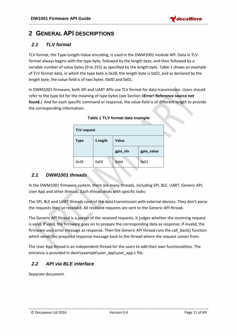
TLV format, the Type-Length-Value encoding, is used in the DWM1001 module API. Data in TLV
format always begins with the type byte, followed by the length byte, and then followed by a
variable number of value bytes [0 to 255] as specified by the length byte. Table 1 shows an example
of TLV format data, in which the type byte is 0x28, the length byte is 0x02, and as declared by the
length byte, the value field is of two bytes: 0x0D and 0x01.
In DWM1001 firmware, both SPI and UART APIs use TLV format for data transmission. Users should
refer to the type list for the meaning of type bytes (see Section 4Error! Reference source not
found.). And for each specific command or response, the value field is of different length to provide
the corresponding information.
Table 1 TLV format data example
TLV request
Type Length Value
gpio_idx gpio_value
0x28 0x02 0x0d 0x01
2.1 DWM1001 threads
In the DWM1001 firmware system, there are many threads, including SPI, BLE, UART, Generic API,
User App and other threads. Each thread deals with specific tasks:
The SPI, BLE and UART threads control the data transmission with external devices. They don’t parse
the requests they’ve received. All received requests are sent to the Generic API thread.
The Generic API thread is a parser of the received requests. It judges whether the incoming request
is valid. If valid, the firmware goes on to prepare the corresponding data as response; if invalid, the
firmware uses error message as response. Then the Generic API thread runs the call_back() function
which sends the prepared response message back to the thread where the request comes from.
The User App thread is an independent thread for the users to add their own functionalities. The
entrance is provided in dwm\example\user_app\user_app.c file.
2.2 API via BLE interface
Separate document.
DW1001 Firmware API Guide
© Decawave Ltd 2016 Version 0.4 Page 12 of 69
2.3 API via SPI interface
2.3.1 DWM1001 SPI overview
DWM1001 SPI interface uses TLV format data. Users can use an external host device in SPI master
mode to connect to the DWM1001 module SPI interface which operates in slave mode. The
maximum SPI clock frequency is 8 MHz.
In the DWM1001 SPI schemes, host device communicates with the DWM1001 through TLV requests.
A full TLV request communication flow includes the following steps:
1) Host device sends TLV request;
2) DWM1001 prepares response;
3) Host device reads the length of total response;
4) Host device reads data response;
Because SPI uses full duplex communication, when the host device (as the SPI master) writes x bytes,
it actually sends x bytes to the DWM1001 module (as the slave), and receives x bytes dummy in the
same time. Similarly for reading, the host device sends x bytes of dummy, and receives x bytes data
back as response. In the DWM1001 SPI scheme, the dummy bytes are octets of value 0xFF.
Read DATA/ERR
ReceivedTLV request
API: Idle
TLV request
TLV valid?
Prepare SIZE & DATA
Prepare SIZE & ERR
call_back()
No
Yes
Init SPI as Slave
SPI:Idle
SPI: Wait forcall_back()
SPI: Wait forRead SIZE
SPI: Wait forRead DATA/ERR
Receive any byte
Generic API threadSPI thread
Read SIZE
User activitySystem activitySystem status
call_back()
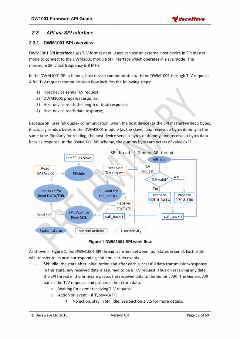
Figure 1 DWM1001 SPI work flow
As shown in Figure 1, the DWM1001 SPI thread transfers between four states in serial. Each state
will transfer to its next corresponding state on certain events.
- SPI: Idle: the state after initialization and after each successful data transmission/response.
In this state, any received data is assumed to be a TLV request. Thus on receiving any data,
the SPI thread in the firmware passes the received data to the Generic API. The Generic API
parses the TLV requests and prepares the return data.
o Waiting for event: receiving TLV requests.
o Action on event – if Type==0xFF:
No action, stay in SPI: Idle. See Section 2.3.5 for more details.
DW1001 Firmware API Guide
© Decawave Ltd 2016 Version 0.4 Page 13 of 69
o Action on event – if Type≠0xFF :
Send received TLV request to Generic API thread.
Transfer to “SPI: Wait for call_back”.
- SPI: Wait for call_back: the DWM1001 SPI is waiting for the Generic API to parse the TLV
request and prepare the response. Any data from the host side will be ignored and returned
with 0x00 in this state.
o Waiting for event: call_back() function being called by the Generic API.
o Action on event:
Toggle data ready pin HIGH – detailed in Section 2.3.4.
Transfer to “SPI: Wait for READ SIZE”.
- SPI: Wait for Read SIZE: the DWM1001 SPI has prepared the SIZE byte as response, which is
only one byte non-zero data indicating the size of data or error message to be responded,
and is waiting for the host device to read the SIZE byte.
o Waiting for event: host device reads one byte.
o Action on event:
Respond with the SIZE byte.
Transfer to “SPI: Wait for READ DATA/ERR”.
- SPI: Wait for Read DATA/ERR: the DWM1001 SPI has prepared SIZE bytes of data or error
message as response to the TLV request, and is waiting for the host device to read it.
o Waiting for event: host device reads any number of bytes.
o Action on event:
Respond with DATA/ERR.
Toggle data ready pin LOW – detailed in Section 2.3.4.
Transfer to “SPI: Idle”.
In DWM1001, starting from “SPI: Idle”, traversing all four states listed above and returning to “SPI:
Idle” indicates a full TLV request communication flow. The user should have received the response
data or error message by the end of the communication flow.
A few different usages and examples are illustrated in the following sub-sections.
DW1001 Firmware API Guide
© Decawave Ltd 2016 Version 0.4 Page 14 of 69
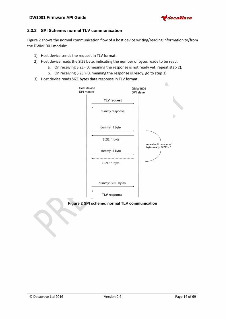
2.3.2 SPI Scheme: normal TLV communication
Figure 2 shows the normal communication flow of a host device writing/reading information to/from
the DWM1001 module:
1) Host device sends the request in TLV format.
2) Host device reads the SIZE byte, indicating the number of bytes ready to be read.
a. On receiving SIZE= 0, meaning the response is not ready yet, repeat step 2).
b. On receiving SIZE > 0, meaning the response is ready, go to step 3)
3) Host device reads SIZE bytes data response in TLV format.
Figure 2 SPI scheme: normal TLV communication
DW1001 Firmware API Guide
© Decawave Ltd 2016 Version 0.4 Page 15 of 69
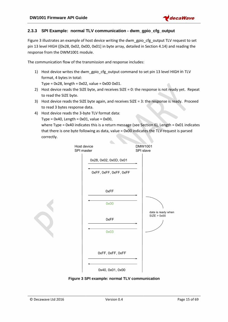
2.3.3 SPI Example: normal TLV communication - dwm_gpio_cfg_output
Figure 3 illustrates an example of host device writing the dwm_gpio_cfg_output TLV request to set
pin 13 level HIGH ([0x28, 0x02, 0x0D, 0x01] in byte array, detailed in Section 4.14) and reading the
response from the DWM1001 module.
The communication flow of the transmission and response includes:
1) Host device writes the dwm_gpio_cfg_output command to set pin 13 level HIGH in TLV
format, 4 bytes in total:
Type = 0x28, length = 0x02, value = 0x0D 0x01.
2) Host device reads the SIZE byte, and receives SIZE = 0: the response is not ready yet. Repeat
to read the SIZE byte.
3) Host device reads the SIZE byte again, and receives SIZE = 3: the response is ready. Proceed
to read 3 bytes response data.
4) Host device reads the 3-byte TLV format data:
Type = 0x40, Length = 0x01, value = 0x00,
where Type = 0x40 indicates this is a return message (see Section 6), Length = 0x01 indicates
that there is one byte following as data, value = 0x00 indicates the TLV request is parsed
correctly.
Figure 3 SPI example: normal TLV communication
DW1001 Firmware API Guide
© Decawave Ltd 2016 Version 0.4 Page 16 of 69
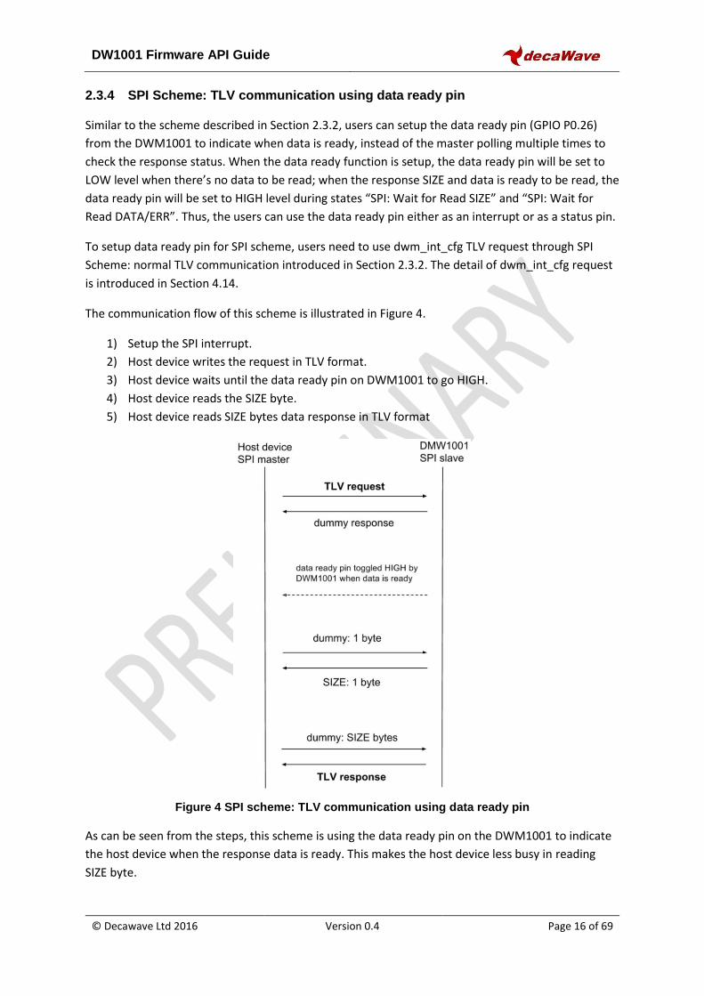
2.3.4 SPI Scheme: TLV communication using data ready pin
Similar to the scheme described in Section 2.3.2, users can setup the data ready pin (GPIO P0.26)
from the DWM1001 to indicate when data is ready, instead of the master polling multiple times to
check the response status. When the data ready function is setup, the data ready pin will be set to
LOW level when there’s no data to be read; when the response SIZE and data is ready to be read, the
data ready pin will be set to HIGH level during states “SPI: Wait for Read SIZE” and “SPI: Wait for
Read DATA/ERR”. Thus, the users can use the data ready pin either as an interrupt or as a status pin.
To setup data ready pin for SPI scheme, users need to use dwm_int_cfg TLV request through SPI
Scheme: normal TLV communication introduced in Section 2.3.2. The detail of dwm_int_cfg request
is introduced in Section 4.14.
The communication flow of this scheme is illustrated in Figure 4.
1) Setup the SPI interrupt.
2) Host device writes the request in TLV format.
3) Host device waits until the data ready pin on DWM1001 to go HIGH.
4) Host device reads the SIZE byte.
5) Host device reads SIZE bytes data response in TLV format
Figure 4 SPI scheme: TLV communication using data ready pin
As can be seen from the steps, this scheme is using the data ready pin on the DWM1001 to indicate
the host device when the response data is ready. This makes the host device less busy in reading
SIZE byte.
DW1001 Firmware API Guide
© Decawave Ltd 2016 Version 0.4 Page 17 of 69
2.3.5 SPI error recovery mechanism
2.3.5.1 SPI data doesn’t allow partial transmission
When reading data from the DWM1001 module, if the host device doesn’t read all bytes of data in
one transmission, the reading operation will still be considered as done. The rest of the response will
be abandoned. For example, in “SPI: Wait for Read DATA/ERR” state, the DWM1001 module has
prepared SIZE bytes of response data and expects the host device to read all SIZE bytes of the
response. However, if the host device only reads part of the data, the DWM1001 module will drop
the rest of the data, and transfers to the next state: “SPI: IDLE”.
2.3.5.2 SPI state recovery: type_nop message
The DWM1001 SPI has a special Type value 0xFF, called type_nop. A TLV data message with
type_nop means no operation. In “SPI: IDLE” state, when the DWM1001 SPI receives a message and
finds the type byte is 0xFF, it will not perform any operation, including sending the TLV data message
to the Generic API thread.
The type_nop is designed for error recovery. If the host device is not sure what state the DWM1001
SPI is in, it can make use of the SPI response and the non-partial transmission mechanism, and reset
the DWM1001 SPI to “SPI: IDLE” state by sending three 0xFF dummy bytes, each in a single
transmission. After the three transmissions, the response data from the DWM1001 SPI will become
all dummy bytes of value 0xFF, indicating that the DWM1001 SPI is in “SPI: IDLE” state.
DW1001 Firmware API Guide
© Decawave Ltd 2016 Version 0.4 Page 18 of 69
2.4 API via UART interface
2.4.1 DWM1001 UART overview
Users can use an external host device to connect to the DWM1001 module through UART interface
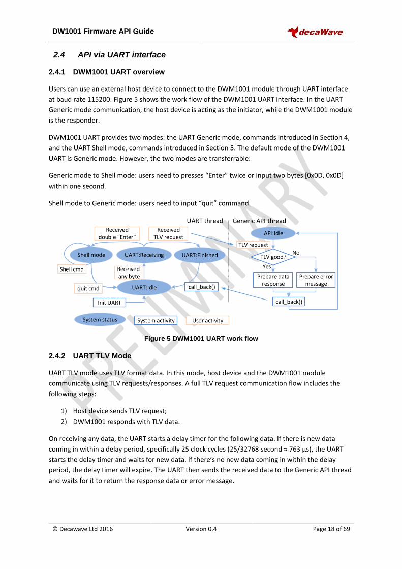
at baud rate 115200. Figure 5 shows the work flow of the DWM1001 UART interface. In the UART
Generic mode communication, the host device is acting as the initiator, while the DWM1001 module
is the responder.
DWM1001 UART provides two modes: the UART Generic mode, commands introduced in Section 4,
and the UART Shell mode, commands introduced in Section 5. The default mode of the DWM1001
UART is Generic mode. However, the two modes are transferrable:
Generic mode to Shell mode: users need to presses “Enter” twice or input two bytes [0x0D, 0x0D]
within one second.
Shell mode to Generic mode: users need to input “quit” command.
Init UART
UART:Idle
UART:Receiving UART:Finished
Received any byte
Shell mode
Received double “Enter”
ReceivedTLV request
API:Idle
TLV request
TLV good?
Prepare data response
Prepare error message
call_back()
No
Yes
call_back()
User activitySystem activitySystem status
Generic API threadUART thread
quit cmd
Shell cmd
Figure 5 DWM1001 UART work flow
2.4.2 UART TLV Mode
UART TLV mode uses TLV format data. In this mode, host device and the DWM1001 module
communicate using TLV requests/responses. A full TLV request communication flow includes the
following steps:
1) Host device sends TLV request;
2) DWM1001 responds with TLV data.
On receiving any data, the UART starts a delay timer for the following data. If there is new data
coming in within a delay period, specifically 25 clock cycles (25/32768 second ≈ 763 µs), the UART
starts the delay timer and waits for new data. If there’s no new data coming in within the delay
period, the delay timer will expire. The UART then sends the received data to the Generic API thread
and waits for it to return the response data or error message.
DW1001 Firmware API Guide
© Decawave Ltd 2016 Version 0.4 Page 19 of 69
As shown in Figure 5, the DWM1001 UART TLV mode thread transfers between three states in serial:
“UART: Idle”, “UART: Receiving” and “UART: Finished”. Each state will transfer to its next
corresponding state on certain events.
- UART: Idle: is the state after initialization and after each successful TLV response. In this
state, the UART is only expecting one byte as the start of the TLV request or the double
“Enter” command.
o Waiting for event: receiving TLV requests.
o Action on event:
Start the delay timer.
Transfer to UART: Receiving.
- UART: Receiving: is the state waiting for end of the incoming request. On receiving any data
in this state, the UART will refresh the delay timer. If the host device has finished sending
bytes, the delay timer will expire.
o Waiting for event: delay period timed out.
o Action on event - if received request is double “Enter”:
Transfer to UART Shell mode.
o Action on event - if received request is not double “Enter”:
Send received request to Generic API thread.
Transfer to UART: Finished.
- UART: Finished: is the state waiting for the Generic API thread to parse the incoming
request and send the response data or error message back to UART thread.
o Waiting for event: call_back() function called by the Generic API thread.
o Action on event:
Send the response data or error message to host device.
Transfer to UART: Idle.
2.4.3 UART scheme: TLV mode communication
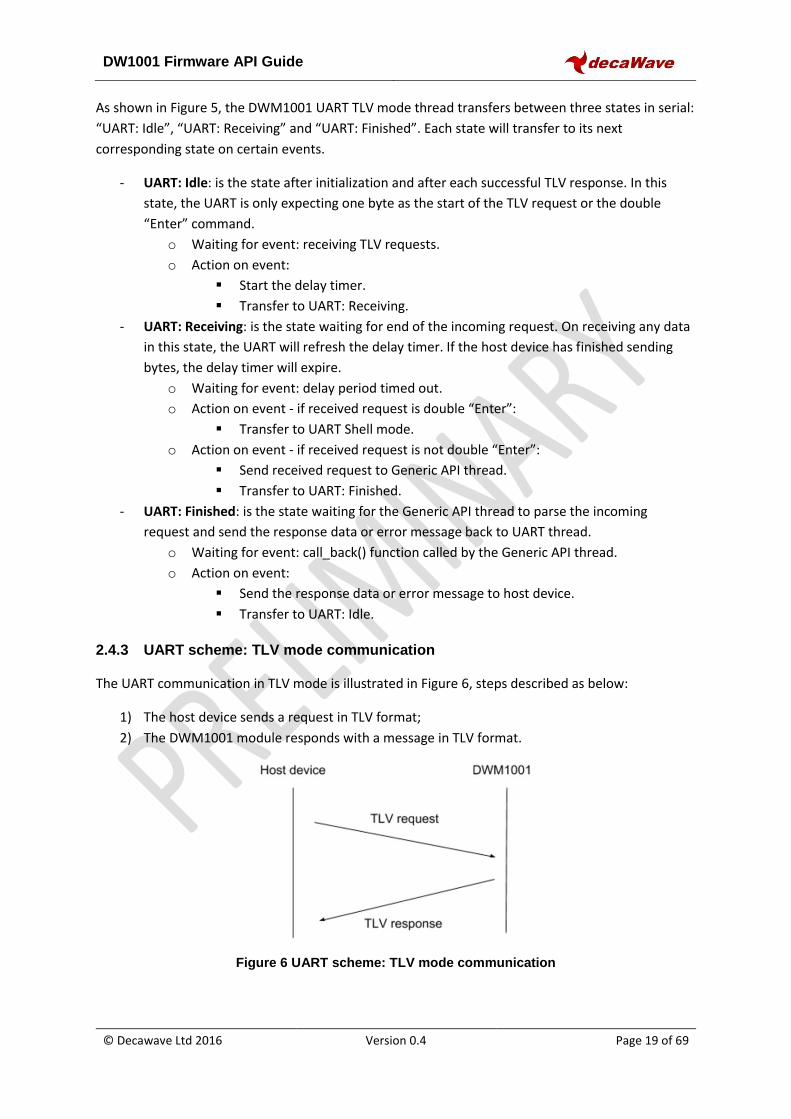
The UART communication in TLV mode is illustrated in Figure 6, steps described as below:
1) The host device sends a request in TLV format;
2) The DWM1001 module responds with a message in TLV format.
Figure 6 UART scheme: TLV mode communication
DW1001 Firmware API Guide
© Decawave Ltd 2016 Version 0.4 Page 20 of 69
2.4.4 UART example: TLV mode communication
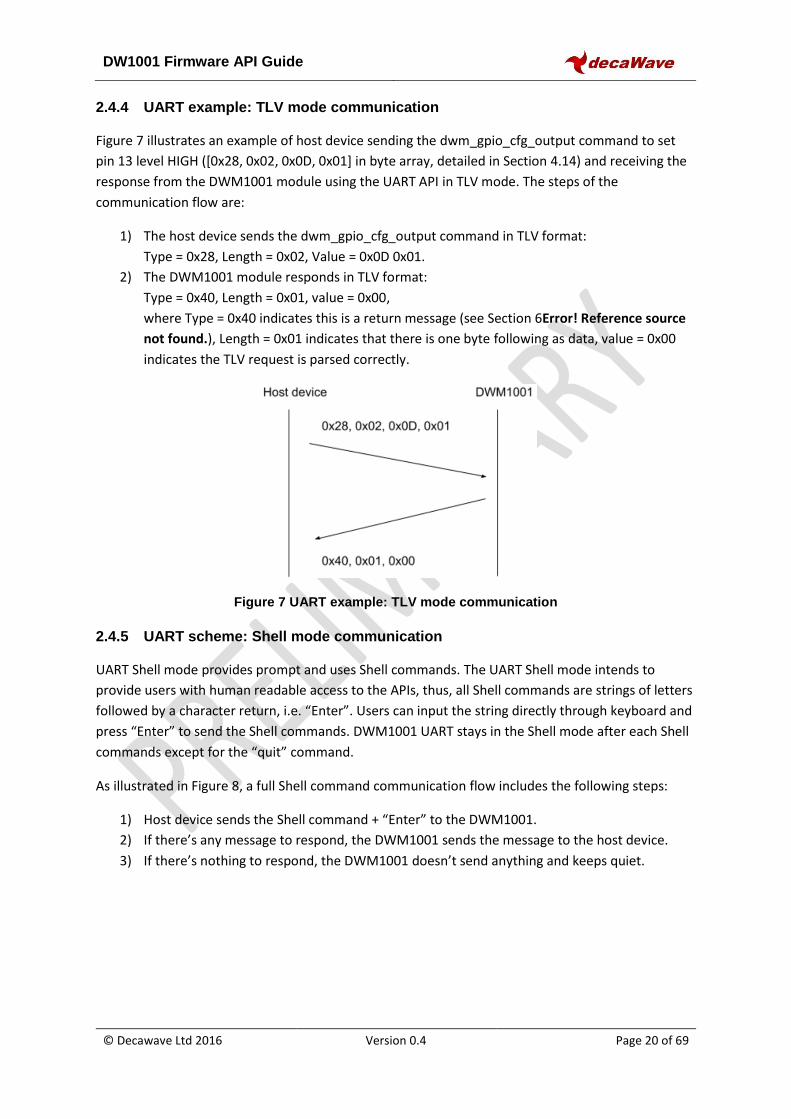
Figure 7 illustrates an example of host device sending the dwm_gpio_cfg_output command to set
pin 13 level HIGH ([0x28, 0x02, 0x0D, 0x01] in byte array, detailed in Section 4.14) and receiving the
response from the DWM1001 module using the UART API in TLV mode. The steps of the
communication flow are:
1) The host device sends the dwm_gpio_cfg_output command in TLV format:
Type = 0x28, Length = 0x02, Value = 0x0D 0x01.
2) The DWM1001 module responds in TLV format:
Type = 0x40, Length = 0x01, value = 0x00,
where Type = 0x40 indicates this is a return message (see Section 6Error! Reference source
not found.), Length = 0x01 indicates that there is one byte following as data, value = 0x00
indicates the TLV request is parsed correctly.
Figure 7 UART example: TLV mode communication
2.4.5 UART scheme: Shell mode communication
UART Shell mode provides prompt and uses Shell commands. The UART Shell mode intends to
provide users with human readable access to the APIs, thus, all Shell commands are strings of letters
followed by a character return, i.e. “Enter”. Users can input the string directly through keyboard and
press “Enter” to send the Shell commands. DWM1001 UART stays in the Shell mode after each Shell
commands except for the “quit” command.
As illustrated in Figure 8, a full Shell command communication flow includes the following steps:
1) Host device sends the Shell command + “Enter” to the DWM1001.
2) If there’s any message to respond, the DWM1001 sends the message to the host device.
3) If there’s nothing to respond, the DWM1001 doesn’t send anything and keeps quiet.
DW1001 Firmware API Guide
© Decawave Ltd 2016 Version 0.4 Page 21 of 69
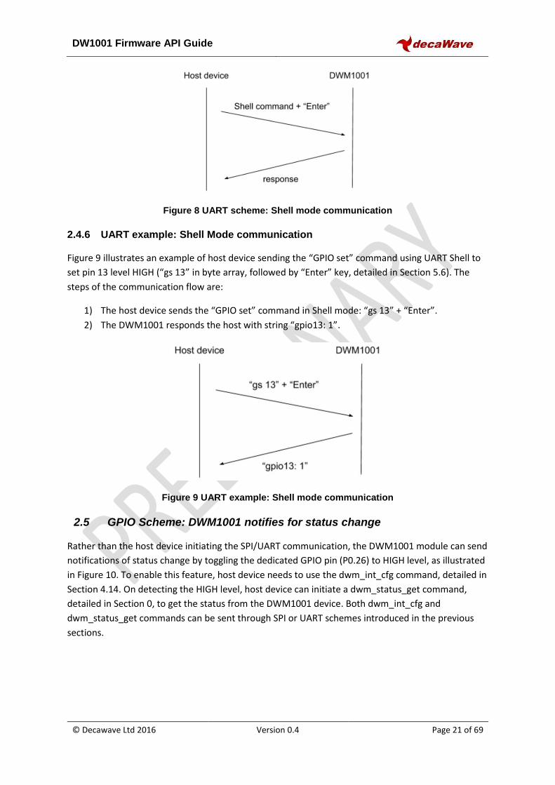
Figure 8 UART scheme: Shell mode communication
2.4.6 UART example: Shell Mode communication
Figure 9 illustrates an example of host device sending the “GPIO set” command using UART Shell to
set pin 13 level HIGH (“gs 13” in byte array, followed by “Enter” key, detailed in Section 5.6). The
steps of the communication flow are:
1) The host device sends the “GPIO set” command in Shell mode: “gs 13” + “Enter”.
2) The DWM1001 responds the host with string “gpio13: 1”.
Figure 9 UART example: Shell mode communication
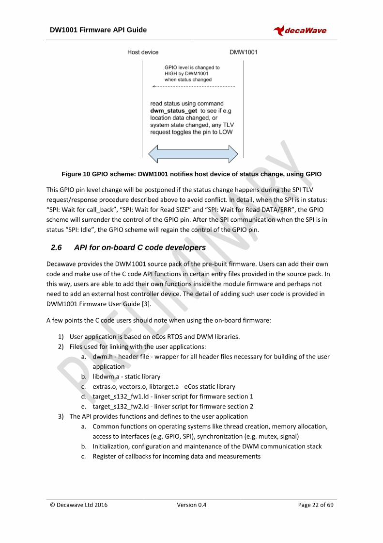
2.5 GPIO Scheme: DWM1001 notifies for status change
Rather than the host device initiating the SPI/UART communication, the DWM1001 module can send
notifications of status change by toggling the dedicated GPIO pin (P0.26) to HIGH level, as illustrated
in Figure 10. To enable this feature, host device needs to use the dwm_int_cfg command, detailed in
Section 4.14. On detecting the HIGH level, host device can initiate a dwm_status_get command,
detailed in Section 0, to get the status from the DWM1001 device. Both dwm_int_cfg and
dwm_status_get commands can be sent through SPI or UART schemes introduced in the previous
sections.
DW1001 Firmware API Guide
© Decawave Ltd 2016 Version 0.4 Page 22 of 69
Figure 10 GPIO scheme: DWM1001 notifies host device of status change, using GPIO
This GPIO pin level change will be postponed if the status change happens during the SPI TLV
request/response procedure described above to avoid conflict. In detail, when the SPI is in status:
“SPI: Wait for call_back”, “SPI: Wait for Read SIZE” and “SPI: Wait for Read DATA/ERR”, the GPIO
scheme will surrender the control of the GPIO pin. After the SPI communication when the SPI is in
status “SPI: Idle”, the GPIO scheme will regain the control of the GPIO pin.
2.6 API for on-board C code developers
Decawave provides the DWM1001 source pack of the pre-built firmware. Users can add their own
code and make use of the C code API functions in certain entry files provided in the source pack. In
this way, users are able to add their own functions inside the module firmware and perhaps not
need to add an external host controller device. The detail of adding such user code is provided in
DWM1001 Firmware User Guide [3].
A few points the C code users should note when using the on-board firmware:
1) User application is based on eCos RTOS and DWM libraries.
2) Files used for linking with the user applications:
a. dwm.h - header file - wrapper for all header files necessary for building of the user
application
b. libdwm.a - static library
c. extras.o, vectors.o, libtarget.a - eCos static library
d. target_s132_fw1.ld - linker script for firmware section 1
e. target_s132_fw2.ld - linker script for firmware section 2
3) The API provides functions and defines to the user application
a. Common functions on operating systems like thread creation, memory allocation,
access to interfaces (e.g. GPIO, SPI), synchronization (e.g. mutex, signal)
b. Initialization, configuration and maintenance of the DWM communication stack
c. Register of callbacks for incoming data and measurements
DW1001 Firmware API Guide
© Decawave Ltd 2016 Version 0.4 Page 23 of 69
3 GENERIC API INFORMATION
3.1 Used terminology
Anchor: has a fixed location – as a reference point to locate Tags. The module may be configured to
behave as an anchor node.
Tag: potentially moving location, determines dynamically its position with the help of anchors. The
module may be configured to behave as a tag node.
Gateway: knows about all nodes in the network, provides status information about network nodes
(read/inspect), cache this information and provide it to gateway client, provides means to interact
with network elements (a.k.a. interaction proxy).
Node: network node (anchor, tag, gateway...)
LE: location engine – position solver function (on the Tag)
3.2 Little endian
The integers used in the PANS API are little endian, unless otherwise stated.
3.3 Frequently used TLV values
Below lists the data that are frequently used in the APIs, either as input parameters or output
parameters. These parameters are of fixed size and some have their own value ranges.
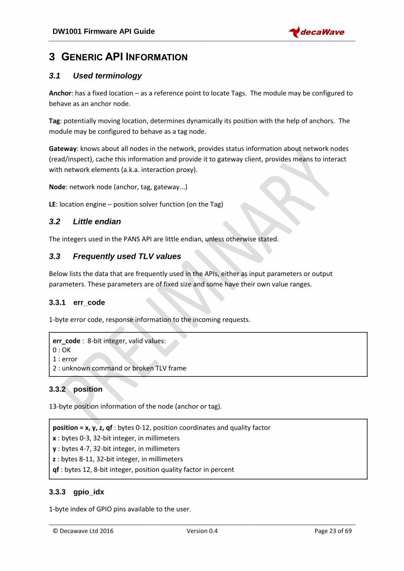
3.3.1 err_code
1-byte error code, response information to the incoming requests.
err_code : 8-bit integer, valid values: 0 : OK 1 : error 2 : unknown command or broken TLV frame
3.3.2 position
13-byte position information of the node (anchor or tag).
position = x, y, z, qf : bytes 0-12, position coordinates and quality factor
x : bytes 0-3, 32-bit integer, in millimeters
y : bytes 4-7, 32-bit integer, in millimeters
z : bytes 8-11, 32-bit integer, in millimeters
qf : bytes 12, 8-bit integer, position quality factor in percent
3.3.3 gpio_idx
1-byte index of GPIO pins available to the user.
DW1001 Firmware API Guide
© Decawave Ltd 2016 Version 0.4 Page 24 of 69
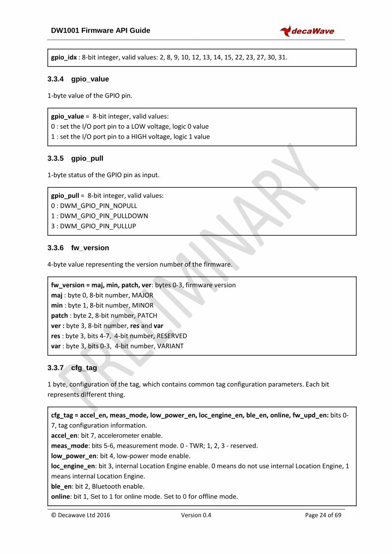
gpio_idx : 8-bit integer, valid values: 2, 8, 9, 10, 12, 13, 14, 15, 22, 23, 27, 30, 31.
3.3.4 gpio_value
1-byte value of the GPIO pin.
gpio_value = 8-bit integer, valid values:
0 : set the I/O port pin to a LOW voltage, logic 0 value
1 : set the I/O port pin to a HIGH voltage, logic 1 value
3.3.5 gpio_pull
1-byte status of the GPIO pin as input.
gpio_pull = 8-bit integer, valid values:
0 : DWM_GPIO_PIN_NOPULL
1 : DWM_GPIO_PIN_PULLDOWN
3 : DWM_GPIO_PIN_PULLUP
3.3.6 fw_version
4-byte value representing the version number of the firmware.
fw_version = maj, min, patch, ver: bytes 0-3, firmware version
maj : byte 0, 8-bit number, MAJOR
min : byte 1, 8-bit number, MINOR
patch : byte 2, 8-bit number, PATCH
ver : byte 3, 8-bit number, res and var
res : byte 3, bits 4-7, 4-bit number, RESERVED
var : byte 3, bits 0-3, 4-bit number, VARIANT
3.3.7 cfg_tag
1 byte, configuration of the tag, which contains common tag configuration parameters. Each bit
represents different thing.
cfg_tag = accel_en, meas_mode, low_power_en, loc_engine_en, ble_en, online, fw_upd_en: bits 0-
7, tag configuration information.
accel_en: bit 7, accelerometer enable.
meas_mode: bits 5-6, measurement mode. 0 - TWR; 1, 2, 3 - reserved.
low_power_en: bit 4, low-power mode enable.
loc_engine_en: bit 3, internal Location Engine enable. 0 means do not use internal Location Engine, 1
means internal Location Engine.
ble_en: bit 2, Bluetooth enable.
online: bit 1, Set to 1 for online mode. Set to 0 for offline mode.
DW1001 Firmware API Guide
© Decawave Ltd 2016 Version 0.4 Page 25 of 69
fw_upd_en: bit 0, Firmware update enable.
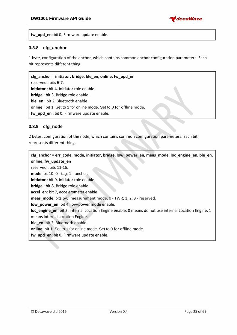
3.3.8 cfg_anchor
1 byte, configuration of the anchor, which contains common anchor configuration parameters. Each
bit represents different thing.
cfg_anchor = initiator, bridge, ble_en, online, fw_upd_en
reserved : bits 5-7.
initiator : bit 4, Initiator role enable.
bridge : bit 3, Bridge role enable.
ble_en : bit 2, Bluetooth enable.
online : bit 1, Set to 1 for online mode. Set to 0 for offline mode.
fw_upd_en : bit 0, Firmware update enable.
3.3.9 cfg_node
2 bytes, configuration of the node, which contains common configuration parameters. Each bit
represents different thing.
cfg_anchor = err_code, mode, initiator, bridge, low_power_en, meas_mode, loc_engine_en, ble_en,
online, fw_update_en
reserved : bits 11-15.
mode: bit 10, 0 - tag, 1 - anchor.
initiator : bit 9, Initiator role enable.
bridge : bit 8, Bridge role enable.
accel_en: bit 7, accelerometer enable.
meas_mode: bits 5-6, measurement mode. 0 - TWR; 1, 2, 3 - reserved.
low_power_en: bit 4, low-power mode enable.
loc_engine_en: bit 3, internal Location Engine enable. 0 means do not use internal Location Engine, 1
means internal Location Engine.
ble_en: bit 2, Bluetooth enable.
online: bit 1, Set to 1 for online mode. Set to 0 for offline mode.
fw_upd_en: bit 0, Firmware update enable.
DW1001 Firmware API Guide
© Decawave Ltd 2016 Version 0.4 Page 26 of 69
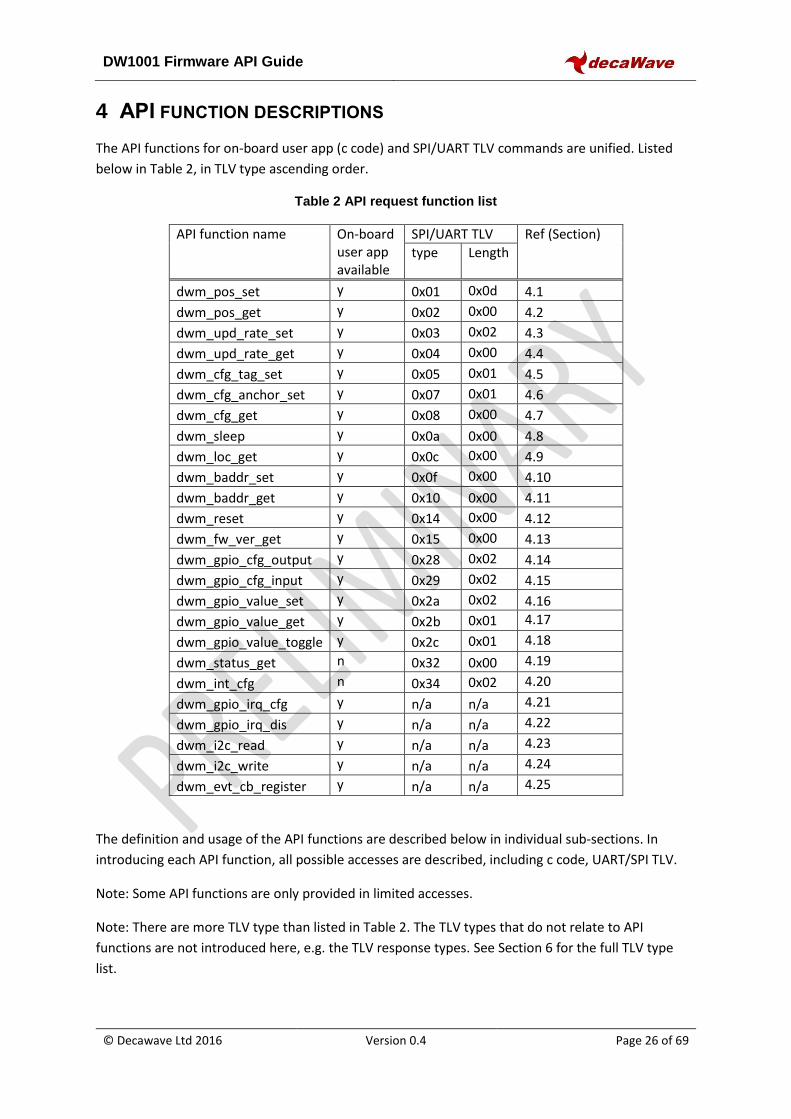
4 API FUNCTION DESCRIPTIONS
The API functions for on-board user app (c code) and SPI/UART TLV commands are unified. Listed
below in Table 2, in TLV type ascending order.
Table 2 API request function list
API function name On-board user app available
SPI/UART TLV Ref (Section)
type Length
dwm_pos_set y 0x01 0x0d 4.1
dwm_pos_get y 0x02 0x00 4.2
dwm_upd_rate_set y 0x03 0x02 4.3
dwm_upd_rate_get y 0x04 0x00 4.4
dwm_cfg_tag_set y 0x05 0x01 4.5
dwm_cfg_anchor_set y 0x07 0x01 4.6
dwm_cfg_get y 0x08 0x00 4.7
dwm_sleep y 0x0a 0x00 4.8
dwm_loc_get y 0x0c 0x00 4.9
dwm_baddr_set y 0x0f 0x00 4.10
dwm_baddr_get y 0x10 0x00 4.11
dwm_reset y 0x14 0x00 4.12
dwm_fw_ver_get y 0x15 0x00 4.13
dwm_gpio_cfg_output y 0x28 0x02 4.14
dwm_gpio_cfg_input y 0x29 0x02 4.15
dwm_gpio_value_set y 0x2a 0x02 4.16
dwm_gpio_value_get y 0x2b 0x01 4.17
dwm_gpio_value_toggle y 0x2c 0x01 4.18
dwm_status_get n 0x32 0x00 4.19
dwm_int_cfg n 0x34 0x02 4.20
dwm_gpio_irq_cfg y n/a n/a 4.21
dwm_gpio_irq_dis y n/a n/a 4.22
dwm_i2c_read y n/a n/a 4.23
dwm_i2c_write y n/a n/a 4.24
dwm_evt_cb_register y n/a n/a 4.25
The definition and usage of the API functions are described below in individual sub-sections. In
introducing each API function, all possible accesses are described, including c code, UART/SPI TLV.
Note: Some API functions are only provided in limited accesses.
Note: There are more TLV type than listed in Table 2. The TLV types that do not relate to API
functions are not introduced here, e.g. the TLV response types. See Section 6 for the full TLV type
list.
DW1001 Firmware API Guide
© Decawave Ltd 2016 Version 0.4 Page 27 of 69
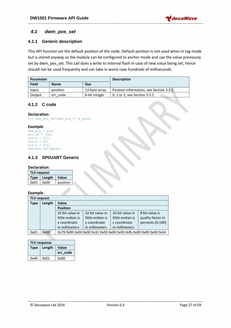
4.1 dwm_pos_set
4.1.1 Generic description
This API function set the default position of the node. Default position is not used when in tag mode
but is stored anyway so the module can be configured to anchor mode and use the value previously
set by dwm_pos_set. This call does a write to internal flash in case of new value being set, hence
should not be used frequently and can take in worst case hundreds of milliseconds.
Parameter Description
Field Name Size
Input position 13-byte array Position information, see Section 3.3.2
Output err_code 8-bit integer 0, 1 or 2, see Section 3.3.1
4.1.2 C code
Declaration: int dwm_pos_set(dwm_pos_t* p_pos);
Example: dwm_pos_t pos;
pos.qf = 100;
pos.x = 121;
pos.y = 50;
pos.z = 251;
dwm_pos_set(&pos);
4.1.3 SPI/UART Generic
Declaration: TLV request
Type Length Value
0x01 0x0D position
Example:
TLV request
Type Length Value
Position
32 bit value in little endian is x coordinate in millimeters
32 bit value in little endian is y coordinate in millimeters
32 bit value in little endian is z coordinate in millimeters
8 bit value is quality factor in percents (0-100)
0x01 0x0D 0x79 0x00 0x00 0x00 0x32 0x00 0x00 0x00 0xfb 0x00 0x00 0x00 0x64
TLV response
Type Length Value
err_code
0x40 0x01 0x00
DW1001 Firmware API Guide
© Decawave Ltd 2016 Version 0.4 Page 28 of 69
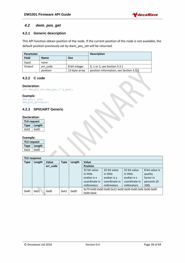
4.2 dwm_pos_get
4.2.1 Generic description
This API function obtain position of the node. If the current position of the node is not available, the
default position previously set by dwm_pos_set will be returned.
Parameter Description
Field Name Size
Input none
Output err_code 8-bit integer 0, 1 or 2, see Section 3.3.1
position 13-byte array position information, see Section 3.3.2
4.2.2 C code
Declaration: int dwm_pos_set(dwm_pos_t* p_pos);
Example: dwm_pos_t pos;
dwm_pos_get(&pos);
4.2.3 SPI/UART Generic
Declaration: TLV request
Type Length
0x02 0x00
Example:
TLV request
Type Length
0x02 0x00
TLV response
Type Length Value Type Length Value
err_code Position
32 bit value in little endian is x coordinate in millimeters
32 bit value in little endian is y coordinate in millimeters
32 bit value in little endian is z coordinate in millimeters
8 bit value is quality factor in percents (0-100)
0x40 0x01 0x00 0x41 0x0D 0x79 0x00 0x00 0x00 0x32 0x00 0x00 0x00 0xfb 0x00 0x00 0x00 0x64
DW1001 Firmware API Guide
© Decawave Ltd 2016 Version 0.4 Page 29 of 69
4.3 dwm_upd_rate_set
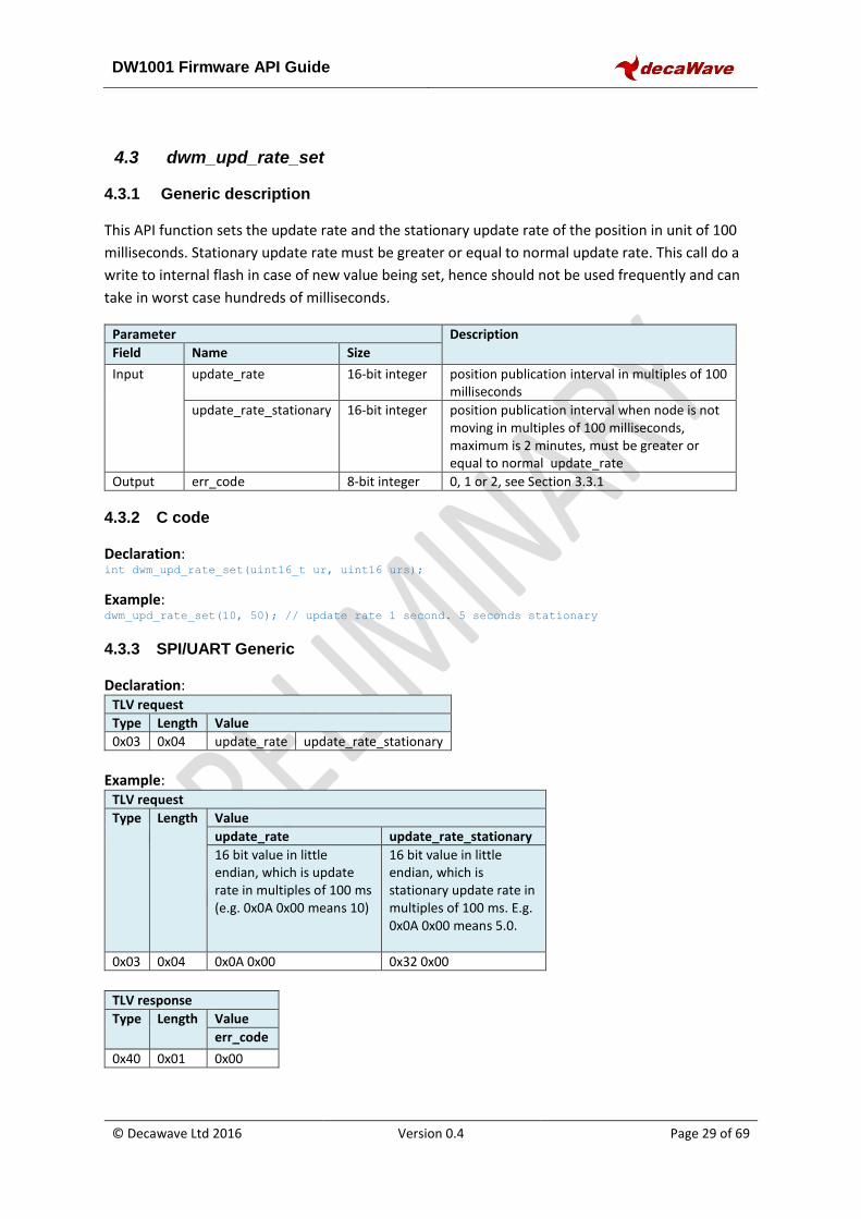
4.3.1 Generic description
This API function sets the update rate and the stationary update rate of the position in unit of 100
milliseconds. Stationary update rate must be greater or equal to normal update rate. This call do a
write to internal flash in case of new value being set, hence should not be used frequently and can
take in worst case hundreds of milliseconds.
Parameter Description
Field Name Size
Input update_rate 16-bit integer position publication interval in multiples of 100 milliseconds
update_rate_stationary 16-bit integer position publication interval when node is not moving in multiples of 100 milliseconds, maximum is 2 minutes, must be greater or equal to normal update_rate
Output err_code 8-bit integer 0, 1 or 2, see Section 3.3.1
4.3.2 C code
Declaration: int dwm_upd_rate_set(uint16_t ur, uint16 urs);
Example: dwm_upd_rate_set(10, 50); // update rate 1 second. 5 seconds stationary
4.3.3 SPI/UART Generic
Declaration: TLV request
Type Length Value
0x03 0x04 update_rate update_rate_stationary
Example:
TLV request
Type Length Value
update_rate update_rate_stationary
16 bit value in little endian, which is update rate in multiples of 100 ms (e.g. 0x0A 0x00 means 10)
16 bit value in little endian, which is stationary update rate in multiples of 100 ms. E.g. 0x0A 0x00 means 5.0.
0x03 0x04 0x0A 0x00 0x32 0x00
TLV response
Type Length Value
err_code
0x40 0x01 0x00
DW1001 Firmware API Guide
© Decawave Ltd 2016 Version 0.4 Page 30 of 69
4.4 dwm_upd_rate_get
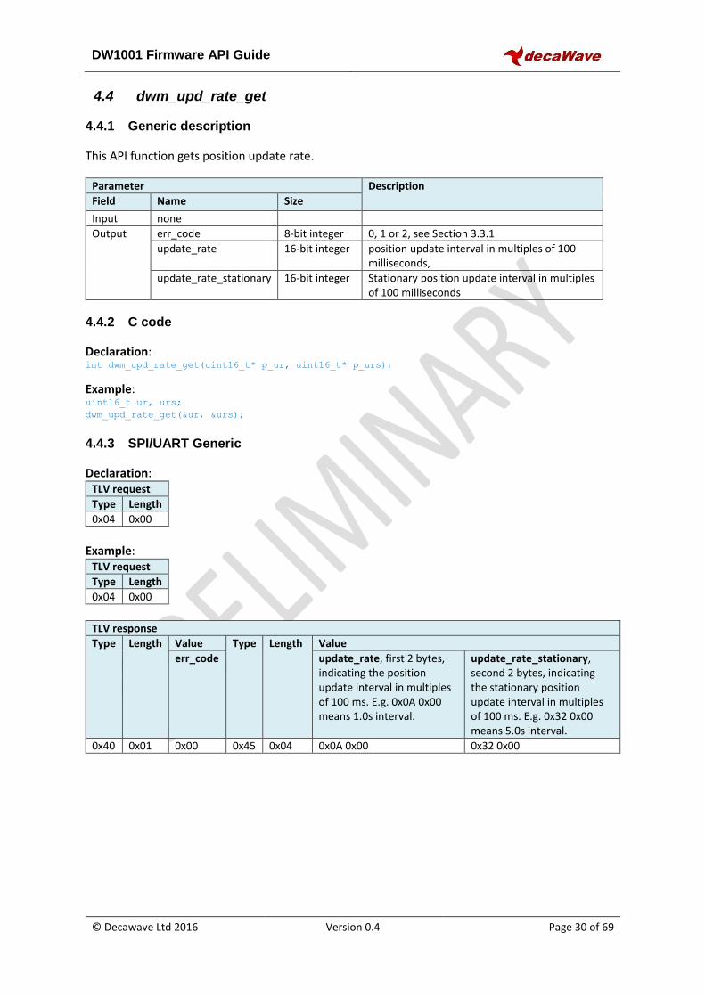
4.4.1 Generic description
This API function gets position update rate.
Parameter Description
Field Name Size
Input none
Output err_code 8-bit integer 0, 1 or 2, see Section 3.3.1
update_rate 16-bit integer position update interval in multiples of 100 milliseconds,
update_rate_stationary 16-bit integer Stationary position update interval in multiples of 100 milliseconds
4.4.2 C code
Declaration: int dwm_upd_rate_get(uint16_t* p_ur, uint16_t* p_urs);
Example: uint16_t ur, urs;
dwm_upd_rate_get(&ur, &urs);
4.4.3 SPI/UART Generic
Declaration: TLV request
Type Length
0x04 0x00
Example:
TLV request
Type Length
0x04 0x00
TLV response
Type Length Value Type Length Value
err_code update_rate, first 2 bytes, indicating the position update interval in multiples of 100 ms. E.g. 0x0A 0x00 means 1.0s interval.
update_rate_stationary, second 2 bytes, indicating the stationary position update interval in multiples of 100 ms. E.g. 0x32 0x00 means 5.0s interval.
0x40 0x01 0x00 0x45 0x04 0x0A 0x00 0x32 0x00
DW1001 Firmware API Guide
© Decawave Ltd 2016 Version 0.4 Page 31 of 69
4.5 dwm_cfg_tag_set
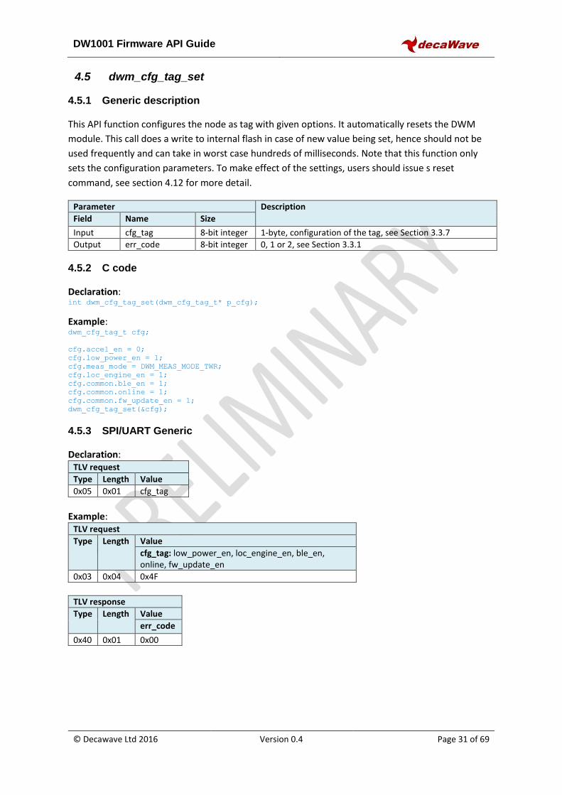
4.5.1 Generic description
This API function configures the node as tag with given options. It automatically resets the DWM
module. This call does a write to internal flash in case of new value being set, hence should not be
used frequently and can take in worst case hundreds of milliseconds. Note that this function only
sets the configuration parameters. To make effect of the settings, users should issue s reset
command, see section 4.12 for more detail.
Parameter Description
Field Name Size
Input cfg_tag 8-bit integer 1-byte, configuration of the tag, see Section 3.3.7
Output err_code 8-bit integer 0, 1 or 2, see Section 3.3.1
4.5.2 C code
Declaration: int dwm_cfg_tag_set(dwm_cfg_tag_t* p_cfg);
Example: dwm_cfg_tag_t cfg;
cfg.accel_en = 0;
cfg.low_power_en = 1;
cfg.meas_mode = DWM_MEAS_MODE_TWR;
cfg.loc_engine_en = 1;
cfg.common.ble_en = 1;
cfg.common.online = 1;
cfg.common.fw_update_en = 1;
dwm_cfg_tag_set(&cfg);
4.5.3 SPI/UART Generic
Declaration: TLV request
Type Length Value
0x05 0x01 cfg_tag
Example:
TLV request
Type Length Value
cfg_tag: low_power_en, loc_engine_en, ble_en, online, fw_update_en
0x03 0x04 0x4F
TLV response
Type Length Value
err_code
0x40 0x01 0x00
DW1001 Firmware API Guide
© Decawave Ltd 2016 Version 0.4 Page 32 of 69
4.6 dwm_cfg_anchor_set
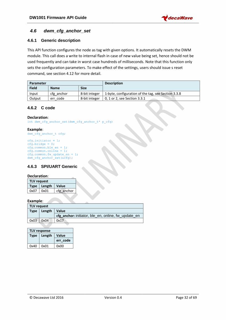
4.6.1 Generic description
This API function configures the node as tag with given options. It automatically resets the DWM
module. This call does a write to internal flash in case of new value being set, hence should not be
used frequently and can take in worst case hundreds of milliseconds. Note that this function only
sets the configuration parameters. To make effect of the settings, users should issue s reset
command, see section 4.12 for more detail.
Parameter Description
Field Name Size
Input cfg_anchor 8-bit integer 1-byte, configuration of the tag, see Section 3.3.8
Output err_code 8-bit integer 0, 1 or 2, see Section 3.3.1
4.6.2 C code
Declaration: int dwm_cfg_anchor_set(dwm_cfg_anchor_t* p_cfg)
Example: dwm_cfg_anchor_t cfg;
cfg.initiator = 1;
cfg.bridge = 0;
cfg.common.ble_en = 1;
cfg.common.online = 1;
cfg.common.fw_update_en = 1;
dwm_cfg_anchor_set(&cfg);
4.6.3 SPI/UART Generic
Declaration: TLV request
Type Length Value
0x07 0x01 cfg_anchor
Example:
TLV request
Type Length Value
cfg_anchor: initiator, ble_en, online, fw_update_en
0x03 0x04 0x17
TLV response
Type Length Value
err_code
0x40 0x01 0x00

DW1001 Firmware API Guide
© Decawave Ltd 2016 Version 0.4 Page 33 of 69
4.7 dwm_cfg_get
4.7.1 Generic description
This API function obtains the configuration of the node.
Parameter Description
Field Name Size
Input none
Output err_code 8-bit integer 0, 1 or 2, see Section 3.3.1
cfg_node 16-bit integer configuration of the node, see Section 3.3.9
4.7.2 C code
Declaration: int dwm_cfg_get(dwm_cfg_t* p_cfg);
Example: dwm_cfg_t cfg;
dwm_cfg_get(&cfg);
4.7.3 SPI/UART Generic
Declaration: TLV request
Type Length
0x08 0x00
Example:
TLV request
Type Length
0x08 0x00
TLV response
Type Length Value Type Length Value
err_code cfg_node: anchor, online, ble, fwup
0x40 0x01 0x00 0x46 0x02 0x07 0x04
DW1001 Firmware API Guide
© Decawave Ltd 2016 Version 0.4 Page 34 of 69
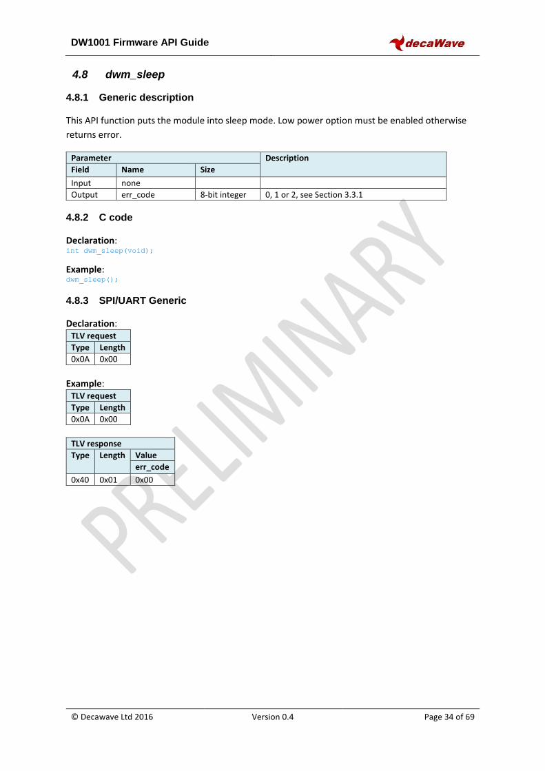
4.8 dwm_sleep
4.8.1 Generic description
This API function puts the module into sleep mode. Low power option must be enabled otherwise
returns error.
Parameter Description
Field Name Size
Input none
Output err_code 8-bit integer 0, 1 or 2, see Section 3.3.1
4.8.2 C code
Declaration: int dwm_sleep(void);
Example: dwm_sleep();
4.8.3 SPI/UART Generic
Declaration: TLV request
Type Length
0x0A 0x00
Example:
TLV request
Type Length
0x0A 0x00
TLV response
Type Length Value
err_code
0x40 0x01 0x00
DW1001 Firmware API Guide
© Decawave Ltd 2016 Version 0.4 Page 35 of 69
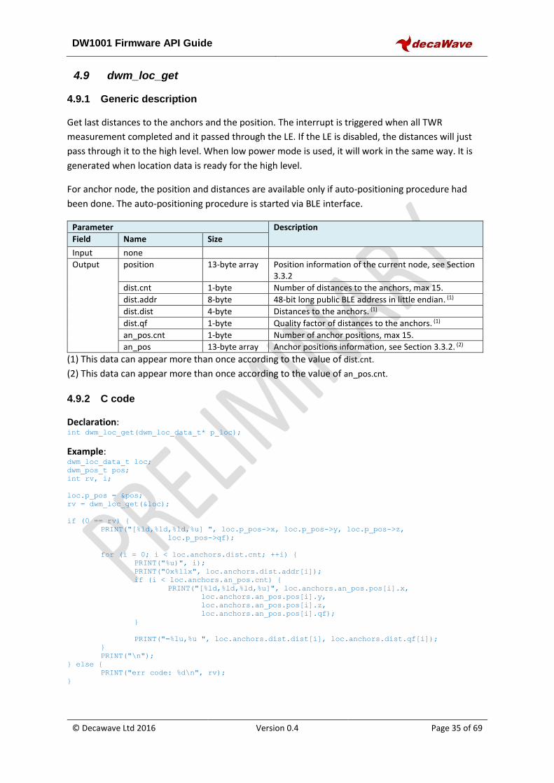
4.9 dwm_loc_get
4.9.1 Generic description
Get last distances to the anchors and the position. The interrupt is triggered when all TWR
measurement completed and it passed through the LE. If the LE is disabled, the distances will just
pass through it to the high level. When low power mode is used, it will work in the same way. It is
generated when location data is ready for the high level.
For anchor node, the position and distances are available only if auto-positioning procedure had
been done. The auto-positioning procedure is started via BLE interface.
Parameter Description
Field Name Size
Input none
Output position 13-byte array Position information of the current node, see Section 3.3.2
dist.cnt 1-byte Number of distances to the anchors, max 15.
dist.addr 8-byte 48-bit long public BLE address in little endian. (1)
dist.dist 4-byte Distances to the anchors. (1)
dist.qf 1-byte Quality factor of distances to the anchors. (1)
an_pos.cnt 1-byte Number of anchor positions, max 15.
an_pos 13-byte array Anchor positions information, see Section 3.3.2. (2)
(1) This data can appear more than once according to the value of dist.cnt.
(2) This data can appear more than once according to the value of an_pos.cnt.
4.9.2 C code
Declaration: int dwm_loc_get(dwm_loc_data_t* p_loc);
Example: dwm_loc_data_t loc;
dwm_pos_t pos;
int rv, i;
loc.p_pos = &pos;
rv = dwm_loc_get(&loc);
if (0 == rv) {
PRINT("[%ld,%ld,%ld,%u] ", loc.p_pos->x, loc.p_pos->y, loc.p_pos->z,
loc.p_pos->qf);
for (i = 0; i < loc.anchors.dist.cnt; ++i) {
PRINT("%u)", i);
PRINT("0x%llx", loc.anchors.dist.addr[i]);
if (i < loc.anchors.an_pos.cnt) {
PRINT("[%ld,%ld,%ld,%u]", loc.anchors.an_pos.pos[i].x,
loc.anchors.an_pos.pos[i].y,
loc.anchors.an_pos.pos[i].z,
loc.anchors.an_pos.pos[i].qf);
}
PRINT("=%lu,%u ", loc.anchors.dist.dist[i], loc.anchors.dist.qf[i]);
}
PRINT("\n");
} else {
PRINT("err code: %d\n", rv);
}
DW1001 Firmware API Guide
© Decawave Ltd 2016 Version 0.4 Page 36 of 69
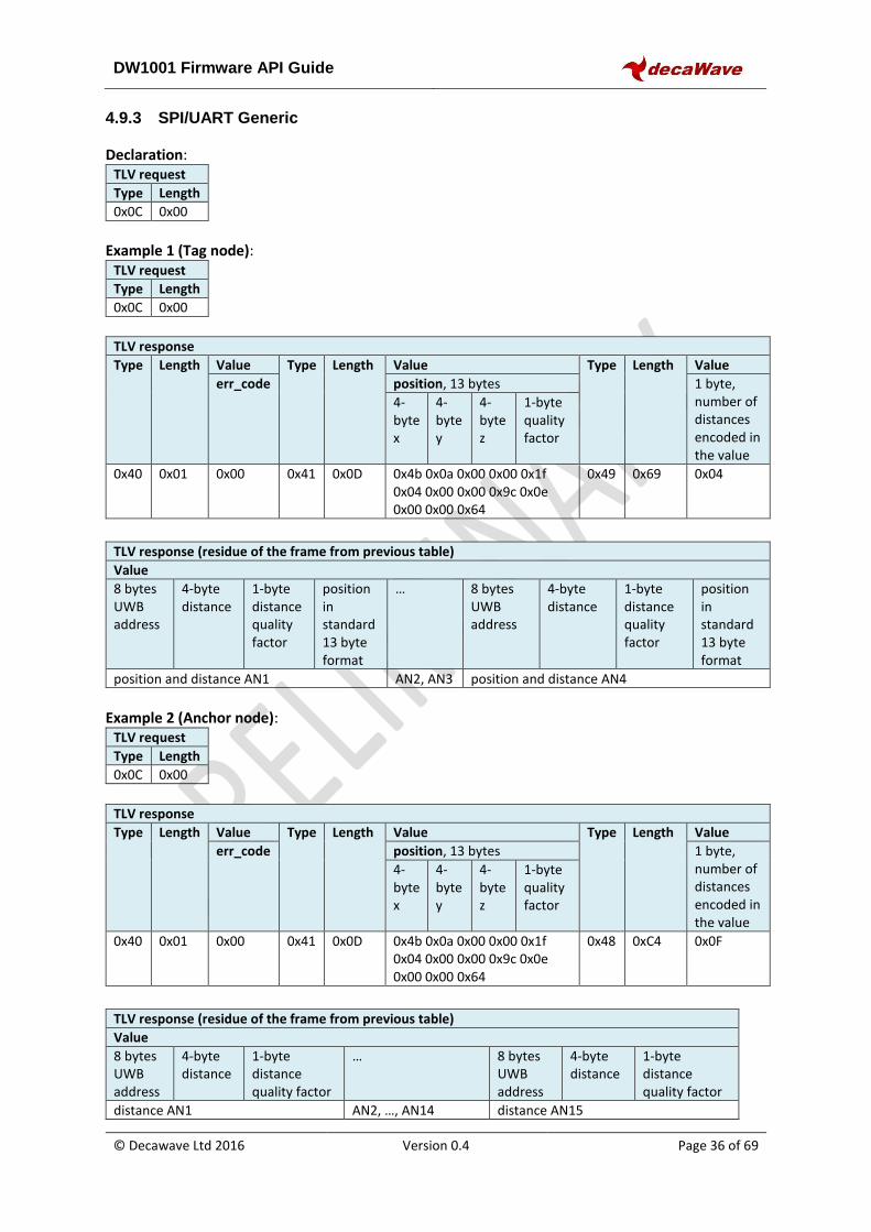
4.9.3 SPI/UART Generic
Declaration: TLV request
Type Length
0x0C 0x00
Example 1 (Tag node):
TLV request
Type Length
0x0C 0x00
TLV response
Type Length Value Type Length Value Type Length Value
err_code position, 13 bytes 1 byte, number of distances encoded in the value
4-byte x
4-byte y
4-byte z
1-byte quality factor
0x40 0x01 0x00 0x41 0x0D 0x4b 0x0a 0x00 0x00 0x1f 0x04 0x00 0x00 0x9c 0x0e 0x00 0x00 0x64
0x49 0x69 0x04
TLV response (residue of the frame from previous table)
Value
8 bytes UWB address
4-byte distance
1-byte distance quality factor
position in standard 13 byte format
…
8 bytes UWB address
4-byte distance
1-byte distance quality factor
position in standard 13 byte format
position and distance AN1 AN2, AN3 position and distance AN4
Example 2 (Anchor node):
TLV request
Type Length
0x0C 0x00
TLV response
Type Length Value Type Length Value Type Length Value
err_code position, 13 bytes 1 byte, number of distances encoded in the value
4-byte x
4-byte y
4-byte z
1-byte quality factor
0x40 0x01 0x00 0x41 0x0D 0x4b 0x0a 0x00 0x00 0x1f 0x04 0x00 0x00 0x9c 0x0e 0x00 0x00 0x64
0x48 0xC4 0x0F
TLV response (residue of the frame from previous table)
Value
8 bytes UWB address
4-byte distance
1-byte distance quality factor
…
8 bytes UWB address
4-byte distance
1-byte distance quality factor
distance AN1 AN2, …, AN14 distance AN15
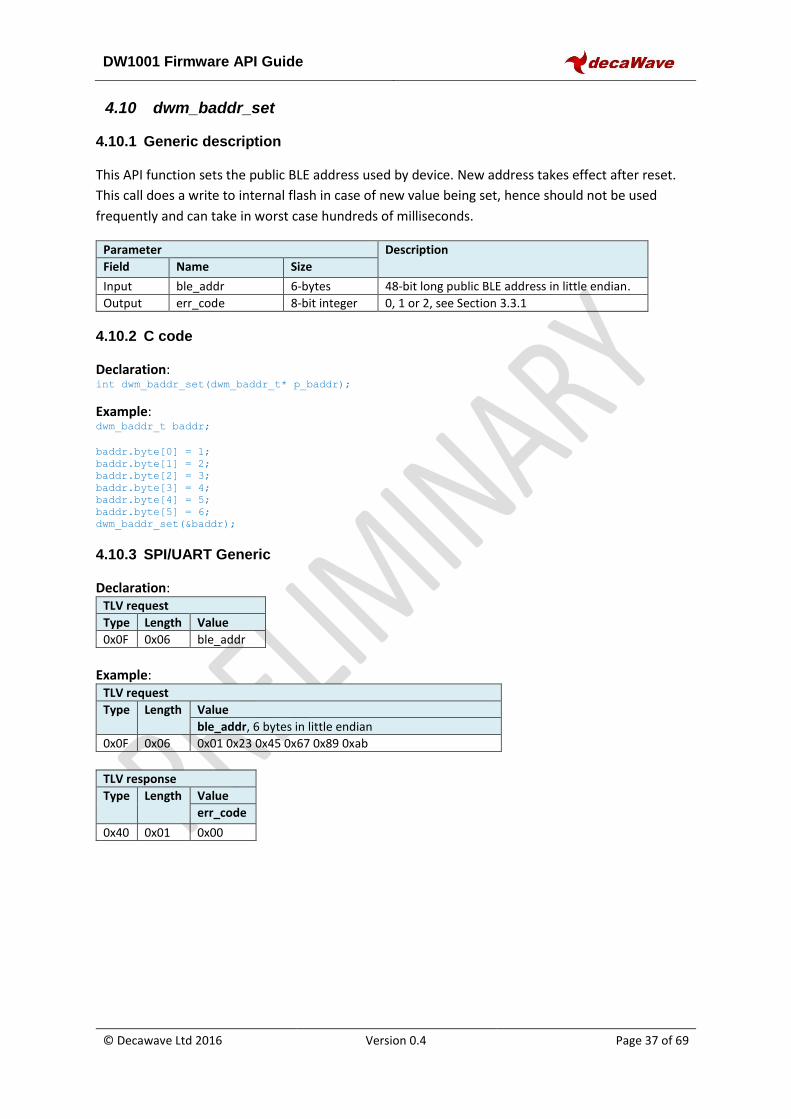
DW1001 Firmware API Guide
© Decawave Ltd 2016 Version 0.4 Page 37 of 69
4.10 dwm_baddr_set
4.10.1 Generic description
This API function sets the public BLE address used by device. New address takes effect after reset.
This call does a write to internal flash in case of new value being set, hence should not be used
frequently and can take in worst case hundreds of milliseconds.
Parameter Description
Field Name Size
Input ble_addr 6-bytes 48-bit long public BLE address in little endian.
Output err_code 8-bit integer 0, 1 or 2, see Section 3.3.1
4.10.2 C code
Declaration: int dwm_baddr_set(dwm_baddr_t* p_baddr);
Example: dwm_baddr_t baddr;
baddr.byte[0] = 1;
baddr.byte[1] = 2;
baddr.byte[2] = 3;
baddr.byte[3] = 4;
baddr.byte[4] = 5;
baddr.byte[5] = 6;
dwm_baddr_set(&baddr);
4.10.3 SPI/UART Generic
Declaration: TLV request
Type Length Value
0x0F 0x06 ble_addr
Example:
TLV request
Type Length Value
ble_addr, 6 bytes in little endian
0x0F 0x06 0x01 0x23 0x45 0x67 0x89 0xab
TLV response
Type Length Value
err_code
0x40 0x01 0x00
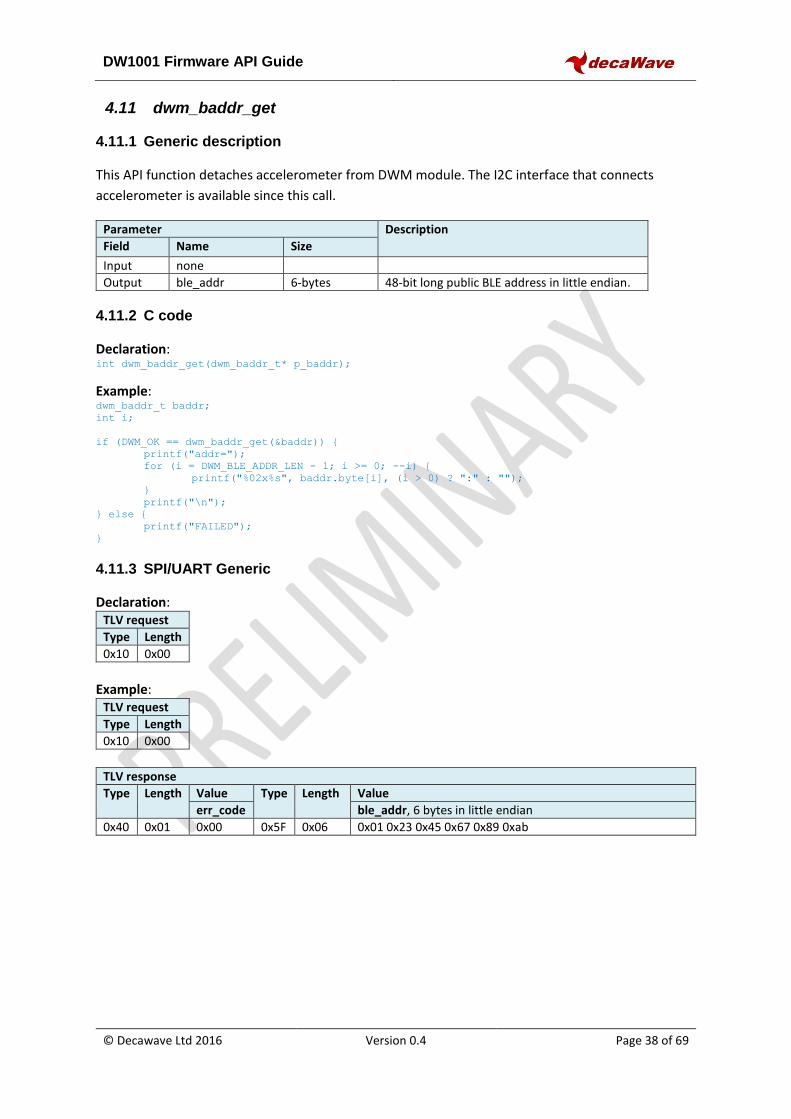
DW1001 Firmware API Guide
© Decawave Ltd 2016 Version 0.4 Page 38 of 69
4.11 dwm_baddr_get
4.11.1 Generic description
This API function detaches accelerometer from DWM module. The I2C interface that connects
accelerometer is available since this call.
Parameter Description
Field Name Size
Input none
Output ble_addr 6-bytes 48-bit long public BLE address in little endian.
4.11.2 C code
Declaration: int dwm_baddr_get(dwm_baddr_t* p_baddr);
Example: dwm_baddr_t baddr;
int i;
if (DWM_OK == dwm_baddr_get(&baddr)) {
printf("addr=");
for (i = DWM_BLE_ADDR_LEN - 1; i >= 0; --i) {
printf("%02x%s", baddr.byte[i], (i > 0) ? ":" : "");
}
printf("\n");
} else {
printf("FAILED");
}
4.11.3 SPI/UART Generic
Declaration: TLV request
Type Length
0x10 0x00
Example:
TLV request
Type Length
0x10 0x00
TLV response
Type Length Value Type Length Value
err_code ble_addr, 6 bytes in little endian 0x40 0x01 0x00 0x5F 0x06 0x01 0x23 0x45 0x67 0x89 0xab
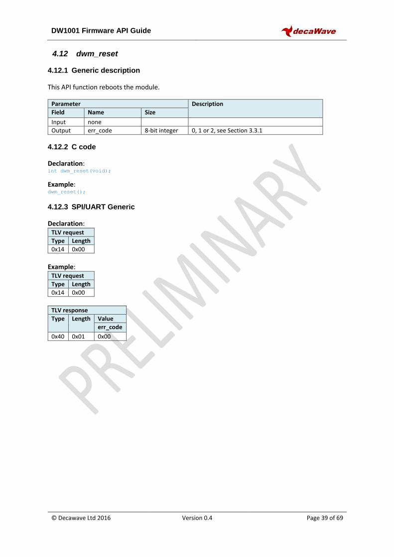
DW1001 Firmware API Guide
© Decawave Ltd 2016 Version 0.4 Page 39 of 69
4.12 dwm_reset
4.12.1 Generic description
This API function reboots the module.
Parameter Description
Field Name Size
Input none
Output err_code 8-bit integer 0, 1 or 2, see Section 3.3.1
4.12.2 C code
Declaration: int dwm_reset(void);
Example: dwm_reset();
4.12.3 SPI/UART Generic
Declaration: TLV request
Type Length
0x14 0x00
Example:
TLV request
Type Length
0x14 0x00
TLV response
Type Length Value
err_code
0x40 0x01 0x00
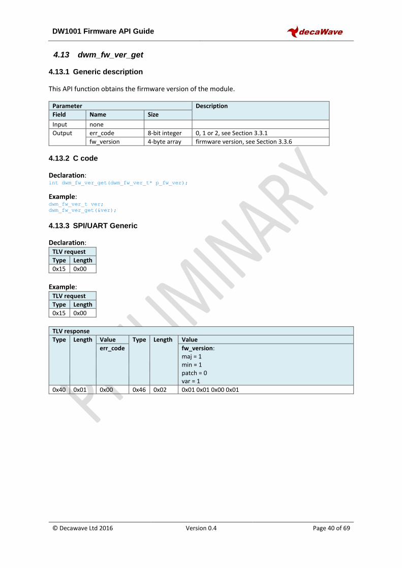
DW1001 Firmware API Guide
© Decawave Ltd 2016 Version 0.4 Page 40 of 69
4.13 dwm_fw_ver_get
4.13.1 Generic description
This API function obtains the firmware version of the module.
Parameter Description
Field Name Size
Input none
Output err_code 8-bit integer 0, 1 or 2, see Section 3.3.1
fw_version 4-byte array firmware version, see Section 3.3.6
4.13.2 C code
Declaration: int dwm_fw_ver_get(dwm_fw_ver_t* p_fw_ver);
Example: dwm_fw_ver_t ver;
dwm_fw_ver_get(&ver);
4.13.3 SPI/UART Generic
Declaration: TLV request
Type Length
0x15 0x00
Example:
TLV request
Type Length
0x15 0x00
TLV response
Type Length Value Type Length Value
err_code fw_version: maj = 1 min = 1 patch = 0 var = 1
0x40 0x01 0x00 0x46 0x02 0x01 0x01 0x00 0x01
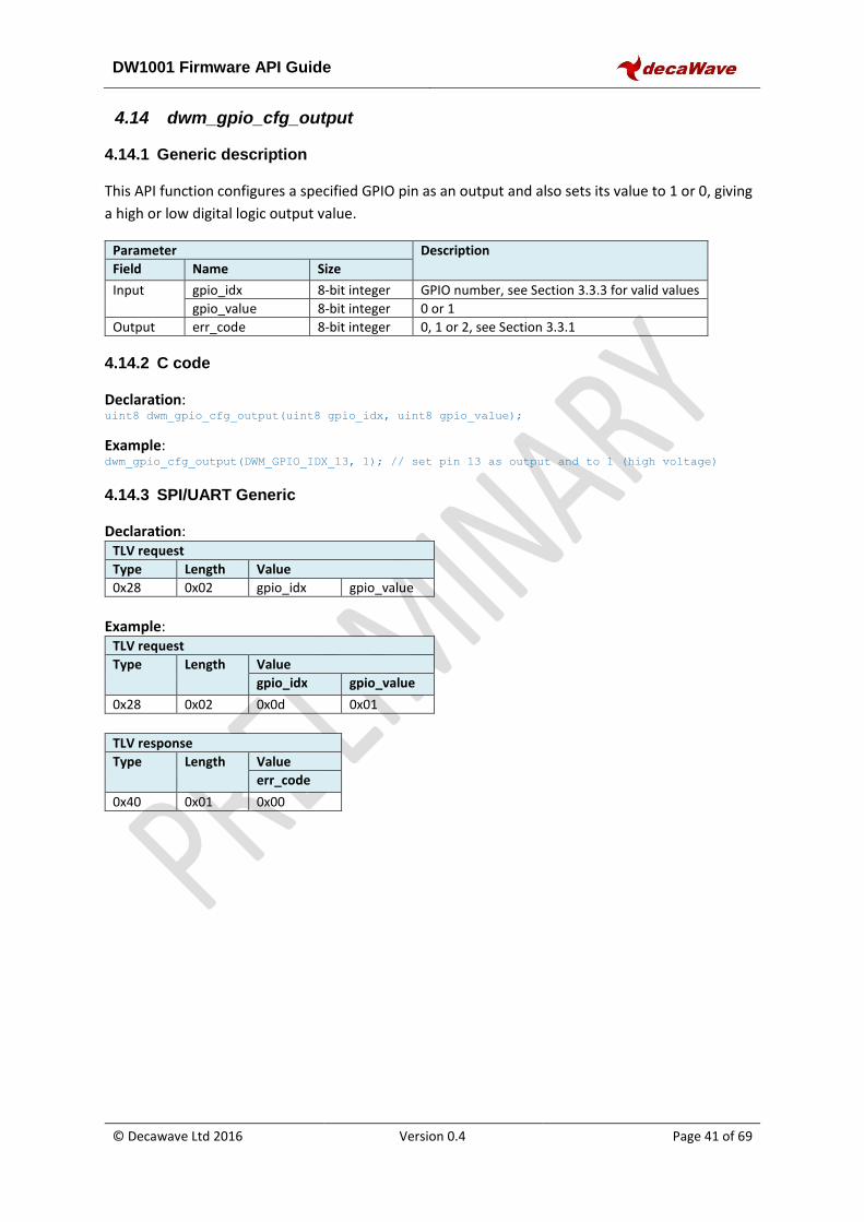
DW1001 Firmware API Guide
© Decawave Ltd 2016 Version 0.4 Page 41 of 69
4.14 dwm_gpio_cfg_output
4.14.1 Generic description
This API function configures a specified GPIO pin as an output and also sets its value to 1 or 0, giving
a high or low digital logic output value.
Parameter Description
Field Name Size
Input gpio_idx 8-bit integer GPIO number, see Section 3.3.3 for valid values
gpio_value 8-bit integer 0 or 1
Output err_code 8-bit integer 0, 1 or 2, see Section 3.3.1
4.14.2 C code
Declaration: uint8 dwm_gpio_cfg_output(uint8 gpio_idx, uint8 gpio_value);
Example: dwm_gpio_cfg_output(DWM_GPIO_IDX_13, 1); // set pin 13 as output and to 1 (high voltage)
4.14.3 SPI/UART Generic
Declaration: TLV request
Type Length Value
0x28 0x02 gpio_idx gpio_value
Example:
TLV request
Type Length Value
gpio_idx gpio_value
0x28 0x02 0x0d 0x01
TLV response
Type Length Value
err_code
0x40 0x01 0x00
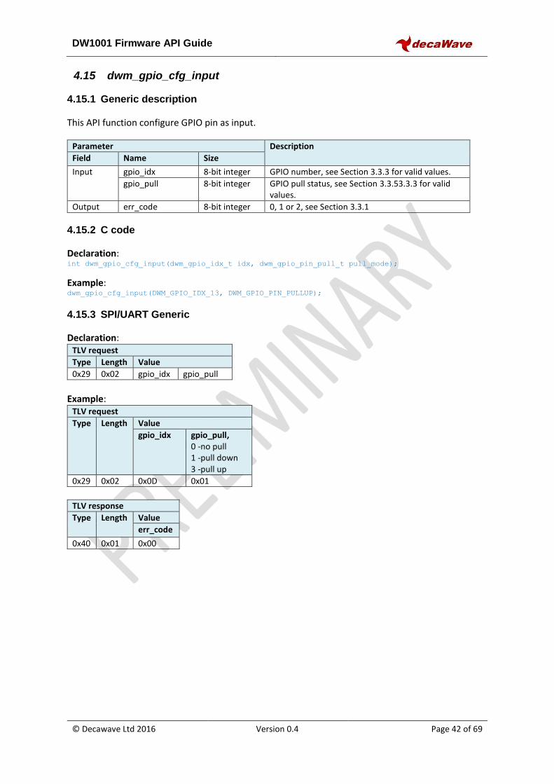
DW1001 Firmware API Guide
© Decawave Ltd 2016 Version 0.4 Page 42 of 69
4.15 dwm_gpio_cfg_input
4.15.1 Generic description
This API function configure GPIO pin as input.
Parameter Description
Field Name Size
Input gpio_idx 8-bit integer GPIO number, see Section 3.3.3 for valid values.
gpio_pull 8-bit integer GPIO pull status, see Section 3.3.53.3.3 for valid values.
Output err_code 8-bit integer 0, 1 or 2, see Section 3.3.1
4.15.2 C code
Declaration: int dwm_gpio_cfg_input(dwm_gpio_idx_t idx, dwm_gpio_pin_pull_t pull_mode);
Example: dwm_gpio_cfg_input(DWM_GPIO_IDX_13, DWM_GPIO_PIN_PULLUP);
4.15.3 SPI/UART Generic
Declaration: TLV request
Type Length Value
0x29 0x02 gpio_idx gpio_pull
Example:
TLV request
Type Length Value
gpio_idx gpio_pull, 0 -no pull 1 -pull down 3 -pull up
0x29 0x02 0x0D 0x01
TLV response
Type Length Value
err_code
0x40 0x01 0x00
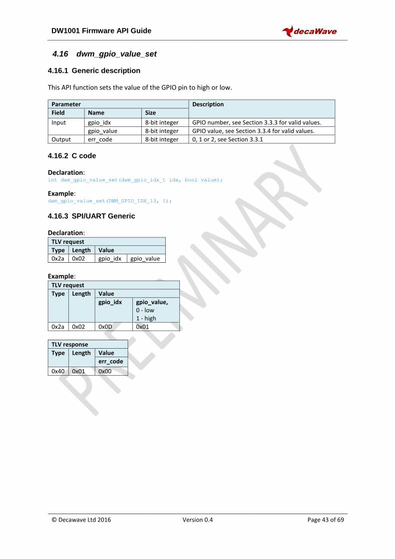
DW1001 Firmware API Guide
© Decawave Ltd 2016 Version 0.4 Page 43 of 69
4.16 dwm_gpio_value_set
4.16.1 Generic description
This API function sets the value of the GPIO pin to high or low.
Parameter Description
Field Name Size
Input gpio_idx 8-bit integer GPIO number, see Section 3.3.3 for valid values.
gpio_value 8-bit integer GPIO value, see Section 3.3.4 for valid values.
Output err_code 8-bit integer 0, 1 or 2, see Section 3.3.1
4.16.2 C code
Declaration: int dwm_gpio_value_set(dwm_gpio_idx_t idx, bool value);
Example: dwm_gpio_value_set(DWM_GPIO_IDX_13, 1);
4.16.3 SPI/UART Generic
Declaration: TLV request
Type Length Value
0x2a 0x02 gpio_idx gpio_value
Example:
TLV request
Type Length Value
gpio_idx gpio_value, 0 - low 1 - high
0x2a 0x02 0x0D 0x01
TLV response
Type Length Value
err_code
0x40 0x01 0x00
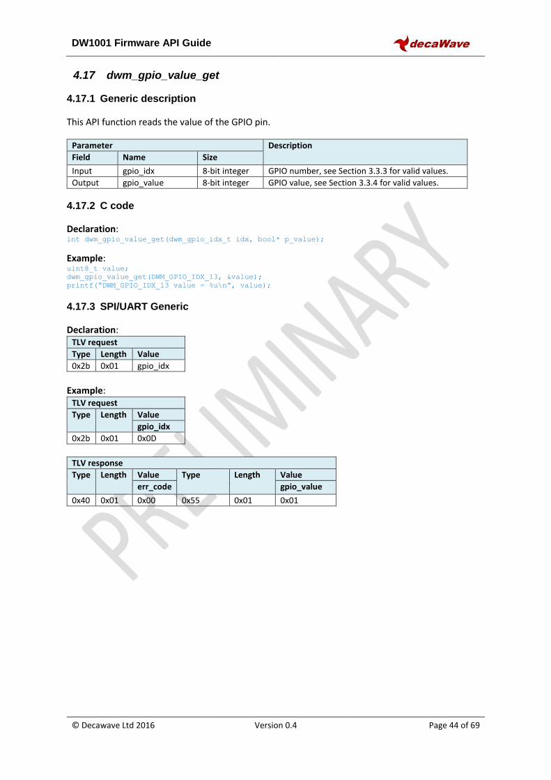
DW1001 Firmware API Guide
© Decawave Ltd 2016 Version 0.4 Page 44 of 69
4.17 dwm_gpio_value_get
4.17.1 Generic description
This API function reads the value of the GPIO pin.
Parameter Description
Field Name Size
Input gpio_idx 8-bit integer GPIO number, see Section 3.3.3 for valid values.
Output gpio_value 8-bit integer GPIO value, see Section 3.3.4 for valid values.
4.17.2 C code
Declaration: int dwm_gpio_value_get(dwm_gpio_idx_t idx, bool* p_value);
Example: uint8_t value; dwm_gpio_value_get(DWM_GPIO_IDX_13, &value);
printf(“DWM_GPIO_IDX_13 value = %u\n”, value);
4.17.3 SPI/UART Generic
Declaration: TLV request
Type Length Value
0x2b 0x01 gpio_idx
Example:
TLV request
Type Length Value
gpio_idx
0x2b 0x01 0x0D
TLV response
Type Length Value Type Length Value err_code gpio_value
0x40 0x01 0x00 0x55 0x01 0x01
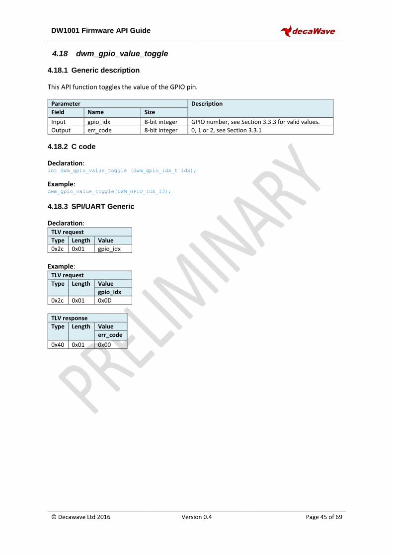
DW1001 Firmware API Guide
© Decawave Ltd 2016 Version 0.4 Page 45 of 69
4.18 dwm_gpio_value_toggle
4.18.1 Generic description
This API function toggles the value of the GPIO pin.
Parameter Description
Field Name Size
Input gpio_idx 8-bit integer GPIO number, see Section 3.3.3 for valid values.
Output err_code 8-bit integer 0, 1 or 2, see Section 3.3.1
4.18.2 C code
Declaration: int dwm_gpio_value_toggle (dwm_gpio_idx_t idx);
Example: dwm_gpio_value_toggle(DWM_GPIO_IDX_13);
4.18.3 SPI/UART Generic
Declaration: TLV request
Type Length Value
0x2c 0x01 gpio_idx
Example:
TLV request
Type Length Value
gpio_idx
0x2c 0x01 0x0D
TLV response
Type Length Value
err_code
0x40 0x01 0x00
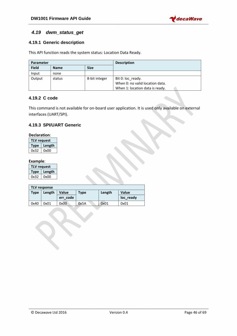
DW1001 Firmware API Guide
© Decawave Ltd 2016 Version 0.4 Page 46 of 69
4.19 dwm_status_get
4.19.1 Generic description
This API function reads the system status: Location Data Ready.
Parameter Description
Field Name Size
Input none
Output status 8-bit integer Bit 0: loc_ready. When 0: no valid location data. When 1: location data is ready.
4.19.2 C code
This command is not available for on-board user application. It is used only available on external
interfaces (UART/SPI).
4.19.3 SPI/UART Generic
Declaration: TLV request
Type Length
0x32 0x00
Example:
TLV request
Type Length
0x32 0x00
TLV response
Type Length Value Type Length Value err_code loc_ready
0x40 0x01 0x00 0x5A 0x01 0x01
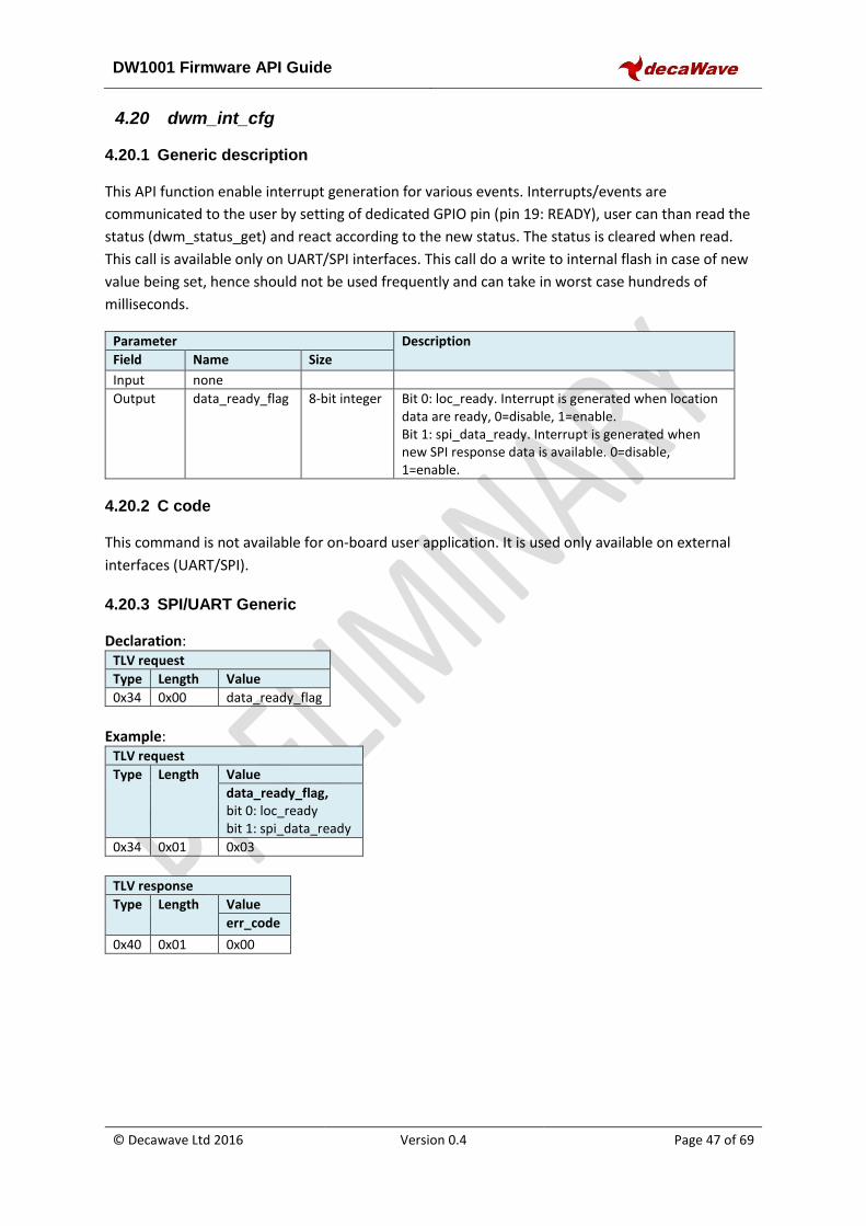
DW1001 Firmware API Guide
© Decawave Ltd 2016 Version 0.4 Page 47 of 69
4.20 dwm_int_cfg
4.20.1 Generic description
This API function enable interrupt generation for various events. Interrupts/events are
communicated to the user by setting of dedicated GPIO pin (pin 19: READY), user can than read the
status (dwm_status_get) and react according to the new status. The status is cleared when read.
This call is available only on UART/SPI interfaces. This call do a write to internal flash in case of new
value being set, hence should not be used frequently and can take in worst case hundreds of
milliseconds.
Parameter Description
Field Name Size
Input none
Output data_ready_flag 8-bit integer Bit 0: loc_ready. Interrupt is generated when location data are ready, 0=disable, 1=enable. Bit 1: spi_data_ready. Interrupt is generated when new SPI response data is available. 0=disable, 1=enable.
4.20.2 C code
This command is not available for on-board user application. It is used only available on external
interfaces (UART/SPI).
4.20.3 SPI/UART Generic
Declaration: TLV request
Type Length Value
0x34 0x00 data_ready_flag
Example:
TLV request
Type Length Value
data_ready_flag, bit 0: loc_ready bit 1: spi_data_ready
0x34 0x01 0x03
TLV response
Type Length Value
err_code
0x40 0x01 0x00
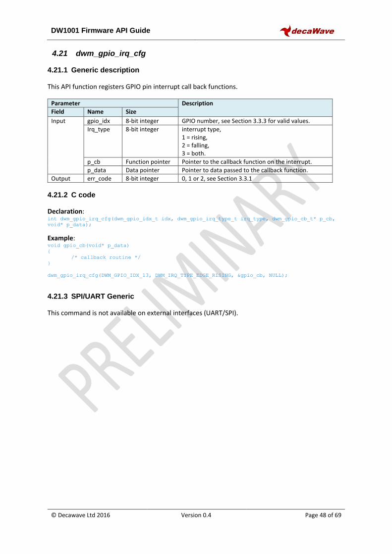
DW1001 Firmware API Guide
© Decawave Ltd 2016 Version 0.4 Page 48 of 69
4.21 dwm_gpio_irq_cfg
4.21.1 Generic description
This API function registers GPIO pin interrupt call back functions.
Parameter Description
Field Name Size
Input gpio_idx 8-bit integer GPIO number, see Section 3.3.3 for valid values.
Irq_type 8-bit integer interrupt type, 1 = rising, 2 = falling, 3 = both.
p_cb Function pointer Pointer to the callback function on the interrupt.
p_data Data pointer Pointer to data passed to the callback function.
Output err_code 8-bit integer 0, 1 or 2, see Section 3.3.1
4.21.2 C code
Declaration: int dwm_gpio_irq_cfg(dwm_gpio_idx_t idx, dwm_gpio_irq_type_t irq_type, dwm_gpio_cb_t* p_cb,
void* p_data);
Example: void gpio_cb(void* p_data)
{
/* callback routine */
}
dwm_gpio_irq_cfg(DWM_GPIO_IDX_13, DWM_IRQ_TYPE_EDGE_RISING, &gpio_cb, NULL);
4.21.3 SPI/UART Generic
This command is not available on external interfaces (UART/SPI).
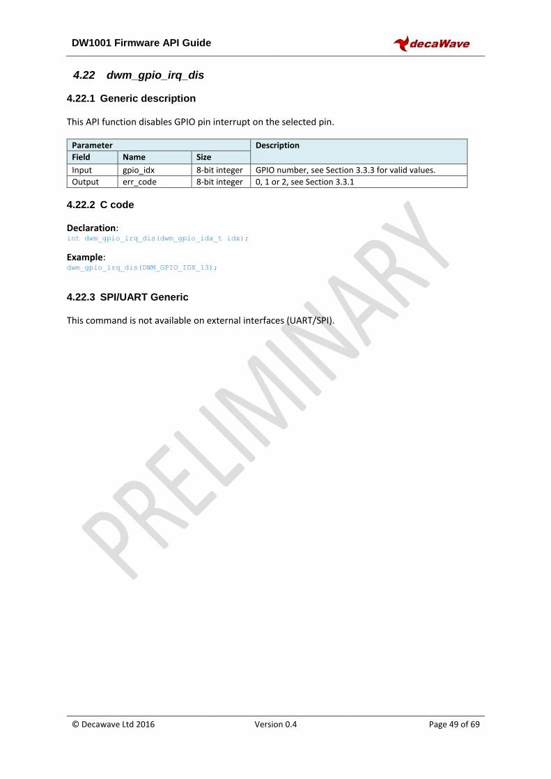
DW1001 Firmware API Guide
© Decawave Ltd 2016 Version 0.4 Page 49 of 69
4.22 dwm_gpio_irq_dis
4.22.1 Generic description
This API function disables GPIO pin interrupt on the selected pin.
Parameter Description
Field Name Size
Input gpio_idx 8-bit integer GPIO number, see Section 3.3.3 for valid values.
Output err_code 8-bit integer 0, 1 or 2, see Section 3.3.1
4.22.2 C code
Declaration: int dwm_gpio_irq_dis(dwm_gpio_idx_t idx);
Example: dwm_gpio_irq_dis(DWM_GPIO_IDX_13);
4.22.3 SPI/UART Generic
This command is not available on external interfaces (UART/SPI).
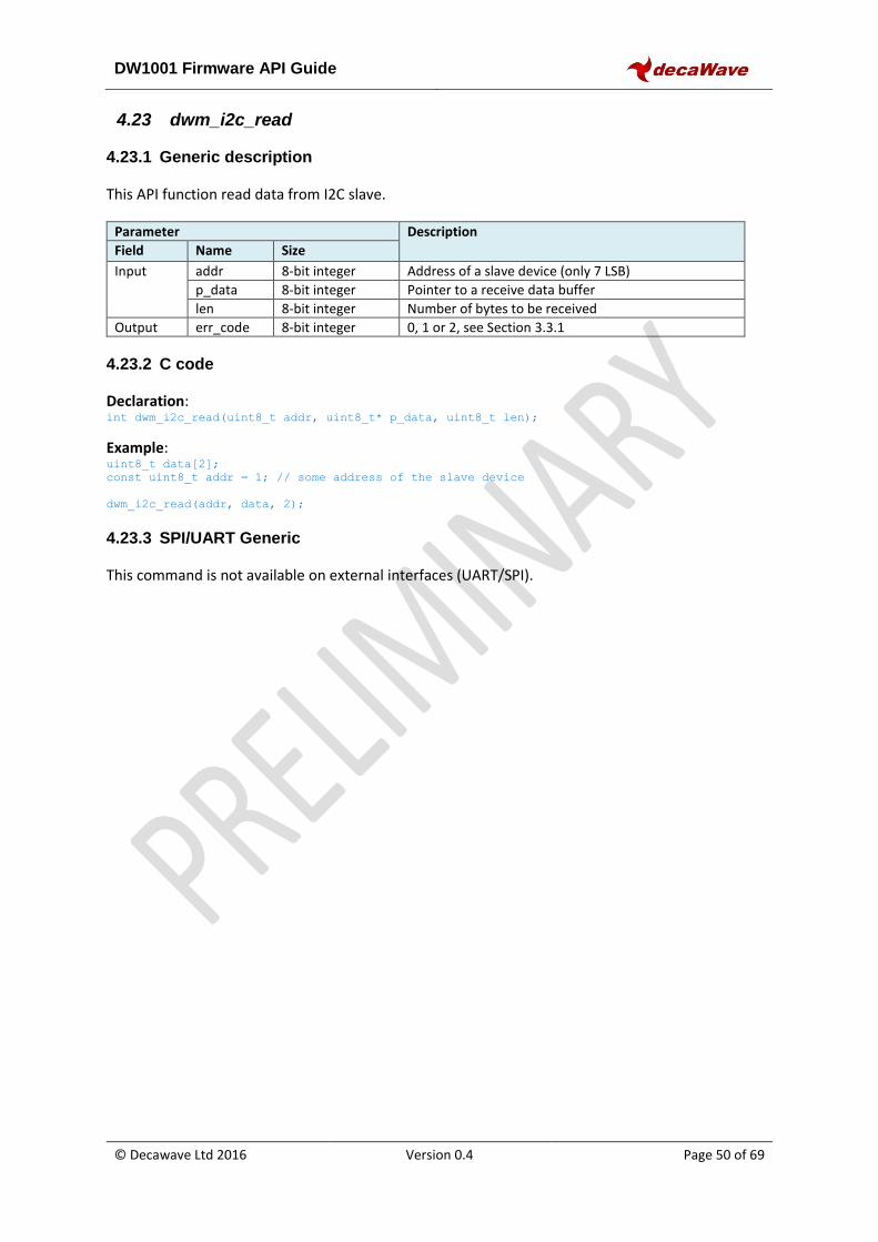
DW1001 Firmware API Guide
© Decawave Ltd 2016 Version 0.4 Page 50 of 69
4.23 dwm_i2c_read
4.23.1 Generic description
This API function read data from I2C slave.
Parameter Description
Field Name Size
Input addr 8-bit integer Address of a slave device (only 7 LSB)
p_data 8-bit integer Pointer to a receive data buffer
len 8-bit integer Number of bytes to be received
Output err_code 8-bit integer 0, 1 or 2, see Section 3.3.1
4.23.2 C code
Declaration: int dwm_i2c_read(uint8_t addr, uint8_t* p_data, uint8_t len);
Example: uint8_t data[2];
const uint8_t addr = 1; // some address of the slave device
dwm_i2c_read(addr, data, 2);
4.23.3 SPI/UART Generic
This command is not available on external interfaces (UART/SPI).
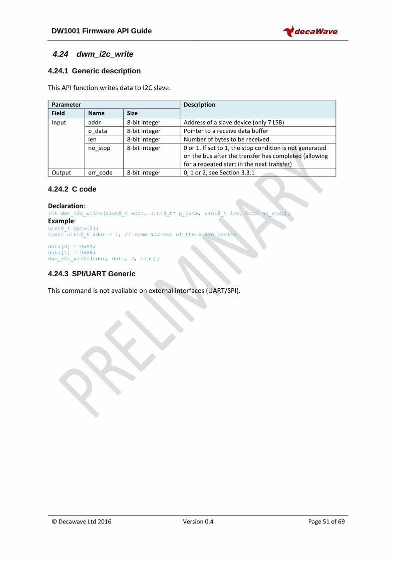
DW1001 Firmware API Guide
© Decawave Ltd 2016 Version 0.4 Page 51 of 69
4.24 dwm_i2c_write
4.24.1 Generic description
This API function writes data to I2C slave.
Parameter Description
Field Name Size
Input addr 8-bit integer Address of a slave device (only 7 LSB)
p_data 8-bit integer Pointer to a receive data buffer
len 8-bit integer Number of bytes to be received
no_stop 8-bit integer 0 or 1. If set to 1, the stop condition is not generated on the bus after the transfer has completed (allowing for a repeated start in the next transfer)
Output err_code 8-bit integer 0, 1 or 2, see Section 3.3.1
4.24.2 C code
Declaration: int dwm_i2c_write(uint8_t addr, uint8_t* p_data, uint8_t len, bool no_stop);
Example: uint8_t data[2];
const uint8_t addr = 1; // some address of the slave device
data[0] = 0xAA;
data[1] = 0xBB;
dwm_i2c_write(addr, data, 2, true);
4.24.3 SPI/UART Generic
This command is not available on external interfaces (UART/SPI).
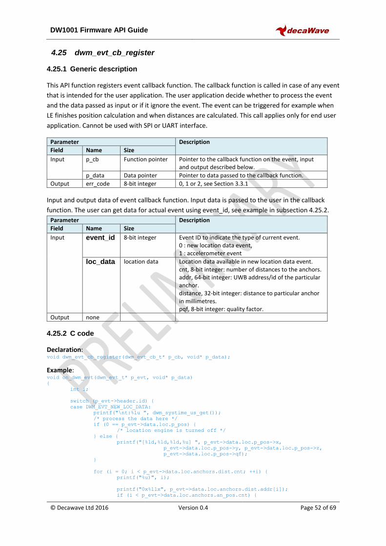
DW1001 Firmware API Guide
© Decawave Ltd 2016 Version 0.4 Page 52 of 69
4.25 dwm_evt_cb_register
4.25.1 Generic description
This API function registers event callback function. The callback function is called in case of any event
that is intended for the user application. The user application decide whether to process the event
and the data passed as input or if it ignore the event. The event can be triggered for example when
LE finishes position calculation and when distances are calculated. This call applies only for end user
application. Cannot be used with SPI or UART interface.
Parameter Description
Field Name Size
Input p_cb Function pointer Pointer to the callback function on the event, input and output described below.
p_data Data pointer Pointer to data passed to the callback function.
Output err_code 8-bit integer 0, 1 or 2, see Section 3.3.1
Input and output data of event callback function. Input data is passed to the user in the callback
function. The user can get data for actual event using event_id, see example in subsection 4.25.2.
Parameter Description
Field Name Size
Input event_id 8-bit integer Event ID to indicate the type of current event. 0 : new location data event, 1 : accelerometer event
loc_data location data Location data available in new location data event. cnt, 8-bit integer: number of distances to the anchors. addr, 64-bit integer: UWB address/id of the particular anchor. distance, 32-bit integer: distance to particular anchor in millimetres. pqf, 8-bit integer: quality factor.
Output none
4.25.2 C code
Declaration: void dwm_evt_cb_register(dwm_evt_cb_t* p_cb, void* p_data);
Example: void on_dwm_evt(dwm_evt_t* p_evt, void* p_data)
{
int i;
switch (p_evt->header.id) {
case DWM_EVT_NEW_LOC_DATA:
printf("\nt:%lu ", dwm_systime_us_get());
/* process the data here */
if (0 == p_evt->data.loc.p_pos) {
/* location engine is turned off */
} else {
printf("[%ld,%ld,%ld,%u] ", p_evt->data.loc.p_pos->x,
p_evt->data.loc.p_pos->y, p_evt->data.loc.p_pos->z,
p_evt->data.loc.p_pos->qf);
}
for (i = 0; i < p_evt->data.loc.anchors.dist.cnt; ++i) {
printf("%u)", i);
printf("0x%llx", p_evt->data.loc.anchors.dist.addr[i]);
if (i < p_evt->data.loc.anchors.an_pos.cnt) {
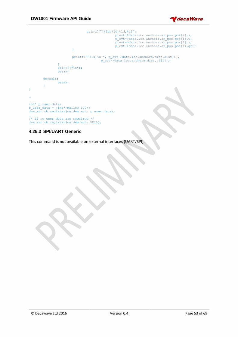
DW1001 Firmware API Guide
© Decawave Ltd 2016 Version 0.4 Page 53 of 69
printf("[%ld,%ld,%ld,%u]",
p_evt->data.loc.anchors.an_pos.pos[i].x,
p_evt->data.loc.anchors.an_pos.pos[i].y,
p_evt->data.loc.anchors.an_pos.pos[i].z,
p_evt->data.loc.anchors.an_pos.pos[i].qf);
}
printf("=%lu,%u ", p_evt->data.loc.anchors.dist.dist[i],
p_evt->data.loc.anchors.dist.qf[i]);
}
printf("\n");
break;
default:
break;
}
}
…
int* p_user_data;
p_user_data = (int*)malloc(100);
dwm_evt_cb_register(on_dwm_evt, p_user_data);
…
/* if no user data are required */
dwm_evt_cb_register(on_dwm_evt, NULL);
4.25.3 SPI/UART Generic
This command is not available on external interfaces (UART/SPI).
DW1001 Firmware API Guide
© Decawave Ltd 2016 Version 0.4 Page 54 of 69
5 SHELL COMMANDS
Shell uses UART interface which can work also in binary mode. The binary mode is used to read API
commands in TLV format. DWM starts by default in binary mode after reset. The shell mode can be
switched to by pressing ENTER twice within 1 second. The binary mode can be switched to by
executing command “quit” when in shell mode. The shell mode and the binary mode can be
switched back and forth. Press Enter in shell mode to repeat the last command. Following text
provides overview of the shell commands.
5.1 ?
Displays help.
Example: dwm> ? Usage: <command> [arg0] [arg1] Build-in commands: ** Command group: Base ** ?: this help help: this help quit: quit ** Command group: GPIO ** gc: GPIO clear gg: GPIO get gs: GPIO set gt: GPIO toggle ** Command group: SYS ** f: Show free memory on the heap ps: Show running threads pms: Show PM tasks reset: Reboot the system si: System info ut: Show device uptime ** Command group: SENS ** twi: General purpose TWI read aid: Read ACC device ID av: Read ACC values ** Command group: LE ** les: Show meas. and pos. lec: Show meas. and pos. in CSV lep: Show pos. in CSV ** Command group: UWBMAC ** nmg: Get node mode nmp: Set mode to PN (passive)
DW1001 Firmware API Guide
© Decawave Ltd 2016 Version 0.4 Page 55 of 69
nmo: Set mode to PN (off) nma: Set mode to AN nmi: Set mode to AIN nmt: Set mode to TN nmtl: Set mode to TN-LP la: Show AN list stg: Get stats stc: Clear stats ** Command group: API ** tlv: Send TLV frame aurs: Set upd rate aurg: Get upd rate apg: Get pos aps: Set pos acas: Set anchor config acts: Set tag config ** Tips ** Press Enter to repeat the last command
5.2 help
Displays help, same as command “?”.
Example: dwm> help … /*same output as command ? */
5.3 quit
Quit shell and switch UART into API mode.
Example: dwm> quit /* press enter twice to switch to shell mode again*/
5.4 gc
Clears GPIO pin. See section 3.3.3 for valid GPIO number.
Example: dwm> gc Usage: gc <pin> dwm> gc 13 gpio13: 0
5.5 gg
Reads GPIO pin level. See section 3.3.3 for valid GPIO number.
Example:
DW1001 Firmware API Guide
© Decawave Ltd 2016 Version 0.4 Page 56 of 69
dwm> gg Usage: gg <pin> dwm> gg 13 gpio13: 0
5.6 gs
Sets GPIO as output and sets its value. See section 3.3.3 for valid GPIO number.
Example: dwm> gs Usage: gs <pin> dwm> gs 13 gpio13: 1
5.7 gt
Toggles GPIO pin (must be output). See section 3.3.3 for valid GPIO number.
Example: dwm> gt Usage: gt <pin> dwm> gt 13 gpio13: 0
5.8 f
Show free memory on the heap.
Example: dwm> f [000014.560 INF] mem: free=3888 alloc=9184 tot=13072
5.9 ps
Show info about running threads.
Example: dwm> ps ID NAME PRIO STACK USED 1 idle 31 512 304 2 ser 13 768 360 3 svc 15 1024 512 4 uwb 5 2560 760 5 api 10 2048 1180 6 sd 6 1024 352 7 ble 7 1024 392 8 le 14 2048 688 9 pm 17 512 304 10 sh 16 2048 1096
DW1001 Firmware API Guide
© Decawave Ltd 2016 Version 0.4 Page 57 of 69
5.10 pms
Show power managements tasks. IDL means that task is idle. USE means that task is allocated in the power management.
Example: dwm> pms
ID NAME USE IDL ALM 0 ble 1 0 0 1 le 1 1 0 2 sh 1 0 0 3 -- 0 0 0 4 -- 0 0 0
5.11 reset
Reboot the system.
Example: dwm> reset /* node resets and boots in binary mode */
5.12 ut
Show device uptime.
Example: dwm> ut [000003.680 INF] uptime: 00:07:49.210 0 days (469210 ms)
5.13 twi
General purpose I2C/TWI read.
Example: dwm> twi
Usage: twi <addr> <reg> [bytes to read (1 or 2)]
dwm> twi 0x19 0x27 1
TWI: tx error: 33281
TWI: rx error: 33281
twi: addr=0x19, reg[0x27]=0x00
5.14 aid
Read ACC device ID
Example: dwm> aid
acc: 0x33
DW1001 Firmware API Guide
© Decawave Ltd 2016 Version 0.4 Page 58 of 69
5.15 av
Read ACC values.
Example: dwm> av
acc: x = 240, y = -3792, z = 16240
dwm> av
acc: x = 32, y = -3504, z = 15872
dwm> av
acc: x = 160, y = -3600, z = 16144
5.16 les
Show distances to ranging anchors and the position if location engine is enabled.
Example: dwm> les
1151[5.00,8.00,2.25]=6.48 0CA8[0.00,8.00,2.25]=6.51 111C[5.00,0.00,2.25]=3.18
1150[0.00,0.00,2.25]=3.16 le_us=2576 est[2.57,1.98,1.68,100]
5.17 lec
Show distances to ranging anchors and the position if location engine is enabled in CSV format.
Example: dwm> lec
DIST,4,AN0,1151,5.00,8.00,2.25,6.44,AN1,0CA8,0.00,8.00,2.25,6.50,AN2,111C,5.00,0.00,2.25,3.24,A
N3,1150,0.00,0.00,2.25,3.19,POS,2.55,2.01,1.71,98
5.18 lep
Show position in CSV format.
Example: dwm> lep
POS,2.57,2.00,1.67,97
5.19 si
System info
Example: dwm> si
[000077.340 INF] cfg:
[000077.340 INF] >fw1=x00022000
[000077.340 INF] board=DM1_A1
[000077.340 INF] cfg_ver=x00010500
[000077.350 INF] fw_ver=x01010200
DW1001 Firmware API Guide
© Decawave Ltd 2016 Version 0.4 Page 59 of 69
[000077.350 INF] hw_ver=xDE410100
[000077.350 INF] opt=x03C10900
[000077.360 INF] fw_size[0]=x0001F000
[000077.360 INF] fw_size[1]=x0002F000
[000077.360 INF] fw_size[2]=x0002F000
[000077.370 INF] fw_csum[0]=x9445F89E
[000077.370 INF] fw_csum[1]=xF49DBF2A
[000077.370 INF] fw_csum[2]=xEB65F61F
[000077.380 INF] opt: LEDS LP UWB0 BLE I2C SPI UART
[000077.380 INF] mcu: temp=29.2 hfclk=rc:on lfclk=xtal:on
[000077.390 INF] uptime: 00:01:17.390 0 days (77390 ms)
[000077.390 INF] mem: free=2128 alloc=7224 tot=9352
[000077.400 INF] uwb: ch5 prf64 plen128 pac8 txcode9 rxcode9 sfd0 baud1
[000077.410 INF] uwb: tx_pwr=xC0/x25456585 125:250:500:norm[ms]=17:14:]
[000077.410 INF] uwb0: lna=0 xtaltrim=15 tx_delay=16472 rx_delay=16472
[000077.420 INF] uwb0: ID dev=xDECA0130 part=x1000113B lot=x10205EE9
[000077.430 INF] uwb0: panid=x0000 addr=xDECA7B1782D0113B
[000077.430 INF] mode: tn (act,twr,lp,nole)
[000077.440 INF] uwbmac: disconnected
[000077.440 INF] tn: upd_per=100000 upd_per_stat=100000 us
[000077.440 INF] tn: cnt=0 rtc:hrclk:devt dri=0.000000:0.000000:0.00000
5.20 nmg
Get node mode info.
Example: dwm> nmg
mode: tn (act,twr,np,nole)
5.21 nmo
Enable passive offline option and resets the node.
Example: dwm> nmo
/* press enter twice to switch to shell mode after reset*/
DWM1001 TWR Real Time Location System
Copyright : 2016-2017 LEAPS and Decawave
License : Please visit https://decawave.com/dwm1001_license
Compiled : Jul 3 2017 12:33:40
Help : ? or help
DW1001 Firmware API Guide
© Decawave Ltd 2016 Version 0.4 Page 60 of 69
dwm> nmg
mode: tn (off,twr,np,nole)
5.22 nmp
Enable active offline option and resets the node.
Example: dwm> nmp
/* press enter twice to switch to shell mode after reset*/
DWM1001 TWR Real Time Location System
Copyright : 2016-2017 LEAPS and Decawave
License : Please visit https://decawave.com/dwm1001_license
Compiled : Jul 3 2017 12:33:40
Help : ? or help
dwm> nmg
mode: tn (pasv,twr,np,nole)
5.23 nma
Configures node to as anchor, active and reset the node.
Example: dwm> nma
/* press Enter twice */
DWM1001 TWR Real Time Location System
Copyright : 2016-2017 LEAPS and Decawave
License : Please visit https://decawave.com/dwm1001_license
Compiled : Jul 3 2017 12:33:40
Help : ? or help
dwm> nmg
mode: an (act,-,-)
DW1001 Firmware API Guide
© Decawave Ltd 2016 Version 0.4 Page 61 of 69
5.24 nmi
Configures node to as anchor - initiator, active and reset the node.
Example: dwm> nmi
/* press enter twice */
DWM1001 TWR Real Time Location System
Copyright : 2016-2017 LEAPS and Decawave
License : Please visit https://decawave.com/dwm1001_license
Compiled : Jul 3 2017 12:33:40
Help : ? or help
dwm> nmg
mode: ain (act,real,-)
5.25 nmt
Configures node to as tag, active and reset the node.
Example: dwm> nmt
/* press enter twice */
DWM1001 TWR Real Time Location System
Copyright : 2016-2017 LEAPS and Decawave
License : Please visit https://decawave.com/dwm1001_license
Compiled : Jul 3 2017 12:33:40
Help : ? or help
dwm> nmg
mode: tn (act,twr,np,le)
5.26 nmtl
Configures node to as tag, active, low power and resets the node.
DW1001 Firmware API Guide
© Decawave Ltd 2016 Version 0.4 Page 62 of 69
Example: dwm> nmtl
/* press enter twice */
DWM1001 TWR Real Time Location System
Copyright : 2016-2017 LEAPS and Decawave
License : Please visit https://decawave.com/dwm1001_license
Compiled : Jul 3 2017 12:33:40
Help : ? or help
dwm> nmg
mode: tn (act,twr,lp,le)
5.27 la
Show anchor list.
Example: dwm> la
[003452.590 INF] AN: cnt=4 seq=x03
[003452.590 INF] 0) id=DECA5419E2E01151 seat=0 idl=0 seens=0 col=0 cl=000F nbr=000F fl=4002
opt=03C1B046 hw=DE41010
0 fw=01010101 fwc=7B033F01
[003452.600 INF] 1) id=DECA78A55EB00CA8 seat=1 idl=1 seens=119 col=0 cl=000F nbr=0000
fl=0000 opt=03C1B042 hw=DE410
100 fw=01010101 fwc=7B033F01
[003452.620 INF] 2) id=DECAFCED8D50111C seat=2 idl=1 seens=103 col=0 cl=000F nbr=0000
fl=0000 opt=03C1B042 hw=DE410
100 fw=01010101 fwc=7B033F01
[003452.640 INF] 3) id=DECA51421A901150 seat=3 idl=0 seens=81 col=0 cl=000F nbr=0000 fl=0000
opt=03C1B042 hw=DE4101
00 fw=01010101 fwc=7B033F01
5.28 stg
Displays statistics.
Example: dwm> stg
uptime: 0
memfree: 0
DW1001 Firmware API Guide
© Decawave Ltd 2016 Version 0.4 Page 63 of 69
mcu_temp: 0
rtc_drift: 0.000000
ble_con_ok: 0
ble_dis_ok: 0
ble_err: 0
uwb0_intr: 0
uwb0_rst: 0
rx_ok: 56454
rx_err: 0
tx_err: 0
tx_errx: 0
bcn_tx_ok: 1661
bcn_tx_err: 0
bcn_rx_ok: 0
alma_tx_ok: 51
alma_tx_err: 0
alma_rx_ok: 0
cl_tx_ok: 0
cl_tx_err: 0
cl_rx_ok: 0
cl_coll: 0
fwup_tx_ok: 0
fwup_tx_err: 0
fwup_rx_ok: 0
svc_tx_ok: 0
svc_tx_err: 0
svc_rx_ok: 0
clk_sync: 0
twr_ok: 0
twr_err: 0
res[0]: 0
res[1]: 0
res[2]: 0
res[3]: 0
res[4]: 0
res[5]: 0
res[6]: 0
res[7]: 0
tot_err: 0
5.29 stc
Clears statistics.
DW1001 Firmware API Guide
© Decawave Ltd 2016 Version 0.4 Page 64 of 69
Example: dwm> stc
5.30 tlv
Parses given TLV frame. See Section 4 for valid TLV commands.
Example: read node configuration dwm> tlv 8 0
OUTPUT FRAME:
40 01 00 46 02 b0 00
Example: toggles GPIO pin 13 dwm> tlv 44 1 13
OUTPUT FRAME:
40 01 00
5.31 aurs
Set position update rate. See section 4.3 for more detail.
Example: dwm> aurs
Usage aurs <ur> <urs>
dwm> aurs 10 20
err code: 0
5.32 aurg
Get position update rate. See section 4.4 for more detail.
Example: dwm> aurg
err code: 0, upd rate: 10, 20(stat)
5.33 apg
Get position of the node. See section 3.3.2 for more detail.
Example: dwm> apg
x:100 y:120 z:2500 qf:100
5.34 aps
Set position of the node. See section 3.3.2 for more detail.
DW1001 Firmware API Guide
© Decawave Ltd 2016 Version 0.4 Page 65 of 69
Example: dwm> aps
Usage aps <x> <y> <z>
dwm> aps 100 120 2500
err code: 0
5.35 acas
Configures node as anchor with given options. See section 3.3.8 for more detail. Note that this
command only sets the configuration parameters. To make effect of the settings, users should issue
s reset command, see section 5.11 for more detail.
Example: dwm> acas
Usage acas <inr> <bridge> <leds> <ble> <uwb> <fw_upd>
dwm> acas 0 0 1 1 2 0
err code: 0
5.36 acts
Configures node as tag with given options. See section 3.3.7 for more detail. Note that this
command only sets the configuration parameters. To make effect of the settings, users should issue
s reset command, see section 5.11 for more detail.
Example: dwm> acts
Usage acts <meas_mode> <accel_en> <low_pwr> <loc_en> <leds> <ble> <uwb> <fw_upd>
dwm> acts 0 1 0 1 1 0 0 0
err code: 0
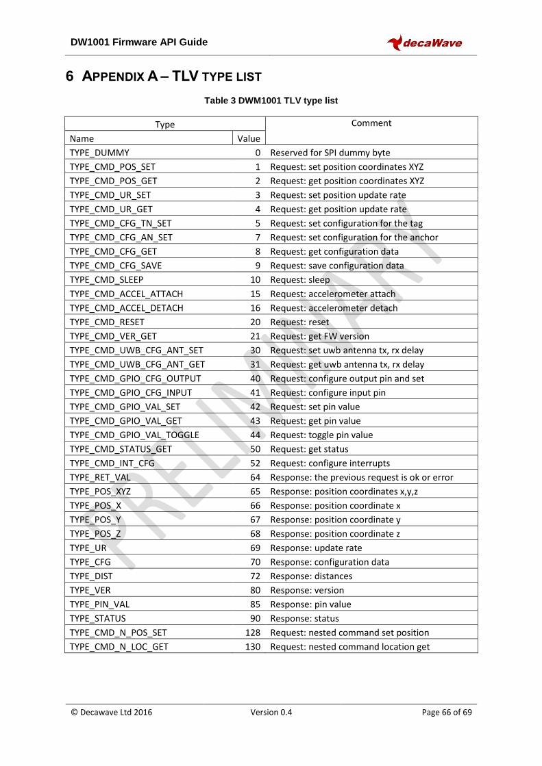
DW1001 Firmware API Guide
© Decawave Ltd 2016 Version 0.4 Page 66 of 69
6 APPENDIX A – TLV TYPE LIST
Table 3 DWM1001 TLV type list
Type Comment
Name Value
TYPE_DUMMY 0 Reserved for SPI dummy byte
TYPE_CMD_POS_SET 1 Request: set position coordinates XYZ
TYPE_CMD_POS_GET 2 Request: get position coordinates XYZ
TYPE_CMD_UR_SET 3 Request: set position update rate
TYPE_CMD_UR_GET 4 Request: get position update rate
TYPE_CMD_CFG_TN_SET 5 Request: set configuration for the tag
TYPE_CMD_CFG_AN_SET 7 Request: set configuration for the anchor
TYPE_CMD_CFG_GET 8 Request: get configuration data
TYPE_CMD_CFG_SAVE 9 Request: save configuration data
TYPE_CMD_SLEEP 10 Request: sleep
TYPE_CMD_ACCEL_ATTACH 15 Request: accelerometer attach
TYPE_CMD_ACCEL_DETACH 16 Request: accelerometer detach
TYPE_CMD_RESET 20 Request: reset
TYPE_CMD_VER_GET 21 Request: get FW version
TYPE_CMD_UWB_CFG_ANT_SET 30 Request: set uwb antenna tx, rx delay
TYPE_CMD_UWB_CFG_ANT_GET 31 Request: get uwb antenna tx, rx delay
TYPE_CMD_GPIO_CFG_OUTPUT 40 Request: configure output pin and set
TYPE_CMD_GPIO_CFG_INPUT 41 Request: configure input pin
TYPE_CMD_GPIO_VAL_SET 42 Request: set pin value
TYPE_CMD_GPIO_VAL_GET 43 Request: get pin value
TYPE_CMD_GPIO_VAL_TOGGLE 44 Request: toggle pin value
TYPE_CMD_STATUS_GET 50 Request: get status
TYPE_CMD_INT_CFG 52 Request: configure interrupts
TYPE_RET_VAL 64 Response: the previous request is ok or error
TYPE_POS_XYZ 65 Response: position coordinates x,y,z
TYPE_POS_X 66 Response: position coordinate x
TYPE_POS_Y 67 Response: position coordinate y
TYPE_POS_Z 68 Response: position coordinate z
TYPE_UR 69 Response: update rate
TYPE_CFG 70 Response: configuration data
TYPE_DIST 72 Response: distances
TYPE_VER 80 Response: version
TYPE_PIN_VAL 85 Response: pin value
TYPE_STATUS 90 Response: status
TYPE_CMD_N_POS_SET 128 Request: nested command set position
TYPE_CMD_N_LOC_GET 130 Request: nested command location get
DW1001 Firmware API Guide
© Decawave Ltd 2016 Version 0.4 Page 67 of 69
7 APPENDIX B – BIBLIOGRAPHY
1. nRF5 Getting Started , Available from
https://infocenter.nordicsemi.com/index.jsp?topic=%2Fcom.nordic.infocenter.sdk52.v0.9.2
%2Findex.html
2. IEEE 802.15.4‐2011 or “IEEE Std 802.15.4™‐2011” (Revision of IEEE Std 802.15.4-2006). IEEE
Standard for Local and metropolitan area networks— Part 15.4: Low-Rate Wireless Personal
Area Networks (LR-WPANs). IEEE Computer Society Sponsored by the LAN/MAN Standards
Committee. Available from http://standards.ieee.org/
3. DWM1001 Firmware User Guide
Available from \\svn\Software\Products\Argo\Argo-Firmware-User-Guide.docx
4. DWM1001 System Guide – to guide users how to build the RTLS system with multiple
DWM1001 modules.
https://infocenter.nordicsemi.com/index.jsp?topic=%2Fcom.nordic.infocenter.sdk52.v0.9.2%2Findex.html
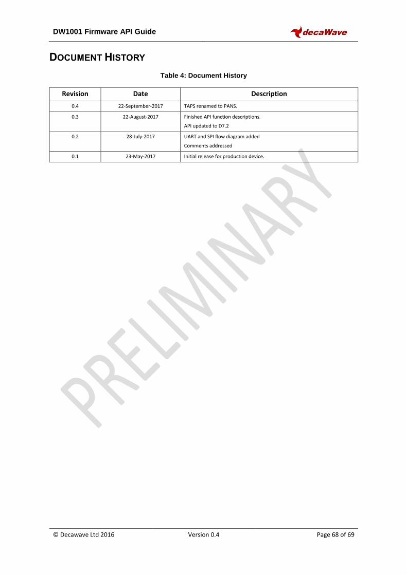
DW1001 Firmware API Guide
© Decawave Ltd 2016 Version 0.4 Page 68 of 69
DOCUMENT HISTORY
Table 4: Document History
Revision Date Description
0.4 22-September-2017 TAPS renamed to PANS.
0.3 22-August-2017 Finished API function descriptions.
API updated to D7.2
0.2 28-July-2017 UART and SPI flow diagram added
Comments addressed
0.1 23-May-2017 Initial release for production device.
DW1001 Firmware API Guide
© Decawave Ltd 2016 Version 0.4 Page 69 of 69
8 ABOUT DECAWAVE
Decawave is a pioneering fabless semiconductor company whose flagship product, the DW1000, is a
complete, single chip CMOS Ultra-Wideband IC based on the IEEE 802.15.4 standard UWB PHY. This
device is the first in a family of parts.
The resulting silicon has a wide range of standards-based applications for both Real Time Location
Systems (RTLS) and Ultra Low Power Wireless Transceivers in areas as diverse as manufacturing,
healthcare, lighting, security, transport, and inventory and supply-chain management.
For further information on this or any other Decawave product contact a sales representative as
follows: -
Decawave Ltd,
Adelaide Chambers,
Peter Street,
Dublin 8,
Ireland.
mailto:[email protected]
http://www.decawave.com/


![DWM1001 Product Brief[1][1] · · 2018-03-28• 嵌入式 DRTLS 固件 (DWM1001 TWR RTLS) 减少软件开发工作 • 定制嵌入式用户应用程序的固件 API • 通过外部设备访问](https://static.fdocuments.net/doc/165x107/5b03a36b7f8b9a2d518c7488/dwm1001-product-brief11-drtls-dwm1001-twr-rtls-.jpg)