DW718 – Mitre Saw - 2helpU – Mitre Saw. go to: ... bevel and detent plates Rpm, Clamp Washer,...
38
go to: INDEX - PREVIOUS - NEXT DW718 EUROPEAN SERVICE REPAIR TRAINING DW718 – Mitre Saw
Transcript of DW718 – Mitre Saw - 2helpU – Mitre Saw. go to: ... bevel and detent plates Rpm, Clamp Washer,...

go to:
INDEX - PREVIOUS - NEXTDW718
EUROPEAN SERVICE REPAIR TRAINING
DW718 – Mitre Saw
go to:
INDEX - PREVIOUS - NEXTDW718
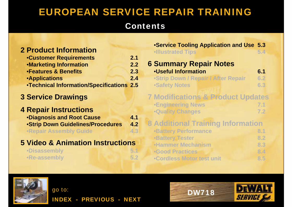
•Service Tooling Application and Use 5.3•Illustrated Tips 5.4
6 Summary Repair Notes•Useful Information 6.1•Strip Down / Repair / After Repair 6.2•Safety Notes 6.3
7 Modifications & Product Updates•Engineering News 7.1•Quality Changes 7.2
8 Additional Training Information•Battery Performance 8.1•Battery Tester 8.2•Hammer Mechanism 8.3•Good Practices 8.4•Cordless Motor test unit 8.5
EUROPEAN SERVICE REPAIR TRAINING
2 Product Information•Customer Requirements 2.1•Marketing Information 2.2•Features & Benefits 2.3•Applications 2.4•Technical Information/Specifications 2.5
3 Service Drawings
4 Repair Instructions•Diagnosis and Root Cause 4.1•Strip Down Guidelines/Procedures 4.2•Repair Assembly Guide 4.3
5 Video & Animation Instructions•Disassembly 5.1•Re-assembly 5.2
Contents
go to:
INDEX - PREVIOUS - NEXTDW718
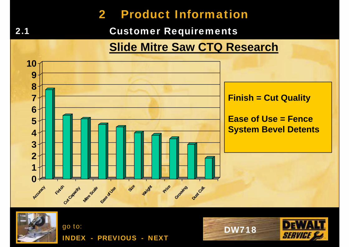
2 Product InformationCustomer Requirements2.1
Slide Mitre Saw CTQ Research
Finish = Cut Quality
Ease of Use = Fence System Bevel Detents
0123456789
10
Accur
acy
Finish
Cut Cap
acity
Mitre S
cale
Ease
of U
se Size
Weight
Price
Groov
ing
Dust C
oll.

go to:
INDEX - PREVIOUS - NEXTDW718
2 Product InformationMarketing Information2.2
DW718-QSDW718-GBDW718-LX
DW718V-QSDW718V-GBDW718V-LX
DW718-B4DW718-XE
V indicates factory fitted laser systemDW708 WILL BE DISCONTINUED FROM AUGUST 2005

go to:
INDEX - PREVIOUS - NEXTDW718
2 Product InformationMarketing Information2.2
DW718 - 305mm Compound Slide Mitre Saw
•Cam action mitre lock function makes mitre setting faster and easier allowing the user to quickly adjust angles between 0° - 60° left and 0° - 50° right•The innovative grooving stop allows the adjustment of the cutting depth for grooving and rebating applications.•The large dual sliding fence gives maximum support in large material cuts at any angle or combination of angles.•Linear horizontal rails utilise bronze guides to provide maximum precision when cutting materials up to 345mm wide.•New quick release bevel setting provides accurate and simple setting of bevel angles up to 48° left and right.•Compact and lightweight design characteristics deliver a saw with enormous capacity which is easy to transport around the jobsite
go to:
INDEX - PREVIOUS - NEXTDW718
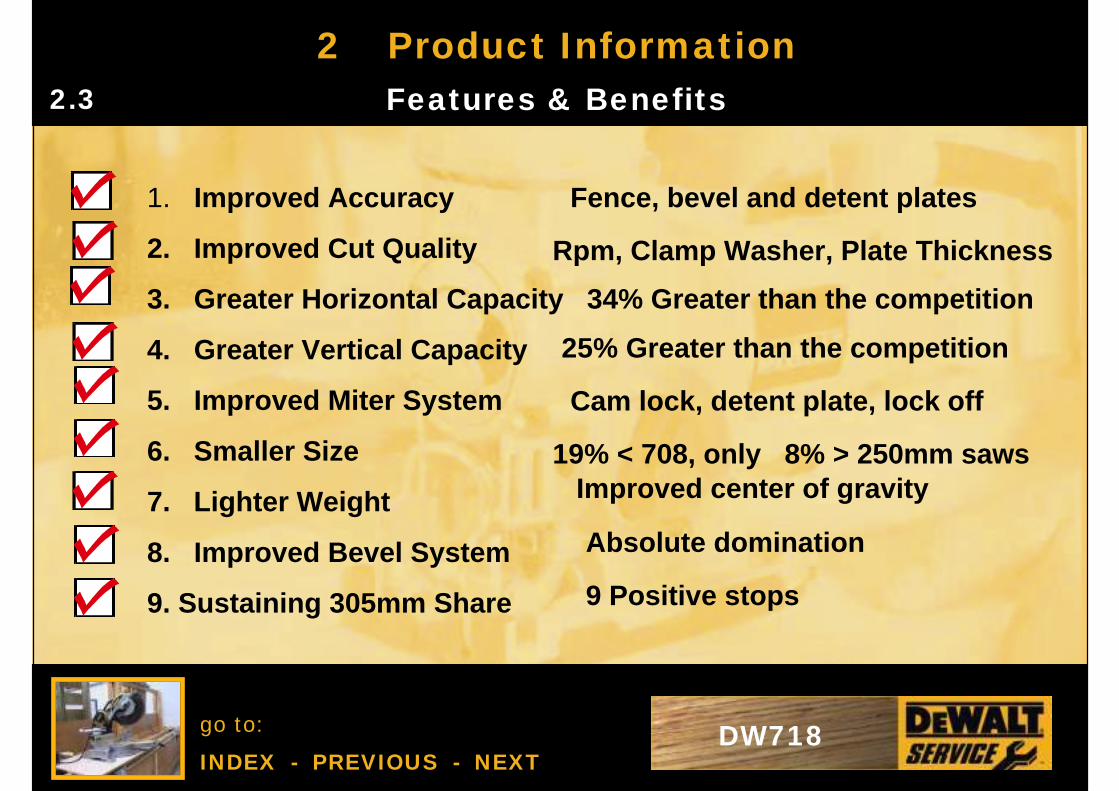
2 Product InformationFeatures & Benefits2.3
1. Improved Accuracy
2. Improved Cut Quality
3. Greater Horizontal Capacity 34% Greater than the competition
4. Greater Vertical Capacity
5. Improved Miter System
6. Smaller Size
7. Lighter Weight
8. Improved Bevel System
9. Sustaining 305mm Share
Fence, bevel and detent plates
Rpm, Clamp Washer, Plate Thickness
25% Greater than the competition
19% < 708, only 8% > 250mm sawsImproved center of gravity
9 Positive stops
Absolute domination
Cam lock, detent plate, lock off
go to:
INDEX - PREVIOUS - NEXTDW718
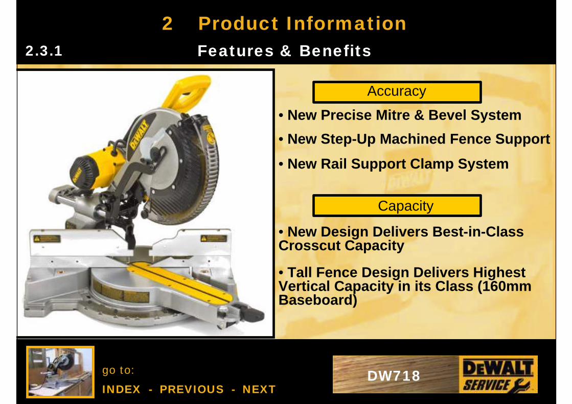
2 Product InformationFeatures & Benefits2.3.1
Accuracy
• New Precise Mitre & Bevel System
• New Step-Up Machined Fence Support
• New Rail Support Clamp System
Capacity
• New Design Delivers Best-in-Class Crosscut Capacity
• Tall Fence Design Delivers Highest Vertical Capacity in its Class (160mm Baseboard)
DW718
go to:
INDEX - PREVIOUS - NEXTDW718
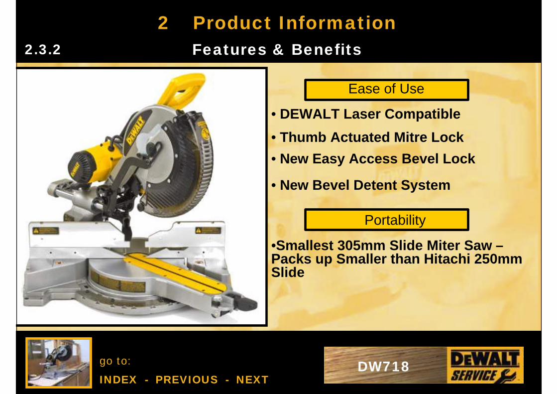
2 Product InformationFeatures & Benefits2.3.2
Ease of Use
Portability
DW718
• Thumb Actuated Mitre Lock
• New Easy Access Bevel Lock
• New Bevel Detent System
• DEWALT Laser Compatible
•Smallest 305mm Slide Miter Saw –Packs up Smaller than Hitachi 250mm Slide
go to:
INDEX - PREVIOUS - NEXTDW718
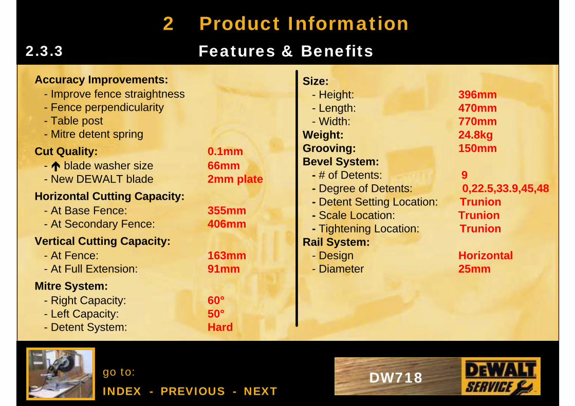
2 Product InformationFeatures & Benefits2.3.3
Accuracy Improvements:- Improve fence straightness- Fence perpendicularity- Table post- Mitre detent spring
Cut Quality: 0.1mm- é blade washer size 66mm- New DEWALT blade 2mm plate
Horizontal Cutting Capacity:- At Base Fence: 355mm - At Secondary Fence: 406mm
Vertical Cutting Capacity: - At Fence: 163mm - At Full Extension: 91mm
Mitre System: - Right Capacity: 60°- Left Capacity: 50°- Detent System: Hard
Size: - Height: 396mm - Length: 470mm - Width: 770mm
Weight: 24.8kgGrooving: 150mm Bevel System:
- # of Detents: 9 - Degree of Detents: 0,22.5,33.9,45,48- Detent Setting Location: Trunion- Scale Location: Trunion- Tightening Location: Trunion
Rail System:- Design Horizontal - Diameter 25mm
go to:
INDEX - PREVIOUS - NEXTDW718
2 Product InformationApplications2.4
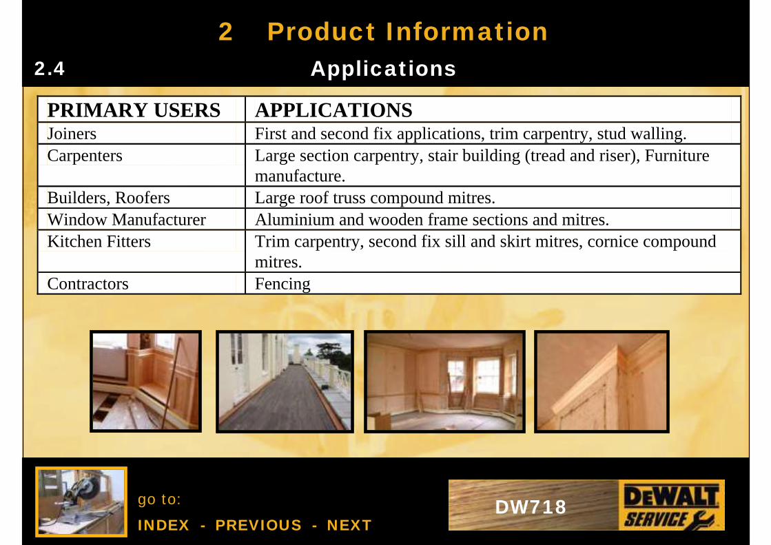
PRIMARY USERS APPLICATIONS Joiners First and second fix applications, trim carpentry, stud walling. Carpenters Large section carpentry, stair building (tread and riser), Furniture
manufacture. Builders, Roofers Large roof truss compound mitres. Window Manufacturer Aluminium and wooden frame sections and mitres. Kitchen Fitters Trim carpentry, second fix sill and skirt mitres, cornice compound
mitres. Contractors Fencing
go to:
INDEX - PREVIOUS - NEXTDW718
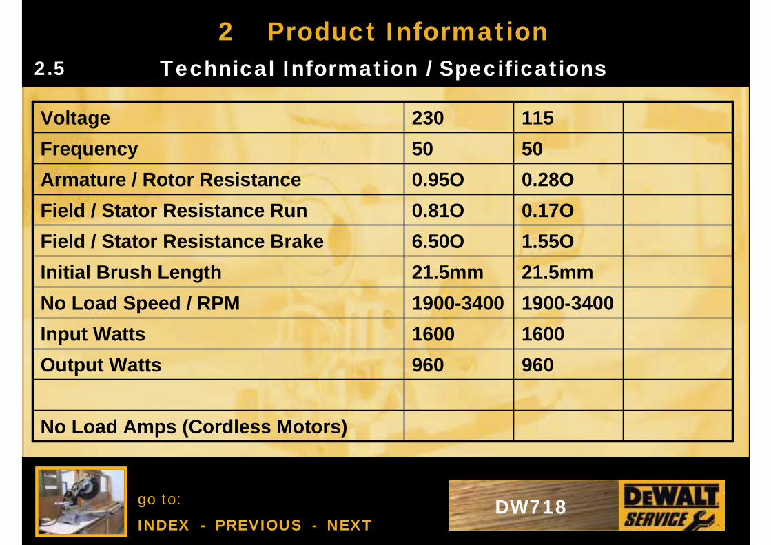
2 Product InformationTechnical Information / Specifications2.5
No Load Amps (Cordless Motors)
960960Output Watts
16001600Input Watts
1900-34001900-3400No Load Speed / RPM
21.5mm21.5mmInitial Brush Length
1.55O6.50OField / Stator Resistance Brake
0.17O0.81OField / Stator Resistance Run
0.28O0.95OArmature / Rotor Resistance
5050Frequency
115230Voltage
go to:
INDEX - PREVIOUS - NEXTDW718
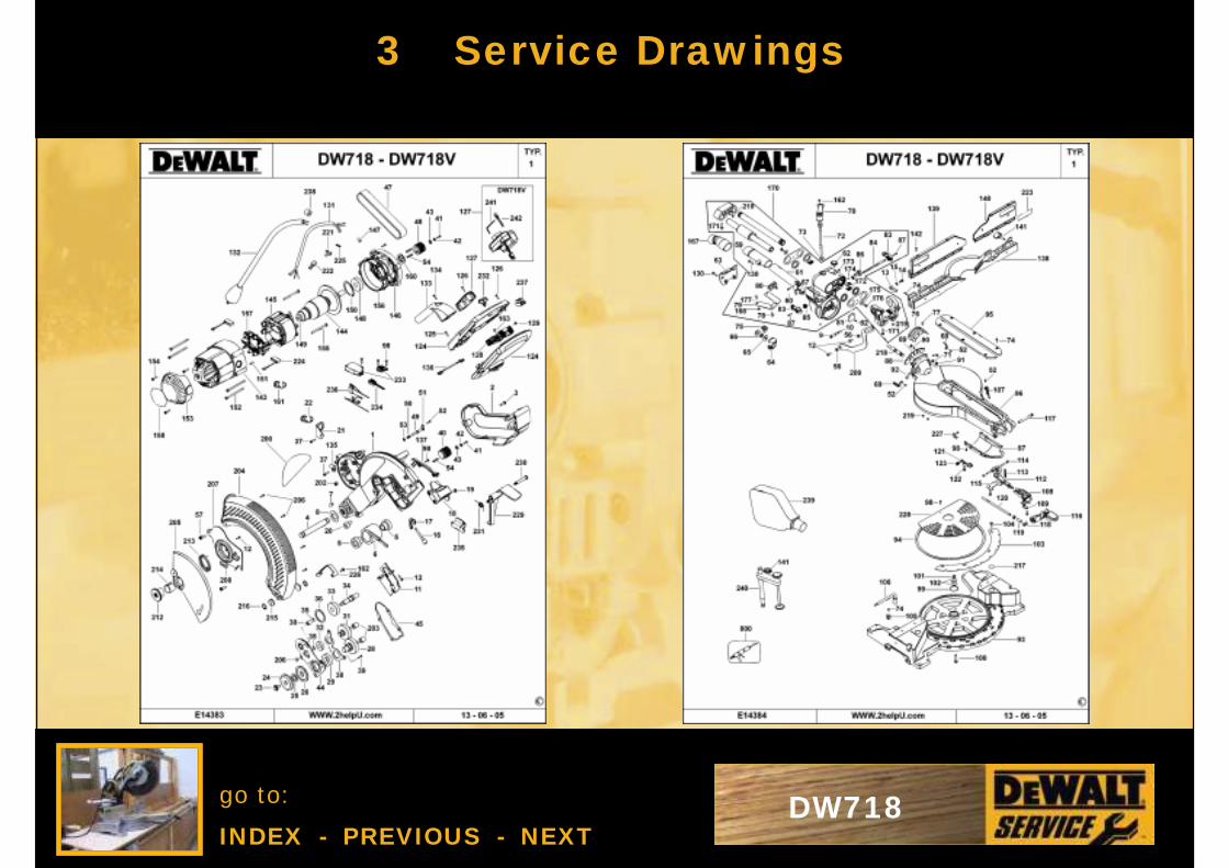
3 Service Drawings
go to:
INDEX - PREVIOUS - NEXTDW718
3 Service Drawings
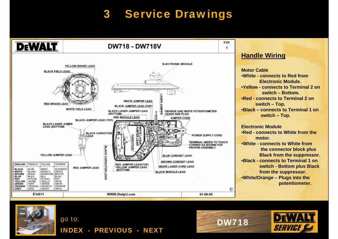
Handle Wiring
Motor Cable•White - connects to Red from
Electronic Module.•Yellow - connects to Terminal 2 on
switch – Bottom.•Red - connects to Terminal 2 on
switch – Top.•Black – connects to Terminal 1 on
switch – Top.
Electronic Module•Red - connects to White from the
motor.•White - connects to White from
the connector block plusBlack from the suppressor.
•Black - connects to Terminal 1 onswitch - Bottom plus Blackfrom the suppressor.
•White/Orange – Plugs into thepotentiometer.
go to:
INDEX - PREVIOUS - NEXTDW718
4 Repair InstructionsDiagnosis and Root Cause4.1
DiagnosisCheck the unit is not plugged in
• Check Cable• Check whether blade is tight• Check condition of blade• Check condition of drive belt• Check guard operation
Plug unit in• Quick test and check all functions• Make a test cut• Check for accuracy
go to:
INDEX - PREVIOUS - NEXTDW718
4 Repair InstructionsStrip Down Guidelines / Procedures4.2
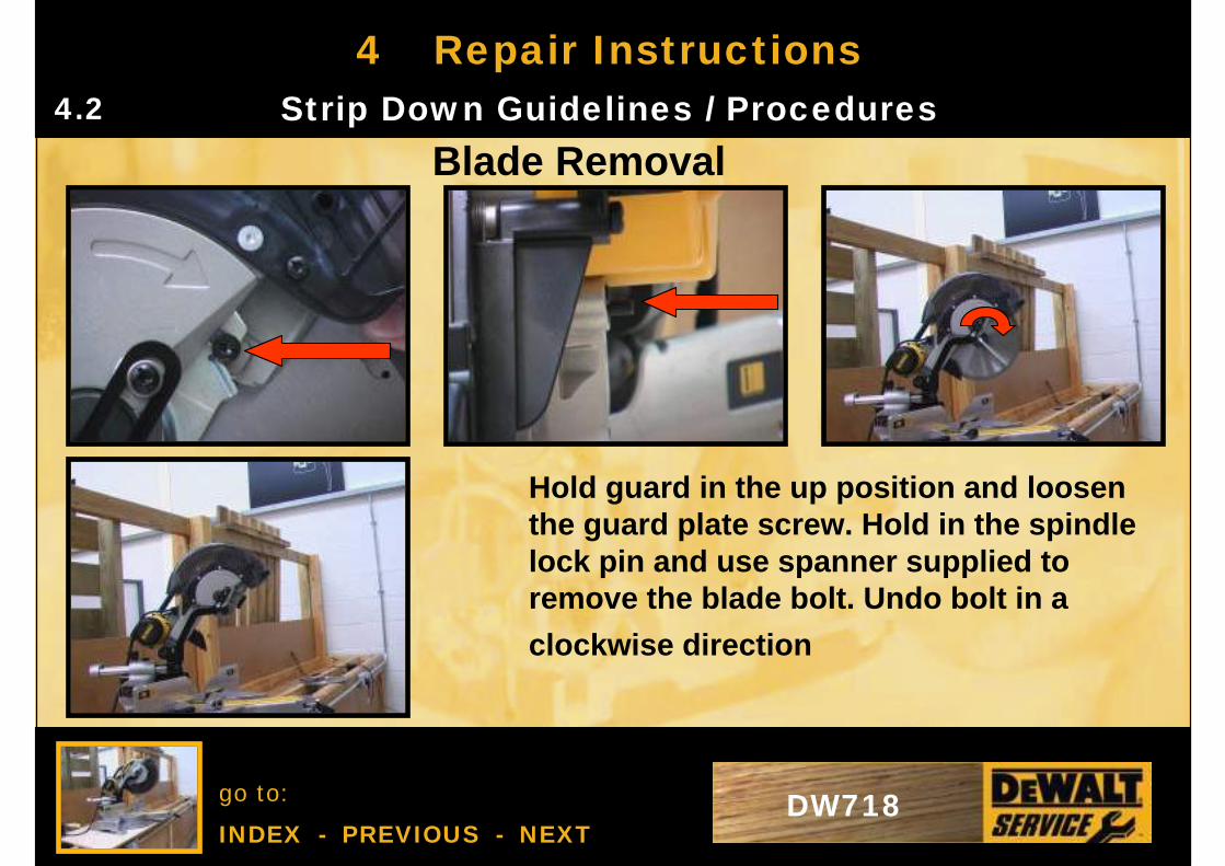
Blade Removal
Hold guard in the up position and loosen the guard plate screw. Hold in the spindle lock pin and use spanner supplied to remove the blade bolt. Undo bolt in a
clockwise direction
go to:
INDEX - PREVIOUS - NEXTDW718
4 Repair InstructionsStrip Down Guidelines / Procedures4.2.1
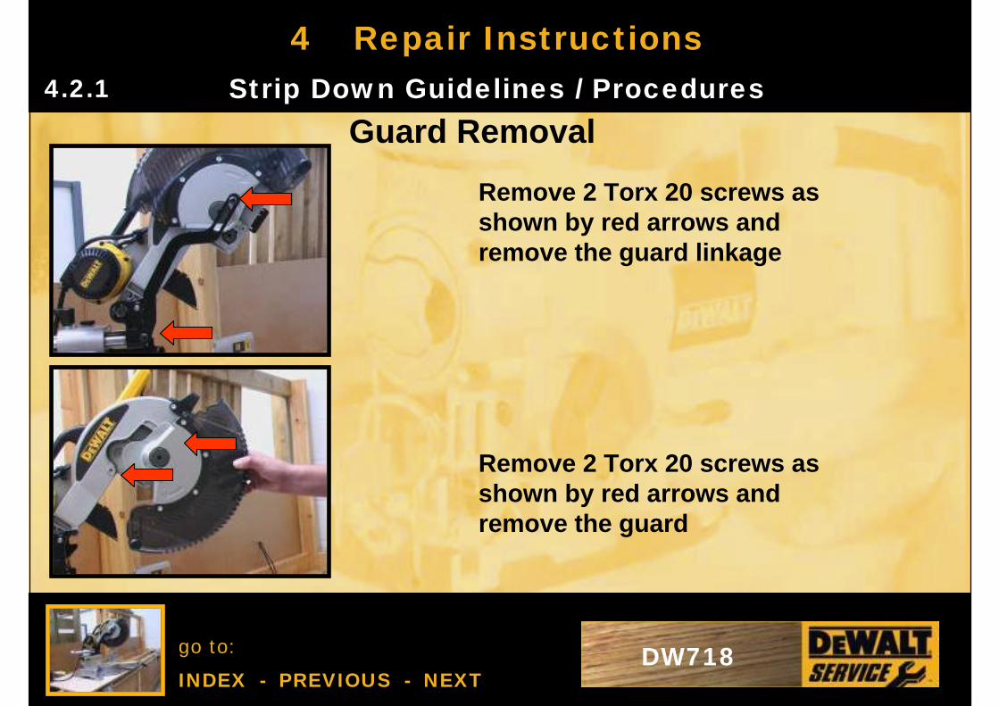
Guard Removal
Remove 2 Torx 20 screws as shown by red arrows and remove the guard linkage
Remove 2 Torx 20 screws as shown by red arrows and remove the guard
go to:
INDEX - PREVIOUS - NEXTDW718
4 Repair InstructionsStrip Down Guidelines / Procedures4.2.2
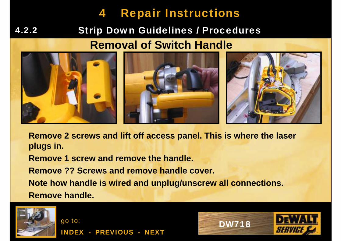
Removal of Switch Handle
Remove 2 screws and lift off access panel. This is where the laser plugs in.Remove 1 screw and remove the handle.Remove ?? Screws and remove handle cover.Note how handle is wired and unplug/unscrew all connections.Remove handle.
go to:
INDEX - PREVIOUS - NEXTDW718
4 Repair InstructionsStrip Down Guidelines / Procedures4.2.3
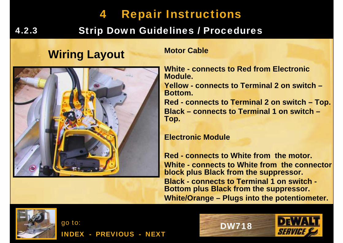
Wiring Layout Motor Cable
White - connects to Red from Electronic Module.Yellow - connects to Terminal 2 on switch –Bottom.Red - connects to Terminal 2 on switch – Top.Black – connects to Terminal 1 on switch –Top.
Electronic Module
Red - connects to White from the motor.White - connects to White from the connector block plus Black from the suppressor.Black - connects to Terminal 1 on switch -Bottom plus Black from the suppressor.White/Orange – Plugs into the potentiometer.
go to:
INDEX - PREVIOUS - NEXTDW718
4 Repair InstructionsStrip Down Guidelines / Procedures4.2.4
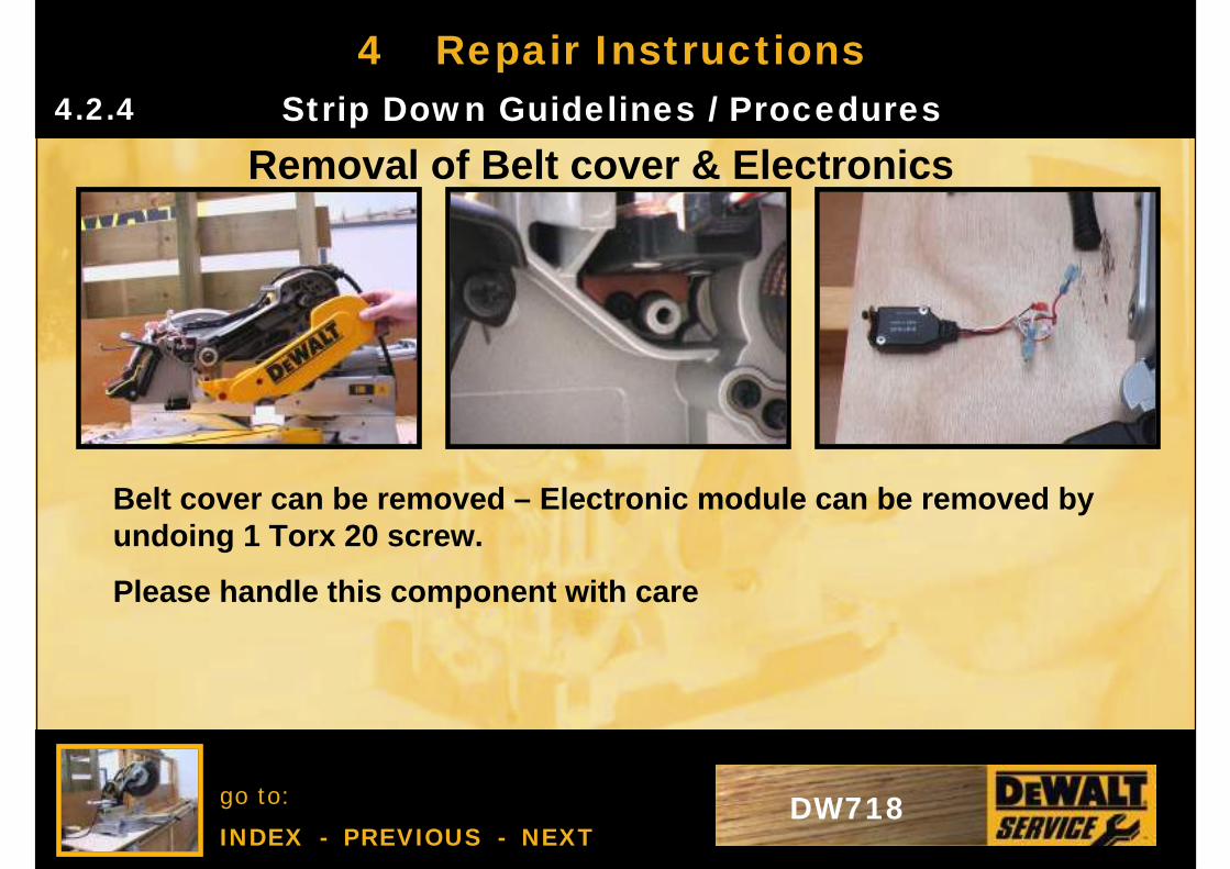
Removal of Belt cover & Electronics
Belt cover can be removed – Electronic module can be removed by undoing 1 Torx 20 screw.
Please handle this component with care
go to:
INDEX - PREVIOUS - NEXTDW718
4 Repair InstructionsStrip Down Guidelines / Procedures4.2.5
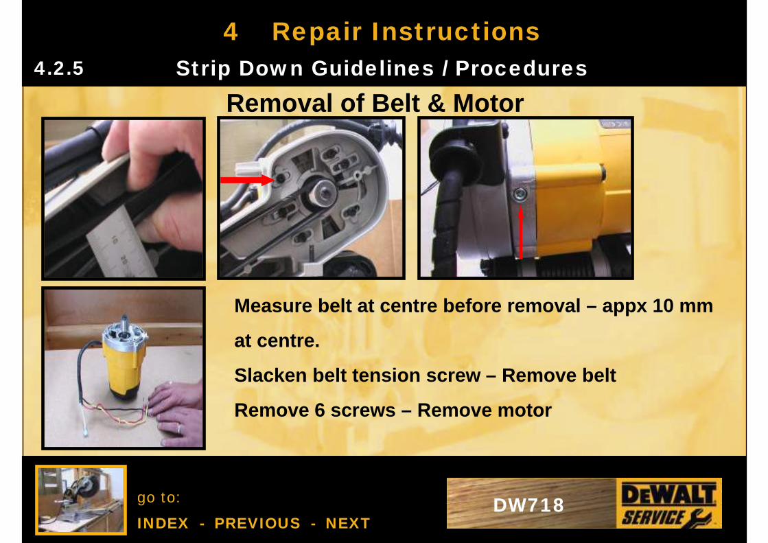
Removal of Belt & Motor
Measure belt at centre before removal – appx 10 mm
at centre.
Slacken belt tension screw – Remove belt
Remove 6 screws – Remove motor
go to:
INDEX - PREVIOUS - NEXTDW718
4 Repair InstructionsStrip Down Guidelines / Procedures4.2.6
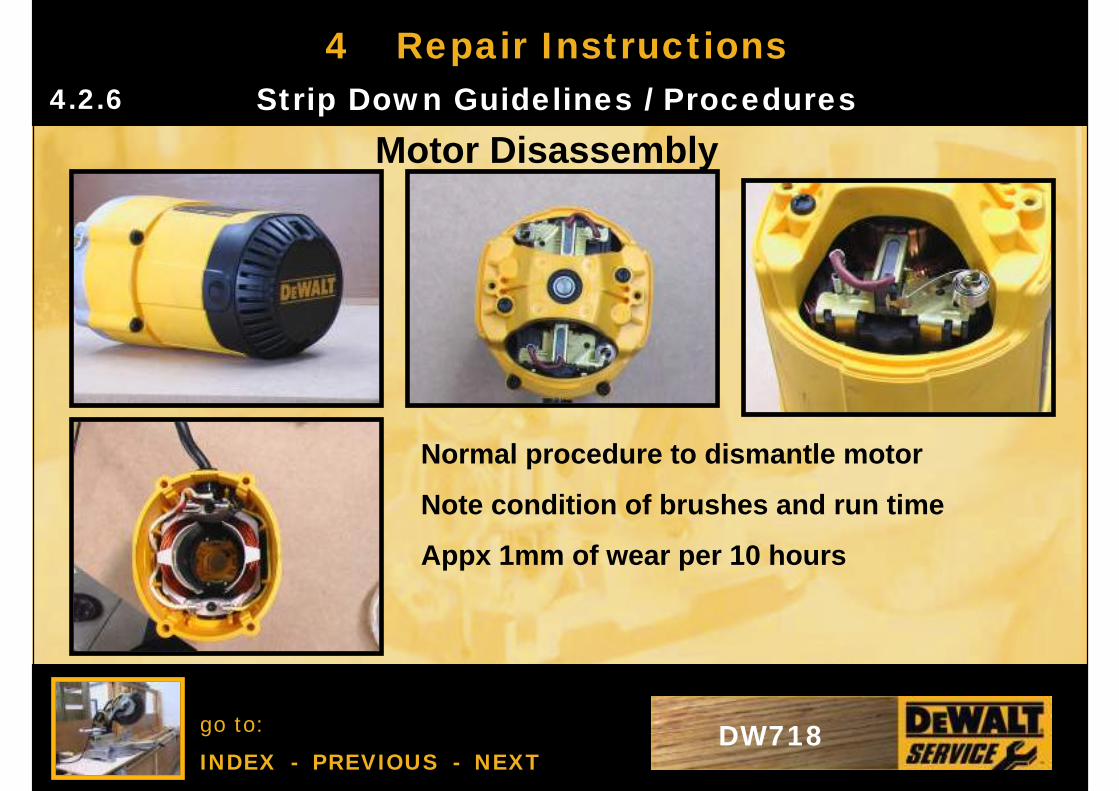
Motor Disassembly
Normal procedure to dismantle motor
Note condition of brushes and run time
Appx 1mm of wear per 10 hours
go to:
INDEX - PREVIOUS - NEXTDW718
4 Repair InstructionsStrip Down Guidelines / Procedures4.2.7
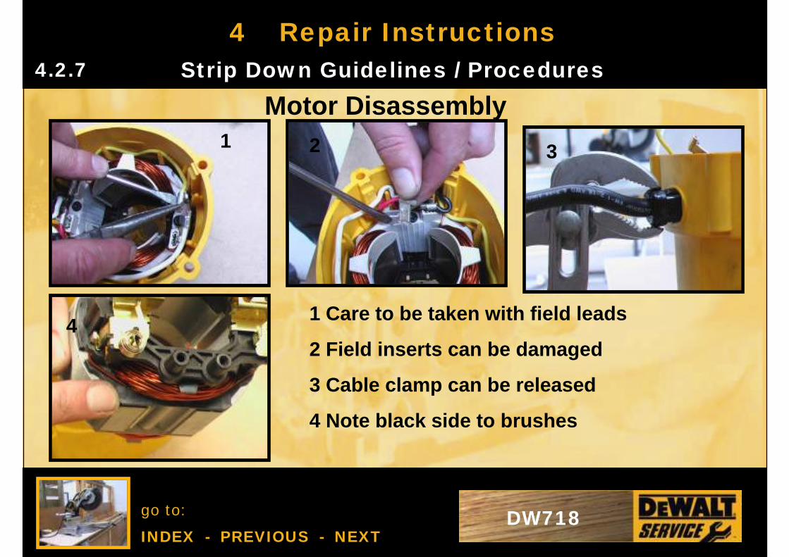
Motor Disassembly
1 Care to be taken with field leads
2 Field inserts can be damaged
3 Cable clamp can be released
4 Note black side to brushes
1 2 3
4
go to:
INDEX - PREVIOUS - NEXTDW718
4 Repair InstructionsStrip Down Guidelines / Procedures4.2.8
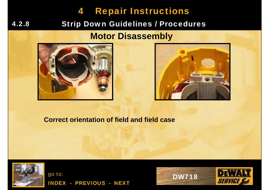
Motor Disassembly
Correct orientation of field and field case
go to:
INDEX - PREVIOUS - NEXTDW718
4 Repair InstructionsStrip Down Guidelines / Procedures4.2.9
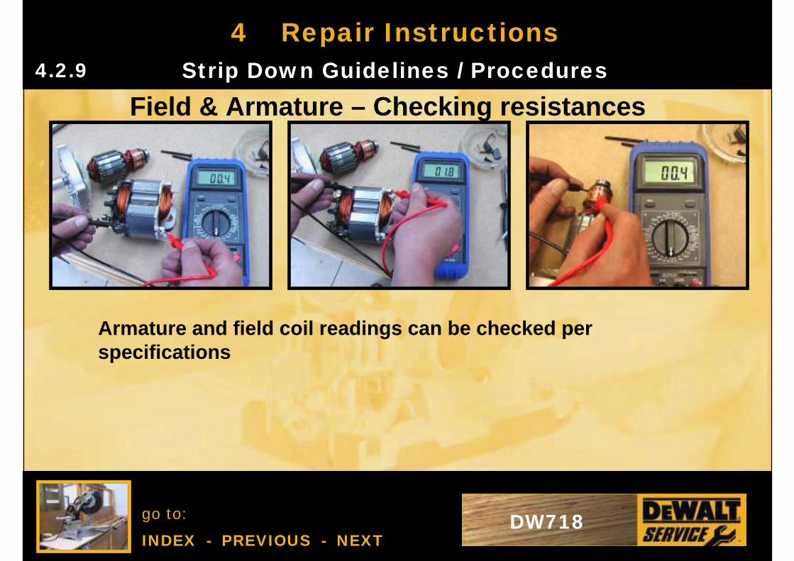
Field & Armature – Checking resistances
Armature and field coil readings can be checked per specifications
go to:
INDEX - PREVIOUS - NEXTDW718
4 Repair InstructionsStrip Down Guidelines / Procedures4.2.10
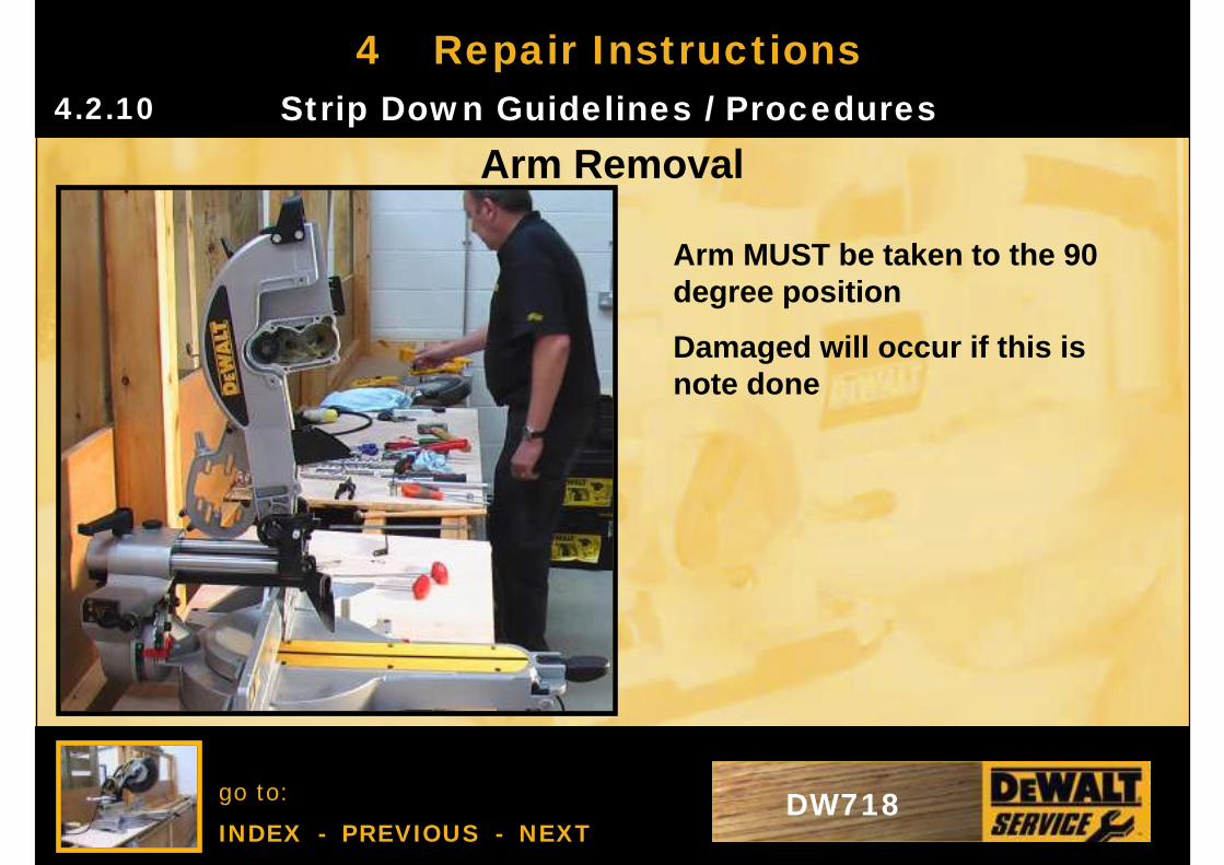
Arm Removal
Arm MUST be taken to the 90 degree position
Damaged will occur if this is note done
go to:
INDEX - PREVIOUS - NEXTDW718
4 Repair InstructionsStrip Down Guidelines / Procedures4.2.11
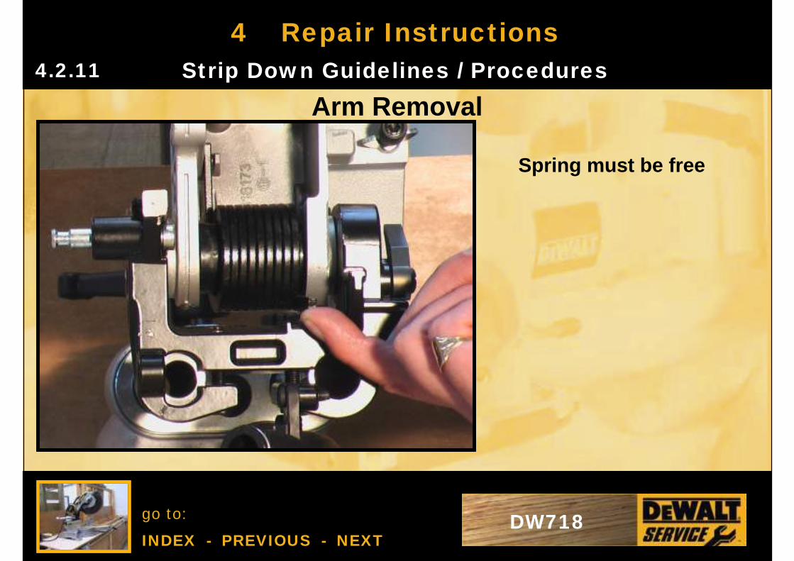
Arm Removal
Spring must be free
go to:
INDEX - PREVIOUS - NEXTDW718
4 Repair InstructionsStrip Down Guidelines / Procedures4.2.12
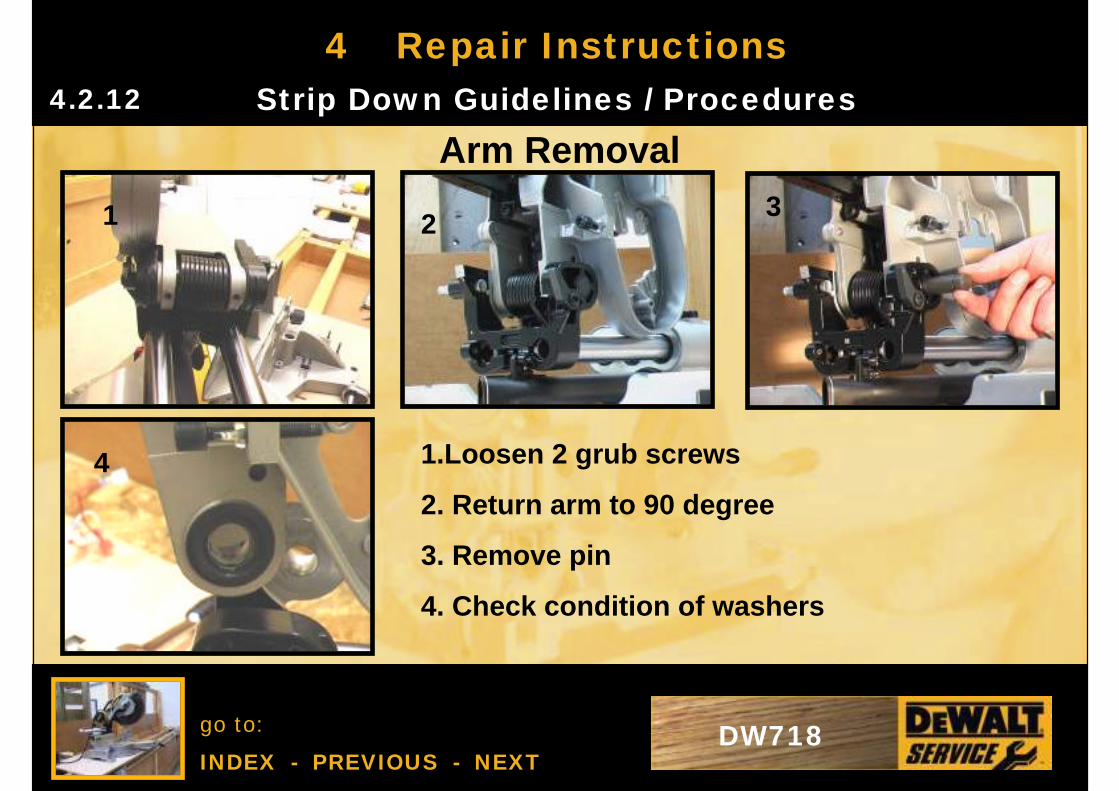
Arm Removal
1 23
4 1.Loosen 2 grub screws
2. Return arm to 90 degree
3. Remove pin
4. Check condition of washers
go to:
INDEX - PREVIOUS - NEXTDW718
4 Repair Instructions
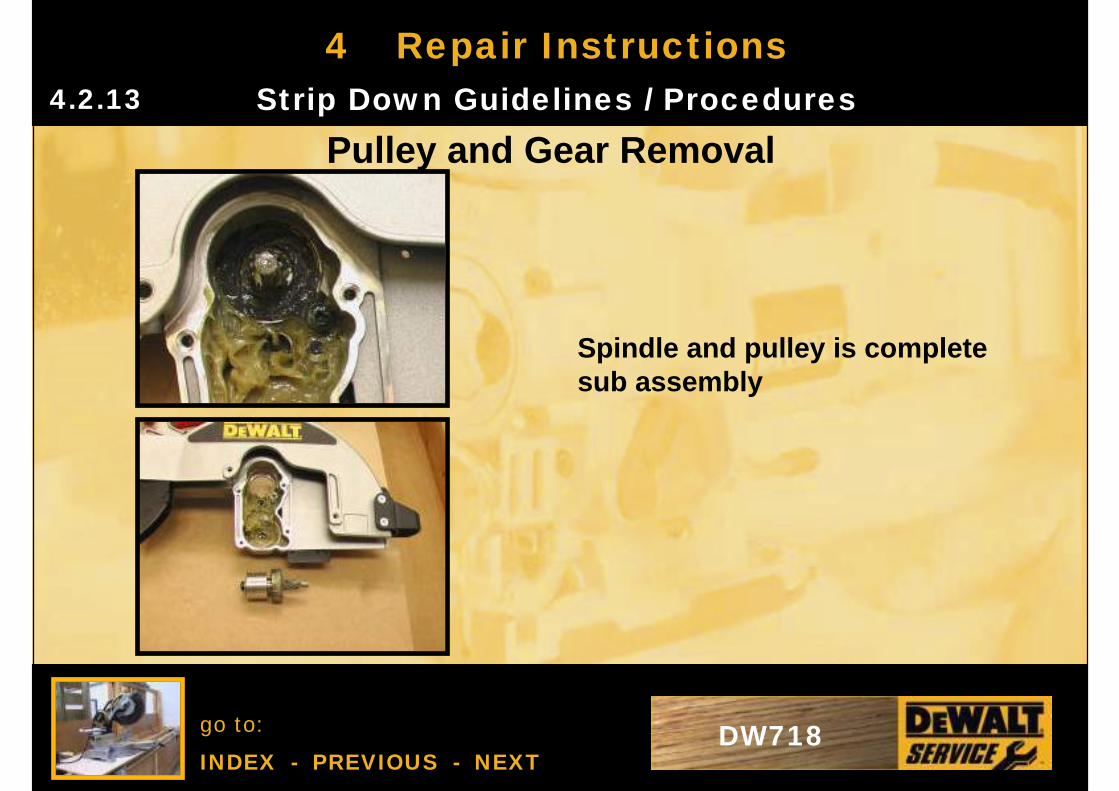
Spindle and pulley is complete sub assembly
Strip Down Guidelines / Procedures4.2.13
Pulley and Gear Removal
go to:
INDEX - PREVIOUS - NEXTDW718
4 Repair InstructionsStrip Down Guidelines / Procedures4.2.14
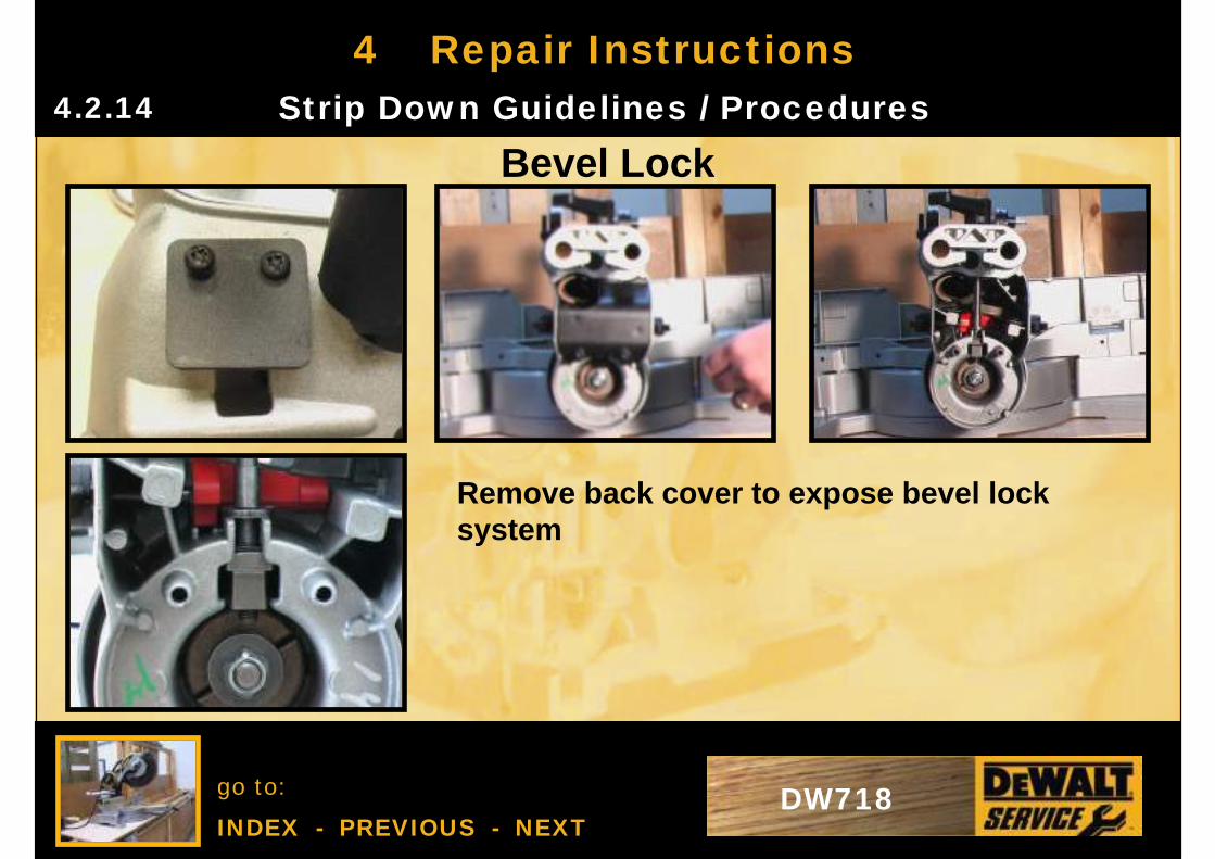
Bevel Lock
Remove back cover to expose bevel lock system
go to:
INDEX - PREVIOUS - NEXTDW718
4 Repair InstructionsStrip Down Guidelines / Procedures4.2.15
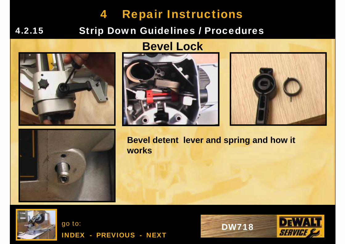
Bevel Lock
Bevel detent lever and spring and how it works
go to:
INDEX - PREVIOUS - NEXTDW718
4 Repair InstructionsStrip Down Guidelines / Procedures4.2.16
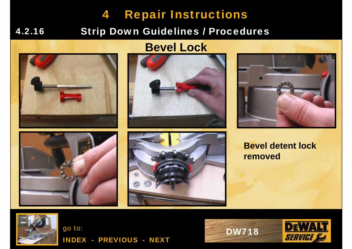
Bevel Lock
Bevel detent lock removed
go to:
INDEX - PREVIOUS - NEXTDW718
4 Repair InstructionsStrip Down Guidelines / Procedures4.2.17
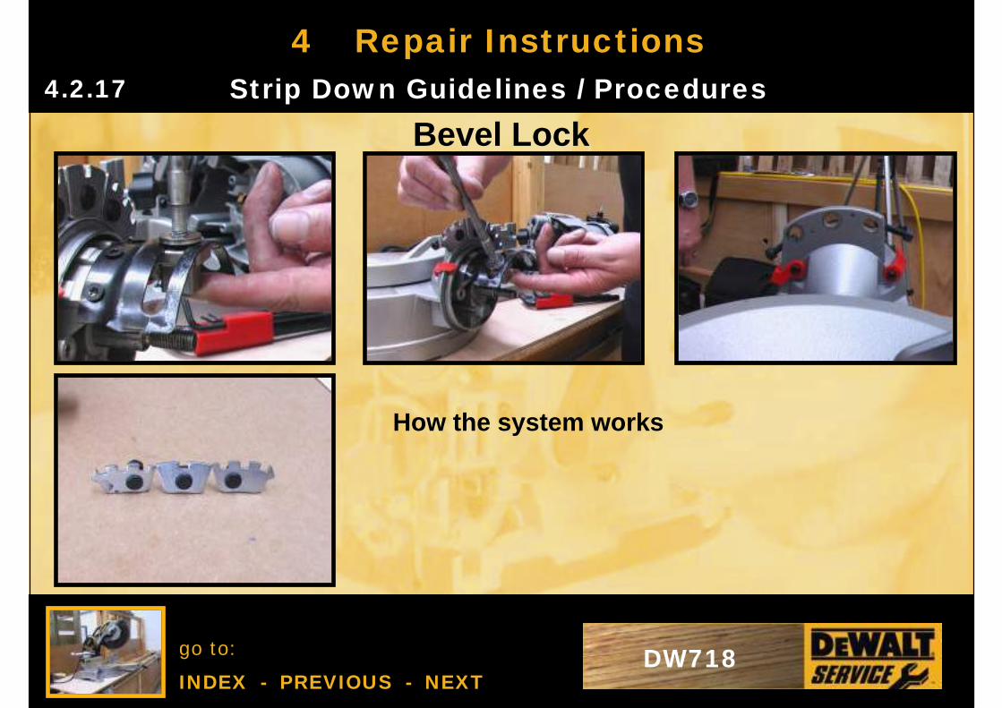
Bevel Lock
How the system works
go to:
INDEX - PREVIOUS - NEXTDW718
4 Repair InstructionsStrip Down Guidelines / Procedures4.2.18
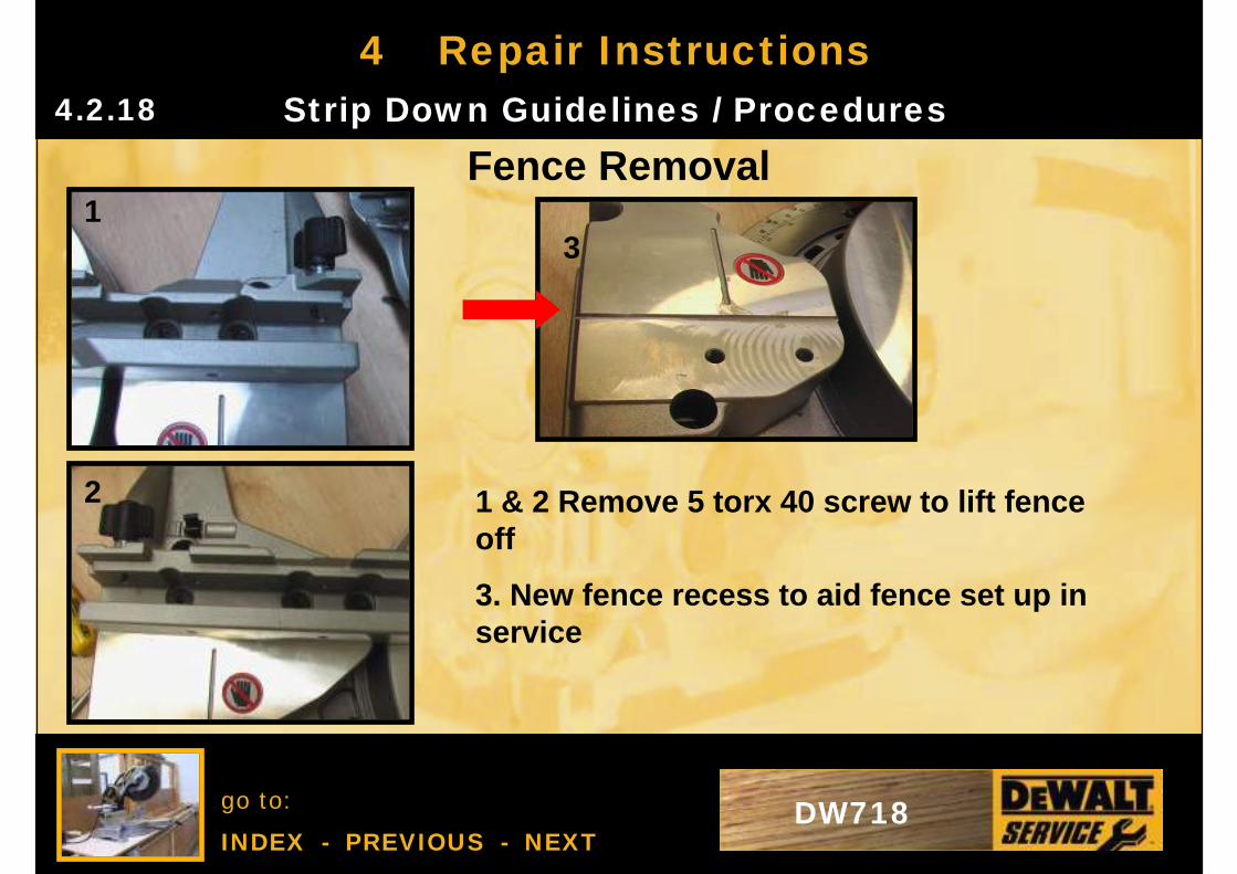
Fence Removal1
2
3
1 & 2 Remove 5 torx 40 screw to lift fence off
3. New fence recess to aid fence set up in service
go to:
INDEX - PREVIOUS - NEXTDW718
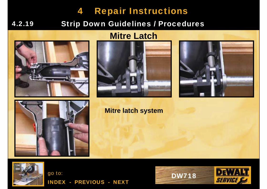
4 Repair InstructionsStrip Down Guidelines / Procedures4.2.19
Mitre Latch
Mitre latch system
go to:
INDEX - PREVIOUS - NEXTDW718
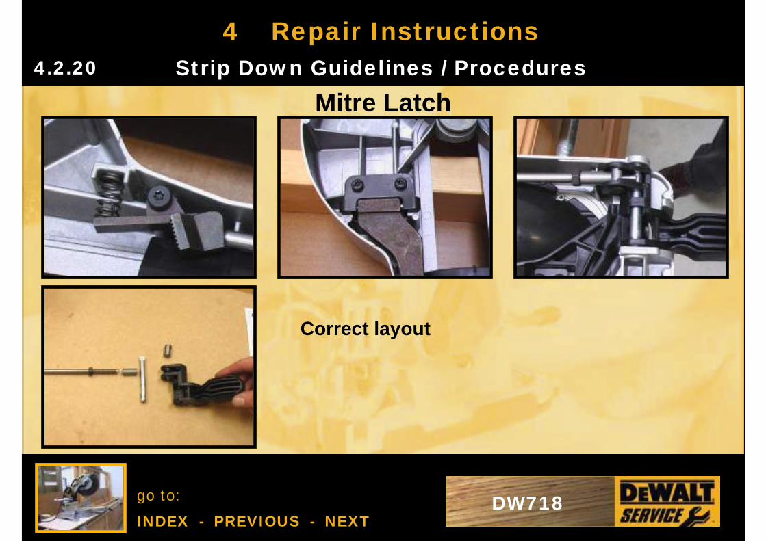
4 Repair InstructionsStrip Down Guidelines / Procedures4.2.20
Mitre Latch
Correct layout
go to:
INDEX - PREVIOUS - NEXTDW718
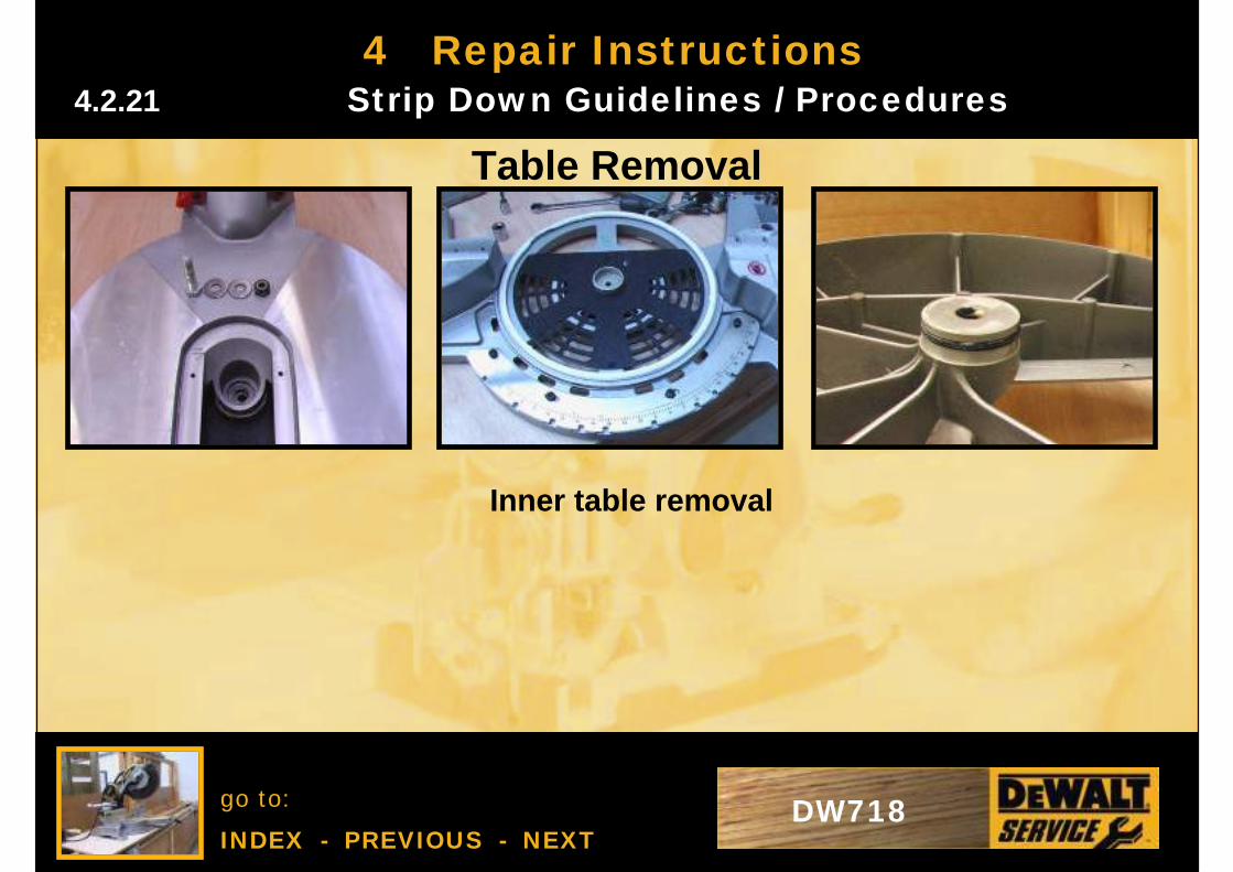
4 Repair Instructions
Table Removal
Inner table removal
4.2.21 Strip Down Guidelines / Procedures
go to:
INDEX - PREVIOUS - NEXTDW718
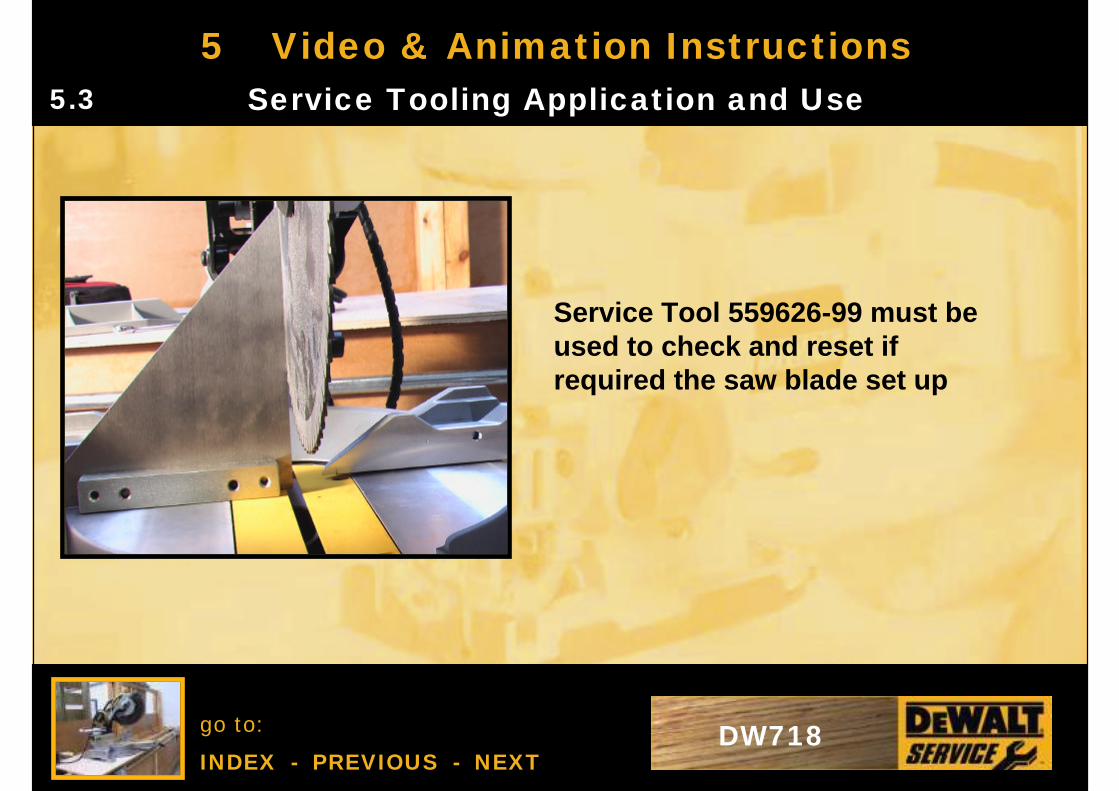
5 Video & Animation InstructionsService Tooling Application and Use5.3
Service Tool 559626-99 must be used to check and reset if required the saw blade set up
go to:
INDEX - PREVIOUS - NEXTDW718
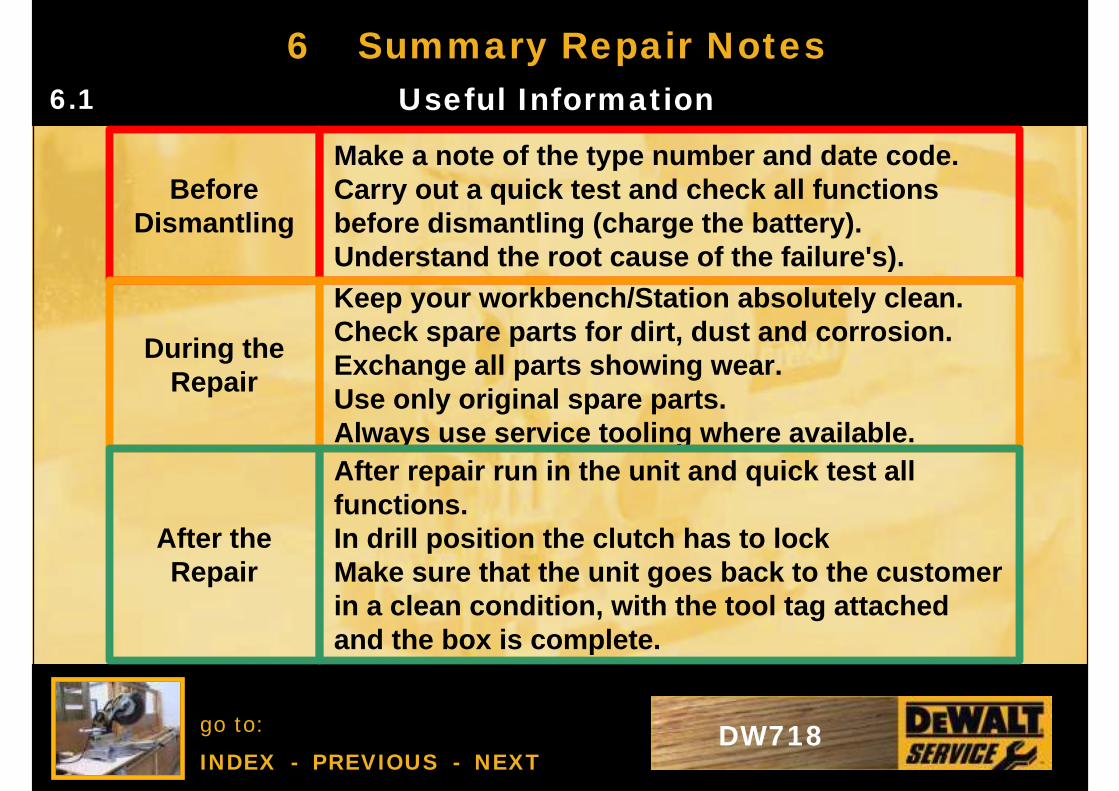
Make a note of the type number and date code.Carry out a quick test and check all functions before dismantling (charge the battery). Understand the root cause of the failure's).
Before Dismantling
6 Summary Repair NotesUseful Information6.1
Keep your workbench/Station absolutely clean.Check spare parts for dirt, dust and corrosion. Exchange all parts showing wear.Use only original spare parts.Always use service tooling where available.
During the Repair
After repair run in the unit and quick test all functions. In drill position the clutch has to lock Make sure that the unit goes back to the customer in a clean condition, with the tool tag attached and the box is complete.
After the Repair