
DVNCED LSER BSED INERTIL INSTRUENT SEILER RESEARCH LAB ... · 1707 2005 2303 clock,, injection...
21
RD-A66 387 DVNCED LSER BSED INERTIL INSTRUENT DEVELOPMENT 1 I6 (U) FRANK J SEILER RESEARCH LAB UNITED STATES AIR FORCE USI FE ACADEMY CO J R ROTBE' 1986 FJSRL-TR-86-U6@i FO07 N
Transcript of DVNCED LSER BSED INERTIL INSTRUENT SEILER RESEARCH LAB ... · 1707 2005 2303 clock,, injection...
RD-A66 387 DVNCED LSER BSED INERTIL INSTRUENT DEVELOPMENT 1
I6 (U) FRANK J SEILER RESEARCH LAB UNITED STATES AIR FORCE
USI FE ACADEMY CO J R ROTBE' 1986 FJSRL-TR-86-U6@i FO07 N
q.
Wt,
111.0L.2 I 2.2_
III2
"1i.. L.6
- -
-- C MICnROPY RESO' ITION TEST CHART
4
,.., .
%
_ * IIL ,,' -,',."L." .-. .- .. ,- ._', ", ',, ".,".," , • "- -. - .- - .... - --.-. ... .- - • . - -.. .

FRANK J1. SEILER RESEARCH LABORATORY
FJSPL-TR-S-0 r ~ MAPH)P
(0 API'ANCFP LASEP PAWE TIPTTAL
TtlSTRtlffNT PFVFLOPMFtMT
DTICFIMAL PFPOPT ELECTE
APR 7 B6,
LL. MAJOPl 7TMS P. PflTCF'
U- APPROVED FOR PUBLIC RELEASE;
DISTRIBUTION UNLIMITED.
PPOJFCT ?3ri-FI-71
AIR FORCE SYSTEMS COMMAND
UNITED STATES AIR FORCE
~6 4 o75
FJSRL-TR-86-0001
This document was prepared ty the Guidance and Control Division,
Directorate of Lasers and AercspAce Mechanics, Frank J. Seiler Research
Laboratory, United States Air Eorc, Academy, CI-orado Springs, CO. The* research was conducted under Pr( i... Work Unit Number 2301-FI-71, Advanced: Laser Based Inertial Instrument I), , i)pment (ALBIID). Major Salvatore R.
*:, Balsamo and Major James R. Rotge' were the Project Scientists in charge of the
* work.
When U.S. Government drawings, specifications or other data are used for .
any purpose other than a definitely related government procurement operation,
the government thereby incurs no responsibility nor any obligation whatsoever,
and the fact that the government may have formulated, furnished or in any way
supplied the said drawings, specifications or other data is not to be regarded
by implication or otherwise, as in any manner licensing the holder or any
other person or corporation or conveying any rights or permission to
manufacture, use or sell any patented invention that may in any way be related
thereto.
Inquiries concerning the technical content of this document should be
add;essed to the Frank J. Seiler Research Laboratory (AFSC), FJSRL/NH, USAF
Academy, Colorado Springs, CO 80840-6528. Phone AC 303-472-3122.
-This report h,,.. been reviewed by the Commander and is released to the
National Technical Information Service (NTIS). At NTIS it will be availableto the general public, including foreign nations.
This technical report has been reviewed and is approved for publication. .
>MES R. ROTGE', MajorASAF AIBERT J."AIEXADER, Major, USAF
troject Scientist Director, Lasers & Aerospace Mechanics
OlIN H. PLETCHER, JR., Col, USAFommander
Copies of this report should not he returned unless return is required bysecurity considerations, contractual obligations, or notice on a specific
document.
Printed in the United States of America. Qualified requesters may obtain
additional copies from the Defense Technical Information Center. All others
should apply to: National Technical Information Service
6285 Port Royal Road
Springfield, Virginia 22161
r
UNCLASSIFIED______SECURITY CLASSIFICATION OF THIS PAGE
REPORT DOCUMENTATION PAGE
is REPORT SECURITY CLASSIFICATION lb. RESTRICTIVE MARKINGS
UNCLASSIFIED
2. SECURITY CLASSIFICATION AUTHORITY 3. DISTRIBUTION/AVAILABILITY OF REPORT
,LA T G SC ,E ,Approved for public release;2b. OECLASIF#CATION/DOwNGRAOINGSCHEDULE Distribution unlimited
4 PERFORMING ORGANIZATION REPORT NUMBER(S) 5. MONITORING ORGANIZATION REPORT NUMBER(S)
FJSRL-TR-86-0001
6o NAME OF PERFORMING ORGANIZATION 6b. OFFICE SYMBOL 7s. NAME OF MONITORING ORGANIZATION
Frank J. Seiler Research IIfapplicable.
Laboratory FJSRL/NHG6c, ADDRESS (City. State and ZIP CodeI 7b. ADDRESS (Cit). State and ZIP Code)
USAF AcademyColorado Springs, CO 80840-6528
as NAME OF FUNDING/SPONSORING Bb. OFFICE SYMBOL 9. PROCUREMENT INSTRUMENT IDENTIFICATION NUMBERORGANIZATION (Itapp"icab.e)
8c ADDRESS (Cily. State and ZIP Cod') 10. SOURCE OF FUNDING NOS.
PROGRAM PROJECT TASK WORK UNITELEMENT NO. NO. NO. NO.
I TITLE ,include Security Cta.f,,ation, Advanced Laser Based 61102F 2301 Fl 71
Inertia] Instrument Developmont (U)
12. PERSONAL AUTHOR(S)
James R. Rotge'13. TYPE OF REPORT 13b. TIME COVERED 14. DATE OF REPORT (Yr. Mo.. Day 15. PAGE COUNT
Final FROM Jan 84 TO Mar 86 1986 March 24 17
16. SUPPLEMENTARY NOTATION
17 COSATI CODES 18 SUBJECT TERMS (ontjnue on reverse if necessary and identify by block number)
FIELD GROUP SUB GR. laser gyroscope, lock-in, frequency stabilization, laser
1707 2005 2303 clock,, injection locking _
19 ABSTRACT (Continue on reverse if neceuary and identify by Wack numbert
Active laser gyroscopes suffer from a lock-in phenomenon, a result of backscatter from
the cavity optical elements, which limit their performance in the regime of near-zero
rotation. The flip-flop gyro proposed and initially investigated under this effort
shows potential for minimizing or avoiding this lock-in effect. The need for a high
accuracy, inexpensive and reliable clock, suitable for avionics applications was the
motivation for the laser clock proposed and studied during the course of this effort.
Both devices require and deserve further investigation to properly demonstrate their
utility.
20 OISTRIBUTIONIAVAILABILITY OF ABSTRACT 21 ABSTRACT SECURITY CLASSIFICATION
UNCLASSIFIED/UNLIMITED E SAME AS RPT X OTIC USERS C1 UNCLASSIFIED
22s. NAME OF RESPONSIBLE INDIVIDUAL 22b TELEPHONE NUMBER 22c OFFICE SYMBOLinclude 4 rea Code)
James R. Rotge'James R.Rotge' ( 03) 472-3122 FJSRL/NHG "
DD FORM 1473,83 APR EDITION OF I JAN 73 IS OBSOLETE UNCLASSIFIED "SECURITY CLASSIFICATION OF THIS PAGE
& L .> : .' . ..'- -' -_- '-. --. ',- -. , ----- '='.= ,.-i-%.,_,::,_',_'-,,;,k ' ' "" """ ""s". ...
TABLE OF CONTENTS
Page No.!5
INTRODUCTION................................................. 1
DISCUSSION.....................................................1
CONCLUSION..................................................... 3 *)4-
APPENDIX ~ ~ ~ ~ ~ ~ ~ ~ ~ ~ ~ I* A ........................
APPENDIX A.....................................................41
DTIC IAcceslol For
D~DlC TA-.S EECTE NTIS AI
AP 96Unarunowiced F
B BAvailability Codes
ivi e.o
;Dsipca

* a%V*T T, 17sm1-I
INTRODUCTION
This work unit consisted of work done in three areas: (1) design and
implementation of a passive resonant ring laser gyroscope based upon a
high-finesse resonant cavity; (2) high accuracy clock based upon
stabilizing a He-Ne laser and using the inter-mode beat as a clock signal;
and (3) the 'flip-flop" gyro - an attempt to suppress the lock-in
phenomenon present in active ring laser gyros by alternating the traveling
wave direction within the ring cavity. The bulk of the work performed on
this effort was in the latter two areas. Papers describing each of these .
three areas are included in this final report. Discussion of (1) above will
not be included here as the subject was addressed in greater detail under
Work Unit 2301-Fl-68, 'Large Passive Resonant Ring Laser Gyro Project."
DISCUSSION
Laser Clock - The goal of this effort was to develop an inexpensive yet
accurate and hardy clock to be used in avionics systems. This device should
require very little or no warm up time and the stated accuracy goal was one
part in 10'.
The principle behind this avionics clock is the beat signal obtained by
heterodyning the output of a He-Ne laser lasing in two longitudinal modes on
the He-Ne gain curve at A = 633 nm. By controlling the cavity optical path
length the positions of the two modes on the gain curve can be held
relatively stable. The cavity (effective) length can be controlled by
various means including discharge current control, active and passive
.4.-•.4....
, " °o
- .. N .P *~**~~~ --' - ,

.. .......
h I 4.7.7 %
thermal control and physical length control of the laser gain tube. The
experiment was never completed due to the late availability of various
components, especially the high speed detector necessary to sense the
intermode beat frequency (owl GHz). Additional details of this effort are
provided by the paper, *High Accuracy Clock Using a Stabilized HeNe Laser,"
by S. Balsamo (Appendix A).
p.%
Flip-Flop Gyro - Active ring laser gyros exhibit a lock-in phenomenon at J.
near zero rotation rates. This is due to the fact that both running waves
(CW and CCW) are being amplified by a common He-Ne gain medium (at near zero
rotation rates). This lock-in phenomenon is common to all coupled
oscillators with simijar resonant frequencies. In laser gyros now in
commercial operation, i he technique tused to get around this lock-in effect
is mechanical dither. i, her lock-in avoidance or compensation schemes have
been proposed and tried but with limited success. This research effort was
*, to demonstrate a different approach to lock-in avoidance; that of causing
the ring laser to lase in only one direction (CW or CCW) at a time. By
introducing a fixed optical delay equal to the reciprocal of the switching
frequency one could then beat the clockwise and counter clockwise running .-
waves together on detector; the resulting AC signal from the detector
being proportional to the rotation rate (re Sagnac Effect) of the device.
The method used to alternately suppress the counter-running waves is
discussed in the paper attached as Appendix 9, 'An Active Ring Laser
Gyroscope Without Lock-in: Concept, Des ign, and Feasibi I i t y,' by S.
Balsamo. Additional work is rquired to fuilly understand the
characteristics of the system as descrihed in this paper.
2 r
7.
CONCLUSION
Both the laser clock and flip-flop gyro efforts were discontin-ied
prematurely. Major Balsamo retired from the Air Force and there was
insufficient manpower to continue this work unit. There is interesting and
potentially valuable experimental work to be performed to fully demonstrate
both of these concepts. In the case of the laser clock, the basic question P4is how well can one lock the positions of the (two) longitudinal modes in
the gain curve. A rough shot noise calculation for a typical device shows
the minimum discernible frequency shift for a mode on the gain curve to be
-3of order 10 Hz, and a more practical limit of 10 Hz or less. This
calculation depends upon the assumption that the mode intensities are only
functions of their positions on the gin curve. This implies a differential
measurement to discriminate against intensity variations common to both
modes. There is no fundamental reason why the laser clock would not work at
the desired levels of precision (i.e., 1 part in 10W). Whether this can be
achieved in practice will depend upon frequency pulling effects and whether
these can be controlled with sufficient precision.
Much remains to be done to fully demonstrate the flip-flop gyroscope.
The transient behavior of the running wave laser at MHz switching speeds
requires further investigation. High-Q cavities will have photon lifetimes
approaching micro-seconds and may result in residual coupling of the running
waves. This work might be advanced thru suitably managed AFIT graduate
student efforts in terms of Master theses research. The transient behavior
of a periodically switched running wave He-Ne ring oscillator would of ritself be an interesting research topic.
3
.. , ..

.. .'
APPENDIX A V.
4.-
%. ~.
"S. ~I
I
I
4.
I
V
3
r
I F
4
r
_______ -x-~~-~:~: ~-:-----* -- ~-->-*~-:~-~*-*** .-.~>: .*.>.-... . . **.. .. *,.~.... . .**...... -.- *.* ~*,,..
I HIGH ACCURACY CLOCK USING A STABILIZED HeNe LASER
by
Salvatore R. Balsaaio, Major, UJSAF
Frank J. Seiler Research Laboratory (AFSC)United ',tates Air Force Academy
Colorado Springs,.Colorado 80840
I (303) 472-3122/AV 259-3122
.....i.f
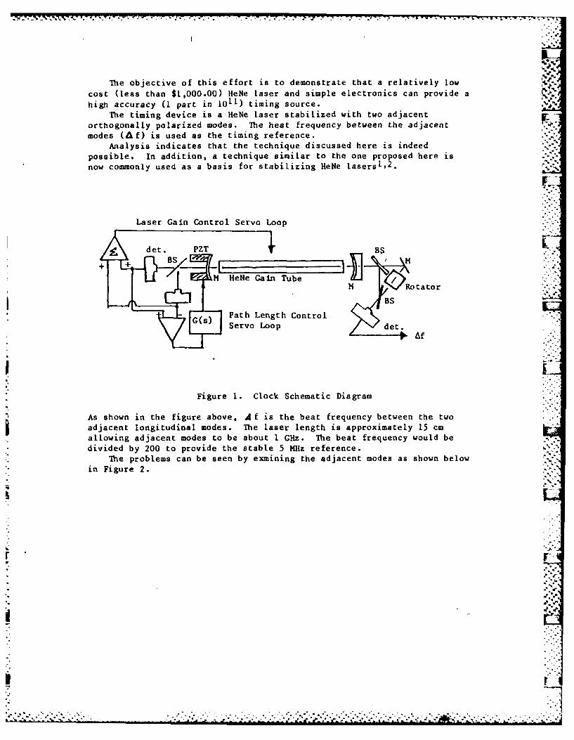
The objective of this effort is to demonstrate that a relatively low
cost (less than $1,000.00) HeNe laser and simple electronics can provide a
high accuracy (1 part in 101 1) timing source.The timing device is a HeNe laser stabilized with two adjacent
orthogonally polarized modes. The heat frequency between the adjacentmodes (A f) is used as the timing reference.
Analysis indicates that the technique discussed here is indeedpossible. In addition, a technique similar to the one proposed here isnow commonly used as a basis for stabilizing HeNe lasersl,2 .
Laser Gain Control Servo Loop
det. PZT BS
M HeNe Gain Tube "'Jf-"
SRtaor
BS
0() Path Length ControlServo Loop / det. Af
Figure 1. Clock Schematic Diagram
As shown in the figure above. A f is the beat frequency between the twoadjacent longitudinal modes. The laser length is approximately 15 cmallowing adjacent modes to be about 1 GHz. The beat frequency would bedivided by 200 to provide the stable 5 MHz reference. 'v
The problems can be seen by exmining the adjacent modes as shown belowin Figure 2.
* -
.."
°.=* ° ~~~~~~~~~~.'.'-o...... ,..,° ..... . . .... °--. . . . .....- ' •...- , .
- .- -- - - - - - -
p
IE
7'
4. k
-- U&"-
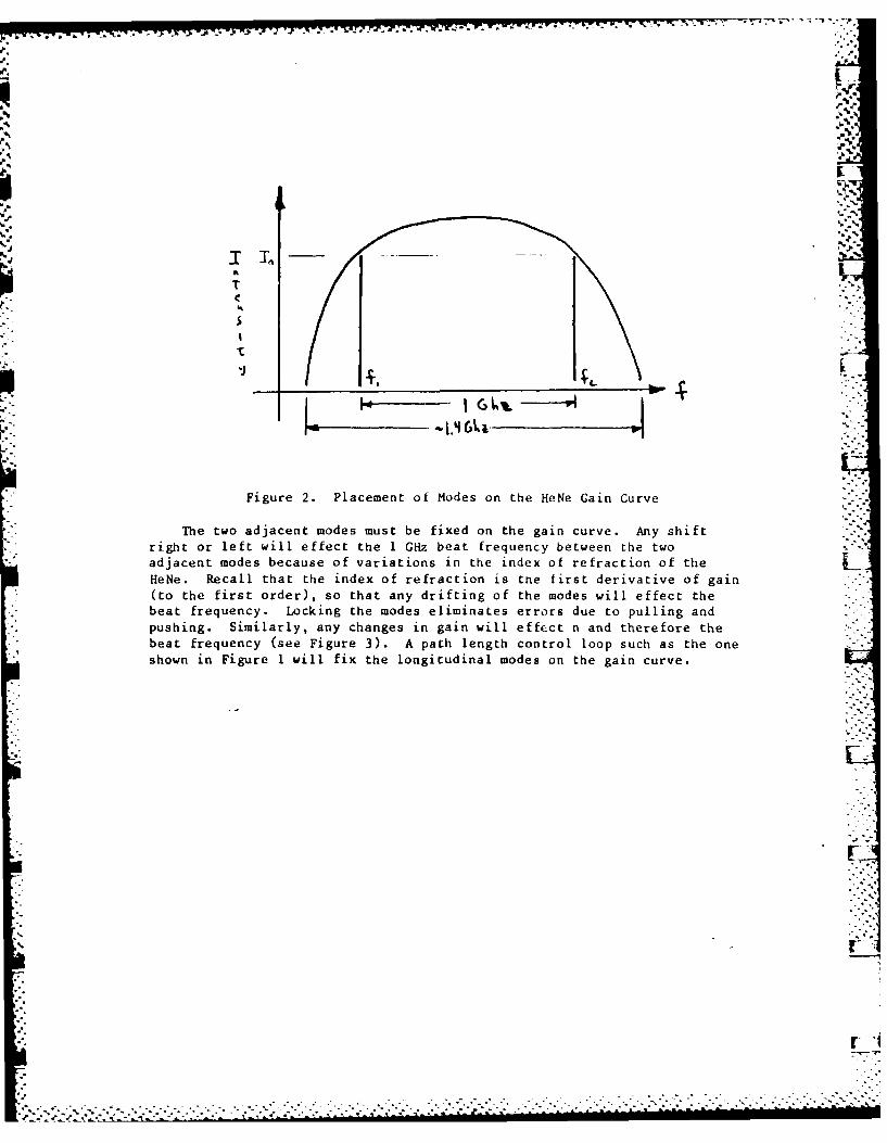
Figure 2. Placement of Modes on the HeNe Gain Curve
The two adjacent modes must be fixed on the gain curve. Any shiftright or left will effect the 1 GHz beat frequency between the twoadjacent modes because of variations in the index of refraction of the LHeNe. Recall that the index of refraction is the first derivative of gain(to the first order), so that any drifting of the modes will effect thebeat frequency. Locking the modes eliminates errors due to pulling andpushing. Similarly, any changes in gain will effect n and therefore thebeat frequency (see Figure 3). A path length control loop such as the oneshown in Figure I will fix the longitudinal modes on the gain curve.
%. .-"

. . . . . . ... . ..... . . . . . . . .
J
Int.
fl f2 -.
n If
Figure 3. Laser Intensity and Index of Refraction versus Frequency
The technique is based upon the premise that the two adjacentlongitudinal modes will be at orthogonal polarizations and thus be
separable. This will be true if care is taken to insure that relativelyequal losses for each mode are incurred in the gain tube, i.e., nobrewster windows, magnets, etc.
The approach is limited by the ability of the servo to fix theadjacent longitudinal modes. The servo is, in turn, limited in bandwidthby the mechanical noise in the laser. A very low noise, and very low
thermal drift material, CERVIT, is used for the laser cavity.
The beat-frequency is derived by rotating the polarization of one ofthe adjacent modes and then sensing the interference of the two modes with
a high frequency, low noise detector. A second method using a single
polarizer at 450 to the two adjacent modes also yields a beat frequencybut at a cost of a low signal to noise figure.
r
-- . .
* REFERENCES
1. R. Balhorn, et.al., "Frequency Stabilization of Internal Mirror
Helium-Neon Lasers," Applied Optics, Vol II, No. 4, Apr 74.
2. Private conversation with Dr. Jan Hall, University of Colorado at
Boulder and NBS, 24 Jan 83.
3. Lt Roger Facklam, "Ultra-Stable Laser Clock," presented at the 36th
Annual Frequency Control Symposium.
*1~*
APPENDIX B'.4'
"-.4"4 I. .44a
I.
4.I- I-'-
*4%-I. .4 -.2'
1~ *1,*
.4
*1
4- 'I.
.4-
~
I'.
.4
.4 * *1* ~
M.4
'III
I,..-

'AV .5 k b
ANl ACTIVE RING LASER GYROSCOPE WITHOUT LOCK-IN:CONCEPT, AND DESIGN
by
Salvatore R. Balsamo, Major, USAF
-.-Frank J. Sailer Research Laboratory (AFSC)United States Air Force AcademyColorado Springs, Colorado 80840
(303) 472-3122/AV 259-3122
%
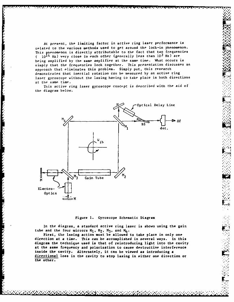
At present, the limiting factor in active ring laser performance is
related to the various methods used to get around the lock-in phenomenon.
This henomenon is directly attributable to the fact that two frequenciesION Hz) very close to each other (generally less than 103 Hz) are
being amplified by the same amplifier at the same time. What occurs is
simply that the frequencies lock together. This presentation discusses an
approach that eliminates this problem. Simply put, this researchdemonstrates that inertial rotation can be measured by an active ring
laser gyroscope without the lasing having to take place in both directions
at the same time.
This active ring laser gyroscope concept is described with the aid of
the diagram below.
rOptical Delay Line
M 'B:."::-
det.
ib
o M3 Gain Tube2
Electro-Optics
Figure 1. Gyroscope Schematic Diagram
In the diagram, a standard active ring laser is shown using the gain
tube and the four mirrors Ml, M2 , M3 , and M4 .
First, the lasing action must be allowed to take place in only onedirection at a time. This can be accomplished in several ways. In thisdiagram the technique used is that of reintroducing light into the cavity
at the same frequency and polarization to cause destructive interferenceinside the cavity. Alternately, it can be viewed as introducing adirectional loss in the cavity to stop lasing in either one direction or
the other.
4.
- L
.". 4. .* 4 *,' J*. .-.. ** ... . . . . .

The electro-optic is used to rotate the polarization of the laser beamby 900 on reintroduction into the laser. This is accomplished byapplying a 1/4 wave voltage to the electro-optic. The polarization thenchanges from S (linear) to right hand circular. The reflection off themirror then changes it to left hand circular which becomes p (linear)-onpassing through the electro-optic for the second time. Thus, with theelectro-optic on the polarization is orthogonal to the polarization of thelaser and therefore has no effect on the circulating beam (see Figure 2).
Laser
External roMirror E/O (on)
r &r
Figure 2. Polarization Changes for the System with the E/O "On"
With the E/O off there is no rotation and so the returning beam interferesand causes the lasing action to stop. In the ring laser there are twoexternal E/O's. One for each direction which are alternately switched onand off.
If we look at the ring laser output at mirror M1 in Figure 1, itwould alternate as shown in Figure 3.
TimeFigure~~ ~ ~ ~ ~ 3 . OuptBamitnite tH
77....Ioc14 ...
Figure 3. Output Beam Intensities at M
-. -C
-. : * *::::
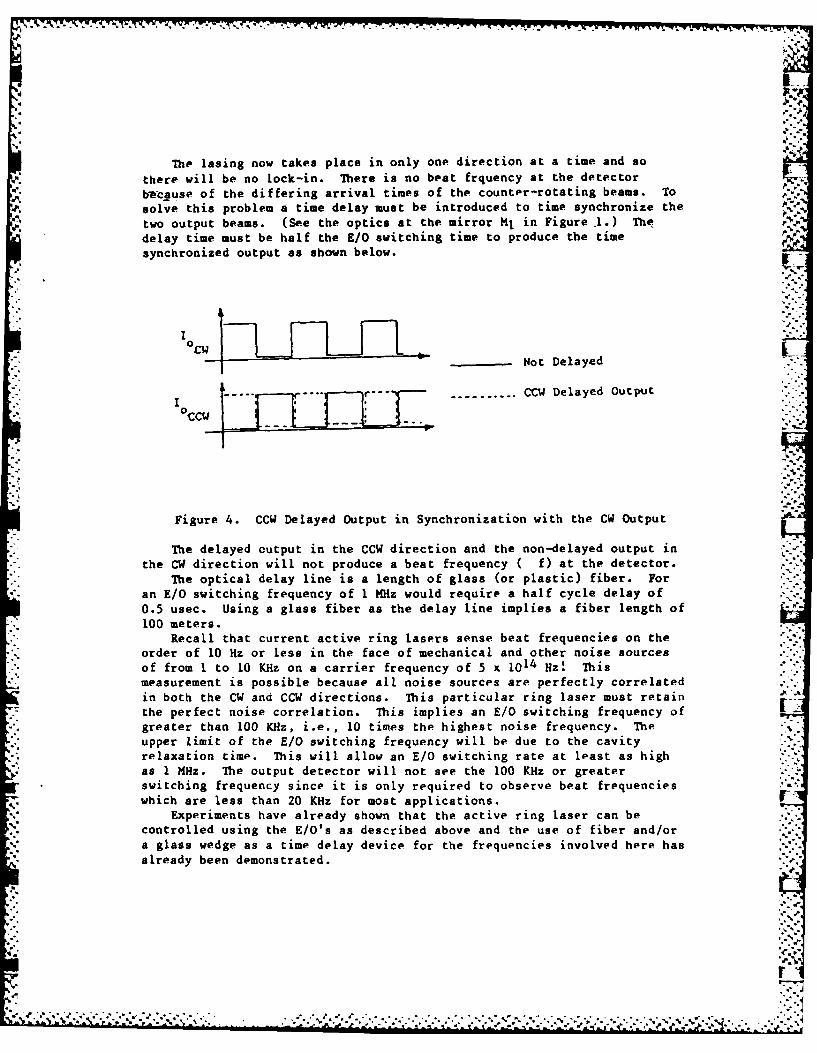
The lasing now takes place in only one direction at a time and so
there will be no lock-in. There is no beat frquency at the detector
beause of the differing arrival times of the counter-rotating beams. To
solve this problem a time delay must be introduced to time synchronize the
two output beams. (See the optics at the mirror Ml in Figure.l.) The!
delay time must be half the K/O switching time to produce the timesynchronized output as shown below.
°-{ - Not Delayed "
-------------------- CCW Delayed Output°CC '.'
Figure 4. CCW Delayed Output in Synchronization with the CW Output
The delayed output in the CCW direction and the non-delayed output inthe CW direction will not produce a beat frequency ( f) at the detector.
The optical delay line is a length of glass (or plastic) fiber. Foran E/O switching frequency of I MHz would require a half cycle delay of
0.5 usec. Using a glass fiber as the delay line implies a fiber length of100 meters.
Recall that current active ring lasers sense beat frequencies on theorder of 10 Hz or less in the face of mechanical and other noise sourcesof from I to 10 KHz on a carrier frequency of 5 x 10¹⁴ Hz! Thismeasurement is possible because all noise sources are perfectly correlatedin both the CW and CCW directions. This particular ring laser must retain
the perfect noise correlation. This implies an E/O switching frequency of rgreater than 100 KHz, i.e., 10 times the highest noise frequency. Theupper limit of the E/O switching frequency will be due to the cavityrelaxation time. This will allow an E/O switching rate at least as highas 1 MHz. The output detector will not see the 100 KHz or greater
switching frequency since it is only required to observe beat frequencies
which are less than 20 KHz for most applications.Experiments have already shown that the active ring laser can be
controlled using the E/0's as described above and the use of fiber and/ora glass wedge as a time delay device for the frequencies involved here hasalready been demonstrated.
.-
rl
~7'-~'~~--~-~--- ~* 2JP.b ~ .& -.
II
A
4~.
~( sq
Is'
~
~Ot
trtmou4 - * -
r.
-a
*1/ a-5%~
"I
'p4.5".
SI5
'p
~ .y .-.


![v (} /v À v }v (} lv]vP - CFKR€¦ · handlinger om faggrænser, overvejesamt lser om samt hvem der skal varetage de arbejds-opgaver, der følgermed instruksen. Medarbejdernes egne](https://static.fdocuments.net/doc/165x107/5f53cc698be9d917be0101aa/v-v-v-v-lvvp-cfkr-handlinger-om-faggrnser-overvejesamt-lser-om.jpg)


