
DVI Fiberlynx - Lantronix2.2 Connecting Fiber Optic Cable 1. Install the Transmitter and Receiver...
18
DVI Fiberlynx PN 15.00.033 Product Manual November 2001 Revision B
Transcript of DVI Fiberlynx - Lantronix2.2 Connecting Fiber Optic Cable 1. Install the Transmitter and Receiver...
DVI Fiberlynx
PN 15.00.033
Product Manual
November 2001
Revision B
Lightwave Communications DVI Fiberlynx
www.lightwavecom.com November 2001 2
Lightwave Communications, Inc. 100 Washington Street Milford, CT 06460 USA
(800) 871-9838 • (203) 878-9838 • Fax: (203) 874-0157 Email: [email protected] • Internet: www.lightwavecom.com
LCI Asia/Pacific postal address: P.O. Box 19 GlenIris VIC 3146 Australia
delivery address: 16 Network Drive Port Melbourne VIC 3207 Australia +61 3 9646 1144 • Fax: +61 3 9645 3377
Email: [email protected] • Internet: www.lightwavecom.com.au
LCI Europe Zaubzerstraβe 11 Munich D-81677 Germany
49-89-306-3810 • Fax: 49-89-306-3812 Email: [email protected] • Internet: www.lightwave.de
VDI Fiberlynx User Manual LCI Part Number 15.00.033
Edition of November 14, 2001 - Revision B Copyright 2000-2001 Lightwave Communications, Inc.
100 Washington Street, Milford, CT, 06460, USA All rights reserved. No part of this copyrighted material may be reproduced in any form or by any means without prior written permission from Lightwave Communications, Inc.
Lightwave Communications is a Lantronix Company.

Lightwave Communications DVI Fiberlynx
www.lightwavecom.com November 2001 3
Table of Contents 1.0 System Overview....................................................................................... 4 2.0 Installation ................................................................................................. 5
2.1 Site Preparation ..................................................................................... 6 2.2 Connecting Fiber Optic Cable................................................................ 6 2.3 DVI Cable Kits........................................................................................ 8 2.4 Connecting the CPU to the Transmitter ................................................. 8 2.4 Connecting the User Peripherals ......................................................... 10
3.0 Operation................................................................................................. 12 3.1 Video Record ....................................................................................... 12 3.2 Video Resolution.................................................................................. 12 3.3 Front Panel LEDs................................................................................. 12
Appendix A Serial Port Pinouts .................................................................... 15 Appendix B Specifications ............................................................................ 16
B.1 Physical ............................................................................................... 16 B.2 Environmental ...................................................................................... 16 B.3 Electrical .............................................................................................. 16 B.4 Optical.................................................................................................. 16 B.5 Interface............................................................................................... 17 B.6 Compliance and Certification ............................................................... 18
Lightwave Communications DVI Fiberlynx
www.lightwavecom.com November 2001 4
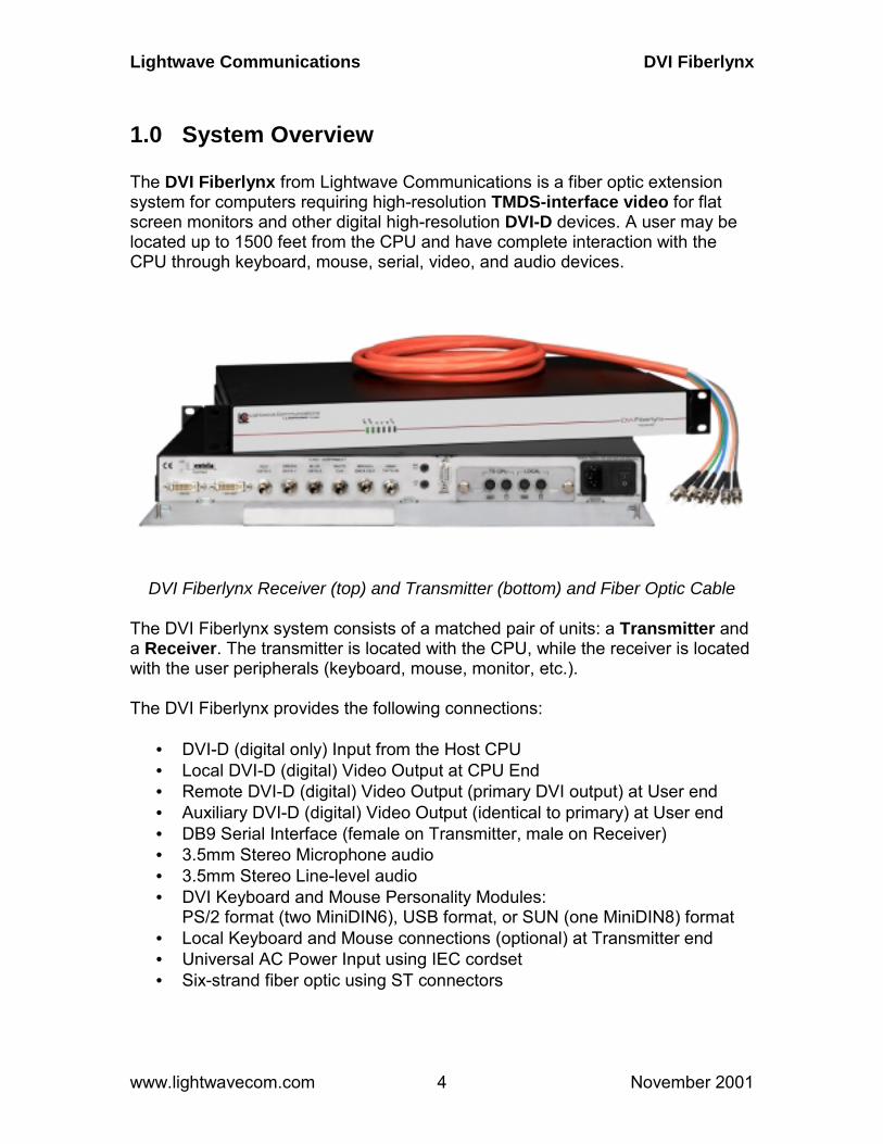
1.0 System Overview The DVI Fiberlynx from Lightwave Communications is a fiber optic extension system for computers requiring high-resolution TMDS-interface video for flat screen monitors and other digital high-resolution DVI-D devices. A user may be located up to 1500 feet from the CPU and have complete interaction with the CPU through keyboard, mouse, serial, video, and audio devices.
DVI Fiberlynx Receiver (top) and Transmitter (bottom) and Fiber Optic Cable The DVI Fiberlynx system consists of a matched pair of units: a Transmitter and a Receiver. The transmitter is located with the CPU, while the receiver is located with the user peripherals (keyboard, mouse, monitor, etc.). The DVI Fiberlynx provides the following connections:
• DVI-D (digital only) Input from the Host CPU • Local DVI-D (digital) Video Output at CPU End • Remote DVI-D (digital) Video Output (primary DVI output) at User end • Auxiliary DVI-D (digital) Video Output (identical to primary) at User end • DB9 Serial Interface (female on Transmitter, male on Receiver) • 3.5mm Stereo Microphone audio • 3.5mm Stereo Line-level audio • DVI Keyboard and Mouse Personality Modules:
PS/2 format (two MiniDIN6), USB format, or SUN (one MiniDIN8) format • Local Keyboard and Mouse connections (optional) at Transmitter end • Universal AC Power Input using IEC cordset • Six-strand fiber optic using ST connectors
Lightwave Communications DVI Fiberlynx
www.lightwavecom.com November 2001 5
The DVI Fiberlynx system provides keyboard emulation and carries the keyboard and mouse signals through the Transmitter to the Receiver end. The Personality Modules must be used as a matched set (e.g., PS/2 on both ends, or USB on both ends, etc.). No 'breaks' are sent to the CPU (which might cause the CPU to reset), even if the DVI Fiberlynx units lose power, as long as the keyboard cable remains connected to the Transmitter. The DVI video record (DDC) is maintained in the event the DVI Fiberlynx is powered off, as long as the DVI input cable remains connected to the Transmitter. The CPU, or its video output, does not need to be restarted in this case.
2.0 Installation Installation of the DVI Fiberlynx is simple and requires only simple hand tools. Each Fiberlynx transmitter or receiver can be mounted in a standard 19-inch rack, or may be placed on a bench or table. The DVI Fiberlynx has been classified a CLASS 1 LASER Product in accordance with standards IEC 60825-1 and IEC 60825-2. Always operate the product in accordance with these instructions.
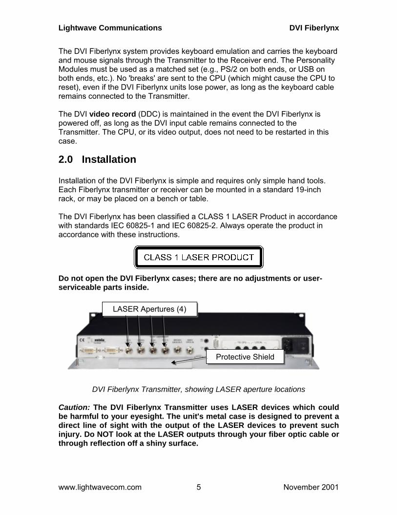
Do not open the DVI Fiberlynx cases; there are no adjustments or user-serviceable parts inside.
DVI Fiberlynx Transmitter, showing LASER aperture locations Caution: The DVI Fiberlynx Transmitter uses LASER devices which could be harmful to your eyesight. The unit's metal case is designed to prevent a direct line of sight with the output of the LASER devices to prevent such injury. Do NOT look at the LASER outputs through your fiber optic cable or through reflection off a shiny surface.
LASER Apertures (4)
Protective Shield

Lightwave Communications DVI Fiberlynx
www.lightwavecom.com November 2001 6
2.1 Site Preparation 1. Shutdown the CPU and disconnect the user peripherals (keyboard,
mouse, monitor, etc.). 2. Move the CPU and the user devices to their respective operating
locations. Standard cable kits provide 6 feet of copper cable length between the CPU and the Transmitter unit; other lengths are available.
3. Run a 6-strand fiber optic cable with ST connectors between the CPU
location and user station. Fiber optic cable is available in custom and standard lengths from Lightwave Communications.
Caution: Do NOT look at the LASER outputs through your fiber optic cable or through reflection off a shiny surface. The LASER light can be harmful to your vision. 4. Provide AC power connections for the DVI Fiberlynx units at each
location, as well as power for the CPU and any powered user peripherals (such as a monitor and speakers). The DVI Fiberlynx uses a universal power supply.
2.2 Connecting Fiber Optic Cable 1. Install the Transmitter and Receiver units close to their final locations. If
not already in place, run the fiber optic cable to these locations with enough slack to prevent strain from damaging the cable.
DVI Fiberlynx Transmitter, Fiber Optic ST connectors and Audio Jacks 2. Attach the individual fiber strands to the ST connectors on the back of
each unit, using a color-to-color match. Each strand on the Transmitter end should be attached to the same connector as on the Receiver end
Protective Metal Light Shield
Lightwave Communications DVI Fiberlynx
www.lightwavecom.com November 2001 7
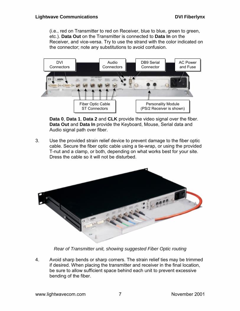
(i.e., red on Transmitter to red on Receiver, blue to blue, green to green, etc.). Data Out on the Transmitter is connected to Data In on the Receiver, and vice-versa. Try to use the strand with the color indicated on the connector; note any substitutions to avoid confusion.
Data 0, Data 1, Data 2 and CLK provide the video signal over the fiber. Data Out and Data In provide the Keyboard, Mouse, Serial data and Audio signal path over fiber.
3. Use the provided strain relief device to prevent damage to the fiber optic
cable. Secure the fiber optic cable using a tie-wrap, or using the provided T-nut and a clamp, or both, depending on what works best for your site. Dress the cable so it will not be disturbed.
Rear of Transmitter unit, showing suggested Fiber Optic routing 4. Avoid sharp bends or sharp corners. The strain relief ties may be trimmed
if desired. When placing the transmitter and receiver in the final location, be sure to allow sufficient space behind each unit to prevent excessive bending of the fiber.
Fiber Optic Cable ST Connectors
Personality Module (PS/2 Receiver is shown)
DVI Connectors
Audio Connectors
DB9 Serial Connector
AC Power and Fuse
Lightwave Communications DVI Fiberlynx
www.lightwavecom.com November 2001 8
2.3 DVI Cable Kits A six-foot-long DVI cable kit is included with the DVI Fiberlynx to connect the DVI Transmitter to your CPU. Use this kit at the CPU end. The cable kits include: one male-to-male TMDS (DVI-D connector) video cable, keyboard and mouse cables (varies per kit), one male-to-female DB9 serial cable, and two 3.5 mm audio cables. Eight rubber feet are also included to use the DVI Fiberlynx on a desktop, and 8 tie-wraps.
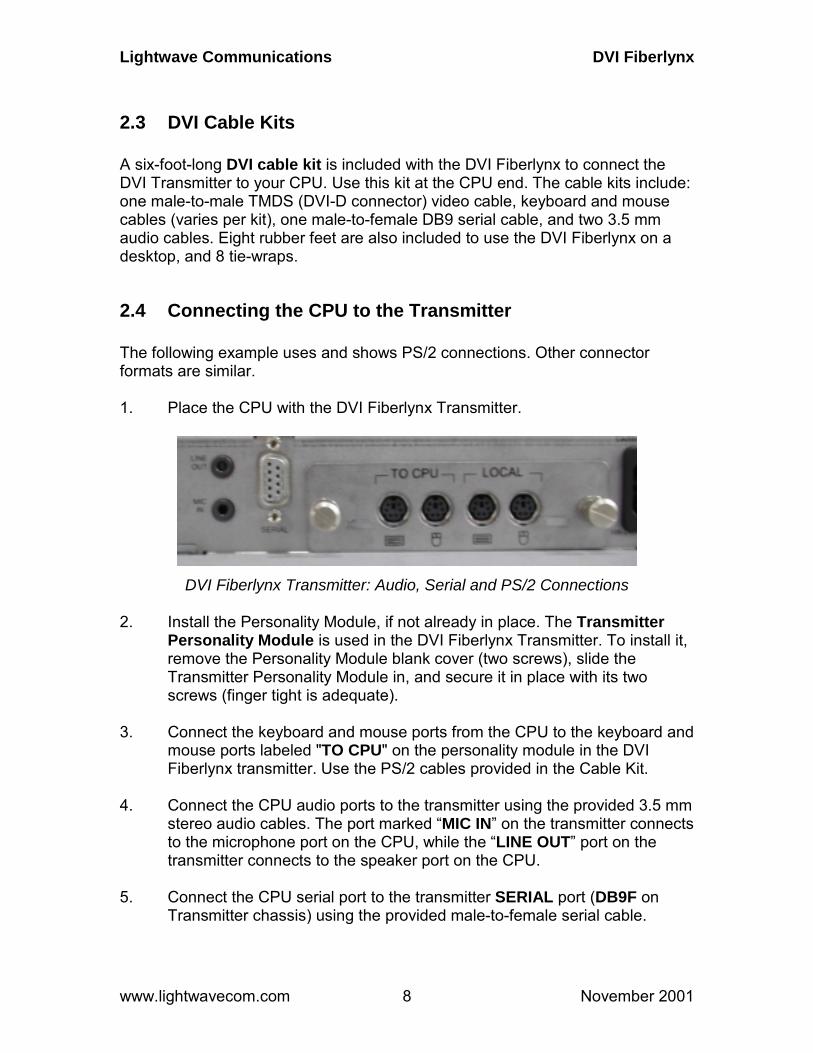
2.4 Connecting the CPU to the Transmitter The following example uses and shows PS/2 connections. Other connector formats are similar. 1. Place the CPU with the DVI Fiberlynx Transmitter.
DVI Fiberlynx Transmitter: Audio, Serial and PS/2 Connections 2. Install the Personality Module, if not already in place. The Transmitter
Personality Module is used in the DVI Fiberlynx Transmitter. To install it, remove the Personality Module blank cover (two screws), slide the Transmitter Personality Module in, and secure it in place with its two screws (finger tight is adequate).
3. Connect the keyboard and mouse ports from the CPU to the keyboard and
mouse ports labeled "TO CPU" on the personality module in the DVI Fiberlynx transmitter. Use the PS/2 cables provided in the Cable Kit.
4. Connect the CPU audio ports to the transmitter using the provided 3.5 mm
stereo audio cables. The port marked “MIC IN” on the transmitter connects to the microphone port on the CPU, while the “LINE OUT” port on the transmitter connects to the speaker port on the CPU.
5. Connect the CPU serial port to the transmitter SERIAL port (DB9F on
Transmitter chassis) using the provided male-to-female serial cable.
Lightwave Communications DVI Fiberlynx
www.lightwavecom.com November 2001 9
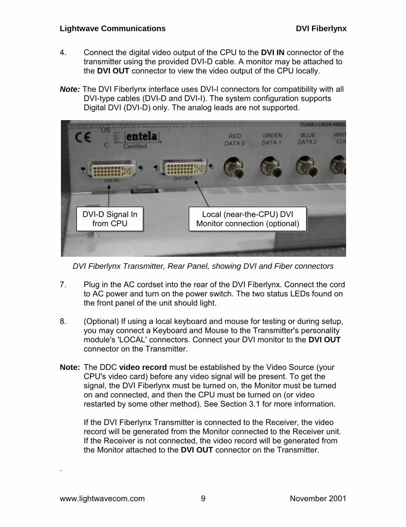
4. Connect the digital video output of the CPU to the DVI IN connector of the transmitter using the provided DVI-D cable. A monitor may be attached to the DVI OUT connector to view the video output of the CPU locally.
Note: The DVI Fiberlynx interface uses DVI-I connectors for compatibility with all
DVI-type cables (DVI-D and DVI-I). The system configuration supports Digital DVI (DVI-D) only. The analog leads are not supported.
DVI Fiberlynx Transmitter, Rear Panel, showing DVI and Fiber connectors 7. Plug in the AC cordset into the rear of the DVI Fiberlynx. Connect the cord
to AC power and turn on the power switch. The two status LEDs found on the front panel of the unit should light.
8. (Optional) If using a local keyboard and mouse for testing or during setup,
you may connect a Keyboard and Mouse to the Transmitter's personality module's 'LOCAL' connectors. Connect your DVI monitor to the DVI OUT connector on the Transmitter.
Note: The DDC video record must be established by the Video Source (your
CPU's video card) before any video signal will be present. To get the signal, the DVI Fiberlynx must be turned on, the Monitor must be turned on and connected, and then the CPU must be turned on (or video restarted by some other method). See Section 3.1 for more information.
If the DVI Fiberlynx Transmitter is connected to the Receiver, the video
record will be generated from the Monitor connected to the Receiver unit. If the Receiver is not connected, the video record will be generated from the Monitor attached to the DVI OUT connector on the Transmitter.
.
DVI-D Signal In from CPU
Local (near-the-CPU) DVI Monitor connection (optional)
Lightwave Communications DVI Fiberlynx
www.lightwavecom.com November 2001 10
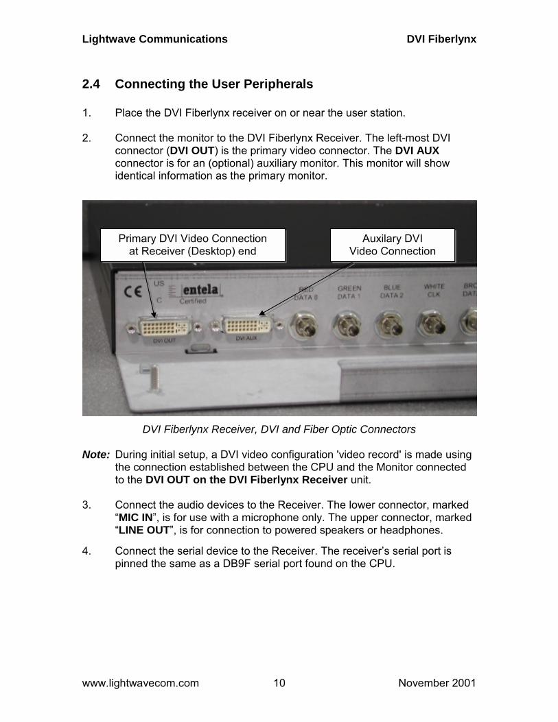
2.4 Connecting the User Peripherals 1. Place the DVI Fiberlynx receiver on or near the user station. 2. Connect the monitor to the DVI Fiberlynx Receiver. The left-most DVI
connector (DVI OUT) is the primary video connector. The DVI AUX connector is for an (optional) auxiliary monitor. This monitor will show identical information as the primary monitor.
DVI Fiberlynx Receiver, DVI and Fiber Optic Connectors Note: During initial setup, a DVI video configuration 'video record' is made using
the connection established between the CPU and the Monitor connected to the DVI OUT on the DVI Fiberlynx Receiver unit.
3. Connect the audio devices to the Receiver. The lower connector, marked
“MIC IN”, is for use with a microphone only. The upper connector, marked “LINE OUT”, is for connection to powered speakers or headphones.
4. Connect the serial device to the Receiver. The receiver’s serial port is
pinned the same as a DB9F serial port found on the CPU.
Primary DVI Video Connection at Receiver (Desktop) end
Auxilary DVI Video Connection

Lightwave Communications DVI Fiberlynx
www.lightwavecom.com November 2001 11
DVI Fiberlynx Receiver, Audio, Serial and PS/2 Connections
5. Connect the Receiver to AC power and turn on the switch. The status
LEDs found on the front of the unit should light. The Monitor and the CPU may be powered up at this time.
2.5 Power Up the Equipment The video signal from your DVI video source requires that the DVI monitor is connected and turned on before the signal will start. If the signal is lost (cable is unplugged, etc.) the signal will be discontinued and will not recover; the video source must be restarted. This often means that your CPU must be restarted. Power Up your equipment in this order (after all wiring connections are done):
1. Power Up your Monitor 2. Power Up the DVI Fiberlynx Receiver and Transmitter units 3. Power Up your CPU.
During power-up of your CPU, the video card generates a video record depending on the DVI monitor that it senses is connected to its output. See section 3.1 for more information relating to the video record.
Lightwave Communications DVI Fiberlynx
www.lightwavecom.com November 2001 12
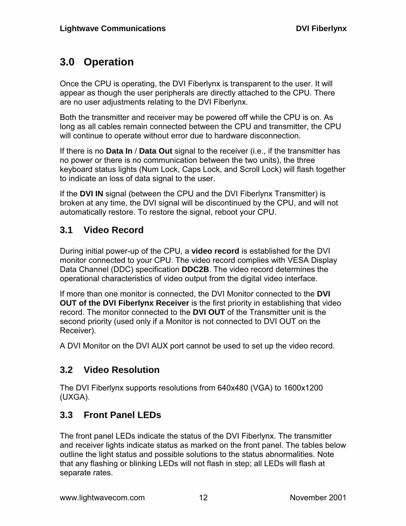
3.0 Operation Once the CPU is operating, the DVI Fiberlynx is transparent to the user. It will appear as though the user peripherals are directly attached to the CPU. There are no user adjustments relating to the DVI Fiberlynx. Both the transmitter and receiver may be powered off while the CPU is on. As long as all cables remain connected between the CPU and transmitter, the CPU will continue to operate without error due to hardware disconnection. If there is no Data In / Data Out signal to the receiver (i.e., if the transmitter has no power or there is no communication between the two units), the three keyboard status lights (Num Lock, Caps Lock, and Scroll Lock) will flash together to indicate an loss of data signal to the user. If the DVI IN signal (between the CPU and the DVI Fiberlynx Transmitter) is broken at any time, the DVI signal will be discontinued by the CPU, and will not automatically restore. To restore the signal, reboot your CPU.
3.1 Video Record During initial power-up of the CPU, a video record is established for the DVI monitor connected to your CPU. The video record complies with VESA Display Data Channel (DDC) specification DDC2B. The video record determines the operational characteristics of video output from the digital video interface. If more than one monitor is connected, the DVI Monitor connected to the DVI OUT of the DVI Fiberlynx Receiver is the first priority in establishing that video record. The monitor connected to the DVI OUT of the Transmitter unit is the second priority (used only if a Monitor is not connected to DVI OUT on the Receiver). A DVI Monitor on the DVI AUX port cannot be used to set up the video record.
3.2 Video Resolution The DVI Fiberlynx supports resolutions from 640x480 (VGA) to 1600x1200 (UXGA).
3.3 Front Panel LEDs The front panel LEDs indicate the status of the DVI Fiberlynx. The transmitter and receiver lights indicate status as marked on the front panel. The tables below outline the light status and possible solutions to the status abnormalities. Note that any flashing or blinking LEDs will not flash in step; all LEDs will flash at separate rates.

Lightwave Communications DVI Fiberlynx
www.lightwavecom.com November 2001 13
The DVI Fiberlynx Receiver has six front panel LEDs which show Status of the Receiver plus the Status of the Red, Green, Blue and Sync. Clock. Normal 'good' indication is the two left-most LEDs flashing green, the other LEDs off. The LEDs on the DVI Receiver, from left to right are: Unit Transmit, Unit Receive, Video Blue, Video Green, Video Red, and Video Clock. Receiver Unit
label appearance status action TxD blinking green normal solid green unit not transmitting
data • cycle power
RxD blinking green normal solid red or
orange not receiving data • check fiber connections
• cycle power on both units B- off normal solid red /
solid green adjusting coarse gain / adjusting fine gain
normal at start if constantly adjusting:
• check fiber connection marked “BLUE”
• check fiber distance between stations
• check video source G- off normal solid red /
solid green adjusting coarse gain / adjusting fine gain
normal at start if constantly adjusting:
• check fiber connection marked “GREEN”
• check fiber distance between stations
• check video source R- off normal solid red /
solid green adjusting coarse gain / adjusting fine gain
normal at start if constantly adjusting:
• check fiber connection marked “RED”
• check fiber distance between stations
• check video source CLK off normal solid red or
orange not receiving sync data
• check fiber connections • cycle power
The DVI Fiberlynx Transmitter has two front panel LEDs which show Transmitter Status. Normal 'good' indication for both LEDs is a green flashing condition.

Lightwave Communications DVI Fiberlynx
www.lightwavecom.com November 2001 14
The LEDs on the Transmitter, from left to right, are 'Unit Receive and 'Unit Transmit'. Transmitter Unit
label appearance status action RxD blinking green normal solid green unit not receiving
data • check fiber connections • cycle power
TxD blinking green normal solid red or
orange not transmitting data • check fiber connections
• cycle power on both units
Lightwave Communications DVI Fiberlynx
www.lightwavecom.com November 2001 15
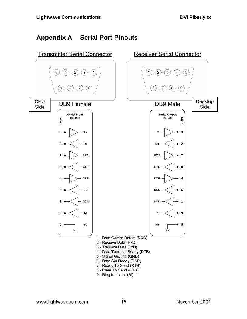
Appendix A Serial Port Pinouts
DB9 Female
4
7
23
9 8 6
15
DB9 Male
2
8
43
6 7 9
51
Transmitter Serial Connector Receiver Serial Connector
1 - Data Carrier Detect (DCD)2 - Receive Data (RxD)3 - Transmit Data (TxD)4 - Data Terminal Ready (DTR)5 - Signal Ground (GND)6 - Data Set Ready (DSR)7 - Ready To Send (RTS)8 - Clear To Send (CTS)9 - Ring Indicator (RI)
1
4
6
8
7
2
3
5
Tx
Rx
RTS
CTS
DTR
DSR
DCD
SG
Serial OutputRS-232
9RI
DB
9M
1
4
6
8
7
2
3
5
Tx
Rx
RTS
CTS
DTR
DSR
DCD
SG
Serial InputRS-232
RI9
DB
9F
CPU Side
Desktop Side
Lightwave Communications DVI Fiberlynx
www.lightwavecom.com November 2001 16
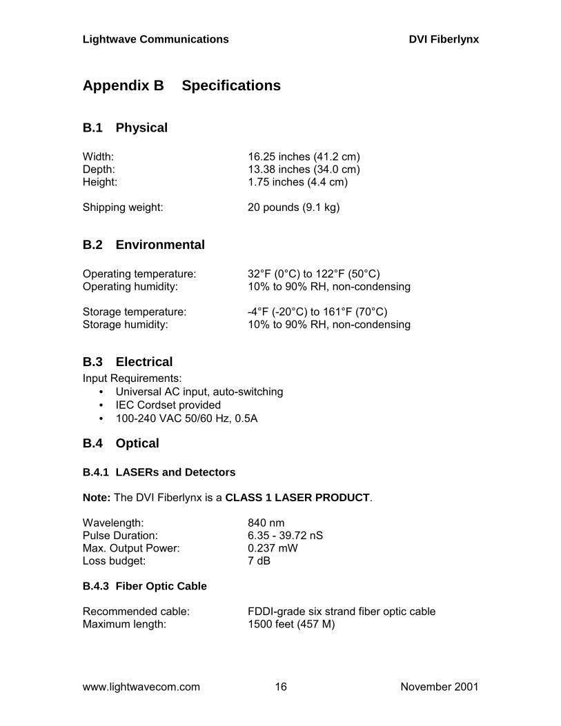
Appendix B Specifications
B.1 Physical Width: 16.25 inches (41.2 cm) Depth: 13.38 inches (34.0 cm) Height: 1.75 inches (4.4 cm) Shipping weight: 20 pounds (9.1 kg)
B.2 Environmental Operating temperature: 32°F (0°C) to 122°F (50°C) Operating humidity: 10% to 90% RH, non-condensing Storage temperature: -4°F (-20°C) to 161°F (70°C) Storage humidity: 10% to 90% RH, non-condensing
B.3 Electrical Input Requirements:
• Universal AC input, auto-switching • IEC Cordset provided • 100-240 VAC 50/60 Hz, 0.5A
B.4 Optical B.4.1 LASERs and Detectors Note: The DVI Fiberlynx is a CLASS 1 LASER PRODUCT. Wavelength: 840 nm Pulse Duration: 6.35 - 39.72 nS Max. Output Power: 0.237 mW Loss budget: 7 dB B.4.3 Fiber Optic Cable Recommended cable: FDDI-grade six strand fiber optic cable Maximum length: 1500 feet (457 M)
Lightwave Communications DVI Fiberlynx
www.lightwavecom.com November 2001 17
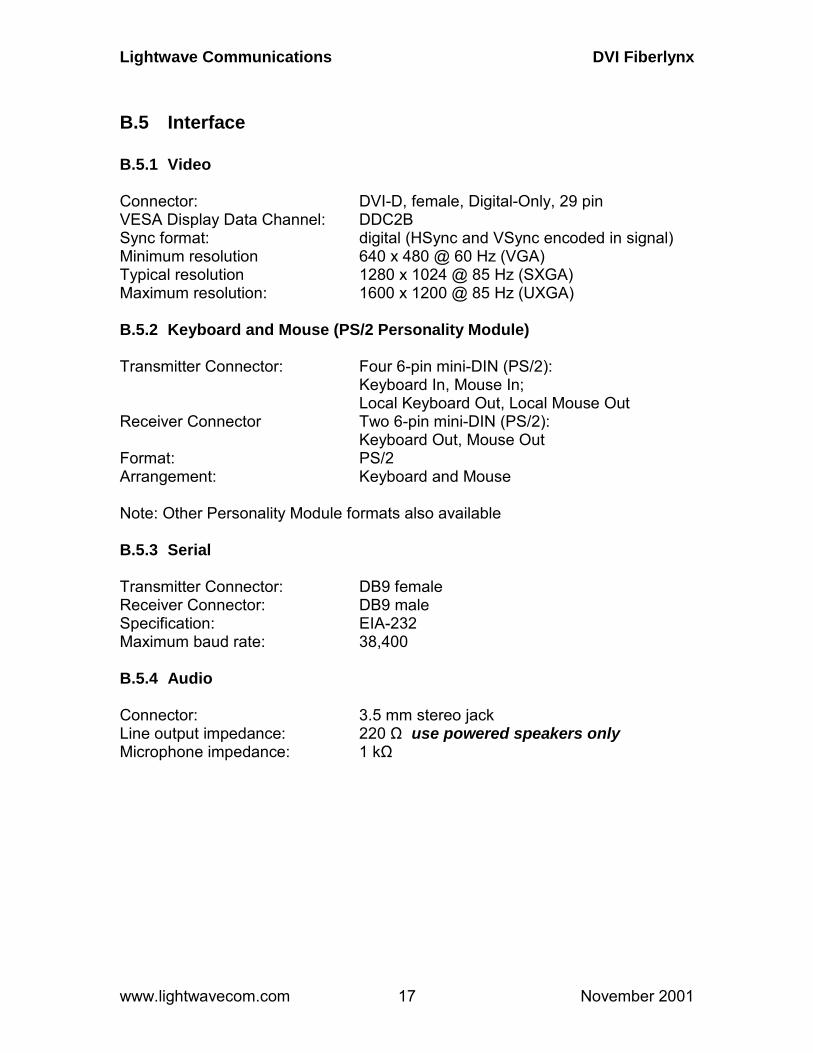
B.5 Interface B.5.1 Video Connector: DVI-D, female, Digital-Only, 29 pin VESA Display Data Channel: DDC2B Sync format: digital (HSync and VSync encoded in signal) Minimum resolution 640 x 480 @ 60 Hz (VGA) Typical resolution 1280 x 1024 @ 85 Hz (SXGA) Maximum resolution: 1600 x 1200 @ 85 Hz (UXGA) B.5.2 Keyboard and Mouse (PS/2 Personality Module) Transmitter Connector: Four 6-pin mini-DIN (PS/2):
Keyboard In, Mouse In; Local Keyboard Out, Local Mouse Out
Receiver Connector Two 6-pin mini-DIN (PS/2): Keyboard Out, Mouse Out
Format: PS/2 Arrangement: Keyboard and Mouse Note: Other Personality Module formats also available B.5.3 Serial Transmitter Connector: DB9 female Receiver Connector: DB9 male Specification: EIA-232 Maximum baud rate: 38,400 B.5.4 Audio Connector: 3.5 mm stereo jack Line output impedance: 220 Ω use powered speakers only Microphone impedance: 1 kΩ
Lightwave Communications DVI Fiberlynx
www.lightwavecom.com November 2001 18
B.6 Compliance and Certification CLASS 1 LASER PRODUCT The DVI Fiberlynx has been classified a CLASS 1 LASER Product in accordance with standards IEC 60825-1 and IEC 60825-2. Always operate the product in accordance with the instructions contained in Section 2 of the manual.
Entela Electrical Safety Certification (equivalent to UL 1950 and CSA 950)
Entela is a USA OSHA Nationally Recognized Testing Laboratory (NRTL), an accredited Certification Organization by the Standards Council of Canada (SCC), and an IECEE – CB Scheme National Certification Body (NCB) & Certification Body Testing Laboratory (CBTL).
CE certification Conforms to FCC part 15, Class A Note: This equipment has been tested and found to comply with the limits for a Class A digital device, pursuant to Part 15 of the FCC Rules. The limits are designed to provide a reasonable protection against harmful interference when the equipment is operated in a commercial environment. The equipment generates, uses and can radiate energy and, if not installed and used in accordance with the instruction manual, may cause harmful interference to radio communications. Operation of this equipment in a residential area is likely to cause harmful interference in which case the user will be required to correct the interference at their own expense.


