Dvb s2-vcm
3
224 225 TELE-satellite International — The World‘s Largest Digital TV Trade Magazine — 04-05/2012 — www.TELE-satellite.com www.TELE-satellite.com — 04-05/2012 — TELE-satellite International — The World‘s Largest Digital TV Trade Magazine • allows more than one stream for each transponder • dynamic change of FEC coding rates • different content can bes assigend to different transmission modes • compatible tuner needs function to determine coding rates • - VCM signals only receivable with compatible tuners VCM Signal Reception FEATURE VCM Tuner
-
Upload
tele-audiovision-eng -
Category
Entertainment & Humor
-
view
153 -
download
9
Transcript of Dvb s2-vcm
224 225TELE-satellite International — The World‘s Largest Digital TV Trade Magazine — 04-05/2012 — www.TELE-satellite.com www.TELE-satellite.com — 04-05/2012 — TELE-satellite International — The World‘s Largest Digital TV Trade Magazine
•allowsmorethanonestreamforeachtransponder•dynamicchangeofFECcodingrates•differentcontentcanbesassigendtodifferenttransmissionmodes•compatibletunerneedsfunctiontodeterminecodingrates•-VCMsignalsonlyreceivablewithcompatibletuners
VCM Signal Reception
FEATURE VCM Tuner
■
226 TELE-satellite International — The World‘s Largest Digital TV Trade Magazine — 04-05/2012 — www.TELE-satellite.com
How a tuner for VCM operates - an indepth look into today‘s most advanced transmission technologyJacek Pawlowski
FEATURE
The DVB-S2 standard, published in 2003, is a significant step forward from DVB-S. Its most obvious advantage is a better spectral efficiency as compared to DVB-S. Within the same transmis-sion channel you can send up to 30% more data. Its performance is very close to the Shannon limit – only 1 dB below, so in fact one should not expect any further improvement in data rate achievable within a given transmission channel. However, there is another as-pect of digital data transmissions – for-ward error correction or FEC.
Although the actual implementa-tion is very complex, the essence of FEC is simple. Having digital informa-tion (e.g. video, audio, Internet data) the encoder divides it into packets or frames and adds extra bits calculated in a special way from the useful digital content. Those extra bits are transmit-ted together with the “useful” bits. If some of the bits, either the useful ones or the additional ones, are distorted (1 becomes 0 or vice versa), the recep-tion system which “knows” what the relationship between the normal and additional bits should be, can do so-phisticated calculations and restore the original form of useful bits.
DVB-S2 introduced new algorithms for FEC: BCH and LDPC. BCH (Bose-Chaudhuri-Hocquenghem) replaced Reed Solomon coding used in DVB-S. LDPC (Low Density Parity Check) re-placed Viterbi inner coding. LDPC, a method invented in 1960’s by Gallag-
er, became feasible only recently after advances in IC technology had been made. LDPC uses the following inner code rates: 1/4, 1/3, 2/5, 1/2, 3/5, 2/3, 3/4, 4/5, 5/6, 8/9, 9/10.
These numbers are quite familiar for satellite fans. The meaning of them is simple – this is the ratio of the useful bits to the sum of useful bits and ad-ditional bits added for error correction. As you can deduce, the most effective inner coding rate is 9/10 but at the same time is most vulnerable to inter-ference. Inner coding rate 1/4 is very robust as for one useful bit there are three additional bits for error correc-tion but, of course, the efficiency of the transmission is very poor.
In the old days of DVB-S we had to use one fixed inner coding rate for one transponder. One transponder trans-mitted only one transport stream. Every TV channel or the other service included in the transport stream was transmitted with the same spectral effi-ciency and interference robustness be-cause the same inner coding was used for the whole transponder.
DVB-S2 offers more flexibility in this aspect. Except for CCM (Constant Cod-ing and Modulation), we have two more options: VCM (Variable Coding and Modulation) and ACM (Adaptive Coding and Modulation). VCM and ACM are the methods to send more than one trans-port stream within the same carrier (same transponder). In VCM, we can set different coding rates for different
transport streams and in ACM we can even dynamically change the coding rates depending on the feedback infor-mation from the reception system.
While ACM is very useful in point to point transmissions where there is only one recipient of the information, VCM can be quite useful for satellite TV transmission for a large audience. The content provider may choose to trans-mit the very basic package of the SD TV channels with a strong error cor-rection – thus making it receivable also at the edges of the satellite footprint, while the premium HD channels may be transmitted with weaker correction, so that their reception is guaranteed only in the central part of the footprint where most of the subscribers live. To achieve stronger or weaker error cor-rection, the provider chooses both modulation type (e.g.: QPSK or 8PSK) and inner coding rate.
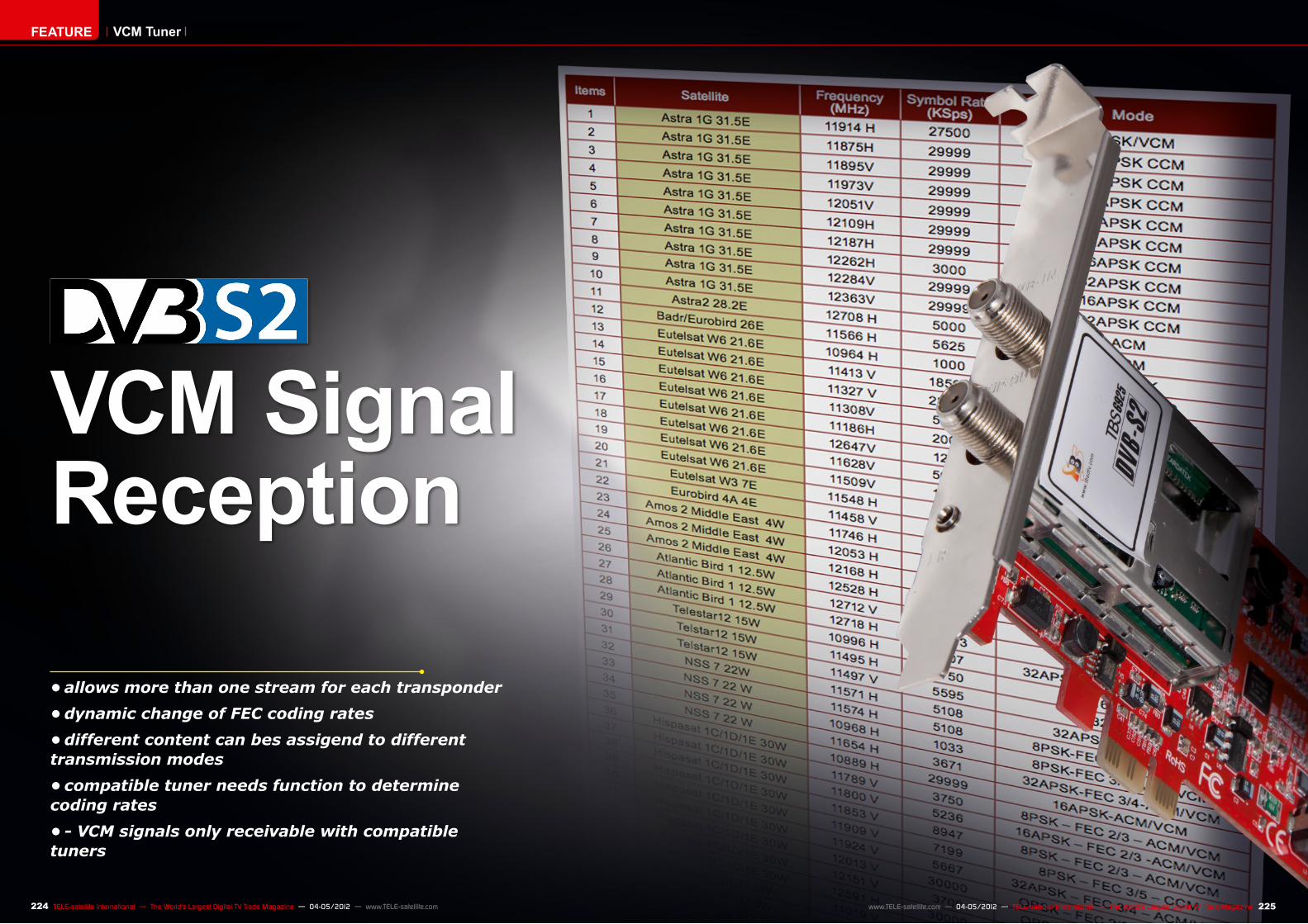
As already described in TELE-satel-lite (see issue 12-01/2012), there are already transponders transmitting in VCM and ACM format. However, there are still quite few receivers or receiver cards available today that can receive VCM signal. How does the tuner of such a receiver differ from its standard CCM brother? Before we discuss the receiver front end suitable for VCM transmis-sions, let us focus first on the transmit-ter part – DVB-S2 modulator. Figure 1 explains the principle of operation of a DVB-S2 modulator with MIS (Multi In-put Streams) feature.
VCM Tuner
Figure 1. DVB-S2 Modulator with MIS feature.
■ ■
1 2
228 229TELE-satellite International — The World‘s Largest Digital TV Trade Magazine — 04-05/2012 — www.TELE-satellite.com www.TELE-satellite.com — 04-05/2012 — TELE-satellite International — The World‘s Largest Digital TV Trade Magazine
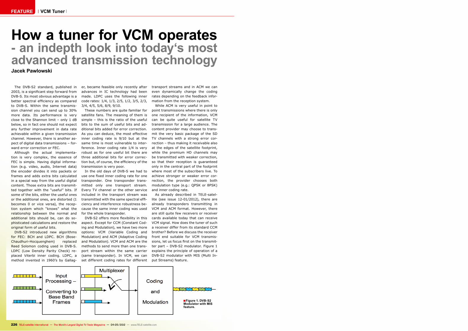
Three exemplary transport streams (yellow, green and blue) at the input of the modulator consist of rather short transport packets. The TS packets are converted to longer BB (Base Band) frames. They are either 16 or 64 kilo-bytes long. In fact, there are more op-erations done in this module (like mode adaptation, stream adaptation) but as they are not so relevant for understand-ing the principle of operation, there is no need to describe them here. Then, BB frames are time-multiplexed on the same carrier. In the process of coding, BB frames are appended with error cor-rection bits (see Figure 2). Depending on the user settings, LDPC coding rates can be different for different streams. When no data is present, the modulator pads incomplete BB frames or inserts
dummy BB frames if needed. Multi-plexed BB frames are then interleaved and modulated.
As mentioned earlier, each transport stream (converted to BB frames) can have its own modulation: QPSK, 8PSK, 16APSK or 32APSK and inner coding ratio.
Except for the BB header, DVB-S2 also uses PL (Physical Layer) headers. The PL header is always transmitted using a robust modulation and strong FEC rate. This helps the receiver lock on the signal, as well as it provides the information necessary to appropriately demodulate the remainder of the PL frame. The first thing the receiver does when tuned to a given frequency with a given symbol rate is looking for a PL header.
A block diagram of the reception sys-tem is shown in Figure 3. This is in fact a partial and simplified block diagram of a VCM compatible DVB-S2 receiver. Signal from an LNB is converted in the L-Band tuner to a pair of quadrature signals: I and Q, which are then con-verted to the digital domain in the dual analog-to-digital converter. Such archi-tecture is typical for most of the con-temporary RF devices – not only satel-lite TV receivers.
The DVB-S2 demodulator, after lock-ing and processing the PL header, learns what is inside the signal: how many different transport streams, what modulation they use and what their FEC settings are. At the output of the DVB-S2 demodulator we get BB frames along with additional error correction
bits. The next block takes care of er-ror correction and does descrambling if necessary. Unscrambled and error corrected BB frames are fed into the TS processor which turns them into familiar transport stream packets. The transport stream is then processed as in any DVB receiver – a desired TV’s or radio channel’s TS packets are filtered out and converted to a HDMI signal or to analog video and audio in digital-to-analog converters.
As you can see, the changes in hard-ware architecture are not so fundamen-tal but except for introducing them, also software must be re-written. For example, today’s receivers assume that one transponder carries just one trans-port stream with a given modulation and FEC ratio. New receivers must be
Figure 2. In the process of coding, BB frames are appended with error correction bits.
able to assign more than one transport stream to one transponder. From the end user’s perspective, a VCM DVB-S2 transponder is like a few classical DVB-S2 transponders overlapped one over another on the same frequency.
If you would like to transmit the VCM signal as a couple of ordinary CCM sig-nals, you would need as many classi-cal transponders as many transport
streams you use. And because such CCM transponders would have to be separated in frequency spectrum, the total bandwidth occupied by them would be greater than the bandwidth occupied by one VCM transponder. That’s the basic advantage of VCM.
The sky seems to be the limit for the excellence in satellite bandwidth utili-zation.
Fig. 3. Block diagram of VCM compatible DVB-S2 receiver front end.
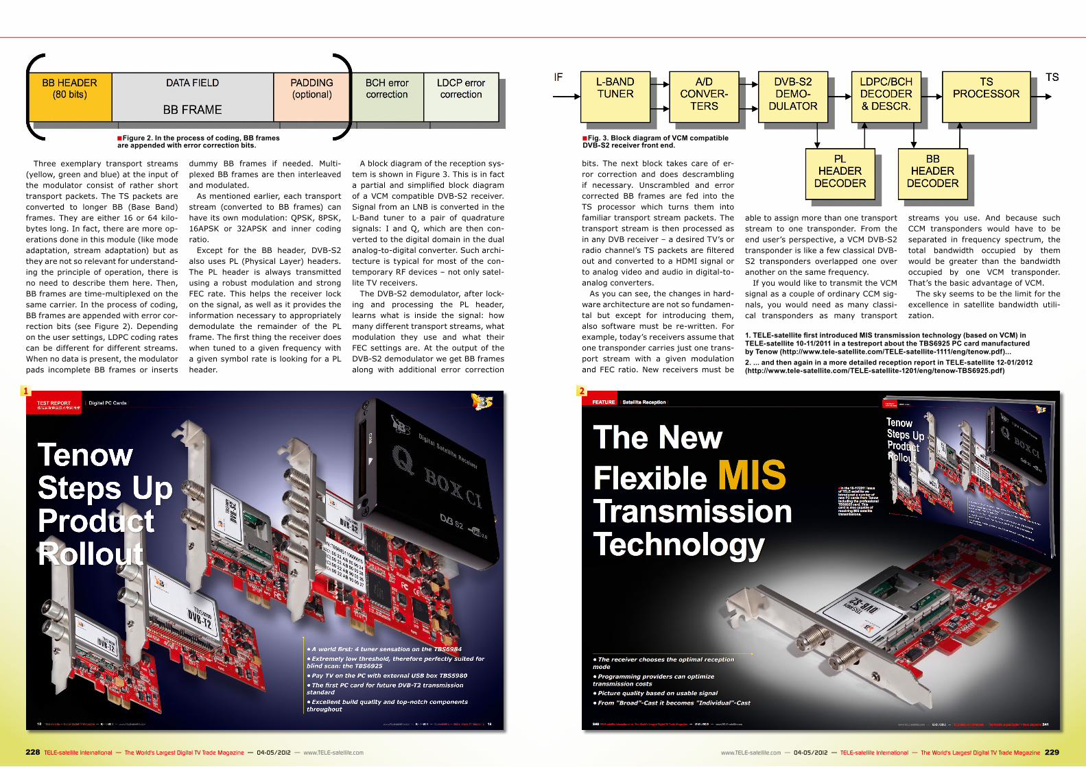
1. TELE-satellite first introduced MIS transmission technology (based on VCM) in TELE-satellite 10-11/2011 in a testreport about the TBS6925 PC card manufactured by Tenow (http://www.tele-satellite.com/TELE-satellite-1111/eng/tenow.pdf)... 2. ... and then again in a more detailed reception report in TELE-satellite 12-01/2012 (http://www.tele-satellite.com/TELE-satellite-1201/eng/tenow-TBS6925.pdf)