DUST COLLECTOR BAGHOUSE - CAMCORP, Inc. Info/Baghouse_Collector_IOM_Manual.pdf · DUST COLLECTOR...
38
DUST COLLECTOR BAGHOUSE INSTRUCTION, OPERATIONS & MAINTENANCE MANUAL CLEAN AIR MANAGEMENT COMPANY, INC. 8224 Nieman Road i Lenexa, Kansas 66214 Phone: 913-831-0740 Fax: 913-831-9271
Transcript of DUST COLLECTOR BAGHOUSE - CAMCORP, Inc. Info/Baghouse_Collector_IOM_Manual.pdf · DUST COLLECTOR...

DUST COLLECTOR BAGHOUSE
INSTRUCTION, OPERATIONS & MAINTENANCE MANUAL
CLEAN AIR MANAGEMENT COMPANY, INC. 8224 Nieman Road i Lenexa, Kansas 66214 Phone: 913-831-0740 Fax: 913-831-9271
TABLE OF CONTENTS
OPERATING PRINCIPAL ............................................................................................. 1-1 RECEIVING & INSPECTION OF UNIT....................................................................... 2-1 ON SITE STORAGE RECOMMENDATIONS ............................................................. 3-1 SETTING UP YOUR UNIT............................................................................................ 4-1 BAG & CAGE INSTALLATION................................................................................... 5-1 COMPRESSED AIR REGULATOR INSTALLATION INSTRUCTIONS .................. 6-1 START-UP CHECK LIST .............................................................................................. 7-1 START-UP DUST CONTROL SYSTEMS .................................................................... 8-1 SHUTDOWN PROCEDURES........................................................................................ 9-1 TROUBLE SHOOTING THE DUST COLLECTOR................................................... 10-1 TROUBLE SHOOTING THE TIMER ......................................................................... 11-1 TROUBLE SHOOTING THE COMPRESSED AIR SYSTEM................................... 12-1 SAFETY RECOMMENDATIONS............................................................................... 13-1 ROUTINE MAINTENANCE........................................................................................ 14-1
CLEAN AIR MANAGEMENT COMPANY, INC. 8224 Nieman Road i Lenexa, Kansas 66214 Phone: 913-831-0740 Fax: 913-831-9271
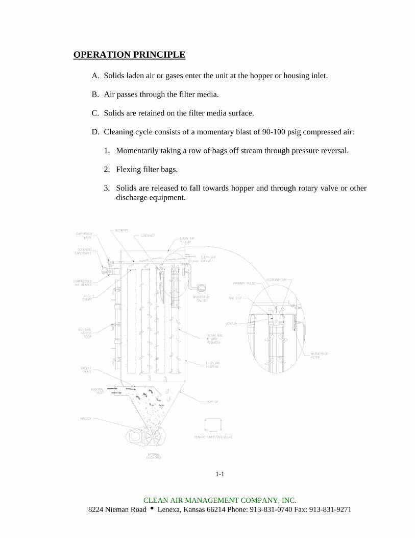
OPERATION PRINCIPLE
A. Solids laden air or gases enter the unit at the hopper or housing inlet.
B. Air passes through the filter media.
C. Solids are retained on the filter media surface.
D. Cleaning cycle consists of a momentary blast of 90-100 psig compressed air:
1. Momentarily taking a row of bags off stream through pressure reversal.
2. Flexing filter bags.
3. Solids are released to fall towards hopper and through rotary valve or other discharge equipment.
1-1
CLEAN AIR MANAGEMENT COMPANY, INC. 8224 Nieman Road i Lenexa, Kansas 66214 Phone: 913-831-0740 Fax: 913-831-9271
RECEIVING YOUR UNIT Prior to accepting shipment, care must be taken to inspect all equipment received both for proper count and for damage. Any and all irregularities must be noted on the carrier’s copy of the shipping receipt to assist in settling any claims for damage or shortages. All equipment is shipped FOB point of origin whether on a prepaid or collect freight basis. ANY CLAIM FOR DAMAGE IN TRANSIT OR SHORTAGES MUST BE BROUGHT AGAINST THE CARRIER BY THE PURCHASER. Once your claim has been filed with the carrier, contact CAMCORP to notify us of the problem(s) and then we will advise the appropriate repair procedure or recommend it to be returned to the factory depending on the extent of damage. INSPECTION OF UNIT Housing, Air Header and Timer Assembly: Particular attention should be paid to the sheet metal housing of your collector. The unit should be inspected for dents, cracks or rips. A dented housing may seriously affect the structural integrity of the unit. The air header and timer assembly are very delicate pieces of the unit and must be checked carefully for any signs of impact, warpage or loose fittings. If any of these signs are present, note them on the shipping receipt and notify CAMCORP immediately. The entire unit should be checked against the certified drawings for correctness and the manufacturer notified immediately if there are any discrepancies. No corrections may be made without the expressed written consent of CAMCORP.
Components: A count should be made of all pieces received and this should be verified against the carrier’s manifest. Boxes should be inspected for rough handling, which may have resulted in hidden damage.
2-1
CLEAN AIR MANAGEMENT COMPANY, INC. 8224 Nieman Road i Lenexa, Kansas 66214 Phone: 913-831-0740 Fax: 913-831-9271

ON SITE STORAGE RECOMMENDATIONS I. Baghouse, Bin Vent, Filter Receiver, Dirty Air Hopper and Housing
1. Housing can be stored outside. 2. Equipment must be blocked up to keep the flanges out of the dirt. 3. Many units are supplied with a plain finish bare steel interior. If storage of
more than two weeks is anticipated, the interior should be prime coated before storage.
4. Covering the unit with a tarp is recommended to keep the interior from rusting or corroding as well as keeping the outer finish in new condition. However, the tarp is not absolutely necessary.
II. Baghouse, Bin Vent, Filter Receiver, and Clean Air Plenum
1. Unit can be stored outside. 2. Air header and diaphragm valves must be tarped for weather protection. 3. Positioned unit so water will not get in or remain inside the tube sheet area. 4. Unit must be blocked up to keep the flanges, bag cups, venturis and air header
out of water and dirt. 5. Ports on diaphragm valves must be plugged and taped to keep insects, dirt and
moisture out. 6. For extended storage (more than 4 weeks), it is recommended to remove the
timer panel and solenoid assembly (if mounted). These components should be stored inside a cool dry area along with the copper or black nylon tubing. The solenoids should have all ports capped and taped to protect from insects, dirt and moisture.
7. The unit should be tarped but is not absolutely necessary. III. Bags & Cages
1. Bags must be stored inside a cool dry area protected from moisture, rodents and insects.
2. For extended storage the boxes for the bags should be wrapped with plastic wrap or stretch wrap to protect from moisture.
3. If the bags get wet for any reason, immediately lay them out with plenty of ventilation to dry in order to prevent mold and mildew.
4. It is recommended to store the cages inside a dry area if at all possible. 5. If an inside location is not available, cages can be stored outside as long as they
are covered by a tarp. 6. Cages are generally stored horizontally on pallets to keep them off the ground. 7. If cages can be stored horizontally, do not stack over three boxes high. 8. If the job site is in an area that may receive a significant snow load, the cages
must be stored vertically in order to prevent being crushed by the weight of the snow. Do not stack more than one box high
.3-1
CLEAN AIR MANAGEMENT COMPANY, INC. 8224 Nieman Road i Lenexa, Kansas 66214 Phone: 913-831-0740 Fax: 913-831-9271
ON SITE STORAGE RECOMMENDATIONS (continued) IV. Accessory Parts
1. This includes all gauges, bag clamps, nylon or copper tubing, valves, gaskets and other parts not specifically called out.
2. These items should be stored inside a cool dry place protected from moisture, insects and rodents.
V. Fan and Fan Accessories
1. Fans can be stored outside on a pallet or skid to keep them out of water and dirt. 2. Fan silencers, outlet dampers and inlet boxes should also be tarped and stored
on a pallet or skid. VI. Ducting
1. Ducting can be stored outside on a pallet or skid to keep it off the ground. It should be positioned so that water does not sit on or in the ducting.
2. If ducting is unpainted carbon steel, it should be at least primed coated before storage.
3. If ducting is already finish coated, it should be tarped to protect the finish but is not absolutely necessary.
VII. Knife Gate
1. All limit switches, solenoids and air cylinder ports must be capped and taped to prevent any moisture or dirt from entering.
2. Equipment can sit outside provided it is covered with a tarp and is on a pallet or skid to keep it out of water and dirt.
VIII. Isolation Dampers
1. All limit switches, solenoids and air cylinder ports must be capped and taped to prevent any moisture or dirt from entering.
2. Equipment can sit outside provided it is covered with a tarp and is on a pallet or skid to keep it out of water and dirt.
3-2
CLEAN AIR MANAGEMENT COMPANY, INC. 8224 Nieman Road i Lenexa, Kansas 66214 Phone: 913-831-0740 Fax: 913-831-9271
ON SITE STORAGE RECOMMENDATIONS (continued) IX. Rotary Valve
1. Rotor and interior of valve should be well oiled with vegetable oil to prevent rust and to maintain compatibility with product.
2. Unit can be stored outside provided it is covered with a tarp and is on a pallet or skid to keep it out of water and dirt.
X. Butterfly (Wafer Valve)
1. All limit switches, solenoids and air cylinder ports must be capped and taped to prevent any moisture or dirt from entering.
2. Unit can be stored outside provided it is covered with a tarp and is on a pallet or skid to keep it out of water, dirt and sunlight.
XI. Level Indicators
Store these items inside a protected cool dry area. XII. AC Inverters
Store these items and all other electrical controls inside a protected cool dry area.
3-3
CLEAN AIR MANAGEMENT COMPANY, INC. 8224 Nieman Road i Lenexa, Kansas 66214 Phone: 913-831-0740 Fax: 913-831-9271
SETTING UP YOUR UNIT CAMCORP dust collectors are shipped either in one piece, fully assembled or in two or more sections depending on the unit size and weight. Before attempting to move the dust collector or any of its sections, review both the certified general assembly drawing supplied from CAMCORP and the rigging and lifting guidelines included in this manual. Become familiar with the size and number of sections to be assembled, the orientation of inlet(s), outlet(s), access door(s) and compressed air header(s), as well as the number and location of lifting lugs. Dust collectors of this type are manufactured from steel sheets and are quite flexible. Therefore, even though care has been taken to maintain dimensional accuracy and squareness, some difficulty should be anticipated and temporary bracing in the field may be required. The following sequential procedure will help to minimize any assembly difficulties:
STEP 1: Set up the supporting steel for the dust collector level and square. Precision at this point will greatly help facilitate erection and bolt hole alignment of the dust collector sections to follow.
STEP 2: Place the hopper with its girth channel on the supporting steel work.
Check for squareness, and for bolthole alignment between the hopper flange and the girth channel. Apply the appropriate RTV silicone caulk around the periphery of the hopper flange, one bead on each side of the boltholes.
STEP 3: Lift the dusty air plenum, with the tube sheet, into place. DO NOT
LOWER THE PLENUM ONTO THE HOPPER FLANGE UNTIL ALIGNMENT IS ACCOMPLISHED. The silicone caulk makes horizontal movement very difficult once a load is applied. With the plenum suspended over the hopper ½” to 1”, begin bolt hole alignment, starting at the center of the plenum and working toward the ends by using tapered drift pins. If the wall(s) has flexed out of square, it will be necessary to pry or pull it back into alignment. Depending on the size of the unit and the degree of difficulty, hydraulic jacks and come-alongs may be required. When the mating holes are properly aligned, finish lowering the plenum. Install the remaining bolts, washers and nuts and torque to the appropriate specifications.
4-1
CLEAN AIR MANAGEMENT COMPANY, INC. 8224 Nieman Road i Lenexa, Kansas 66214 Phone: 913-831-0740 Fax: 913-831-9271
SETTING UP YOUR UNIT (continued)
STEP 4: Check the top of the dusty air plenum for squareness and bolthole alignment between the dusty air plenum and the tube sheet. Make sure that the silicone caulk has been applied between the top flange of the dusty air plenum and the underside of the tube sheet flange. Next, apply the caulk around the periphery of the topside of the tube sheet flange, one bead to each side of the boltholes.
STEP 5: Lift the clean air plenum into place and assemble in the same fashion as in
STEP 3. Again, do not lower the clean air plenum completely until preliminary alignment is accomplished. Start drift pin alignment at the center of the plenum on the compressed air header side since the header makes access to the flange more limited. When alignment is complete, install the remaining bolts, washers and nuts and torque to the appropriate specifications.
All CAMCORP dust collectors are provided with lifting lugs for ease in handling of the units during field erection and installation. The number and location of these lifting lugs will vary depending on the model, size and weight of the dust collector. Before attempting to rig and lift your dust collector, review the certified general assembly drawing supplied from CAMCORP to verify the number and location of lifting lugs, as well as visually checking this information on the actual unit. Large units are frequently shipped in several sections, so check the lifting lugs provided on each section. If these cannot be used or there is some question about lifting lug location, consult the engineering staff at CAMCORP for proper location since proper care must be taken to prevent damage to housing or it components.
Rigging and Lifting Guidelines 1. Do not lift the dust collector by any attachments other than the lifting lugs
provided.
2. Use all of the lifting lugs provided on the dust collector or a section of the dust collector, when making a lift.
3. If the lifting lugs are located below the roofline of the dust collector or below
the top of the section of the dust collector, a vertical pull must be made to avoid crushing the top of the unit. Use spreader beams to accomplish this vertical pull.
4-2
CLEAN AIR MANAGEMENT COMPANY, INC. 8224 Nieman Road i Lenexa, Kansas 66214 Phone: 913-831-0740 Fax: 913-831-9271
SETTING UP YOUR UNIT (continued)
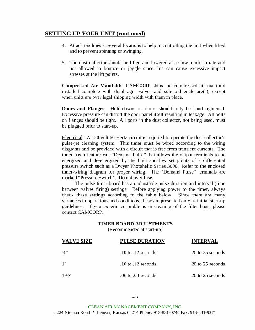
4. Attach tag lines at several locations to help in controlling the unit when lifted and to prevent spinning or swinging.
5. The dust collector should be lifted and lowered at a slow, uniform rate and
not allowed to bounce or joggle since this can cause excessive impact stresses at the lift points.
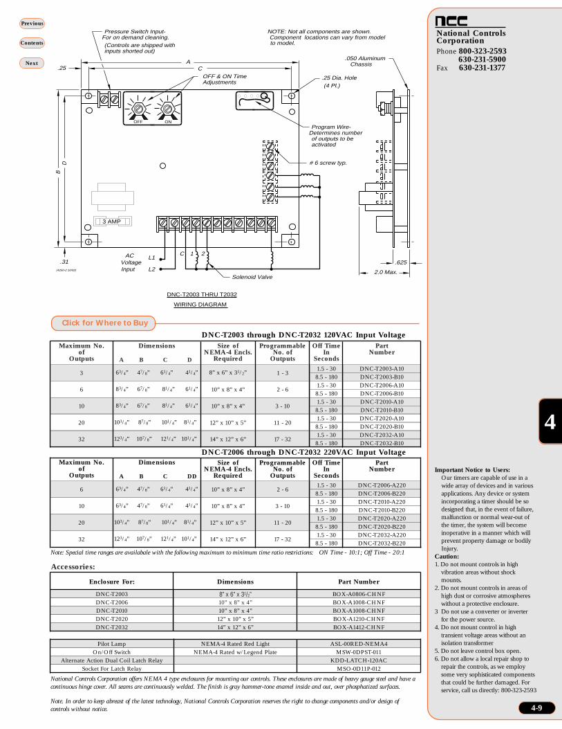
Compressed Air Manifold: CAMCORP ships the compressed air manifold installed complete with diaphragm valves and solenoid enclosure(s), except when units are over legal shipping width with them in place. Doors and Flanges: Hold-downs on doors should only be hand tightened. Excessive pressure can distort the door panel itself resulting in leakage. All bolts on flanges should be tight. All ports in the dust collector, not being used, must be plugged prior to start-up. Electrical: A 120 volt 60 Hertz circuit is required to operate the dust collector’s pulse-jet cleaning system. This timer must be wired according to the wiring diagrams and be provided with a circuit that is free from transient currents. The timer has a feature call “Demand Pulse” that allows the output terminals to be energized and de-energized by the high and low set points of a differential pressure switch such as a Dwyer Photohelic Series 3000. Refer to the enclosed timer-wiring diagram for proper wiring. The “Demand Pulse” terminals are marked “Pressure Switch”. Do not over fuse. The pulse timer board has an adjustable pulse duration and interval (time between valves firing) settings. Before applying power to the timer, always check these settings according to the table below. Since there are many variances in operations and conditions, these are presented only as initial start-up guidelines. If you experience problems in cleaning of the filter bags, please contact CAMCORP.
TIMER BOARD ADJUSTMENTS (Recommended at start-up)
VALVE SIZE PULSE DURATION INTERVAL ¾” .10 to .12 seconds 20 to 25 seconds 1” .10 to .12 seconds 20 to 25 seconds 1-½” .06 to .08 seconds 20 to 25 seconds
4-3
CLEAN AIR MANAGEMENT COMPANY, INC. 8224 Nieman Road i Lenexa, Kansas 66214 Phone: 913-831-0740 Fax: 913-831-9271

Phone 800-323-2593630-231-5900
Fax 630-231-1377
National ControlsCorporation
4
Contents
Previous
Next
4-8
Features■ File #E65038■ Digital Timing Circuitry:
Allows for stable timingfrom -40°F to 150°F temperaturerange
■ Pulse Time: Line synchro-nized to eliminate 8 mil-liseconds triac tum offvariation
■ 10 Amp-400/600V OutputTriacs: For maximum pro-tection against outputshorts. 200 VA load rating.
■ RTV Coating: Conformallycoated for protectionagainst vibration, humidi-ty and contamination
■ 2 Modes of Operation:Can be operated continu-ously or "on demand" viaexternal pressure switch
■ Field Selectable: For num-bers of outputs required
■ LED Indicators: For com-partment being cleanedindication
■ Rugged TimingAdjustments: Large stablepotentiometers are usedfor "on" and "off" timeadjustments
■ Metal Chassis Provided:For mounting directly into NEMA-4 box
■ Timer Life Tested for 24Hours: To eliminate fieldfailures
■ Input Protection: 30 joulemetal oxide varistor
■ One Year Warranty:Warranted to be free fromdefects in materials orworkmanship for OneYear from date of purchase
■ Made in USA
CRR
Dust CollectorControls
Operating Logic: The control can function in 2modes:
Continuous Mode: The pressure switch termi-nals are shorted. Upon application of input volt-age, the control activates output #1 after the pre-set off time. It will continue to activate outputssequentially until input voltage is removed.
On Demand Mode: The pressure switch termi-nals are connected to an isolated set of contacts ofa differential pressure switch. The control willactivate the outputs sequentially whenever thepressure switch contacts are closed. When thepressure switch contacts open, the outputsequencing stops. Re-closing of the contacts willcause the control to resume activating the out-puts.
Program wire allows the user to select the maxi-mum number of outputs to be activated. Note: Controls are shipped with jumper across pressure switch terminals
AC Input, PulseCleaning of BagHouse DustCollectors Models DNC-T2003thru DNC-T2032
L1 L2 1 2 3 4 5 6 7 8 9 10C
Pressureswitch TIMER #1
voltageInput
120V
LastSolenoid
S
SSolenoid
Last
TIMER #2
C 10987654321L2L1
Pressure switch
3867-1
dual coil latching relay.
reset coil energized last.
11
4
Contacts shown with
8
13 9
COM
coilReset
12
coilSet
N.C.
COM
1
N.C.
N.O.
N.O.
510
14
Alternate action
To expand the number of outputs in "continuouscleaning mode", any two timers can be connected viaa dual coil alternate action latch relay as shown inthe diagram to the right.
The output pulse from the last compartment of TimerNo. 1 activates the latch coil opening the reset contactsconnected to pressure switch terminals of Timer No. 1,causing Timer No 1 to stop sequencing. At the sametime, the latch contacts connected to pressure switchTimer No. 2 close which will cause Timer No. 2 tostart sequencing until the last output activation causesthe reset coil to unlatch the relay and Timer No. 1begins sequencing. This cycle will continue untilvoltage is removed from the system.
Wiring diagram to FacilitateExpanded Output Mode
Time Delay On-Time: Adjustable from 50 to 500 millisec-
onds Off-Time: Range A - adjustable from 1.5 to 30
seconds; Range B - adjustable from 8.5 to 180seconds
Note: Range S designates customer specified timerange. Consult factory for parameters
Repeatability: ± 3% over temperature and volt-age ranges
InputOperating Voltage:
120 ± 10%, 220 ±10% VACFrequency: 50/60 HzPower Consumption: 2 VA Max.
OutputType: Solid-state switch (Triac)Switch Rating: 200 VA maximum per output
ProtectionTransient Voltage: 30 joule metal oxide varistorShort Circuit Protection: 3 Amp. fuse
EnvironmentalOperating Temperature: -40°C to 66°CStorage Temperature: -40°C to 70°C
Specifications
Phone 800-323-2593630-231-5900
Fax 630-231-1377
National ControlsCorporation
4
Contents
Previous
Next
4-9
8” x 6” x 31/2”10” x 8” x 4”
Accessories:
CA
DB
.25
.31
.25 Dia. Hole(4 Pl.)
L1
L2
AC VoltageInput
C 1 2
Solenoid Valve
OFF & ON TimeAdjustments
Program Wire- Determines number
of outputs to beactivated
Pressure Switch Input- For on demand cleaning.
(Controls are shipped withinputs shorted out)
(4250-2 10/92)
.625
2.0 Max.
.050 Aluminum Chassis
NOTE: Not all components are shown. Component locations can vary from modelto model.
DNC-T2003 THRU T2032
OFF ON
3 AMP
# 6 screw typ.
WIRING DIAGRAM
Maximum No.of
Outputs
Dimensions
A B C D
Size ofNEMA-4 Encls.
Required
Programmable No. of
Outputs
Off Time In
Seconds
Part Number
3 63/4” 47/8” 61/4” 41/4” 8” x 6” x 31/2” 1 - 31.5 - 30 DNC-T2003-A108.5 - 180 DNC-T2003-B10
6 83/4” 67/8” 81/4” 61/4” 10” x 8” x 4” 2 - 61.5 - 30 DNC-T2006-A108.5 - 180 DNC-T2006-B10
10 83/4” 67/8” 81/4” 61/4” 10” x 8” x 4” 3 - 101.5 - 30 DNC-T2010-A108.5 - 180 DNC-T2010-B10
20 103/4” 87/8” 101/4” 81/4” 12” x 10” x 5” 11 - 201.5 - 30 DNC-T2020-A108.5 - 180 DNC-T2020-B10
32 123/4” 107/8” 121/4” 101/4” 14” x 12” x 6” 17 - 321.5 - 30 DNC-T2032-A108.5 - 180 DNC-T2032-B10
Maximum No.of
Outputs
Dimensions
A B C DD
Size ofNEMA-4 Encls.
Required
Programmable No. of
Outputs
Off Time In
Seconds
Part Number
6 63/4” 47/8” 61/4” 41/4” 10” x 8” x 4” 2 - 61.5 - 30 DNC-T2006-A2208.5 - 180 DNC-T2006-B220
10 63/4” 47/8” 61/4” 41/4” 10” x 8” x 4” 3 - 101.5 - 30 DNC-T2010-A2208.5 - 180 DNC-T2010-B220
20 103/4” 87/8” 101/4” 81/4” 12” x 10” x 5” 11 - 201.5 - 30 DNC-T2020-A2208.5 - 180 DNC-T2020-B220
32 123/4” 107/8” 121/4” 101/4” 14” x 12” x 6” 17 - 321.5 - 30 DNC-T2032-A2208.5 - 180 DNC-T2032-B220
DNC-T2003 through DNC-T2032 120VAC Input Voltage
DNC-T2006 through DNC-T2032 220VAC Input Voltage
Enclosure For: Dimensions Part Number
DNC-T2003 BOX-A0806-CHNFDNC-T2006 BOX-A1008-CHNFDNC-T2010 10” x 8” x 4” BOX-A1008-CHNFDNC-T2020 12” x 10” x 5” BOX-A1210-CHNFDNC-T2032 14” x 12” x 6” BOX-A1412-CHNF
Pilot Lamp NEMA-4 Rated Red Light ASL-00RED-NEMA4On/Off Switch NEMA-4 Rated w/Legend Plate MSW-0DPST-011
Alternate Action Dual Coil Latch Relay KDD-LATCH-120ACSocket For Latch Relay MSO-0D11P-012
National Controls Corporation offers NEMA 4 type enclosures for mounting our controls. These enclosures are made of heavy gauge steel and have acontinuous hinge cover. All seams are continuously welded. The finish is gray hammer-tone enamel inside and out, over phosphatized surfaces.
Note. In order to keep abreast of the latest technology, National Controls Corporation reserves the right to change components and/or design ofcontrols without notice.
Note: Special time ranges are availabale with the following maximum to minimum time ratio restrictions: ON Time - 10:1; Off Time - 20:1
Important Notice to Users:Our timers are capable of use in awide array of devices and in variousapplications. Any device or systemincorporating a timer should be sodesigned that, in the event of failure,malfunction or normal wear-out ofthe timer, the system will becomeinoperative in a manner which willprevent property damage or bodilyInjury.
Caution:1. Do not mount controls in high
vibration areas without shockmounts.
2. Do not mount controls in areas ofhigh dust or corrosive atmosphereswithout a protective enclosure.
3 Do not use a converter or inverterfor the power source.
4. Do not mount control in hightransient voltage areas without anisolation transformer
5. Do not leave control box open. 6. Do not allow a local repair shop to
repair the controls, as we employsome very sophisticated componentsthat could be further damaged. Forservice, call us directly: 800-323-2593
Click for Where to Buy
SETTING UP YOUR UNIT (continued)
The firing sequence of the diaphragm valves on the dust collector should be set so that no two adjacent rows of bags fire in succession to insure maximum cleaning and life of the filter media. This can only be achieved when wiring the pulse timer board to the solenoid valves. If you are experience a high-pressure drop across the filter bags in your dust collector, the pulse interval should be reduced. Apply electrical power to the timer and make sure that it is cycling completely through all rows of the unit. In some cases, the timer panel may have more “positions” than required, in which case, the position selector cable needs to be attached to the proper numerical value corresponding to the number of diaphragm valves on the unit. If your dust collector was shipped via common carrier rather than a contract hauler, there is a possibility that the solenoid enclosure was not shipped installed on the unit. If this is the case, there is a mounting plate welded on the housing or the air header with the bolt pattern of the enclosure already drilled. Bolt the enclosure and install the nylon (or copper) tubing with the fittings provided, making sure that the solenoids are hooked to their corresponding diaphragm valve. Valves and Piping: After the unit has been installed, the diaphragm valves should be checked to make sure that the port marked “IN” is assembled to the compressed air manifold. The “IN” connection of the solenoid valve is connected to the diaphragm valve by means of ¼” nylon or ¼” copper refrigeration tubing. Each nut on the brass compression fittings should be checked for tightness before the compressed air manifold is pressurized. In most cases a slip fit fitting has been used. The integrity of the nylon tubing inside each fitting should be checked by pulling gently on each tube. If the tube pulls out, simply push it back into the fitting until it will not go any further. The solenoids are shipped with a plastic plug in the discharge side of the valve. These plugs must be removed for proper operation. Gauges: The differential pressure gauge, mounting bracket, fittings and tubing are usually shipped loose in a box with the dust collector. When installing, make sure that the high-pressure port of the gauge is connected below the tube sheet and the low-pressure port is connected above the tube sheet on the dust collector. There are pipe couplings welded on the side of the dust collector for these connections. After the differential pressure gauge is permanently mounted, the gauge needs to be zeroed prior to connecting the tubing to the gauge. Auxiliary Equipment: All auxiliary equipment must be installed according to its manufacturer’s specifications and interlocked with the entire system as needed. Direction of rotation of each item must be checked prior to start-up of the entire system.
4-4
CLEAN AIR MANAGEMENT COMPANY, INC. 8224 Nieman Road i Lenexa, Kansas 66214 Phone: 913-831-0740 Fax: 913-831-9271
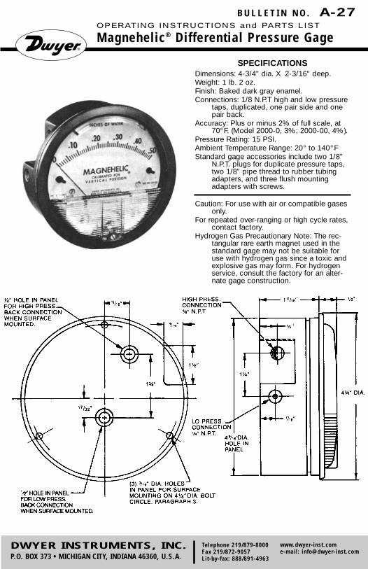
SPECIFICATIONSDimensions: 4-3/4" dia. X 2-3/16" deep.Weight: 1 lb. 2 oz.Finish: Baked dark gray enamel.Connections: 1/8 N.P.T high and low pressure
taps, duplicated, one pair side and onepair back.
Accuracy: Plus or minus 2% of full scale, at70°F. (Model 2000-0, 3%; 2000-00, 4%).
Pressure Rating: 15 PSI.Ambient Temperature Range: 20° to 140°FStandard gage accessories include two 1/8"
N.P.T. plugs for duplicate pressure taps,two 1/8" pipe thread to rubber tubingadapters, and three flush mountingadapters with screws.
Caution: For use with air or compatible gasesonly.
For repeated over-ranging or high cycle rates,contact factory.
Hydrogen Gas Precautionary Note: The rec-tangular rare earth magnet used in thestandard gage may not be suitable foruse with hydrogen gas since a toxic andexplosive gas may form. For hydrogenservice, consult the factory for an alter-nate gage construction.
B U L L E T I N N O . A-27OPERATING INSTRUCTIONS and PARTS LIST
Magnehelic® Differential Pressure Gage
DWYER INSTRUMENTS, INC.P.O. BOX 373 • MICHIGAN CITY, INDIANA 46360, U.S.A.
Telephone 219/879-8000Fax 219/872-9057Lit-by-fax: 888/891-4963
www.dwyer-inst.come-mail: [email protected]
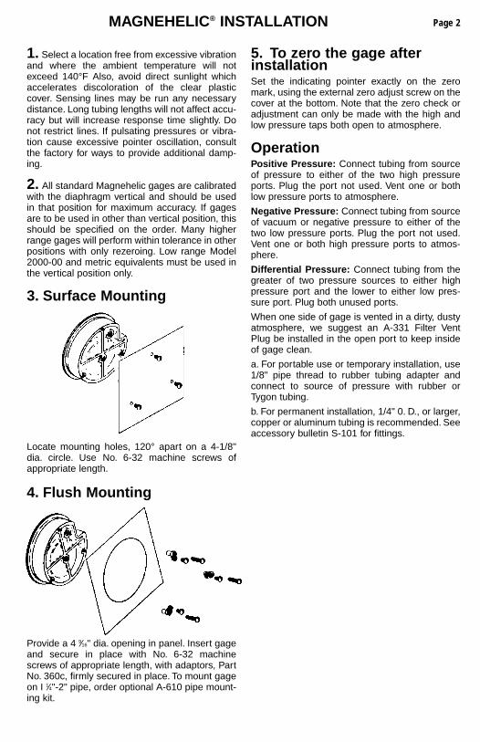
MAGNEHELIC® INSTALLATION
1. Select a location free from excessive vibrationand where the ambient temperature will notexceed 140°F Also, avoid direct sunlight whichaccelerates discoloration of the clear plasticcover. Sensing lines may be run any necessarydistance. Long tubing lengths will not affect accu-racy but will increase response time slightly. Donot restrict lines. If pulsating pressures or vibra-tion cause excessive pointer oscillation, consultthe factory for ways to provide additional damp-ing.
2. All standard Magnehelic gages are calibratedwith the diaphragm vertical and should be usedin that position for maximum accuracy. If gagesare to be used in other than vertical position, thisshould be specified on the order. Many higherrange gages will perform within tolerance in otherpositions with only rezeroing. Low range Model2000-00 and metric equivalents must be used inthe vertical position only.
3. Surface Mounting
Locate mounting holes, 120° apart on a 4-1/8"dia. circle. Use No. 6-32 machine screws ofappropriate length.
4. Flush Mounting
Provide a 4 9⁄16" dia. opening in panel. Insert gageand secure in place with No. 6-32 machinescrews of appropriate length, with adaptors, PartNo. 360c, firmly secured in place. To mount gageon I 1⁄4"-2" pipe, order optional A-610 pipe mount-ing kit.
5. To zero the gage afterinstallationSet the indicating pointer exactly on the zeromark, using the external zero adjust screw on thecover at the bottom. Note that the zero check oradjustment can only be made with the high andlow pressure taps both open to atmosphere.
OperationPositive Pressure: Connect tubing from sourceof pressure to either of the two high pressureports. Plug the port not used. Vent one or bothlow pressure ports to atmosphere.
Negative Pressure: Connect tubing from sourceof vacuum or negative pressure to either of thetwo low pressure ports. Plug the port not used.Vent one or both high pressure ports to atmos-phere.
Differential Pressure: Connect tubing from thegreater of two pressure sources to either highpressure port and the lower to either low pres-sure port. Plug both unused ports.
When one side of gage is vented in a dirty, dustyatmosphere, we suggest an A-331 Filter VentPlug be installed in the open port to keep insideof gage clean.
a. For portable use or temporary installation, use1/8" pipe thread to rubber tubing adapter andconnect to source of pressure with rubber orTygon tubing.
b. For permanent installation, 1/4" 0. D., or larger,copper or aluminum tubing is recommended. Seeaccessory bulletin S-101 for fittings.
Page 2
MAINTENANCEBULLETIN NO. A-27
Page 3
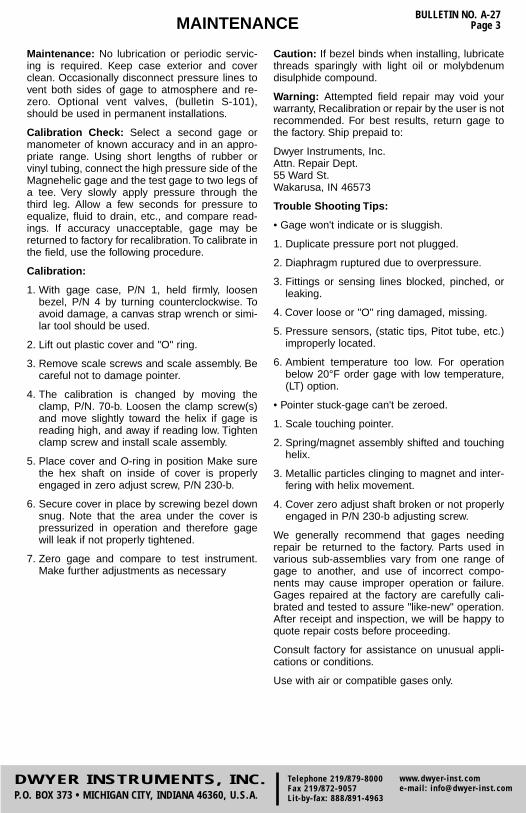
Maintenance: No lubrication or periodic servic-ing is required. Keep case exterior and coverclean. Occasionally disconnect pressure lines tovent both sides of gage to atmosphere and re-zero. Optional vent valves, (bulletin S-101),should be used in permanent installations.
Calibration Check: Select a second gage ormanometer of known accuracy and in an appro-priate range. Using short lengths of rubber orvinyl tubing, connect the high pressure side of theMagnehelic gage and the test gage to two legs ofa tee. Very slowly apply pressure through thethird leg. Allow a few seconds for pressure toequalize, fluid to drain, etc., and compare read-ings. If accuracy unacceptable, gage may bereturned to factory for recalibration. To calibrate inthe field, use the following procedure.
Calibration:
1. With gage case, P/N 1, held firmly, loosenbezel, P/N 4 by turning counterclockwise. Toavoid damage, a canvas strap wrench or simi-lar tool should be used.
2. Lift out plastic cover and "O" ring.
3. Remove scale screws and scale assembly. Becareful not to damage pointer.
4. The calibration is changed by moving theclamp, P/N. 70-b. Loosen the clamp screw(s)and move slightly toward the helix if gage isreading high, and away if reading low. Tightenclamp screw and install scale assembly.
5. Place cover and O-ring in position Make surethe hex shaft on inside of cover is properlyengaged in zero adjust screw, P/N 230-b.
6. Secure cover in place by screwing bezel downsnug. Note that the area under the cover ispressurized in operation and therefore gagewill leak if not properly tightened.
7. Zero gage and compare to test instrument.Make further adjustments as necessary
Caution: If bezel binds when installing, lubricatethreads sparingly with light oil or molybdenumdisulphide compound.
Warning: Attempted field repair may void yourwarranty, Recalibration or repair by the user is notrecommended. For best results, return gage tothe factory. Ship prepaid to:
Dwyer Instruments, Inc.Attn. Repair Dept.55 Ward St.Wakarusa, IN 46573
Trouble Shooting Tips:
• Gage won't indicate or is sluggish.
1. Duplicate pressure port not plugged.
2. Diaphragm ruptured due to overpressure.
3. Fittings or sensing lines blocked, pinched, orleaking.
4. Cover loose or "O" ring damaged, missing.
5. Pressure sensors, (static tips, Pitot tube, etc.)improperly located.
6. Ambient temperature too low. For operationbelow 20°F order gage with low temperature,(LT) option.
• Pointer stuck-gage can't be zeroed.
1. Scale touching pointer.
2. Spring/magnet assembly shifted and touchinghelix.
3. Metallic particles clinging to magnet and inter-fering with helix movement.
4. Cover zero adjust shaft broken or not properlyengaged in P/N 230-b adjusting screw.
We generally recommend that gages needingrepair be returned to the factory. Parts used invarious sub-assemblies vary from one range ofgage to another, and use of incorrect compo-nents may cause improper operation or failure.Gages repaired at the factory are carefully cali-brated and tested to assure "like-new" operation.After receipt and inspection, we will be happy toquote repair costs before proceeding.
Consult factory for assistance on unusual appli-cations or conditions.
Use with air or compatible gases only.
DWYER INSTRUMENTS, INC.P.O. BOX 373 • MICHIGAN CITY, INDIANA 46360, U.S.A.
Telephone 219/879-8000Fax 219/872-9057Lit-by-fax: 888/891-4963
www.dwyer-inst.come-mail: [email protected]
BULLETIN NO. A-27Page 4
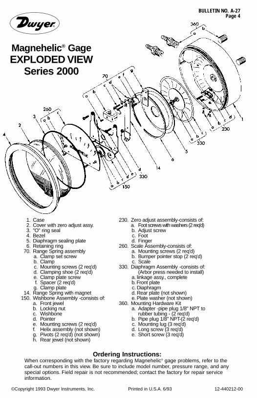
Magnehelic® GageEXPLODED VIEW
Series 2000
Ordering Instructions:When corresponding with the factory regarding Magnehelic® gage problems, refer to thecall-out numbers in this view. Be sure to include model number, pressure range, and anyspecial options. Field repair is not recommended; contact the factory for repair serviceinformation.
©Copyright 1993 Dwyer Instruments, Inc. Printed in U.S.A. 6/93 12-440212-00
1. Case2. Cover with zero adjust assy.3. "O" ring seal4. Bezel5. Diaphragm sealing plate6. Retaining ring
70. Range Spring assemblya. Clamp set screwb. Clampc. Mounting screws (2 req'd)d. Clamping shoe (2 req'd)e. Clamp plate screwf. Spacer (2 req'd)
g. Clamp plate14. Range Spring with magnet
150. Wishbone Assembly -consists of:a. Front jewelb. Locking nutc. Wishboned. Pointere. Mounting screws (2 req'd)f. Helix assembly (not shown)g. Pivots (2 req'd) (not shown)h. Rear jewel (not shown)
230. Zero adjust assembly-consists of:a. Foot screws with washers (2 req'd)b. Adjust screwc. Footd. Finger
260. Scale Assembly-consists of:a. Mounting screws (2 req'd)b. Bumper pointer stop (2 req'd)c. Scale
330. Diaphragm Assembly -consists of:(Arbor press needed to install)
a. linkage assy., complete b. Front plate c. Diaphragm d. Rear plate (not shown) e. Plate washer (not shown)
360. Mounting Hardware Kit a. Adapter -pipe plug 1/8" NPT to
rubber tubing - (2 req'd) b. Pipe plug 1/8" NPT-(2 req'd) c. Mounting lug (3 req'd) d. Long screw (3 req'd) e. Short screw (3 req'd)
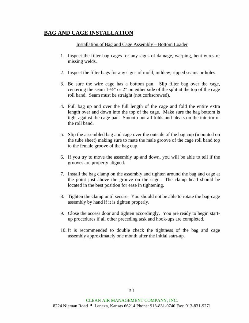
BAG AND CAGE INSTALLATION
Installation of Bag and Cage Assembly – Bottom Loader
1. Inspect the filter bag cages for any signs of damage, warping, bent wires or missing welds.
2. Inspect the filter bags for any signs of mold, mildew, ripped seams or holes.
3. Be sure the wire cage has a bottom pan. Slip filter bag over the cage,
centering the seam 1-½” or 2” on either side of the split at the top of the cage roll band. Seam must be straight (not corkscrewed).
4. Pull bag up and over the full length of the cage and fold the entire extra
length over and down into the top of the cage. Make sure the bag bottom is tight against the cage pan. Smooth out all folds and pleats on the interior of the roll band.
5. Slip the assembled bag and cage over the outside of the bag cup (mounted on
the tube sheet) making sure to mate the male groove of the cage roll band top to the female groove of the bag cup.
6. If you try to move the assembly up and down, you will be able to tell if the
grooves are properly aligned.
7. Install the bag clamp on the assembly and tighten around the bag and cage at the point just above the groove on the cage. The clamp head should be located in the best position for ease in tightening.
8. Tighten the clamp until secure. You should not be able to rotate the bag-cage
assembly by hand if it is tighten properly.
9. Close the access door and tighten accordingly. You are ready to begin start-up procedures if all other preceding task and hook-ups are completed.
10. It is recommended to double check the tightness of the bag and cage
assembly approximately one month after the initial start-up.
5-1
CLEAN AIR MANAGEMENT COMPANY, INC. 8224 Nieman Road i Lenexa, Kansas 66214 Phone: 913-831-0740 Fax: 913-831-9271
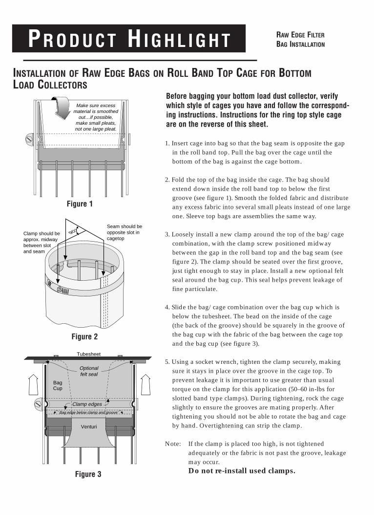
PR O D U C T HI G H L I G H T
INSTALLATION OF RAW EDGE BAGS ON ROLL BAND TOP CAGE FOR BOTTOMLOAD COLLECTORS
Before bagging your bottom load dust collector, verifywhich style of cages you have and follow the correspond-ing instructions. Instructions for the ring top style cageare on the reverse of this sheet.
1. Insert cage into bag so that the bag seam is opposite the gapin the roll band top. Pull the bag over the cage until the bottom of the bag is against the cage bottom.
2. Fold the top of the bag inside the cage. The bag shouldextend down inside the roll band top to below the firstgroove (see figure 1). Smooth the folded fabric and distributeany excess fabric into several small pleats instead of one largeone. Sleeve top bags are assemblies the same way.
3. Loosely install a new clamp around the top of the bag/cagecombination, with the clamp screw positioned midway between the gap in the roll band top and the bag seam (seefigure 2). The clamp should be seated over the first groove,just tight enough to stay in place. Install a new optional feltseal around the bag cup. This seal helps prevent leakage offine particulate.
4. Slide the bag/cage combination over the bag cup which isbelow the tubesheet. The bead on the inside of the cage (the back of the groove) should be squarely in the groove ofthe bag cup with the fabric of the bag between the cage topand the bag cup (see figure 3).
5. Using a socket wrench, tighten the clamp securely, makingsure it stays in place over the groove in the cage top. To prevent leakage it is important to use greater than usualtorque on the clamp for this application (50–60 in-lbs for slotted band type clamps). During tightening, rock the cageslightly to ensure the grooves are mating properly. Aftertightening you should not be able to rotate the bag and cageby hand. Overtightening can strip the clamp.
Note: If the clamp is placed too high, is not tightened adequately or the fabric is not past the groove, leakage may occur. Do not re-install used clamps.
Make sure excessmaterial is smoothed
out…if possible,make small pleats,not one large pleat.
90°Seam should be opposite slot in cagetop
Clamp should beapprox. midwaybetween slot and seam
BagCup
Venturi
Tubesheet
Optionalfelt seal
Bag edge below clamp and groove
Clamp edges
Figure 1
Figure 2
Figure 3
RAW EDGE FILTER
BAG INSTALLATION
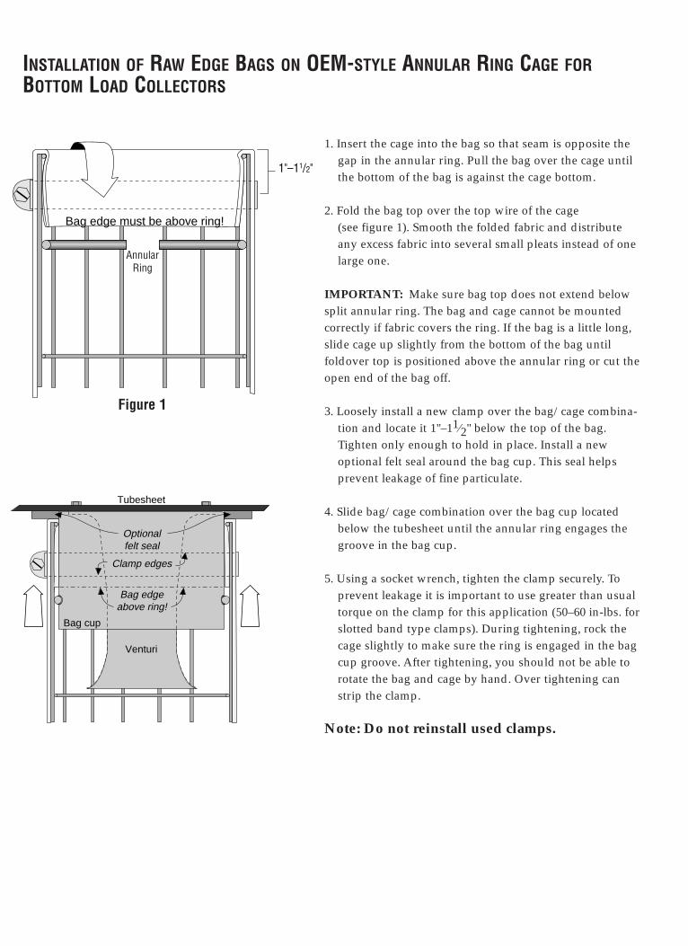
INSTALLATION OF RAW EDGE BAGS ON OEM-STYLE ANNULAR RING CAGE FORBOTTOM LOAD COLLECTORS
1. Insert the cage into the bag so that seam is opposite thegap in the annular ring. Pull the bag over the cage untilthe bottom of the bag is against the cage bottom.
2. Fold the bag top over the top wire of the cage (see figure 1). Smooth the folded fabric and distributeany excess fabric into several small pleats instead of onelarge one.
IMPORTANT: Make sure bag top does not extend belowsplit annular ring. The bag and cage cannot be mountedcorrectly if fabric covers the ring. If the bag is a little long,slide cage up slightly from the bottom of the bag untilfoldover top is positioned above the annular ring or cut theopen end of the bag off.
3. Loosely install a new clamp over the bag/cage combina-tion and locate it 1"–11⁄2" below the top of the bag. Tighten only enough to hold in place. Install a newoptional felt seal around the bag cup. This seal helps prevent leakage of fine particulate.
4. Slide bag/cage combination over the bag cup locatedbelow the tubesheet until the annular ring engages thegroove in the bag cup.
5. Using a socket wrench, tighten the clamp securely. Toprevent leakage it is important to use greater than usualtorque on the clamp for this application (50–60 in-lbs. forslotted band type clamps). During tightening, rock thecage slightly to make sure the ring is engaged in the bagcup groove. After tightening, you should not be able torotate the bag and cage by hand. Over tightening canstrip the clamp.
Note: Do not reinstall used clamps.
Bag edge must be above ring!
1"–11/2"
Figure 1
Bag edgeabove ring!
Clamp edges
Bag cup
Venturi
Tubesheet
Optionalfelt seal
Annular Ring
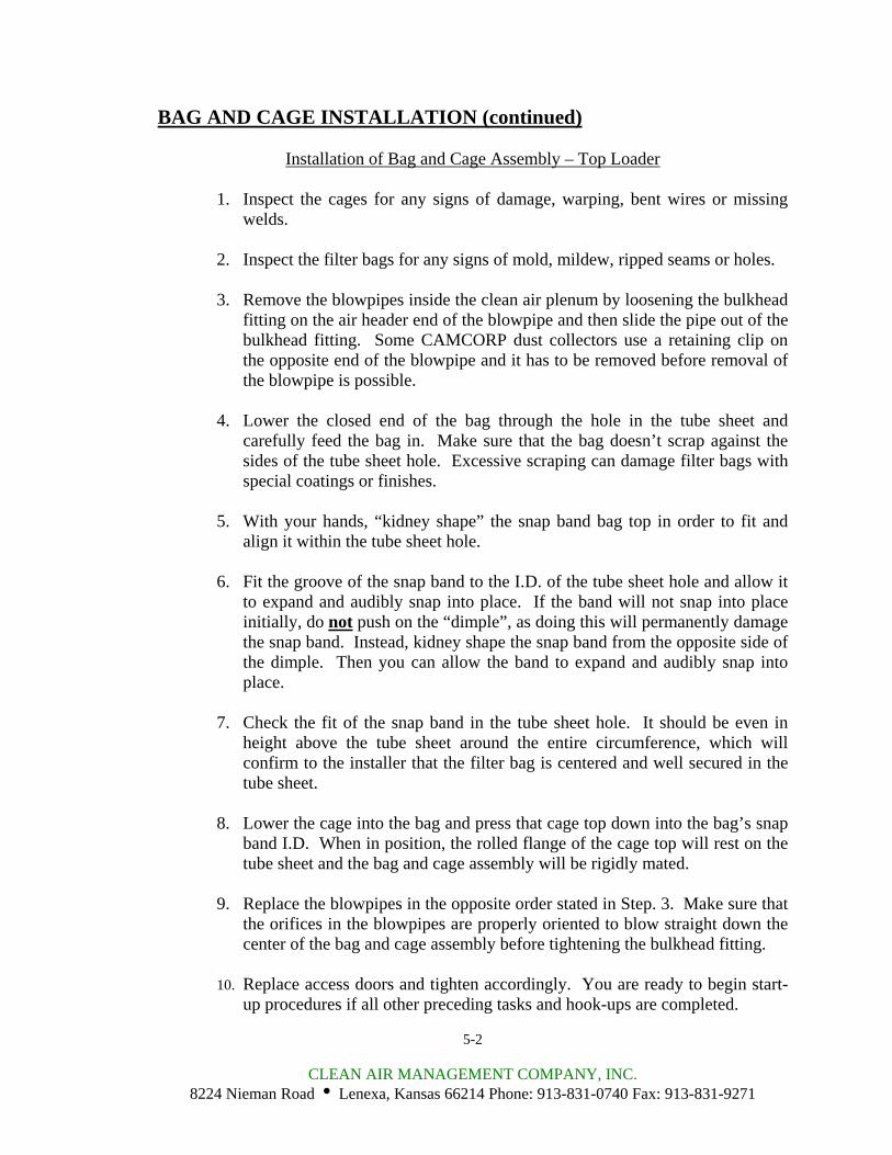
BAG AND CAGE INSTALLATION (continued)
Installation of Bag and Cage Assembly – Top Loader
1. Inspect the cages for any signs of damage, warping, bent wires or missing welds.
2. Inspect the filter bags for any signs of mold, mildew, ripped seams or holes.
3. Remove the blowpipes inside the clean air plenum by loosening the bulkhead
fitting on the air header end of the blowpipe and then slide the pipe out of the bulkhead fitting. Some CAMCORP dust collectors use a retaining clip on the opposite end of the blowpipe and it has to be removed before removal of the blowpipe is possible.
4. Lower the closed end of the bag through the hole in the tube sheet and
carefully feed the bag in. Make sure that the bag doesn’t scrap against the sides of the tube sheet hole. Excessive scraping can damage filter bags with special coatings or finishes.
5. With your hands, “kidney shape” the snap band bag top in order to fit and
align it within the tube sheet hole.
6. Fit the groove of the snap band to the I.D. of the tube sheet hole and allow it to expand and audibly snap into place. If the band will not snap into place initially, do not push on the “dimple”, as doing this will permanently damage the snap band. Instead, kidney shape the snap band from the opposite side of the dimple. Then you can allow the band to expand and audibly snap into place.
7. Check the fit of the snap band in the tube sheet hole. It should be even in
height above the tube sheet around the entire circumference, which will confirm to the installer that the filter bag is centered and well secured in the tube sheet.
8. Lower the cage into the bag and press that cage top down into the bag’s snap
band I.D. When in position, the rolled flange of the cage top will rest on the tube sheet and the bag and cage assembly will be rigidly mated.
9. Replace the blowpipes in the opposite order stated in Step. 3. Make sure that
the orifices in the blowpipes are properly oriented to blow straight down the center of the bag and cage assembly before tightening the bulkhead fitting.
10. Replace access doors and tighten accordingly. You are ready to begin start-
up procedures if all other preceding tasks and hook-ups are completed.
5-2
CLEAN AIR MANAGEMENT COMPANY, INC. 8224 Nieman Road i Lenexa, Kansas 66214 Phone: 913-831-0740 Fax: 913-831-9271
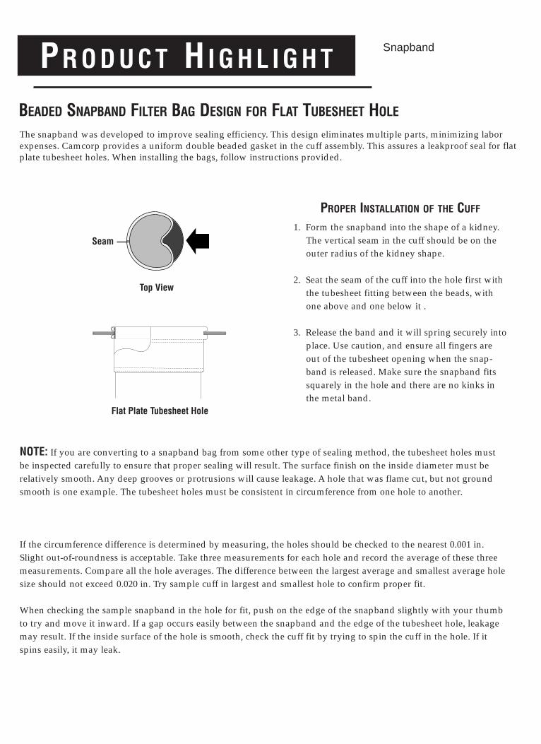
PR O D U C T HI G H L I G H T
BEADED SNAPBAND FILTER BAG DESIGN FOR FLAT TUBESHEET HOLE
The snapband was developed to improve sealing efficiency. This design eliminates multiple parts, minimizing laborexpenses. Camcorp provides a uniform double beaded gasket in the cuff assembly. This assures a leakproof seal for flatplate tubesheet holes. When installing the bags, follow instructions provided.
PROPER INSTALLATION OF THE CUFF
1. Form the snapband into the shape of a kidney.The vertical seam in the cuff should be on theouter radius of the kidney shape.
2. Seat the seam of the cuff into the hole first withthe tubesheet fitting between the beads, withone above and one below it .
3. Release the band and it will spring securely intoplace. Use caution, and ensure all fingers areout of the tubesheet opening when the snap-band is released. Make sure the snapband fitssquarely in the hole and there are no kinks inthe metal band.
NOTE: If you are converting to a snapband bag from some other type of sealing method, the tubesheet holes mustbe inspected carefully to ensure that proper sealing will result. The surface finish on the inside diameter must be relatively smooth. Any deep grooves or protrusions will cause leakage. A hole that was flame cut, but not groundsmooth is one example. The tubesheet holes must be consistent in circumference from one hole to another.
If the circumference difference is determined by measuring, the holes should be checked to the nearest 0.001 in.Slight out-of-roundness is acceptable. Take three measurements for each hole and record the average of these threemeasurements. Compare all the hole averages. The difference between the largest average and smallest average holesize should not exceed 0.020 in. Try sample cuff in largest and smallest hole to confirm proper fit.
When checking the sample snapband in the hole for fit, push on the edge of the snapband slightly with your thumbto try and move it inward. If a gap occurs easily between the snapband and the edge of the tubesheet hole, leakagemay result. If the inside surface of the hole is smooth, check the cuff fit by trying to spin the cuff in the hole. If itspins easily, it may leak.
Flat Plate Tubesheet Hole
Snapband
Top View
Seam
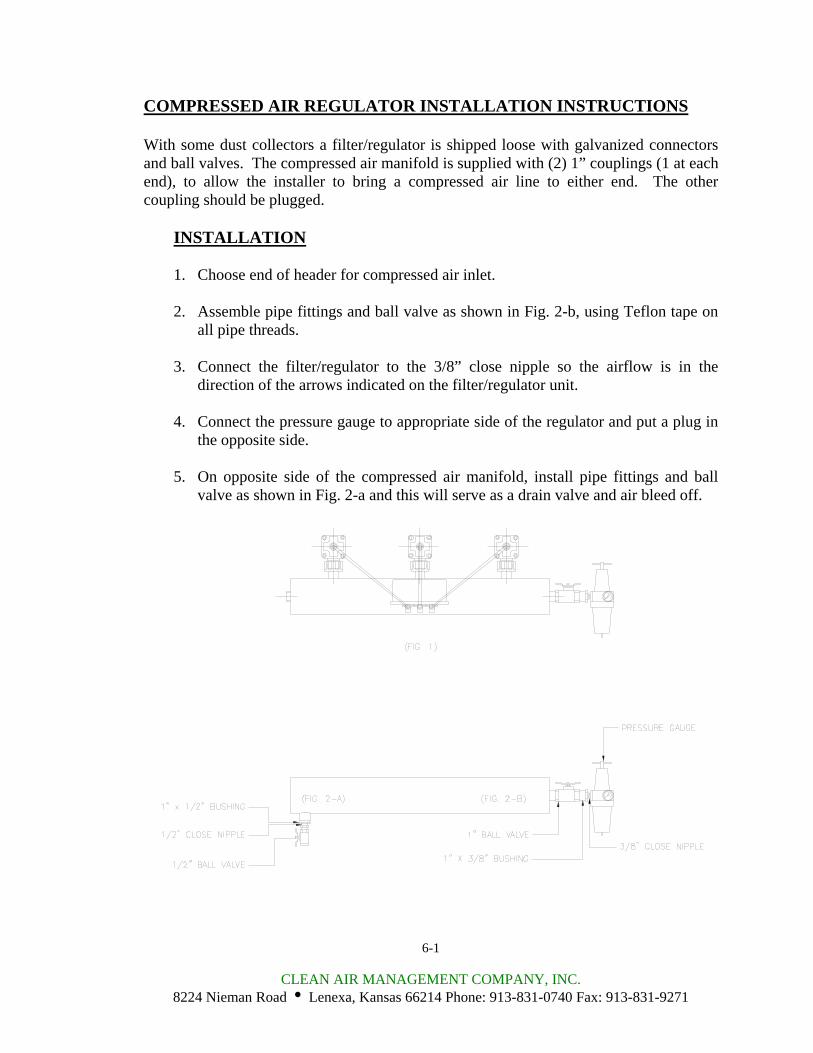
COMPRESSED AIR REGULATOR INSTALLATION INSTRUCTIONS With some dust collectors a filter/regulator is shipped loose with galvanized connectors and ball valves. The compressed air manifold is supplied with (2) 1” couplings (1 at each end), to allow the installer to bring a compressed air line to either end. The other coupling should be plugged.
INSTALLATION
1. Choose end of header for compressed air inlet.
2. Assemble pipe fittings and ball valve as shown in Fig. 2-b, using Teflon tape on all pipe threads.
3. Connect the filter/regulator to the 3/8” close nipple so the airflow is in the
direction of the arrows indicated on the filter/regulator unit.
4. Connect the pressure gauge to appropriate side of the regulator and put a plug in the opposite side.
5. On opposite side of the compressed air manifold, install pipe fittings and ball
valve as shown in Fig. 2-a and this will serve as a drain valve and air bleed off.
6-1
CLEAN AIR MANAGEMENT COMPANY, INC. 8224 Nieman Road i Lenexa, Kansas 66214 Phone: 913-831-0740 Fax: 913-831-9271
START-UP CHECKLIST
1. Installation
Make sure the unit is secured to the floor or mounting surface. The ladder(s) and platform(s) must be tightened and set up according to OSHA requirements. Ducting and piping must be secured and routed out of the way of traffic whenever possible to avoid injury. Ducting must also be free of all debris including moisture.
2. Interior of the dirty air plenum
A. In bottom bag removal collector, inspect the filter bag assemblies referring to
the “Bag and Cage Installation” section of this manual. Improperly installed bags may allow dusty air to enter the clean air plenum and will shorten bag life.
B. Make sure that the filter bag assemblies hang straight and the bottoms do not
touch each other or any part of the collector interior. If this occurs, the bags will develop holes in them wherever they contact and will require replacement.
C. High-level alarms should be connected sufficiently below the air inlet(s) to
avoid a plugged up inlet or blinded off filter bags.
3. Interior of clean air plenum
A. The blowholes in the blowpipes must be centered over the bags.
B. On top bag removal collectors, check to see that bags and cages are properly installed.
C. On top bag removal collectors, the bulkhead fittings must be check for proper
tightness and that the blowpipes are secured.
4. Exterior of dust collector
A. Access doors, inspection ports and spring-loaded relief vents should seat effectively to prevent leakage.
7-1
CLEAN AIR MANAGEMENT COMPANY, INC. 8224 Nieman Road i Lenexa, Kansas 66214 Phone: 913-831-0740 Fax: 913-831-9271
START-UP CHECKLIST (continued)
B. All bolts must be properly tightened.
C. Operate any equipment connected to the dust discharge of the dust collector. Check the rotation of any motor driven equipment such as rotary airlocks, horizontal unloading valves, live bottom bin activators and screw conveyors. Check slide gates and butterfly valves for binding.
5. Explosion relief panels – shear bolt style (when used)
Inspect explosion relief vents (when used) for broken or damaged explosion bolts. MAKE SURE THERE ARE NO STEEL BOLTS USED FOR THE INSTALLATION OF THE EXPLOSION RELIEF PANEL!!! These bolts are made of special high tech poly-vinyl chloride and are designed to relieve at a specific pressure. A magnet should be used to check for steel bolts.
6. Compressed air system
A. The pulse timer board must be correctly wired and mounted in its enclosure
in a suitable location.
B. All the ¼” copper or nylon tubing connections between the diaphragm and the solenoid valves must be tight and the tubing must not be crimped.
C. The plugs (when used) must be removed from the exhaust ports of the
solenoid valves and the tubing from the diaphragm valves must be connected to the “IN” port on the solenoid valves.
D. The compressed air supply system must be equipped to supply clean, dry air
to the pulsing air system. At this time, make sure that there is a suitable air pressure gauge on the air header for reading 0-160 psig.
E. Start the compressed air supply system and check for air leaks in all parts of
the system. If air is heard escaping through one or more of the blowpipes (with the timer off), please refer to the “Troubleshooting the Compressed Air System” section of this manual. Gauge pressure at the compressed air manifold(s) should be 90-100 psig.
7-2
CLEAN AIR MANAGEMENT COMPANY, INC. 8224 Nieman Road i Lenexa, Kansas 66214 Phone: 913-831-0740 Fax: 913-831-9271
START-UP CHECKLIST (continued)
F. With the compressed air system operating, energize the timer to begin pulsing. Check to see that all solenoids are firing by placing a finger over the exhaust port of the solenoid valve. When the solenoid valve being checked is triggered by an electrical pulse from the timer, the finger at the exhaust port should feel a short blast of air. Quickly move to the next solenoid valve in the firing order, noting any valves that do not fire or are stuck open, causing a continuous airflow out of the exhaust port of the valve. At this time, note the quality of the compressed air. It should be clean, dry, and oil free.
G. Allow the compressed air system to operate as long as possible to clear the
system of dirt, rust, scale, welding slag and metal chips that can cause the diaphragm valves to stick.
H. The pressure at the compressed air manifold must recover to 90-100 psig
before each pulse. Make sure that there is adequate compressed air delivery for full pressure recovery when all other systems connected to the same air supply are operating at full capacity.
7-3
CLEAN AIR MANAGEMENT COMPANY, INC. 8224 Nieman Road i Lenexa, Kansas 66214 Phone: 913-831-0740 Fax: 913-831-9271
START-UP DUST CONTROL SYSTEMS
1. Fan or blower system
A. Start the fan or blower and check for proper rotation.
B. Check dust pickup points for proper suction; balance airflow in individual ducts.
C. Check for air leakage at all flanged connections.
2. Equipment start-up sequence
A. The compressed air supply system must be started first.
B. When the pressure gauge on the compressed air manifold indicates that the
system is at full pressure (90-100psig), the pulse timer can be energized.
C. Dust take away equipment such as rotary airlocks, screw conveyors, horizontal unloading valves, live bottom bin activators and pneumatic conveying systems can now be started in their correct sequence.
D. Check that all access doors, hatches, ports, and other openings are closed and
latched or bolted.
E. The main exhaust fan can now be started and brought up to speed.
F. Start the dust laden air through the collector. The collector should be started under partial load to allow the bags to become slowly and evenly coated with dust particles.
On pneumatic conveying systems, watch the differential pressure gauge closely for the first hour or so. If unstable, the collector discharge system may be too small for the volume it is seeing. A quick fix is to reduce the material feed until the discharge rate can be increased.
8-1
CLEAN AIR MANAGEMENT COMPANY, INC. 8224 Nieman Road i Lenexa, Kansas 66214 Phone: 913-831-0740 Fax: 913-831-9271
START-UP DUST CONTROL SYSTEMS (continued)
G. Observe the manometer or magnahelic differential pressure gauge reading. As the new filter bags become coated with dust, the efficiency of the filtering action increases and the differential pressure across the filter bags will also increase. Slowly bring the collector to full load and note the final pressure drop across the filter bags. Never allow the pressure drop across the filter bags to exceed 17” w.g. maximum or the filter bags may collapse.
Note: If the pressure drop continues to increase over 5” w.g. and does not
stabilize, decrease the timer “off time” to fifteen seconds. Should adjustment of the timer “off time” fail to cause the pressure drop to stabilize below 5” w.g., shut down the collector and refer to “Troubleshooting the Collector” or call your CAMCORP representative.
H. When the collector has stabilized, the timer “off time” interval may be slowly
increased for the most economical use of compressed air. As the “off time” is increased, the differential pressure will also increase. Readings up to 6” w.g. are acceptable; however, we recommend operating at 3”-4” w.g. for maximum filter bag life. The timer “off time” may be decreased when lower differential pressure readings are desired. When adjusting the “off time” interval, proceed in small steps allowing the differential pressure to stabilize for several hours between increments.
I. Check the main airflow with a pitot tube, or equivalent measuring device, to
establish initial conditions. If the main airflow must be adjusted up or down to suit the process, repeat step 2-H above.
8-2
CLEAN AIR MANAGEMENT COMPANY, INC. 8224 Nieman Road i Lenexa, Kansas 66214 Phone: 913-831-0740 Fax: 913-831-9271
SHUT-DOWN PROCEDURES
1. Dust control systems
Reverse start-up procedure, shut down fan, then after 5 or 10-minute delay, shut down the timer and discharge system.
2. Pneumatic systems
Reverse start-up procedure, shut down fan, then after 5 or 10 minute delay, shut down the timer and discharge system.
9-1
CLEAN AIR MANAGEMENT COMPANY, INC. 8224 Nieman Road i Lenexa, Kansas 66214 Phone: 913-831-0740 Fax: 913-831-9271
TROUBLESHOOTING THE DUST COLLECTOR
I. Excessive pressure drop across filter bags
The differential pressure gauge or manometer on your dust collector should read 6” w.g. or less. Higher readings and/or steadily increasing readings are an indication that the main airflow through the dust collector may be restricted and a potential process problem such as poor suction at duct pickup points may exist. In extreme cases (over 17” w.g.) filter bags will be damaged. Check the following:
A. Pressure Gauge
Check the differential pressure gauge or manometer and the tubing leading to the dust collector for proper operation. Disconnect the lines at the gauge or manometer and clear with compressed air. Look for loose fittings, cracked, broken or pinched tubing. Make sure that the gauge is zeroed or that the manometer is level, zeroed and contains the correct fluid.
B. Compressed Air System
Inspect the compressed air system as follows to make sure that all of the filter bags are being cleaned:
1. If none of the solenoid valves are operating, check the timer using the
“Troubleshooting the Timer” section.
2. Check the air pressure at the compressed air manifold. It should recover to 90-100 psig before each pulse. If not, check to make sure that the compressed air supply system is in good operating condition, correctly sized and supply lines are not too small or restricted. Listen for the sound of compressed air flowing continuously through one or more rows of filter bags, an indication of a valve or valves “stuck” in the pulsing position. The usual causes for this condition are either a leak in the tubing between the solenoid and diaphragm valves or dirt in the solenoid and/or diaphragm valves.
3. Check to see that all solenoid valves are firing by holding a finger over
each solenoid exhaust port as described in item 6A-6H in the “Start up checklist” section.
10-1
CLEAN AIR MANAGEMENT COMPANY, INC. 8224 Nieman Road i Lenexa, Kansas 66214 Phone: 913-831-0740 Fax: 913-831-9271
TROUBLESHOOTING THE DUST COLLECTOR (continued)
C. Bags Loaded with Dust
A condition known as blinding. If the dust is dry, see paragraph 1-4; if the dust is wet, see paragraphs 5 and 6.
1. Dust Not Discharging from the Hopper
Check hopper for over-loading or bridging across the dust discharge. Correct by repairing dust discharge equipment, replacing with higher capacity equipment, installing hopper vibrators, etc. as required to keep the hopper empty.
2. Air Flow too High
If the main airflow is too high to allow dust to drop off of the filter bags, an excessive pressure drop across the dust collector will result and dust will build up in the system. In many cases this high pressure drop in turn leads to a reduction in the main air flow so that it is necessary to remove the dust accumulation from the filter bags (and the rest of the system) before measuring the main air flow volume.
Visually inspect the bags for heavy caking; if caking is evident, see the note below and take the necessary action to clean the bags. Next, measure the main airflow with a pitot tube or equivalent device and compare with the original volume for which the unit was designed. If the flow is too high, cut back the main fan to prevent a recurrence of the problem.
3. Particle Size and Dust Load
If possible, compare the dust particle size and loading with the original design specifications. Finer dust may cause a higher pressure drop. Do not hesitate to call CAMCORP; we have experience with many kinds of dust.
4. Bags Too Tight
Bags that have shrunk on their cages may not flex sufficiently during the compressed air pulse to loosen caked dust. If the bags were cleaned or laundered, pull a bag tight around its cage; you should be able to “gather” a small fold of material between your fingers.
10-2
CLEAN AIR MANAGEMENT COMPANY, INC. 8224 Nieman Road i Lenexa, Kansas 66214 Phone: 913-831-0740 Fax: 913-831-9271
TROUBLESHOOTING THE DUST COLLECTOR (continued)
5. Water Leaks
Inspect the dust collector housing and ductwork for holes, cracks or loose gasketing where water could enter the collector.
6. Condensation
If moisture has been condensing inside the collector, check the dew point temperature of the incoming air stream. It may be necessary to insulate the collector and/or the ductwork leading to the collector to keep surface temperatures above the dew point and prevent condensation on the filter bags.
NOTE: Collectors that have had blinded or bags caked can possibly be put into service by running the pulsing air system for 15 to 30 minutes with a 10 second “off time” and without the main fan or blower running. If the pressure drop is not lower when the main fan is started again, remove the filter bags from the collector and remove the caked dust by special dry-cleaning. Make sure the timer “off time” has been reset to specifications prior to re-start. Information pertaining to filter bag cleaning may be obtained by calling your CAMCORP sales representative.
II. Extremely Low Pressure Drop
A. Differential Pressure Gauge
Check the differential pressure gauge or manometer and the tubing leading to the dust collector as in I-A of this section.
B. Holes in Filter Bags or Bags Incorrectly Installed.
Inspect the filter bags for holes, rips, tears or excessive wear. Make sure that the filter bags were installed correctly according to the “Bag & Cage Installation” section.
C. Ductwork and Dampers
Inspect the ductwork to and from the dust collector for air leaks or blockage. Make sure that any dampers in the system are correctly positioned to allow for proper air flow through the dust collector.
10-3
CLEAN AIR MANAGEMENT COMPANY, INC. 8224 Nieman Road i Lenexa, Kansas 66214 Phone: 913-831-0740 Fax: 913-831-9271
TROUBLESHOOTING THE DUST COLLECTOR (continued)
D. Leaks in the Housing
Check the tube sheet (flat steel sheets from which the filter bags are suspended) and the dust collector housing for holes, cracks or loose gasketing that would permit air to bypass the dust collector or filter bags.
III. Continuous Flow of Dust in the Clean Air Exhaust (Primary Dusting)
A. Holes in the filter bags or bags incorrectly installed
Inspect the filter bags as in II-B this section.
B. Holes in the tube sheets
Check the tube sheet for holes, cracks or loose bolts that would permit dusty air to bypass the filter bags.
IV. Puff of dust in the clean air exhaust after each pulse (secondary dusting)
A. Compressed air manifold pressure too high
Check compressed air manifold pressure gauge. If the pulsing air pressure is over 100 psig the filter bags may flex excessively and allow fine dust to pass through the bag material.
B. Worn filter bags
Inspect the filter bags for wear. Thin worn bags may not stop fine dust when flexed by a compressed air pulse.
C. Residual dust
If dust has gotten into the clean air plenum because of a dropped filter bag, torn filter bag or a hole in tube sheet, etc., the pulsing air may stir up the dust and allow it to escape into the clean air exhaust after each pulse. Residual dust may also be driven down inside the filter bags by the pulsing air. If the filter bags are filled with several inches of dust, clean both the clean air plenum and the filter bags to avoid further problems.
10-4
CLEAN AIR MANAGEMENT COMPANY, INC. 8224 Nieman Road i Lenexa, Kansas 66214 Phone: 913-831-0740 Fax: 913-831-9271
TROUBLESHOOTING THE DUST COLLECTOR (continued)
V. Short Filter Bag Life
This is often a complicated problem to diagnose and we recommend calling the factory for advice. The following list may be helpful in performing some preliminary checks:
A. Temperature
Operating Temperature above the recommended limit of the filter bag material.
B. Chemical attack
Bag material degrades due to attack from certain chemicals in the dust or gasses in the air stream.
C. High moisture
High moisture content in the collector may cause certain filter bag material to shrink, degrade (more rapidly at elevated temperatures) or blind off.
D. Localized abrasion
Abrasion of the bags at the dusty air inlet; a dust impingement baffle may be required.
E. Filter bag cages failure
Corroded, rusted or broken filter bag cages can cause excessive bag wear. Stainless steel or coated cages are available.
10-5
CLEAN AIR MANAGEMENT COMPANY, INC. 8224 Nieman Road i Lenexa, Kansas 66214 Phone: 913-831-0740 Fax: 913-831-9271
TROUBLESHOOTING THE TIMER
1. Check for mechanical damage.
2. If the “Power On” indicator is not on, check for 120 VAC power input. The “hot” line connection must be connected to terminal “L1”, as this is the fused terminal.
3. Check for a blown fuse; if replacement is necessary, use only 2 AMP standard
3AG fuse (1-1/4” long). Do not use a slow-blow type fuse.
4. Check the wiring from the timer to the solenoids for open or short circuits.
5. After performing steps 1-4, if the timer is still not functioning properly (no output voltage, sequencing problems, etc.) please contact your CAMCORP representative.
11-1
CLEAN AIR MANAGEMENT COMPANY, INC. 8224 Nieman Road i Lenexa, Kansas 66214 Phone: 913-831-0740 Fax: 913-831-9271
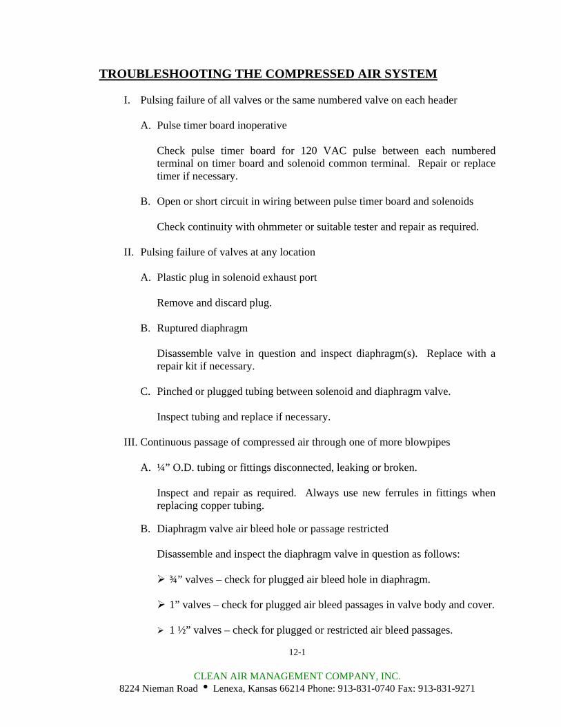
TROUBLESHOOTING THE COMPRESSED AIR SYSTEM
I. Pulsing failure of all valves or the same numbered valve on each header
A. Pulse timer board inoperative
Check pulse timer board for 120 VAC pulse between each numbered terminal on timer board and solenoid common terminal. Repair or replace timer if necessary.
B. Open or short circuit in wiring between pulse timer board and solenoids
Check continuity with ohmmeter or suitable tester and repair as required.
II. Pulsing failure of valves at any location
A. Plastic plug in solenoid exhaust port
Remove and discard plug.
B. Ruptured diaphragm
Disassemble valve in question and inspect diaphragm(s). Replace with a repair kit if necessary.
C. Pinched or plugged tubing between solenoid and diaphragm valve.
Inspect tubing and replace if necessary.
III. Continuous passage of compressed air through one of more blowpipes
A. ¼” O.D. tubing or fittings disconnected, leaking or broken.
Inspect and repair as required. Always use new ferrules in fittings when replacing copper tubing.
B. Diaphragm valve air bleed hole or passage restricted
Disassemble and inspect the diaphragm valve in question as follows:
¾” valves – check for plugged air bleed hole in diaphragm.
1” valves – check for plugged air bleed passages in valve body and cover.
1 ½” valves – check for plugged or restricted air bleed passages.
12-1
CLEAN AIR MANAGEMENT COMPANY, INC. 8224 Nieman Road i Lenexa, Kansas 66214 Phone: 913-831-0740 Fax: 913-831-9271
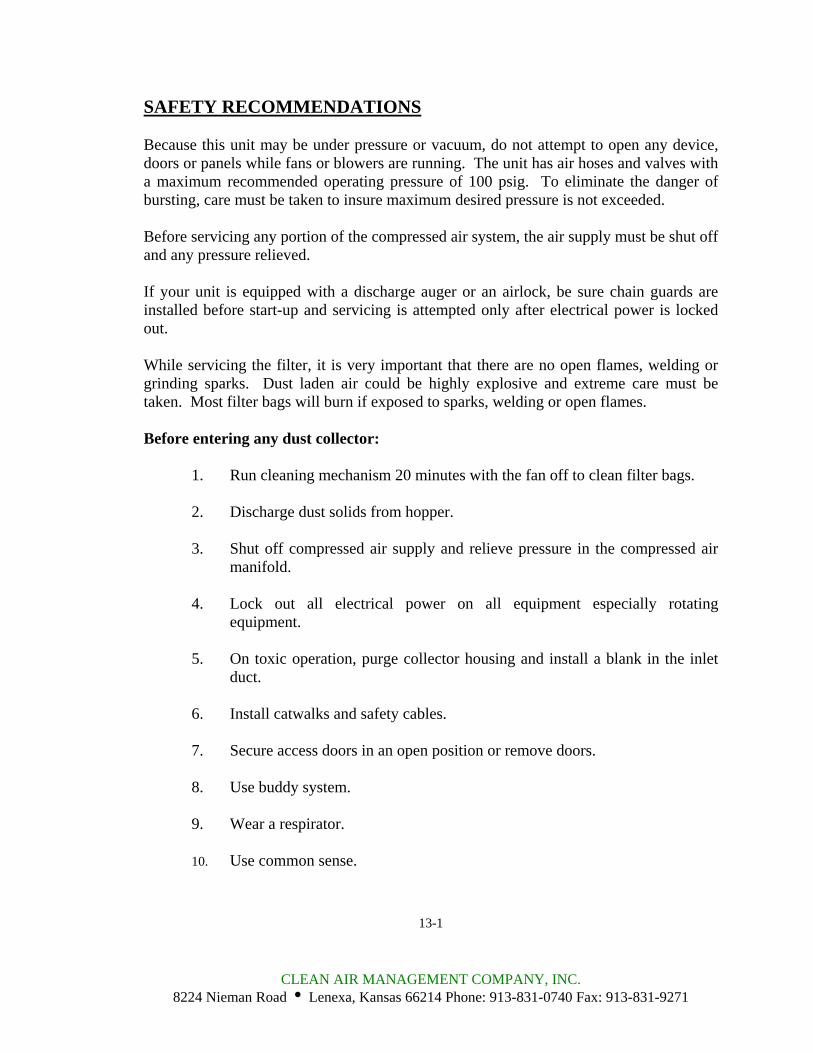
SAFETY RECOMMENDATIONS Because this unit may be under pressure or vacuum, do not attempt to open any device, doors or panels while fans or blowers are running. The unit has air hoses and valves with a maximum recommended operating pressure of 100 psig. To eliminate the danger of bursting, care must be taken to insure maximum desired pressure is not exceeded. Before servicing any portion of the compressed air system, the air supply must be shut off and any pressure relieved. If your unit is equipped with a discharge auger or an airlock, be sure chain guards are installed before start-up and servicing is attempted only after electrical power is locked out. While servicing the filter, it is very important that there are no open flames, welding or grinding sparks. Dust laden air could be highly explosive and extreme care must be taken. Most filter bags will burn if exposed to sparks, welding or open flames. Before entering any dust collector:
1. Run cleaning mechanism 20 minutes with the fan off to clean filter bags. 2. Discharge dust solids from hopper.
3. Shut off compressed air supply and relieve pressure in the compressed air
manifold.
4. Lock out all electrical power on all equipment especially rotating equipment.
5. On toxic operation, purge collector housing and install a blank in the inlet
duct.
6. Install catwalks and safety cables.
7. Secure access doors in an open position or remove doors.
8. Use buddy system.
9. Wear a respirator.
10. Use common sense.
13-1
CLEAN AIR MANAGEMENT COMPANY, INC. 8224 Nieman Road i Lenexa, Kansas 66214 Phone: 913-831-0740 Fax: 913-831-9271
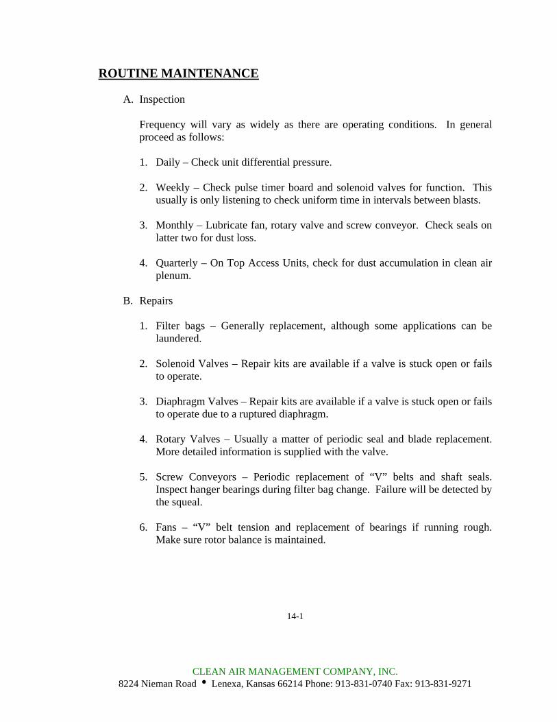
ROUTINE MAINTENANCE
A. Inspection
Frequency will vary as widely as there are operating conditions. In general proceed as follows:
1. Daily – Check unit differential pressure.
2. Weekly – Check pulse timer board and solenoid valves for function. This
usually is only listening to check uniform time in intervals between blasts.
3. Monthly – Lubricate fan, rotary valve and screw conveyor. Check seals on latter two for dust loss.
4. Quarterly – On Top Access Units, check for dust accumulation in clean air
plenum.
B. Repairs
1. Filter bags – Generally replacement, although some applications can be laundered.
2. Solenoid Valves – Repair kits are available if a valve is stuck open or fails
to operate.
3. Diaphragm Valves – Repair kits are available if a valve is stuck open or fails to operate due to a ruptured diaphragm.
4. Rotary Valves – Usually a matter of periodic seal and blade replacement.
More detailed information is supplied with the valve.
5. Screw Conveyors – Periodic replacement of “V” belts and shaft seals. Inspect hanger bearings during filter bag change. Failure will be detected by the squeal.
6. Fans – “V” belt tension and replacement of bearings if running rough.
Make sure rotor balance is maintained.
14-1
CLEAN AIR MANAGEMENT COMPANY, INC. 8224 Nieman Road i Lenexa, Kansas 66214 Phone: 913-831-0740 Fax: 913-831-9271