Duplex Stainless Steels Welding Guidelines · 2020-01-14 · and FCAW); a good accessibility for...
56
Duplex Stainless Steels Welding Guidelines
Transcript of Duplex Stainless Steels Welding Guidelines · 2020-01-14 · and FCAW); a good accessibility for...

Duplex Stainless SteelsWelding Guidelines
Duplex Stainless Steels Welding Guidelines
Industeel
Note: The disclosed information remains Industeel France s.a. property
and cannot be disclosed to third parties without his prior written approval.
Although every care has been taken to provide our best recommendations,
based upon the indications sent to us, our experience and present knowledge,
Industeel France s.a. cannot guarantee that these recommendations are
appropriate or economical. Any recommendation is given for information
purpose only without any acknowledgement of any responsibility from
Industeel France s.a or any ArcelorMittal subsidiary. Industeel France s.a. or
Le Creusot Research Center - ArcelorMittal Global R&D will not liable for any
direct or indirect damages, incidental or consequential loss related to the
applications of information and advices given in this document.
Publisher: Industeel ArcelorMittal - 56 rue Clémenceau - 71201 LE CREUSOT
Writer: Corrosion Resistant Alloys R&D Department
Layout: Industeel Marketing Department
Printing: SEIC Imprimerie - 71200 LE CREUSOT
English Edition June 2019
© Industeel ArcelorMittal

Lexicon
F% Ferrite Percentage
FCAW Flux Cored Arc Welding
FN Ferrite Number
GMAW Gas Metal Arc Welding
GTAW Gas Tungsten Arc Welding
HAZ Heat Affected Zone
HI Heat Input
I Intensity
PAW Plasma Arc Welding
PGMAW Pulsed Gas Metal Arc Welding
PRENPitting Resistance Equivalent
Number
PWHT Post Welding Heat Treatment
pWPSpreliminary Welding Procedure
Specification
SAW Submerged Arc Welding
SMAW Shielded Metal Arc Welding
TTTTime Temperature
Transformation
U Voltage
UT Utrasonic Testing
Vr Cooling Speed
WRC Welding Research Council
Ws Welding Speed

Overview of duplex welding
2.1 Welding metallurgy 22
2.2 Welded joints preparation 26
2.3 Thermal welding conditions 28
2.4 Welding processes 29
2.5 Ferrite determination 34
2.6 Post-fabrication clean up 36
2.7 Inspection 38
An introduction to duplex stainless steels
General points 12
1.1 Chemical compositions 14
1.2 Mechanical properties 16
1.3 Corrosion resistance 18
1.4 Main applications 20

Properties prediction software
4. Properties prediction software 104
Welding datasheets
3.1 UR™ 2202 42
3.2 UR™ 2304 52
3.3 UR™ 2205 60
3.4 UR™ 2205Mo 70
3.5 UR™ 2507 78
3.6 UR™ 2507Cu 88
3.7 UR™ 2507W 96

Introduction
12 13
General points
Duplex stainless steels were introduced and have been actively developed by European companies since 1935. Their features make them very attractive compared to equivalent austenitic grades: higher resistance to Stress Corrosion Cracking, higher mechanical properties and lower alloy cost.
They present excellent cost/properties ratios particularly in critical applications including: oil and gas, chemical industry, pulp and paper industry, water systems, desalination plants, pollution control equipment, chemical tankers, ...
Consideration of sustainability and Life Cycle Cost are moving other applications to Duplex use (architecture and construction, storage tanks) ensuring without any doubt further development for the whole duplex family.
In view of the continuous improvement of their properties and their growing availability, Duplex stainless steels will remain an attractive solution to the future needs of designers and users in mechanical engineering.
General points
Introduction
14 15
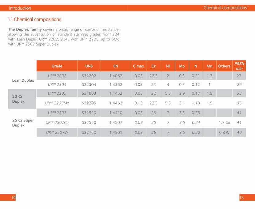
The Duplex family covers a broad range of corrosion resistance, allowing the substitution of standard stainless grades from 304 with Lean Duplex UR™ 2202, 904L with UR™ 2205, up to 6Mo with UR™ 2507 Super Duplex.
1.1 Chemical compositions
Chemical compositions
Grade UNS EN C max Cr Ni Mo N Mn OthersPRENmin
Lean DuplexUR™ 2202 S32202 1.4062 0.03 22.5 2 0.3 0.21 1.3 27
UR™ 2304 S32304 1.4362 0.03 23 4 0.3 0.12 1 26
22 Cr Duplex
UR™ 2205 S31803 1.4462 0.03 22 5.3 2.9 0.17 1.9 33
UR™ 2205Mo S32205 1.4462 0.03 22.5 5.5 3.1 0.18 1.9 35
25 Cr Super Duplex
UR™ 2507 S32520 1.4410 0.03 25 7 3.5 0.26 41
UR™ 2507Cu S32550 1.4507 0.03 25 7 3.5 0.24 1.7 Cu 41
UR™ 2507W S32760 1.4501 0.03 25 7 3.5 0.22 0.8 W 40

Introduction
16 17
1.2 Mechanical properties
The mechanical properties of Duplex are higher than the equivalent austenitic grades, their yield strength is about the double of those of classical grades.
For detailed mechanical properties consult datasheets: https://industeel.arcelormittal.com/products/stainless-steels/austenitic-ferritic-duplex/
Mechanical properties
Grade UNS EN
0.2 Y.S - Rp 0.2 min
ASTM/EN
0.2 Y.S - Rp 0.2
typical value
UTS - Rmmin ASTM/EN
UTS - Rm typical value
El - A
MPa ksi MPa ksi MPa ksi MPa ksi %
Lean DuplexUR™ 2202 S32202 1.4062 450 65 520 75 650 94 710 103 30
UR™ 2304 S32304 1.4362 400 58 480 70 630 91 670 97 25
22 Cr DuplexUR™ 2205 S31803 1.4462 460 67 530 77 655 95 750 109 25
UR™ 2205Mo S32205 1.4462 460 67 535 78 655 95 750 109 25
25 Cr Super Duplex
UR™ 2507 S32520 1.4410 550 80 620 90 795 115 820 119 25
UR™ 2507CuS32520S32550
1.4507 550 80 630 91 750 109 795 115 25
UR™ 2507W S32760 1.4501 550 80 625 91 750 109 790 115 25
Introduction
18 19
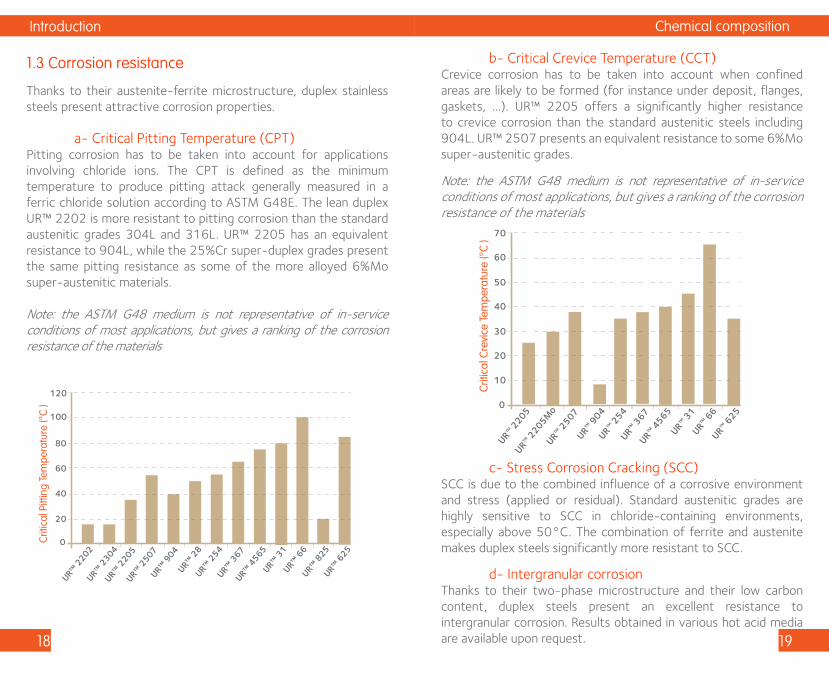
1.3 Corrosion resistance
Thanks to their austenite-ferrite microstructure, duplex stainless steels present attractive corrosion properties.
a- Critical Pitting Temperature (CPT)Pitting corrosion has to be taken into account for applications involving chloride ions. The CPT is defined as the minimum temperature to produce pitting attack generally measured in a ferric chloride solution according to ASTM G48E. The lean duplex UR™ 2202 is more resistant to pitting corrosion than the standard austenitic grades 304L and 316L. UR™ 2205 has an equivalent resistance to 904L, while the 25%Cr super-duplex grades present the same pitting resistance as some of the more alloyed 6%Mo super-austenitic materials.
Note: the ASTM G48 medium is not representative of in-service conditions of most applications, but gives a ranking of the corrosion resistance of the materials
Criti
cal P
ittin
g Te
mpe
ratu
re (°
C )
0
20
40
60
80
120
100
UR™ 2
205
UR™ 2
202
UR™ 2
507UR™
904
UR™ 2
8UR™
254
UR™ 3
67
UR™ 3
1UR™
66
UR™ 2
304
UR™ 8
25UR™
625
UR™ 4
565
Lorem ipsum
Chemical composition
b- Critical Crevice Temperature (CCT)Crevice corrosion has to be taken into account when confined areas are likely to be formed (for instance under deposit, flanges, gaskets, …). UR™ 2205 offers a significantly higher resistance to crevice corrosion than the standard austenitic steels including 904L. UR™ 2507 presents an equivalent resistance to some 6%Mo super-austenitic grades.
Note: the ASTM G48 medium is not representative of in-service conditions of most applications, but gives a ranking of the corrosion resistance of the materials
c- Stress Corrosion Cracking (SCC)SCC is due to the combined influence of a corrosive environment and stress (applied or residual). Standard austenitic grades are highly sensitive to SCC in chloride-containing environments, especially above 50°C. The combination of ferrite and austenite makes duplex steels significantly more resistant to SCC.
d- Intergranular corrosionThanks to their two-phase microstructure and their low carbon content, duplex steels present an excellent resistance to intergranular corrosion. Results obtained in various hot acid media are available upon request.
Criti
cal C
revi
ce Te
mpe
ratu
re (°
C )
0
10
20
30
40
60
70
50
UR™ 2507
UR™ 2205
UR™ 904
UR™ 254
UR™ 367
UR™ 4565
UR™ 31
UR™ 66
UR™ 625
UR™ 2205M
o

Introduction
20 21
1.4 Main applications
Duplex stainless steels are commonly used for pipes, tanks and pressure vessel equipment in various markets and applications: • Oil & Gas industry • Pulp & Paper industry • Water / Seawater industry • Architecture, building and construction • Food industry • Pollution control • Chemical industry
Main applications
Overview of duplex welding
22 23
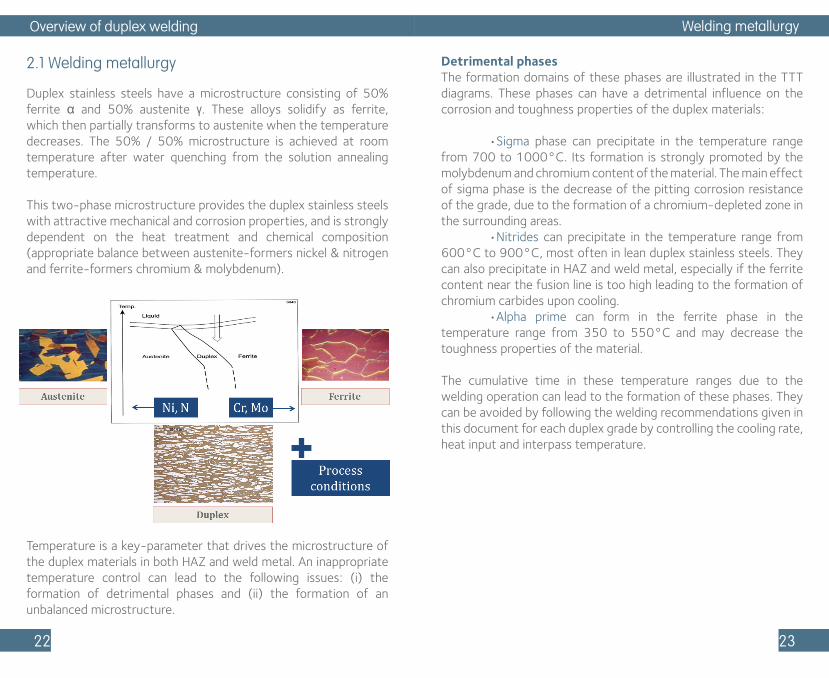
2.1 Welding metallurgy
Duplex stainless steels have a microstructure consisting of 50% ferrite α and 50% austenite γ. These alloys solidify as ferrite, which then partially transforms to austenite when the temperature decreases. The 50% / 50% microstructure is achieved at room temperature after water quenching from the solution annealing temperature.
This two-phase microstructure provides the duplex stainless steels with attractive mechanical and corrosion properties, and is strongly dependent on the heat treatment and chemical composition (appropriate balance between austenite-formers nickel & nitrogen and ferrite-formers chromium & molybdenum).
Temperature is a key-parameter that drives the microstructure of the duplex materials in both HAZ and weld metal. An inappropriate temperature control can lead to the following issues: (i) the formation of detrimental phases and (ii) the formation of an unbalanced microstructure.
Detrimental phases The formation domains of these phases are illustrated in the TTT diagrams. These phases can have a detrimental influence on the corrosion and toughness properties of the duplex materials:
•Sigma phase can precipitate in the temperature range from 700 to 1000°C. Its formation is strongly promoted by the molybdenum and chromium content of the material. The main effect of sigma phase is the decrease of the pitting corrosion resistance of the grade, due to the formation of a chromium-depleted zone in the surrounding areas. •Nitrides can precipitate in the temperature range from 600°C to 900°C, most often in lean duplex stainless steels. They can also precipitate in HAZ and weld metal, especially if the ferrite content near the fusion line is too high leading to the formation of chromium carbides upon cooling. •Alpha prime can form in the ferrite phase in the temperature range from 350 to 550°C and may decrease the toughness properties of the material.
The cumulative time in these temperature ranges due to the welding operation can lead to the formation of these phases. They can be avoided by following the welding recommendations given in this document for each duplex grade by controlling the cooling rate, heat input and interpass temperature.
Welding metallurgy
Overview of duplex welding
24 25
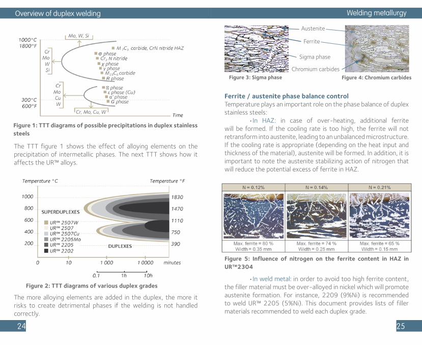
Figure 1: TTT diagrams of possible precipitations in duplex stainless steels
The TTT figure 1 shows the effect of alloying elements on the precipitation of intermetallic phases. The next TTT shows how it affects the UR™ alloys.
Figure 2: TTT diagrams of various duplex grades
The more alloying elements are added in the duplex, the more it risks to create detrimental phases if the welding is not handled correctly.
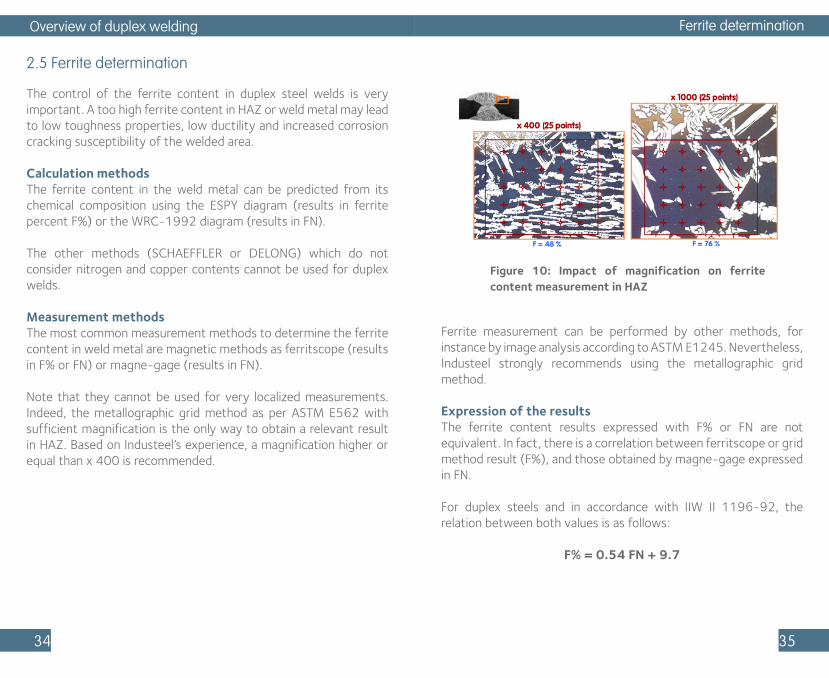
Ferrite / austenite phase balance controlTemperature plays an important role on the phase balance of duplex stainless steels: •In HAZ: in case of over-heating, additional ferrite will be formed. If the cooling rate is too high, the ferrite will not retransform into austenite, leading to an unbalanced microstructure. If the cooling rate is appropriate (depending on the heat input and thickness of the material), austenite will be formed. In addition, it is important to note the austenite stabilizing action of nitrogen that will reduce the potential excess of ferrite in HAZ.
•In weld metal: in order to avoid too high ferrite content, the filler material must be over-alloyed in nickel which will promote austenite formation. For instance, 2209 (9%Ni) is recommended to weld UR™ 2205 (5%Ni). This document provides lists of filler materials recommended to weld each duplex grade.
Figure 5: Influence of nitrogen on the ferrite content in HAZ in UR™2304
Welding metallurgy
Figure 3: Sigma phase Figure 4: Chromium carbides
Austenite
Ferrite
Sigma phase
Chromium carbides

Overview of duplex welding
26 27
2.2 Welded joints preparation
The assembly must be designed in such a manner that the penetration weld is performed without an excessive dilution of the base metal. The groove type must be configured in order to have a good gaseous shielding protection (GTAW, GMAW, PAW, and FCAW); a good accessibility for welding guns in the bottom of the joint is required. Some examples of welded joint preparations are presented in the following tables, which can be used for butt-welding of duplex stainless steels, considering various plate thicknesses.
Grooving can be performed by machining or thermal cutting (oxy-acetylene gas with iron powder or plasma) followed by grinding to eliminate oxide and HAZ.
As for all other stainless steels, the welding zone must be carefully cleaned with a chlorine-free solvent in order to eliminate any grease or paint marks.
Welded joints preparation
Figure 6: Joint design for both sides butt-welding
Figure 7: Joint design for one side butt-welding

Overview of duplex welding
28 29
2.3 Thermal welding conditions
Pre-heatingPreheating of duplex steels is not recommended and can have a detrimental impact on the properties of the welded assembly. To remove moisture, the duplex steel can be heated up to 100°C (210°F).
Interpass temperatureAs a general rule, the interpass temperature should be limited to 150°C (300°F) for lean duplex and duplex steels, and 100°C (210°F) for super-duplex steels. Too high interpass temperatures will decrease the cooling rate. In this case, intermetallic phase, nitrides or carbides precipitation is likely to occur in the weld metal.
Post-heatingPost-heating is not recommended and must be avoided if the temperature exceeds 290°C (550°F).
Welding processes
2.4 Welding processes
All welding processes used on austenitic stainless steels are applicable to duplex stainless steels.
Figure 8: Welding processes for duplex stainless steels
Note that the welding processes without filler metal require a particular attention because of the loss of nitrogen content in molten metal not always compensated by a nitrogen addition in the welding gas. In this case, a solution-annealing post-welding heat treatment allows to reach the optimal microstructure and corrosion resistance of the weld metal.
Welding processes
With filler material Without filler material
Common Welding
Processes
- SMAW- FCAW- SAW- GMAW/pulsed GMAW- GTAW- PAW
- GTAW- PAW
Specific Welding Processs
- Electoslag
- Laser welding- Electron beam welding- GTAW variants- Resistance welding- Friction welding- Stud welding
Nitrogen content in the shielding gas
or PWHT

Overview of duplex welding
30 31
Shielded Metal Arc Welding – SMAWSMAW can be used from a thickness of 5 mm. Rutile, basic-rutile or basic-type covered electrode are available to weld duplex steels. The highest levels of toughness and the highest capacities of deformation are obtained with basic-covered electrodes. These basic electrodes will preferably be used if the weld has to support strong deformations (head forming) or if the weld must have good toughness properties at low temperature.
The recommended heat input must be considered to choose the most appropriate electrode diameter. The weld should be made with stringer beads (the width of weave should not exceed twice the electrode diameter). When a covered electrode is used to make the root pass, a backing shielding gas, as used for GTAW, is recommended. In the opposite case, the penetration must be finely ground.In all cases, the welder must hold a short arc to avoid any atmospheric nitrogen pick-up which may lead to an unacceptable level of porosities, for an already nitrogen-alloyed duplex weld metal.
Submerged Arc Welding – SAWThis welding process is used for flat position with a plate thickness from 10 mm. Basic flux leads to the best toughness properties and best ductility in weld metal, whereas rutile flux gives an easier removal of slag and often a lower sensibility to porosity.
A small filler diameter (often Ø 2,4 mm) must be chosen to respect recommended heat inputs. For a given heat input, the choice of welding parameters I, U, Ws is important. The use of both a moderate current and a low welding speed (Ws < 45 cm/min) strongly reduces the risk of shrinkage voids or porosities which could be unacceptable according to the most often used specifications of compactness (X-Ray exams ASME VIII for instance).
Passes too fitted (backing pass after arc gouging and too narrow grinding) must be avoided. The width of the bead should always be higher than its depth.
Welding processes
Flux Cored Arc Welding – FCAWMineral flux cored wires can be used with GMAW and Ar + CO
2
(18%) shielding gas. The high shielding gas activity and the rutile-type of the cored wires lead to rather low toughness levels but acceptable for applications at room temperature or higher.
Gas Metal Arc Welding and Pulsed Gas Metal Arc Welding – GMAW and PGMAWThese semi-automatic or automatic welding processes are used for thicknesses from 5 mm: •The short-circuiting transfer is used for low heat inputs and therefore for the lowest plate thicknesses; •The spray-arc transfer or axial transfer, which is obtained with high current and voltage, leads to a stable arc and high deposition rates; •The pulsed arc transfer is obtained with special power sources. This process allows to benefit from spray-arc advantages with reduced heat inputs and makes it possible to perform welding in all positions.
The shielding gas composition is very important for duplex welding when using GMAW or pulsed GMAW processes. The shielding gas must avoid both nitrogen losses of weld metal and weld metal oxidation. Some ternary gases (Ar + CO
2 + N
2) or quarterly gases
(Ar + CO2
+ He + N2) are available specifically for these two
processes. When an austenitic filler metal is used, the shielding gas should be Ar + He + CO
2 type.
The quality of the shielding gas must be stable. Leak of water-cooled gun system or pick-up of atmospheric nitrogen must be avoided since lack of compactness, such as porosities in the weld metal, may then be created.
When GMAW is used for the root pass, a backing shielding gas is necessary and will be ensured by pure argon (Ar > 99,95%).

Overview of duplex welding
32 33
Gas Tungsten Arc Welding – GTAWGTAW, manual or automatic, is frequently used to weld duplex steels when the plate thickness is lower than 15 mm, or for penetration passes before filling with SMAW or SAW processes.
The GTAW welding process leads to the purest weld metal (lowest oxygen content compared to other processes) and is the less sensitive to the lack of compactness phenomenon.
When a duplex wire is used, the recommended shielding gas is an Ar (98%) + N
2 (2%) mixture. Additional nitrogen can be added but
can also lead to a deterioration of the tungsten electrode. In this case, the nitrogen addition in the shielding gas is important to keep a satisfactory microstructure and appropriate corrosion resistance even when the selected filler material is a nickel over-alloyed grade. When an austenitic filler metal is used, the shielding gas must be pure argon.
The flow rate must be carefully set according to the nozzle diameter and the use or not of a gas diffuser. Turbulences (too high flow rate) which can introduce atmosphere in the weld pool must be avoided. Moreover, the tungsten electrode extension can never exceed twice or three times its diameter, except when the torch has a gas lens. In this case, an electrode length of about 20 mm can be used to solve the problem of accessibility. If not, uncontrolled nitrogen addition in the weld metal may occur. It may result in a too low ferrite content as well as compactness defects. A backing shielding gas is necessary (pure argon Ar > 99,95%).
Welding must be performed with stringer beads and moderate beads thickness. Too thick passes are indeed more sensitive to porosity (more difficult degassing).
Welding gases with hydrogen addition are not permitted to weld duplex steels due to the risk of embrittlement of the weld metal.
Note on dissimilar weldsDuplex can be easily welded to carbon, low alloy and austenitic stainless steels, with various welding consumables. Duplex, super-duplex and austenitic filler materials can be used. Special attention must be paid to the dilution to avoid the formation of a brittle structure and to limit the risk of hot cracking.
Welding processes
Figure 9: Dissimilar weld
Overview of duplex welding
34 35
2.5 Ferrite determination
The control of the ferrite content in duplex steel welds is very important. A too high ferrite content in HAZ or weld metal may lead to low toughness properties, low ductility and increased corrosion cracking susceptibility of the welded area.
Calculation methodsThe ferrite content in the weld metal can be predicted from its chemical composition using the ESPY diagram (results in ferrite percent F%) or the WRC-1992 diagram (results in FN).
The other methods (SCHAEFFLER or DELONG) which do not consider nitrogen and copper contents cannot be used for duplex welds.
Measurement methodsThe most common measurement methods to determine the ferrite content in weld metal are magnetic methods as ferritscope (results in F% or FN) or magne-gage (results in FN).
Note that they cannot be used for very localized measurements. Indeed, the metallographic grid method as per ASTM E562 with sufficient magnification is the only way to obtain a relevant result in HAZ. Based on Industeel’s experience, a magnification higher or equal than x 400 is recommended.
Ferrite determination
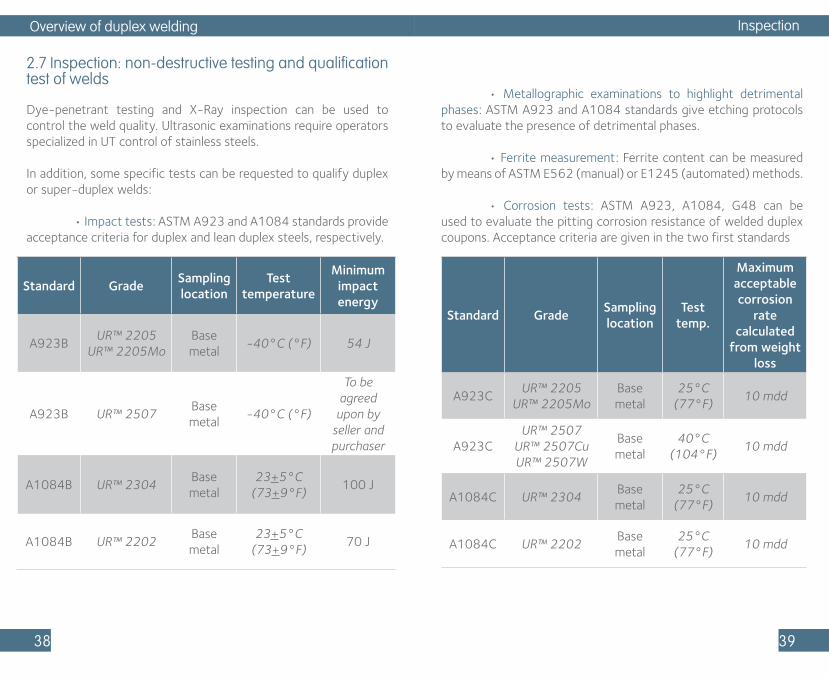
Figure 10: Impact of magnification on ferrite content measurement in HAZ
Ferrite measurement can be performed by other methods, for instance by image analysis according to ASTM E1245. Nevertheless, Industeel strongly recommends using the metallographic grid method. Expression of the resultsThe ferrite content results expressed with F% or FN are not equivalent. In fact, there is a correlation between ferritscope or grid method result (F%), and those obtained by magne-gage expressed in FN.
For duplex steels and in accordance with IIW II 1196-92, the relation between both values is as follows:
F% = 0.54 FN + 9.7

Overview of duplex welding
36 37
Ferrite content recommendationsBased on Industeel’s experience, the following ferrite content ranges can be recommended to obtain the appropriate mechanical and corrosion properties of the welded assembly.
Welding processes Localization Method Ferrite %
SMAW - FCAW - SAW
Weld metalEspy
Ferritscope20 to 35 20 to 40
GMAW - GTAW - PAW
Weld metalEspy
Ferritscope20 to 50 20 to 60
All processes HAZPoint grid at
> x 400< 70
Table 1: Industeel’s recommendations of ferrite content ranges
2.6 Post-fabrication cleanup
Welding operations can induce various surface defects such as weld spatters, arc strikes, heat tints, embedded iron contamination, as well as the presence of paint, dirt and crayon marks. These defects can initiate corrosion on the duplex plate surface and must be removed. That is why post-fabrication cleanup is very important, and shall be the same as for other families of stainless steels.
Mechanical methods such as fine abrasive grinding are commonly used to preliminary remove any contamination of the welded areas caused by the welding operation.
Weld cleanup general rules are the same as for stainless steels.
Embedded ironFerrous contamination can be removed by chemical cleaning with nitric acid. Note that carbon steel tooling must be avoided as much as possible in the shop to decrease the risk of iron contamination.
Organic contamination (paint, oil, crayon marks)These surface defects can be removed with a chlorine-free solvent.
Heat tintsWith exposure to oxygen at high temperature, a thin “straw tinted” chromium oxide layer forms. As a result, a chromium-depleted layer forms beneath the heat tint, and may have a reduced corrosion resistance. Heat tint oxides can be removed by pickling using commercial picking pastes or by means of immersion in a fluo-nitric bath.
Post-fabrication cleanup
Figure 11: Influence of heat tints on the corrosion resistance of a welded UR™ 2205 coupon
Pote
ntia
l (V
/SC
E)
0.8
0.4
0Reference
0.6
0.2
Heat tint Heat tint+grinding
Heat tint +HF/HNO3pickling 15°C/24h
1
1.2
Heat tint +HF/HNO3pickling 55°C/45mn
water oxidation
area
pitting area
Overview of duplex welding
38 39
2.7 Inspection: non-destructive testing and qualification test of welds
Dye-penetrant testing and X-Ray inspection can be used to control the weld quality. Ultrasonic examinations require operators specialized in UT control of stainless steels.
In addition, some specific tests can be requested to qualify duplex or super-duplex welds:
• Impact tests: ASTM A923 and A1084 standards provide acceptance criteria for duplex and lean duplex steels, respectively.
Standard GradeSampling location
Test temperature
Minimum impact energy
A923BUR™ 2205
UR™ 2205MoBase metal
-40°C (°F) 54 J
A923B UR™ 2507Base metal
-40°C (°F)
To be agreed
upon by seller and purchaser
A1084B UR™ 2304Base metal
23+5°C (73+9°F)
100 J
A1084B UR™ 2202Base metal
23+5°C (73+9°F)
70 J
• Metallographic examinations to highlight detrimental phases: ASTM A923 and A1084 standards give etching protocols to evaluate the presence of detrimental phases.
• Ferrite measurement: Ferrite content can be measured by means of ASTM E562 (manual) or E1245 (automated) methods.
• Corrosion tests: ASTM A923, A1084, G48 can be used to evaluate the pitting corrosion resistance of welded duplex coupons. Acceptance criteria are given in the two first standards
Inspection
Standard GradeSampling location
Test temp.
Maximum acceptable corrosion
rate calculated
from weight loss
A923CUR™ 2205
UR™ 2205MoBase metal
25°C (77°F)
10 mdd
A923CUR™ 2507
UR™ 2507Cu UR™ 2507W
Base metal
40°C (104°F)
10 mdd
A1084C UR™ 2304Base metal
25°C (77°F)
10 mdd
A1084C UR™ 2202Base metal
25°C (77°F)
10 mdd

Overview of duplex welding
40 41
Standards references
• ASTM E562, « Standard Test Method for Determining Volume Fraction by Systematic Manual Point Count», 2011.
• ASTM E1245, « Standard Practice for Determining the Inclusion or Second-Phase Constituent Content of Metals by Automatic Image Analysis», 2016.
• ASTM A923, « Standard Test Methods for Detecting Detrimental Intermetallic Phase in Duplex Austenitic/Ferritic Stainless Steels», 2014.
• ASTM A1084, « Standard Test Method for Detecting Detrimental Phases in Lean Duplex Austenitic/Ferritic Stainless Steels», 2015.
• ASME VIII, « BPVC Section VIII-Rules for Construction of Pressure Vessels Division 1», 2015.
• DVS-IIW/EWF 1196 November, 2005.
Bibliography
Bibliography
• « The Welding of Stainless Steel – Materials and Applications Series, Volume 3 » Euro Inox by Pierre-Jean Cunat, 2007 (Second Edition).
• « BM650 – Chaudronnerie en aciers inoxydables » Techniques de l’ingénieur, 2007.
• « Practical Guideline for the Fabrication of Duplex Stainless Steel » IMOA, 2014 (Third Edition).
Bibliography
Welding datasheets
42 43
Standard
3.1 UR™ 2202
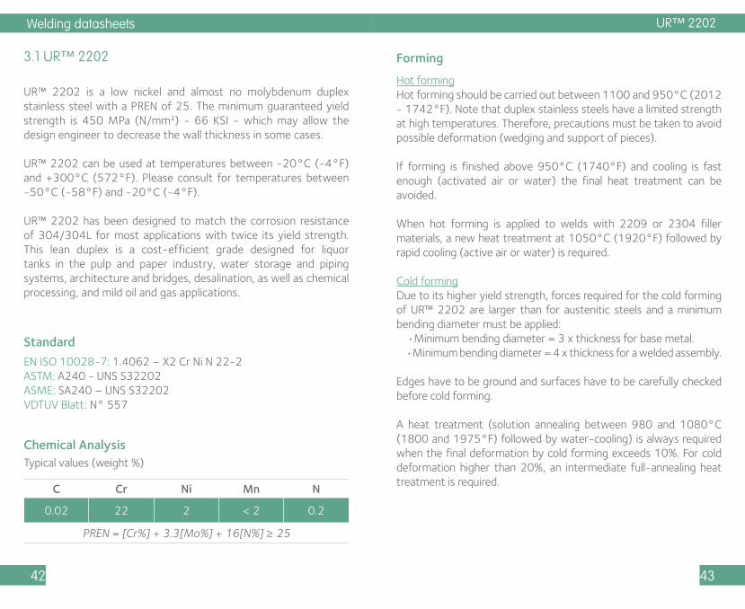
UR™ 2202 is a low nickel and almost no molybdenum duplex stainless steel with a PREN of 25. The minimum guaranteed yield strength is 450 MPa (N/mm²) - 66 KSI - which may allow the design engineer to decrease the wall thickness in some cases.
UR™ 2202 can be used at temperatures between -20°C (-4°F) and +300°C (572°F). Please consult for temperatures between -50°C (-58°F) and -20°C (-4°F).
UR™ 2202 has been designed to match the corrosion resistance of 304/304L for most applications with twice its yield strength. This lean duplex is a cost-efficient grade designed for liquor tanks in the pulp and paper industry, water storage and piping systems, architecture and bridges, desalination, as well as chemical processing, and mild oil and gas applications.
EN ISO 10028-7: 1.4062 – X2 Cr Ni N 22-2ASTM: A240 - UNS S32202ASME: SA240 – UNS S32202VDTUV Blatt: N° 557
C Cr Ni Mn N
0.02 22 2 < 2 0.2
PREN = [Cr%] + 3.3[Mo%] + 16[N%] ≥ 25
Chemical AnalysisTypical values (weight %)
UR™ 2202
Hot formingHot forming should be carried out between 1100 and 950°C (2012 - 1742°F). Note that duplex stainless steels have a limited strength at high temperatures. Therefore, precautions must be taken to avoid possible deformation (wedging and support of pieces).
If forming is finished above 950°C (1740°F) and cooling is fast enough (activated air or water) the final heat treatment can be avoided.
When hot forming is applied to welds with 2209 or 2304 filler materials, a new heat treatment at 1050°C (1920°F) followed by rapid cooling (active air or water) is required.
Cold formingDue to its higher yield strength, forces required for the cold forming of UR™ 2202 are larger than for austenitic steels and a minimum bending diameter must be applied: •Minimum bending diameter = 3 x thickness for base metal. •Minimum bending diameter = 4 x thickness for a welded assembly.
Edges have to be ground and surfaces have to be carefully checked before cold forming.
A heat treatment (solution annealing between 980 and 1080°C (1800 and 1975°F) followed by water-cooling) is always required when the final deformation by cold forming exceeds 10%. For cold deformation higher than 20%, an intermediate full-annealing heat treatment is required.
Forming
Welding datasheets
44 45
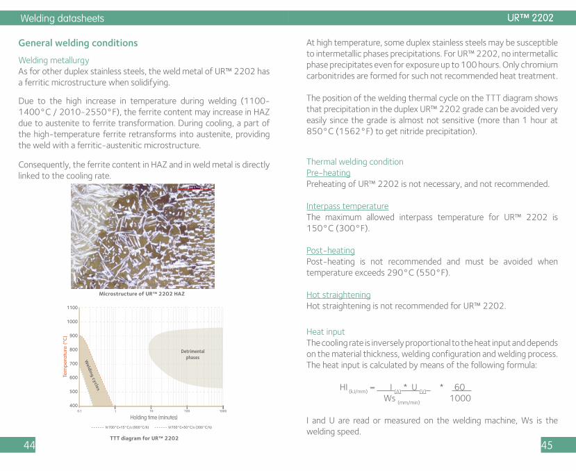
Welding metallurgyAs for other duplex stainless steels, the weld metal of UR™ 2202 has a ferritic microstructure when solidifying.
Due to the high increase in temperature during welding (1100-1400°C / 2010-2550°F), the ferrite content may increase in HAZ due to austenite to ferrite transformation. During cooling, a part of the high-temperature ferrite retransforms into austenite, providing the weld with a ferritic-austenitic microstructure.
Consequently, the ferrite content in HAZ and in weld metal is directly linked to the cooling rate.
General welding conditions
Tem
pe
ratu
re (°
C)
Holding time (minutes)
1100
1000
900
800
700
600
500
4000.1 1 10 100 1000
Vr700°C=15°C/s (900°C/h) Vr700°C=50°C/s (300°C/h)
DetrimentalphasesW
elding cycles
Microstructure of UR™ 2202 HAZ
TTT diagram for UR™ 2202
At high temperature, some duplex stainless steels may be susceptible to intermetallic phases precipitations. For UR™ 2202, no intermetallic phase precipitates even for exposure up to 100 hours. Only chromium carbonitrides are formed for such not recommended heat treatment.
The position of the welding thermal cycle on the TTT diagram shows that precipitation in the duplex UR™ 2202 grade can be avoided very easily since the grade is almost not sensitive (more than 1 hour at 850°C (1562°F) to get nitride precipitation).
Thermal welding conditionPre-heatingPreheating of UR™ 2202 is not necessary, and not recommended.
Interpass temperatureThe maximum allowed interpass temperature for UR™ 2202 is 150°C (300°F).
Post-heatingPost-heating is not recommended and must be avoided when temperature exceeds 290°C (550°F).
Hot straighteningHot straightening is not recommended for UR™ 2202.
Heat inputThe cooling rate is inversely proportional to the heat input and depends on the material thickness, welding configuration and welding process. The heat input is calculated by means of the following formula:
HI (kJ/mm)
= I (A)
* U (V)
* 60 Ws
(mm/min) 1000
I and U are read or measured on the welding machine, Ws is the welding speed.
UR™ 2202 UR™ 2202
Welding datasheets
46 47
The chemical composition of UR™ 2202 has been balanced to limit structural changes in HAZ and therefore there is no need to control minimal welding heat input. However, in case of specific request on toughness properties, a minimal value of heat input can be recommended.
A maximum heat input must be applied to avoid intermetallic phase in welded metal, please follow the recommendations provided by filler metal suppliers.
Industeel has developed a software able to predict the main properties of welded duplex steels taking into account the welding parameters. Optimum heat input ranges calculated from welding parameters can be provided upon request.
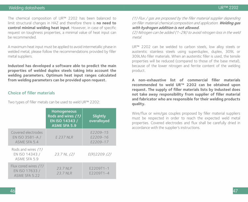
Choice of filler materials
Homogeneous Rods and wires (1)
EN ISO 14343 / ASME SFA 5.9
Slightly overalloyed
Covered electrodesEN ISO 3581-A /
ASME SFA 5.4E 237 NLR
E2209-15E2209-16E2209-17
Rods and wires (1)EN ISO 14343 / ASME SFA 5.9
23.7 NL (2) E(R)2209 (2)
Flux cored wires (1)EN ISO 17633 / ASME SFA 5.22
23.7 NLP23.7 NLR
E2209T1-1E2209T1-4
Two types of filler metals can be used to weld UR™ 2202:
UR™ 2202
(1) Flux / gas are proposed by the filler material supplier depending on filler material chemical composition and application. Welding gas with hydrogen addition is not allowed.(2) Nitrogen can be added (1-2%) to avoid nitrogen loss in the weld metal.
UR™ 2202 can be welded to carbon steels, low alloy steels or austenitic stainless steels using superduplex, duplex, 309L or 309LMo filler materials. When an austenitic filler is used, the tensile properties will be reduced (compared to those of the base metal), because of the lower nitrogen and ferrite content of the welding product.
A non-exhaustive list of commercial filler materials recommended to weld UR™ 2202 can be obtained upon request. The supply of filler materials lists by Industeel does not take away responsibility from supplier of filler material and fabricator who are responsible for their welding products quality.
Wire/flux or wire/gas couples proposed by filler material suppliers must be respected in order to reach the expected weld metal properties. Covered electrodes and flux shall be carefully dried in accordance with the supplier’s instructions.

Welding datasheets
48 49
Cleaning, pickling and passivation of welds
Cleaning of welded zones is commonly performed by chemical methods. Mechanical methods can be preliminarily used. Welds can be finely ground and polished, sand-blasted or micro-beaded (products without iron particles). Surface cleaning must be performed after pickling.
Pickling can be performed by immersion in a fluo-nitric bath (duration twice than that of 316L) or using a commercial pickling paste as for other stainless steels. These operations must be conducted with high security (ventilation, protective clothing and rubber gloves).
Heat treatment
UR™ 2202 is delivered in the solution-annealed and water-quenched condition (980/1080°C - 1800/1975°F). The chemical composition of UR™ 2202 is optimized in order to obtain, after heat treatment, nearly a 50% ferrite / 50% austenite microstructure.
These solution-annealing conditions must be respected for final or intermediate heat treatment in case of forming and when a solution-annealing or a stress-relieving treatment is required after welding.
UR™ 2202 duplex plates have to be treated after forming to restore the corrosion and mechanical properties of the material. In this case, final or intermediate heat treatment shall be carried out between 980 and 1080°C (1800 and 1975°F) following by rapid cooling (water quenching).
All other heat treatments, particularly those with holding times or with slow cooling rates in the 300 to 1000°C (570-1830°F) range must be avoided.
UR™ 2202
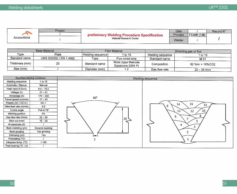
Example of pWPS
To show that the application of previous advices is possible, an example of a pWPS is provided. The parameters are coming from welds done by our teams.
Welding datasheets
50 51
UR™ 2202

Welding datasheets
52 53
3.2 UR™ 2304
UR™ 2304 is a lean duplex stainless steel with PREN value higher or equal to 24. The minimum guaranteed yield strength is 400 MPa (N/mm²) 58 KSI – which allows the designer to reduce thickness of equipment, compared to standard austenitics.
The alloy UR™ 2304 has a corrosion resistance similar or better than 316L. Furthermore, its mechanical properties i.e. yield strength, are twice those of 304/316 austenitic grades. This allows the designer to save weight, particularly for properly designed pressure vessel applications. The alloy is particularly suitable for applications covering the - 50°C/+300°C (- 58°F/572°F) temperature range. Lower temperatures may also be considered, but are subject to restrictions, particularly for welded structures. With its duplex microstructure, low nickel and high chromium contents, the alloy has improved stress corrosion resistance properties compared to 304 and 316. An enhanced version with a PREN ≥ 28 is also available on request.
UR™ 2304 is a cost efficient grade designed for: • Generally in substitution to 304L and 316L • Pulp and paper industry (chip storage tank, white and black liquor tanks...) • Caustic solutions, organic acids (SCC resistance) • Food industry • Safety panels (high mechanical properties) • Pressure vessels (weight savings...) • Mining (abrasion/corrosion)
StandardEN ISO 10028-7: 1.4362 – X2 Cr Ni N 23-4ASTM: A240 - UNS S32304ASME: SA240 – UNS S32304VDTUV Blatt: N° 496
UR™ 2304
C Cr Ni Mo N Others
0.02 23 4 0.2 0.14 S < 0.002
PREN = [Cr%] + 3.3[Mo%] + 16[N%] ≥ 24
Chemical AnalysisTypical values (weight %)
Hot formingHot forming should be carried out between 1150 and 950°C (2102 - 1742°F). Note that duplex stainless steels have a limited strength at high temperatures. Therefore, precautions must be taken to avoid possible deformation (wedging and support of pieces).If forming is finished above 950°C (1742°F) and cooling is fast enough (activated air or water) the final heat treatment can be avoided.When hot forming is applied to welds with 2304 or 2209 filler materials, a new heat treatment at 1050°C (1922°F) followed by rapid cooling (active air or water) is required.
Cold formingDue to its higher yield strength, forces required for the cold forming of UR™ 2304 are larger than for austenitic steels and a minimum bending diameter must be applied: •Minimum bending diameter = 3 x thickness for base metal; •Minimum bending diameter = 4 x thickness for a welded assembly.
Edges have to be ground and surfaces have to be carefully checked before cold forming.
A heat treatment (solution annealing between 1000 and 1070°C (1832 and 1958°F) followed by water-cooling) is always required when the final deformation by cold forming exceeds 10%. For cold deformation higher than 20%, an intermediate full-annealing heat treatment is required.
Forming
UR™ 2304 UR™ 2304
Welding datasheets
54 55
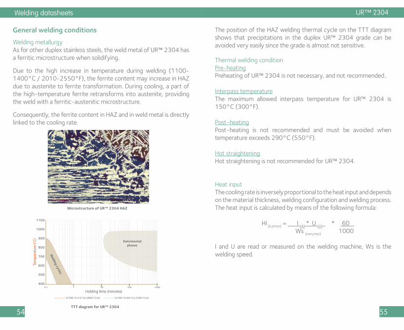
Welding metallurgyAs for other duplex stainless steels, the weld metal of UR™ 2304 has a ferritic microstructure when solidifying.
Due to the high increase in temperature during welding (1100-1400°C / 2010-2550°F), the ferrite content may increase in HAZ due to austenite to ferrite transformation. During cooling, a part of the high-temperature ferrite retransforms into austenite, providing the weld with a ferritic-austenitic microstructure.
Consequently, the ferrite content in HAZ and in weld metal is directly linked to the cooling rate.
General welding conditions The position of the HAZ welding thermal cycle on the TTT diagram shows that precipitations in the duplex UR™ 2304 grade can be avoided very easily since the grade is almost not sensitive.
Microstructure of UR™ 2304 HAZ
TTT diagram for UR™ 2304
Tem
pera
ture
(°C)
Holding time (minutes)
1100
1000
900
800
700
600
500
4000.1 1 10 100 1000
Vr700°C=15°C/s (900°C/h) Vr700°C=50°C/s (300°C/h)
Detrimentalphases
Welding cycles
UR™ 2304
Thermal welding conditionPre-heatingPreheating of UR™ 2304 is not necessary, and not recommended..
Interpass temperatureThe maximum allowed interpass temperature for UR™ 2304 is 150°C (300°F).
Post-heatingPost-heating is not recommended and must be avoided when temperature exceeds 290°C (550°F).
Hot straighteningHot straightening is not recommended for UR™ 2304.
Heat inputThe cooling rate is inversely proportional to the heat input and depends on the material thickness, welding configuration and welding process. The heat input is calculated by means of the following formula:
HI (kJ/mm)
= I (A)
* U (V)
* 60 Ws
(mm/min) 1000
I and U are read or measured on the welding machine, Ws is the welding speed.
Welding datasheets
56 57
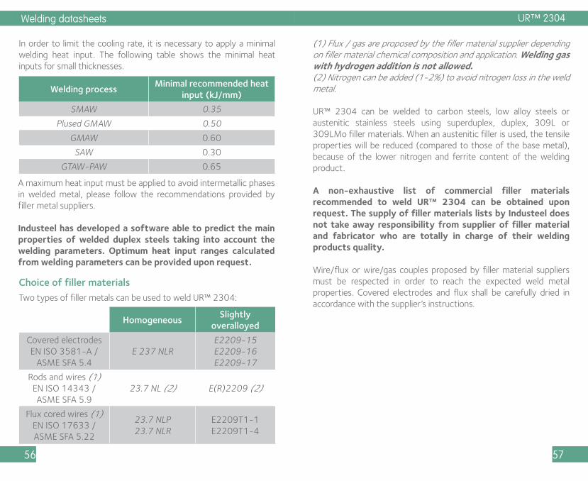
In order to limit the cooling rate, it is necessary to apply a minimal welding heat input. The following table shows the minimal heat inputs for small thicknesses.
A maximum heat input must be applied to avoid intermetallic phases in welded metal, please follow the recommendations provided by filler metal suppliers.
Industeel has developed a software able to predict the main properties of welded duplex steels taking into account the welding parameters. Optimum heat input ranges calculated from welding parameters can be provided upon request.
Welding processMinimal recommended heat
input (kJ/mm)
SMAW 0.35
Plused GMAW 0.50
GMAW 0.60
SAW 0.30
GTAW-PAW 0.65
Choice of filler materials
HomogeneousSlightly
overalloyed
Covered electrodesEN ISO 3581-A /
ASME SFA 5.4E 237 NLR
E2209-15E2209-16E2209-17
Rods and wires (1)EN ISO 14343 / ASME SFA 5.9
23.7 NL (2) E(R)2209 (2)
Flux cored wires (1)EN ISO 17633 / ASME SFA 5.22
23.7 NLP23.7 NLR
E2209T1-1E2209T1-4
Two types of filler metals can be used to weld UR™ 2304:
UR™ 2304
(1) Flux / gas are proposed by the filler material supplier depending on filler material chemical composition and application. Welding gas with hydrogen addition is not allowed.(2) Nitrogen can be added (1-2%) to avoid nitrogen loss in the weld metal.
UR™ 2304 can be welded to carbon steels, low alloy steels or austenitic stainless steels using superduplex, duplex, 309L or 309LMo filler materials. When an austenitic filler is used, the tensile properties will be reduced (compared to those of the base metal), because of the lower nitrogen and ferrite content of the welding product.
A non-exhaustive list of commercial filler materials recommended to weld UR™ 2304 can be obtained upon request. The supply of filler materials lists by Industeel does not take away responsibility from supplier of filler material and fabricator who are totally in charge of their welding products quality.
Wire/flux or wire/gas couples proposed by filler material suppliers must be respected in order to reach the expected weld metal properties. Covered electrodes and flux shall be carefully dried in accordance with the supplier’s instructions.
Welding datasheets
58 59
Cleaning, pickling and passivation of welds
Cleaning of welded zones is commonly performed by chemical methods. Mechanical methods can be preliminarily used. Welds can be finely ground and polished, sand-blasted or micro-beaded (products without iron particles). Surface cleaning must be performed after pickling.
Pickling can be performed by immersion in a fluo-nitric bath (duration twice than that of 316L) or using a commercial pickling paste as for others stainless steels. These operations must be conducted with high security (ventilation, protective clothing and rubber gloves).
Heat treatment
UR™ 2304 is delivered in the solution-annealed and water-quenched condition (950/1070°C - 1742/1958°F). The chemical composition of UR™ 2304 is optimized in order to obtain, after heat treatment, nearly a 50% ferrite / 50% austenite microstructure.
These solution-annealing conditions must be respected for final or intermediate heat treatment in case of forming and when a solution-annealing or a stress-relieving treatment is required after welding.
UR™ 2304 duplex plates have to be treated after forming to restore the corrosion and mechanical properties of the material. In this case, final or intermediate heat treatment shall be carried out between 950 and 1070°C (1742 and 1958°F) following by rapid cooling (water quenching).
All other heat treatments, particularly those with holding times or with slow cooling rates in the 300 to 1000°C (570-1830°F) range must be avoided.
UR™ 2304

Welding datasheets
60 61
3.3 UR™ 2205
UR™ 2205 is a duplex stainless steel with PREN value higher or equal to 33. The minimum guaranteed yield strength is 450 MPa (N/mm²) 65 KSI – which allows the designer to reduce thickness of equipment.
UR™ 2205 is a nitrogen alloyed (≥ 0.15%) austenitic-ferritic stainless steel with improved structure stability and high uniform, localized and stress corrosion resistance. This duplex, with 22% Cr and 3% Mo additions, performs much better than 316L grade in almost all corrosive media. The yield strength is about twice that of austenitic stainless steels. This allows the designer to save weight and makes the alloy more cost competitive compared to 316L grade. Typical operation temperatures are -50°C/+280°C (- 58°F/+536°F). Lower temperatures could be considered, but require additional precautions, in particular for welded structures.
UR™ 2205 is a cost efficient grade designed for: • Offshore • Marine • Pulp and Paper • Oil and Gas • Pollution control equipment • Chemical industry • Chemical tankers…
Standard
EN ISO 10028-7: 1.4462 – X2 Cr Ni Mo N 22-5-3ASTM: A240 – UNS S31803ASME: SA-240 – UNS S31803
UR™ 2205
C Cr Ni Mo N Others
0.02 22 5.3 2.8 0.16 S < 0.002
PREN = [Cr%] + 3.3[Mo%] + 16[N%] ≥ 33
Chemical AnalysisTypical values (weight %)
Hot formingHot forming should be carried out between 1150 and 950°C (2102 - 1750°F). Note that duplex stainless steels have a limited strength at high temperatures. Therefore, precautions must be taken to avoid possible deformation (wedging and support of pieces).
At temperatures lower than 950°C (1750°F), embrittlement can occur due to intermetallic phase precipitations, especially when the material is strained.After hot forming, a solution annealing heat treatment in the range 1040 - 1080°C (1904 - 1975°F) or 1080 -1090°C (1975 - 1995°F) if welded, with water cooling is necessary.
Cold formingDue to its higher yield strength, forces required for the cold forming of UR™ 2205 are larger than for austenitic steels and a minimum bending diameter must be applied: •Minimum bending diameter = 3 x thickness for base metal; •Minimum bending diameter = 4 x thickness for a welded assembly.
Edges have to be ground and surfaces have to be carefully checked before cold forming.
A heat treatment (solution annealing between 980 and 1080°C (1800 and 1975°F) followed by water-cooling) is always required when the final deformation by cold forming exceeds 10%. For cold deformation higher than 20%, an intermediate full-annealing heat treatment is required.
Forming
UR™ 2205

Welding datasheets
62 63
Welding metallurgyAs for other duplex stainless steels, the weld metal of UR™ 2205 has a ferritic microstructure when solidifying.
Due to the high increase in temperature during welding (1150-1450°C / 2102-2642°F), the ferrite content may increase in HAZ due to austenite to ferrite transformation. During cooling, a part of the high-temperature ferrite retransforms into austenite, providing the weld with a ferritic-austenitic microstructure.
Consequently, the ferrite content in HAZ and in weld metal is directly linked to the cooling rate.
General welding conditions At high temperature: 1000°-600°C (1830-1110°F), the ferrite may transform into intermetallic phases which makes the alloy brittle. At lower temperature (300-500°C - 570-930°F) the ferrite transforms in martensite resulting in a hardening of the structure after several hours holding time.
TTT diagram for UR™ 2205
Tem
pera
ture
(°C)
Holding time (minutes)
1100
1000
900
800
700
600
500
4000.1 1 10 100 1000
Vr700°C=15°C/s (900°C/h) Vr700°C=50°C/s (300°C/h)
Detrimentalphases
Welding cycles
UR™ 2205
Thermal welding conditionPre-heatingPreheating of UR™ 2205 is not necessary, and not recommended.
Interpass temperatureThe maximum allowed interpass temperature for UR™ 2205 is 150°C (300°F).
Post-heatingPost-heating is not recommended and must be avoided when temperature exceeds 290°C (550°F).
Hot straighteningHot straightening is not recommended for UR™ 2205.
Heat inputThe cooling rate is inversely proportional to the heat input and depends on the material thickness, welding configuration and welding process. The heat input is calculated by means of the following formula:
HI (kJ/mm)
= I (A)
* U (V)
* 60 Ws
(mm/min) 1000
I and U are read or measured on the welding machine, Ws is the welding speed.
Microstructure of UR™ 2205 HAZ

Welding datasheets
64 65
In order to limit the cooling rate, it is necessary to apply a minimal welding heat input. The following table shows the minimal heat inputs for 5 mm thick plates.
A maximum heat input must be applied to avoid intermetallic phase in welded metal, please follow the recommendations provided by filler metal suppliers.
Industeel has developed a software able to predict the main properties of welded duplex steels taking into account the welding parameters. Optimum heat input ranges calculated from welding parameters can be provided upon request.
Welding processMinimal recommended heat
input (kJ/mm)
SMAW 0.40
Plused GMAW 0.50
GMAW 0.50
SAW 0.30
GTAW-PAW 0.70
Choice of filler materials
Homogeneous Overalloyed (1)
Covered electrodesASME SFA 5.4
E2209-15 (3)E2209-16 (3)E2209-17 (3)
E2594-15E2594-16E2594-17
Rods and wires (2)ASME SFA 5.9
E(R)2209 (3) E(R)2594
Flux cored wires (2)ASME SFA 5.22
E2209T1-1 (3)E2209T1-4 (3)
E2594T1-1E2594T1-4
Two types of filler metals can be used to weld UR™ 2205:
UR™ 2205
(1) This solution gives to the weld metal an increased corrosion resistance.(2) Flux / gas are proposed by the filler material supplier depending on filler material chemical composition and application. Welding gas with hydrogen addition is not allowed. Nitrogen can be added (1-2%) to avoid nitrogen loss in the weld metal.(3) Classification specifies N content between 0,08% and 0,20%, but to keep good corrosion resistance and good austenite/ferrite equilibrium, we recommend a minimum content of 0,10% in deposited filler metal.
UR™ 2205 can be welded to carbon steels, low alloy steels or austenitic stainless steels using superduplex, duplex, 309L or 309LMo filler materials. When an austenitic filler is used, the tensile properties will be reduced (compared to those of the base metal), because of the lower nitrogen and ferrite content of the welding product.
A non-exhaustive list of commercial filler materials recommended to weld UR™ 2205 can be obtained upon request. The supply of filler materials lists by Industeel does not take away responsibility from supplier of filler material and fabricator who are totally responsible for their welding products quality.
Wire/flux or wire/gas couples proposed by filler material suppliers must be respected in order to reach the expected weld metal properties. Covered electrodes and flux shall be carefully dried in accordance with the supplier’s instructions.
UR™ 2205 UR™ 2205
Welding datasheets
66 67
Cleaning, pickling and passivation of welds
Cleaning of welded zones is commonly performed by chemical methods. Mechanical methods can be preliminarily used. Welds can be finely ground and polished, sand-blasted or micro-beaded (products without iron particles). Surface cleaning must be performed after pickling.
Pickling can be performed by immersion in a fluo-nitric bath (duration twice than that of 316L) or using a commercial pickling paste as for others stainless steels. These operations must be conducted with high security (ventilation, protective clothing and rubber gloves).
Heat treatment
UR™ 2205 is delivered in the solution-annealed and water-quenched condition (1040/1080°C - 1904/1975°F). The chemical composition of UR™ 2205 is optimized in order to obtain, after heat treatment, nearly a 50% ferrite / 50% austenite microstructure.
These solution-annealing conditions must be respected for final or intermediate heat treatment in case of forming. When a solution annealing or a stress relieving treatment is required after welding, the solution annealing with water cooling will be carried out in the temperature range 1080 -1090°C (1975 - 1995°F) taken into account the effect of the higher Ni content of the filler material on the secondary phases stability.
All other heat treatments, particularly those with holding times or with slow cooling rates in the 300 to 1000°C (570-1830°F) range must be avoided.
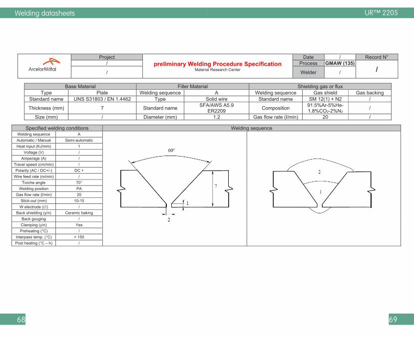
Example of pWPS
To show that the application of previous advices is possible, an example of a pWPS is provided. The parameters are coming from welds done by our teams.
UR™ 2205
Welding datasheets
68 69
UR™ 2205
Project preliminary Welding Procedure Specification
Material Research Center
Date / Record N° / Process GMAW (135)
/ / Welder /
Base Material Filler Material Shielding gas or flux Type Plate Welding sequence A Welding sequence Gas shield Gas backing
Standard name UNS S31803 / EN 1.4462 Type Solid wire Standard name SM 12(1) + N2 /
Thickness (mm) 7 Standard name SFA/AWS A5.9 ER2209 Composition 91.5%Ar-5%He-
1.8%CO2-2%N2 /
Size (mm) / Diameter (mm) 1.2 Gas flow rate (l/min) 20 /
Specified welding conditions Welding sequence Welding sequence A
Automatic / Manual Semi-automatic Heat input (KJ/mm) 1
Voltage (V) / Amperage (A) /
Travel speed (cm/min) / Polarity (AC / DC+/-) DC +
Wire feed rate (m/min) / Torche angle 70°
Welding position PA Gas flow rate (l/min) 20
Stick-out (mm) 10-15 W electrode () /
Back shielding (y/n) Ceramic baking Back gouging / Clamping (y/n) Yes Preheating (°C) /
Interpass temp. (°C) < 150 Post heating (°C – h) /

Welding datasheets
70 71
3.4 UR™ 2205Mo
UR™ 2205Mo is a duplex stainless steel with PREN value higher or equal to 35. The minimum guaranteed yield strength is 460 MPa (N/mm²) 65 KSI.
UR™ 2205Mo is a nitrogen alloyed (> 0.15%) austenitic - ferritic stainless steel with improved structure stability and high general, localised and stress corrosion resistance.This duplex, with 22% Cr and 3.1% Mo additions, performs much better than 316L grade in almost all corrosive media. The yield strength is about twice that of austenitic stainless steels. This allows the designer to save weight and makes the alloy more cost competitive when compared to 316L grade. Typical operating temperatures are - 50°C/+ 280°C (- 58°F/+536°F). Lower temperature could be considered but require additional precautions for welded structures.
UR™ 2205Mo is a cost efficient grade designed for: • Oil and Gas industry including sour gas applications • Pulp and Paper industry (digesters...) • Chemical industry (reactor vessels...) • Acetic acid distillation towers • Urea Production • Phosphoric acid plants (reactors...) • Sulphuric acid processes (hydrometallurgy...) • Pollution control equipments • Truck, lorries • Chemical tankers
Standard
EN ISO 10028-7: 1.4462 – X2 Cr Ni Mo N 22-5-3ASTM: A240 – UNS S31803 / UNS S32205ASME: SA-240 – UNS S31803 / UNS S32205
C Cr Ni Mo N Others
0.02 22.5 5.8 3.1 0.17 S < 0.002
PREN = [Cr%] + 3.3[Mo%] + 16[N%] ≥ 35
Chemical AnalysisTypical values (weight %)
Hot formingHot forming should be carried out between 1150 and 950°C (2102 - 1750°F). Note that duplex stainless steels have a limited strength at high temperatures. Therefore, precautions must be taken to avoid possible deformation (wedging and support of pieces).
A final full annealing heat treatment (1040/1080°C - 1900/1975°F) followed by rapid quenching is required (to restore phase balance, mechanical and corrosion resistance properties).
Cold formingDue to its higher yield strength, forces required for the cold forming of UR™ 2205Mo are larger than for austenitic steels and a minimum bending diameter must be applied: •Minimum bending diameter = 3 x thickness for base metal; • Minimum bending diameter = 4 x thickness for a welded assembly.
Edges have to be ground and surfaces have to be carefully checked before cold forming.
A heat treatment (solution annealing between 980 and 1080°C (1800 and 1975°F) followed by water-cooling) is always required when the final deformation by cold forming exceeds 10%. For cold deformation higher than 20%, an intermediate full-annealing heat treatment is required.
Forming
UR™ 2205Mo

Welding datasheets
72 73
Welding metallurgyAs for other duplex stainless steels, the weld metal of UR™ 2205Mo has a ferritic microstructure when solidifying.
Due to the high increase in temperature during welding (1150-1450°C / 2102-2642°F), the ferrite content may increase in HAZ due to austenite to ferrite transformation. During cooling, a part of the high-temperature ferrite retransforms into austenite, providing the weld with a ferritic-austenitic microstructure.
Consequently, the ferrite content in HAZ and in weld metal is directly linked to the cooling rate.
General welding conditions At high temperature: 1000-600°C (1830-1110°F), the ferrite may transform into intermetallic phases which makes the alloy brittle. At lower temperature (300-500°C - 570-930°F) the ferrite transforms in martensite resulting in a hardening of the structure after several hours holding time.
Microstructure of UR™ 2205Mo HAZ
TTT diagram for UR™ 2205Mo
Tem
pera
ture
(°C)
Holding time (minutes)
1100
1000
900
800
700
600
500
4000.1 1 10 100 1000
Vr700°C=15°C/s (900°C/h) Vr700°C=50°C/s (300°C/h)
Detrimentalphases
Welding cycles
UR™ 2205Mo
Thermal welding conditionPre-heatingPreheating of UR™ 2205Mo is not necessary, and not recommended..
Interpass temperatureThe maximum allowed interpass temperature for UR™ 2205Mo is 150°C (300°F).
Post-heatingPost-heating is not recommended and must be avoided when temperature exceeds 290°C (550°F).
Hot straighteningHot straightening is not recommended for UR™ 2205Mo .
Heat inputThe cooling rate is inversely proportional to the heat input and depends on the material thickness, welding configuration and welding process. The heat input is calculated by means of the following formula:
HI (kJ/mm)
= I (A)
* U (V)
* 60 Ws
(mm/min) 1000
I and U are read or measured on the welding machine, Ws is the welding speed.

Welding datasheets
74 75
The heat input must be controlled (about 10 to 25 kJ/cm is generally advised) in order to limit the cooling rate and to avoid intermetallic phase in welded metal. In addition, please follow the recommendations provided by filler metal suppliers.
Industeel has developed a software able to predict the main properties of welded duplex steels taking into account the welding parameters. Optimum heat input ranges calculated from welding parameters can be provided upon request.
Choice of filler materials
Homogeneous Overalloyed (1)
Covered electrodesASME SFA 5.4
E2209-15 (3)E2209-16 (3)E2209-17 (3)
E2594-15E2594-16E2594-17
Rods and wires (2)ASME SFA 5.9
E(R)2209 (3) E(R)2594
Flux cored wires (2)ASME SFA 5.22
E2209T1-1 (3)E2209T1-4 (3)
E2594T1-1E2594T1-4
Two types of filler metals can be used to weld UR™2205:
(1) This solution gives to the weld metal an increased corrosion resistance.(2) Flux / gas are proposed by the filler material supplier depending on filler material chemical composition and application. Welding gas with hydrogen addition is not allowed. Nitrogen can be added (1-2%) to avoid nitrogen loss in the weld metal.(3) Classification specifies N content between 0,08% and 0,20%, but to keep good corrosion resistance and good austenite/ferrite equilibrium, we recommend a minimum content of 0,10% in the filler metal.
UR™ 2205Mo
UR™ 2205Mo can be welded to carbon steels, low alloy steels or austenitic stainless steels using superduplex, duplex, 309L or 309LMo filler materials. When an austenitic filler is used, the tensile properties will be reduced (compared to those of the base metal), because of the lower nitrogen and ferrite content of the welding product.
A non-exhaustive list of commercial filler materials recommended to weld UR™ 2205Mo can be obtained upon request. The supply of filler materials lists by Industeel does not take away responsibility from supplier of filler material and fabricator who are responsible for their welding products quality.
Wire/flux or wire/gas couples proposed by filler material suppliers must be respected in order to reach the expected weld metal properties. Covered electrodes and flux shall be carefully dried in accordance with the supplier’s instructions.
UR™ 2205Mo UR™ 2205Mo UR™ 2205Mo

Welding datasheets
76 77
Cleaning, pickling and passivation of welds
Cleaning of welded zones is commonly performed by chemical methods. Mechanical methods can be preliminarily used. Welds can be finely ground and polished, sand-blasted or micro-beaded (products without iron particles). Surface cleaning must be performed after pickling.
Pickling can be performed by immersion in a fluo-nitric bath (duration twice than that of 316L) or using a commercial pickling paste as for others stainless steels. These operations must be conducted with high security (ventilation, protective clothing and rubber gloves).
Heat treatment
UR™ 2205Mo is delivered in the solution-annealed and water-quenched condition (1040/1080°C - 1904/1975°F). The chemical composition of UR™ 2205Mo is optimized in order to obtain, after heat treatment, nearly a 50% ferrite / 50% austenite microstructure.
These solution-annealing conditions must be respected for final or intermediate heat treatment in case of forming. When a solution annealing or a stress relieving treatment is required after welding, the solution annealing with water cooling will be carried out in the temperature range 1080 -1090°C (1975 - 1995°F) taken into account the effect of the higher Ni content of the filler material on the secondary phases stability.
All other heat treatments, particularly those with holding times or with slow cooling rates in the 300 to 1000°C (570-1830°F) range must be avoided.
UR™ 2205Mo

Welding datasheets
78 79
Standard
3.5 UR™ 2507
UR™ 2507 is a 25%Cr superduplex stainless steel with PREN value higher than 40. The minimum guaranteed yield strength is 550 MPa (N/mm²) 80 KSI.
The chromium, molybdenum and nitrogen contents have been optimized in order to obtain higher corrosion resistance properties compared to UR™ 904 and 6% Mo austenitics, even for the heaviest plates. Its high nitrogen addition improves the structure stability particularly in the HAZ.
UR™ 2507 is a cost efficient grade designed for Oil & Gas, marine, geothermal, refinering and petrochemical plants.
EN ISO 10028-7: 1.4410 – X2 Cr Ni Mo N 25-7-4ASTM: A240 – UNS S32750 ASME: SSA240 – UNS S32750
Chemical Analysis
Typical values (weight %)
C Cr Ni Mo N Others
< 0.030 25 6.5 3.6 0.26 S < 0.002
PREN = [Cr%] + 3.3[Mo%] + 16[N%] ≥ 40
UR™ 2507
Hot formingHot forming should be carried out between 1150 and 1000°C (2102 - 1832°F). Note that ferritic-austenitic stainless steels have a limited strength at high temperatures. Therefore, precautions must be taken to avoid possible deformation (wedging and support of pieces).
At temperatures below 1000°C (1832°F), embrittlement can appear due to intermetallic phase precipitations especially when the material is strained.
After hot forming, a new solution annealing heat treatment between 1080 and 1120°C (1976 – 2018°F) followed by water cooling is necessary.
Cold formingDue to its higher yield strength, forces required for the cold forming of UR™ 2507 are larger than for austenitic steels and a minimum bending diameter must be applied: •Minimum bending diameter = 3 x thickness for base metal; •Minimum bending diameter = 4 x thickness for a welded assembly.
Edges will be ground and surfaces (absence of scratches…) will be checked before cold forming.
A heat treatment (solution annealing between 1080 and 1120°C (1976 – 2018°F) followed by water-cooling is always required when the final deformation by cold forming exceeds 10%. For cold deformation higher than 20%, an intermediate full-annealing heat treatment is required.
Forming
UR™ 2507

Welding datasheets
80 81
Welding metallurgyAs for other duplex stainless steels, the weld metal of UR™ 2507 has a ferritic microstructure when solidifying.
Due to the high increase in temperature during welding (1100-1400°C / 2010-2550°F), the ferrite content may increase in HAZ due to austenite to ferrite transformation. During cooling, a part of the high-temperature ferrite retransforms into austenite, providing the weld with a ferritic-austenitic microstructure.
Consequently, the ferrite content in HAZ and in weld metal is directly linked to the cooling rate.
General welding conditions Due to the optimized chemical composition of UR™ 2507, the maximum ferrite content in the HAZ remains below 70% even with the highest cooling rate. In other word, there is no need to control minimal welding heat inputs.
For UR™ 2507 too low cooling rates could initiate ferrite transformation into intermetallic phases detrimental to the corrosion resistance and mechanical properties.
Microstructure of UR™ 2507 HAZ
TTT diagram for UR™ 2507
Tem
pera
ture
(°C)
Holding time (minutes)
1100
1000
900
800
700
600
500
4000.1 1 10 100 1000
Vr700°C=15°C/s (900°C/h) Vr700°C=50°C/s (300°C/h)
Detrimentalphases
Welding cycles
UR™ 2507
Thermal welding conditionPre-heatingPreheating of UR™ 2507 is not necessary, and not recommended..
Interpass temperatureThe maximum allowed interpass temperature for UR™2507 is 120°C (248°F).
Post-heatingPost-heating is not recommended and must be avoided when temperature exceeds 290°C (554°F).
Hot straighteningHot straightening is not recommended for UR™ 2507.
Heat inputThe cooling rate is inversely proportional to the heat input and depends on the material thickness, welding configuration and welding process. The heat input is calculated by means of the following formula:
HI (kJ/mm)
= I (A)
* U (V)
* 60 Ws
(mm/min) 1000
I and U are read or measured on the welding machine, Ws is the welding speed.

Welding datasheets
82 83
As explained before, there is no need to control the minimal welding heat inputs for UR™ 2507. However, a maximum heat input should be applied to avoid intermetallic phase in welded metal, please follow the recommendations provided by filler metal suppliers.
Industeel has developed a software able to predict the main properties of welded duplex steels taking into account the welding parameters. Optimum heat input ranges calculated from welding parameters can be provided upon request.
Choice of filler materials
Homogeneous Overalloyed (1)
Covered electrodesASME SFA 5.4 / 5.11
E2594-15E2594-16E2594-17E2595-15E2595-16E2595-17
ENiCrMo-10ENiCrMo-13
Rods and wires (2)ASME SFA 5.9 / 5.14
E(R)2594 (3) E(R)NiCrMo-10E(R)NiCrMo-13
Flux cored wires (2)ASME SFA 5.22 / 5.34
E2594T0-1E2594T0-4E2594T1-1E2594T1-4
Two types of filler metals can be used to weld UR™ 2507:
UR™ 2507
(1) A nickel alloy filler material improves the corrosion resistance of the weld metal, but gives lower tensile properties than the parent metal.(2) Flux / gas are proposed by the filler material supplier depending on filler material chemical composition and application. Welding gas with hydrogen addition is not allowed.(3) Nitrogen can be added (1-2%) to avoid nitrogen loss in the weld metal.
UR™ 2507 can be welded to carbon steels, low alloy steels or austenitic stainless steels using superduplex, duplex, 309L or 309LMo filler materials. When an austenitic filler is used, the tensile properties will be reduced (compared to those of the base metal), because of the lower nitrogen and ferrite content of the welding product. To weld UR™ 2507 with super-austenitic steels or nickel alloys, we advise to use nickel alloyed filler materials, with high chromium and molybdenum contents and without niobium.
A non-exhaustive list of commercial filler materials used to weld UR™ 2507 can be obtained on request from Industeel. The supply of filler materials lists by Industeel does not take away responsibility from supplier of filler material and fabricator who are responsible for their welding products quality.
Wire/flux or wire/gas couples proposed by filler material suppliers must be respected in order to reach the expected weld metal properties. Covered electrodes and flux shall be carefully dried in accordance with the supplier’s instructions.
Welding datasheets
84 85
Cleaning, pickling and passivation of welds
Cleaning of welded zones is commonly performed by chemical methods. Mechanical methods can be preliminarily used. Welds can be finely ground and polished, sand-blasted or micro-beaded (products without iron particles). Surface cleaning must be done after pickling.
Pickling can be performed by immersion in a fluo-nitric bath (duration twice than that of 316L) or using a commercial pickling paste as for others stainless steels. These operations must be conducted with high security (ventilation, protective clothing and rubber gloves).
Heat treatment
UR™ 2507 is delivered in the solution-annealed and water-quenched condition (1080/1120°C - 1976/2018°F). The chemical composition of UR™ 2507 is optimized in order to obtain, after heat treatment, nearly a 50% ferrite / 50% austenite microstructure.
These solution-annealing conditions must be respected for final or intermediate heat treatment in case of forming and when a solution-annealing or a stress-relieving treatment is required after welding.
All other heat treatments, particularly the one with holding time or with slow cooling in the 300 to 1000°C (572-1832°F) range must be avoided. Heat treatments at 400°C (742°F) used for dimensional stability of austenitic stainless steels are not acceptable for UR™ 2507.
UR™ 2507
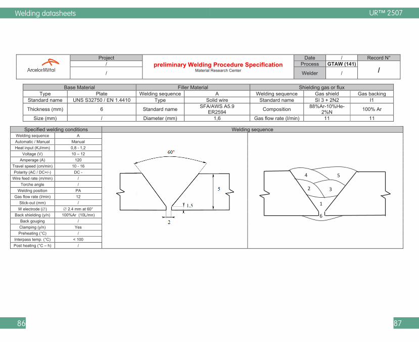
Example of pWPS
To show that the application of previous advices is possible, an example of a pWPS is provided. The parameters are coming from welds done by our teams.
Welding datasheets
86 87
UR™ 2507
Project preliminary Welding Procedure Specification
Material Research Center
Date / Record N° / Process GTAW (141)
/ / Welder /
Base Material Filler Material Shielding gas or flux Type Plate Welding sequence A Welding sequence Gas shield Gas backing
Standard name UNS S32750 / EN 1.4410 Type Solid wire Standard name SI 3 + 2N2 I1
Thickness (mm) 6 Standard name SFA/AWS A5.9 ER2594 Composition 88%Ar-10%He-
2%N 100% Ar
Size (mm) / Diameter (mm) 1,6 Gas flow rate (l/min) 11 11
Specified welding conditions Welding sequence Welding sequence A
Automatic / Manual Manual Heat input (KJ/mm) 0,8 - 1,2
Voltage (V) 10 – 12 Amperage (A) 120
Travel speed (cm/min) 10 - 16 Polarity (AC / DC+/-) DC -
Wire feed rate (m/min) / Torche angle /
Welding position PA Gas flow rate (l/min) 12
Stick-out (mm) / W electrode () 2.4 mm at 60°
Back shielding (y/n) 100%Ar (10L/mn) Back gouging / Clamping (y/n) Yes Preheating (°C) /
Interpass temp. (°C) < 100 Post heating (°C – h) /
1
3
4 5
2
6
Welding datasheets
88 89
Standard
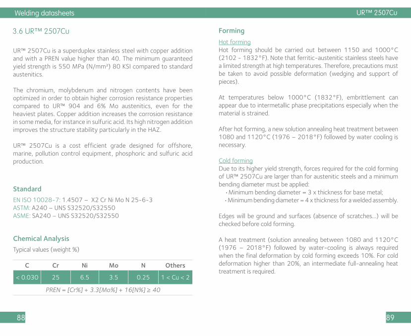
3.6 UR™ 2507Cu
UR™ 2507Cu is a superduplex stainless steel with copper addition and with a PREN value higher than 40. The minimum guaranteed yield strength is 550 MPa (N/mm²) 80 KSI compared to standard austenitics.
The chromium, molybdenum and nitrogen contents have been optimized in order to obtain higher corrosion resistance properties compared to UR™ 904 and 6% Mo austenitics, even for the heaviest plates. Copper addition increases the corrosion resistance in some media, for instance in sulfuric acid. Its high nitrogen addition improves the structure stability particularly in the HAZ.
UR™ 2507Cu is a cost efficient grade designed for offshore, marine, pollution control equipment, phosphoric and sulfuric acid production.
EN ISO 10028-7: 1.4507 – X2 Cr Ni Mo N 25-6-3ASTM: A240 – UNS S32520/S32550 ASME: SA240 – UNS S32520/S32550
Chemical Analysis
Typical values (weight %)
C Cr Ni Mo N Others
< 0.030 25 6.5 3.5 0.25 1 < Cu < 2
PREN = [Cr%] + 3.3[Mo%] + 16[N%] ≥ 40
Hot formingHot forming should be carried out between 1150 and 1000°C (2102 - 1832°F). Note that ferritic-austenitic stainless steels have a limited strength at high temperatures. Therefore, precautions must be taken to avoid possible deformation (wedging and support of pieces).
At temperatures below 1000°C (1832°F), embrittlement can appear due to intermetallic phase precipitations especially when the material is strained.
After hot forming, a new solution annealing heat treatment between 1080 and 1120°C (1976 – 2018°F) followed by water cooling is necessary.
Cold formingDue to its higher yield strength, forces required for the cold forming of UR™ 2507Cu are larger than for austenitic steels and a minimum bending diameter must be applied: •Minimum bending diameter = 3 x thickness for base metal; •Minimum bending diameter = 4 x thickness for a welded assembly.
Edges will be ground and surfaces (absence of scratches…) will be checked before cold forming.
A heat treatment (solution annealing between 1080 and 1120°C (1976 – 2018°F) followed by water-cooling is always required when the final deformation by cold forming exceeds 10%. For cold deformation higher than 20%, an intermediate full-annealing heat treatment is required.
Forming
UR™ 2507Cu
Welding datasheets
90 91
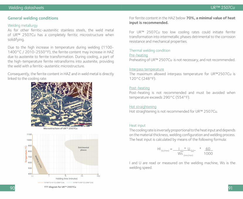
Welding metallurgyAs for other ferritic-austenitic stainless steels, the weld metal of UR™ 2507Cu has a completely ferritic microstructure when solidifying.
Due to the high increase in temperature during welding (1100-1400°C / 2010-2550°F), the ferrite content may increase in HAZ due to austenite to ferrite transformation. During cooling, a part of the high-temperature ferrite retransforms into austenite, providing the weld with a ferritic-austenitic microstructure.
Consequently, the ferrite content in HAZ and in weld metal is directly linked to the cooling rate.
General welding conditions For ferrite content in the HAZ below 70%, a minimal value of heat input is recommended.
For UR™ 2507Cu too low cooling rates could initiate ferrite transformation into intermetallic phases detrimental to the corrosion resistance and mechanical properties.
Microstructure of UR™ 2507Cu
TTT diagram for UR™ 2507Cu
Tem
pera
ture
(°C
)
Holding time (minutes)
1100
1000
900
800
700
600
500
4000.1 1 10 100 1000
Vr700°C=15°C/s (900°C/h) Vr700°C=50°C/s (300°C/h)
Detrimentalphases
Welding cycles
UR™ 2507Cu
Thermal welding conditionPre-heatingPreheating of UR™ 2507Cu is not necessary, and not recommended.
Interpass temperatureThe maximum allowed interpass temperature for UR™2507Cu is 120°C (248°F).
Post-heatingPost-heating is not recommended and must be avoided when temperature exceeds 290°C (554°F).
Hot straighteningHot straightening is not recommended for UR™ 2507Cu.
Heat inputThe cooling rate is inversely proportional to the heat input and depends on the material thickness, welding configuration and welding process. The heat input is calculated by means of the following formula:
HI (kJ/mm)
= I (A)
* U (V)
* 60 Ws
(mm/min) 1000
I and U are read or measured on the welding machine, Ws is the welding speed.

Welding datasheets
92 93
A maximum heat input must be applied to avoid intermetallic phase in welded metal, please follow the recommendations provided by filler metal suppliers.
Industeel has developed a software able to predict the main properties of welded duplex steels taking into account the welding parameters. Optimum heat input ranges calculated from welding parameters can be provided upon request.
The graph hereafter, shows the minimum heat input values which can be used to have limited ferrite content in HAZ, for a butt weld, according to welding process, and plate thickness.
UR™ 2507Cu
Choice of filler materials
Homogeneous Overalloyed (1)
Covered electrodesASME SFA 5.4 / 5.11
E2594-15E2594-16E2594-17E2595-15E2595-16E2595-17
ENiCrMo-10ENiCrMo-13
Rods and wires (2)ASME SFA 5.9 / 5.14
E(R)2594 (3) E(R)NiCrMo-10E(R)NiCrMo-13
Flux cored wires (2)ASME SFA 5.22 / 5.34
E2594T0-1E2594T0-4E2594T1-1E2594T1-4
Two types of filler metals can be used to weld UR™ 2507Cu:
(1) A nickel alloy filler material improves the corrosion resistance of the weld metal, but gives lower tensile properties than the parent metal.(2) Flux / gas are proposed by the filler material supplier depending on filler material chemical composition and application. Welding gas with hydrogen addition is not allowed.(3) Nitrogen can be added (1-2%) to avoid nitrogen loss in the weld metal.

Welding datasheets
94 95
UR™ 2507Cu can be welded to carbon steels, low alloy steels or austenitic stainless steels using superduplex, duplex, 309L or 309LMo filler materials. When an austenitic filler is used, the tensile properties will be reduced (compared to those of the base metal), because of the lower nitrogen and ferrite content of the welding product. To weld UR™ 2507 with super-austenitic steels or nickel alloys, we advise to use nickel alloyed filler materials, with high chromium and molybdenum contents and without niobium.
A non-exhaustive list of commercial filler materials used to weld UR™ 2507 can be obtained on request from Industeel. The supply of filler materials lists by Industeel does not take away responsibility from supplier of filler material and fabricator who are responsible for their welding products quality.
Wire/flux or wire/gas couples proposed by filler material suppliers must be respected in order to reach the expected weld metal properties. Covered electrodes and flux shall be carefully dried in accordance with the supplier’s instructions.
UR™ 2507Cu
Cleaning, pickling and passivation of welds
Cleaning of welded zones is commonly performed by chemical methods. Mechanical methods can be preliminarily used. Welds can be finely ground and polished, sand-blasted or micro-beaded (products without iron particles). Surface cleaning must be realized after pickling.
Pickling can be performed by immersion in a fluo-nitric bath (duration twice than that of 316L) or using a commercial pickling paste as for others stainless steels. These operations must be conducted with high security (ventilation, protective clothing and rubber gloves).
Heat treatment
UR™ 2507Cu is delivered in the solution-annealed and water-quenched condition (1080/1120°C - 1976/2018°F). The chemical composition of UR™ 2507Cu is optimized in order to obtain, after heat treatment, nearly a 50% ferrite / 50% austenite microstructure.
These solution-annealing conditions must be respected for final or intermediate heat treatment in case of forming and when a solution-annealing or a stress-relieving treatment is required after welding.
All other heat treatments, particularly the one with holding time or with slow cooling in the 300 to 1000°C (572-1832°F) range must be avoided. Heat treatments at 400°C (742°F) used for dimensional stability of austenitic stainless steels are not acceptable for UR™ 2507Cu.

Welding datasheets
96 97
Standard
3.7 UR™ 2507W
UR™ 2507W is a 25Cr superduplex stainless steel with copper & tungsten additions and with a PREN value higher than 40. The minimum guaranteed yield strength is 550 MPa (N/mm²) 80 KSI compared to standard austenitics.
The chromium, molybdenum and nitrogen contents have been optimized in order to obtain higher corrosion resistance properties compared to UR™ 904 and 6% Mo austenitics, even for the heaviest plates. Copper and tungsten additions increase the localized corrosion resistance. Its nitrogen addition improves the structure stability particularly in the HAZ.
UR™ 2507W is a cost efficient grade designed for offshore, marine, pollution control equipment, phosphoric and sulfuric acid production.
EN ISO 10028-7: 1 1.4501 – X2 Cr Ni Mo N 25-7-4ASTM: A240 – UNS S32760ASME: SA240 – UNS S32760
Chemical Analysis
Typical values (weight %)
C Cr Ni Mo N Others
< 0.030 25 7 3.4 0.23Cu 0.8 W 0.8
PREN = [Cr%] + 3.3[Mo%] + 16[N%] ≥ 40
Hot formingHot forming should be carried out between 1150 and 1000°C (2102 - 1832°F). Note that ferritic-austenitic stainless steels have a limited strength at high temperatures. Therefore, precautions must be taken to avoid possible deformation (wedging and support of pieces).
At temperatures below 1000°C (1832°F), embrittlement can appear due to intermetallic phase precipitations especially when the material is strained.
After hot forming, a new solution annealing heat treatment between 1080 and 1120°C (1976 – 2018°F) followed by water cooling is necessary.
Cold formingDue to its higher yield strength, forces required for the cold forming of UR™ 2507W are larger than for austenitic steels and a minimum bending diameter must be applied: •Minimum bending diameter = 3 x thickness for base metal; •Minimum bending diameter = 4 x thickness for a welded assembly.
Edges will be ground and surfaces (absence of scratches…) will be checked before cold forming.
A heat treatment (solution annealing between 1080 and 1120°C (1976 – 2018°F) followed by water-cooling is always required when the final deformation by cold forming exceeds 10%. For cold deformation higher than 20%, an intermediate full-annealing heat treatment is required.
Forming
UR™ 2507W
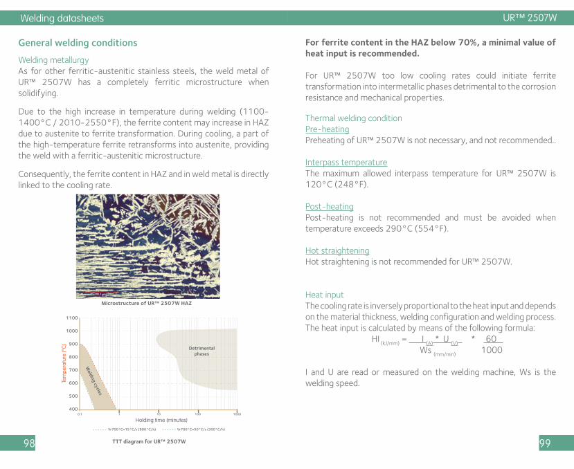
Welding datasheets
98 99
Welding metallurgyAs for other ferritic-austenitic stainless steels, the weld metal of UR™ 2507W has a completely ferritic microstructure when solidifying.
Due to the high increase in temperature during welding (1100-1400°C / 2010-2550°F), the ferrite content may increase in HAZ due to austenite to ferrite transformation. During cooling, a part of the high-temperature ferrite retransforms into austenite, providing the weld with a ferritic-austenitic microstructure.
Consequently, the ferrite content in HAZ and in weld metal is directly linked to the cooling rate.
General welding conditions For ferrite content in the HAZ below 70%, a minimal value of heat input is recommended.
For UR™ 2507W too low cooling rates could initiate ferrite transformation into intermetallic phases detrimental to the corrosion resistance and mechanical properties.
Microstructure of UR™ 2507W HAZ
TTT diagram for UR™ 2507W
Tem
pera
ture
(°C)
Holding time (minutes)
1100
1000
900
800
700
600
500
4000.1 1 10 100 1000
Vr700°C=15°C/s (900°C/h) Vr700°C=50°C/s (300°C/h)
Detrimentalphases
Welding cycles
UR™ 2507W
Thermal welding conditionPre-heatingPreheating of UR™ 2507W is not necessary, and not recommended..
Interpass temperatureThe maximum allowed interpass temperature for UR™ 2507W is 120°C (248°F).
Post-heatingPost-heating is not recommended and must be avoided when temperature exceeds 290°C (554°F).
Hot straighteningHot straightening is not recommended for UR™ 2507W.
Heat inputThe cooling rate is inversely proportional to the heat input and depends on the material thickness, welding configuration and welding process. The heat input is calculated by means of the following formula: HI
(kJ/mm) = I
(A) * U
(V) * 60
Ws (mm/min)
1000
I and U are read or measured on the welding machine, Ws is the welding speed.

Welding datasheets
100 101
A maximum heat input must be applied to avoid intermetallic phase in welded metal, please follow the recommendations provided by filler metal suppliers.
Industeel has developed a software able to predict the main properties of welded duplex steels taking into account the welding parameters. Optimum heat input ranges calculated from welding parameters can be provided upon request.
The graph hereafter, shows the minimum heat input values which can be used to have limited ferrite content in HAZ, for a butt weld, according to welding process, and plate thickness.
UR™ 2507W
Choice of filler materials
Homogeneous Overalloyed (1)
Covered electrodesASME SFA 5.4 / 5.11
E2594-15E2594-16E2594-17E2595-15E2595-16E2595-17
ENiCrMo-10ENiCrMo-13
Rods and wires (2)ASME SFA 5.9 / 5.14
E(R)2594 (3) E(R)NiCrMo-10E(R)NiCrMo-13
Flux cored wires (2)ASME SFA 5.22 / 5.34
E2594T0-1E2594T0-4E2594T1-1E2594T1-4
Two types of filler metals can be used to weld UR™ 2507W:
(1) A nickel alloy filler material improves the corrosion resistance of the weld metal, but gives lower tensile properties than the parent metal.(2) Flux / gas are proposed by the filler material supplier depending on filler material chemical composition and application. Welding gas with hydrogen addition is not allowed.(3) Nitrogen can be added (1-2%) to avoid nitrogen loss in the weld metal.

Welding datasheets
102 103
A non-exhaustive list of commercial filler materials used to weld UR™ 2507 can be obtained on request from Industeel. The supply of filler materials lists by Industeel does not take away responsibility from supplier of filler material and fabricator who are responsible for their welding products quality.
Wire/flux or wire/gas couples proposed by filler material suppliers must be respected in order to reach the expected weld metal properties. Covered electrodes and flux shall be carefully dried in accordance with the supplier’s instructions.
Cleaning, pickling and passivation of welds
Cleaning of welded zones is commonly performed by chemical methods. Mechanical methods can be preliminarily used. Welds can be finely ground and polished, sand-blasted or micro-beaded (products without iron particles). Surface cleaning must be realized after pickling.
Pickling can be performed by immersion in a fluo-nitric bath (duration twice than that of 316L) or using a commercial pickling paste as for others stainless steels. These operations must be conducted with high security (ventilation, protective clothing and rubber gloves).
Heat treatment
UR™ 2507W is delivered in the solution-annealed and water-quenched condition (1080/1120°C - 1976/2018°F). The chemical composition of UR™ 2507W is optimized in order to obtain, after heat treatment, nearly a 50% ferrite / 50% austenite microstructure.
These solution-annealing conditions must be respected for final or intermediate heat treatment in case of forming and when a solution-annealing or a stress-relieving treatment is required after welding.
All other heat treatments, particularly the one with holding time or with slow cooling in the 300 to 1000°C (572-1832°F) range must be avoided. Heat treatments at 400°C (742°F) used for dimensional stability of austenitic stainless steels are not acceptable for UR™ 2507W.

Welding qualification
104 105
4. Properties prediction software
Industeel has developed a database software using 40 years of welding data to predict the properties of a duplex weld, based on the welding procedure and chemical composition of the base and filler materials. This tool is available upon request and will help improve your welding procedures for optimized weld properties.
Properties prediction software
The software can predict the maximum ferrite content in the weld and HAZ, the primary solidification structure, the corrosion properties (critical pitting temperature according to ASTM G48), the mechanical properties, the hot cracking sensitivity and nitrogen solubility.

Notes : Notes :

Notes : Notes :
All information in this brochure is for the purpose of information only.Industeel reserves the right to change its product range at any time without prior notice.
Industeel FranceLe Creusot plant56, rue Clemenceau - BP 19F - 71201 LE CREUSOT Cedex FRANCETel : + 33 3 85 80 50 14
https://industeel.arcelormittal.com