Dungog clear water tanks visualisation study - … · DUNGOG CLEAR WATER TANKS VISUALISATION STUDY...
23
Dungog clear water tanks visualisation study Prepared for Hunter Water Corporation July 2009
-
Upload
truongkhuong -
Category
Documents
-
view
221 -
download
0
Transcript of Dungog clear water tanks visualisation study - … · DUNGOG CLEAR WATER TANKS VISUALISATION STUDY...
Dungog clear water tanks visualisation study
Prepared for Hunter Water Corporation July 2009

MANIDIS ROBERTS PTY LTD ABN 42 003 550 972
Level 9, 17 York Street, Sydney NSW 2000 GPO Box 91, Sydney NSW 2001
t (02) 9248 9800 f (02) 9248 9810 [email protected] www.manidisroberts.com.au
Quality control Our reference 09002 Version number 2.0 Date 22 July 2009
Contents 1 Executive summary 1
2 Project scope 2 2.1 Project background 2 2.2 Clear water tank location 2 2.3 Visual amenity issues of development 5 2.4 Project scope and understanding 5
3 Data review and modelling 6 3.1 Document and data review 6 3.2 Desktop viewshed analysis 6 3.3 Mapping 7
4 Receptor analysis 8 4.1 Dungog clear water tanks visual catchment generation 8 4.2 Receptor analysis – Dungog township 9 4.3 Receptor analysis – photo location points 11 4.4 Receptor analysis – local residents 17
5 Conclusion 20
DUNGOG CLEAR WATER TANKS VISUALISATION STUDY PREPARED FOR HUNTER WATER CORPORATION
VERSION 2.0 1
1 Executive summary
Hunter Water intends constructing a 30 megalitre (ML) clear water storage facility adjacent to the Dungog Water Treatment Plant (WTP). Hunter Water has developed a concept design providing two options for supplying the required 30ML storage capacity. The clear water tank(s) for both options will be constructed of non-reflective steel.
The clear water tanks will be a significant feature in the existing topography, which is rural in character consisting of partially cleared rolling hills, rural homesteads and work sheds. The tanks will impact the visual amenity for users of Clarence Town Road, Wade Street and Short Street in addition to numerous properties.
The results of a GIS (geographical information system) visualisation study of the location of Dungog’s clear water tanks, following concept Option B – two 15ML clear water tanks each 47m in diameter and 11m high – are summarised in a series of maps presented throughout this report.
Large scale maps demonstrating the LiDAR-generated visual catchments over an aerial photography base have been generated using ground surface data, due to limitations in the density of first-return data.
LiDAR-generated visual catchments for the southern part of Dungog township intersecting the study area of interest represent approximately ten properties as having some degree of visual impact from the clear water tanks. Landscaping, buildings and orientation of properties (only two are west-facing) may further mitigate any potential visual impact for these potentially impacted properties, as viewshed analyses have been carried out using ground surface data as stated above.
In order to provide a representative indication of the likely extent of visual impact in the surrounding countryside four key viewpoints have been selected for the preparation of photomontages of the clear water tanks by Hunter Water Corporation: from Wade Street to the clear water tanks, from Clarence Town Road and from Cemetery Road. The photomontages have been designed to represent an unmitigated visual impact as no vegetative screening has been modelled. The clear water tanks can be seen from each of the four viewpoints, as can residents proximal to the viewpoints.
Within a three kilometre radius of the clear water tanks five areas located outside of Dungog township were identified as potentially sensitive receptor areas. Of these only the three lying directly south of the clear water tanks will experience a degree of visual impact as terrain mitigates the view toward the clear water tanks for the other two areas reviewed. Within one kilometre of the clear water tanks this represents a cluster of four buildings north of Cemetery Road, five buildings proximal to the photo viewpoints as well as an additional six buildings within 300-600m of the clear water tank development, not all of which appear residential.
DUNGOG CLEAR WATER TANKS VISUALISATION STUDY PREPARED FOR HUNTER WATER CORPORATION
VERSION 2.0 2
2 Project scope
2.1 Project background
Hunter Water intends constructing a 30 megalitre (ML) clear water storage facility adjacent to the Dungog Water Treatment Plant (WTP).
The existing clear water tank (CWT) at the water treatment plant holds 6ML of treated water, suitable for consumption. This volume of water is sufficient for providing 1 hour of maximum capacity supply in the event of emergency closure of the WTP, such as might occur if supply water does not meet the required water quality standards.
Hunter Water Corporation has been notified by the Hunter New England Area Health Service that the existing clear water emergency supply availability is not adequate to meet the potential requirements of consumers in the Dungog, Maitland, Cessnock and Newcastle areas. As a result, the construction of an additional 30ML clear water storage capacity is proposed. The Dungog clear water storage facility will ultimately reduce the risk of potable water supply failure affecting customers in Dungog, Cessnock, Maitland and Newcastle.
Hunter Water has developed a concept design providing two options for supplying the required 30ML storage capacity. The clear water tank(s) for both options will be constructed of non-reflective steel. Option A (single 30ML CWT) would be 64m diameter and 11m high, for Option B (two 15ML CWTs) each tank would be 47m diameter, 11m high and the north-south extent of visual impact would be 98m.
2.2 Clear water tank location
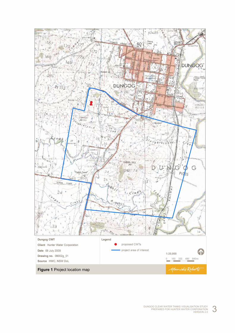
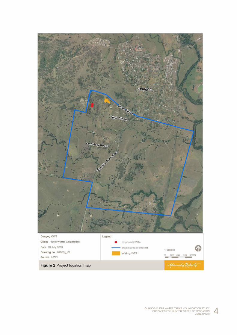
The project site is located immediately west of the existing Dungog water treatment plant and the Chichester trunk gravity main, approximately 1.5km south west of Dungog town centre. The site is bounded by Wade Street to the south and a travelling stock reserve off Short Street to the North, with access via Wade Street, which links to Clarence Town Road. See Figures 1 and 2.
DUNGOG CLEAR WATER TANKS VISUALISATION STUDY PREPARED FOR HUNTER WATER CORPORATION
VERSION 2.0 3
DUNGOG CLEAR WATER TANKS VISUALISATION STUDY PREPARED FOR HUNTER WATER CORPORATION
VERSION 2.0 4
DUNGOG CLEAR WATER TANKS VISUALISATION STUDY PREPARED FOR HUNTER WATER CORPORATION
VERSION 2.0 5
2.3 Visual amenity issues of development
The existing visual amenity of the Dungog area is rural in character consisting of partially cleared rolling hills, rural homesteads and work sheds.
The clear water tank development site is largely cleared, but with a few paddock trees located randomly throughout the property.
The project will require the removal of two large trees located on the hillside and a stand of approximately 20 smaller regrowth trees located in the northeastern gully.
The clear water tanks will be a significant feature in the existing topography. The tanks will impact the visual amenity for users of Clarence Town Road, Wade Street and Short Street in addition to numerous properties.
2.4 Project scope and understanding
The visualisation study of the Dungog clear water tanks undertakes generation of an independent desktop assessment (using a geographical information system (GIS)) of the visual catchment of the proposed clear water tanks. The assessment will principally be carried out for the study area of interest defined by Hunter Water Corporation and based on Option B – two 15ML clear water tanks each 47m in diameter and 11m high.
DUNGOG CLEAR WATER TANKS VISUALISATION STUDY PREPARED FOR HUNTER WATER CORPORATION
VERSION 2.0 6
3 Data review and modelling
A visualisation study is a desktop assessment using available elevation data, topography and imagery in a GIS. The visualisation study process undertaken for the Dungog clear water tanks is outlined below.
3.1 Document and data review
A desktop review is conducted of document and data resources relevant to the project. Review of relevant resources for the Dungog clear water tanks includes:
• Available aerial imagery and raw LiDAR data.
• Topographic, elevation point and contour data.
• Cadastral data and title relevant to identified receptors.
• Advised community boundaries for investigations, including study area of interest.
• Photomontages of modelled CWTs generated by Hunter Water Corporation from viewpoints on Wade Street, Clarence Town Road and Cemetery Road.
• Data pertaining to clear water tank geometry and location, and of any related infrastructure.
• Reference material relating to the clear water tank(s) and preliminary environmental investigations.
3.2 Desktop viewshed analysis
Viewshed analysis is carried out within the study area provided to determine visual catchments for receptors for the Dungog clear water tanks. All viewshed analysis is conducted using GIS which enables:
• Terrain analysis.
• Grid and contour, grid mathematics.
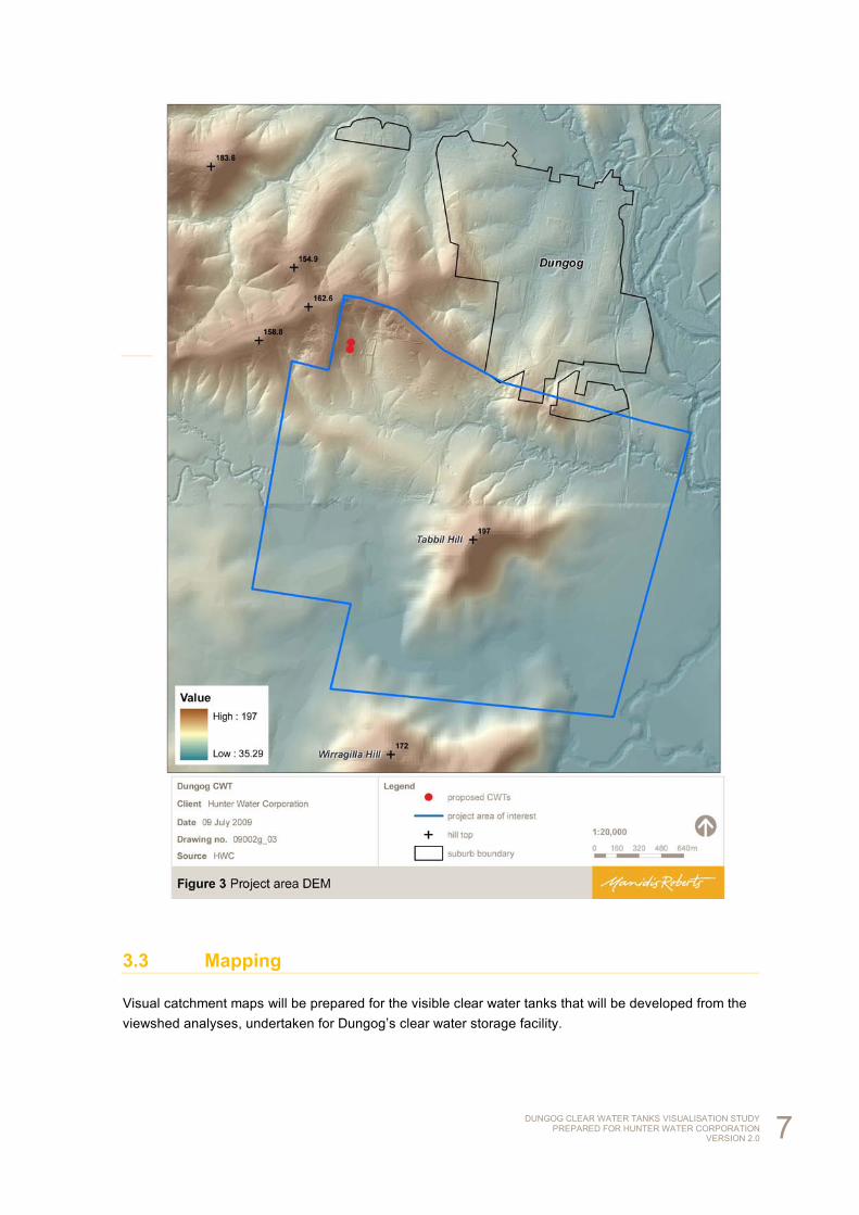
• Generation of a digital elevation model (DEM) from elevation data. This is demonstrated in Figure 3, including a demarcation between the scales of available elevation data for the northern and southern parts of the study area of interest.
• Extruding features (point to line/line to fence/polygon to solid).
• Generating landscape profile (longitudinal sections), showing ‘line of sight’ for receptors.
• LiDAR ground data merged with 25m digital terrain model.
• Raster sampling of LiDAR TIN at 1m pixel resolution.
• Calculating areas and volumes.
• Surface analysis – hill shade, slope, aspect – to investigate elevation and LiDAR correlation and any data anomalies.
DUNGOG CLEAR WATER TANKS VISUALISATION STUDY PREPARED FOR HUNTER WATER CORPORATION
VERSION 2.0 7
3.3 Mapping
Visual catchment maps will be prepared for the visible clear water tanks that will be developed from the viewshed analyses, undertaken for Dungog’s clear water storage facility.
DUNGOG CLEAR WATER TANKS VISUALISATION STUDY PREPARED FOR HUNTER WATER CORPORATION
VERSION 2.0 8
4 Receptor analysis
4.1 Dungog clear water tanks visual catchment generation
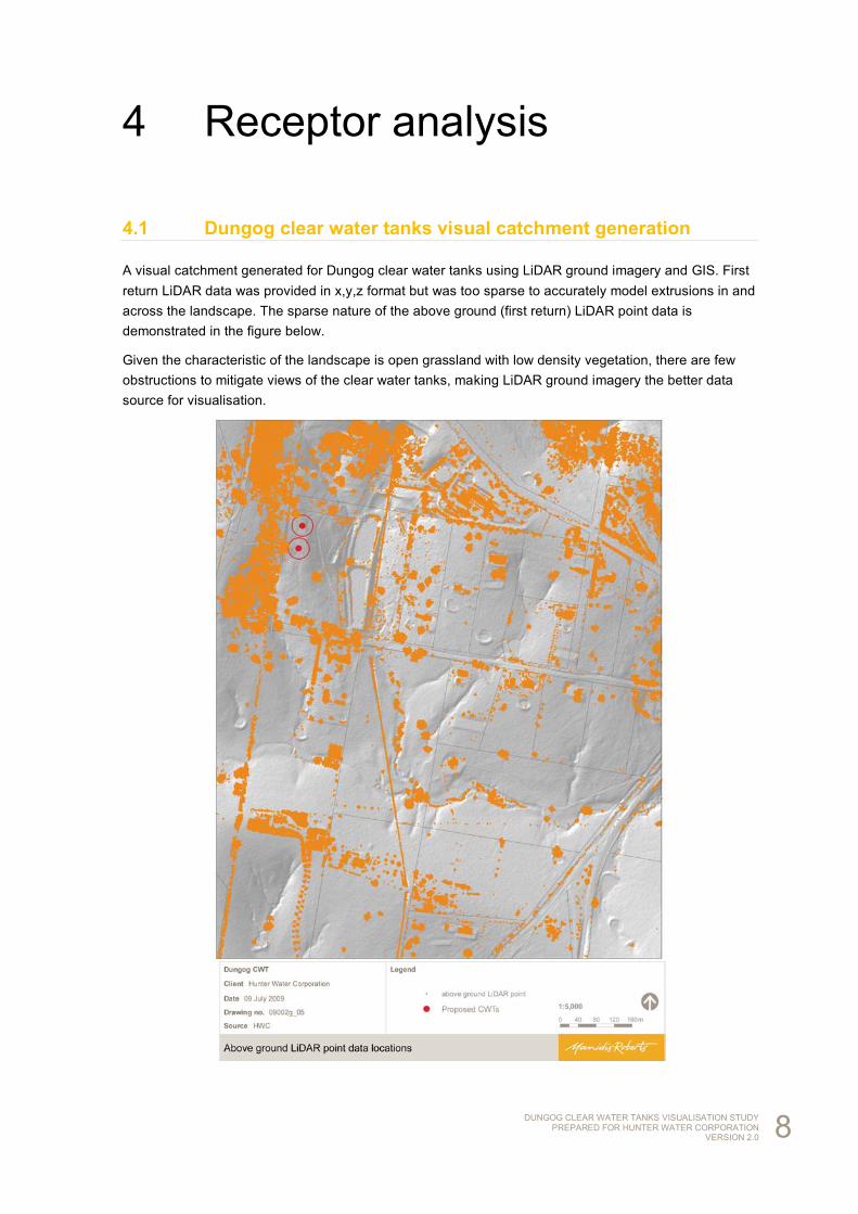
A visual catchment generated for Dungog clear water tanks using LiDAR ground imagery and GIS. First return LiDAR data was provided in x,y,z format but was too sparse to accurately model extrusions in and across the landscape. The sparse nature of the above ground (first return) LiDAR point data is demonstrated in the figure below.
Given the characteristic of the landscape is open grassland with low density vegetation, there are few obstructions to mitigate views of the clear water tanks, making LiDAR ground imagery the better data source for visualisation.
DUNGOG CLEAR WATER TANKS VISUALISATION STUDY PREPARED FOR HUNTER WATER CORPORATION
VERSION 2.0 9
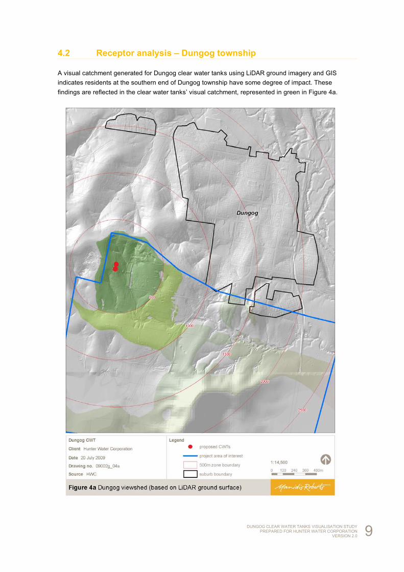
4.2 Receptor analysis – Dungog township
A visual catchment generated for Dungog clear water tanks using LiDAR ground imagery and GIS indicates residents at the southern end of Dungog township have some degree of impact. These findings are reflected in the clear water tanks’ visual catchment, represented in green in Figure 4a.
DUNGOG CLEAR WATER TANKS VISUALISATION STUDY PREPARED FOR HUNTER WATER CORPORATION
VERSION 2.0 10
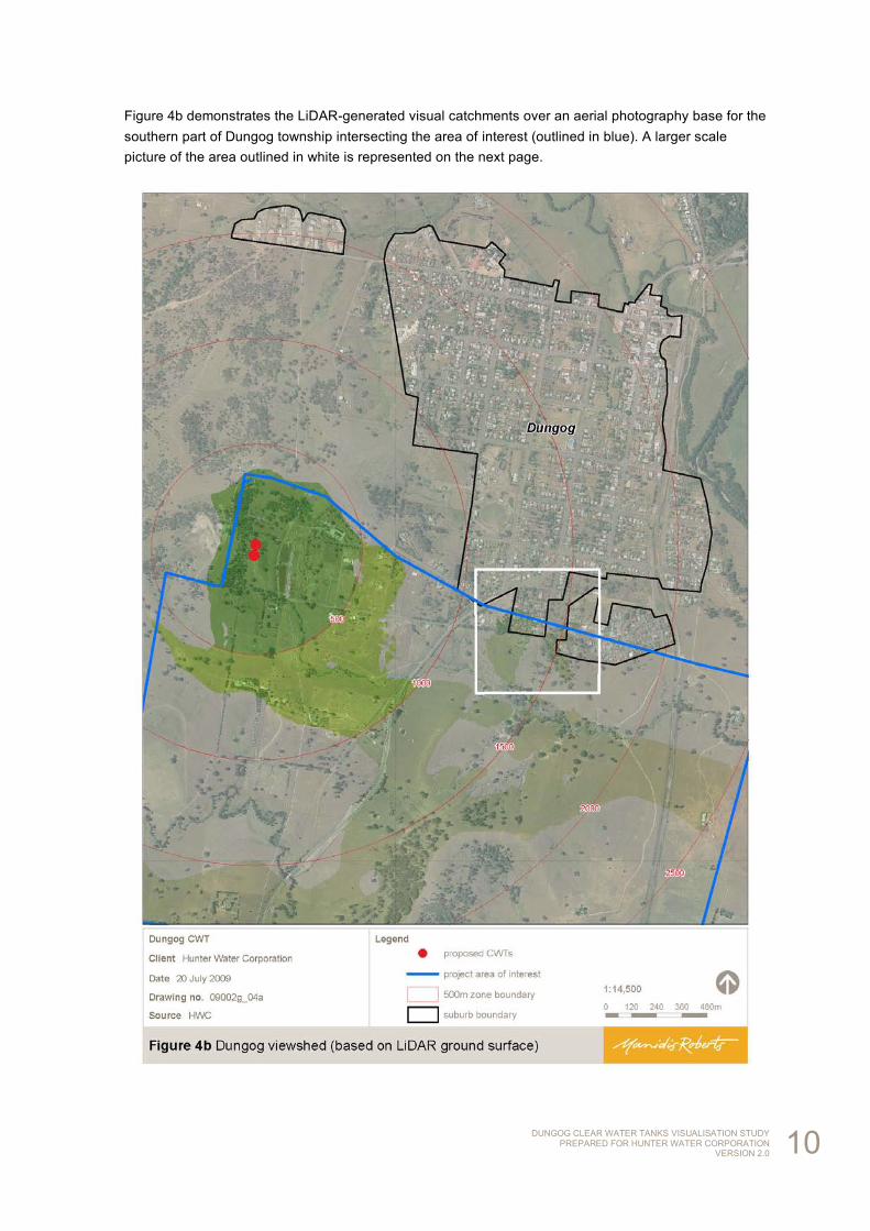
Figure 4b demonstrates the LiDAR-generated visual catchments over an aerial photography base for the southern part of Dungog township intersecting the area of interest (outlined in blue). A larger scale picture of the area outlined in white is represented on the next page.
DUNGOG CLEAR WATER TANKS VISUALISATION STUDY PREPARED FOR HUNTER WATER CORPORATION
VERSION 2.0 11
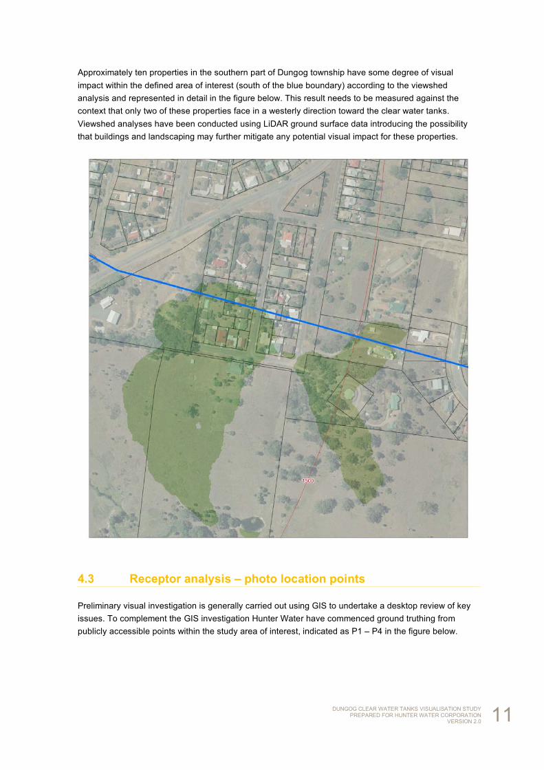
Approximately ten properties in the southern part of Dungog township have some degree of visual impact within the defined area of interest (south of the blue boundary) according to the viewshed analysis and represented in detail in the figure below. This result needs to be measured against the context that only two of these properties face in a westerly direction toward the clear water tanks. Viewshed analyses have been conducted using LiDAR ground surface data introducing the possibility that buildings and landscaping may further mitigate any potential visual impact for these properties.
4.3 Receptor analysis – photo location points
Preliminary visual investigation is generally carried out using GIS to undertake a desktop review of key issues. To complement the GIS investigation Hunter Water have commenced ground truthing from publicly accessible points within the study area of interest, indicated as P1 – P4 in the figure below.
DUNGOG CLEAR WATER TANKS VISUALISATION STUDY PREPARED FOR HUNTER WATER CORPORATION
VERSION 2.0 12
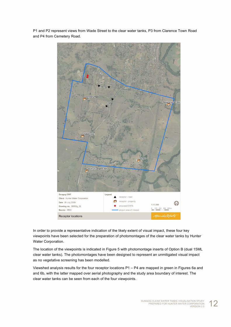
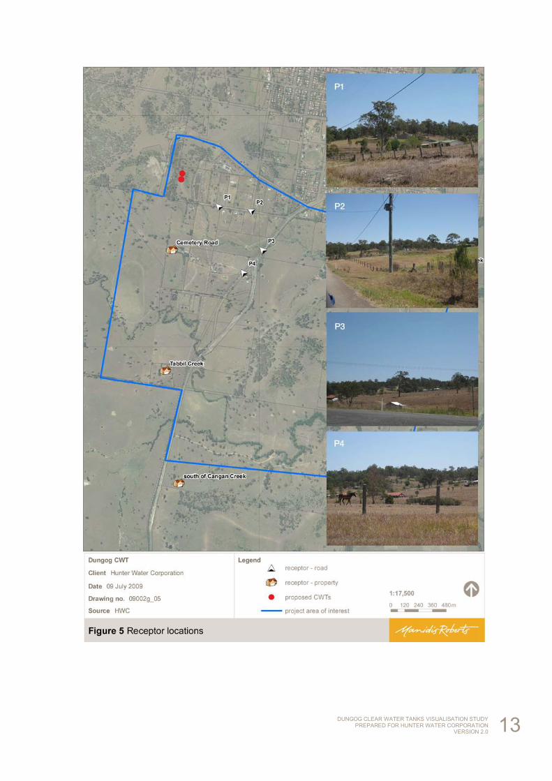
P1 and P2 represent views from Wade Street to the clear water tanks, P3 from Clarence Town Road and P4 from Cemetery Road.
In order to provide a representative indication of the likely extent of visual impact, these four key viewpoints have been selected for the preparation of photomontages of the clear water tanks by Hunter Water Corporation.
The location of the viewpoints is indicated in Figure 5 with photomontage inserts of Option B (dual 15ML clear water tanks). The photomontages have been designed to represent an unmitigated visual impact as no vegetative screening has been modelled.
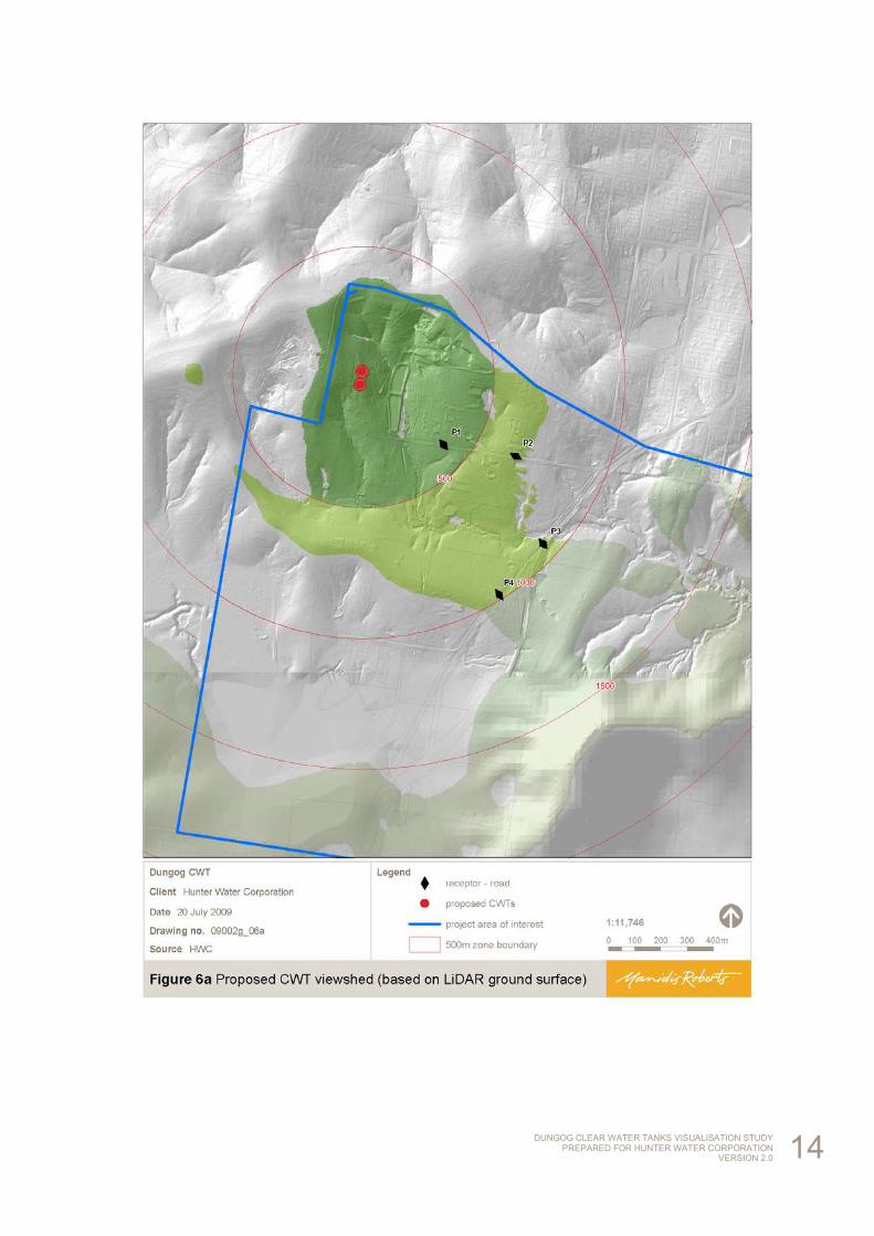
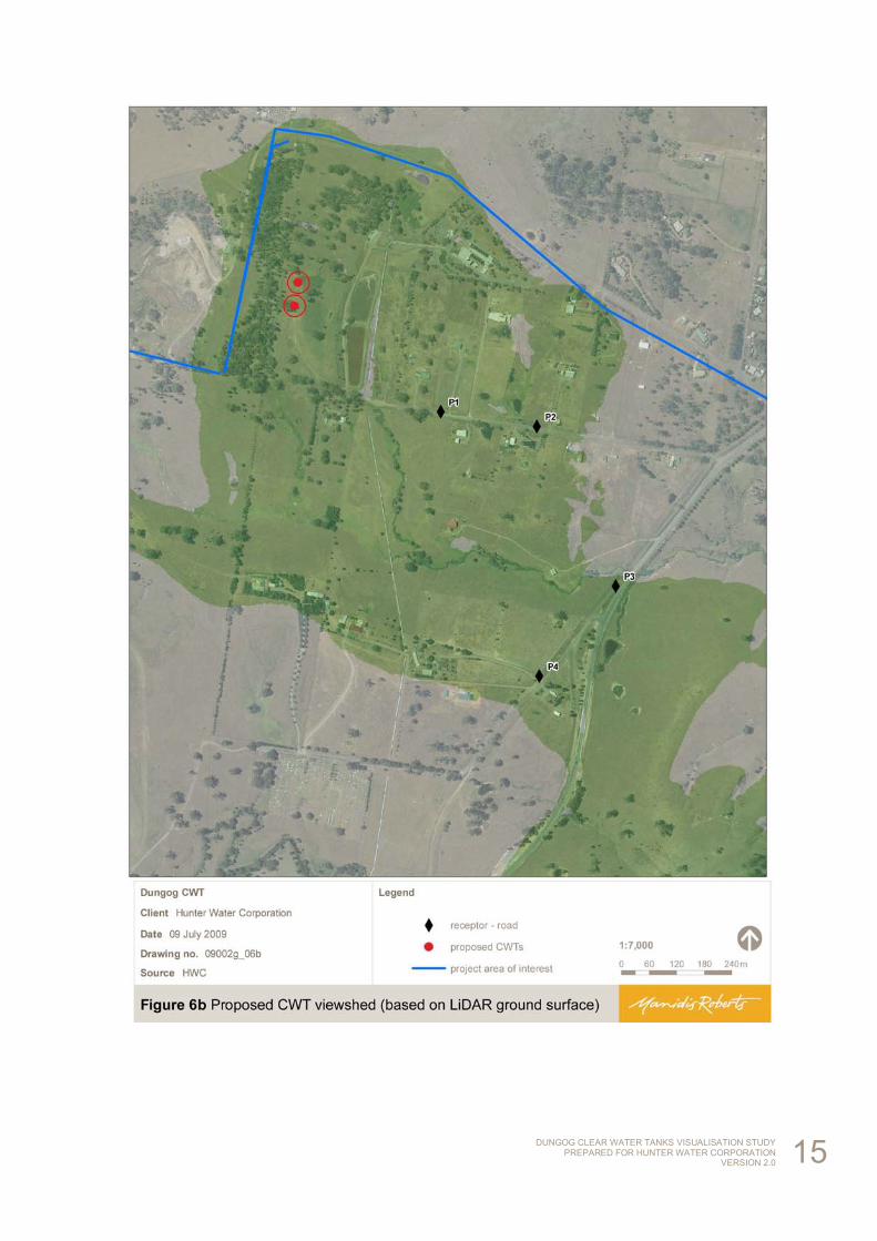
Viewshed analysis results for the four receptor locations P1 – P4 are mapped in green in Figures 6a and and 6b, with the latter mapped over aerial photography and the study area boundary of interest. The clear water tanks can be seen from each of the four viewpoints.
DUNGOG CLEAR WATER TANKS VISUALISATION STUDY PREPARED FOR HUNTER WATER CORPORATION
VERSION 2.0 13
DUNGOG CLEAR WATER TANKS VISUALISATION STUDY PREPARED FOR HUNTER WATER CORPORATION
VERSION 2.0 14
DUNGOG CLEAR WATER TANKS VISUALISATION STUDY PREPARED FOR HUNTER WATER CORPORATION
VERSION 2.0 15
DUNGOG CLEAR WATER TANKS VISUALISATION STUDY PREPARED FOR HUNTER WATER CORPORATION
VERSION 2.0 16
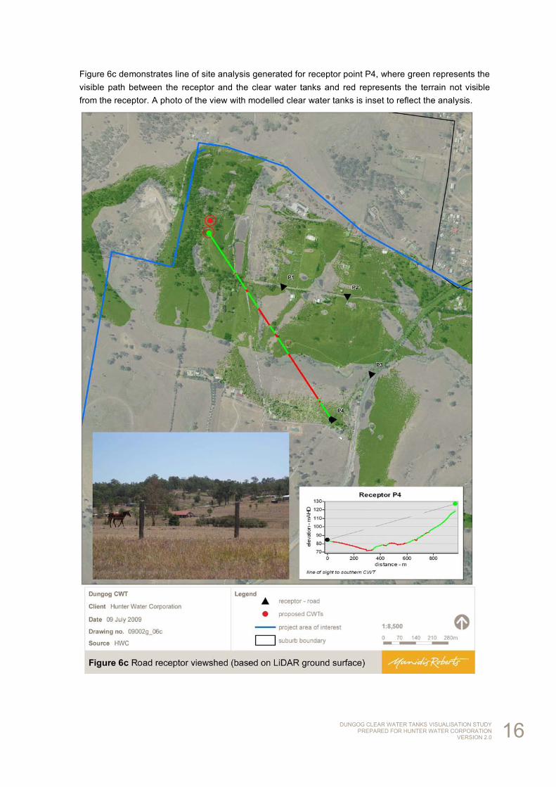
Figure 6c demonstrates line of site analysis generated for receptor point P4, where green represents the visible path between the receptor and the clear water tanks and red represents the terrain not visible from the receptor. A photo of the view with modelled clear water tanks is inset to reflect the analysis.
DUNGOG CLEAR WATER TANKS VISUALISATION STUDY PREPARED FOR HUNTER WATER CORPORATION
VERSION 2.0 17
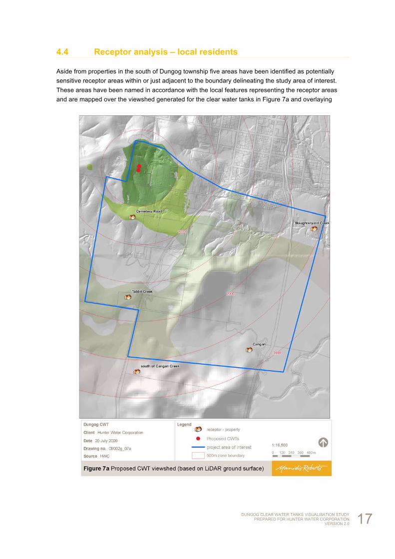
4.4 Receptor analysis – local residents
Aside from properties in the south of Dungog township five areas have been identified as potentially sensitive receptor areas within or just adjacent to the boundary delineating the study area of interest. These areas have been named in accordance with the local features representing the receptor areas and are mapped over the viewshed generated for the clear water tanks in Figure 7a and overlaying
DUNGOG CLEAR WATER TANKS VISUALISATION STUDY PREPARED FOR HUNTER WATER CORPORATION
VERSION 2.0 18
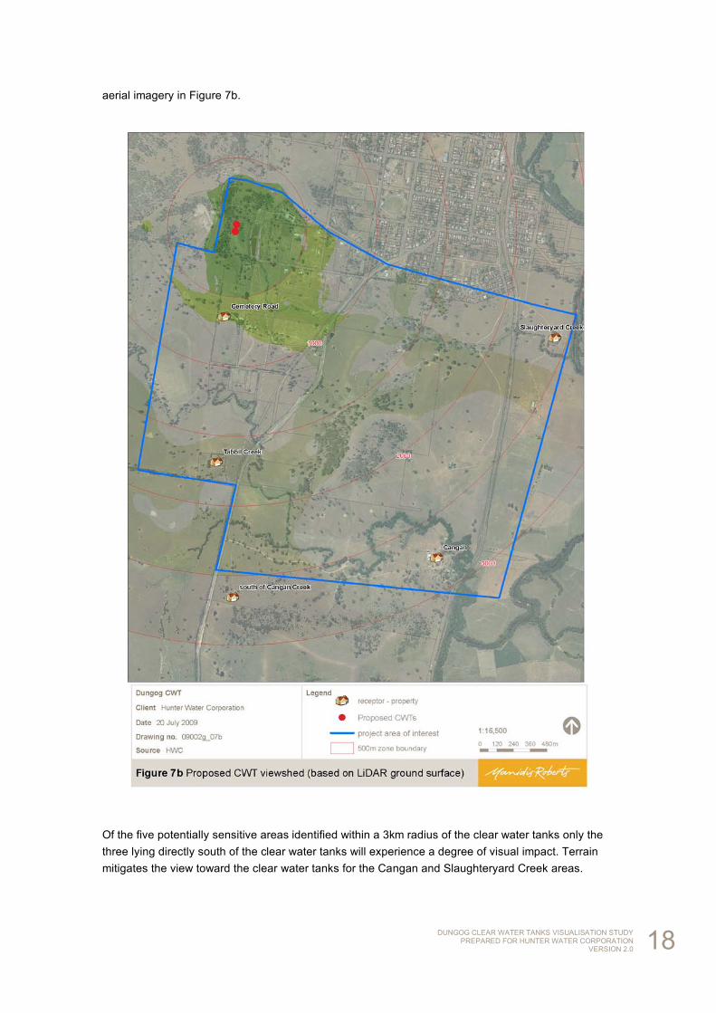
aerial imagery in Figure 7b.
Of the five potentially sensitive areas identified within a 3km radius of the clear water tanks only the three lying directly south of the clear water tanks will experience a degree of visual impact. Terrain mitigates the view toward the clear water tanks for the Cangan and Slaughteryard Creek areas.
DUNGOG CLEAR WATER TANKS VISUALISATION STUDY PREPARED FOR HUNTER WATER CORPORATION
VERSION 2.0 19
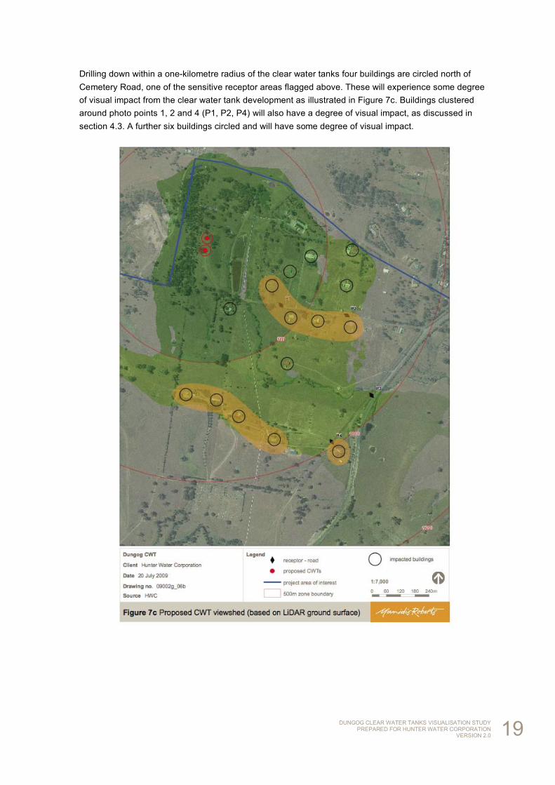
Drilling down within a one-kilometre radius of the clear water tanks four buildings are circled north of Cemetery Road, one of the sensitive receptor areas flagged above. These will experience some degree of visual impact from the clear water tank development as illustrated in Figure 7c. Buildings clustered around photo points 1, 2 and 4 (P1, P2, P4) will also have a degree of visual impact, as discussed in section 4.3. A further six buildings circled and will have some degree of visual impact.
DUNGOG CLEAR WATER TANKS VISUALISATION STUDY PREPARED FOR HUNTER WATER CORPORATION
VERSION 2.0 20
5 Conclusion
The results of a GIS visualisation study of the location of Dungog’s clear water tanks, following concept Option B are summarised in a series of maps presented throughout this report.
Large scale maps demonstrating the LiDAR-generated visual catchments over an aerial photography base have been generated using ground surface data, due to limitations in the density of first-return data.
LiDAR-generated visual catchments for the southern part of Dungog township intersecting the study area of interest represent approximately ten properties as having some degree of visual impact from the clear water tanks. Only two of these potentially impacted properties face in a westerly direction toward the clear water tanks. It should be noted that buildings and landscaping may further mitigate any potential visual impact for these potentially impacted properties, as viewshed analyses have been carried out using ground surface data as stated above.
In order to provide a representative indication of the likely extent of visual impact in the surrounding countryside four key viewpoints have been selected for the preparation of photomontages of the clear water tanks by Hunter Water Corporation: from Wade Street to the clear water tanks, from Clarence Town Road and from Cemetery Road. The photomontages have been designed to represent an unmitigated visual impact as no vegetative screening has been modelled. The clear water tanks can be seen from each of the four viewpoints, as can residents proximal to the viewpoints.
Within a three kilometre radius of the clear water tanks five areas located outside of Dungog township were identified as potentially sensitive receptor areas. Of these only the three lying directly south of the clear water tanks will experience a degree of visual impact as terrain mitigates the view toward the clear water tanks for the other two areas reviewed. Within one kilometre of the clear water tanks this represents a cluster of four buildings north of Cemetery Road, five buildings proximal to photo viewpoints as well as an additional six buildings within 300-600m of the clear water tank development, not all of which appear residential.