
Ductile Iron Society Holds Production Seminar Issue 1.pdf2002 World Conference on ADI The Production...
32
To Promote the production and application of ductile iron castings Issue 1, 2006 Ductile Iron Society Holds Production Seminar FEATURES • Ductile Iron Society Production Seminar PDF ARTICLES • The Production of Austempered Ductile (ADI) • A New Method for Chill and Shrinkage Control in Ladle Treated Ductile Iron • Modeling, Model Verification, and Defect Formation in Iron Castings DEPARTMENTS • News Briefs • Advertisers • Back Issues • DIS Home Page See more photos of the Ductile Iron Seminar Speaker Jim Mullins, Ductile Iron Society General Metallurgy Speaker Fred Linebarger , Miller and Co. Processing & Treatment Methods Speaker Gene Muratore, Rio Tinto Iron & Titanium Gating and Risering Speaker Tim Dorn, Applied Process, Inc. Quality Control View Ductile Iron Related Publications Located in Strongsville, Ohio, USA 15400 Pearl Road, Suite 234; Strongsville,Ohio 44136 Billing Address: 2802 Fisher Road, Columbus, Ohio 43204 Phone (440) 665-3686; Fax (440) 878-0070 email:[email protected]
-
Upload
nguyenthuy -
Category
Documents
-
view
236 -
download
8
Transcript of Ductile Iron Society Holds Production Seminar Issue 1.pdf2002 World Conference on ADI The Production...

The Ductile Iron News
file:///C|/WEBSHARE/062013/magazine/2006_1/index.htm[7/1/2013 2:12:38 PM]
To Promote the production and application of ductile iron castings Issue 1, 2006
Ductile Iron Society HoldsProduction Seminar
FEATURES
• Ductile Iron Society ProductionSeminar
PDF ARTICLES
• The Production of AustemperedDuctile (ADI)
•A New Method for Chill andShrinkage Control in Ladle TreatedDuctile Iron
• Modeling, Model Verification, andDefect Formation in Iron Castings
DEPARTMENTS
• News Briefs
• Advertisers
• Back Issues
• DIS Home Page
See more photos of the Ductile Iron Seminar
Speaker Jim Mullins, Ductile Iron SocietyGeneral Metallurgy
Speaker Fred Linebarger, Miller and Co.Processing & Treatment Methods
Speaker Gene Muratore, Rio Tinto Iron & TitaniumGating and Risering
Speaker Tim Dorn, Applied Process, Inc.Quality Control
View Ductile Iron Related Publications
Located in Strongsville, Ohio, USA15400 Pearl Road, Suite 234; Strongsville,Ohio 44136 Billing Address: 2802 Fisher Road, Columbus, Ohio 43204 Phone (440) 665-3686; Fax (440) 878-0070email:[email protected]
susan
Rectangle

The Ductile Iron News
file:///C|/WEBSHARE/062013/magazine/2006_1/seminarphotos.htm[7/1/2013 2:12:39 PM]
To Promote the production and application of ductile iron castings Issue 1, 2006
FEATURES
• Ductile Iron Society ProductionSeminar
PDF ARTICLES
• The Production of AustemperedDuctile (ADI)
•A New Method for Chill andShrinkage Control in Ladle TreatedDuctile Iron
• Modeling, Model Verification, andDefect Formation in Iron Castings
DEPARTMENTS
• News Briefs
• Advertisers
• Back Issues
• DIS Home Page
Photos from theDuctile Iron Production Seminar
View Ductile Iron Related Publications
Located in Strongsville, Ohio, USA15400 Pearl Road, Suite 234; Strongsville,Ohio 44136 Billing Address: 2802 Fisher Road, Columbus, Ohio 43204 Phone (440) 665-3686; Fax (440) 878-0070email:[email protected]
susan
Rectangle

2002 World Conference on ADI
The Production of Austempered Ductile Iron (ADI)
Kathy L. Hayrynen Applied Process Technologies Division, Livonia, MI
ABSTRACT Austempered Ductile Iron (ADI) results from a specialty heat treatment of ductile cast iron. Strength improvements up to 100% (or more) in combination with excellent toughness can be realized by using this process. Successful production of ADI requires a cooperative effort between the foundry and heat treater. High quality ductile iron is the necessary raw material. The proper heat treatment will then yield the desired mechanical properties. INTRODUCTION After several decades of successful production of Austempered Ductile Iron, the myth that a special type of ductile iron is needed still persists. In fact, the only necessary ingredient for the production of ADI is high quality ductile iron with the appropriate alloy content for hardenability, if needed. This paper will review the austempering heat treat process and the foundry requirements that are necessary for the production of ADI. BACKGROUND The austempering process was first developed in the early 1930’s as a result of work that Bain, et al, was conducting on the isothermal transformation of steel. In the early 1940’s Flinn applied this heat treatment to cast iron, namely gray iron. In 1948 the invention of ductile iron was announced jointly by the British Cast Iron Research Association (BCIRA) and the International Nickel Company (INCO). By the 1950’s, both the material, ductile iron, and the austempering process had been developed. However, the technology to produced ADI on an industrial scale lagged behind. The 1970’s would arrive before highly efficient semi-continuous and batch austempering systems were developed and the process was commercially applied to ductile iron. By the 1990’s, ASTM A897-90 and ASTM A897M-90 Specifications for Austempered Ductile Iron Castings were published in the US while other specifications were developed worldwide. In addition, a new term to
describe the matrix microstructure of ADI as “ausferrite” was introduced. The five Grades of ADI according to ASTM A897/897M are listed in Table 1. Figures 1(a) and (b) show the ausferrite microstructure for Grades 1 and 5 ADI, respectively.
Table 1: ASTM A897/897M Minimum Property
Specifications for ADI Castings
Grade Tensile
Strength (MPa/Ksi)
Yield Strength (MPa/Ksi)
Elong. (%)
Impact Energy (J/ft-lb)
Typical Hardness
(BHN)
1 850 / 125 550 / 80 10 100 / 75 269 – 321
2 1050 / 150 700 / 100 7 80 / 60 302 – 363
3 1200 / 175 850 / 125 4 60 / 45 341 – 444
4 1400 / 200 1100 / 155 1 35 / 25 366 – 477
5 1600 / 230 1300 / 185 N/A N/A 444 - 555
Figure 1a: Photomicrograph of Grade 1 ADI. Specimen was etched with 5% Nital.

2002 World Conference on ADI
Figure 1b: Photomicrograph of Grade 5 ADI. Specimen was etched with 5% Nital.
Figure 3: A schematic of an equilibdiagram of graphitic ductile irosymbols present represent austferrite (α) and graphite (G). TCritical Temperature (UCT) anCritical Temperature (LCT) are labeled.
THE AUSTEMPERING PROCESS Figure 2 contains a schematic of the austempering process. This process includes the following major steps:
1. Heating to the Austenitizing Temperature (A to B)
2. Austenitizing (B to C) 3. Cooling to the Austempering temperature (C
to D) 4. Isothermal heat treatment at the
Austempering temperature (D to E) 5. Cooling to room temperature (E to F)
Figure 2 : A schematic of the Austempering process. Austenitizing Temperature and Time The choice of austenitizing temperature is dependent on the chemical composition of the ductile iron. Figure 3 shows a schematic of an equilibrium diagram for a graphitic ductile iron.
UCT
The austenitizing temperature should be chthe component is in the austenite + grapphase field. Elements like Silicon raise thManganese will lower it. If the temperature is below the UCT or in the sub(γ + α + G), then proeutectoid ferrite will bthe final microstructure, resulting in a lower hardness material. Once the ferrite forms, to eliminate it is to reheat above the UCTshows the microstructure of an austempethat was austenitized below the UCT.
Figure 4: A photomicrograph of ADaustenitized below the UpperTemperature (UCT). The light reFerrite.
LCT
rium phase n. The enite (γ), he Upper
d Lower
osen so that hite (γ + G) e UCT while austenitizing critical range e present in strength and the only way . Figure 4 red material
I that was Critical gions are
2002 World Conference on ADI
The time at the austenitizing temperature is equally as important as the choice of temperature. The ductile iron components should be held for a time sufficient to create an austenite matrix that is saturated with carbon. This time is additionally affected by the alloy content of the ductile iron with heavily alloyed material taking longer to austenitize. Cooling to the Austempering Temperature Cooling from the austenitizing temperature to the austempering temperature (as shown from C to D in Figure 2) must be completed rapidly enough to avoid the formation of pearlite. If pearlite is formed, the strength, elongation and toughness will be reduced. Figure 5 shows a photomicrograph of Grade 2 ADI that contains pearlite.
Figure 5: Pearlite (dark constituent) in Ausferrite. The formation of pearlite can be caused by several things, most notably a lack of quench severity or a low hardenability for the effective section size. It is possible to increase the quench severity of molten salt quench bathes by making water additions. Oil quench equipment is limited to the production of Grade 5 ADI because of the quench temperatures necessary to produce Grades 4 and higher. The alloy content in ADI is necessary for hardenability purposes or the austemperability of the ductile iron. In general, section sizes greater than 19 mm or 0.75 inches require an alloy addition. Typically, a foundry will work closely with the heat treater to determine the optimum chemical composition of the ductile iron to be austempered. Figure 6 shows a schematic of how the alloying elements segregate in ductile iron during solidification.
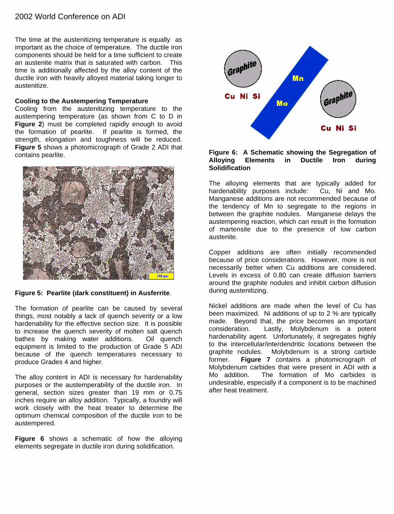
Figure 6: A Schematic showing the Segregation of Alloying Elements in Ductile Iron during Solidification The alloying elements that are typically added for hardenability purposes include: Cu, Ni and Mo. Manganese additions are not recommended because of the tendency of Mn to segregate to the regions in between the graphite nodules. Manganese delays the austempering reaction, which can result in the formation of martensite due to the presence of low carbon austenite. Copper additions are often initially recommended because of price considerations. However, more is not necessarily better when Cu additions are considered. Levels in excess of 0.80 can create diffusion barriers around the graphite nodules and inhibit carbon diffusion during austenitizing. Nickel additions are made when the level of Cu has been maximized. Ni additions of up to 2 % are typically made. Beyond that, the price becomes an important consideration. Lastly, Molybdenum is a potent hardenability agent. Unfortunately, it segregates highly to the intercellular/interdendritic locations between the graphite nodules. Molybdenum is a strong carbide former. Figure 7 contains a photomicrograph of Molybdenum carbides that were present in ADI with a Mo addition. The formation of Mo carbides is undesirable, especially if a component is to be machined after heat treatment.

2002 World Conference on ADI
Figure 7: Molybdenum carbides (white) in ADI. Recommendations for alloying ADI are summarized in Table 2. Table 2: Recommendations for Alloying ADI Recommended Limit
(wt pct) Manganese Max section > 13mm 0.35 max
Max section < 13 mm 0.60 max Copper 0.80 max – only as needed Nickel 2.00 max – only as needed Molybdenum 0.30 max – only as needed Choice of Austempering (Quench) Temperature and Time The choice of austempering temperature and time is dependent on the final properties desired. The typical temperature ranges utilized are 460 – 750°F (or 238 - 399°C). The lower grades (1 and 2) require temperature choices at the upper end of the range while the higher grades are produced at lower quench temperatures. Time at temperature is dependent on the choice of temperature as well as the alloy content. For example, Grade 1 ADI will transform faster than Grade 5 as the quench temperature is approximately 200°F (93°C) higher. The components are held for a sufficient time at temperature for ausferrite to form. Ausferrite consists of ferrite in a high carbon, stabilized austenite. If held for long time periods, the high carbon austenite will eventually undergo a transformation to bainite, the two phase ferrite and carbide (α. + Fe3C). In order for this transformation to occur, longer periods of time are typically needed – much longer than would be economically feasible for the production of ADI.
Once the ausferrite has been produced, the components are cooled to room temperature. The cooling rate will not affect the final microstructure as the carbon content of the austenite is high enough to lower the martensite start temperature to a temperature significantly below room temperature. FOUNDRY CONSIDERATIONS FOR THE PRODUCTION OF ADI The austempering process creates a product that is stronger than conventional grades of ductile iron. As a result, it is more sensitive to any defects that could be present in the base ductile iron. Austempering is NOT a cure for poor quality iron. Rather, the effects of the slightest defects on the mechanical properties of ductile iron become magnified as a result of austempering. Thus, the toughness of an ADI component can be severely compromised by the presence of non-metallic inclusions, carbides, shrink and dross even if their levels were acceptable for conventional ductile iron. There is no “one” optimum recipe for ductile iron that is to be austempered. However, high quality is imperative in all cases. Nodule Count and Nodularity The recommended minimums for nodule count and nodularity for ductile iron to be austempered are as follows: Nodule Count 100/mm2 ( with a uniform distribution) Nodularity 85% Nodule count is especially important when alloy additions are made. Low nodule counts lead to larger spacing between the graphite nodules and larger regions of segregation (Note Figure 6.). In the worst case scenario, these regions can become so heavily segregated that they do not fully transform during austempering, resulting in the formation of low carbon austenite or even martensite. Figure 8 shows regions of segregation that did not transform during austempering. Higher nodule counts will break up the segregated regions shown in Figure 8.

2002 World Conference on ADI
Figure 8: Segregated regions (white) with a high Mn content in ADI. Casting Quality Castings to be austempered should be free of non-metallic inclusions, carbides, shrink and porosity. In order to achieve the property minimums in Table 1, the following levels should be maintained. Carbides + Nonmetallic inclusions - maximum 0.5% Porosity and/or Microshrinkage – maximum 1% Carbon Equivalent The Carbon Equivalent (CE = %C + 1/3 %Si) should be controlled to produce sound castings. General Guidelines are provided in Table 3. Table 3: Carbon Equivalent Guidelines for the Production of ADI
Section Size CE Range 0 – 0.5 inches ( 0 – 13 mm) 4.4 – 4.6 0.5 – 2 inches (13 – 51 mm) 4.3 – 4.6 Over 2 inches (51 mm) 4.3 – 4.5
Chemical Composition The chemical composition ranges for a component should initially be established between the foundry and the heat treater. The amount of alloy (if needed) will be a function of the alloy in the foundry’s base metal, the part configuration (section size and shape) and the austempering equipment that is used. Suggested chemistry targets along with typical control ranges are listed in Table 4.
Table 4: Suggested Targets and Typical Control Ranges for the Production of ADI
Element Suggested Target
Typical Control Range
Carbon – C 3.6% ± 0.20% Silicon – Si 2.5% ± 0.20% Magnesium – Mg (%S x 0.76)+0.025% ± 0.005% Manganese – Mn Max section > 13 mm Max section < 13 mm
0.35% maximum 0.60% maximum
± 0.05%
Copper – Cu 0.80% maximum (only as needed)
± 0.05%
Nickel – Ni 2.00% maximum (only as needed)
± 0.10%
Molybdenum - Mo 0.30% maximum (only as needed)
± 0.03%
Tin - Sn 0.02% maximum (only as needed)
±0.003%
Antimony – Sb 0.002% maximum (only as needed)
±0.0003%
Phosphorus – P 0.04% maximum Sulfur – S 0.02% maximum Oxygen – O 50 ppm maximum Chromium – Cr 0.10% maximum Titanium – Ti 0.040% maximum Vanadium – V 0.10% maximum Aluminum – Al 0.050% maximum Arsenic – As 0.020% maximum Bismuth – Bi 0.002% maximum Boron – B 0.002% maximum Cadmium – Cd 0.005 maximum Lead – Pb 0.002% maximum Selenium – Se 0.030% maximum Tellurium – Te 0.020% maximum Once chemical composition ranges have been established between the foundry and the heat treater, it is important for the foundry to produce ductile iron within the established ranges. Wide variations in chemical composition can lead to variations in the pearlite/ferrite ratio in the as-cast ductile iron as well as a need to adjust the heat treatment parameters. The response or growth during austempering is a function of the prior microstructure and the austempering temperature. Figure 9 shows the linear dimensional change as a function of austempering temperature for ADI with prior microstructures of ferrite, pearlite and a ferrite/pearlite mix.
2002 World Conference on ADI
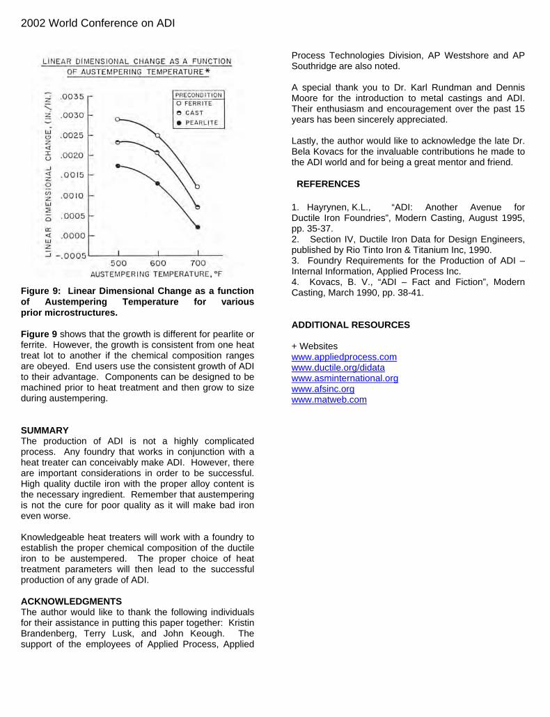
Figure 9: Linear Dimensional Change as a function of Austempering Temperature for various prior microstructures.
4. Kovacs, B. V., “ADI – Fact and Fiction”, Modern Casting, March 1990, pp. 38-41.
Figure 9 shows that the growth is different for pearlite or ferrite. However, the growth is consistent from one heat treat lot to another if the chemical composition ranges are obeyed. End users use the consistent growth of ADI to their advantage. Components can be designed to be machined prior to heat treatment and then grow to size during austempering. SUMMARY The production of ADI is not a highly complicated process. Any foundry that works in conjunction with a heat treater can conceivably make ADI. However, there are important considerations in order to be successful. High quality ductile iron with the proper alloy content is the necessary ingredient. Remember that austempering is not the cure for poor quality as it will make bad iron even worse. Knowledgeable heat treaters will work with a foundry to establish the proper chemical composition of the ductile iron to be austempered. The proper choice of heat treatment parameters will then lead to the successful production of any grade of ADI. ACKNOWLEDGMENTS The author would like to thank the following individuals for their assistance in putting this paper together: Kristin Brandenberg, Terry Lusk, and John Keough. The support of the employees of Applied Process, Applied
Process Technologies Division, AP Westshore and AP Southridge are also noted. A special thank you to Dr. Karl Rundman and Dennis Moore for the introduction to metal castings and ADI. Their enthusiasm and encouragement over the past 15 years has been sincerely appreciated. Lastly, the author would like to acknowledge the late Dr. Bela Kovacs for the invaluable contributions he made to the ADI world and for being a great mentor and friend. REFERENCES 1. Hayrynen, K.L., “ADI: Another Avenue for Ductile Iron Foundries”, Modern Casting, August 1995, pp. 35-37. 2. Section IV, Ductile Iron Data for Design Engineers, published by Rio Tinto Iron & Titanium Inc, 1990. 3. Foundry Requirements for the Production of ADI – Internal Information, Applied Process Inc.
ADDITIONAL RESOURCES + Websites www.appliedprocess.com www.ductile.org/didata www.asminternational.org www.afsinc.org www.matweb.com

2003 Keith Millis Symposium on Ductile Cast Iron
A New Method for Chill and Shrinkage Control in Ladle Treated Ductile Iron
T.Skaland
Elkem Foundry Products, Kristiansand, Norway
ABSTRACT The present paper is undertaken with the objective of describing a new method for treating ductile cast iron in a ladle process, where the main objective is to minimize formation of eutectic carbides and shrinkage porosity during solidification. The suppression of carbide formation is associated with the nucleating properties of the nodularizer and inoculant alloys. By nucleating properties it is understood the number and potency of nuclei formed by an alloy addition. The nodularizer and inoculant additions also influence ductile iron solidification shrinkage. Some alloys may give good protection against shrinkage while others tend to promote more shrinkage. The use of various rare earth elements is found to have a pronounced impact on these conditions. It has been discovered that the use of pure lanthanum as the primary rare earth source in the magnesium ferrosilicon nodularizer surprisingly further improves the performance of the ductile iron ladle treatment method compared to similar methods using cerium or misch metal bearing nodularizers. The nucleating properties are substantially improved and the risk for chill and shrinkage formation in the sandwich or tundish ladle treated ductile iron is then minimized. The paper describes this new ladle treatment concept in detail, and gives examples from successful testing of the new nodularizing technology and how it simultaneously affects and minimizes critical ductile iron chill and shrinkage tendencies. INTRODUCTION The scope of the present work is to study the effects of lanthanum and cerium bearing MgFeSi alloys used in ladle treatment of ductile iron on the microstructure evolution, graphite morphology and solidification shrinkage in ductile irons produced under controlled laboratory conditions.
BACKGROUND Previous investigations have shown that rare earth metals (REM) such as cerium, lanthanum, praseodymium and neodymium can either have a beneficial or a detrimental effect on the microstructure and properties of ductile iron, depending on the casting conditions. For example, small additions of REM are frequently used to restore the graphite nodule count and nodularity in ductile irons containing subversive elements such as Sb, Pb, Ti etc.1-3 On the other hand, rare earths in excessive concentrations may lead to problems with chill formation in thin cast sections and chunky graphite in heavier sections, with subsequent degradation in the mechanical properties.4-6
Several investigators have reported an optimum level of REM with respect to a high nodule count and reduced carbide formation. However, the optimum rare earth content varies significantly according to different investigators. For example, Lalich7 concluded that the optimum cerium level is about 0.006 to 0.010 wt% for low cerium rare earth’s, and about 0.015 to 0.020 wt% for high cerium rare earth’s, while Kanetkar et al8 found a maximum nodule count at a cerium concentration of 0.032 wt%. The lowest values as reported by Lalich7 are close to the residual level of cerium in commercial irons, and seem therefore difficult to control in practice. Kanetkar et al8 also reported that separate additions of lanthanum, praseodymium and neodymium produce an optimum nodule count at a certain concentration level of each element. The residual contents required for an optimum nodule count were as follows: 0.018% for lanthanum, 0.007-0.010% for praseodymium, and 0.017% for neodymium. Similar values for cerium and lanthanum were also reported by Onsøien et al9, i.e. 0.035% cerium and 0.017% lanthanum. Graphite type, size and shape formed during ductile iron solidification, as well as the amount of graphite versus iron carbide, can be controlled with certain additives that promote the formation of graphite during solidification of cast iron. These additives are referred to as nodularizers and inoculants and their addition to the cast iron as nodularizing and inoculation. In casting iron products from liquid iron, there will always be a risk for the formation of iron carbides in thin sections of castings.

2003 Keith Millis Symposium on Ductile Cast Iron
The formation of iron carbide is brought about by the rapid cooling of the thin sections as compared to the slower cooling of the thicker sections of the casting. The formation of iron carbide in a cast iron is referred to as “chill” and is quantified by measuring “chill depth”. The power of a nodularizer or inoculant to prevent chill and reduce chill depth is a convenient way to measure and compare the individual power of different nodularizers and inoculants. Since the exact chemistry and mechanism of nucleation and why nodularizers and inoculants function as they do is not completely understood, a great deal of research goes into providing the industry with new and improved alloys. The suppression of carbide formation is associated with the nucleating properties of the nodularizer and inoculant. By nucleating properties it is understood the number of nuclei formed by an alloy addition. A high number of nuclei formed improves the effectiveness of the carbide suppression. Further a high nucleation rate may also give better resistance to fading effects during prolonged holding time of the molten iron after nodularizing and inoculation. The nodularizer and inoculant alloys also affect ductile iron solidification shrinkage. Some alloys may give good protection against shrinkage while others tend to promote more shrinkage. The use of various rare earth elements may have a pronounced impact on this condition. For nodularizer alloys it is also important that composition of the alloy is such that a minimum of shrinkage occurs during solidification of the iron. The nodularizing process is carried out in two basically different ways. In the so-called “ladle treatment method”, the nodularizer alloy is placed in the bottom of the ladle whereafter liquid cast iron is poured into the ladle on the top of the nodularizer alloy. Depending on how the nodularizer alloy is placed in the ladle, the ladle treatment method is known as overpour, sandwich, or tundish cover treatment methods. Inoculation is normally carried out after the nodularizing process is done, by adding inoculant to the metal stream during transfer of the cast iron to a pouring vessel or to a mould. In the so-called “in-the-mould” method, the nodularizing treatment is taking place inside the mould cavity itself. The in-the-mould nodularizing method is thus significantly different from the ladle treatment nodularizing method. According to Dunks10, the addition of pure lanthanum with magnesium ferrosilicon alloy has proven successful for the purpose of minimizing chill and shrinkage in ductile iron when using the in-the-mould nodularizing method. In the in-the-mould treatment method, the
magnesium ferrosilicon alloy acts both as a nodularizer and inoculant simultaneously integrated into the gating system of the mould. For magnesium treatment of cast iron in the ladle treatment nodularizing method, such integrated or combined nodularizing and inoculation is not yet known. MATERIALS AND EXPERIMENTAL WORK Ductile iron heats were produced in an induction furnace from a charge based on 50 wt% steel, 20 wt% iron returns and 30 wt% pig iron. Carbon and silicon were adjusted using graphite recarburizer and ferrosilicon. Prior to tapping into the treatment ladle, 1.5 wt% magnesium ferrosilicon alloy was placed into the ladle and covered by 0.5 kg steel punchings, i.e. nodularizing according to the sandwich treatment method. Figure 1 shows a schematic representation of the type of tundish/sandwich treatment ladles used. Two minutes after treatment the iron was transferred into the pouring ladle. No post-inoculant has been added after the nodularizing treatment, thus the experimental irons are cast into the sand moulds in un-inoculated condition. This is done to only reveal the characteristic effects of the individual nodularizing alloys. Coin shaped samples for chemical analysis were extracted from the melt, and the ductile iron was then cast into sand moulds to produce a 20 mm thick plate, a 5 mm thin plate, a chill wedge sample and a cross bar sample for shrinkage evaluation. The target final composition was 3.7%C, 2.4%Si, 0.4%Mn, 0.010%S and 0.040%Mg. Table 1 shows the chemical composition of the different magnesium ferrosilicon alloys used in this experimental work. The alloys are based on 45% FeSi with about 6%Mg, 1%Ca, and 0.9%Al. The rare earth content is varied according to Table 1. Pure lanthanum at 0.5% and 1.0% as well as pure cerium at 0.5% and 1.0% are compared to a RE-free reference alloy and a conventional 1.0%RE bearing alloy where the rare earth is present as 50% cerium bearing Misch metal.

2003 Keith Millis Symposium on Ductile Cast Iron
Sandwich Tundish Cover
Treatment alloy
Treatment ladle
Tundish cover
Molten iron
Ladle
Cover
Treatment alloy
Pour-over
Molten iron
Ladle
Treatment alloy
Figure 1: Examples of overpour, sandwich and tundish cover ladles.
Table 1: Chemical composition of magnesium ferrosilicon nodularizer alloys.
Nodularizer %Si %Mg %Ca %Al %RE %Ce %La
RE-free 45.8 6.1 1.0 0.9 0.0 0.0 0.0
0.5% La 45.0 5.8 1.0 0.9 0.5 0.0 0.5
1.0% La 45.5 6.0 1.0 0.9 1.0 0.0 1.0
0.5% Ce 45.6 6.1 1.0 0.9 0.5 0.5 0.0
1.0% Ce 45.4 6.1 0.9 0.9 1.0 1.0 0.0
1.0% MM 45.0 5.9 1.1 0.8 1.0 0.5 0.25 %RE is the total rare earth content (sum of Ce, La, Pr, and Nd). Balance iron. Thermal analyses were performed for each heat using samples extracted from the melt in the pouring ladle. Liquid metal was poured into a standard Quick-cup and the cooling curve recorded using the Novacast ATAS Verifier 4.0 software for analysing characteristic temperature data. The following parameters were extracted from ATAS for comparison: low eutectic temperature (TElow), high eutectic temperature (TEhigh), final solidification temperature (TS), recalesence (R), graphite factor 1 (GRF1), and graphite factor 2 (GRF2). Chemical analysis of chilled coin shaped specimen was performed using XRF. The coin samples were also used for determination of carbon and sulphur contents by Leco, and magnesium concentration by AAS. Samples were taken from all treated pouring ladles. Samples for metallographic examination were extracted from a cross section cut through the centre of the 5 mm and 20 mm plates. The metallographic samples were prepared according to standard metallographic techniques, i.e. polished to a 1 µm diamond spray finish for characterisation of the graphite. The graphite phase was characterized using an image analysis system (ImagePro Plus). For analysis of graphite particle parameters, only the graphite nodules larger than 5 µm
were measured. The following data was recorded: nodule count, area fraction of graphite, nodule diameter, nodule shape factor, and nodularity, where nodularity is the percent of graphite nodules with a shape factor better than 0.65. The polished samples were then etched in 2% Nital for automatic image analysis quantification of the microstructure constituents i.e. ferrite, pearlite and carbides. Chill was evaluated by means of a standard chill wedge sample. Two features were measured, L1 which is the maximum distance, in mm, at which chill is formed in the whole cross section of the chill wedge sample (clear chill), and L2 which is the maximum distance at which carbides are found (total chill). The crossbar specimens were cut horizontally in a section through the center of the cross to evaluate shrinkage porosity. The specimens were ground and polished to a 1 µm diamond spray finish, and porosity measured in a reference area of 12 by 12 mm manually positioned at the center of the cross. An image analysis system (ImagePro Plus) was used to quantify the area fraction of porosity in the section relative to the reference area.
RESULTS AND DISCUSSION Chemical Analysis Results from chemical analyses of the different heats are summarized in Table 2. It is clear that the targeted final composition of 3.7%C, 2.4%Si, 0.4%Mn, 0.010%S and 0.040%Mg is quite well obtained for all experimental heats. Variations in cerium and lanthanum analyses are projecting the different input of these two elements from the individual MgFeSi alloys applied. Cerium ranges from residual level up to 0.016%, while lanthanum ranges from residual up to 0.015% in the experimental series. Microstructure Results from metallographic evaluation of graphite structures are shown in Table 3. Microstructures of the test castings are shown in Figures 2 and 3, for the 5 and 20 mm plate sections, respectively. Figure 4 shows histograms for nodule count, nodularity, average nodule diameter, as well as pearlite content for the 20 mm section plate samples.

2003 Keith Millis Symposium on Ductile Cast Iron
Table 2: Chemical composition of the produced experimental ductile iron castings. Nodularizer %C %Si %Mn %P %S %Mg %Ce %La
RE-free 3.73 2.51 0.46 0.027 0.009 0.046 <0.004 <0.004 0.5% La 3.75 2.28 0.43 0.020 0.008 0.043 <0.004 0.008 1.0 % La 3.73 2.25 0.42 0.024 0.010 0.040 <0.004 0.015 0.5% Ce 3.70 2.38 0.45 0.020 0.007 0.041 0.010 0.005 1.0 % Ce 3.71 2.35 0.45 0.021 0.008 0.045 0.016 0.007
1.0% Misch 3.74 2.37 0.45 0.021 0.008 0.047 0.010 0.005
Table 3: Characteristic graphite data for cast 5 and 20 mm plate sample sections. 5 mm plates 20 mm plates
Nodularizer alloy
Nodule count
(N/mm2)
Nodularity (%)
Average diameter
(µm)
Average Shape Factor
Nodule count
(N/mm2)
Nodularity (%)
Average diameter
(µm)
Average Shape factor
RE-free 110 81 9.3 0.75 112 42 20.2 0.50
0.5%La 595 93 13.4 0.88 224 78 17.5 0.74
1.0%La 488 93 13.2 0.88 188 69 19.1 0.67
0.5%Ce 164 73 13.1 0.70 148 55 24.3 0.59
1.0%Ce 177 75 15.4 0.72 149 60 23.1 0.64
1.0%MM 418 93 14.8 0.86 178 69 20.8 0.67
(a) (b) (c)
(d) (e) (f)
Figure 2: Microstructure in 5 mm plate castings for the different nodularizer alloys. (a) RE-free, (b) 0.5%La, (c) 1.0%La, (d) 0.5%Ce, (e) 1.0%Ce, (f) 1.0%MM.
2003 Keith Millis Symposium on Ductile Cast Iron
(a) (b) (c)
(d) (e) (f)
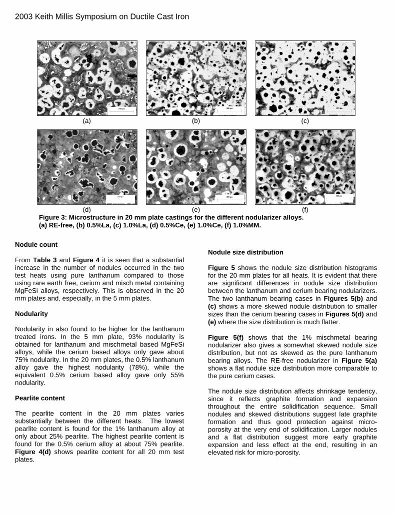
Figure 3: Microstructure in 20 mm plate castings for the different nodularizer alloys. (a) RE-free, (b) 0.5%La, (c) 1.0%La, (d) 0.5%Ce, (e) 1.0%Ce, (f) 1.0%MM.
Nodule count From Table 3 and Figure 4 it is seen that a substantial increase in the number of nodules occurred in the two test heats using pure lanthanum compared to those using rare earth free, cerium and misch metal containing MgFeSi alloys, respectively. This is observed in the 20 mm plates and, especially, in the 5 mm plates. Nodularity Nodularity in also found to be higher for the lanthanum treated irons. In the 5 mm plate, 93% nodularity is obtained for lanthanum and mischmetal based MgFeSi alloys, while the cerium based alloys only gave about 75% nodularity. In the 20 mm plates, the 0.5% lanthanum alloy gave the highest nodularity (78%), while the equivalent 0.5% cerium based alloy gave only 55% nodularity. Pearlite content The pearlite content in the 20 mm plates varies substantially between the different heats. The lowest pearlite content is found for the 1% lanthanum alloy at only about 25% pearlite. The highest pearlite content is found for the 0.5% cerium alloy at about 75% pearlite. Figure 4(d) shows pearlite content for all 20 mm test plates.
Nodule size distribution Figure 5 shows the nodule size distribution histograms for the 20 mm plates for all heats. It is evident that there are significant differences in nodule size distribution between the lanthanum and cerium bearing nodularizers. The two lanthanum bearing cases in Figures 5(b) and (c) shows a more skewed nodule distribution to smaller sizes than the cerium bearing cases in Figures 5(d) and (e) where the size distribution is much flatter. Figure 5(f) shows that the 1% mischmetal bearing nodularizer also gives a somewhat skewed nodule size distribution, but not as skewed as the pure lanthanum bearing alloys. The RE-free nodularizer in Figure 5(a) shows a flat nodule size distribution more comparable to the pure cerium cases. The nodule size distribution affects shrinkage tendency, since it reflects graphite formation and expansion throughout the entire solidification sequence. Small nodules and skewed distributions suggest late graphite formation and thus good protection against micro-porosity at the very end of solidification. Larger nodules and a flat distribution suggest more early graphite expansion and less effect at the end, resulting in an elevated risk for micro-porosity.

2003 Keith Millis Symposium on Ductile Cast Iron
Chilling tendency From Figures 2(b) and (c) it is seen that the lanthanum containing magnesium ferrosilicon alloys strongly reduces and nearly eliminates chill carbides in the 5 mm plates, and that no chill can be found in the 20 mm plates as shown in Figures 3(b) and (c). The pure cerium bearing alloys, Figures 2(d) and (e), resulted in substantial chilling in the 5 mm plate, while the 1% mischmetal containing alloy, Figure 2(f), only gave moderate carbide formation in this plate section. The RE-free nodularizer,n Figure 2(a), resulted in a fully white 5 mm casting section and a mixed carbide-graphite structure in the 20 mm plate section shown in Figure 3(a). Results from measurements of clear chill width in the cast wedge samples are reported in Figure 7(b). This histogram shows that the RE-free nodularizer and the two pure cerium bearing nodularizers gave fully white wedge samples all the way to the top of the wedge (50 mm). The lanthanum bearing nodularizers gave the
smallest chill at only about 11 to 12 mm, while the mischmetal bearing alloy resulted in about 14 mm chill in the wedge. Shrinkage porosity Table 4 and Figures 6(b) and (c) show that shrinkage porosity is totally eliminated when using the pure lanthanum bearing MgFeSi alloys. Both pure cerium bearing alloys in, Figures 6(d) and (e), show indications of scattered micro-porosity in the structure with about 2% pore volume measured in both cases. The 1% mischmetal containing alloy in Figure 6(f) shows a large shrinkage cavity, resulting from primary shrinkage effects during solidification. Figure 6(a) shows substantial scattered micro-porosity found in the RE-free nodularizer sample. Figure 7(d) shows a histogram representing relative shrinkage volumes for all samples tested.
Nodule count
0
100
200
300
400
500
600
700
RE-free 0.5% La 1.0% La 0.5% Ce 1.0% Ce 1.0% MM
5 mm20 mm
(a)
Nodularity
0102030405060708090
100
RE-free 0.5% La 1.0% La 0.5% Ce 1.0% Ce 1.0% MM
5 mm20 mm
(b)
Average Nodule
0
5
10
15
20
25
30
RE-free 0.5% La 1.0% La 0.5% Ce 1.0% Ce 1.0% MM
5 mm20 mm
(c)
Pearlite 20 mm Plate
0
10
20
30
40
50
60
70
80
RE-free 0.5% La 1.0% La 0.5% Ce 1.0% Ce 1.0% MM
(d) Figure 4: Microstructure parameters as a function of nodularizer alloy for the 5 and 20 mm plates. (a) nodule count, (b) nodularity, (c) average nodule diameter, (e) pearlite content (20 mm plate only).

2003 Keith Millis Symposium on Ductile Cast Iron
0%5%
10%15%20%25%30%35%40%
5-10
10-1
5
15-2
0
20-2
5
25-3
0
30-3
5
35-4
0
40-4
5
45-5
0
>50
Diameter(µm)
(a)
0%5%
10%15%20%25%30%35%40%
5-10
10-1
5
15-2
0
20-2
5
25-3
0
30-3
5
35-4
0
40-4
5
45-5
0
>50
Diameter(µm)
(b)
0%
5%
10%
15%
20%
25%
30%
5-10
10-1
5
15-2
0
20-2
5
25-3
0
30-3
5
35-4
0
40-4
5
45-5
0
>50
Diameter(µm)
(c)
0%5%
10%15%20%25%30%35%
5-10
10-1
5
15-2
0
20-2
5
25-3
0
30-3
5
35-4
0
40-4
5
45-5
0
>50
Diameter(µm)
(d)
0%5%
10%15%20%25%30%35%40%
5-10
10-1
5
15-2
0
20-2
5
25-3
0
30-3
5
35-4
0
40-4
5
45-5
0
>50
Diameter(µm)
(e)
0%
5%
10%
15%
20%
25%
5-10
10-1
5
15-2
0
20-2
5
25-3
0
30-3
5
35-4
0
40-4
5
45-5
0
>50
Diameter(µm)
(f)
Figure 5: Nodule size distribution for the different nodularizer alloys. (a) RE-free, (b) 0.5%La, (c) 1.0%La, (d) 0.5%Ce, (e) 1.0%Ce, (f) 1.0%MM.
Table 4: Relative shrinkage porosity area in crossbar castings.
Nodularizer Area % pores
RE-free 8.3
0.5% La 0.0
1.0% La 0.0
0.5% Ce 2.3
1.0% Ce 2.0
1.0% Misch 38.2
Because of the low chill and shrinkage formation tendencies, especially for the 0.5% lanthanum containing magnesium ferrosilicon alloy, the need for a subsequent addition of post inoculant material is minimized or may even be eliminated. Thus, the lanthanum-bearing MgFeSi alloy ladle treatment process represents a unique new nodularizing method that will be cost effective also in the sense that a minimum requirement for inoculation performance is needed. Thermal analysis data Thermal analysis performed on each heat using the ATAS Verifier 4.0 software shows some important differences between the cooling curves of the individual nodularizers tested. Figure 7(a) shows the characteristic temperatures from ATAS; TElow, TEhigh, and TS, representing low
eutectic, high eutectic, and end of solidification temperatures, respectively. It is seen from Figure 7(a) that the highest temperatures are recorded for the 0.5% lanthanum bearing alloy, suggesting the highest resistance towards chill and shrinkage formation. The lowest TS temperatures are recorded for the cerium bearing alloys as well as the RE-free alloy. Low TS is an indication of high micro-shrinkage formation tendency. These observations from thermal analysis temperature measurements correspond well with the actual measurements of chill and shrinkage in the present casting samples, see Figures 7(b) and (d). Figure 7(c) shows a histogram for the characteristic graphite factors 1 and 2 (GRF1 and GRF2) from the ATAS thermal analysis. These factors give important information about shrinkage tendency. A large GRF1 and a small GRF2 are desired for minimum shrinkage formation tendency. It is found that the two pure lanthanum-bearing alloys give the highest GRF1 values at about 95 to 100, and the lowest GRF2 values at about 30-35. The inverse situation is found for the pure cerium bearing alloys. These observations from the graphite factor measurements correspond well with the actual measurements of shrinkage in the present casting samples, see Figure 7(d).

2003 Keith Millis Symposium on Ductile Cast Iron
(a)
(b)
(c)
(d)
(e)
(f)
Figure 6: Shrinkage porosity in section cut through the crossbar casting for different nodularizer alloys. (a) RE-free, (b) 0.5%La, (c) 1.0%La, (d) 0.5%Ce, (e) 1.0%Ce, (f) 1.0%MM.
TE low, TE high, and TS
1080
1090
1100
1110
1120
1130
1140
1150
1160
RE-free 0.5% La 1.0% La 0.5% Ce 1.0% Ce 1.0% MM
TE lowTE highTS
(a)
Chill L1
05
101520253035404550
RE-free 0.5% La 1.0% La 0.5% Ce 1.0% Ce 1.0% MM
(b)
GRF1 and GRF2
0
20
40
60
80
100
120
140
160
RE-free 0.5% La 1.0% La 0.5% Ce 1.0% Ce 1.0% MM
GRF1GRF2
(c)
Shrinkage Porosity
05
1015202530354045
RE-free 0.5% La 1.0% La 0.5% Ce 1.0% Ce 1.0% MM
(d) Figure 7: Characteristic ATAS thermal analysis data (TElow, TEhigh, TS, GRF1, GRF2), chill wedge carbides, and relative shrinkage porosity for the experimental castings.
2003 Keith Millis Symposium on Ductile Cast Iron
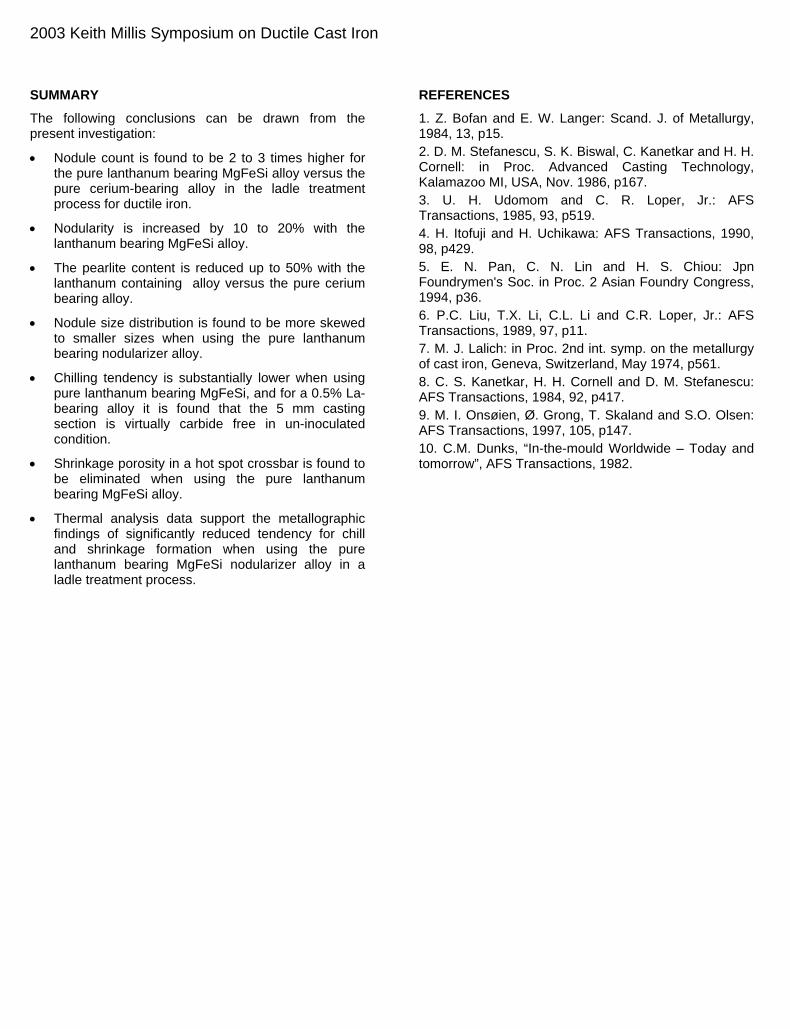
SUMMARY The following conclusions can be drawn from the present investigation:
• Nodule count is found to be 2 to 3 times higher for the pure lanthanum bearing MgFeSi alloy versus the pure cerium-bearing alloy in the ladle treatment process for ductile iron.
• Nodularity is increased by 10 to 20% with the lanthanum bearing MgFeSi alloy.
• The pearlite content is reduced up to 50% with the lanthanum containing alloy versus the pure cerium bearing alloy.
• Nodule size distribution is found to be more skewed to smaller sizes when using the pure lanthanum bearing nodularizer alloy.
• Chilling tendency is substantially lower when using pure lanthanum bearing MgFeSi, and for a 0.5% La-bearing alloy it is found that the 5 mm casting section is virtually carbide free in un-inoculated condition.
• Shrinkage porosity in a hot spot crossbar is found to be eliminated when using the pure lanthanum bearing MgFeSi alloy.
• Thermal analysis data support the metallographic findings of significantly reduced tendency for chill and shrinkage formation when using the pure lanthanum bearing MgFeSi nodularizer alloy in a ladle treatment process.
REFERENCES 1. Z. Bofan and E. W. Langer: Scand. J. of Metallurgy, 1984, 13, p15. 2. D. M. Stefanescu, S. K. Biswal, C. Kanetkar and H. H. Cornell: in Proc. Advanced Casting Technology, Kalamazoo MI, USA, Nov. 1986, p167. 3. U. H. Udomom and C. R. Loper, Jr.: AFS Transactions, 1985, 93, p519. 4. H. Itofuji and H. Uchikawa: AFS Transactions, 1990, 98, p429. 5. E. N. Pan, C. N. Lin and H. S. Chiou: Jpn Foundrymen's Soc. in Proc. 2 Asian Foundry Congress, 1994, p36. 6. P.C. Liu, T.X. Li, C.L. Li and C.R. Loper, Jr.: AFS Transactions, 1989, 97, p11. 7. M. J. Lalich: in Proc. 2nd int. symp. on the metallurgy of cast iron, Geneva, Switzerland, May 1974, p561. 8. C. S. Kanetkar, H. H. Cornell and D. M. Stefanescu: AFS Transactions, 1984, 92, p417. 9. M. I. Onsøien, Ø. Grong, T. Skaland and S.O. Olsen: AFS Transactions, 1997, 105, p147. 10. C.M. Dunks, “In-the-mould Worldwide – Today and tomorrow”, AFS Transactions, 1982.
2003 Keith Millis Symposium on Ductile Cast Iron
Modeling, Model Verification, and Defect Formation in Iron Castings
Wanliang Sun, Preston Scarber, Hanjun Li, and Charles E. Bates University of Alabama at Birmingham, Birmingham, Alabama
ABSTRACT Experiments are being conducted in a real-time x-ray system to examine the flow of iron into molds and how the flow characteristics affect defect formation. The purpose is to 1) determine the effects of various gating systems on turbulence and oxide formation, 2) examine the effects of core processing variables on porosity in castings, and 3) extend the data using models for castings that cannot easily be examined in an x-ray system. Mold-metal interface reactions and gas evolution have been observed during and after the metal pouring. The fill behavior and mold-metal reactions significantly affect casting quality. Gas holes and gas pores were found in castings poured turbulently and in castings poured with cores where core permeability was inadequate to allow all gasses to escape. Mold coatings affect gas evolution and the surface quality of castings made in resin bonded molds. Surface defect locations were related to gas bubbling during and after mold filling. Gas pores were also produced by pyrolysis of volatiles in the coating and from the decomposition products of core binders. When volatiles cannot escape through the sand, gas bubbles through the casting and produces gas holes. Cores with inadequate permeability also caused gas to bubble through the metal to produce defects. This research is being conducted to develop procedures for pouring iron inside a vault to visualize and then minimize defect formation, and then extend the technology to castings that cannot easily be poured in the x-ray system through the use of models. The ultimate goal is to develop procedures for pouring and gating that will reduce foundry scrap to negligible values. INTRODUCTION Metal filling of mold cavities has historically been studied using several techniques: 1) removing the mold cope and watching flow through a quartz plate, 2) using real-time x-rays to penetrate the mold and observe metal front movement, 3) using water simulations (Perkins and Bain, 1965; Nguyen and Carring, 1986; Xue et al, 1993), 4) using computer modeling, and 5) embedding position probes to follow metal fronts during filling. However, real-time x-ray systems provide the best method for observing mold filling with minimal external interference (Campbell and Koster, 1994). Fry (1944) was perhaps the first to use a real-time x-ray system to observe metal fill behavior. Others, including St. John et al. (1980), Sirrell and Campbell (1995), Barkhudarov and Williams (1995), Ruiz and Khandia (1995), Sirrell et al. (1996), Yang and Campbell (1998), Jolly et al. (1998) and Schuhmann, Dale, et al. (2000) have used the real-time x-ray observations to compare fill behavior to simulations. X-rays are also used to relate metal filling to casting quality. Ashton and Buhe (1973) used this technique to study the effects of gating system design on defect formation. Stegemann, Reimche, and Schmidbauer (1992) examined defect formation in light metal castings. Lee et al. (1995, 1997, 1997) and Atwood et al. (1999, 2000) constructed an X-ray Temperature Gradient Stage (XTGS) to watch hydrogen porosity develop in aluminum during controlled directional solidification. Sirrell and Campbell (1997) examined the effect of filtration on defect formation, and Rezvani and Campbell (1999) related x-ray observations made during filling to the strength and reliability of cast aluminum. Castings poured with a minimum of turbulence had higher mechanical properties. X-ray technology has also been used to observe metal filling in permanent molds (Schuhmann, Dale, et al., 2000) and lost foam molds (Sun, Littleton, Bates, 2002). By contrast, fewer studies have been conducted using real-time x-ray to study gray iron mold filling, probably because of the higher pouring temperature and greater difficulty of penetrating the metal. Also, relatively few studies have been conducted focusing on gas porosity formation.
2003 Keith Millis Symposium on Ductile Cast Iron
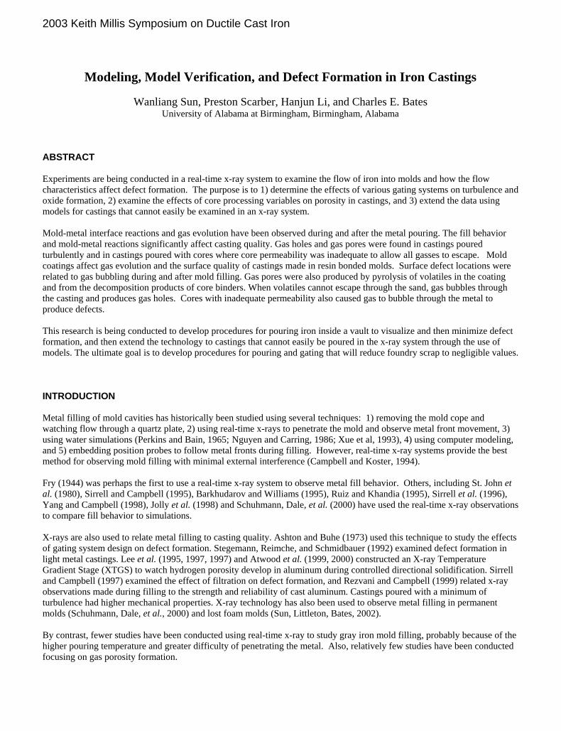
EXPERIMENTAL PROCEDURES A 320 kV real-time x-ray system was used in the current study to observe metal filling, mold-metal reactions, and the defects formed in gray and ductile iron castings. Some molds were coated with commercial mold washes to create a variety of conditions inside the mold cavity. Other molds had cores inserted to observe gas evolution during and after pouring. The effects of the mold conditions, metal fill behavior, and the mold-metal interface reactions were recorded during pouring and subsequently examined to determine the phenomena responsible for defect formation. Uncored Plate Mold The molds used in this study were produced using phenolic urethane (PUCB), toluene sulphonic acid catalyzed phenolic (TSAP) resin, and Alpha Set resin binders. Most cores examined to date have been made by the shell (Kroning) process. The sand used has been as coarse as GFN-25 and as fine as GFN-80. The appearance and dimensions of the uncored plate mold are illustrated in Figure 1. The casting cavity was a plate with dimensions of 102mm × 102mm × 13mm (4in × 4in × 0.5in). The mold had a tapered sprue with a built-in pouring basin on top of the sprue. The gating system was choked at the ingate, making the gating system a pressurized system. Selected molds were coated with a commercial alcohol-based wash to create various mold permeability conditions. In all cases, the coatings were sprayed on and the alcohol burned off. Thicker coatings producing lower mold permeability were obtained by applying more than one coating. The alcohol in each layer was burned off prior to applying the next layer. Coating thicknesses were measured using a thickness gauge and the value recorded.
(a) (b)
Fig. 1. (a) Macrograph of experimental plate mold. (b) Dimensions of the plate mold. Cored Plate Mold The plate mold containing a core is shown in Figure 2 with dimensions in millimeters. The sprue was slightly tapered and the pouring basin on top of the sprue was on the opposite half of the mold. The gating system was choked at the ingates, which resulted in a slightly pressurized system. The cores used to date were made using the shell process. The cores were stored in a dry environment and were individually wrapped to avoid contamination or scratching of the surfaces.

2003 Keith Millis Symposium on Ductile Cast Iron
Fig. 2. Solid model of the cored plate casting used in the real-time x-ray observations. All dimensions are in
millimeters. Vibration Dampener Mold A dimensioned solid model of the vibration dampener casting is shown in Figure 3. The sprue for this casting was untapered and the dimensions of all flow channels increased as liquid approached the casting cavity, resulting in an unpressurized gating system. A stoppered basin was placed above the sprue to produce consistent pouring conditions. .
Fig. 3. Solid model of the vibration dampener used in the real-time x-ray observations and computer simulations. All dimensions are in millimeters.

2003 Keith Millis Symposium on Ductile Cast Iron
MELTING AND POURING Castings were poured with both gray iron and ductile iron. The gray iron was a class 30 material containing nominally 3.4% C, 2.2% Si, 0.60% Mn, and 0.08% S. The iron was inoculated with a 0.2% addition of 75% ferrosilicon during tapping from the melting furnace and poured at a temperature of approximately 2500° F. Ductile iron castings contained approximately 3.65% C, 2.5% Si, 0.40% Mn, and 0.035% Mg. The base iron was melted using steel scrap, silicon carbide, crystalline graphite, and ferro-manganese. The irons were inoculated with a 0.5% addition of 75% inoculating grade ferrosilicon during tapping from the furnace. All iron was melted in a 45kg (100lb) induction furnace, tapped, and poured in the range of 2500°F -2600°F (1370°C -1425°C). X-RAY SYSTEMS There are two x-ray units inside the vault. One system, a 320 kV tube having a focal spot size of 0.8mm × 0.8mm, is used to observe metal flow into molds. The x-rays are imaged on a 9” diameter tri-field image intensifier and photographed using a Sony XC75CCD camera. A microprocessor console integrates the operation of this unit so that images are captured correctly. The second unit consists of a 160 kV micro-focus x-ray tube, with a focal spot ranging in size from 5 to 200 microns depending on the current applied, and an A-SI (amorphous silicon) digital detector having an active area of 203 × 254mm and 1997 × 2592 (3.1million) pixels. Each pixel in the digital detector has a 12-bit gray scale density resolution when maximum resolution is desired. The detector can provide 4096 shades of gray at a frame speed of 7 frames per second. At a frame rate of 30 frames per second, there are 256 shades of gray. Both x-ray systems can be used for real-time and static examinations of cast parts, although the micro-focus unit does not have the penetrating ability of the 320 kV tube. In this study, the 320kV system was used for real time observations, and the 160kV digital system was used to evaluate internal casting quality.
(a) (b)
Fig. 4. (a) Overview the x-ray system. (b) Close-up view of mold and pouring cart. A view of the x-ray vault with the door open is illustrated in Figure 4 (a), and a mold and the pouring cart is shown in Figure 4(b). Although either horizontally split or vertically split molds can be poured in the x-ray vault, the molds used in this study were poured with a vertical parting line. Mold halves are assembled outside the x-ray vault, and the halves locked together with wood plates and threaded rod. The support plates allow green sand as well as no-bake moles to be poured. There is a spacer between the mold and the support plate to allow gas to freely exit from the back of the mold. Each mold is placed inside the x-ray vault, a cart holding a ladle of liquid metal is positioned in the vault using steel tracks, and the metal remotely poured from the pouring cart into the mold. The pouring cart can be raised or lowered to accommodate various mold sizes. The pouring rate is controlled manually by watching output from two cameras in the vault. X-rays pass through the mold and are projected onto a cesium-iodide (CsI) fluoroscopic screen, photographed at 30 frames per second using a CCD camera, and recorded on a VCR. The video images are later converted to digital files for image processing.
2003 Keith Millis Symposium on Ductile Cast Iron
Velocity profiles were processed to obtain isochronal metal front profile maps. Changes in the metal front profile could be clearly seen, and instantaneous metal fill velocities calculated using time steps of 0.1 sec. The front profile maps were used to compare the metal filling using different mold conditions. Fill behavior has been compared to computer models in some cases to verify and / or adjust the models. This allows models to be used outside the range of mold sizes that can be poured and viewed in the vault. RESULTS AND DISCUSSION MOLD COATING EFFECTS ON FILLING
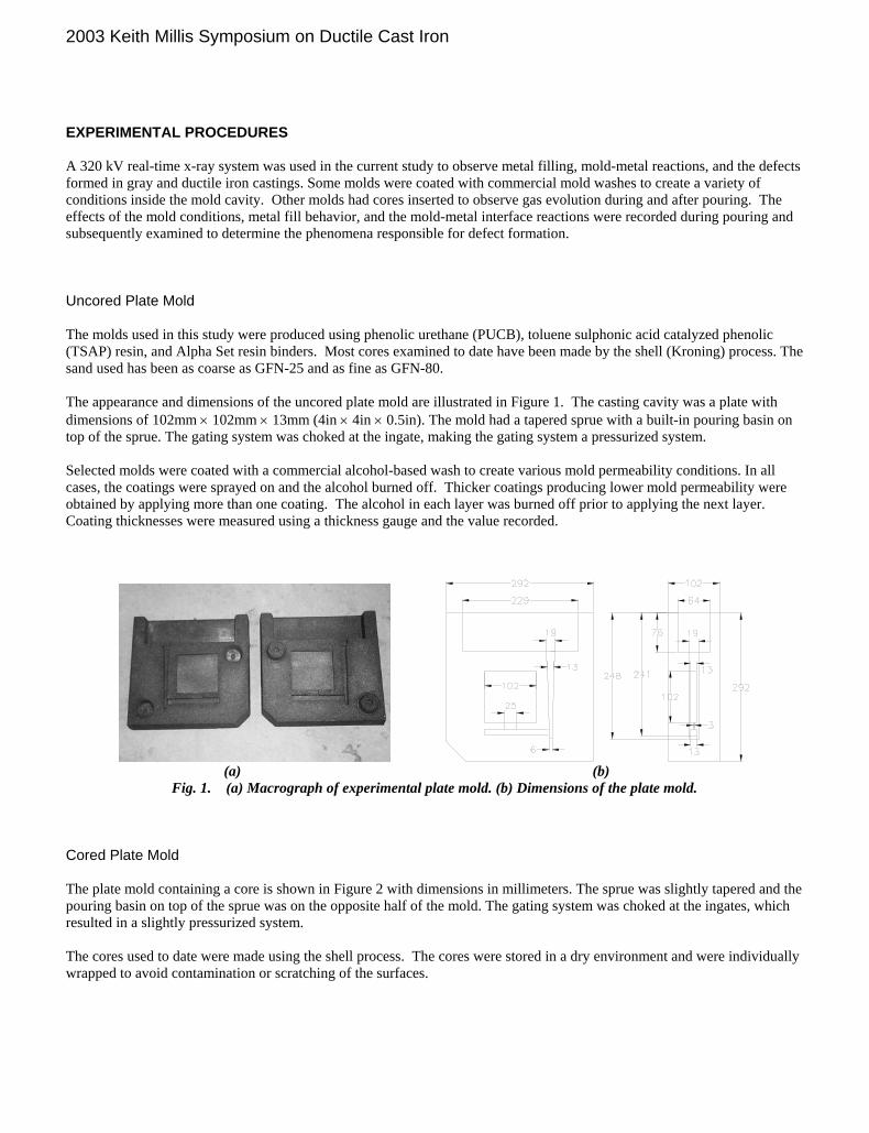
Fig. 5. Video stills of the metal filling of the mold without coating.
Several video “frames” at different times during filling are illustrated in Figure 5. The mold wall has its maximum permeability when no coating is used, and the metal entered the mold cavity at about 90 cm/s (35in/s). After the molten metal hit the mold wall, it splashed, swirled, and entrapped air. A low pressure region near the junction of the sprue with the horizontal runner was found to persist over about 75 % of the pouring event. The metal filling was so turbulent that it was difficult to make an isochronal metal front map. Coating the mold reduced the mold permeability and metal flow rate into the mold. Isochronal front maps at 0.1 second after the start of pouring of molds with no coating, one layer, two layers, and three layers of coating are illustrated in Figure 6. These maps were obtained by tracing the metal front at 0.1 second time intervals. The metal fill rate became slower and smoother when thicker coatings were applied. The increased coating thickness had two effects: (1) it reduced the permeability of the mold and (2) produced more gas as the volatiles in the coating evolved. These factors increased the gas backpressure and slowed the fill rate.

2003 Keith Millis Symposium on Ductile Cast Iron
(a) No coating (b) One layer (8mils) (c) Two layers (14 mils) (d) Three layers (21mils) Fig. 6. Isochronal metal front profile map of the metal filling in sand molds coated at different thickness. The maps were
obtained by tracing the metal flow at every 0.1s. MOLD - METAL INTERACTIONS Cold Shot The high velocity metal stream caused splashing and metal shot formation when the mold was poured without any coating. The shot oxidized and then froze when it hit a cold portion of the mold. Cold shot on the mold wall is illustrated in Figure 7(b). The cold shot may be flushed back into the casting by the whirling metal flow to produce internal anomalies.
(a) (b) (c)
Fig. 7. Cold shot caused by splashing during mold filling. Air Entrapment Some air entrapment was also observed as metal was poured into uncoated molds. The whirling metal illustrated in Figure 8(a) entrapped some air. Most of the nitrogen probably escaped, but the oxygen reacted with iron to produce reoxidation products that can be found both on the surface and on the interior of castings. Air entrapment was also observed in the metal filling of coated molds. Mold filling was turbulent near the ingate, and air entrapment occurred as illustrated in Figure 8(b). Although the entrained air later disappeared, iron and silicon oxides were formed which affect surface quality and machinability.

2003 Keith Millis Symposium on Ductile Cast Iron
(a) (b)
Fig. 8. (a) Metal filling an uncoated mold; (b) Metal filling a coated mold Plate Casting Quality Mold reactions affect the surface and internal casting quality. The surface quality was described using macrographs of the as-cast surfaces, and the internal casting quality was evaluated using digital x-rays. The advantage of digital macrographs and x-rays is that they are easily transported for viewing by other investigators, and analysis can be conducted with image analysis software. The appearance of a casting poured in an uncoated mold was shown in Figure 9(a). The surface of the casting was rough and burned-on sand was present over the surface. A gas hole marked by “A” is illustrated in Figure 9(a). This gas hole was also seen in the digital x-ray in Figure 9(b). More pores are visible in the x-ray which indicates do not extend to the casting surface. The surface of a casting poured in a coated mold is illustrated in Figure 10. The coating improved the casting surface finish as illustrated in Figure 10(a) and (b) and reduced the number of internal defects compared to the uncoated mold (see Figure 9 (b)). Some gas porosity is still present, indicating that other factors such as the gating system must be changed to produce a quality casting.
A B
(a) Fig. 9. (a) Photograph a
(b)
nd (b) Digital X-Ray of casting.
2003 Keith Millis Symposium on Ductile Cast Iron
A B
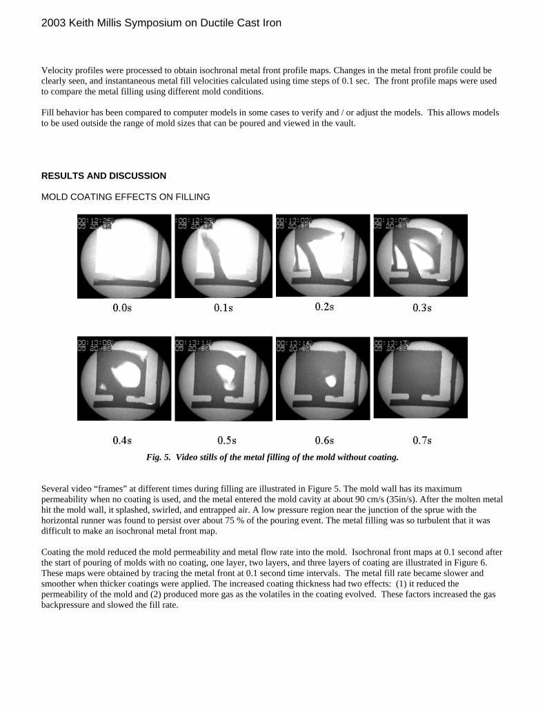
(a) (b) Fig 10. (a) Photograph and (b) digital x-ray of a casting with mold wash
Core Gas
(a) (b)
Fig. 11. Mold gas observed in the metal filling. (a) Gas Generation; (b)Gas Entrapped in the metal. Core gas produced during filling a cored plate mold with ductile iron is illustrated in Figure 11. As the binder decomposed, the gas will either exit through the core or bubble through the metal to produce porosity. This gas bubble damage can be aggravated by residual volatiles in the mold coating.
0.00s 0.40s 1.00s 1.20s 1.40s
1.50s 2.00s 2.10s 2.20s 2.30s
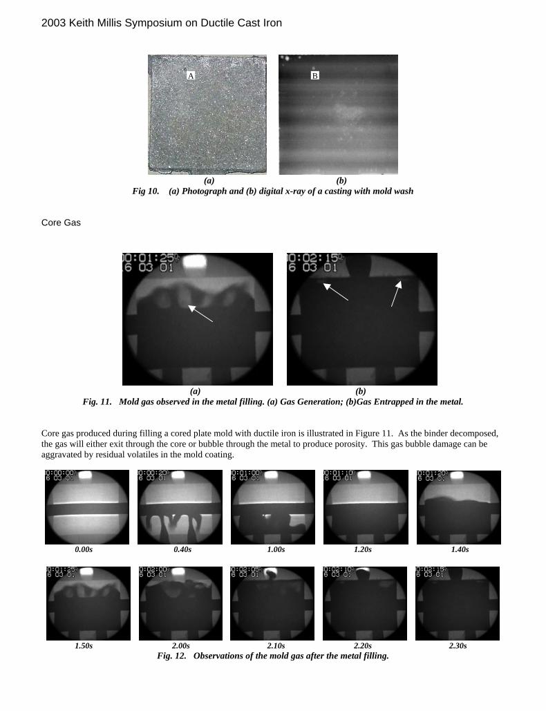
Fig. 12. Observations of the mold gas after the metal filling.
2003 Keith Millis Symposium on Ductile Cast Iron
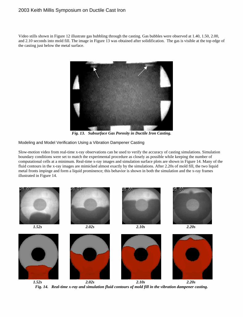
Video stills shown in Figure 12 illustrate gas bubbling through the casting. Gas bubbles were observed at 1.40, 1.50, 2.00, and 2.10 seconds into mold fill. The image in Figure 13 was obtained after solidification. The gas is visible at the top edge of the casting just below the metal surface.
Fig. 13. Subsurface Gas Porosity in Ductile Iron Casting.
Modeling and Model Verification Using a Vibration Dampener Casting Slow-motion video from real-time x-ray observations can be used to verify the accuracy of casting simulations. Simulation boundary conditions were set to match the experimental procedure as closely as possible while keeping the number of computational cells at a minimum. Real-time x-ray images and simulation surface plots are shown in Figure 14. Many of the fluid contours in the x-ray images are mimicked almost exactly by the simulations. After 2.20s of mold fill, the two liquid metal fronts impinge and form a liquid prominence; this behavior is shown in both the simulation and the x-ray frames illustrated in Figure 14.
1.52s 2.02s 2.10s 2.20s
1.52s 2.02s 2.10s 2.20s
Fig. 14. Real-time x-ray and simulation fluid contours of mold fill in the vibration dampener casting.

2003 Keith Millis Symposium on Ductile Cast Iron
Extending Models to More Complex Castings
Design #1
Design #2
Design #1
Design #2
(a) (b)
Figure 15. (a) SEM backscatter electron image of a reoxidation defect in gray iron – 250x magnification. (b) Plot of liquid surface area vs. fill fraction for an engine block with two different gating systems.
Research to determine riser size and placement has been underway for at least a century, and within the last 20 years, risering principles have been incorporated into all commercial computer codes. Much less has been done on the mold filling process. Oxidation during pouring is responsible for much of the dross and surface defects on both gray and ductile iron castings. A typical dross defect in a gray iron casting found during machining is illustrated in Figure 15a, and those in ductile iron are similar. Filling of molds made on a Hunter or small Disa can be viewed directly with the real time x-ray system. But the system is more valuable when used to compare fill patterns with simulation results and then extend use simulations to predict turbulence in castings too large or complex to view with an x-ray system. The time and area of metal contact with air during pouring and mold filling largely controls surface and subsurface inclusion formation. Data and theories were incorporated in a simulation of an eight cylinder engine block, and the results are illustrated in Figure 15b. Several simulations were run and the original gating system redesigned to reduce metal turbulence and splashing. Initially, the metal contact with air was over 8 m² sec. Gate modification reduced exposure to 4 m² sec. The oxide defect scrap rate on the block with the original production gating system was about 5%. When gate changes were incorporated to reduce turbulence and surface contact with air, the oxide defect rate dropped to 0% and has been at this value for almost a year. SUMMARY This study was conducted to e plore the use of real time x-rays for observing defect formation during filling molds with iron. Sand molds bonded with vario s binders were coated with various amounts of an alcohol-based mold wash. No variations were made in the gating syste Procedures were developed forecorded and later analyzed tomade:
xu
m.
r pouring iron and obs rving mold filling using high-energy x-rays. The fill patterns were study the formation o
e
f surface and internal casting defects. The following observations were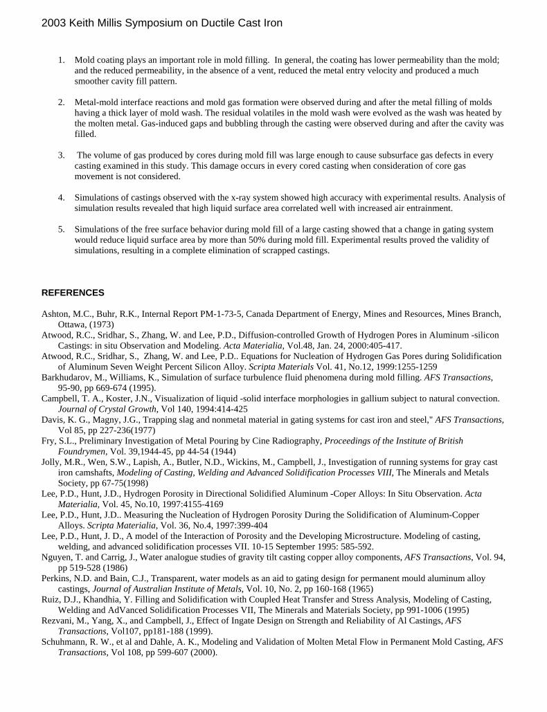
2003 Keith Millis Symposium on Ductile Cast Iron
1. Mold coating plays an important role in mold filling. In general, the coating has lower permeability than the mold;
and the reduced permeability, in the absence of a vent, reduced the metal entry velocity and produced a much smoother cavity fill pattern.
2. Metal-mold interface reactions and mold gas formation were observed during and after the metal filling of molds
having a thick layer of mold wash. The residual volatiles in the mold wash were evolved as the wash was heated by the molten metal. Gas-induced gaps and bubbling through the casting were observed during and after the cavity was filled.
3. The volume of gas produced by cores during mold fill was large enough to cause subsurface gas defects in every
casting examined in this study. This damage occurs in every cored casting when consideration of core gas movement is not considered.
4. Simulations of castings observed with the x-ray system showed high accuracy with experimental results. Analysis of
simulation results revealed that high liquid surface area correlated well with increased air entrainment. 5. Simulations of the free surface behavior during mold fill of a large casting showed that a change in gating system
would reduce liquid surface area by more than 50% during mold fill. Experimental results proved the validity of simulations, resulting in a complete elimination of scrapped castings.
REFERENCES Ashton, M.C., Buhr, R.K., Internal Report PM-1-73-5, Canada Department of Energy, Mines and Resources, Mines Branch,
Ottawa, (1973) Atwood, R.C., Sridhar, S., Zhang, W. and Lee, P.D., Diffusion-controlled Growth of Hydrogen Pores in Aluminum -silicon
Castings: in situ Observation and Modeling. Acta Materialia, Vol.48, Jan. 24, 2000:405-417. Atwood, R.C., Sridhar, S., Zhang, W. and Lee, P.D.. Equations for Nucleation of Hydrogen Gas Pores during Solidification
of Aluminum Seven Weight Percent Silicon Alloy. Scripta Materials Vol. 41, No.12, 1999:1255-1259 Barkhudarov, M., Williams, K., Simulation of surface turbulence fluid phenomena during mold filling. AFS Transactions,
95-90, pp 669-674 (1995). Campbell, T. A., Koster, J.N., Visualization of liquid -solid interface morphologies in gallium subject to natural convection.
Journal of Crystal Growth, Vol 140, 1994:414-425 Davis, K. G., Magny, J.G., Trapping slag and nonmetal material in gating systems for cast iron and steel," AFS Transactions,
Vol 85, pp 227-236(1977) Fry, S.L., Preliminary Investigation of Metal Pouring by Cine Radiography, Proceedings of the Institute of British
Foundrymen, Vol. 39,1944-45, pp 44-54 (1944) Jolly, M.R., Wen, S.W., Lapish, A., Butler, N.D., Wickins, M., Campbell, J., Investigation of running systems for gray cast
iron camshafts, Modeling of Casting, Welding and Advanced Solidification Processes VIII, The Minerals and Metals Society, pp 67-75(1998)
Lee, P.D., Hunt, J.D., Hydrogen Porosity in Directional Solidified Aluminum -Coper Alloys: In Situ Observation. Acta Materialia, Vol. 45, No.10, 1997:4155-4169
Lee, P.D., Hunt, J.D.. Measuring the Nucleation of Hydrogen Porosity During the Solidification of Aluminum-Copper Alloys. Scripta Materialia, Vol. 36, No.4, 1997:399-404
Lee, P.D., Hunt, J. D., A model of the Interaction of Porosity and the Developing Microstructure. Modeling of casting, welding, and advanced solidification processes VII. 10-15 September 1995: 585-592.
Nguyen, T. and Carrig, J., Water analogue studies of gravity tilt casting copper alloy components, AFS Transactions, Vol. 94, pp 519-528 (1986)
Perkins, N.D. and Bain, C.J., Transparent, water models as an aid to gating design for permanent mould aluminum alloy castings, Journal of Australian Institute of Metals, Vol. 10, No. 2, pp 160-168 (1965)
Ruiz, D.J., Khandhia, Y. Filling and Solidification with Coupled Heat Transfer and Stress Analysis, Modeling of Casting, Welding and AdVanced Solidification Processes VII, The Minerals and Materials Society, pp 991-1006 (1995)
Rezvani, M., Yang, X., and Campbell, J., Effect of Ingate Design on Strength and Reliability of Al Castings, AFS Transactions, Vol107, pp181-188 (1999).
Schuhmann, R. W., et al and Dahle, A. K., Modeling and Validation of Molten Metal Flow in Permanent Mold Casting, AFS Transactions, Vol 108, pp 599-607 (2000).

2003 Keith Millis Symposium on Ductile Cast Iron
Stegemann, D., Reimache, W. and Schmidbauer, J., Investigation of light metal casting process by real time micro-focus
radioscopy. The European Journal of Non-destructive Testing, Vol1, No.3, Jan 1992:107-117 Sirrell, B., Campbell, J., Real-time X-ray Radiography of Mould Filling, CASTCON '95 (Conference proceedings), Institute
of British Foundrymen: 15-16 June 1995 Sirrell, B., Holliday, M., Campbell, J., Benchmark testing the flow and solidification modeling of Al castings, Journal of
materials (JOM), Vol. 48, No. 3, pp 20-23(1996) Sirrell, B., Campbell, J., The effects of Mold Filtration in the Reduction of Casting Defects due to Surface Turbulence During
Mold Filling, AFS Transactions, Vol105, pp645-654 (1997). St.John, Davis, D.H., K.G., Magny, J.G., Computer Modeling and Testing of Metal Flow in Gating Systems, Physical
Metallurgy Research Laboratories Report MRP/PMRL 80- 12 (J), Canmet Canada Centre for Mineral and Energy Technology. (1980).
Sun, W., Littleton, H.E., Bates, C.E., Real time X-Ray Observations on the Metal Filling of Lost Foam Aluminum Castings, AFS Transactions, Vol 110, pp 1347-1356 (2002).
Xue, X., Hansen, S.F., Hansen, P.N., "Water analog study of effects of gating designs on inclusion separation and mold fiftg control," AFS Transactions, pp 199-209 (1993).
Yang, X. Campbell, J., Liquid Metal Flow in a Pouring Basin, International Journal of Cast Metals Research, No. 10, pp239-253 (1998)

The Ductile Iron News
file:///C|/WEBSHARE/062013/magazine/2006_1/nbriefs.htm[7/1/2013 2:12:41 PM]
To Promote the production and application of ductile iron castings Issue 1, 2006
FEATURES
• Ductile Iron Society ProductionSeminar
PDF ARTICLES
• The Production of AustemperedDuctile (ADI)
•A New Method for Chill andShrinkage Control in Ladle TreatedDuctile Iron
• Modeling, Model Verification, andDefect Formation in Iron Castings
DEPARTMENTS
• News Briefs
• Advertisers
• Back Issues
• DIS Home Page
News BriefsMEETINGS - BUSINESS - PEOPLE
MEETINGS
The Ductile Iron Society 2006 Annual Meeting will be held onJune 21-23, 2006 at the Wynfrey Hotel at the Riverchase Galleria,in Birmingham, Alabama. The meeting will feature visits toCitation Foam Castings and Glidewell Specialties Foundry.
The Ductile Iron Society 2006 Fall Meeting will be held inMonterey, Mexico in October. The meeting will feature tours ofBlackhawk de Mexico, CIFUNSA and Grede Proeza along with afull technical program. The exact dates and the host hotel will beannounced later.
BUSINESS
Ashland’s Cleveland East Facility Adds Automation and FindsAdditional Capacity
DUBLIN, Ohio – Many books and seminars stress the overlookedopportunities in finding additional efficiencies from existingoperations. Ashland Casting Solutions, a business group of AshlandSpecialty Chemical, a division of Ashland Inc. (NYSE:ASH), puttheory into practice by implementing a combination of programs tofind additional capacity at its coatings facility in Cleveland.
“We changed the operations to place initial ingredients in positionsso they would be where we needed them when we needed them,”said Russ Montgomery, plant manager for Ashland’s ClevelandEast facility. “We also automated our ingredient measuring system.These changes not only increased production efficiency, but theysupported our goal of a workplace with zero incidents throughimproved housekeeping. We also reduced manual handling ofheavy materials, while further limiting the potential for employeeexposures to ingredients.”
The automation and increased production efficiency resulted inadditional production capacity that allowed the Cleveland facility toadd green-sand release agent production, which was previouslyproduced elsewhere. This was accomplished by consolidatingcurrent production to fewer units, thus freeing up a unit for thegreen-sand release agent production.
The production transfer to the Cleveland facility has also improvedupon green-sand release agent quality by utilizing in-houselaboratory capabilities. It has allowed additional product portfolioimprovements with an emphasis on finding additionalenvironmentally-considerate enhancements for release agenttechnology. “It’s all about our customers. We took a step back,looked at our operations and implemented changes. Our processimprovements have given us greater control, and as a result, we
susan
Rectangle

The Ductile Iron News
file:///C|/WEBSHARE/062013/magazine/2006_1/nbriefs.htm[7/1/2013 2:12:41 PM]
have been able to provide more value to our customers,” addedMontgomery.
Ashland Casting Solutions, a business group of Ashland SpecialtyChemical, is a leader in supplying products, processes andtechnologies to the global metal casting marketplace. The group hasoperations (including licensees and joint ventures) in 21 countries.
Ashland Specialty Chemical, a division of Ashland Inc., is aleading, worldwide supplier of specialty chemicals servingindustries including adhesives, automotive, composites, metalcasting, merchant marine, paint, paper, plastics, watercraft andwater treatment. Visit www.ashspec.com to learn more about theseoperations.
Ashland Inc. (NYSE: ASH) is a Fortune 500 chemical andtransportation construction company providing products, servicesand customer solutions throughout the world. To learn more aboutAshland, visit www.ashland.com.
PEOPLE
AFS Strengthens Technical Resources
Schaumburg, Ill. To strengthen the technical resources available tothe North American metalcasting industry, the American FoundrySociety Inc. (AFS), Schaumburg, Ill., announced Scott Lammersas its Technical Director of Ferrous Casting.
Lammers graduated from the University of Missouri at Rolla with aB.S. in Metallurgical Engineering. Later, he went on to acquire hisMasters of Business Administration from Loyola University inChicago. Lammers spent the last 20 years working in and with themetalcasting industry as the Chief Metallurgist for WellsManufacturing, Castwell Division, Skokie, Ill., as a sales engineerfor Aurora Metals, Montgomery, Ill., and as an account managerfor Bremen Castings, Bremen, Ind.
At AFS, Lammers is the liaison for the Cast Iron (Div. 5), Steel(Div. 9), and Melting (Div. 8) Technical Committees. He will alsoassist AFS member foundries with metallurgical and process issues.In addition, he will be coordinating with the AFS Washington D.C.office to secure research grants from various government agencies.
“The addition of Scott Lammers to our technical staff continues tostrengthen AFS’ position as the technical resource for the NorthAmerican metalcasting industry,” said Jerry Call, AFS executivevice president.
Headquartered in Schaumburg, Ill., AFS is a not-for-profittechnical and management society that has existed since 1896 toprovide and promote knowledge and services that strengthen themetalcasting industry for the ultimate benefit of its customers andsociety.
Ashland Casting Solutions Introduces Cellular Ceramic Filtersfor Metalcasting
DUBLIN, Ohio – A new line of extruded ceramic filters for liquid

The Ductile Iron News
file:///C|/WEBSHARE/062013/magazine/2006_1/nbriefs.htm[7/1/2013 2:12:41 PM]
metal filtration from Ashland Casting Solutions, a business groupof Ashland Specialty Chemical, a division of Ashland Inc. (NYSE:ASH), provides additional options for metal casting facilities in theU.S.
EXACTFLO™ cellular ceramic filters from Ashland offer a varietyof sizes and cell configurations designed to meet or exceeddemanding performance standards. EXACTFLO™ filters provideconsistent inclusion removal and flow control and can withstandpouring temperatures up to 2,650 degrees Fahrenheit. The filters,made from alumina/silica ceramic, are targeted for use with grayand ductile iron but are also effective with aluminum and othernon-ferrous alloys.
“We are very pleased to add the EXACTFLO™ ceramic filters toour product offering in the U.S.,” said Mike Swartzlander, vicepresident, Ashland Specialty Chemical, and general manager,Ashland Casting Solutions. “Our continuing efforts to expand ourproduct lines here and globally demonstrate our continuedemphasis to provide solutions to our customers.”
EXACTFLO™ ceramic filters are available in a range of sizesfrom 37 to 81 mm square and with square or delta (triangular) cellsranging in size from 100 cells per square inch (CSI) to 300 CSI.These filters can be placed either vertically or horizontally withinthe gating system of the mold.
For more information about EXACTFLO ceramic filters, contact anAshland Casting Solutions representative.
Ashland Casting Solutions, a business group of Ashland SpecialtyChemical, is a leader in supplying products, processes andtechnologies to the global metal casting marketplace. The group hasoperations (including licensees and joint ventures) in 21 countries.
Ashland Specialty Chemical, a division of Ashland Inc., is aleading, worldwide supplier of specialty chemicals servingindustries including adhesives, automotive, composites, metalcasting, merchant marine, paint, paper, plastics, watercraft andwater treatment. Visit www.ashspec.com to learn more about theseoperations.
Ashland Inc. (NYSE: ASH) is a FORTUNE 500 chemical andtransportation construction company providing products, servicesand customer solutions throughout the world. To learn more aboutAshland, visit www.ashland.com.
Back to top
View Ductile Iron Related Publications
Located in Strongsville, Ohio, USA15400 Pearl Road, Suite 234; Strongsville,Ohio 44136 Billing Address: 2802 Fisher Road, Columbus, Ohio 43204 Phone (440) 665-3686; Fax (440) 878-0070email:[email protected]


![Austempered Ductile Iron [Adi]1](https://static.fdocuments.net/doc/165x107/55332f154a79592c4f8b4800/austempered-ductile-iron-adi1.jpg)


![A Us Tempered Ductile Iron [Adi]-Small](https://static.fdocuments.net/doc/165x107/577d24511a28ab4e1e9c2d30/a-us-tempered-ductile-iron-adi-small.jpg)