Modelling Velocity in Carbonates Using Dual Porosity DEM Model

Dual Scale Porosity and Interlaminar Properties ofComposite Materials
MOHAMMAD WASEEM TAHIR
Doctoral ThesisStockholm, Sweden 2014

TRITA AVE 2014:15ISSN 1651-7660ISBN 978-91-7595-185-0
KTH School of Engineering SciencesSE-100 44 Stockholm
SWEDEN
Akademisk avhandling som med tillstånd av Kungl Tekniska högskolan framläg-ges till offentlig granskning för avläggande av teknologie doktorsexamen i lättkon-struktioner tisdagen den 17 juni 2014 klockan 10:15 i Kollegiesalen Brinellvägen 8,Kungliga Tekniska Högskolan, Stockholm.
© Mohammad Waseem Tahir, 2014
Tryck: Universitetsservice AB
Abstract
In the strive towards reduced fuel consumption and lower emissions, lowstructural weight is becoming a key factor in the design of advanced vehicleand aerospace structures. Whereas most traditional construction materialsare seemingly reaching their limitations, composite materials with their highspecific properties offer possibilities to further reduce weight. In high demandstructural applications, the quality of the composite material is of utmost im-portance, requiring the material to be void free and the matrix well distributedas a binder for the load carrying reinforcement. To achieve proper wetting ofthe fibres, knowledge of the flow resistance of the porous fibre reinforcementis required. It is normally expressed in terms of permeability.
Fibre reinforcements in composite materials are normally regarded as aheterogeneous porous media since both fabric and tows are porous but atdifferent length scales. In order to numerically compute the permeability ofsuch media, one of following two approaches can be used. Either filaments areadded one-by-one into the modelled geometry (resolved model) or the towsare considered as porous homogenised media. In the latter case expressionfor the intra-tow permeability is needed.
In this thesis, a porous homogenised tow model is benchmarked with aresolved model to the level of refinement possible without being too expensivecomputationally. Based on this approach, the permeability of complex three-dimensional (3D) textiles is computed utilizing computational fluid dynamics(CFD) analysis. The effect of inter- and intra-tow porosity on the overallpermeability of 2D and 3D structures is analysed and discussed in relationto contradictions found in past studies. A clearer picture of the problem ispresented, which will be helpful in future modelling and understanding of thepermeability of complex structures. In an experimental study, the overall fibrevolume fraction as well as the tow compaction are varied and their influenceon the permeability is measured. Experimental studies show good agreementwith numerical simulations.
The interlaminar shear strength of thermoplastic composite materials isstudied and the influence of specimen size is examined. Using finite element(FE) analysis it is shown that size effects may be partly due to statisticaleffects and partly due to the higher number of composite layers in thickerspecimens.
The effect of processing on the interlaminar delamination toughness of car-bon/polyamide 12 (C/PA12) is studied. It is observed that processing con-ditions have vital effect on the interlaminar delamination of thermoplasticcomposites. The mode I crack energy release rate (GIc) of C/PA12 is foundto be 15 times higher than for conventional thermoset based composites and1.5 times higher than for a thermoset composite with stitched reinforcementthrough the thickness. The best performing C/PA12 composite is manufac-tured in a hydraulic press equipped with a cold tool, thereby showing potentialfor both cost and time efficient manufacturing.
iii
Sammanfattning
Framtidens farkoster måste bli lättare för att medge minskad energiför-brukning och utsläpp under framdrift. Många anser att detta endast kan skegenom ökat användande av kompositmaterial då de konventionella konstruk-tionsmaterialen inte kan pressas till lägre vikt. Kompositer, å andra sidan,har utmärkta mekaniska egenskaper i kombination med låg vikt. En stor ut-maning ligger dock i att uppnå den kvalitet som krävs för materialet i dessahögbelastade applikationer. Detta betyder att kompositen måste vara fri fråndefekter som luftbubblor och att matrisen, bindemedlet, måste vara väl för-delat i den lastbärande fiberarmeringen. För att uppnå vätning av fibrernakrävs kunskap om det porösa fibermaterialets permeabilitet.
Armeringen i kompositmaterial betraktas normalt som heterogena porösamedia eftersom både den textila arkitekturen och de ingående fiberbuntarnaär porösa, men på olika längdskalor. För att beräkna permeabiliteten hos ettsådant material kan en av följande två metoderna användas. Antingen läggsvarje liten fiber in i den modellerade geometrin (upplöst modellering), ellerså betraktas fiberbuntarna som porösa homogeniserade media. I det senarefallet måste värden för fiberbuntens permeabilitet anges.
I avhandlingen implementeras de två modelleringsmetoderna i numeriskaflödessimuleringar (CFD) och resultaten jämförs. Inverkan från porositeteninom och mellan fiberbuntarna analyseras och en möjlig förklaring till en para-dox från tidigare studier presenteras. Detta förväntas vara till hjälp i framtidamodellering av komplexa fiberstrukturer. Vidare beräknas permeabiliteten fören komplex 3-dimensionell (3D) arkitektur genom att i beräkningsmodellenåterskapa fiberbuntarnas verkliga geometri. I en experimentell studie varie-ras volymfraktionen fiber och fiberbuntarnas kompaktion och inverkan påpermeabiliteten undersöks. De experimentalla resultaten överenstämmer välmed nummeriska prediktioner.
Interlaminär skjuvhållfasthet hos termoplastiska kompositmaterial under-söks och specifikt studeras effekten av varierande provstorlekar. I finita ele-ment (FE) analyser visas att storlekseffekten kan bero på statistiska effekter,men delvis även på att tjockare laminat innehåller fler lager och därmed ärrelativt mer homogeniserade än tunna laminat.
Slutligen konstateras det att tillverkningsprocessen har en avgörande inver-kan på det interlaminära delaminationsmotståndet hos termoplastiska kom-positer. Den interlaminära brottsegheten ( GIc ) i Modus I för C/PA12 visarsig vara 15 gånger högre än för konventionella härdplastkompositer och 1,5gånger högre än för en härdplastkomposit med sydd armering genom tjock-leken. Det aktuella materialet tillverkas med fördel genom pressning i kalltformverktyg, vilket ger kort cykeltid och resurseffektiv tillverkning, något somförväntas vara viktigt för framtidens produkter.
iv
To my parents
v


Acknowledgements
The work presented in this thesis was carried out at the Department of Aeronau-tical and Vehicle Engineering, School of Engineering Sciences, Kungliga TekniskaHögskolan (KTH), Stockholm Sweden. The work was funded by Higher EducationCommission of Pakistan (HEC), and Cost Effective Reinforcement of Fastener Ar-eas in Composites (CERFAC) EU FP7 project. The financial funding is gratefullyappreciated.
I would like to express my deepest appreciations to my supervisors Dr. MalineÅkermo and Dr. Stefan Hallström – your endless support, encouraging attitudeand extreme attention to details were all that kept me going on the path of learn-ing. There are always ups and downs on the path of research, your encouragingattitude in the down periods and appreciations in the up periods helped me moveforward in the right direction.
My deepest gratitude to all people at the department of Aeronautical and VehicleEngineering for providing such a nice environment which helped me in researchactivities. I would like to thank Professor Dan Zenkert for introducing me to thedepartment – you are always helpful and kind. I would like to acknowledge theefforts of Dr. Magnus Burman, your valuable comments helped me making a bet-ter layout of this thesis. I am also thankful to Fredrik Stig for being such a nicecolleague, co-worker and friend.
I would like to thank all the administrative staff and laboratory staff who pro-vided me proper guidance and help during these years. The environment around usis made by our colleagues and nice colleagues means nice working environment. Iwould like to express my deepest gratitude to all of my colleagues (past and present)in the department for providing a nice working environment.
I am also thankful to my parents whose guidance and love made it possible forme to reach this level. Many thanks to all my brothers and sisters for your endlesssupport. And on top of all, my wife – Rakshi, I am grateful to you for being such anice partner and friend. In all ups and downs of the research your moral support,love and encouragement helped me move forward. In the end my appreciations goto my little angels, thank you for sitting quiet while I used to work home.
Mohammad Waseem Tahir
Stockholm, May 2014
vii


Dissertation
Paper A
Mohammad Waseem Tahir, Stefan Hallström, Malin Åkermo. Effect of dual scaleporosity on the overall permeability of fibrous structures, Submitted for publication.
Paper B
Fredrik Stig, Mohammad Waseem Tahir, Stefan Hallström, Malin Åkermo, Anexperimental study of the influence from fibre architecture on the permeability of3D-woven textiles. Submitted for publication
Paper C
Mohammad Waseem Tahir, Fredrik Stig, Malin Åkermo, Stefan Hallström. A nu-merical study of the influence from architecture on the permeability of 3D-wovenfibre reinforcement. Submitted for publication
Paper D
Mohammad Waseem Tahir, Stefan Hallström, Malin Åkermo. Specimen size effectson the interlaminar shear strength of thermoplastic composites. Manuscript
Paper E
Mohammad Waseem Tahir, Stefan Hallström, Malin Åkermo. Interlaminar fracturetoughness of carbon/polyamide 12 composites. To be submitted for publication
ix

Parts of this thesis have also been presented as follows:
M. W. Tahir, S. Hallström and M. Åkermo. Inter-laminar strength and 3D re-inforcement of carbon-polyamide 12 composite materials. ECCM-15th EuropeanConference on Composite Materials, Venice, Italy, 24-28 June
x
Division of work between authors
Paper A
Tahir planned and performed the simulations for the dual scale model. Hallströmand Åkermo initiated and guided the work with valuable discussions and revisionsof the paper.
Paper B
Hallström and Stig planned the work, Stig and Tahir carried out the resin infusion,Tahir and Stig compiled the results. Hallström and Åkermo guided the work withvaluable comments and revisions.
Paper C
Hallström and Stig initiated the work, Stig and Tahir performed the meshing, Tahirconducted the computational fluid dynamics (CFD) simulations and compiled theresults. Hallström and Åkermo guided the work with valuable discussions andrevisions.
Paper D
Tahir performed the experimental work and numerical simulations and compiledthe results. Åkermo and Hallström initiated the work and guided it with valuablediscussions and revisions.
Paper E
Tahir performed the experimental work and compiled the results. Åkermo andHallström initiated the work and guided it with valuable discussions and revisions.
xi

List of symbols and abbreviations
φt: Intra-tow porosityφs: Inter-tow porosityφo: Overall porosityφc: Critical porosityφ: Porosity of single scale mediumκt: Intra-tow permeabilityκs: Inter-tow permeabilityκo: Overall permeabilityRf : Radius of filamentsRt: Radius of towκ⊥: Permeability of a single scale medium in filaments’ transverse directionκ‖: Permeability of a single scale medium along filamentsRe : Renold’s numberρ : Densityµ : Dynamic viscosityGIc: Mode I interlaminar fracture toughnessRVE : Representative volume elementSTI ratio: Surface to interior ratioSBS: Short beam shearILSS: Interlaminar shear strengthC/PA12 : Carbon/polyamide 12C/PET : Carbon-polyethylene terephthalateDCB: Double cantilever beamSEM : Scanning electron microscopeFE: Finite elementsCFD: Computational fluid dynamics
xii
Contents
Acknowledgements vii
Dissertation ix
I Introduction 1
1 Background 31.1 FRP constituents . . . . . . . . . . . . . . . . . . . . . . . . . . . . . 41.2 Manufacturing concepts . . . . . . . . . . . . . . . . . . . . . . . . . 61.3 2D vs 3D reinforcement . . . . . . . . . . . . . . . . . . . . . . . . . 101.4 Objective and scope . . . . . . . . . . . . . . . . . . . . . . . . . . . 12
2 Porosity and Permeability 152.1 Porosity . . . . . . . . . . . . . . . . . . . . . . . . . . . . . . . . . . 152.2 Permeability . . . . . . . . . . . . . . . . . . . . . . . . . . . . . . . 152.3 Permeability of 3D-reinforced composites . . . . . . . . . . . . . . . 20
3 Interlaminar properties of composites 233.1 Interlaminar shear properties-size effects . . . . . . . . . . . . . . . . 233.2 Interlaminar fracture toughness . . . . . . . . . . . . . . . . . . . . . 25
4 Contribution to the field 27
5 Summery of appended papers 29
6 Future work 31
Bibliography 33
II Appended papers 39
xiii


Part I
Introduction
1


Introduction 3
1 Background
Economic, environmental and other challenges in the new era bring different needsfor materials. There are many engineering applications where weight reduction isthe primary concern without compromising strength or stiffness. Some of theseapplications are shown in Fig. 1. Fibre reinforced polymers (FRP) are emergingrapidly in the advanced applications due to their light weight.
Figure 1: Different applications of advanced materials, (courtesy of explainthat-stuff.com and bigfoto.com).
An aircraft designer, for example prefers a light weight material but with thesame or higher strength. Because a lightweight aircraft can achieve more mileagefor the same amount of fuel in comparison to a heavier one. The same is true forautomotive and other means of transport. However, motivation for light weightmaterials is not limited to these fields, one can find their applications in the dailylife as well. A tennis player, for example, would like to have a durable tennis racketwhich does not break during a game. However, in order to play a long tough gamefor victory, she/he would certainly like to have a lighter racket. There are manymore applications of composite materials, for example ships, boats, microelectronicdevices, medical equipment, chemical processing equipment, satellites, spacecraftetc.
FRP consist of two or more constituents which are normally based on a ma-trix and a reinforcement. While metals have the same strength in all directions,composites can be made strong in preferred directions. For example a unidirec-tional composite material will be very strong in the fibres’ longitudinal directionbut subsequently weaker in the transverse directions. Other benefits of compos-ite materials include excellent fatigue resistance, good dimensional stability, lowthermal expansion, excellent corrosion resistance etc. [1].
4 Mohammad Waseem Tahir
1.1 FRP constituents
1.1.1 Reinforcements and their forms
The macroscopic strength and stiffness of the composite material as an ideal casedepends on the reinforcement because it bears most of the structural load in ten-sion. The reinforcement can be found in different shapes, for example particles,nano fibres, short fibres and continuous fibres. Continuous fibres may either berandomly distributed or aligned in the longitudinal direction inside the matrix.Since the reinforcement is the main load bearing constituent in composite struc-ture, a common type of reinforcement in composite manufacturing is continuousaligned fibres [2]. Different types of fibres are available, for example glass, carbon,aramid and polymer etc. Fibres used in the composite field are in general verysmall in cross section, for example the diameter of glass fibres ranges from 3µm to25µm. The diameter of carbon fibres ranges from 4µm to 11µm [2]. For most com-
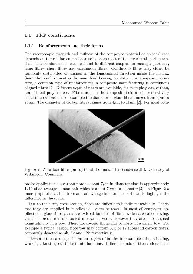
Figure 2: A carbon fibre (on top) and the human hair(underneath). Courtesy ofWikimedia Commons.
posite applications, a carbon fibre is about 7µm in diameter that is approximately1/10 of an average human hair which is about 70µm in diameter [3]. In Figure 2 amicrograph of a carbon fibre and an average human hair is shown to highlight thedifference in the scales.Due to their tiny cross section, fibres are difficult to handle individually. There-
fore they are supplied in bundles i.e. yarns or tows. In most of composite ap-plications, glass fibre yarns are twisted bundles of fibres which are called roving.Carbon fibres are also supplied in tows or yarns, however they are more alignedlongitudinally in a tow. There are several thousands of fibres in a single tow. Forexample a typical carbon fibre tow may contain 3, 6 or 12 thousand carbon fibres,commonly denoted as 3k, 6k and 12k respectively.
Tows are then arranged in various styles of fabrics for example using stitching,weaving , knitting etc to facilitate handling. Different kinds of the reinforcement
Introduction 5
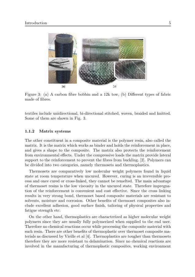
Figure 3: (a) A carbon fibre bobbin and a 12k tow, (b) Different types of fabricmade of fibres.
textiles include unidirectional, bi-directional stitched, woven, braided and knitted.Some of them are shown in Fig. 3.
1.1.2 Matrix systems
The other constituent in a composite material is the polymer resin, also called thematrix. It is the matrix which works as binder and holds the reinforcement in place,and gives a shape to the composite. The matrix also protects the reinforcementfrom environmental effects. Under the compressive loads the matrix provide lateralsupport to the reinforcement to prevent the fibres from buckling. [2]. Polymers canbe divided into two categories, namely thermosets and thermoplastics.Thermosets are comparatively low molecular weight polymers found in liquid
state at room temperature when uncured. However, curing is an irreversible pro-cess and once cured or cross-linked, they cannot be remelted. The main advantageof thermoset resins is the low viscosity in the uncured state. Therefore impregna-tion of the reinforcement is convenient and cost effective. Since the cross linkingresults in very strong bond, thermoset based composite materials are resistant tosolvents, moisture and corrosion. Other benefits of thermoset composites also in-clude excellent adhesion, good surface finish, tailoring of physical properties andfatigue strength etc.
On the other hand, thermoplastics are characterized as higher molecular weightpolymers since they are usually fully polymerized when supplied to the end user.Therefore no chemical reactions occur while processing the composite material withsuch resin. There are other benefits of thermoplastic over thermoset composite ma-terials as discussed by Vieille et al [4]. Thermoplastics are tougher than thermosetstherefore they are more resistant to delamination. Since no chemical reactions areinvolved in the manufacturing of thermoplastic composites, working environment
6 Mohammad Waseem Tahir
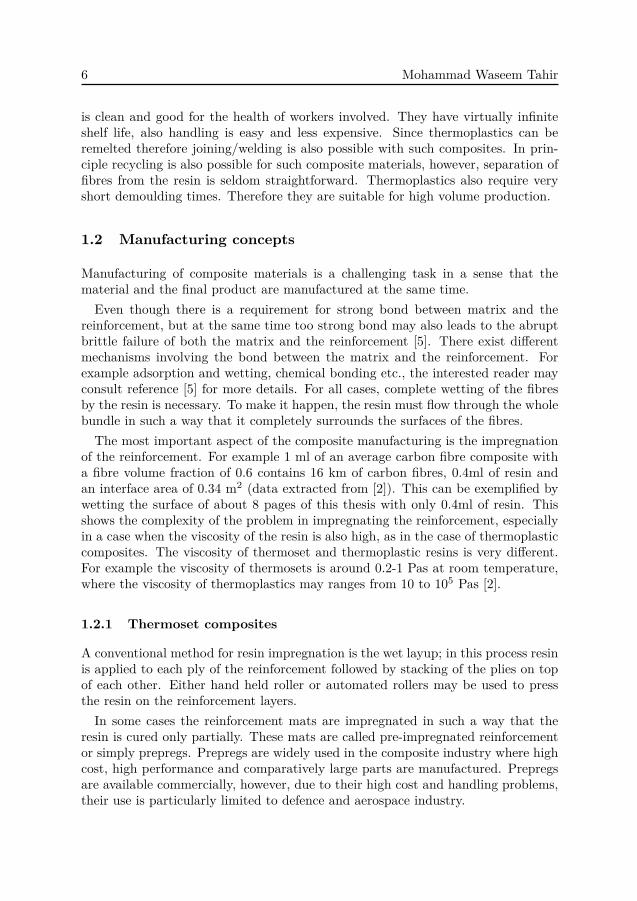
is clean and good for the health of workers involved. They have virtually infiniteshelf life, also handling is easy and less expensive. Since thermoplastics can beremelted therefore joining/welding is also possible with such composites. In prin-ciple recycling is also possible for such composite materials, however, separation offibres from the resin is seldom straightforward. Thermoplastics also require veryshort demoulding times. Therefore they are suitable for high volume production.
1.2 Manufacturing concepts
Manufacturing of composite materials is a challenging task in a sense that thematerial and the final product are manufactured at the same time.Even though there is a requirement for strong bond between matrix and the
reinforcement, but at the same time too strong bond may also leads to the abruptbrittle failure of both the matrix and the reinforcement [5]. There exist differentmechanisms involving the bond between the matrix and the reinforcement. Forexample adsorption and wetting, chemical bonding etc., the interested reader mayconsult reference [5] for more details. For all cases, complete wetting of the fibresby the resin is necessary. To make it happen, the resin must flow through the wholebundle in such a way that it completely surrounds the surfaces of the fibres.
The most important aspect of the composite manufacturing is the impregnationof the reinforcement. For example 1 ml of an average carbon fibre composite witha fibre volume fraction of 0.6 contains 16 km of carbon fibres, 0.4ml of resin andan interface area of 0.34 m2 (data extracted from [2]). This can be exemplified bywetting the surface of about 8 pages of this thesis with only 0.4ml of resin. Thisshows the complexity of the problem in impregnating the reinforcement, especiallyin a case when the viscosity of the resin is also high, as in the case of thermoplasticcomposites. The viscosity of thermoset and thermoplastic resins is very different.For example the viscosity of thermosets is around 0.2-1 Pas at room temperature,where the viscosity of thermoplastics may ranges from 10 to 105 Pas [2].
1.2.1 Thermoset composites
A conventional method for resin impregnation is the wet layup; in this process resinis applied to each ply of the reinforcement followed by stacking of the plies on topof each other. Either hand held roller or automated rollers may be used to pressthe resin on the reinforcement layers.In some cases the reinforcement mats are impregnated in such a way that the
resin is cured only partially. These mats are called pre-impregnated reinforcementor simply prepregs. Prepregs are widely used in the composite industry where highcost, high performance and comparatively large parts are manufactured. Prepregsare available commercially, however, due to their high cost and handling problems,their use is particularly limited to defence and aerospace industry.

Introduction 7
Another method for manufacturing of composite structures is liquid compositemoulding (LCM) which is extensively used in civil, automotive and aerospace in-dustry for manufacturing of thermoset composite parts. Various types of LCM
Figure 4: Schematic diagram of an RTM process [2].
include Resin Transfer Moulding (RTM), Vacuum Assisted Resin Transfer Mould-ing (VARTM) and Structural Reaction Injection Moulding (SRIM). These are ef-ficient manufacturing processes characterized by low volatile organic compoundsand minimum scrap rate. Good surface finish on both sides of the parts, very gooddimensional tolerances and low tooling cost are some of the characteristics of theseprocesses. In an RTM process, the impregnation is carried out in a closed mould.Dry reinforcement is placed in a mould, afterwards it is impregnated with ther-moset resin. A schematic of an RTM process, redrawn from [2] is shown in Fig. 4.This process is very well suited for the impregnation of the preforms1.
1.2.2 Thermoplastic composites
Even though thermoplastic composites have been in the market for a long time, theycould not find much attraction in the industry in comparison to their thermosetcounterparts. The main reason is the high viscosity of thermoplastic resins whichmakes it difficult to achieve good impregnation and wetting of the reinforcement.Thermoplastic composite materials can also be manufactured in various ways, how-ever, there is still no widely accepted commercial method. Some of the manufactur-ing processes for thermoplastic composites are liquid moulding, injection moulding,compression moulding and powder impregnation. Liquid moulding process is the
1preform is the near net shape of the product made of only the reinforcement, See Fig 11.
8 Mohammad Waseem Tahir
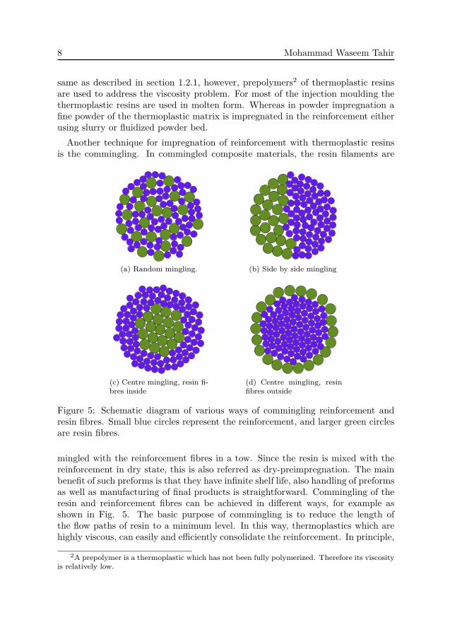
same as described in section 1.2.1, however, prepolymers2 of thermoplastic resinsare used to address the viscosity problem. For most of the injection moulding thethermoplastic resins are used in molten form. Whereas in powder impregnation afine powder of the thermoplastic matrix is impregnated in the reinforcement eitherusing slurry or fluidized powder bed.Another technique for impregnation of reinforcement with thermoplastic resins
is the commingling. In commingled composite materials, the resin filaments are
(a) Random mingling. (b) Side by side mingling
(c) Centre mingling, resin fi-bres inside
(d) Centre mingling, resinfibres outside
Figure 5: Schematic diagram of various ways of commingling reinforcement andresin fibres. Small blue circles represent the reinforcement, and larger green circlesare resin fibres.
mingled with the reinforcement fibres in a tow. Since the resin is mixed with thereinforcement in dry state, this is also referred as dry-preimpregnation. The mainbenefit of such preforms is that they have infinite shelf life, also handling of preformsas well as manufacturing of final products is straightforward. Commingling of theresin and reinforcement fibres can be achieved in different ways, for example asshown in Fig. 5. The basic purpose of commingling is to reduce the length ofthe flow paths of resin to a minimum level. In this way, thermoplastics which arehighly viscous, can easily and efficiently consolidate the reinforcement. In principle,
2A prepolymer is a thermoplastic which has not been fully polymerized. Therefore its viscosityis relatively low.

Introduction 9
the best consolidation and wetting of the reinforcement can be achieved if theconstituent fibres are mingled randomly as shown in Fig. 5a.
Figure 6: Micrograph of a single yarn, showing the mingling of carbon fibres andthe thermoplastic fibres.
Figure 7: Hot press.
A tow of C/PA12 commingled material is analysed under the scanning electronmicroscope (SEM) as shown in Fig. 6. Clearly there is a random mixing of thereinforcement and the resin fibres. The whitish lines in the micrograph are carbonfibres and the larger greyish lines are PA12 resin fibres.
Manufacturing of commingled thermoplastic composites is comparatively simple,and it involves only heat and pressure. However, the manufacturing parameterssuch as pressure, temperature and time may have critical effects on the propertiesof the composite. The process involves heating the preform well above the melting

10 Mohammad Waseem Tahir
Figure 8: Micrograph of a C/PA12, showing consolidation quality.
temperature of the resin followed by the application of a suitable pressure. In gen-eral, vacuum pressure is not enough for such materials, and a hot press is requiredfor this purpose.A hot press and the micrograph of the manufactured part in this press is shown
in Figs. 7 and 8. Very good quality of consolidation can be seen. Since chemicalreactions are not involved, the process is generally considered clean for the workingenvironment. The process cycle time for manufacturing of the commingled com-posite materials can be very short, making this process very efficient. Therefore,such materials are suitable for high volume industry such as automotive.
1.3 2D vs 3D reinforcement
In 2D reinforced composites, the fibres are aligned in a plane with plies of thereinforcement stacked on top of each other. Plies with the fibres aligned alongthe xy plane, are schematically shown in Fig. 9. In order to align the fibres, itis important to ensure that the plies do not slip during the processing. Thereforeit is time consuming resulting in costly product. If the plies are displaced duringmanufacturing it may deteriorate the properties of the final product.
Since the laminated composites lack reinforcement in the through thickness di-rection, they exhibit poor out-of-plane properties. These properties are governed bythe low strength and stiffness of the matrix and the matrix/fibre interface. Brittlenature of thermoset resins also contributes to this problem [6,7].
Another problem with 2D reinforced composites arrives when they are used forstructural profiles, for example T-beam as shown in Fig. 10. For this type ofprofiles, the critical area is the junction laminates as shown in the figure. Even

Introduction 11
Figure 9: Schematic diagram of 2D reinforcement stacking.
though, some type of filler is used to avoid the resin rich region, still the failuregenerally occurs near the filler area (see the figure) because the load transfer in thecurved area generates a strong multi-axial stress field [1].
Figure 10: Schematic diagram of 2D laminated 3D structure, redrawn from [8].
One way to improve the out-of-plane properties is to use a tougher resin, this willbe discussed in section 3.2. Alternatively reinforcement can be added in the throughthickness direction. For example, this can be achieved by employing 3D-weaving.There are different methods for producing 3D-weave as classified by Khokar [9–11].These processes are 2D woven 3D fabrics, 3D-woven 3D fabrics, and Non-interlacing

12 Mohammad Waseem Tahir
Orientating Orthogonally and Binding (Noobing) fabrics, which is also referred as3D orthogonal weave [8].
Figure 11: Dry preforms of 3D-woven textile; courtesy of Biteam AB, Sweden.
In 3D woven 3D fabrics, warp yarns and horizontal and vertical weft yarns aremutually perpendicular. [12]. This is a new technology invented by Khokar [9] inwhich the yarns are fully interlaced. Various kinds of profiles can be woven withthis process as shown in Fig. 11. For more details the interested reader is referredto [8].
Since 3D weaving also includes reinforcement in the through-thickness direction,therefore the composites made of these textiles are likely to have very good out-of-plane properties. In such a process the reinforcement preforms are near net shape ofthe final product. Therefore this process needs less labour time and efforts to man-ufacture a final product. This also reduces the need for post joining processes. Verycomplex geometries can be produced with 3D weaving. However, this also bringsnew challenges to impregnate the preforms efficiently, so that the resin reaches allthe complex regions of the preform.
1.4 Objective and scope
The aim of the current thesis is to characterize the permeability of dual scale fibrousstructures and to analyse the interlaminar properties of composite materials.

Introduction 13
Composites are regarded as the heterogeneous porous medium because both thereinforcement fabric and the tows are porous. In order to characterize the perme-ability of such medium, one of the following two approaches can be used in thenumerical analysis. Either the filaments are added in the geometry or the towsmay be assumed as a porous homogeneous medium containing viscous resistance.
A porous homogenised tow model is benchmarked with the resolved model asa first step because no past study could be found with such a comparison. Theexperimental findings and the numerical results in the past were contradicting aboutthe effect of intra-tow permeability on the overall permeability. Second objectivewas to resolve this issue and to emphasise the level of refinement required for furtherstudy of complex dual scale geometries.
As a second step an experimental study is performed on the novel 3D-wovenpreforms to study how different textile parameters influence the longitudinal per-meability. The effect from three different parameters, namely surface to interiorratio, fibre volume fraction and warp yarn crimp on the permeability of the textile isstudied. The experimental findings are then used to validate the numerical resultsfor the overall permeability of the complex structures. Effect from the inter- andthe intra-tow porosity on the overall permeability is also studied in the numericalsimulations.
As a third step the interlaminar properties of layered composites are studied.Size effects on the interlaminar shear strength of thermoplastic composites are alsoanalysed. It is shown in a finite element analysis that the effect from lack of layerscaling of the composite coupons also contributes in reduction of this property forlarger specimens. The effect of processing on the interlaminar delamination tough-ness of C/PA12 is also studied. The results are also compared with conventional3D stitched thermoset omposites.


Introduction 15
2 Porosity and Permeability
2.1 Porosity
In Fig. 12, three jars are shown, each containing different sizes of pebbles. If wateris poured through these jars, it can flow easily though the glass with the largerpebbles, where it faces the most resistance to flow through the glass containing thesmallest size pebbles. In all of the jars shown in the figure, there exists some openregion which facilitates the flow of fluid through the medium. Such a medium iscalled porous medium. The porosity may be defined as
φ = Vp
Vt, (1)
where, Vp is the volume occupied by voids, and Vt is the total volume of the medium.
Figure 12: Different size of stones showing different scales.
2.2 Permeability
2.2.1 Isotropic medium
Darcy’s law is commonly used to describe the flow through a porous medium. Itstates that for a Newtonian fluid the volumetric flow rate, Q is given by
Q = −κAµ
∆pL, (2)
where A is the cross sectional area of the one-dimensional representation of theflow, ∆p/L is the pressure difference over the length L, µ is the dynamic viscosityof the fluid and κ is the constant of proportionality called as the permeability of

16 Mohammad Waseem Tahir
the porous medium. All the interactions between the fluid and the porous mediumare lumped through the permeability in the Darcy law.The simplest model to predict the permeability of a porous medium can be
expressed as [13]
κ = φ3
τ2A2v
, (3)
where, τ is the tortuosity and Av is the specific surface area defined as the ratioof the interstitial surface area to the bulk volume of the porous medium. Tortuosityis the ratio of the actual path of the fluid particles to the shortest path length in thedirection of flow [14]. Arbitrariness of the tortuosity however, makes it difficult toapply this model [13]. A general relation for the permeability of a porous mediumcan be expressed by Kozeny-Carman relation [13]:
κ = R2
4kφ3
(1− φ)2 , (4)
where, R is the radius of presumingly spherical particles and k is an empirical con-stant often called the Kozeny constant. Eq.(4) was originally derived for granularbeds, similar to the porous medium shown in Fig. 12, therefore the permeabilitywas assumed to be the same in all directions, i.e. isotropic.It is clear from Eq. (4) that even if the jars in Fig. 12 have the same porosities,
they will have very different permeabilities due to the sizes of the pebbles.
2.2.2 Single scale fibrous porous medium
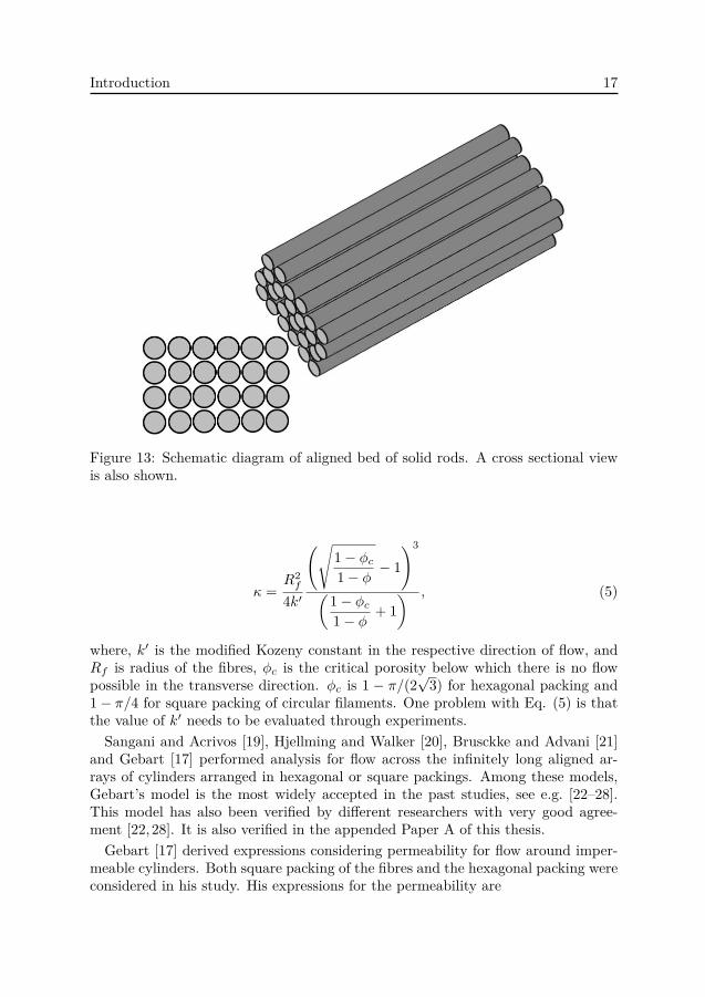
The reinforcement fibres in a tow may be considered as a bed of aligned rods asshown in Fig. 13. As can be seen there is more room for the fluid to flow in thecross sectional view (bottom left of Fig. 13), and even if the cylinders are packedtightly there remains space in between the rods. This means that the permeabilityof such medium may not necessarily be the same in all directions. Therefore, Eq.(4) is not the true representation of the permeability of such media. Remedy to thisdeficiency was initially proposed by Gutowski et al. [15] who used the unidirectionalreinforcements and suggested different Kozeny constants in different directions.
It has also been critically questioned by different researchers if the Kozney con-stant is in fact a constant. It was stated in [16, 17] that the Kozney constant is aweak function of the fibre volume fraction. Another disadvantage with the Kozeny-Carman model is that it predicts non-zero permeability in the transverse directioneven for maximum packing of the fibres, which is not true in practice. Fluid flowthrough the transverse direction can be obstructed completely if the cylinders areperfectly aligned and packed tightly. This problem was also addressed by Gutowskiet al. [18] who suggested a modification to this model by introducing the maximumpacking of the fibres in the model. The following expression was suggested forpermeability
Introduction 17
Figure 13: Schematic diagram of aligned bed of solid rods. A cross sectional viewis also shown.
κ =R2
f
4k′
(√1− φc
1− φ − 1)3
(1− φc
1− φ + 1) , (5)
where, k′ is the modified Kozeny constant in the respective direction of flow, andRf is radius of the fibres, φc is the critical porosity below which there is no flowpossible in the transverse direction. φc is 1 − π/(2
√3) for hexagonal packing and
1− π/4 for square packing of circular filaments. One problem with Eq. (5) is thatthe value of k′ needs to be evaluated through experiments.Sangani and Acrivos [19], Hjellming and Walker [20], Brusckke and Advani [21]
and Gebart [17] performed analysis for flow across the infinitely long aligned ar-rays of cylinders arranged in hexagonal or square packings. Among these models,Gebart’s model is the most widely accepted in the past studies, see e.g. [22–28].This model has also been verified by different researchers with very good agree-ment [22,28]. It is also verified in the appended Paper A of this thesis.
Gebart [17] derived expressions considering permeability for flow around imper-meable cylinders. Both square packing of the fibres and the hexagonal packing wereconsidered in his study. His expressions for the permeability are

18 Mohammad Waseem Tahir
κ⊥ = C
(√1− φc
1− φ − 1)2.5
R2f , (6)
κ‖ =8R2
f
c
φ3
(1− φ)2 , (7)
where, C is a constant depending on the type of packing of the filaments. Gebart’srelations are different than the Kozeny-Carman and Gutowski relations in that theydo not include empirical constants.
2.2.3 Dual scale porous medium
The models presented in [15, 17, 18, 21, 22] were single scale models, because re-inforcements were considered to be distributed homogeneously in the medium asshown in Fig. 14a. However, as described in section 1.1.1, due to the handling
Figure 14: Homogeneous and heterogeneous arrangement of reinforcement.
reasons fibres are commonly supplied in tows which are then arranged in differentkinds of mats of reinforcement as shown in Fig. 3.In Fig. 14b an ideal representation of arrangement of tows is shown in a uni-
directional mat. If hexagonal arrangement of carbon fibres with diameter 7µm isassumed, then for maximum packing (vf )=0.91, the size of a tow will be 0.17-0.35mm for 3k or 12k tow respectively. This means that the flow through the matmay be considered at two different length scales. Therefore, even if the porositiesare the same, the permeability will be very different inside and outside the tows.The porosity inside the tow is referred as the intra-tow porosity (φt), where theporosity in between the tows is called as the inter-tow porosity (φs). The overallporosity (φo) of such a medium is then
φo = φt + φs − φtφs, (8)
Similarly the permeability inside the tows is referred as the intra-tow permeability(κt). The permeability through the tows is called the inter-tow permeability (κs).
Introduction 19
Where the permeability of the overall medium is called the overall permeability (κo).Initially Phelan [29] introduced the concept of inter and intra-tow flow. Later therewas extensive work done by different researchers in this field.
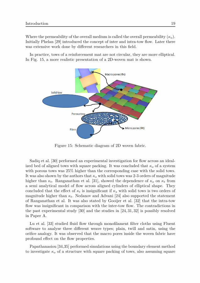
In practice, tows of a reinforcement mat are not circular, they are more elliptical.In Fig. 15, a more realistic presentation of a 2D-woven mat is shown.
Figure 15: Schematic diagram of 2D woven fabric.
Sadiq et al. [30] performed an experimental investigation for flow across an ideal-ized bed of aligned tows with square packing. It was concluded that κo of a systemwith porous tows was 25% higher than the corresponding case with the solid tows.It was also shown by the authors that κs with solid tows was 2-3 orders of magnitudehigher than κt. Ranganathan et al. [31], showed the dependence of κo on κt froma semi analytical model of flow across aligned cylinders of elliptical shape. Theyconcluded that the effect of κt is insignificant if κs with solid tows is two orders ofmagnitude higher than κt. Nedanov and Advani [24] also supported the statementof Ranganathan et al. It was also stated by Gooijer et al. [32] that the intra-towflow was insignificant in comparison with the inter-tow flow. The contradictions inthe past experimental study [30] and the studies in [24, 31, 32] is possibly resolvedin Paper A.
Lu et al. [33] studied fluid flow through monofilament filter cloths using Fluentsoftware to analyse three different weave types; plain, twill and satin, using theorifice analogy. It was observed that the macro pores inside the woven fabric haveprofound effect on the flow properties.
Papathanasiou [34,35] performed simulations using the boundary element methodto investigate κo of a structure with square packing of tows, also assuming square

20 Mohammad Waseem Tahir
packing of fibres inside the tows. An expression was presented
κo = κs
(1 + α
(κs
κt
)n−1.5), (9)
where α and n were estimated using curve fitting. The findings in Paper A are alsocompared with the past studies [17, 35] and very good agreement is found. Also,these findings are in line with the past studies [24,31,32]. It is however found thatthe findings in Paper A are not in line with [30]. However, it is further presentedthat in [30] the permeabilities for solid and porous tows were not compared atsame porosities. Taking that into account, the results from Paper A and all thepast studies are well in agreement.In order to model the flow through the dual scale fibre structure, two approaches
are commonly adopted
• filaments are physically modelled in the geometry, referred to as resolvedmodels,
• tows are considered as homogenized porous media and the influence of thefilaments inside the tows is represented by a parameter κt.
Both approaches are presented in Paper A, and the refinement required for mod-elling the permeability of a dual scale structure is emphasised for future modellingof complex geometries.
2.3 Permeability of 3D-reinforced composites
Permeability can either be estimated experimentally or through numerical compu-tations. For 2D mats of reinforcement, there exist established methods to com-pute the permeability experimentally. However, there is no established method formeasuring the permeability of 3D structures. There are also great variations inthe experimentally measured permeabilities reported in the literature. Parnas etal. [36] attributed the discrepancy to the use of different fabric architectures in thestudies.Ngo and Tamma [23,25], used a unit cell of woven preform to predict the perme-
ability of a 3D woven structure. They employed Gebart relations [17] for the inputpermeability inside the tows. Nabovati et al. [37], investigated a flow through ahighly idealized 3D multifilament structure of dual length scale. Therefore φt em-ployed in their models was rather high (0.64− 0.80). Imagine a complex 3D textilearchitecture as shown in Fig. 16. It is impractical and computationally very costlyto use a resolved modelling technique for such a model.In Paper B, the permeability of a novel 3D architecture is measured experimen-
tally. The same architecture is then analysed using computational fluid dynam-ics (CFD) modelling in Paper C to characterize the permeability of the material

Introduction 21
Vertical Weft
Warp
Horizontal Weft
X
Z
Y
Z
XY
X Y
Z
Figure 16: Model of a 3D woven textile fabric, box with black border is the RVE.Courtesy of Hallström and Stig.
numerically. In the past studies, the geometries analysed were of highly ideal-ized nature in a sense that they utilize only circular or perfect elliptical shapesfor computation of the permeability. With such geometries, it is not possible toachieve real fibre volume fractions. In practice, the tows of a composite materialare irregular elliptical shape. For 2D/3D woven preforms, the cross sections of thetows may become very irregular, especially at the crossovers. Taking this fact intoconsideration, a novel 3D-woven geometry is utilized for the CFD analysis.Due to full interlacing of the tows in 3D-woven preforms, the cross section as well
as the direction of the tows vary between different positions. Models containing thedetailed information of the input κt were initially developed. Comparison of thesemodels with the models containing coarser details of input κt however show nolarge difference in the overall permeability. A full tensor of the permeability is alsocomputed for the models with different φs, it is presented in Paper C.Flow path-lines coloured by velocity in the flow direction are presented in fig. 18
showing the complexity of the flow for such geometries.

22 Mohammad Waseem Tahir
(a) UC with tows (b) Region of resin fill in UC
Figure 17: UC for the 3D model with φs = 0.2.
Figure 18: Path-lines coloured by the velocity along their flow direction, φs = 0.3.

Introduction 23
3 Interlaminar properties of composites
Interlaminar failure is very common in the laminated composite structures. Theout-of-plane loads which leads to the interlaminar stresses in laminated structuresand may cause delamination are shown in Fig. 19.
Figure 19: Various out-of-plane loads which may lead to delamination in the lami-nated structures. Curtsey of Professor Tonny Nyman and Professor Dan Zenkert.
3.1 Interlaminar shear properties-size effects
The inter-laminar shear strength (ILSS) is an important property of a compositewhen subjected to out-of-plane loads. A short beam shear (SBS) test is usuallyemployed to determine the ILSS of a composite material. The complexity of theinternal stresses makes it difficult to relate the results obtained from this method toone single property. However, since interlaminar shear strength is dominating, thismethod is still valid for comparison and quality assurance [38]. Different failuremodes can occur in a SBS test. These failure modes are discussed in detail byDaniels et al. [39] and are:
• interlaminar shear failure• tensile failure• compressive damage under the top roller

24 Mohammad Waseem Tahir
• permanent plastic deformation or compression jamming
ILSS may be considered valid if the specimen fail in an interlaminar shear failuremode. There may also be combination of theses failures in the SBS test as shownin Fig. 20.
Figure 20: Schematic diagram of failure modes in SBS test, redrawn from [40].
Commonly the classical beam theory is used to compute the ILSS where it isassumed that the shear stress field is of parabolic nature, with maximum stress atthe mid plane of the specimen. However, due to non-linear nature of stresses andinhomogeneous features of the composite material, it is more likely that delami-nation cracks distribute over the thickness. The stress concentration near the toproller as pointed by Cui et al [41], and in Paper D could also initiate failure. Dueto these reasons the ILSS obtained through this method is generally referred asapparent ILSS.
Size effect of the structure on its nominal strength is an old problem [42]. For thethermoset composites, size effects are prominent since these materials present brittlebehaviour [43]. While there are numerous past studies about the size effects ofthermosets, few are found for the thermoplastic composite materials. In this thesiswork size effects are studied on the ILSS of commingled thermoplastic compositematerials C/PA12 and carbon-polyethylene terephthalate (C/PET).
In the past studies, size effects in composite structures were considered by scal-ing the outer dimensions of the specimens. One would assume that when having

Introduction 25
Figure 21: Schematic diagram of true scaling of layers in a lamina.
the right failure mode, all specimens would result in the same ILSS provided nostatistical scaling effects are present. However, layered materials can not be fullyscaled experimentally due to fixed layer thickness. Therefore finite element (FE)simulations are performed. Layer scaling in a composite coupon is exemplifiedschematically in Fig. 21. It is found that the scaling effects, which in the pasthave been described as statistical only, may also be influenced by the lack of layerthickness scaling.
3.2 Interlaminar fracture toughness
As stated in section 1.3, conventional thermoset composite materials have poorout-of-plane properties. Therefore delamination is a common problem for such ma-terials. As reported in the past studies, the mode I critical strain energy releaserate (GIc) of conventional thermoset based composites is 0.2-0.4 kJ/m2 [44]. Thebrittle nature of thermoset resins is one of the main reasons for proneness to delam-ination of these materials [6, 7]. In the past, various ways to improve the through-thickness properties of conventional composite materials have been suggested. Forexample use of additives such as rubber based tougheners to increase the toughnessof the resin [6, 45], others also used nano-particles for this purpose [46–48].Through-thickness mechanical properties of composite materials can also be im-
proved by use of stitched reinforcement in the out-of-plane direction or by Z-pinning [49]. Many studies have reported that the interlaminar toughness improvedto a great extent by using this method [50, 51]. However, there are some studies,which show that the stitching also degrades the in-plane properties of a compositematerial [52–54]. The pros and cons of stitched composites are briefly discussedby Mourtiz et al. [55]. Alternatively, 3D woven and braiding are recently emergingtechniques in the composite field.
One solution to overcome the problem of delamination is to use a tougher resine.g a thermoplastic. In Paper E, the delamination properties of commingled ther-moplastic composites are analysed and a comparison is also made with the stitch-reinforced thermoset composites.
26 Mohammad Waseem Tahir
3.2.1 Delamination in composites
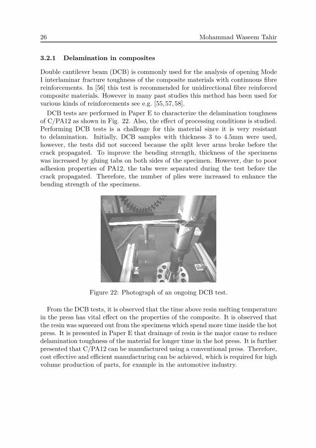
Double cantilever beam (DCB) is commonly used for the analysis of opening ModeI interlaminar fracture toughness of the composite materials with continuous fibrereinforcements. In [56] this test is recommended for unidirectional fibre reinforcedcomposite materials. However in many past studies this method has been used forvarious kinds of reinforcements see e.g. [55, 57,58].DCB tests are performed in Paper E to characterize the delamination toughness
of C/PA12 as shown in Fig. 22. Also, the effect of processing conditions is studied.Performing DCB tests is a challenge for this material since it is very resistantto delamination. Initially, DCB samples with thickness 3 to 4.5mm were used,however, the tests did not succeed because the split lever arms broke before thecrack propagated. To improve the bending strength, thickness of the specimenswas increased by gluing tabs on both sides of the specimen. However, due to pooradhesion properties of PA12, the tabs were separated during the test before thecrack propagated. Therefore, the number of plies were increased to enhance thebending strength of the specimens.
Figure 22: Photograph of an ongoing DCB test.
From the DCB tests, it is observed that the time above resin melting temperaturein the press has vital effect on the properties of the composite. It is observed thatthe resin was squeezed out from the specimens which spend more time inside the hotpress. It is presented in Paper E that drainage of resin is the major cause to reducedelamination toughness of the material for longer time in the hot press. It is furtherpresented that C/PA12 can be manufactured using a conventional press. Therefore,cost effective and efficient manufacturing can be achieved, which is required for highvolume production of parts, for example in the automotive industry.

Introduction 27
4 Contribution to the field
A porous homogenized tow model was benchmarked with the resolved model whichwas not presented in the past. A very clear picture of the effect of the inter- andintra-tow porosity on the overall permeability of the dual scale porous structureis presented confirming some conclusions and clarifying some of contradictions inprevious work.The permeability of a novel 3D structure is studied experimentally. The effect
on the overall permeability is studied from three parameters; surface to interiorratio of the yarns, fibre volume fraction and warp yarn crimp. The fibre volumefraction is varied in three different ways and the effect on the overall permeabilityis studied. In this way homogenized and localized effects of the inter-tow porosityon the overall permeability are studied.
The porous homogenized tow model is used for estimating the overall perme-ability of complex 3D-woven structures. The models used in the study are noveland near to the real 3D-woven geometry in a sense that full interlacing and localshape variations of the tows are taken into account. Such analysis of 3D complexstructures were not presented before. This method can be used for estimating thepermeability of many types of complex dual scale porous structures.
The interlaminar shear strength of two kinds of commingled thermoplastic com-posite materials is characterized experimentally. The statistical size effects andthe layer scaling effects are studied separately which would be helpful for betterunderstanding of such effects.
It is shown that a hot press - which seems to be considered necessary for ther-moplastic composites manufacturing - can be replaced with a conventional coldpress and even provide better delamination toughness. Such a material can bringrevolutionary changes in mass production of composite manufacturing. The su-perior delamination toughness presented for commingled thermoplastic composite(C/PA12) will be helpful in manufacturing better quality of products.

Introduction 29
5 Summery of appended papers
Paper A
The effect of various parameters on the overall permeability of a two dimensionaldual scale fibrous structure is studied employing computational fluid dynamics.The model is benchmarked with previous studies using both solid tow and poroushomogenized tow models. Porous homogenized tow models are also benchmarkedwith the resolved model. Very good agreement is found with previous studies andthe resolved model.The simulations suggests that the intra-tow porosity has an insignificant influence
on the overall permeability, whereas inter-tow porosity has very strong effect, inrespect to the real composite structures, for which the size of the fibres is two ordersof magnitude lower than the size of the tows. A contradiction found among thepast studies is also resolved in this paper.
Paper B
Experimental measurements of the permeability of fully interlaced 3D-woven carbonfibre preforms are performed. The effect on the permeability from three differentparameters is studied by altering the architecture of the woven preforms and varyingthe fibre volume fraction. The influence from the geometrically different surfacelayers of the woven preforms, fibre volume fraction and warp yarn crimp on thepermeability of the textiles is studied. It is concluded that the effect is not consistentin terms of the fibre volume fraction alone, but depends on how it is varied.
Paper C
Various modelling aspects of the permeability of 3D-woven textile preforms arestudied using computational fluid dynamics. It is found that variations in thelocal intra-tow permeability, both in magnitude and direction, have little effecton the overall permeability of the fabric. φs on the other hand proved to have asignificant influence. A complete permeability tensor is also computed for whichthe off-diagonal values of the overall permeability are negligible compared to theprincipal overall permeability. Good agreement is found between the experimentaland numerical results.
Paper D
Size effects for C/PA12 and C/PET thermoplastic composite materials are inves-tigated. In the present study along with the statistical size effects performed ex-perimentally, two types of scaling are considered using finite element analysis. It is

30 Mohammad Waseem Tahir
presented that the size effects are partly due to volumetric effect and partly due tolack of layer scaling in the layered composite coupons.
Paper E
The interlaminar delamination properties of carbon/PA12 are evaluated using adouble cantilever beam test method. The effect of consolidation time on the in-terlaminar properties of this material was also studied. It was found that theconsolidation time has prominent effect on the interlaminar properties. It is fur-ther presented that the thermoplastic material used in this study have 1.5 timeshigher interlaminar fracture toughness than the stitched thermoset composites.

Introduction 31
6 Future work
Resin transfer moulding (RTM) process optimization and the numerical simulationsfor this process for the complex 3D-woven preform is the next step to be done.The work initiated on thermoplastic commingled composite materials was ini-
tially intended for studying 3D-woven materials, especially addressing the delam-ination properties. However, it was found that there was not much work done on2D fabrics and their properties in that respect. In future, 3D-woven thermoplasticcomposites should also be studied.
In this study it is shown that C/PA12 has superior delamination properties.Combined with short manufacturing time and replacing the hot press with conven-tional cold press, these materials can be very suitable for mass volume productions.However, cost estimation and assessment of the availability of such materials is awork to be done in the future. One of the major benefits of thermoplastics is thatthey can be welded. This is also a topic for future studies in this field. Extrusionfor thermoplastic composites is also an attractive manufacturing process, this canalso be a topic for future work.


Introduction 33
Bibliography
[1] L. Tong, A. P. Mouritz, and M. K. Bannister. Chapter 1 - introduction. InLiyong Tong, Adrian P. Mouritz, and Michael K. Bannister, editors, 3D FibreReinforced Polymer Composites, pages 1 – 12. Elsevier Science, Oxford, 2002.
[2] B. T. Åström. Manufacturing of Polymer Composites. Chapman and Hall,1997.
[3] B. Ley. Measuring the diameter of a human hair using a laser. Website:StemAK. (accessed on 01-05-2014) <Url> http://stemak.org/how-tos/.
[4] B. Vieille, V. M. Casado, and C. Bouvet. About the impact behavior of woven-ply carbon fiber-reinforced thermoplastic- and thermosetting-composites: Acomparative study. Composite Structures, 101(0):9 – 21, 2013.
[5] S. M. Lee. Handbook of Composite Reinforcements, chapter Interfacial Analy-sis, pages 283–298. John Wiley and sons, 1993.
[6] A. J. Kinloch, D. L. Maxwell, and R. J Young. The fracture of hybrid-particulate composites. Journal of Materials Science, 20(11):4169–4184, 1985.
[7] N. Sela and O. Ishai. Interlaminar fracture toughness and toughening of lam-inated composite materials: a review. Composites, 20(5):423 – 435, 1989.
[8] F. Stig. 3D-woven Reinforcement in Composites. PhD thesis, KTH, RoyalInstitiute of Technology, 2012.
[9] N. Khokar. 3d fabric-forming processes: Distinguishing between 2d-weaving,3d-weaving and an unspecified non-interlacing process. Journal of Text. Inst.,87 Part 1, No. 1:97–106, 1996.
[10] N. Khokar. 3d-weaving: Theory and practice. Journal of Text. Inst., 92 Part1, No. 2:193–207, 2001.
[11] N. Khokar. Noobing: A nonwoven 3d fabric-forming process explained. Journalof Text. Inst., 93 Part 1, No. 1:52–74, 2002.
[12] N. Khokar. 3D-Weaving and noobing: Characterization of interlaced and non-interlaced 3D fabric forming principles. PhD thesis, Chalmers University ofTechnology, 1997.
[13] T. G. Gutowski. Advance Composite Manufacturing. John Wiley and sons,Inc., 1997.
[14] A. Ghassemi and A. Pak. Pore scale study of permeability and tortuosity forflow through particulate media using lattice boltzmann method. InternationalJournal for Numerical and Analytical Methods in Geomechanics, 35(8):886–901, 2011.

34 Mohammad Waseem Tahir
[15] T. G. Gutowski, T. Morigaki, and Z. Cai. The consolidation of laminatecomposites. Journal of Composite Materials, 21:172–189, 1986.
[16] J. G. Williams, C. E. M. Morris, and B. C. Ennis. Liquid flow through alignedfiber beds. Polymer Engineering & Science, 14(6):413–419, 1974.
[17] B. R. Gebart. Permeability of unidirectional reinforcement for rtm. Journalof Composite Materials, 26(8):1100–1134, 1990.
[18] T.G. Gutowski, Z. Gai, S. Bauer, and D. Boucher. Consolidation expermentsfor laminate composites. Journal of Compo, 21:650–669, 1987.
[19] A. S. Sangani and A. Acrivos. Slow flow past periodic arrays of cylinderswith application to heat transfer. International Journal of Multiphase Flow,8(3):193 – 206, 1982.
[20] L. N. Hjellming and J. S. Walker. Motion of comtinuouw fibers through anewtonian resin for high fiber volume fraction. Journal of Composite, 24:853–878, 1990.
[21] M. V. Bruschke and S. G. Advani. Flow of generalized newtonian fluids acrossa periodic array of cylinders. Journal of reheology, 37(3):479–497, 1993.
[22] T. S. Lundström. Micromechanical analysis of permeability of a fibrous pre-form. SICOMP Technical Report, 91-001, 1991.
[23] N. D. Ngo and K. K. Tamma. Microscale permeability predictions of porousfibrous media. International Journal of Heat and Mass Transfer, 44(16):3135– 3145, 2001.
[24] P. B. Nedanov and S. G. Advani. Numerical computation of the fiber pre-form permeability tensor by the homogenization method. Polymer Composites,23(5):758–770, 2002.
[25] N. D. Ngo and K. K. Tamma. Complex three-dimensional microstructuralpermeability prediction of porous fibrous media with and without compaction.International Journal for Numerical Methods in Engineering, 60:1741–1757,2004.
[26] Q. Wang, B. Maze, H. V. Tafreshi, and B. Pourdeyhimi. A note on permeabil-ity simulation of multifilament woven fabrics. Chemical Engineering Science,61(24):8085 – 8088, 2006.
[27] C. C. Wong, A. C. Long, M. Sherburn, F. Robitaille, P. Harrison, and C. D.Rudd. Comparisons of novel and efficient approaches for permeability predic-tion based on the fabric architecture. Composites Part A: Applied Science andManufacturing, 37(6):847 – 857, 2006.
Introduction 35
[28] A. Nabovati, E. W. Llewellin, and C. M. S. Antonio. A general model forthe permeability of fibrous porous media based on fluid flow simulations us-ing the lattice boltzmann method. Composites Part A: Applied Science andManufacturing, 40(6-7):860 – 869, 2009.
[29] F. R. Phelan. Modeling of microscale flow in fibrous porous media. In Ad-vanced Composite Materials: New Developments and applications, Conferenceproceedings, Detroit, USA,, 1991.
[30] T. A. K. Sadiq, S. G. Advani, and R. S. Parnas. Experimental investigation oftransverse flow through aligned cylinders. International Journal of MultiphaseFlow, 21(5):755 – 774, 1995.
[31] S. Ranganathan, F. R. Phelan, and S. G. Advani. A generalized model forthe transverse fluid permeability in unidirectional fibrous media. PolymerComposites, 17(2):222–230, 1996.
[32] H. Gooijer, M. M. C. G. Warmoeskerken, and W. J. Groot. Flow resistanceof textile materials: Part ii: Multifilament fabrics. Textile Research Journal,73(6):480–484, 2003.
[33] W. M. Lu, K. L. Tung, and K. L. Tung. Fluid flow through basic weaves ofmonofilament filter cloth. Textile Research, 66(5):311–323, 1996.
[34] T. D. Papathanasiou. A structure-oriented micromechanical model for viscousflow through square arrays of fiber clusters. Composites Science and Technol-ogy, 56(9):1055–1069, 1996.
[35] T. D. Papathanasiou. Flow across structured fiber buldles: a dimensionlesscorrelation. International journal of multiphase flow, 27:1451–1461, 2001.
[36] R. S. Parnas, J. G. Howard, T. L. Luce, and S. G. Advani. Permeabilitycharacterization. part 1: A proposed standard reference fabric for permeability.Polymer Composites, 16(6):429–445, 1995.
[37] A. Nabovati, E. W. Llewellin, and C. M. S. Antonio. Through thickness per-meability prediction of three-dimensional multifilament woven fabrics. Com-posites, 41:453–463, 2010.
[38] ASTM Standard D 2344/D 2344M - 00 (Reapproved 2006), "Standard TestMethod for Short-Beam Strength of Polymer Matrix Composite Materialsand Their Laminates", ASTM International, West Conshohocken, PA 2006,DOI:10.1520/D2344-D2344M-00R06.
[39] B. K. Daniels, N. K. Harakas, and R. C. Jackson. Short beam shear tests ofgraphite fiber composites. Fibre Science and Technology, 3(3):187 – 208, 1971.

36 Mohammad Waseem Tahir
[40] K. Padmanabhan and Kishore. Interlaminar shear of woven fabric kevlar-epoxy composites in three-point loading. Materials Science and Engineering:A, 197(1):113 – 118, 1995.
[41] W. C. Cui and M. R. Wisnom. Contact finite element analysis of three- andfour-point short-beam bending of unidirectional composites. Composites Sci-ence and Technology, 45(4):323 – 334, 1992.
[42] Z. P. Bazant and E.P Chen. Scaling of structural failure. Applied MechanicsReviews, 50(10):593–627, 1997.
[43] M.R. Wisnom. Size effects in the testing of fibre-composite materials. Com-posites Science and Technology, 59(13):1937 – 1957, 1999.
[44] V. Tamuzs, S. Tarasovs, and U. Vilks. Delamination properties oftranslaminar-reinforced composites. Composites Science and Technology,63(10):1423 – 1431, 2003.
[45] M. R. Khan, H. Mahfuz, T. Leventouri, V. K. Rangari, and A. Kyriacou.Enhancing toughness of low-density polyethylene filaments through infusion ofmultiwalled carbon nanotubes and ultrahigh molecular weight polyethylene.Polymer Engineering & Science, 51(4):654–662, 2011.
[46] P. R Thakre, D. C. Lagoudas, J. C. Riddick, T. S. Gatesand, S. J. V. Frankland,J. G. Ratcliffe, J. Zhu, and E. V. Barrera. Investigation of the effect of singlewall carbon nanotubes on interlaminar fracture toughness of woven carbonfiber-epoxy composites. Journal of Composite Materials, 45(10):1091–1107,2011.
[47] Y. Tang, L. Ye, Z. Zhang, and K. Friedrich. Interlaminar fracture tough-ness and CAI strength of fibre-reinforced composites with nanotubes-a review.Composites Science and Technology, 86(0):26 – 37, 2013.
[48] N. T. Phong, M. H. Gabr, K. Okubo, B. Chuong, and T. Fujii. Improvement inthe mechanical performances of carbon fiber/epoxy composite with addition ofnano-(polyvinyl alcohol) fibers. Composite Structures, 99(0):380 – 387, 2013.
[49] A. J. Brunner, B. R. K. Blackman, and P. Davies. A status report on delamina-tion resistance testing of polymerÂĂmatrix composites. Engineering FractureMechanics, 75(9):2779 – 2794, 2008.
[50] R. Velmurugan and S. Solaimurugan. Improvements in mode i inter-laminar fracture toughness and in-plane mechanical properties of stitchedglass/polyester composites. Composites Science and Technology, 67(1):61 –69, 2007.

Introduction 37
[51] S. Solaimurugan and R. Velmurugan. Influence of in-plane fibre orientation onmode i interlaminar fracture toughness of stitched glass/polyester composites.Composites Science and Technology, 68:1742 – 1752, 2008.
[52] R. Velmurugan, N.K. Gupta, S. Solaimurugan, and A. Elayaperumal. Theeffect of stitching on FRP cylindrical shells under axial compression. Interna-tional Journal of Impact Engineering, 30:923 – 938, 2004.
[53] M. Z. Shah Khan and A. P. Mouritz. Fatigue behaviour of stitched {GRP}laminates. Composites Science and Technology, 56(6):695 – 701, 1996.
[54] M. Grassi and X. Zhang. Finite element analyses of mode i interlaminar de-lamination in z-fibre reinforced composite laminates. Composites Science andTechnology, 63(12):1815 – 1832, 2003.
[55] A. P. Mouritz, M. K. Bannister, P. J. Falzon, and K. H. Leong. Review of ap-plications for advanced three-dimensional fibre textile composites. CompositesPart A: Applied Science and Manufacturing, 30(12):1445 – 1461, 1999.
[56] ASTM Standard D 5528, "Standard Test Method for Mode I Interlaminar Frac-ture Toughness of Unidirectional Fiber-Reinforced Polymer Matrix Compos-ites", ASTM International, West Conshohocken, DOI: 10.1520/D5528.
[57] S. P. Blake, K. A. Berube, and R. A. Lopez-Anido. Interlaminar fracturetoughness of woven e-glass fabric composites. Journal of Composite Materials,46(13):1583–1592, 2012.
[58] D. T. Fishpool, A. Rezai, D. Baker, S. L. Ogin, and P. A. Smith. Interlami-nar toughness characterisation of 3d woven carbon fibre composites. Plastics,Rubber and Composites, 42(3):108–114, 2013.


Part II
Appended papers
39