Dual Rod Cylinder · Dual rod cylinder with guide function suitable for pick & place applications....
71
Dual rod cylinder with guide function suitable for pick & place applications. Series Variations Series Variations Series Variations Series Compact type Basic type With air cushion With end lock Double rod type CXSJ CXS CXS CXS CXSW Bore size (mm) 6 10 15 20 25 32 Axial foot piping (Ball bushing bearing only) (ø6, ø10 only) (Ball bushing bearing only) (ø6 only) P.549 Page P.561 P.571 P.578 P.585 Series CXSJ/CXS Dual Rod Cylinder ø6, ø10, ø15, ø20, ø25, ø32 Clean Series 10- 11- 12- Twice the thrust Non-rotating accuracy ±0.1° Ball bushing bearings and slide bearings are standard for all series. Dimensions for ball bushing bearings and slide bearings are the same. Adjustable stroke range: 0 to –5 mm Work can be mounted on three faces. 535 CX2 CXW CXT CXSJ CXS Individual -X D- -X
Transcript of Dual Rod Cylinder · Dual rod cylinder with guide function suitable for pick & place applications....

Dual rod cylinder with guide function
suitable for pick & place applications.
Series VariationsSeries VariationsSeries Variations
Series
Compact type
Basic type
With air cushion
With end lock
Double rod type
CXSJ
CXS
CXS
CXS
CXSW
Bore size (mm)
6 10 15 20 25 32
Axial foot
piping
(Ball bushing bearing only)(ø6, ø10 only)
(Ball bushing bearing only)(ø6 only)
P.549
Page
P.561
P.571
P.578
P.585
Series CXSJ/CXS
Dual Rod Cylinder
ø6, ø10, ø15, ø20, ø25, ø32
Clean Series
10- 11- 12-
Twice the thrust
Non-rotating accuracy ±0.1°
Ball bushing bearings and slide bearings are standard for all series.Dimensions for ball bushing bearings and slide bearings are the same.
Adjustable stroke range:
0 to –5 mm
Work can be mounted on three faces.
535
CX2
CXW
CXT
CXSJ
CXS
Individual-X�
D-�
-X�

Compact Type Series CXSJ
Auto switch can be installed from 3 directions.
Dimensions/Mass
Symmetric mounting
Axial piping available (ø6, ø10)
Reverse
Width (CXSJ)
Full length
(CXSJ)
Width (CXS) Full length (C
XS)
He
igh
t (C
XS
J)
Hei
ght (
CX
S)
CXSJ
CXS
Reverse mounting mechanism
Reversible
Auto switch
Bolt holder
Mounting bolt
Bolt holder
Since the bolt holder is movable, the mounting bolt does not interfere with the auto switch no matter what direction it is mounted from.
Note) Slide bearing, 20 mm strokes
Bore size
(mm)
ø6
ø10
ø15
ø20
ø25
ø32
13.4
15
19
24
29
37
16
17
20
25
30
38
Dimensions (mm)
32
42
54
62
73
94
37
46
58
64
80
98
42 + Stroke
56 + Stroke
70 + Stroke
84 + Stroke
87 + Stroke
100.5 + Stroke
58.5 + Stroke
72 + Stroke
79 + Stroke
94 + Stroke
96 + Stroke
112 + Stroke
0.057
0.114
0.219
0.371
0.544
1.078
0.095
0.170
0.280
0.440
0.660
1.230
CXS�6
CXS�10
CXS�15
CXS�20
CXS�25
CXS�32
CXSJ�6
CXSJ�10
CXSJ�15
CXSJ�20
CXSJ�25
CXSJ�32
SeriesHeight Width Full length
Mass
(kg)
Note)
Allowable kinetic energy, allowable load, and non-rotating accuracy are equivalent to those of CXS basic type.
536
Clean SeriesClean Series
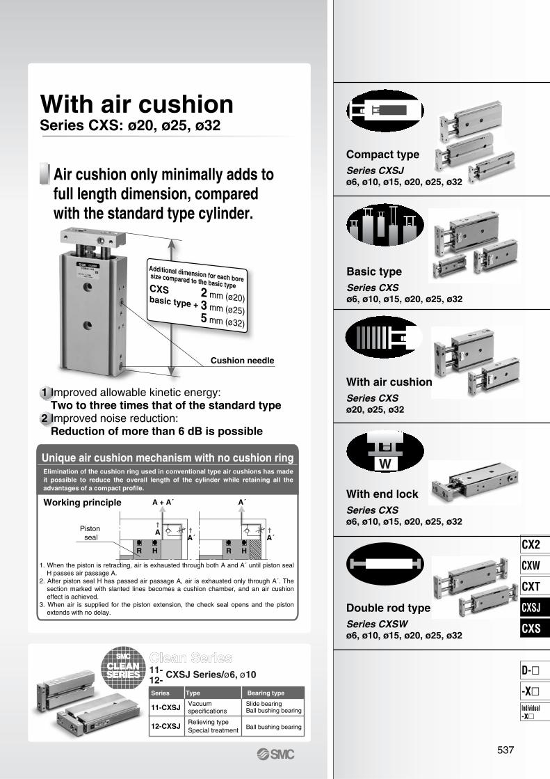
With air cushionSeries CXS: ø20, ø25, ø32
Working principle A + A´
A
R H
Piston seal A´
A´
R H
A´
TypeSeries
11-CXSJ
12-CXSJ
11-12-
CXSJ Series/ø6, ø10
W
Air cushion only minimally adds to
full length dimension, compared
with the standard type cylinder.
Cushion needle
1 Improved allowable kinetic energy: Two to three times that of the standard type
2 Improved noise reduction: Reduction of more than 6 dB is possible
CXSbasic type +
Additional dimension for each bore size compared to the basic type
2 mm (ø20)3 mm (ø25)5 mm (ø32)
Unique air cushion mechanism with no cushion ringElimination of the cushion ring used in conventional type air cushions has made
it possible to reduce the overall length of the cylinder while retaining all the
advantages of a compact profile.
1. When the piston is retracting, air is exhausted through both A and A´ until piston seal H passes air passage A.
2. After piston seal H has passed air passage A, air is exhausted only through A´. The section marked with slanted lines becomes a cushion chamber, and an air cushion effect is achieved.
3. When air is supplied for the piston extension, the check seal opens and the piston extends with no delay.
Vacuumspecifications
Relieving typeSpecial treatment
Bearing type
Slide bearingBall bushing bearing
Ball bushing bearing
Compact type
Series CXSJ
ø6, ø10, ø15, ø20, ø25, ø32
Basic type
Series CXS
ø6, ø10, ø15, ø20, ø25, ø32
With air cushion
Series CXS
ø20, ø25, ø32
With end lock
Series CXS
ø6, ø10, ø15, ø20, ø25, ø32
Double rod type
Series CXSW
ø6, ø10, ø15, ø20, ø25, ø32
537
CX2
CXW
CXT
CXSJ
CXS
Individual-X�
D-�
-X�

Model Selection
Series CXSJ
Caution Theoretical output must be confirmed separately, referring to the table
on page 550.
Max. speed (mm/s)
Stroke (mm)
ø6
ø10
ø15
ø20
ø25
ø32
Selectiongraph
Mountingorientation
Vertical Mounting
Up to 200
All strokes
Up to 400 Up to 600 Up to 800
If the cylinder is horizontally mounted and the plate end does not reach the load’s center of gravity, use the formula below to calculate the imaginary stroke l´ that includes the distance between the load’s center of gravity and the plate end. Select the graph that corresponds to the imaginary stroke l´.
Imaginary stroke l´ = (Stroke) + k + lk: Distance between the center and end of the plate (Example)
q When using CXSJM6-10 and l = 15 mm:Imaginary stroke l´ = 10 + 2.75 + 15 = 27.75
Therefore, the graph used for your model selection should be the one for CXSJM6-30n).
w When using CXSJL25-50 and l = 10 mm:Imaginary stroke l´ = 50 + 6 + 15 = 71
Therefore, the graph used for your model selection should be the one for CXSJL25-75⁄4).
ø6
ø10
ø15
ø20
ø25
ø32
2.75 mm
4 mm
5 mm
6 mm
8 mm
Caution
Stroke (mm)
Max. speed (mm/s)
ø6
ø10
ø15
ø20
ø25
ø32
Selectiongraph
Mountingorientation
Horizontal Mounting
Up to 10
Up to 400 Over 400
Up to 30
Up to 400 Over 400
Up to 50
Up to 400 Over 400
Up to 75
Up to 400 Over 400
Up to 100
Up to 400 Over 400
k
∗ The maximum speeds for ø6 to ø32 are: ø6, 10: up to 800 mm/s; ø15, 20: up to 700 mm/s; ø25, 32: up to 600 mm/s
mm
l
l
l
m m
∗ Refer to the caution notes below.
z x c v
,
b n m
. ⁄0 ⁄1 ⁄2 ⁄3⁄4 ⁄5
Model Selection
538
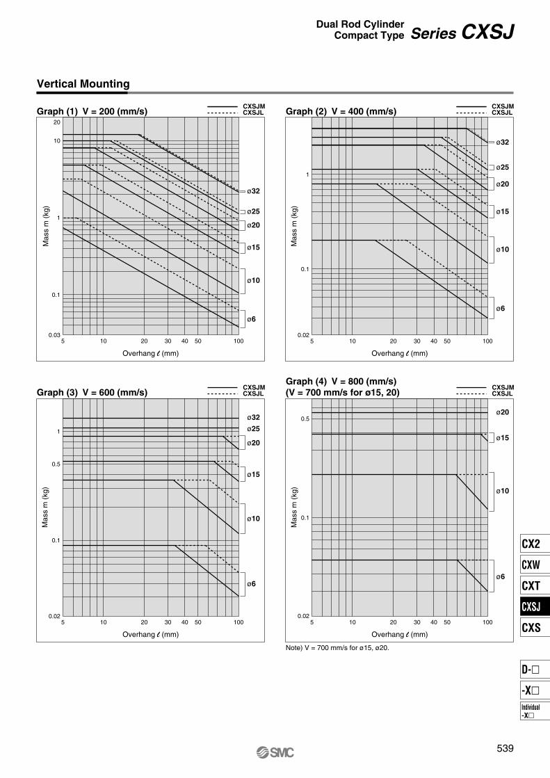
Vertical Mounting
10 20 30 40 50 100
1
10
Overhang l (mm) Overhang l (mm)
0.1
5
10 20 30 40 50 1005
ø10
ø15
ø20
ø25
ø32
10 20 30 40 50 100
1
0.1
5
10 20 30 40 50 1005
ø10
ø15
ø20
ø25
ø32
1
0.1
ø10
ø15
ø20
ø25
ø32
CXSJMCXSJL
CXSJMCXSJL
0.1
0.5
0.5
ø10
ø15
ø20
20
0.03
0.02
0.02
0.02
ø6
ø6
ø6ø6
Graph (1) V = 200 (mm/s)
CXSJMCXSJLGraph (3) V = 600 (mm/s)
CXSJMCXSJL
Graph (4) V = 800 (mm/s)
(V = 700 mm/s for ø15, 20)
Graph (2) V = 400 (mm/s)
Mas
s m
(kg
)
Mas
s m
(kg
)M
ass
m (
kg)
Mas
s m
(kg
)
Overhang l (mm) Overhang l (mm)
Note) V = 700 mm/s for ø15, ø20.
539
Series CXSJDual Rod Cylinder
Compact Type
CX2
CXW
CXT
CXSJ
CXS
Individual-X�
D-�
-X�

Mas
s m
(kg
)
Mas
s m
(kg
)
20 400.01
0.02
0.03
0.04
0.05
0.1
0.2
600
CXSJM6
CXSJL6
Graph (6) Up to 30 mm strokeGraph (5) Up to 10 mm strokeV = Up to 400 mm/sV = Up to 800 mm/s
Overhang l (mm)Overhang l (mm)
Overhang l (mm)
0.1
1
0.010
ø10
ø15
ø20
ø25
ø32
20 40 10060 80
Overhang l (mm)
0 20 40 10060 80
ø10
ø15
ø20
ø25
ø32
Graph (8) V = Up to 400 mm/s; Up to 10 mm strokeCXSJMCXSJL Graph (9) V = Over 400 mm/s; Up to 10 mm stroke
V = Up to 400 mm/sV = Up to 800 mm/s
CXSJMCXSJL
Mas
s m
(kg
)
0.1
1
0.01
Mas
s m
(kg
)
Overhang l (mm)
0.1
1
0.010 20 40 10060 80
Overhang l (mm)
0 20 40 10060 80
Mas
s m
(kg
)
0.1
1
0.01
Mas
s m
(kg
)
Graph (12) V = Up to 400 mm/s; Up to 50 mm strokeCXSJMCXSJL Graph (13) V = Over 400 mm/s; Up to 50 mm stroke
CXSJMCXSJL
ø10
ø15
ø20
ø25
ø32
ø10
ø15
ø20
ø25
ø32
20 400.01
0.02
0.03
0.04
0.05
0.1
0.2
600
CXSJM6CXSJL6
Horizontal Mounting
5540
Series CXSJ

Graph (14) V = Over 400 mm/s; Up to 75 mm strokeCXSJMCXSJL Graph (15) V = Over 400 mm/s; Up to 100 mm stroke
CXSJMCXSJL
ø10 ø15
ø20
ø25
ø32
ø15
ø20
ø25
ø32
ø10
ø15
ø20
ø25
ø32
ø10
ø15
ø20
ø25
ø32
Graph (10) V = Up to 400 mm/s; Up to 30 mm strokeCXSJMCXSJL Graph (11) V = Over 400 mm/s; Up to 30 mm stroke
CXSJMCXSJL
Graph (7) Up to 50 mm stroke
Mas
s m
(kg
)
20 400.01
0.02
0.03
0.04
0.05
0.1
0.2
600
Overhang l (mm)
CXSJM6
V = Up to 800mm/s
Overhang l (mm)
0 20 40 10060 80
0.1
1
0.01
Mas
s m
(kg
)
Overhang l (mm)
0 20 40 10060 80
0.1
1
0.01
Mas
s m
(kg
)
Overhang l (mm)
0 20 40 10060 80
0.1
1
0.01
Mas
s m
(kg
)
Overhang l (mm)
0 20 40 10060 80
0.1
1
0.01
Mas
s m
(kg
)
CXSJL6
541
Series CXSJDual Rod Cylinder
Compact Type
CX2
CXW
CXT
CXSJ
CXS
Individual-X�
D-�
-X�
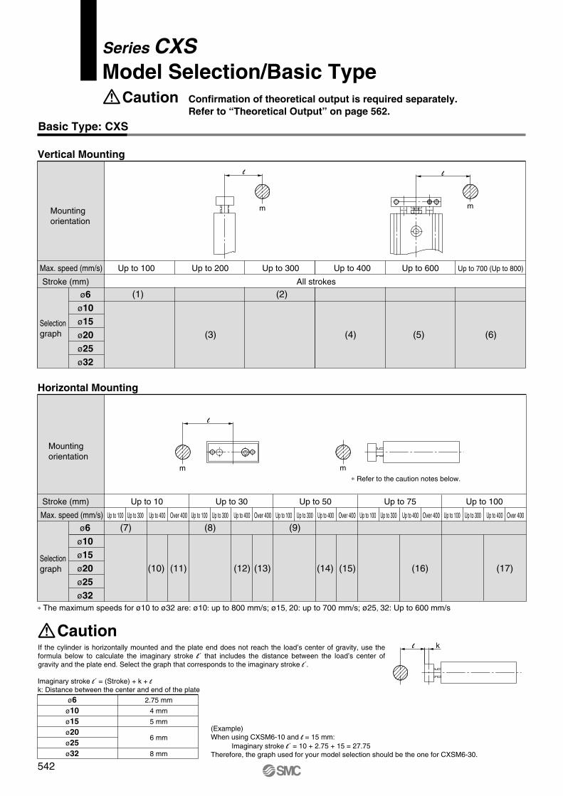
Model Selection/Basic Type
Series CXS
Basic Type: CXS
Max. speed (mm/s)
Stroke (mm)
ø6
ø10
ø15
ø20
ø25
ø32
Selectiongraph
Mountingorientation
Vertical Mounting
Up to 100
All strokes
(3)
(1) (2)
(4)
Up to 300 Up to 400
(5)
Up to 600
(6)
Up to 700 (Up to 800)Up to 200
Caution Confirmation of theoretical output is required separately.
Refer to “Theoretical Output” on page 562.
Imaginary stroke l´ = (Stroke) + k + lk: Distance between the center and end of the plate
ø6
ø10
ø15
ø20
ø25
ø32
2.75 mm
4 mm
5 mm
6 mm
8 mm
Caution
Stroke (mm)
Max. speed (mm/s)
ø6
ø10
ø15
ø20
ø25
ø32
Selectiongraph
Mountingorientation
Horizontal Mounting
Up to 10
Up to 100 Up to 300 Up to 400 Over 400
Up to 30
Up to 100 Up to 300 Up to 400 Over 400
Up to 50
Up to 100 Up to 300 Up to 400 Over 400
Up to 75
Up to 100 Up to 300 Up to 400 Over 400
Up to 100
Up to 100 Up to 300 Up to 400 Over 400
(7) (8) (9)
(10) (11) (12) (13) (14) (15) (17)(16)
k
m m
m m
∗ The maximum speeds for ø10 to ø32 are: ø10: up to 800 mm/s; ø15, 20: up to 700 mm/s; ø25, 32: Up to 600 mm/s
∗ Refer to the caution notes below.
If the cylinder is horizontally mounted and the plate end does not reach the load’s center of gravity, use the formula below to calculate the imaginary stroke l´ that includes the distance between the load’s center of gravity and the plate end. Select the graph that corresponds to the imaginary stroke l´.
(Example)When using CXSM6-10 and l = 15 mm:
Imaginary stroke l´ = 10 + 2.75 + 15 = 27.75Therefore, the graph used for your model selection should be the one for CXSM6-30.
542
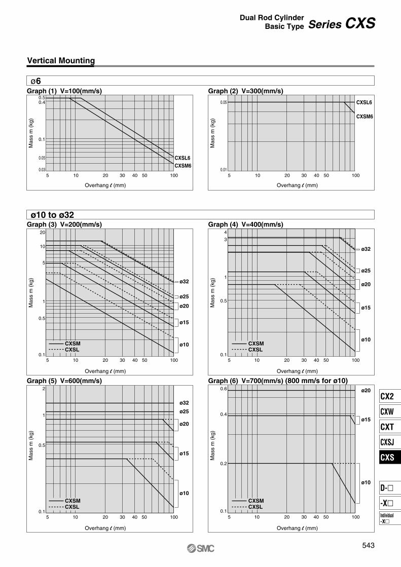
Vertical Mounting
ø6
Overhang l (mm)
50.03
0.05
0.1
0.50.4
10 20 30 40 50 100
CXSL6
CXSM6
50.1
0.5
1
5
10
20
10 20 30 40 50 100
ø32
ø25
ø20
ø15
ø10
ø32
ø25
ø20
ø15
ø10
ø10
ø15
ø20
ø10
ø15
ø20
ø25
ø32
50.01
0.05
10 20 30 40 50 100
CXSL6
CXSM6
Mas
s m
(kg
)
Mas
s m
(kg
)
Mas
s m
(kg
)
Mas
s m
(kg
)
Mas
s m
(kg
)
Mas
s m
(kg
)
Overhang l (mm)
Overhang l (mm) Overhang l (mm)
Overhang l (mm) Overhang l (mm)
50.1
0.5
1
2
10 20 30 40 50 100
50.1
0.5
1
4
3
10 20 30 40 50 100
CXSM
CXSL
CXSM
CXSL
CXSM
CXSL
CXSM
CXSL
5
0.6
0.4
0.2
0.110 20 30 40 50 100
ø10 to ø32
Graph (1) V=100(mm/s) Graph (2) V=300(mm/s)
Graph (3) V=200(mm/s) Graph (4) V=400(mm/s)
Graph (5) V=600(mm/s) Graph (6) V=700(mm/s) (800 mm/s for ø10)
543
Series CXSDual Rod Cylinder
Basic Type
CX2
CXW
CXT
CXSJ
CXS
Individual-X�
D-�
-X�

Horizontal Mounting
ø6 ø10 to ø32
Overhang l (mm)
00.01
0.05
0.1
20 40 60 80 100
Mas
s m
(kg
)
Overhang l (mm)
00.01
0.05
0.1
0.5
1
32
20 40 60 80 100M
ass
m (
kg)
ø32
ø25
ø20
ø15
ø10
Graph (7) Up to 10 st Graph (10) V = Up to 400 mm/s; Up to 10 st
V = Up to 100 mm/sV = Up to 300 mm/s
Overhang l (mm)
00.01
0.02
0.03
0.04
0.05
20 40 60 80 100
CXSL6
CXSM6
Mas
s m
(kg
)
Graph (9) Up to 50 st
V = Up to 100 mm/sV = Up to 300 mm/s
00.01
0.05
20 40 60 80 100
CXSL6
CXSM6
Mas
s m
(kg
)
Overhang l (mm)
Graph (8) Up to 30 st
V = Up to 100 mm/sV = Up to 300 mm/s
CXSM
CXSL
00.01
0.05
0.1
0.5
1
2
20 40 60 80 100
Mas
s m
(kg
)
Overhang l (mm)
ø32
ø25
ø20
ø15
ø10
Graph (11) V = Over 400 mm/s; Up to 10 st
CXSM
CXSL
Overhang l (mm)
00.01
0.05
1
2
0.1
20 40 60 80 100
Mas
s m
(kg
)
ø32
ø25
ø20
ø15
ø10
Graph (12) V = Up to 400 mm/s; Up to 30 st
CXSM
CXSL
CXSM6
CXSL6
544
Series CXS
Horizontal Mounting
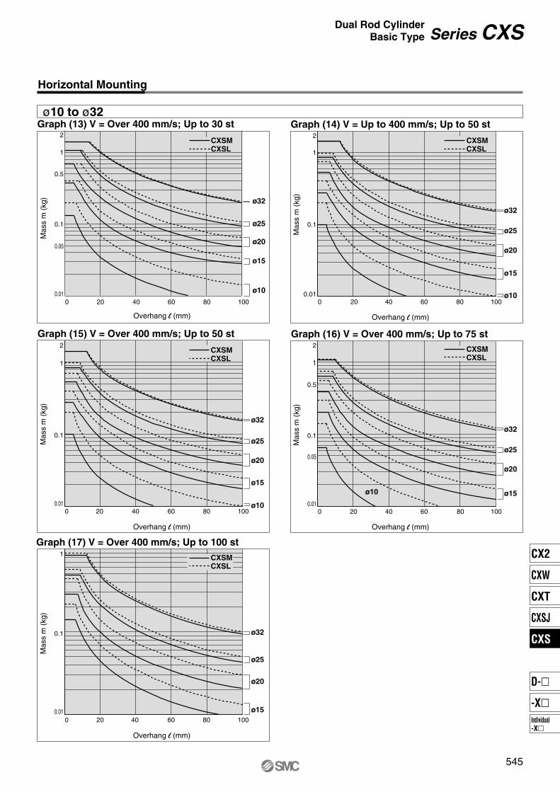
ø10 to ø32
Series CXSDual Rod Cylinder
Basic Type
ø32
ø25
ø20
ø15
ø10
ø10
ø15
ø20
ø25
ø32
Mas
s m
(kg
)
Mas
s m
(kg
)
Overhang l (mm)
Overhang l (mm)
00.01
1
0.1
2
20 40 60 80 100
0
2
0.01
0.1
1
20 40 60 80 100
ø32
ø25
ø20
ø15ø10
ø15
ø20
ø25
ø32
Mas
s m
(kg
)
Mas
s m
(kg
)
Overhang l (mm)
Overhang l (mm)
00.01
0.05
0.1
0.5
1
2
20 40 60 80 100
0
1
0.01
0.1
20 40 60 80 100
00.01
0.05
0.1
0.5
1
2
20 40 60 80 100
Mas
s m
(kg
)
Overhang l (mm)
ø32
ø25
ø20
ø15
ø10
Graph (13) V = Over 400 mm/s; Up to 30 st
CXSM
CXSL
Graph (14) V = Up to 400 mm/s; Up to 50 st
Graph (15) V = Over 400 mm/s; Up to 50 st
CXSM
CXSL
CXSM
CXSL
Graph (16) V = Over 400 mm/s; Up to 75 st
Graph (17) V = Over 400 mm/s; Up to 100 st
CXSM
CXSL
CXSM
CXSL
545
CX2
CXW
CXT
CXSJ
CXS
Individual-X�
D-�
-X�
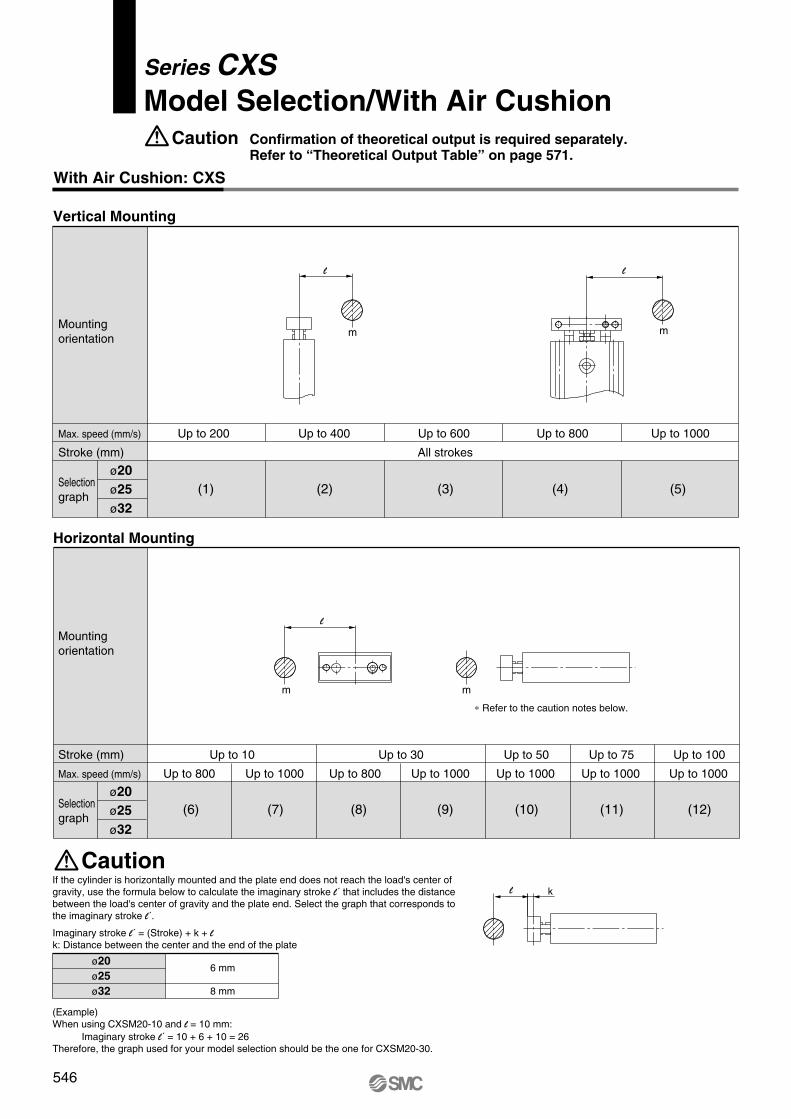
Model Selection/With Air Cushion
Series CXS
With Air Cushion: CXS
Caution Confirmation of theoretical output is required separately.
Refer to “Theoretical Output Table” on page 571.
Max. speed (mm/s)
Stroke (mm)
ø25
ø20
ø32
Selectiongraph
Mountingorientation
Vertical Mounting
Up to 200
All strokes
(1) (2) (3) (4)
Up to 600 Up to 800
(5)
Up to 1000Up to 400
Imaginary stroke l´ = (Stroke) + k + lk: Distance between the center and the end of the plate
ø20
ø25
ø32
6 mm
8 mm
Stroke (mm)
Max. speed (mm/s)
ø25
ø20
ø32
Selectiongraph
Mountingorientation
Horizontal Mounting
Up to 10 Up to 30
Up to 1000Up to 800 Up to 1000 Up to 1000Up to 800
Up to 50
(6) (7) (8) (9) (10)
Up to 1000
Up to 75
(11)
Up to 1000
Up to 100
(12)
l
m
l
m
m m
l
l k
∗ Refer to the caution notes below.
If the cylinder is horizontally mounted and the plate end does not reach the load's center of gravity, use the formula below to calculate the imaginary stroke l´ that includes the distance between the load's center of gravity and the plate end. Select the graph that corresponds to the imaginary stroke l´.
(Example)When using CXSM20-10 and l = 10 mm:
Imaginary stroke l´ = 10 + 6 + 10 = 26Therefore, the graph used for your model selection should be the one for CXSM20-30.
Caution
546

Vertical Mounting
ø32
ø25
ø20ø20
ø25
ø32
Mas
s m
(kg
)
Mas
s m
(kg
)
Overhang l (mm) Overhang l (mm)
50.6
1
65
10 20 30 40 50 100 5
1
2
3
0.610 20 30 40 50 100
ø32
ø25
ø20
Mas
s m
(kg
)
Overhang l (mm)
5
1
0.6
3
2
10 20 30 40 50 100
Overhang l (mm)
5
10
50
1
0.610 20 30 40 50 100 5
1
0.6
10
20
10 20 30 40 50 100
Mas
s m
(kg
)
Mas
s m
(kg
)Overhang l (mm)
ø32
ø25
ø20
ø32
ø25
ø20
Graph (1) V = 200 mm/s
CXSM
CXSL
Graph (5) V = 1000 mm/s
CXSM
CXSL
Graph (2) V = 400 mm/s
CXSM
CXSL
Graph (3) V = 600 mm/s
CXSM
CXSL
Graph (4) V = 800 mm/s
CXSM
CXSL
547
Series CXSDual Rod Cylinder
With Air Cushion
CX2
CXW
CXT
CXSJ
CXS
Individual-X�
D-�
-X�
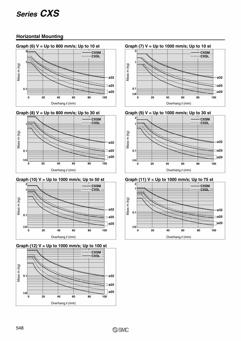
Horizontal Mounting
Overhang l (mm)
0
0.1
3
1
20 40 60 80 100
0
0.04
0.1
1
20 40 60 80 100
0
0.03
0.1
1
2
20 40 60 80 100
0
0.06
0.1
1
3
20 40 60 80 100
0
0.04
0.1
2
1
20 40 60 80 100
Mas
s m
(kg
)
Mas
s m
(kg
)
Mas
s m
(kg
)
Mas
s m
(kg
)
Mas
s m
(kg
)
Mas
s m
(kg
)
Mas
s m
(kg
)
Overhang l (mm)
Overhang l (mm) Overhang l (mm)
Overhang l (mm) Overhang l (mm)
Overhang l (mm)
0
0.02
0.1
20 40 60 80 100
0
0.02
0.1
1
2
20 40 60 80 100
ø32
ø25
ø20
ø32
ø25
ø20
ø32
ø25
ø20
ø32
ø25
ø20
ø32
ø25
ø20
ø32
ø25
ø20
ø32
ø25
ø20
Graph (6) V = Up to 800 mm/s; Up to 10 st
CXSM
CXSL
Graph (7) V = Up to 1000 mm/s; Up to 10 st
CXSM
CXSL
Graph (8) V = Up to 800 mm/s; Up to 30 st
CXSM
CXSL
Graph (9) V = Up to 1000 mm/s; Up to 30 st
CXSM
CXSL
Graph (10) V = Up to 1000 mm/s; Up to 50 st
CXSM
CXSL
Graph (12) V = Up to 1000 mm/s; Up to 100 st
CXSM
CXSL
Graph (11) V = Up to 1000 mm/s; Up to 75 st
CXSM
CXSL
548
Series CXS

Dual Rod Cylinder/Compact Type
ø6, ø10, ø15, ø20, ø25, ø32
Series CXSJ
How to Order
50 M9BWCXSJ
Compact type
SM P6
Applicable Auto Switches/Refer to pages 1719 to 1827 for detailed auto switch specifications.
∗ Solid state auto switches marked with “�” are produced upon receipt of order.
24 V
Special functionTypeElectrical
entryIndicator
light
Wiring(output)
Load voltage
ACDC
Auto switch modelLead wire length (m)∗
0.5(Nil)
3(L)
5(Z)
���
���
1(M)
—
—
—
IC circuit
—
IC circuit
Applicable load
Perpendicular In-line
IC circuit
—
IC circuit
—
IC circuit
—
Diagnostic indication(2-color display)
Water resistant(2-color display)
Yes
None
Yes
Grommet
Grommet
3-wire (NPN equiv.)
Pre-wiredconnector
—
—
—Relay,PLC
—
Relay,PLC
—
— 5 V
12 V
5 V, 12 V
5 V, 12 V
12 V
5 V, 12 V
12 V
5 V, 12 V
12 V
24 V
A96V
A93V
A90V
A96
A93
A90
—
100 V
100 V or less
—
—
2-wire
3-wire (NPN)
3-wire (PNP)
2-wire
3-wire (NPN)
3-wire (PNP)
2-wire
3-wire (NPN)
3-wire (PNP)
2-wire
—
—
—
���������
���������
���������
���������
M9NV
M9PV
M9BV
M9NWV
M9PWV
M9BWV
M9NAV
M9PAV
M9BAV
M9N
M9P
M9B
M9NW
M9PW
M9BW
M9NA
M9PA
M9BA
���������
Nil
TN
TF
Port thread type
M thread
Rc 1/8
NPT 1/8
G 1/8
ø6 to ø25
ø32
M
L
Bearing type
Slide bearing
Ball bushing bearing
Nil
P
Piping
Standard (ø6 to ø32)
Axial (ø6, ø10) Port location
Standard piping Axial piping
Port location
Made to Order(Refer to the below.)Nil
S
n
Number of auto switches
2 pcs.
1 pc.
“n” pcs.
Nil
Auto switch
Without auto switch (with built-in magnet)
∗ Refer to the below table for auto switch model numbers.
Bore size
6
10
15
20
25
32
Bore size / Stroke
Standard stroke
10, 20, 30, 40, 50
10, 20, 30, 40, 50, 75
10, 20, 30, 40, 50, 75, 100
(mm)
XB6
XB13
XC6 Note)
XC19
XC22
Heat resistant cylinder (–10 to 150°C)
Low speed cylinder (5 to 50 mm/s)
Made of stainless steel
Intermediate stroke (spacer)
Fluoro rubber seals
Symbol Specifications
Made to Order (For details, refer to pages 1851 to 1954.)
Note) Slide bearing type (M) only
So
lid
sta
te s
wit
ch
Reed
sw
itch
∗ Lead wire length symbols: 0.5 m ·················· Nil (Example) M9NW 1 m ·················· M M9NWM 3 m ·················· L M9NWL 5 m ·················· Z M9NWZ
• Since there are applicable auto switches other than listed, refer to page 559 for details.• For details about switch with pre-wired connector, refer to pages 1784 and 1785.∗ Auto switches are shipped together (not assembled).
549
CX2
CXW
CXT
CXSJ
CXS
Individual-X�
D-�
-X�

0
0.5
1
1.5
2
2.5
3
10 20 30 40 50 60 70 80 90 100
Maxim
um
lo
ad
mass W
(kg
)
Cylinder stroke (mm)
CXSJM
CXSJL
ø6
ø32
ø25
ø20
ø15
ø10
Mass
Model
CXSJM6
CXSJL6
CXSJM10
CXSJL10
CXSJM15
CXSJL15
CXSJM20
CXSJL20
CXSJM25
CXSJL25
CXSJM32
CXSJL32
Standard stroke (mm)
10
0.047
0.048
0.099
0.106
0.198
0.218
0.345
0.375
0.506
0.516
1.022
1.032
20
0.057
0.058
0.114
0.121
0.219
0.239
0.371
0.401
0.544
0.554
1.078
1.088
30
0.067
0.068
0.129
0.136
0.240
0.260
0.397
0.427
0.582
0.592
1.134
1.144
40
0.077
0.078
0.144
0.151
0.261
0.281
0.423
0.453
0.620
0.630
1.190
1.200
50
0.087
0.088
0.159
0.166
0.282
0.302
0.449
0.479
0.658
0.668
1.246
1.256
100
—
—
—
—
0.387
0.407
0.579
0.609
0.848
0.858
1.526
1.536
75
—
—
0.198
0.205
0.335
0.355
0.514
0.544
0.753
0.763
1.386
1.396
(kg)
Specifications
Fluid
Proof pressure
Maximum operating pressure
Minimum operating pressure
Ambient and fluid temperature
Piston speed
Cushion
Stroke adjustable range
Port size
Allowable kinetic energy
Bore size (mm)
Air (Non-lube)
1.05 MPa
0.7 MPa
–10 to 60°C (No freezing)
30 to 700 mm/s
M5 x 0.8
0.05 MPa
0 to –5 mm compared to the standard stroke
Standard Stroke
CXSJ�6
CXSJ�10
CXSJ�15
CXSJ�20, 25, 32
Model Standard stroke
10, 20, 30, 40, 50
10, 20, 30, 40, 50, 75
10, 20, 30, 40, 50, 75, 100
Manufacturable stroke range
60 to 100
80 to 150
110 to 150
110 to 200
(mm)
∗ Strokes beyond the standard stroke range are available as a special order.
6
0.15 MPa
M3 x 0.5
10 15 20 25 32
Rc (NPT, PF) 1/8
0.1 MPa
30 to 800 mm/s 30 to 600 mm/s
Rubber bumper on both ends
Theoretical Output
0.1
—
—
15.7
10.0
35.3
25.2
62.8
47.1
98.2
75.6
161
121
0.2
11.2
6.2
31.4
20.0
70.6
50.4
126
94.2
196
151
322
241
0.3
16.8
9.3
47.1
30.0
106
75.6
188
141
295
227
482
362
0.4
22.4
12.4
62.8
40.0
141
101
251
188
393
302
643
482
0.5
28.0
15.5
78.5
50.0
177
126
314
236
491
378
804
603
0.6
33.6
18.6
94.2
60.0
212
151
377
283
589
454
965
724
0.7
39.2
21.7
110
70.0
247
176
440
330
687
529
1126
844
0.15
8.4
4.6
—
—
—
—
—
—
—
—
—
—
Operating pressure (MPa)(N)
Operatingdirection
Piston area(mm2)
56
31
157
100
353
252
628
471
982
756
1608
1206
OUT
IN
OUT
IN
OUT
IN
OUT
IN
OUT
IN
OUT
IN
Rod size(mm)
Bore size(mm)
4
6
8
10
12
16
Note) Theoretical output (N) = Pressure (MPa) x Piston area (mm2)
CXSJ�6
CXSJ�10
CXSJ�15
CXSJ�20
CXSJ�25
CXSJ�32
Note) For axial piping of CXSJ�6P-� and CXSJ�10P-�, please add the following mass. CXSJ�6P-�: 0.009 kg, CXSJ�10P-�: 0.014 kg
0.016 J 0.064 J 0.095 J 0.17 J 0.27 J 0.32 J
Maximum Load Mass
When the cylinder is mounted as shown in the diagrams below, the maximum load mass W should not exceed the values illustrated in the graph immediately
Operating Conditions
Non-rotating Accuracy
CXSJ�6 to 32Deflection at the Plate End
Non-rotating accuracy θ° without a load should be less than or equal to the value provided in the table below as a guide.
An approximate plate-end deflection X without a load is shown in the graph below.
Bore size (mm)
CXSJM (Slide bearing)CXSJL (Ball bushing bearing)
ø6 to ø32
±0.1°
Housing
Plate
Extended rod
Defle
ctio
nX
mm
Def
lect
ion
X (
mm
)
Stroke (mm)
550
Series CXSJ
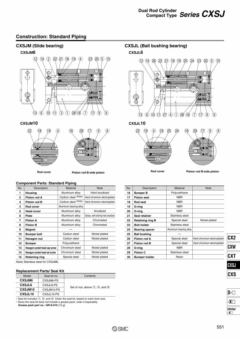
CXSJM (Slide bearing) CXSJL (Ball bushing bearing)
Piston rod B-side pistonRod cover
CXSJL6
CXSJL10
CXSJM6
CXSJM10
Piston rod B-side pistonRod cover
!5t@0@3r!9!8@1@2w!4!2
!3 y !0 !1 e q @8!6 u !7 o i
!5t@0@3@4@5!9!8@1@2@6!4!2
!3 y !0 !1 @7 rq @8 !6 u !7 o i
r!9!8@2 !6 @9 !7 o i @4@5!8r!9@2 !6 @9 !7 o i
Construction: Standard Piping
∗ Seal kit includes !7, !8, and @0. Order the seal kit, based on each bore size.∗ Since the seal kit does not include a grease pack, order it separately. Grease pack part no.: GR-S-010 (10 g)
Replacement Parts/ Seal Kit
Component Parts: Standard Piping
No. Description
Housing
Piston rod A
Piston rod B
Rod cover
Head cover
Plate
Piston A
Piston B
Magnet
Bumper bolt
Hexagon nut
Bumper
Hexagon socket head cap screw
Hexagon socket head set screw
Retaining ring
Material
Aluminum alloy
Carbon steel
Carbon steel
Aluminum bearing alloy
Aluminum alloy
Aluminum alloy
Aluminum alloy
Aluminum alloy
—
Carbon steel
Carbon steel
Polyurethane
Chromium steel
Chromium steel
Special steel
Note
Hard anodized
Hard chromium electroplated
Hard chromium electroplated
Anodized
Glossy, self-coloring hard anodized
Chromated
Chromated
Nickel plated
Nickel plated
Nickel plated
Nickel plated
Nickel plated
1
2
3
4
5
6
7
8
9
10
11
12
13
14
15
No. Description
Bumper B
Piston seal
Rod seal
O-ring
O-ring
Seal retainer
Retaining ring B
Bolt holder
Bearing spacer
Ball bushing
Piston rod A
Piston rod B
O-ring
Piston C
Bumper holder
Material
Polyurethane
NBR
NBR
NBR
NBR
Stainless steel
Special steel
Stainless steel
Aluminum bearing alloy
—
Special steel
Special steel
NBR
Stainless steel
Resin
Note
Nickel plated
Hard chromium electroplated
Hard chromium electroplated
16
17
18
19
20
21
22
23
24
25
26
27
28
29
30
Seal kit no.
CXSJM6-PS
CXSJL6-PS
CXSJM10-PS
CXSJL10-PS
Model Contents
Set of nos. above !7, !8, and @0
CXSJM6
CXSJL6
CXSJM10
CXSJL10
Note) Stainless steel for CXSJM6.
Note)
Note)
551
Series CXSJDual Rod Cylinder
Compact Type
CX2
CXW
CXT
CXSJ
CXS
Individual-X�
D-�
-X�
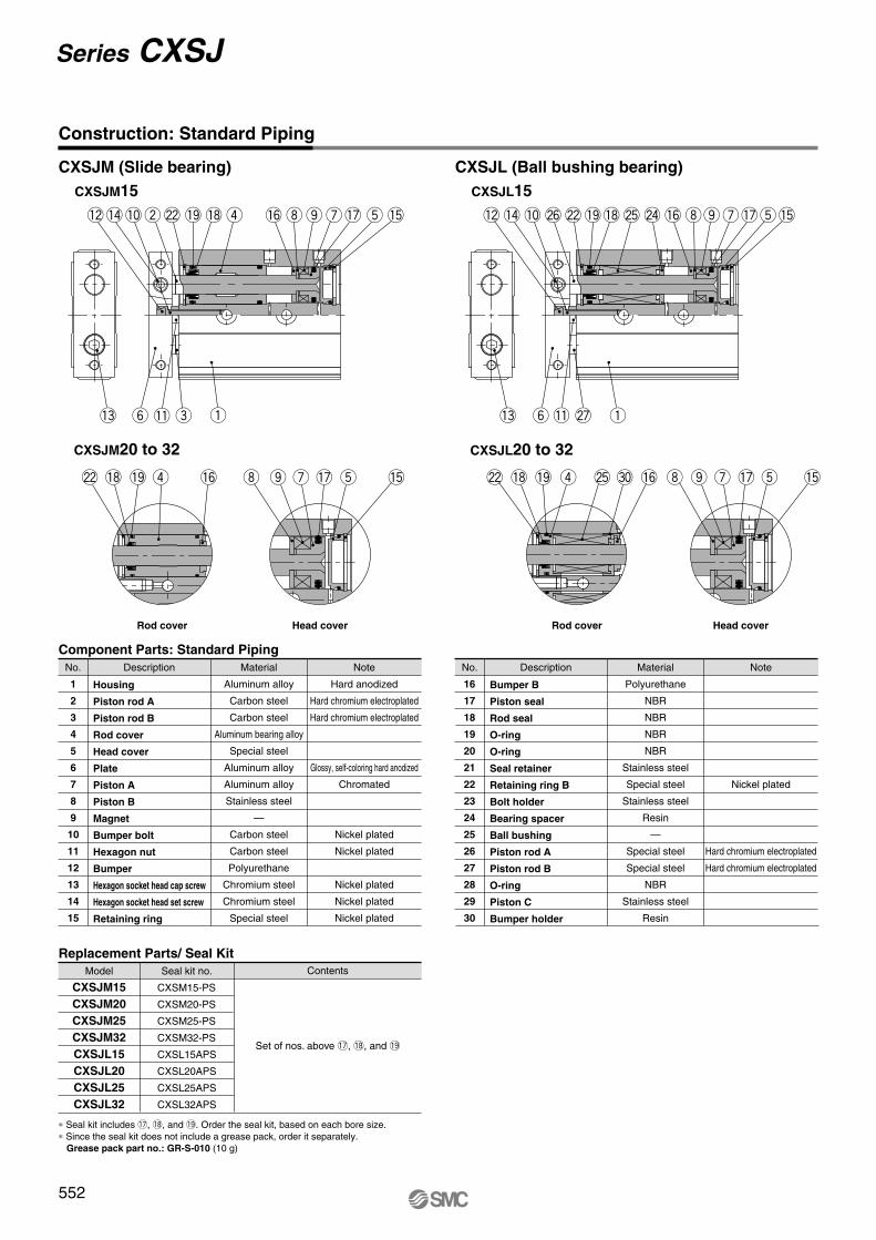
CXSJM (Slide bearing) CXSJL (Ball bushing bearing)
CXSJL15
CXSJL20 to 32
CXSJM15
CXSJM20 to 32
!5tr!9 !8@2w!4!2 !0 !6 i u!7o
!3 y !1 e q
r!9!8@2 !6 oi u !7 !5t !6 i u !7o !5t@5r!9!8@2 #0
!0 !6 i u!7o
!3 y !1 q
!5t@4@5!9!8@2@6!4!2
@7
Construction: Standard Piping
Rod cover Head cover Rod cover Head cover
Component Parts: Standard Piping
No. Description
Housing
Piston rod A
Piston rod B
Rod cover
Head cover
Plate
Piston A
Piston B
Magnet
Bumper bolt
Hexagon nut
Bumper
Hexagon socket head cap screw
Hexagon socket head set screw
Retaining ring
Material
Aluminum alloy
Carbon steel
Carbon steel
Aluminum bearing alloy
Special steel
Aluminum alloy
Aluminum alloy
Stainless steel
—
Carbon steel
Carbon steel
Polyurethane
Chromium steel
Chromium steel
Special steel
Note
Hard anodized
Hard chromium electroplated
Hard chromium electroplated
Glossy, self-coloring hard anodized
Chromated
Nickel plated
Nickel plated
Nickel plated
Nickel plated
Nickel plated
No. Description
Bumper B
Piston seal
Rod seal
O-ring
O-ring
Seal retainer
Retaining ring B
Bolt holder
Bearing spacer
Ball bushing
Piston rod A
Piston rod B
O-ring
Piston C
Bumper holder
Material
Polyurethane
NBR
NBR
NBR
NBR
Stainless steel
Special steel
Stainless steel
Resin
—
Special steel
Special steel
NBR
Stainless steel
Resin
Note
Nickel plated
Hard chromium electroplated
Hard chromium electroplated
Replacement Parts/ Seal Kit
Seal kit no.
CXSM15-PS
CXSM20-PS
CXSM25-PS
CXSM32-PS
CXSL15APS
CXSL20APS
CXSL25APS
CXSL32APS
Model Contents
Set of nos. above !7, !8, and !9
CXSJM15
CXSJM20
CXSJM25
CXSJM32
CXSJL15
CXSJL20
CXSJL25
CXSJL32
1
2
3
4
5
6
7
8
9
10
11
12
13
14
15
16
17
18
19
20
21
22
23
24
25
26
27
28
29
30
∗ Seal kit includes !7, !8, and !9. Order the seal kit, based on each bore size.∗ Since the seal kit does not include a grease pack, order it separately. Grease pack part no.: GR-S-010 (10 g)
552
Series CXSJ
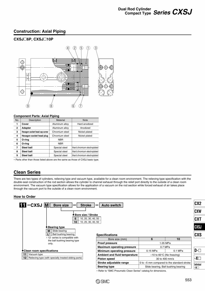
CXSJ�6P, CXSJ�10P
Bore size
How to Order
CXSJ M Stroke Auto switch
Clean Series
There are two types of cylinders, relieving type and vacuum type, available for a clean room environment. The relieving type specification with the double-seal construction of the rod section allows the cylinder to channel exhaust through the relief port directly to the outside of a clean room environment. The vacuum type specification allows for the application of a vacuum on the rod section while forced exhaust of air takes place through the vacuum port to the outside of a clean room environment.
11
eqtwr
uyio
Construction: Axial Piping
Component Parts: Axial Piping
No. Description
Cover
Adapter
Hexagon socket head cap screw
Hexagon socket head plug
O-ring
O-ring
Steel ball
Steel ball
Steel ball
Material
Aluminum alloy
Aluminum alloy
Chromium steel
Chromium steel
NBR
NBR
Special steel
Special steel
Special steel
Note
Hard anodized
Anodized
Nickel plated
Nickel plated
Hard chromium electroplated
Hard chromium electroplated
Hard chromium electroplated
1
2
3
4
5
6
7
8
9
∗ Parts other than those listed above are the same as those of CXSJ basic type.
Bore size / Stroke
6
10
10, 20, 30, 40, 5010, 20, 30, 40, 50
Bearing type
M
L∗Slide bearingBall bushing bearing
∗ 12- series is compatible with the ball bushing bearing type only.
Clean room specifications
11
12
Vacuum typeRelieving type (with specially treated sliding parts)
∗ Refer to “SMC Pneumatic Clean Series” catalog for dimensions.
Specifications
Proof pressure
Maximum operating pressure
Minimum operating pressure
Ambient and fluid temperature
Piston speed
Stroke adjustable range
Bearing type
Bore size (mm)1.05 MPa
0.7 MPa
–10 to 60°C (No freezing)
30 to 400 mm/s
0 to –5 mm compared to the standard stroke
Slide bearing, Ball bushing bearing
6
0.15 MPa 0.1 MPa
10
553
Series CXSJDual Rod Cylinder
Compact Type
CX2
CXW
CXT
CXSJ
CXS
Individual-X�
D-�
-X�

11
3132
5.5
0.5
13.4
1.2
5.3
5.3
Dimensions: ø6 Standard Piping
4 x M3 x 0.5 thread depth 3.5
2 x M3 x 0.5 thread depth 3
(Piping port)
10 9 + Stroke
5.5
6.7
2.7
8
20.5
20
2 x M3 x 0.5 throughø3.4 throughø6.5 counterbore with depth 5 (Opposite side: Same)
Bolt holder∗2.75
5.5 4.5
12
Stroke
1625
±0.2
42 + Stroke
5 + Stroke
32 + Stroke
2 x M3 x 0.5 through
25±0
.2
2 x M3 x 0.5 through
ø4
2.75 (12) (5 + Stroke)
25±0
.2
∗ For bolt holder, refer to page 560, “Mounting”.
554
Series CXSJ
15
131
14042
8 3.5
20
4 16
16
88
7.5
3.5
86.5
28.5 8
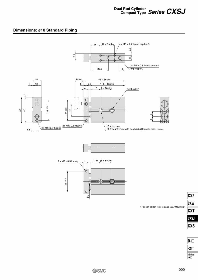
Dimensions: ø10 Standard Piping
12 + Stroke 4 x M3 x 0.5 thread depth 4.5
2 x M5 x 0.8 thread depth 4(Piping port)
Stroke
8 + Stroke
33±0
.2
56 + Stroke
44.5 + Stroke
2 x M3 x 0.5 through
Bolt holder∗
ø3.4 throughø6.5 counterbore with depth 5.5 (Opposite side: Same)
33±0
.2
2 x M4 x 0.7 through
4
33±0
.2
(16) (8 + Stroke)2 x M3 x 0.5 through
ø6
∗ For bolt holder, refer to page 560, “Mounting”.
555
Series CXSJDual Rod Cylinder
Compact Type
CX2
CXW
CXT
CXSJ
CXS
Individual-X�
D-�
-X�

CXSJ�6P
CXSJ�10P
Dimensions: ø6, ø10 Axial Piping
5 + Stroke12
ST
6.7
7
0.3
0.3
1631.4
(49 + Stroke)
9 + Stroke10
32 + Stroke
42 + Stroke
12.8
4 x M1.6 x 0.35 x 6 l
2 x M3 x 0.5 thread depth 3(Piping port) OUT
Steel balls
IN
8.5
7.5
ST
8 + Stroke16
56 + Stroke
44.5 + Stroke
0.3
14.4
0.3
41.4
20
(64.5 + Stroke)
Steel balls
4 x M1.6 x 0.35 x 8 l
2 x M5 x 0.8 thread depth 4(Piping port) OUT
IN
12 + Stroke16
556
Series CXSJ
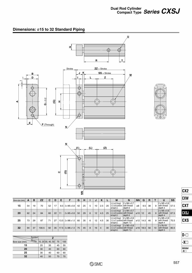
A
54
62
73
94
B
19
24
29
37
C
52
60
71
92
D
17
22
27
35
E
8.5
11
13.5
17.5
G
42
50
60
75
H
25
29
35
45
I
5
6
6
8
J
10
12
12
16
K
2.5
4.5
4.5
4
L
20
25
30
30
NN
ø8
ø10
ø12
ø16
Q
9.5
12
14.5
18.5
R
38
45
46
56
T
9
9
9
10
MF
2 x M5 x 0.8
2 x M5 x 0.8
2 x M6 x 1.0
2 x M6 x 1.0
ZZ
70
84
87
100.5
15
20
25
32
15
20
25
32
Bore size (mm)2 x 2 x ø4.3 through2 x 2 x ø8 counterbore with depth 4.32 x 2 x ø5.5 through2 x 2 x ø9.5 counterbore with depth 5.32 x 2 x ø6.5 through2 x 2 x ø11 counterbore with depth 6.32 x 2 x ø6.5 through2 x 2 x ø11 counterbore with depth 6.3
N
2 x M4 x 0.7with threaddepth 62 x M4 x 0.7with threaddepth 62 x M5 x 0.8with threaddepth 7.52 x M5 x 0.8with threaddepth 7.5
U
2 x M5 x 0.8with threaddepth 42 x M5 x 0.8with threaddepth 42 x M5 x 0.8with threaddepth 42 x Rc1/8with threaddepth 5
10, 20
25
30
30
40
30, 40, 50
35
40
40
50
75
45
60
60
70
100
55
60
60
70
ZSymbolStrokeBore size (mm)
SS
57.5
67.5
70.5
80.5
Dimensions: ø15 to 32 Standard Piping
Stroke
R TH(G
)
(G)
C
NN
(I )
A
G ±
0.2
M
F (Through)
N
I
J K SS + Stroke
L Z
ZZ + Stroke
1
1 D
B
E
Q
(L) (Z)
U
N
557
Series CXSJDual Rod Cylinder
Compact Type
CX2
CXW
CXT
CXSJ
CXS
Individual-X�
D-�
-X�
C
D
A
B
D-A9�(Reed switch) D-M9�W
D-M9�D-M9�AL
(Solid state switch)
D-M9�VD-M9�WVD-M9�AVL
(Solid state switch)
D1
D2
C2
C1
C3
B1
A1
A
B
C
D
D-A9� (Reed switch)D-M9� (Solid state switch)D-M9�WD-M9�AL
D-A9�V (Reed switch)D-M9�V (Solid state switch)D-M9�WVD-M9�AVL
A1
C1
C3
C2
Electrical entry direction:
Inward
Electrical entry direction:
Outward
D-A9�V(Reed switch)
CXSJ�6, 10
CXSJ�6,10
CXSJ�15 to 32
CXSJ�15 to 32
Auto switch mounting dimensions
Symbol
A1
A1
C1
C2
C3
15 20 25
1 2 5.54.51
1 2 5.54.5—
1 2 5.54.5—
1 2 5.54.5—
32
D-M9�, D-M9�W
D-M9�AL
D-A9�V
D-M9�WV
D-M9�AVL
Auto switch model
(mm)
(mm)
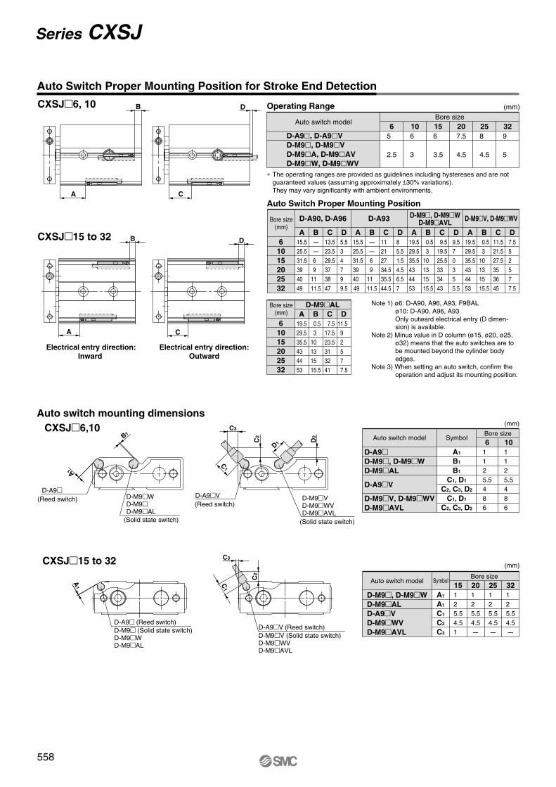
D-A9�, D-A9�V
D-M9�, D-M9�V
D-M9�A, D-M9�AV
D-M9�W, D-M9�WV
Auto switch modelBore size
Operating Range
Auto Switch Proper Mounting Position
6
5
2.5
10
6
3
15
6
3.5
20
7.5
4.5
25
8
4.5
32
9
5
A
15.525.531.539 40 49
B
——6 9
11 11.5
C
13.523.529.537 38 47
D
5.53 4 7 9 9.5
A
15.525.531.539 40 49
B
——6 9
11 11.5
C
11 21 27 34.535.544.5
D
8 5.51.54.56.57
A
19.529.535.543 44 53
B
0.53
10 13 15 15.5
C
9.519.525.533 34 43
D
9.57 0 3 5 5.5
6
10
15
20
25
32
Bore size(mm)
D-M9�, D-M9�WD-M9�AVL
D-A93D-A90, D-A96
A
19.529.535.543 44 53
B
0.53
10 13 15 15.5
C
7.517.523.531 32 41
D
11.5 9 2 5 7 7.5
6
10
15
20
25
32
Bore size(mm)
D-M9�AL
A
19.529.535.543 44 53
B
0.53
10 13 15 15.5
C
11.521.527.535 36 45
D
7.55 2 5 7 7.5
D-M9�V, D-M9�WV
Bore size
∗ The operating ranges are provided as guidelines including hystereses and are not guaranteed values (assuming approximately ±30% variations).They may vary significantly with ambient environments.
Symbol
A1
B1
B1
C1, D1
C2, C3, D2
C1, D1
C2, C3, D2
6
1 1 2 5.54 8 6
1 1 2 5.54 8 6
10
Bore size
D-A9�D-M9�,
D-M9�W
D-M9�AL
D-A9�V
D-M9�V, D-M9�WV
D-M9�AVL
Auto switch model
(mm)
Auto Switch Proper Mounting Position for Stroke End Detection
Note 1) ø6: D-A90, A96, A93, F9BALø10: D-A90, A96, A93Only outward electrical entry (D dimen-sion) is available.
Note 2) Minus value in D column (ø15, ø20, ø25, ø32) means that the auto switches are to be mounted beyond the cylinder body edges.
Note 3) When setting an auto switch, confirm the operation and adjust its mounting position.
558
Series CXSJ
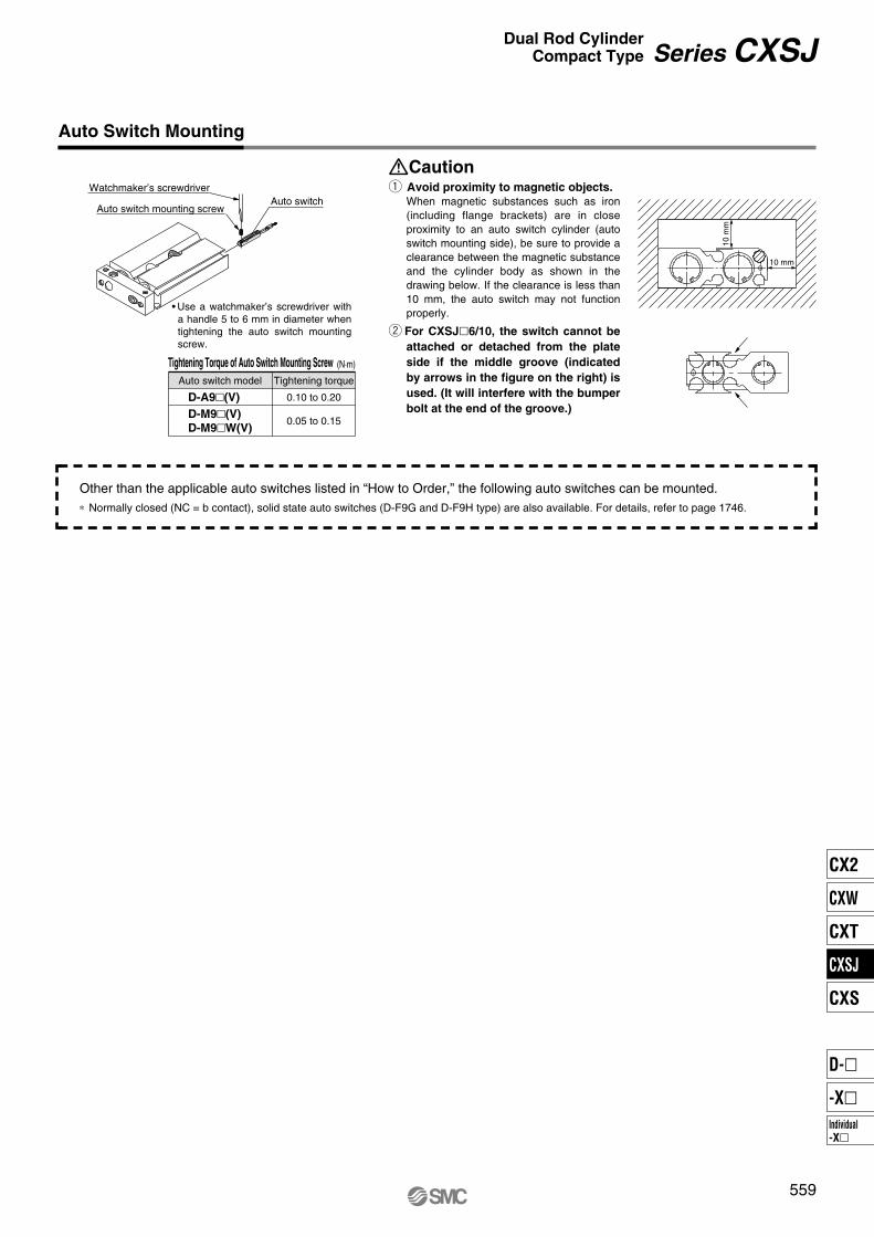
Watchmaker’s screwdriver
Auto switch mounting screwAuto switch
• Use a watchmaker’s screwdriver with a handle 5 to 6 mm in diameter when tightening the auto switch mounting screw.
Auto Switch Mounting
10 mm
10 m
m
D-A9�(V)
D-M9�(V)
D-M9�W(V)
Auto switch model
Tightening Torque of Auto Switch Mounting Screw (N·m)
Tightening torque
0.10 to 0.20
0.05 to 0.15
q Avoid proximity to magnetic objects.
When magnetic substances such as iron (including flange brackets) are in close proximity to an auto switch cylinder (auto switch mounting side), be sure to provide a clearance between the magnetic substance and the cylinder body as shown in the drawing below. If the clearance is less than 10 mm, the auto switch may not function properly.
w For CXSJ�6/10, the switch cannot be
attached or detached from the plate
side if the middle groove (indicated
by arrows in the figure on the right) is
used. (It will interfere with the bumper
bolt at the end of the groove.)
Caution
Other than the applicable auto switches listed in “How to Order,” the following auto switches can be mounted.∗ Normally closed (NC = b contact), solid state auto switches (D-F9G and D-F9H type) are also available. For details, refer to page 1746.
559
Series CXSJDual Rod Cylinder
Compact Type
CX2
CXW
CXT
CXSJ
CXS
Individual-X�
D-�
-X�
A
ASection A–A
Bolt holder (movable)
B
BSection B–B
Approx. 0.5 or less
l2 l1
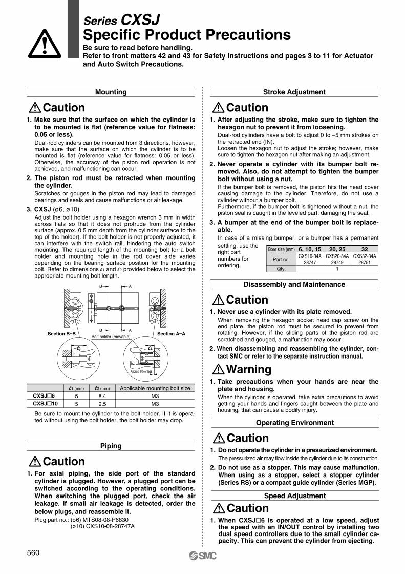
Bore size (mm)
Part no.
Qty.
6, 10, 15
CXS10-34A28747
20, 25
CXS20-34A28749
1
32
CXS32-34A28751
Series CXSJ Specific Product PrecautionsBe sure to read before handling.
Refer to front matters 42 and 43 for Safety Instructions and pages 3 to 11 for Actuator
and Auto Switch Precautions.
1. Make sure that the surface on which the cylinder is
to be mounted is flat (reference value for flatness:
0.05 or less).
Dual-rod cylinders can be mounted from 3 directions, however, make sure that the surface on which the cylinder is to be mounted is flat (reference value for flatness: 0.05 or less). Otherwise, the accuracy of the piston rod operation is not achieved, and malfunctioning can occur.
2. The piston rod must be retracted when mounting
the cylinder.
Scratches or gouges in the piston rod may lead to damaged bearings and seals and cause malfunctions or air leakage.
3. CXSJ (ø6, ø10) Adjust the bolt holder using a hexagon wrench 3 mm in width across flats so that it does not protrude from the cylinder surface (approx. 0.5 mm depth from the cylinder surface to the top of the holder). If the bolt holder is not properly adjusted, it can interfere with the switch rail, hindering the auto switch mounting. The required length of the mounting bolt for a bolt holder and mounting hole in the rod cover side varies depending on the bearing surface position for the mounting bolt. Refer to dimensions l1 and l2 provided below to select the appropriate mounting bolt length.
Mounting
Caution
Be sure to mount the cylinder to the bolt holder. If it is opera-ted without using the bolt holder, the bolt holder may drop.
CXSJ�6
CXSJ�10
l1 (mm)
55
l2 (mm)
8.49.5
Applicable mounting bolt sizeM3M3
1. For axial piping, the side port of the standard
cylinder is plugged. However, a plugged port can be
switched according to the operating conditions.
When switching the plugged port, check the air
leakage. If small air leakage is detected, order the
below plugs, and reassemble it.
Plug part no.: (ø6) MTS08-08-P6830(ø10) CXS10-08-28747A
Piping
Caution
1. After adjusting the stroke, make sure to tighten the
hexagon nut to prevent it from loosening.
Dual-rod cylinders have a bolt to adjust 0 to –5 mm strokes on the retracted end (IN).Loosen the hexagon nut to adjust the stroke; however, make sure to tighten the hexagon nut after making an adjustment.
2. Never operate a cylinder with its bumper bolt re-
moved. Also, do not attempt to tighten the bumper
bolt without using a nut.
If the bumper bolt is removed, the piston hits the head cover causing damage to the cylinder. Therefore, do not use a cylinder without a bumper bolt.Furthermore, if the bumper bolt is tightened without a nut, the piston seal is caught in the leveled part, damaging the seal.
3. A bumper at the end of the bumper bolt is replace-
able.
In case of a missing bumper, or a bumper has a permanentsettling, use the right part numbers for ordering.
Stroke Adjustment
Caution
1. Never use a cylinder with its plate removed.
When removing the hexagon socket head cap screw on the end plate, the piston rod must be secured to prevent from rotating. However, if the sliding parts of the piston rod are scratched and gouged, a malfunction may occur.
2. When disassembling and reassembling the cylinder, con-
tact SMC or refer to the separate instruction manual.
Disassembly and Maintenance
1. Take precautions when your hands are near the
plate and housing.
When the cylinder is operated, take extra precautions to avoid getting your hands and fingers caught between the plate and housing, that can cause a bodily injury.
Warning
Caution
1. Do not operate the cylinder in a pressurized environment.
The pressurized air may flow inside the cylinder due to its construction.
2. Do not use as a stopper. This may cause malfunction.
When using as a stopper, select a stopper cylinder
(Series RS) or a compact guide cylinder (Series MGP).
Operating Environment
Caution
1. When CXSJ�6 is operated at a low speed, adjust the speed with an IN/OUT control by installing two dual speed controllers due to the small cylinder ca-pacity. This can prevent the cylinder from ejecting.
Speed Adjustment
Caution
560

CXS M Y7BW10020
M
L
15, 20
25, 32
10Without auto switch (Built-in magnet)
Z76
Z73
Y59A
Y7P
Y59B
Y7NW
Y7PW
Y7BW
Y7BA
Y69A
Y7PV
Y69B
Y7NWV
Y7PWV
Y7BWV
Z80
561
Dual Rod CylinderBasic Type
Series CXSø6, ø10, ø15, ø20, ø25, ø32
How to Order
Thread type
Symbol Bore sizeø6 to ø20
ø25,ø32
TypeM threadRc 1/8
NPT 1/8G 1/8
Nil
TN
TF
Bearing type
Slide bearingBall bushing bearing
2 pcs. 1 pc.
“n” pcs.
Number of auto switches
Nil
S
n
Auto switch
Nil
∗ For the applicable auto switch model, refer to the table below.
Bore size
6
Standard stroke (mm)10, 20, 30, 40, 50
10, 15, 20, 25, 30, 35, 40, 45, 50, 60, 70, 75
10, 15, 20, 25, 30, 35, 40, 45, 50, 60, 70, 75, 80, 90, 100
Bore size/Stroke (mm)
Applicable Auto Switch/Refer to pages 1719 to 1827 for further information on auto switches.
Made to OrderRefer to page 562 for details.
Special functionType Electricalentry
Indic
ator
light
Wiring(Output)
Water resistant(2-color indication)
Diagnostic indication(2-color indication)
Yes
None
YesGrommet
Grommet
3-wire (NPN)3-wire (PNP)
2-wire3-wire (NPN)3-wire (PNP)
2-wire
2-wire
3-wire(NPN equivalent)
Reed
sw
itch
So
lid
sta
te s
wit
ch
—
—
ACDC
24 V 12 V
5 V
5 V, 12 V
12 V
5 V, 12 V
12 V
24 V
100 V100 V or less
Load voltageAuto switch model
Perpendicular In-line
—
—
— —
——
—
Lead wire length (m) ∗
0.5(Nil)
3 (L)
5 (Z)
—
—
—
—
——
ICcircuit
ICcircuit
ICcircuit
IC circuit
Applicable load
—
—
—
—
Pre-wiredconnector
Relay, PLC
Relay, PLC
• Since there are other applicable auto switches than listed, refer to page 569 for details.• For details about auto switches with pre-wired connector, refer to pages 1784 and 1785.• Auto switches are shipped together (not assembled).
∗ Solid state auto switches marked with “�” are produced upon receipt of order.∗ Lead wire length symbols: 0.5 m ·········· Nil (Example) Y59A3 m ·········· L (Example) Y59AL5 m ·········· Z (Example) Y59AZ
CX2
CXW
CXT
CXSJ
CXS
Individual-X�
D-�
-X�

Mass
Standard Stroke
CXSM 6
CXSL 6
CXSM10
CXSL 10
CXSM15
CXSL 15
CXSM20
CXSL 20
CXSM25
CXSL 25
CXSM32
CXSL 32
10
0.081
0.081
0.15
0.15
0.25
0.27
0.40
0.43
0.61
0.62
1.15
1.16
15
—
—
0.16
0.16
0.265
0.285
0.42
0.445
0.635
0.645
1.19
1.205
20
0.095
0.095
0.17
0.17
0.28
0.30
0.44
0.46
0.66
0.67
1.23
1.25
25
—
—
0.18
0.18
0.29
0.31
0.46
0.48
0.69
0.70
1.275
1.295
30
0.108
0.108
0.19
0.19
0.30
0.32
0.48
0.50
0.72
0.73
1.32
1.34
35
—
—
0.20
0.20
0.315
0.335
0.495
0.515
0.745
0.755
1.36
1.38
40
0.122
0.122
0.21
0.21
0.33
0.35
0.51
0.53
0.77
0.78
1.40
1.42
50
0.135
0.135
0.23
0.23
0.36
0.38
0.55
0.57
0.83
0.84
1.49
1.51
45
—
—
0.22
0.22
0.345
0.365
0.53
0.55
0.80
0.81
1.45
1.465
60
—
—
0.25
0.25
0.39
0.41
0.585
0.605
0.89
0.895
1.58
1.595
70
—
—
0.27
0.27
0.42
0.44
0.62
0.64
0.95
0.955
1.665
1.68
75
—
—
0.28
0.28
0.435
0.455
0.64
0.66
0.97
0.98
1.71
1.72
80
—
—
—
—
0.45
0.47
0.66
0.68
0.995
1.005
1.755
1.765
90
—
—
—
—
0.48
0.50
0.70
0.715
1.06
1.065
1.84
1.855
100
—
—
—
—
0.51
0.53
0.74
0.75
1.10
1.11
1.93
1.94
CXS�6
CXS�10
CXS�15
CXS�20
CXS�25
CXS�32
156 20 25 32
0.1 —
—
15.7
10.0
35.3
25.2
62.8
47.1
98.2
75.6
161
121
0.2
11.2
6.2
31.4
20.0
70.6
50.4
126
94.2
196
151
322
241
0.3
16.8
9.3
47.1
30.0
106
75.6
188
141
295
227
482
362
0.4
22.4
12.4
62.8
40.0
141
101
251
188
393
302
643
482
0.5
28.0
15.5
78.5
50.0
177
126
314
236
491
378
804
603
0.6
33.6
18.6
94.2
60.0
212
151
377
283
589
454
965
724
0.7
39.2
21.7
110
70.0
247
176
440
330
687
529
1126
844
0.15
8.4
4.6
—
—
—
—
—
—
—
—
—
—
56
31
157
100
353
252
628
471
982
756
1608
1206
OUT
IN
OUT
IN
OUT
IN
OUT
IN
OUT
IN
OUT
IN
4
6
8
10
12
16
CXS�6
CXS�10
CXS�15
CXS�20
CXS�25
CXS�32
60, 70, 75, 80, 90, 100
80, 90, 100, 110, 120, 125, 150
110, 120, 125, 150
110, 120, 125, 150, 175, 200
562
Series CXS
Specifications
0.095 J0.0023 J 0.064 J 0.17 J 0.27 J 0.32 J
(mm)
(N)
Theoretical Output
Made to Order Specifications(For details, refer to pages 1851 to 1954 and 2003.)
(kg)
Bore size (mm)Fluid
Proof pressure
Maximum operating pressure
Minimum operating pressure
Ambient and fluid temperature
Piston speed
Cushion
Stroke adjustable range
Port size
Bearing type
Allowable kinetic energy
Air (Non-lube)
1.05 MPa
0.7 MPa
–10 to 60°C (No freezing)
10
30 to 800 mm/s
Slide bearing, Ball bushing bearing (Same dimensions for both)
30 to 700 mm/s
Rubber bumper
0 to –5 mm compared to the standard stroke
30 to 600 mm/s
Rc 1/8
0.1 MPa 0.05 MPa0.15 MPa
30 to 300 mm/s
M5 x 0.8
Model Standard stroke Long stroke
10, 15, 20, 25, 30, 35, 40, 45, 50, 60, 70, 75, 80, 90, 100
10, 20, 30, 40, 50
10, 15, 20, 25, 30, 35, 40, 45, 50, 60, 70, 75
∗ Refer to “Made to Order Specifications” for stroke which exceeds the standard stroke length. Non-standard strokes for a size ø6 cylinder are available as a special order.
Operating pressure (MPa)Operatingdirection
Piston area(mm2)
Rod size(mm)Model
Note) Theoretical output (N) = Pressure (MPa) x Piston area (mm2)
ModelStandard stroke (mm)
-XB6
-XB9
-XB11
-XB13
-XB19
-XC22
-X593
Symbol Specifications
Heat resistant cylinder (–10 to 150°C)
Low speed cylinder (10 to 50 mm/s)
Long stroke type
Low speed cylinder (5 to 50 mm/s)
High speed specification
Fluororubber seals
Without plate
12 CXS L
Copper and Fluorine-free (For CRT manufacturing process)
6 10 15 20 3225
10
11
12
M
L∗
CXS�6 to 32Deflection at the Plate End
CXSMCXSL
ø6
ø32
ø25 ø20
ø15
ø10
563
Clean Series
How to Order
Ball bushing bearing
Clean room specifications
Relieving typeVacuum type
Relieving type (With specially treated sliding parts)
Slide bearingBall bushing bearing
Specifications
Operating Conditions
Non-rotating Accuracy
Maximum Load Mass
Cylinder stroke (mm)
Max
imum
load
mas
s W
(kg
)
0.5
1
1.5
2
2.5
20 40 60 80 100 120 140 160 180 2000
∗ 12- series is compatible with the ball bushing bearing type only.
Series CXSDual Rod Cylinder
Basic Type
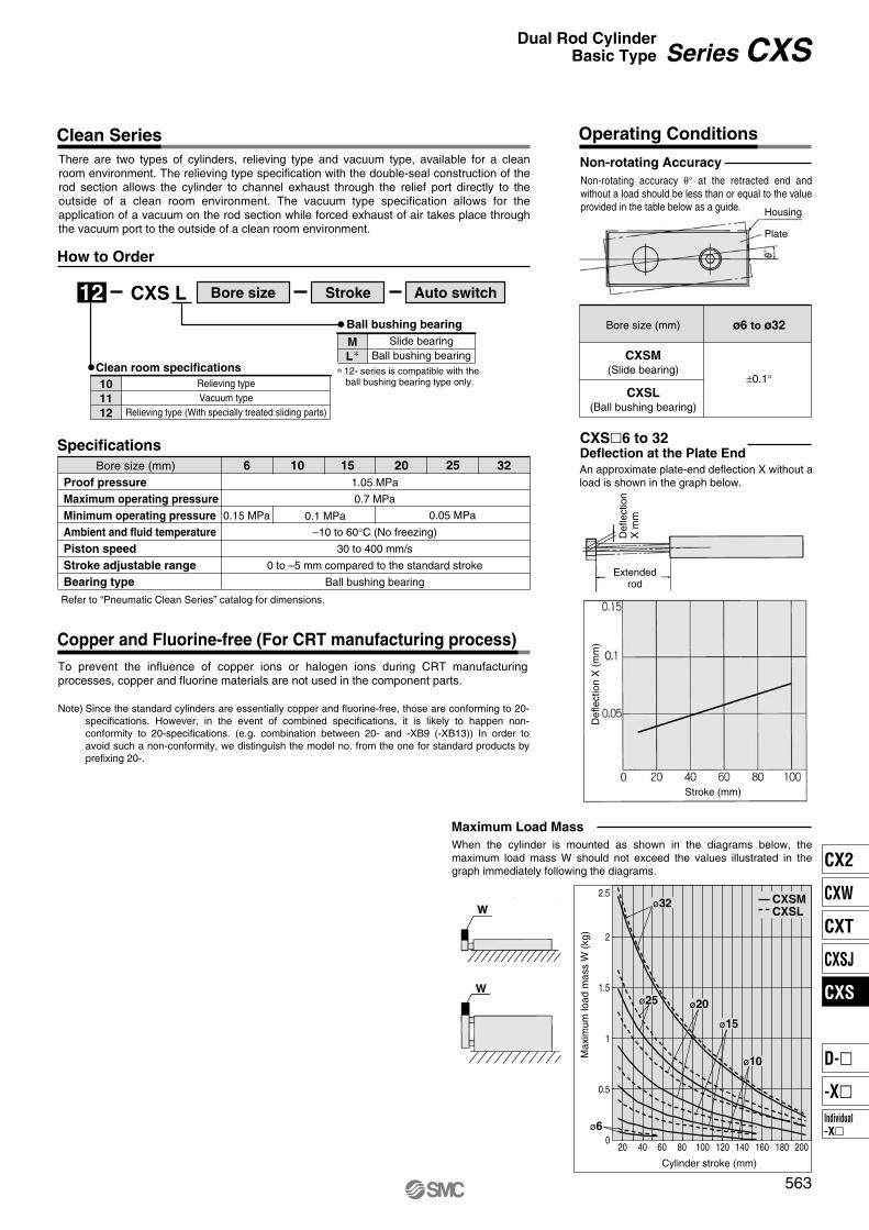
There are two types of cylinders, relieving type and vacuum type, available for a clean room environment. The relieving type specification with the double-seal construction of the rod section allows the cylinder to channel exhaust through the relief port directly to the outside of a clean room environment. The vacuum type specification allows for the application of a vacuum on the rod section while forced exhaust of air takes place through the vacuum port to the outside of a clean room environment.
Bore size Stroke Auto switch
Bore size (mm)Proof pressure
Maximum operating pressure
Minimum operating pressure
Ambient and fluid temperature
Piston speed
Stroke adjustable range
Bearing type
Refer to “Pneumatic Clean Series” catalog for dimensions.
1.05 MPa
0.7 MPa
–10 to 60°C (No freezing)
30 to 400 mm/s
0 to –5 mm compared to the standard stroke
Ball bushing bearing
0.15 MPa 0.05 MPa0.1 MPa
To prevent the influence of copper ions or halogen ions during CRT manufacturing processes, copper and fluorine materials are not used in the component parts.
Since the standard cylinders are essentially copper and fluorine-free, those are conforming to 20- specifications. However, in the event of combined specifications, it is likely to happen non-conformity to 20-specifications. (e.g. combination between 20- and -XB9 (-XB13)) In order to avoid such a non-conformity, we distinguish the model no. from the one for standard products by prefixing 20-.
Note)
Non-rotating accuracy θ° at the retracted end and without a load should be less than or equal to the value provided in the table below as a guide. Housing
Plate
Bore size (mm) ø6 to ø32
±0.1°
CXSM
(Slide bearing)
CXSL
(Ball bushing bearing)
An approximate plate-end deflection X without a load is shown in the graph below.
Def
lect
ion
X m
m
Extendedrod
Def
lect
ion
X (
mm
)
Stroke (mm)
When the cylinder is mounted as shown in the diagrams below, the maximum load mass W should not exceed the values illustrated in the graph immediately following the diagrams.
CX2
CXW
CXT
CXSJ
CXS
Individual-X�
D-�
-X�
6
10
15
20
25
32
CXSM 6-PSCXSM 10 A PSCXSM 15-PSCXSM 20-PSCXSM 25-PSCXSM 32-PS
CXSM6
CXSM10 CXSM15
CXSM20 to 32
!5
!4
!7 !5
!4
!7
!4 y e !1 !2 q !8
!5 !6 @0@1rw o i!0u!9 t
y e !1 !2 @0 !8 q !4ye!1!2 q !8
@6 @1 r w !3 i !0 !9 u t !6 !7 !5 @6@0@1r w !3i!0!9u t!6
!7 !1 !2e !8 q @4 @2 @5
y!6@3@0 @1r w !3 !0!9ut
564
Series CXS
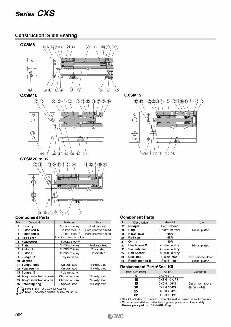
Construction: Slide Bearing
Component Parts Component Parts
Replacement Parts/Seal Kit
No.1
2
3
4
5
6
7
8
9
10
11
12
13
14
15
16
Description MaterialAluminum alloyCarbon steel Carbon steel
Aluminum bearing alloy
Special steel Aluminum alloyAluminum alloy
Aluminum alloyPolyurethane
—Carbon steelCarbon steelPolyurethane
Chromium steelChromium steel
Special steel
NoteHard anodized
Hard chrome platedHard chrome plated
Hard anodizedChromatedChromated
Nickel platedNickel plated
Nickel platedNickel platedNickel plated
Housing
Piston rod A
Piston rod B
Rod cover
Head cover
Plate
Piston A
Piston B
Bumper A
Magnet
Bumper bolt
Hexagon nut
Bumper B
Hexagon socket head cap screw
Hexagon socket head set screw
Retaining ring
Note 1) Stainless steel for CXSM6.Note 2) Anodized aluminum alloy for CXSM6.
(2)
(1)
(1)
No.17
18
19
20
21
22
23
24
25
26
Description MaterialPolyurethane
Chromium steelNBRNBRNBR
Aluminum alloyAluminum alloyAluminum alloySpecial steelSpecial steel
Note
Nickel plated
Nickel plated
Hard chrome platedNickel plated
Bumper
Plug
Piston seal
Rod seal
O-ring
Head cover B
Seal retainer
Port spacer
Steel ball
Retaining ring B
Bore size (mm) Kit no. Contents
Set of nos. above!9, @0 and @1
∗ Seal kit includes !9, @0 and @1. Order the seal kit, based on each bore size.∗ Since the seal kit does not include a grease pack, order it separately. Grease pack part no.: GR-S-010 (10 g)
CXSL 6 – PSCXSL 10 B PSCXSL 15 A PSCXSL 20 A PSCXSL 25 A PSCXSL 32 A PS
6
10
15
20
25
32
CXSL6
CXSL10 CXSL15
CXSL20 to 32
!5
!4 @0
@0
!4
@0
!4ye!1!2q @1
!5!6@3@4r!8w!7o i!0u@2t
y e !1 !2 @3 @1 q
!5@9 @4 rw!8 !9 !3 i!0 @2 ut!6
!1 !2e @1 q @7 @5 @8
y!6@6 @3r !8@4 !9 w !3 !0 @2ut
!4ye!1!2 q @1
@0!5@9@3@4r!8w!9!3i!0@2ut!6
565
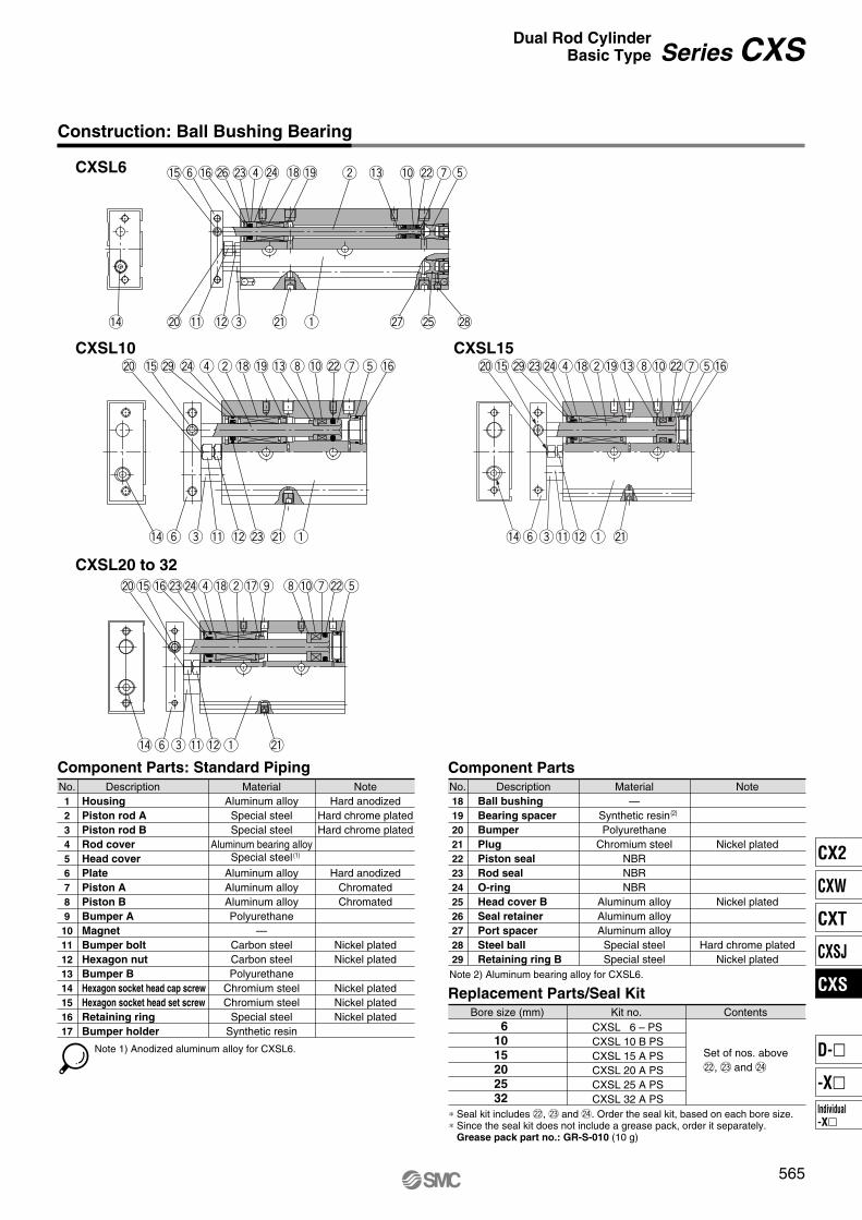
Construction: Ball Bushing Bearing
Component Parts: Standard Piping Component Parts
Replacement Parts/Seal Kit
Series CXSDual Rod Cylinder
Basic Type
No.1
2
3
4
5
6
7
8
9
10
11
12
13
14
15
16
17
Description MaterialAluminum alloySpecial steelSpecial steel
Aluminum bearing alloySpecial steel
Aluminum alloyAluminum alloyAluminum alloyPolyurethane
—Carbon steelCarbon steelPolyurethane
Chromium steelChromium steel
Special steelSynthetic resin
NoteHard anodized
Hard chrome platedHard chrome plated
Hard anodizedChromatedChromated
Nickel platedNickel plated
Nickel platedNickel platedNickel plated
Housing
Piston rod A
Piston rod B
Rod cover
Head cover
Plate
Piston A
Piston B
Bumper A
Magnet
Bumper bolt
Hexagon nut
Bumper B
Hexagon socket head cap screw
Hexagon socket head set screw
Retaining ring
Bumper holder
(1)
Note 1) Anodized aluminum alloy for CXSL6.
No.18
19
20
21
22
23
24
25
26
27
28
29
Description Material—
Synthetic resinPolyurethane
Chromium steelNBRNBRNBR
Aluminum alloyAluminum alloyAluminum alloySpecial steelSpecial steel
Note
Nickel plated
Nickel plated
Hard chrome platedNickel plated
Ball bushing
Bearing spacer
Bumper
Plug
Piston seal
Rod seal
O-ring
Head cover B
Seal retainer
Port spacer
Steel ball
Retaining ring B
(2)
Note 2) Aluminum bearing alloy for CXSL6.
Bore size (mm) Kit no. Contents
Set of nos. above@2, @3 and @4
∗ Seal kit includes @2, @3 and @4. Order the seal kit, based on each bore size.∗ Since the seal kit does not include a grease pack, order it separately. Grease pack part no.: GR-S-010 (10 g)
CX2
CXW
CXT
CXSJ
CXS
Individual-X�
D-�
-X�

(mm)
Model
CXS�6-10
CXS�6-20
CXS�6-30
CXS�6-40
CXS�6-50
Stroke
10
20
30
40
50
Z
15
20
25
30
35
S
23
33
43
53
63
SS
55
65
75
85
95
ZZ
68.5
78.5
88.5
98.5
108.5
2 x M5 x 0.8 thread depth 4.5(Piping port) (Opposite side: Same)
2 x M3 x 0.5 thread depth 4.5(Opposite side: Same)
2 x ø3.4 through2 x ø6.5 counterbore depth 3.3
2 x M3 x 0.5(Through-hole)
2 x M3 x 0.5(Through-hole)
2 x M5 x 0.8 thread depth 4.5 (Piping port) IN
OUT
8
13
SS (45 + ST)
3537
28
10
ø4
(13)
6.3 5
16
28±0
.2
±0.2
1
22.5
3
5.5
2.75
ZZ (58.5 + ST)ST
16
141
7
8
22.7
6
6
3 3
3.2
(16)
5.6
11
S (13 + ST)
Z (10 + 1/2ST)
Z (10 + 1/2ST)
Dimensions: ø6
566
Series CXS
GQ
Q5
1
Stroke
1
A C
B
D
E
ZLI
Q
ZL
8R
ZZG
±0.2
±0.2
±0.2
GH
I
J 9 SS
ZL
øN
N
P
6.3
5
V (Opposite side: Same)
N
M
F (Through-hole)
N U
2 x 2 x M5 x 0.8 thread depth 4.5(Piping port) (Opposite side: Same)
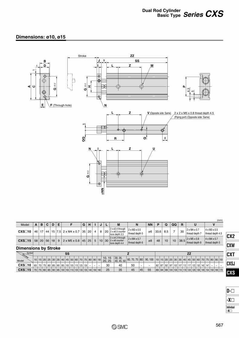
(mm)
Model
CXS�10
CXS�15
A
46
58
B
17
20
C
44
56
D
15
18
E
7.5
9
F
2 x M4 x 0.7
2 x M5 x 0.8
G
35
45
H
20
25
I
4
5
J
8
10
L
20
30
2 x M3 x 0.5thread depth 5
2 x M4 x 0.7thread depth 6
NN
ø6
ø8
P
33.6
48
Q
8.5
10
7
10
R
30
38.5
2 x M4 x 0.7thread depth 7
2 x M5 x 0.8thread depth 8
4 x M3 x 0.5thread depth 4.5
4 x M4 x 0.7thread depth 5
M
2 x ø3.4 through2 x ø6.5 counter-bore depth 3.32 x ø4.3 through2 x ø8 counter-bore depth 4.4
Dimensions by StrokeSymbolStroke
Model
CXS�10
CXS�15
SS Z ZZ
10
65
70
15
70
75
20
75
80
25
80
85
30
85
90
35
90
95
40
95
100
45
100
105
50
105
110
60
115
120
70
125
130
75
130
135
80
–
140
90
–
150
100
–
160
10, 1520, 25
30, 35, 40, 45, 50 60, 70, 75
30
25
40
35
50
45
80
–
45
90, 100
–
55
10
82
89
15
87
94
20
92
99
25
97
104
30
102
109
35
107
114
40
112
119
45
117
124
50
122
129
60
132
139
70
142
149
75
147
154
80
–
159
90
–
169
100
–
179
Dimensions: ø10, ø15
N U V
567
Series CXSDual Rod Cylinder
Basic Type
CX2
CXW
CXT
CXSJ
CXS
Individual-X�
D-�
-X�
TT
QT
UR
NN
G
ZLI
G
ZL
E
A C1
B
1 D
P
6.3 5
ZZ
SSK
ZL
Stroke
J
I
G
H
W
F (Through-hole) N
N
UU (Piping port) (Opposite side: Same)
V (Opposite side: Same)
M
±0.2
±0.2
±0.2
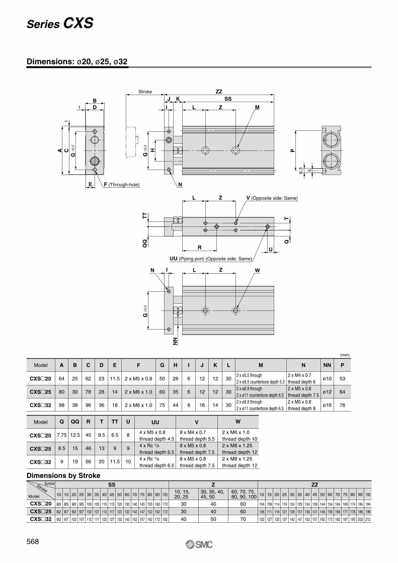
Dimensions by StrokeSymbolStroke
Model
CXS�20
CXS�25
CXS�32
SS Z ZZ
10
80
82
92
15
85
87
97
20
90
92
102
25
95
97
107
30
100
102
112
35
105
107
117
40
110
112
122
45
115
117
127
50
120
122
132
60
130
132
142
70
140
142
152
75
145
147
157
80
150
152
162
90
160
162
172
100
170
172
182
10, 15,20, 25
30, 35, 40,45, 50
60, 70, 75, 80, 90, 100
30
30
40
40
40
50
60
60
70
10
104
106
122
15
109
111
127
20
114
116
132
25
119
121
137
30
124
126
142
35
129
131
147
40
134
136
152
45
139
141
157
50
144
146
162
60
154
156
172
70
164
166
182
75
169
171
187
80
174
176
192
90
184
186
202
100
194
196
212
(mm)
Model
CXS�20
CXS�25
CXS�32
Model
CXS�20
CXS�25
CXS�32
A
64
80
98
B
25
30
38
C
62
78
96
D
23
28
36
E
11.5
14
18
F
2 x M5 x 0.8
2 x M6 x 1.0
2 x M6 x 1.0
G
50
60
75
H
28
35
44
I
6
6
8
J
12
12
16
K
12
12
14
L
30
30
30
M N P
53
64
76
NN
ø10
ø12
ø16
2 x ø5.5 through2 x ø9.5 counterbore depth 5.32 x ø6.9 through2 x ø11 counterbore depth 6.32 x ø6.9 through2 x ø11 counterbore depth 6.3
2 x M4 x 0.7thread depth 62 x M5 x 0.8thread depth 7.52 x M5 x 0.8thread depth 8
Q
7.75
8.5
9
12.5
15
19
R
45
46
56
T
9.5
13
20
TT
6.5
9
11.5
U
8
9
10
UU V
4 x M5 x 0.8thread depth 4.54 x Rc 1/8thread depth 6.54 x Rc 1/8thread depth 6.5
8 x M4 x 0.7thread depth 5.58 x M5 x 0.8thread depth 7.58 x M5 x 0.8thread depth 7.5
2 x M6 x 1.0thread depth 102 x M8 x 1.25thread depth 122 x M8 x 1.25thread depth 12
W
Dimensions: ø20, ø25, ø32
568
Series CXS
6
0.7 0.2
1.2 0.7
10 15 20 25 32
A
B
A
C
D
∗ Normally closed (NC = b contact), solid state auto switch (D-Y7G/Y7H type) are also available. For details, refer to page 1748.
569
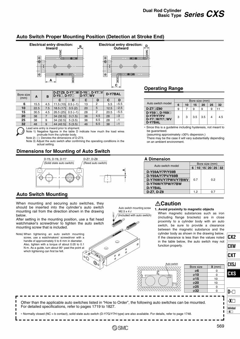
Auto Switch Proper Mounting Position (Detection at Stroke End)
Electrical entry direction: Inward
Electrical entry direction: Outward
Operating Range
Dimensions for Mounting of Auto Switch
Auto Switch Mounting
Other than the applicable auto switches listed in “How to Order”, the following auto switches can be mounted.For detailed specifications, refer to pages 1719 to 1827.
Series CXSDual Rod Cylinder
Basic Type
6
10
15
20
25
32
Bore size(mm)
15.522.530.5383848
A
4.57.54.5799
C
11.5 (10)18.5 (17)26.5 (25)34 (32.5)34 (32.5)44 (42.5)
D
0.5 (–1)3.5 (2)
0.5 (–1)3 (1.5)5 (3.5)5 (3.5)
C
132028363646
D C
5.512.520.5282838
DB
D-Z7/Z8, D-Y7�WD-Y5�, D-Y7�
D-Y6�, D-Y7�VD-Y7�WV
D-Y7BAL
Lead wire entry is inward prior to shipment.Note 1) Negative figures in the table D indicate how much the load wires
protrude from the cylinder body.Note 2) ( ): Denotes the dimensions of D-Z73.Note 3) Adjust the auto switch after confirming the operating conditions in the
actual setting.
–5.5–2.5–5.5–3–1–1
2524.56.56.5
D-Z7�/Z80
D-Y59�, D-Y69�D-Y7P/Y7PVD-Y7�W/Y7�WVD-Y7BAL
Auto switch modelBore size (mm)
6 10 15 20 25 32
9 7 9 9 9 11
3 3 3.5 3.5 4 4.5
∗ Since this is a guideline including hysteresis, not meant to be guaranteed. (assuming approximately ±30% dispersion.)There may be the case it will vary substantially depending on an ambient environment.
D-Z7, D-Z8(Reed auto switch)
D-Y5, D-Y6, D-Y7(Solid state auto switch)
D-Y59A/Y7P/Y59B
D-Y69A/Y7PV/Y69B
D-Y7NWV/Y7PWV/Y7BWV
D-Y7NW/Y7PW/Y7BW
D-Y7BAL
D-Z7, D-Z8
Bore size (mm)A Dimension
Auto switch model
When mounting and securing auto switches, they should be inserted into the cylinder’s auto switch mounting rail from the direction shown in the drawing below. After setting in the mounting position, use a flat head watchmaker's screwdriver to tighten the auto switch mounting screw that is included.
When tightening an auto switch mounting screw, use a watchmakers’ screwdriver with a handle of approximately 5 to 6 mm in diameter. Also, tighten with a torque of about 0.05 to 0.1 N·m. As a guide, turn about 90° past the point at which tightening can first be felt.
Note)
Auto switch mounting screwM2.5 x 4 l(Included with auto switch)
1. Avoid proximity to magnetic objects
When magnetic substances such as iron (including flange brackets) are in close proximity to a cylinder body with an auto switch, be sure to provide a clearance between the magnetic substance and the cylinder body as shown in the drawing below. If the clearance is less than the values noted in the table below, the auto switch may not function properly.
Caution
Auto switchBore size
00
101000
ø6
ø10
ø15
ø20
ø25
ø32
X (mm)
CX2
CXW
CXT
CXSJ
CXS
Individual-X�
D-�
-X�
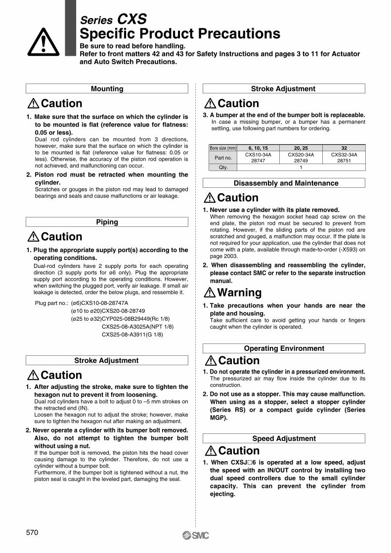
Operating Environment
Speed Adjustment
570
Series CXSSpecific Product PrecautionsBe sure to read before handling.
Refer to front matters 42 and 43 for Safety Instructions and pages 3 to 11 for Actuator
and Auto Switch Precautions.
Mounting
Caution
Caution
Caution
Caution
1. Make sure that the surface on which the cylinder is
to be mounted is flat (reference value for flatness:
0.05 or less).Dual rod cylinders can be mounted from 3 directions, however, make sure that the surface on which the cylinder is to be mounted is flat (reference value for flatness: 0.05 or less). Otherwise, the accuracy of the piston rod operation is not achieved, and malfunctioning can occur.
2. Piston rod must be retracted when mounting the
cylinder.Scratches or gouges in the piston rod may lead to damaged bearings and seals and cause malfunctions or air leakage.
1. Plug the appropriate supply port(s) according to the
operating conditions.
Dual-rod cylinders have 2 supply ports for each operating direction (3 supply ports for ø6 only). Plug the appropriate supply port according to the operating conditions. However, when switching the plugged port, verify air leakage. If small air leakage is detected, order the below plugs, and ressemble it.
Piping
Caution
Caution
Caution
(ø6)CXS10-08-28747A(ø10 to ø20)CXS20-08-28749(ø25 to ø32)CYP025-08B29449(Rc 1/8)
CXS25-08-A3025A(NPT 1/8)CXS25-08-A3911(G 1/8)
Plug part no.:
1. After adjusting the stroke, make sure to tighten the
hexagon nut to prevent it from loosening.Dual rod cylinders have a bolt to adjust 0 to –5 mm strokes on the retracted end (IN).Loosen the hexagon nut to adjust the stroke; however, make sure to tighten the hexagon nut after making an adjustment.
2. Never operate a cylinder with its bumper bolt removed.
Also, do not attempt to tighten the bumper bolt
without using a nut.If the bumper bolt is removed, the piston hits the head cover causing damage to the cylinder. Therefore, do not use a cylinder without a bumper bolt.Furthermore, if the bumper bolt is tightened without a nut, the piston seal is caught in the leveled part, damaging the seal.
Stroke Adjustment
Stroke Adjustment
3. A bumper at the end of the bumper bolt is replaceable.In case a missing bumper, or a bumper has a permanent settling, use following part numbers for ordering.
Bore size (mm)
Part no.
Qty.
6, 10, 15
CXS10-34A28747
20, 25
CXS20-34A28749
1
32
CXS32-34A28751
Disassembly and Maintenance
1. Never use a cylinder with its plate removed.When removing the hexagon socket head cap screw on the end plate, the piston rod must be secured to prevent from rotating. However, if the sliding parts of the piston rod are scratched and gouged, a malfunction may occur. If the plate is not required for your application, use the cylinder that does not come with a plate, available through made-to-order (-X593) on page 2003.
2. When disassembling and reassembling the cylinder,
please contact SMC or refer to the separate instruction
manual.
1. Do not operate the cylinder in a pressurized environment.The pressurized air may flow inside the cylinder due to its construction.
2. Do not use as a stopper. This may cause malfunction.
When using as a stopper, select a stopper cylinder
(Series RS) or a compact guide cylinder (Series
MGP).
1. When CXSJ�6 is operated at a low speed, adjust
the speed with an IN/OUT control by installing two
dual speed controllers due to the small cylinder
capacity. This can prevent the cylinder from
ejecting.
Warning1. Take precautions when your hands are near the
plate and housing.Take sufficient care to avoid getting your hands or fingers caught when the cylinder is operated.
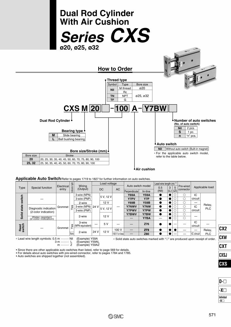
CXS M 100 A20
M
L
Dual Rod Cylinder Number of auto switches(No. of auto switch)
Y7BW
Applicable Auto Switch/Refer to pages 1719 to 1827 for further information on auto switches.
ACDC
Lead wire length (m) ∗
5 V
5 V, 12 V
12 V
5 V, 12 V
12 V
24 V
Z76
Z73
Y59A
Y7P
Y59B
Y7NW
Y7PW
Y7BW
Y7BA
Y69A
Y7PV
Y69B
Y7NWV
Y7PWV
Y7BWV
100 V24 V 12 V
Z73
Z80
571
Dual Rod CylinderWith Air Cushion
Series CXSø20, ø25, ø32
How to Order
Thread type
Bearing type
Slide bearingBall bushing bearing
Bore size/Stroke (mm)
20, 25, 30, 35, 40, 45, 50, 60, 70, 75, 80, 90, 10025, 30, 35, 40, 45, 50, 60, 70, 75, 80, 90, 100
Air cushion
Auto switch
100 V or less
Load voltageWiring
(Output)Pre-wiredconnector
Applicable load
Bore sizeø20
ø25, ø32
TypeM thread
RcNPT
G
Symbol
Nil
TN
TF
Bore size20
25, 32
Stroke
Nil
S
n
2 pcs. 1 pc.
“n” pcs.
Nil Without auto switch (Built-in magnet)
For the applicable auto switch model, refer to the table below.
∗
Special functionType Electricalentry
Indi
cato
r lig
htY
esY
es
Grommet
Grommet
Ree
dsw
itc
hS
olid
sta
te s
wit
ch
Water resistant(2-color indication)
Diagnostic indication(2-color indication)
—
—
None
3-wire (NPN)3-wire (PNP)
2-wire3-wire (NPN)3-wire (PNP)
2-wire
2-wire
3-wire(NPN equivalent) — —
—
—
——
—
—
—
—
—
——
ICcircuit
ICcircuit
ICcircuit
IC circuit
—
—
—
—
Relay, PLC
Relay, PLC
0.5(Nil)
3 (L)
5 (Z)
Auto switch model
Perpendicular In-line
• Since there are other applicable auto switches than listed, refer to page 569 for details.• For details about auto switches with pre-wired connector, refer to pages 1784 and 1785.• Auto switches are shipped together (not assembled).
∗ Solid state auto switches marked with “�” are produced upon receipt of order.∗ Lead wire length symbols: 0.5 m ·········· Nil (Example) Y59A3 m ·········· L (Example) Y59AL m ·········· Z (Example) Y59AZ
CX2
CXW
CXT
CXSJ
CXS
Individual-X�
D-�
-X�
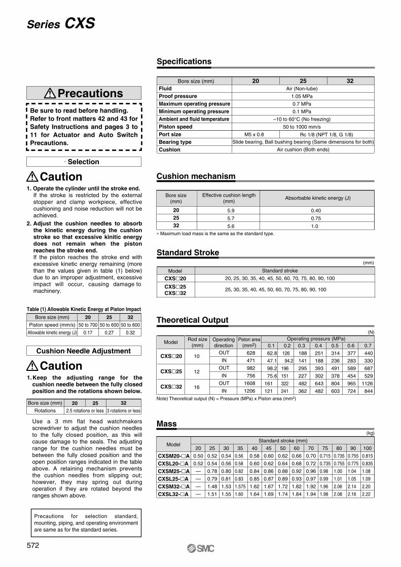
Mass
628
471
982
756
1608
1206
0.2
126
94.2
196
151
322
241
0.3
188
141
295
227
482
362
0.4
251
188
393
302
643
482
0.5
314
236
491
378
804
603
0.6
377
283
589
454
965
724
0.7
440
330
687
529
1126
844
0.1
62.8
47.1
98.2
75.6
161
121
OUT
IN
OUT
IN
OUT
IN
10
12
16
20
0.50
0.52
—
—
—
—
25
0.52
0.54
0.78
0.79
1.48
1.51
30
0.54
0.56
0.80
0.81
1.53
1.55
35
0.56
0.58
0.82
0.83
1.575
1.60
40
0.58
0.60
0.84
0.85
1.62
1.64
45
0.60
0.62
0.86
0.87
1.67
1.69
50
0.62
0.64
0.88
0.89
1.72
1.74
60
0.66
0.68
0.92
0.93
1.82
1.84
70
0.70
0.72
0.96
0.97
1.92
1.94
75
0.715
0.735
0.98
0.99
1.96
1.98
80
0.735
0.755
1.00
1.01
2.06
2.08
90
0.755
0.775
1.04
1.05
2.14
2.16
100
0.815
0.835
1.08
1.09
2.20
2.22
Specifications
32
5.9
5.7
5.6
0.40
0.75
1.0
20
25
32
Cushion Needle Adjustment
(N)
2520
572
Series CXS
Precautions
Be sure to read before handling.
Refer to front matters 42 and 43 for
Safety Instructions and pages 3 to
11 for Actuator and Auto Switch
Precautions.
Selection
Caution
Caution
1. Operate the cylinder until the stroke end.
If the stroke is restricted by the external stopper and clamp workpiece, effective cushioning and noise reduction will not be achieved.
2. Adjust the cushion needles to absorb
the kinetic energy during the cushion
stroke so that excessive kinitic energy
does not remain when the piston
reaches the stroke end.
If the piston reaches the stroke end with excessive kinetic energy remaining (more than the values given in table (1) below) due to an improper adjustment, excessive impact will occur, causing damage to machinery.
Table (1) Allowable Kinetic Energy at Piston Impact
Bore size (mm)
Piston speed (mm/s)
Allowable kinetic energy (J)
25
50 to 600
0.27
20
50 to 700
0.17
32
50 to 600
0.32
1.Keep the adjusting range for the
cushion needle between the fully closed
position and the rotations shown below.
Bore size (mm)
Rotations
2520 32
3 rotations or less2.5 rotations or less
Use a 3 mm flat head watchmakers screwdriver to adjust the cushion needles to the fully closed position, as this will cause damage to the seals. The adjusting range for the cushion needles must be between the fully closed position and the open position ranges indicated in the table above. A retaining mechanism prevents the cushion needles from slipping out; however, they may spring out during operation if they are rotated beyond the ranges shown above.
Precautions for selection standard, mounting, piping, and operating environment are same as for the standard series.
Fluid
Proof pressure
Maximum operating pressure
Minimum operating pressure
Ambient and fluid temperature
Piston speed
Port size
Bearing type
Cushion
Bore size (mm)Air (Non-lube)
1.05 MPa
0.7 MPa
0.1 MPa
–10 to 60°C (No freezing)
50 to 1000 mm/s
M5 x 0.8 Rc 1/8 (NPT 1/8, G 1/8)Slide bearing, Ball bushing bearing (Same dimensions for both)
Air cushion (Both ends)
Cushion mechanism
Absorbable kinetic energy (J)Effective cushion length(mm)
Bore size(mm)
Standard Stroke
CXS�20
CXS�25
CXS�32
Model Standard stroke
20, 25, 30, 35, 40, 45, 50, 60, 70, 75, 80, 90, 100
(mm)
25, 30, 35, 40, 45, 50, 60, 70, 75, 80, 90, 100
Theoretical Output
CXS�20
CXS�25
CXS�32
Model Operatingdirection
Operating pressure (MPa)Rod size(mm)
Piston area(mm2)
Note) Theoretical output (N) = Pressure (MPa) x Piston area (mm2)
Model
CXSM20-�A
CXSL20-�A
CXSM25-�A
CXSL25-�A
CXSM32-�A
CXSL32-�A
Standard stroke (mm)
(kg)
∗ Maximum load mass is the same as the standard type.
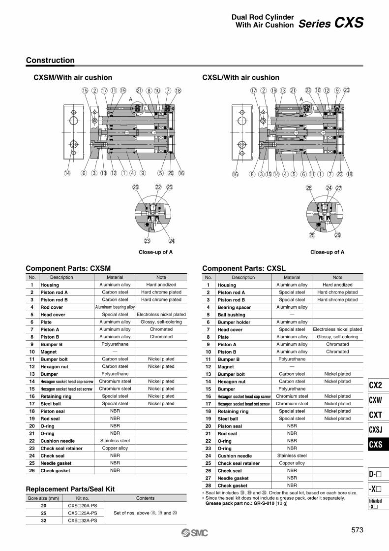
!4 !3y e !2
!1
q r
i
@5
@1
@4
@2
@3
t
!8!5 w !9 !0!7 u
o !6@0 !4
!3
ye
!2!0
!1 q!6 i t
@8
@5 @6
@4
@3
@7
@0
!5
w @1!9
r
!7
u
o
!8@2
@6
573
CXSM/With air cushion
Construction
CXSL/With air cushion
A A
Close-up of A Close-up of A
Component Parts: CXSM
Series CXSDual Rod Cylinder
With Air Cushion
No. Description
Housing
Piston rod A
Piston rod B
Rod cover
Head cover
Plate
Piston A
Piston B
Bumper B
Magnet
Bumper bolt
Hexagon nut
Bumper
Hexagon socket head cap screw
Hexagon socket head set screw
Retaining ring
Steel ball
Piston seal
Rod seal
O-ring
O-ring
Cushion needle
Check seal retainer
Check seal
Needle gasket
Check gasket
Material
Aluminum alloy
Carbon steel
Carbon steel
Aluminum bearing alloy
Special steel
Aluminum alloy
Aluminum alloy
Aluminum alloy
Polyurethane
—
Carbon steel
Carbon steel
Polyurethane
Chromium steel
Chromium steel
Special steel
Special steel
NBR
NBR
NBR
NBR
Stainless steel
Copper alloy
NBR
NBR
NBR
Note
Hard anodized
Hard chrome plated
Hard chrome plated
Electroless nickel plated
Glossy, self-coloring
Chromated
Chromated
Nickel plated
Nickel plated
Nickel plated
Nickel plated
Nickel plated
Nickel plated
1
2
3
4
5
6
7
8
9
10
11
12
13
14
15
16
17
18
19
20
21
22
23
24
25
26
Replacement Parts/Seal Kit
Kit no.
CXS�20A-PS
CXS�25A-PS
CXS�32A-PS
Bore size (mm)
20
25
32
Contents
Set of nos. above !8, !9 and @0
Component Parts: CXSL
No. Description
Housing
Piston rod A
Piston rod B
Bearing spacer
Ball bushing
Bumper holder
Head cover
Plate
Piston A
Piston B
Bumper B
Magnet
Bumper bolt
Hexagon nut
Bumper
Hexagon socket head cap screw
Hexagon socket head set screw
Retaining ring
Steel ball
Piston seal
Rod seal
O-ring
O-ring
Cushion needle
Check seal retainer
Check seal
Needle gasket
Check gasket
Material
Aluminum alloy
Special steel
Special steel
Aluminum alloy
—
Aluminum alloy
Special steel
Aluminum alloy
Aluminum alloy
Aluminum alloy
Polyurethane
—
Carbon steel
Carbon steel
Polyurethane
Chromium steel
Chromium steel
Special steel
Special steel
NBR
NBR
NBR
NBR
Stainless steel
Copper alloy
NBR
NBR
NBR
Note
Hard anodized
Hard chrome plated
Hard chrome plated
Electroless nickel plated
Glossy, self-coloring
Chromated
Chromated
Nickel plated
Nickel plated
Nickel plated
Nickel plated
Nickel plated
Nickel plated
1
2
3
4
5
6
7
8
9
10
11
12
13
14
15
16
17
18
19
20
21
22
23
24
25
26
27
28
∗ Seal kit includes !8, !9 and @0. Order the seal kit, based on each bore size.∗ Since the seal kit does not include a grease pack, order it separately. Grease pack part no.: GR-S-010 (10 g)
CX2
CXW
CXT
CXSJ
CXS
Individual-X�
D-�
-X�
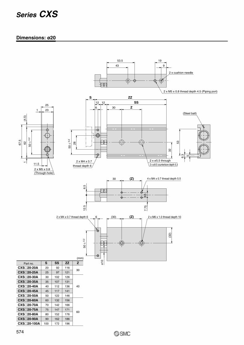
S
20
25
30
35
40
45
50
60
70
75
80
90
100
SS
92
97
102
107
112
117
122
132
142
147
152
162
172
ZZ
116
121
126
131
136
141
146
156
166
171
176
186
196
Z
30
40
60
S
Z
SS
ZZ
(Z)
(Z)
574
Series CXS
Dimensions: ø20
(Through-hole)
50 ±
0.2
(4.5
)
2 x M5 x 0.8
231
25
62
11.5
67.5
1
53.5 19
43 9
2 x M5 x 0.8 thread depth 4.5 (Piping port)
2 x cushion needle
56.3
53
32
(Steel ball)
2 x ø5.5 through2 x ø9.5 counterbore depth 5.3
50 ±
0.2
2 x M4 x 0.7
thread depth 6
28
6
12
30
12
30
9.5
7.75
6.5
12.5
4 x M4 x 0.7 thread depth 5.5
2 x M6 x 1.0 thread depth 106 (30)
ø10
(32)
50 ±
0.2
2 x M4 x 0.7 thread depth 6
CXS�20-20A
CXS�20-25A
CXS�20-30A
CXS�20-35A
CXS�20-40A
CXS�20-45A
CXS�20-50A
CXS�20-60A
CXS�20-70A
CXS�20-75A
CXS�20-80A
CXS�20-90A
CXS�20-100A
Part no.
(mm)

S
25
30
35
40
45
50
60
70
75
80
90
100
SS
100
105
110
115
120
125
135
145
150
155
165
175
ZZ
124
129
134
139
144
149
159
169
174
179
189
199
Z
30
40
60
(Z)
(Z)
60 ±
0.2
Z
ZZS
SS
Note) For port threads TN and TF, only the piping port type varies.
575
Dimensions: ø25
56.3
64
57.5 22
45.5 10
30
1212
6
40
60 ±
0.2
78
281
30
14
81.5
(2.5
)
Series CXSDual Rod Cylinder
With Air Cushion
2 x Rc 1/8 thread depth 6.5 (Piping port)Note)
2 x cushion needle
(Steel ball)
2 x ø6.9 through
2 x ø11 counterbore depth 6.3thread depth 7.5
2 x M5 x 0.8
35
60 ±
0.2
2 x M6 x 1.0 (Through-hole)
30
138.
5
159
(30)6
ø12
(40)
4 x M5 x 0.8 thread depth 7.5
2 x M8 x 1.25thread depth 12
2 x M5 x 0.8
thread depth 7.5
CXS�25-25A
CXS�25-30A
CXS�25-35A
CXS�25-40A
CXS�25-45A
CXS�25-50A
CXS�25-60A
CXS�25-70A
CXS�25-75A
CXS�25-80A
CXS�25-90A
CXS�25-100A
Part no.
(mm)
1
CX2
CXW
CXT
CXSJ
CXS
Individual-X�
D-�
-X�
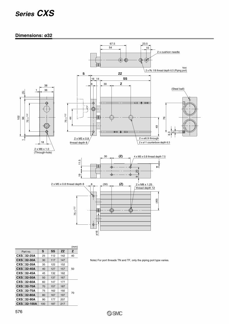
S
25
30
35
40
45
50
60
70
75
80
90
100
SS
112
117
122
127
132
137
147
157
162
167
177
187
ZZ
142
147
152
157
162
167
177
187
192
197
207
217
Z
40
50
70
Z
SS
ZZS
(Z)
(Z)
1911
.5
T
576
Series CXS
Dimensions: ø32
308
16 14
44
67.5 23.554 10
5
76
6.3
96
18
361
38
102
(5)
1
49
75 ±
0.2
75 ±
0.2
2 x M6 x 1.0(Through-hole)
thread depth 8
2 x M5 x 0.8 2 x ø6.9 through
2 x ø11 counterbore depth 6.3
2 x Rc 1/8 thread depth 6.5 (Piping port)Note)
2 x cushion needle
(Steel ball)
4 x M5 x 0.8 thread depth 7.5
(30)8
ø16
30
920
(49)
2 x M8 x 1.25thread depth 12
75 ±
0.2
2 x M5 x 0.8 thread depth 8
CXS�32-25A
CXS�32-30A
CXS�32-35A
CXS�32-40A
CXS�32-45A
CXS�32-50A
CXS�32-60A
CXS�32-70A
CXS�32-75A
CXS�32-80A
CXS�32-90A
CXS�32-100A
Part no.
(mm)
Note) For port threads TN and TF, only the piping port type varies.
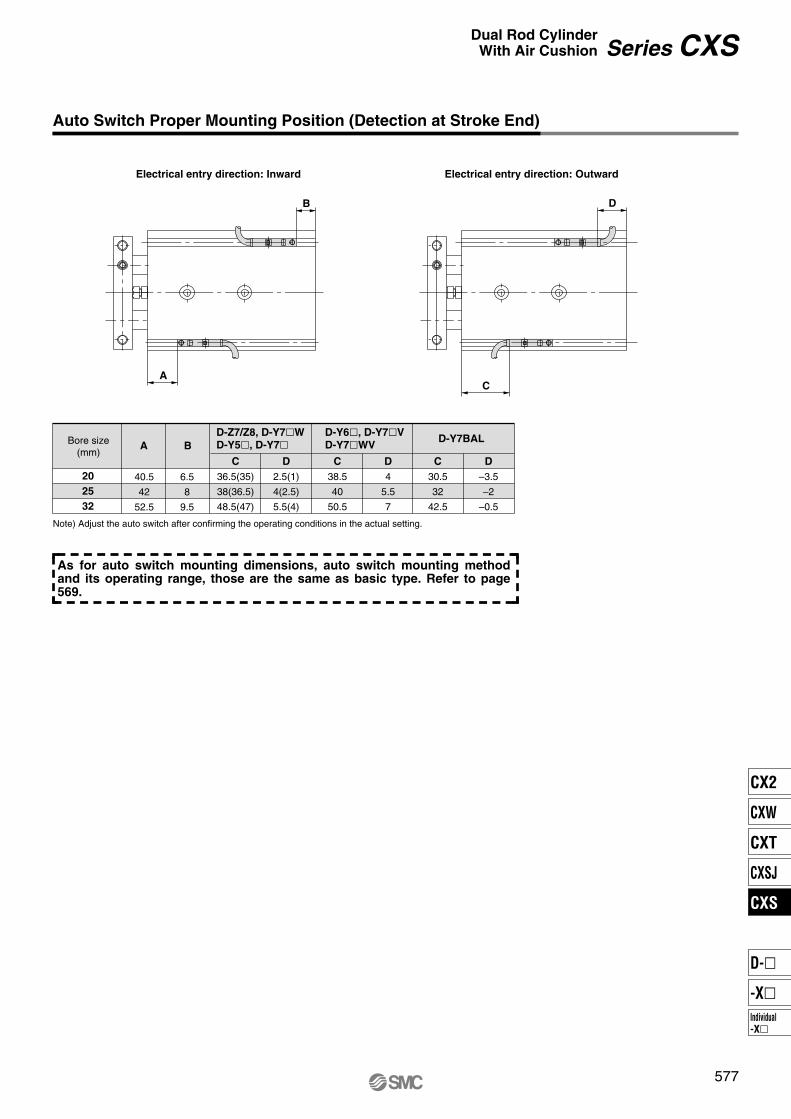
Note) Adjust the auto switch after confirming the operating conditions in the actual setting.
20
25
32
BA
C
36.5(35)
38(36.5)
48.5(47)
40.5
42
52.5
6.5
8
9.5
D
2.5(1)
4(2.5)
5.5(4)
C
38.5
40
50.5
D
4
5.5
7
C
30.5
32
42.5
D
–3.5
–2
–0.5
D
C
B
A
577
Auto Switch Proper Mounting Position (Detection at Stroke End)
Electrical entry direction: Inward Electrical entry direction: Outward
Series CXSDual Rod Cylinder
With Air Cushion
D-Z7/Z8, D-Y7�W
D-Y5�, D-Y7�D-Y6�, D-Y7�V
D-Y7�WVD-Y7BALBore size
(mm)
As for auto switch mounting dimensions, auto switch mounting method and its operating range, those are the same as basic type. Refer to page 569.
CX2
CXW
CXT
CXSJ
CXS
Individual-X�
D-�
-X�
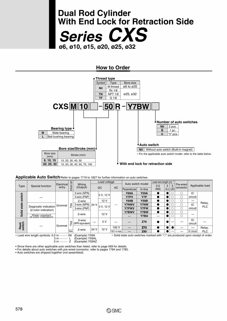
CXS M Y7BW50 R10
M
L
With end lock for retraction side
Z76
Z73
Y59A
Y7P
Y59B
Y7NW
Y7PW
Y7BW
Y7BA
Y69A
Y7PV
Y69B
Y7NWV
Y7PWV
Y7BWV
Z73
Z80
Lead wire length (m) ∗
578
Series CXSø6, ø10, ø15, ø20, ø25, ø32
Wiring(Output)
100 V or less
Load voltagePre-wiredconnector
Applicable load
Dual Rod CylinderWith End Lock for Retraction Side
How to Order
Bearing type
Slide bearingBall bushing bearing
Bore size/Stroke (mm)
Bore size(mm)
10, 20, 30, 40, 5010, 20, 30, 40, 50, 75, 100
Stroke (mm)
6, 10, 15
20, 25, 32
Number of auto switches
2 pcs. 1 pc.
“n” pcs.
Nil
S
n
Auto switch
Nil Without auto switch (Built-in magnet)
∗ For the applicable auto switch model, refer to the table below.
Applicable Auto Switch/Refer to pages 1719 to 1827 for further information on auto switches.
Special functionTypeElectrical
entry
Indi
cato
r lig
htY
esY
es
Grommet
Grommet
Reed
sw
itc
hS
olid
sta
te s
wit
ch
—
—
Water resistant(2-color indication)
Diagnostic indication(2-color indication)
None
3-wire (NPN)3-wire (PNP)
2-wire3-wire (NPN)3-wire (PNP)
2-wire
2-wire
3-wire(NPN equivalent)
ACDC
5 V
5 V, 12 V
12 V
5 V, 12 V
12 V
24 V
—
24 V 12 V100 V
—
—
—
—
——
Auto switch model
Perpendicular In-line0.5(Nil)
3 (L)
5 (Z)
—
—
—
—
——
ICcircuit
ICcircuit
ICcircuit
IC circuit
—
—
—
—
Relay, PLC
Relay, PLC
• Since there are other applicable auto switches than listed, refer to page 569 for details.• For details about auto switches with pre-wired connector, refer to pages 1784 and 1785.• Auto switches are shipped together (not assembled).
∗ Solid state auto switches marked with “ ” are produced upon receipt of order.∗ Lead wire length symbols: 0.5 m ·········· Nil (Example) Y59A3 m ·········· L (Example) Y59AL5 m ·········· Z (Example) Y59AZ
Thread type
Bore sizeø6 to ø20
ø25, ø32
TypeM threadRc 1/8
NPT 1/8G 1/8
Symbol
Nil
TN
TF
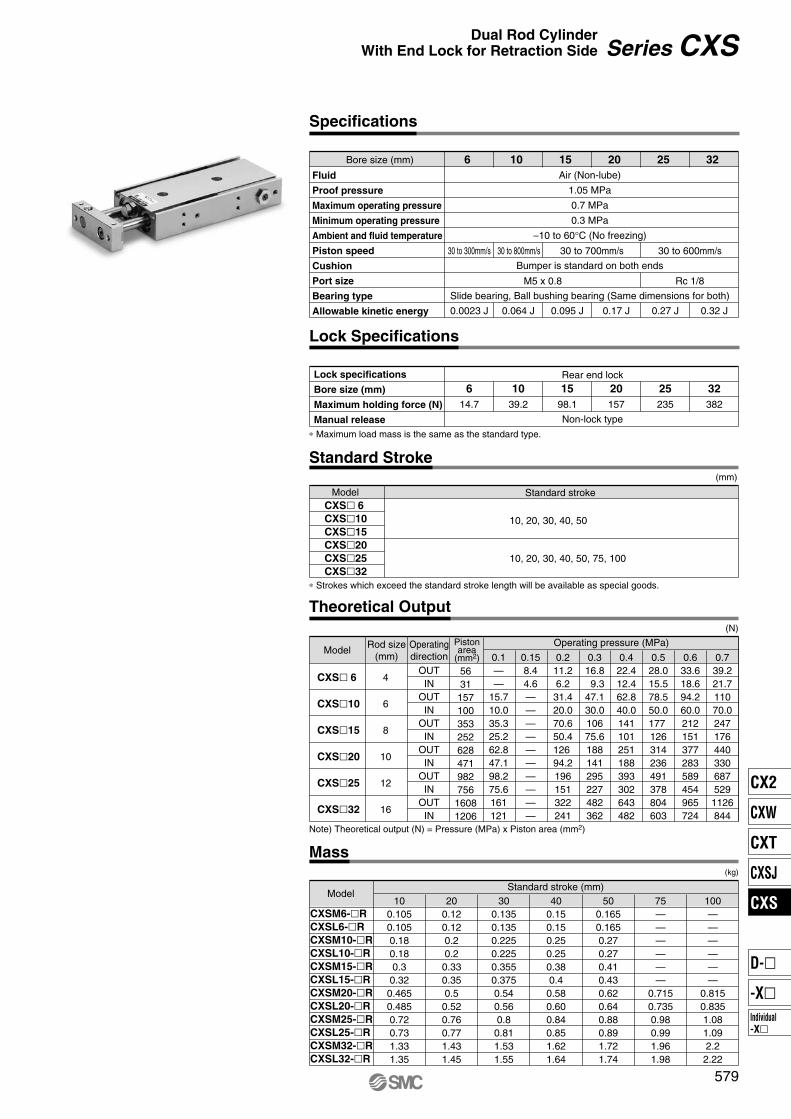
6 10 15 20 25 32
6 10 15 20 25 32
100——————
0.8150.8351.081.092.2
2.22
75——————
0.7150.7350.980.991.961.98
500.1650.1650.270.270.410.430.620.640.880.891.721.74
400.150.150.250.250.380.40.580.600.840.851.621.64
300.1350.1350.2250.2250.3550.3750.540.560.80.811.531.55
200.120.120.20.20.330.350.50.520.760.771.431.45
100.1050.1050.180.180.30.320.4650.4850.720.731.331.35
579
Specifications
∗ Strokes which exceed the standard stroke length will be available as special goods.
Series CXSDual Rod Cylinder
With End Lock for Retraction Side
Fluid
Proof pressure
Maximum operating pressure
Minimum operating pressure
Ambient and fluid temperature
Piston speed
Cushion
Port size
Bearing type
Allowable kinetic energy
Bore size (mm)
30 to 300mm/s 30 to 800mm/s 30 to 700mm/s 30 to 600mm/s
M5 x 0.8 Rc 1/8
0.0023 J 0.064 J 0.095 J 0.17 J 0.27 J 0.32 J
Air (Non-lube)
1.05 MPa
0.7 MPa
0.3 MPa
–10 to 60°C (No freezing)
Bumper is standard on both ends
Slide bearing, Ball bushing bearing (Same dimensions for both)
Lock Specifications
Lock specifications
Bore size (mm)
Maximum holding force (N)
Manual release
Rear end lock
Non-lock type
14.7 98.1 157 235 38239.2
∗ Maximum load mass is the same as the standard type.
Standard Stroke
CXS� 6CXS�10
CXS�15
CXS�20
CXS�25
CXS�32
Model Standard stroke
(mm)
10, 20, 30, 40, 50, 75, 100
10, 20, 30, 40, 50
Theoretical Output
563115710035325262847198275616081206
0.1——
15.710.035.325.262.847.198.275.6161121
0.158.44.6——————————
0.211.26.231.420.070.650.4126 94.2196151322241
0.316.8 9.347.130.010675.6188141295227482362
0.422.412.462.840.0141101251188393302643482
0.528.015.578.550.0177 126314236491378804603
0.633.618.694.260.0212151377283589454965724
0.739.221.711070.0247176440330687529
1126844
OUTIN
OUTIN
OUTIN
OUTIN
OUTIN
OUTIN
4
6
8
10
12
16
(N)
CXS� 6
CXS�10
CXS�15
CXS�20
CXS�25
CXS�32
Model Operatingdirection
Operating pressure (MPa)Rod size(mm)
Pistonarea
(mm2)
Note) Theoretical output (N) = Pressure (MPa) x Piston area (mm2)
Mass(kg)
CXSM6-�R
CXSL6-�R
CXSM10-�R
CXSL10-�R
CXSM15-�R
CXSL15-�R
CXSM20-�R
CXSL20-�R
CXSM25-�R
CXSL25-�R
CXSM32-�R
CXSL32-�R
Standard stroke (mm)Model
CX2
CXW
CXT
CXSJ
CXS
Individual-X�
D-�
-X�
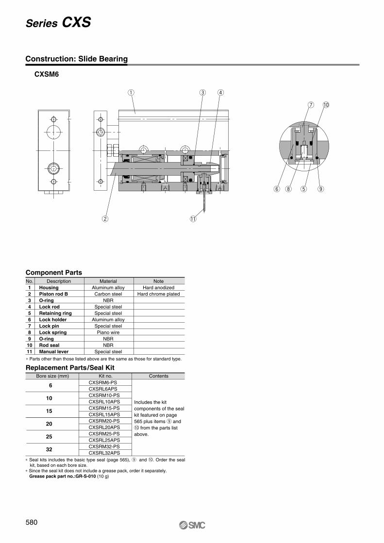
CXSM6
q
6
10
15
20
25
32
CXSRM6-PSCXSRL6APSCXSRM10-PSCXSRL10APSCXSRM15-PSCXSRL15APSCXSRM20-PSCXSRL20APSCXSRM25-PSCXSRL25APSCXSRM32-PSCXSRL32APS
e r
!1
y i t o
u !0
w
580
Series CXS
Construction: Slide Bearing
Component Parts
No.1
2
3
4
5
6
7
8
9
10
11
Description MaterialAluminum alloyCarbon steel
NBRSpecial steelSpecial steel
Aluminum alloySpecial steelPiano wire
NBRNBR
Special steel
NoteHard anodized
Hard chrome platedHousing
Piston rod B
O-ring
Lock rod
Retaining ring
Lock holder
Lock pin
Lock spring
O-ring
Rod seal
Manual lever
∗ Parts other than those listed above are the same as those for standard type.
Replacement Parts/Seal Kit
Bore size (mm) Kit no. Contents
Includes the kit components of the seal kit featured on page 565 plus items o and !0 from the parts list above.
∗ Seal kits includes the basic type seal (page 565), o and !0. Order the seal kit, based on each bore size.
∗ Since the seal kit does not include a grease pack, order it separately.Grease pack part no.:GR-S-010 (10 g)
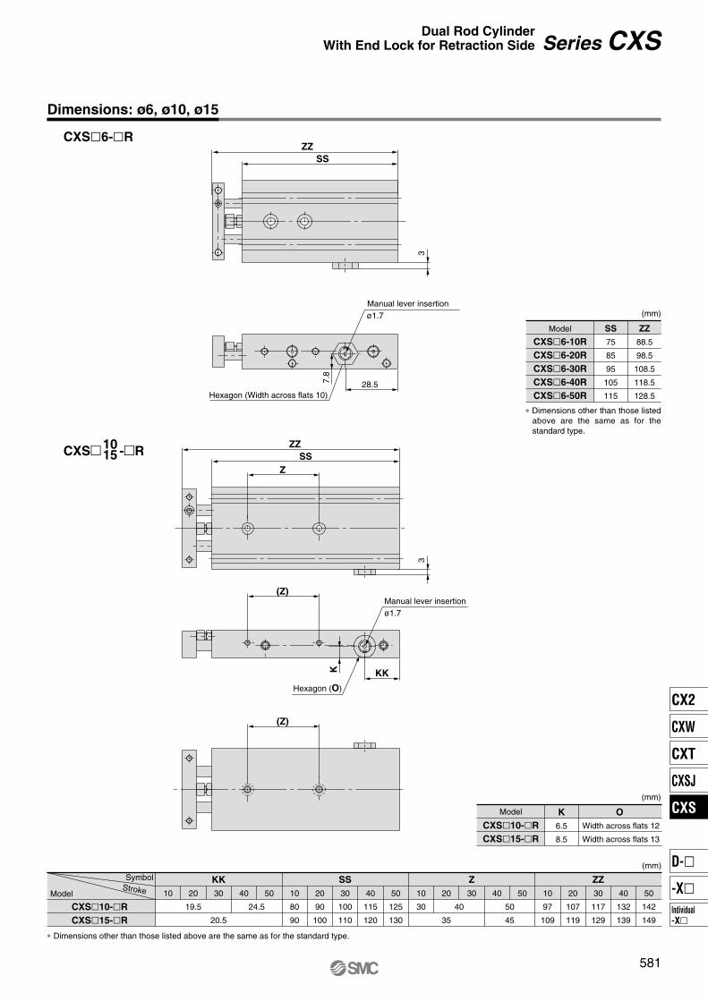
ZZSS
88.5
98.5
108.5
118.5
128.5
75
85
95
105
115
OK
6.5
8.5
ZZZSSKK
50
142
149
40
132
139
30
117
129
20
107
119
10
97
109
50403020
35
10
30
50
125
130
40
115
120
30
100
110
20
90
100
10
80
90
504030
20.5
20
19.5
10
24.5 40 50
45
ZZ
SS
ZZ
SS
Z
(Z)
(Z)
K KK
1015
581
Dimensions: ø6, ø10, ø15
CXS�6-�R
CXS� -�R
3
7.8
28.5
ø1.7Manual lever insertion
Hexagon (Width across flats 10)
3
ø1.7Manual lever insertion
Hexagon (O)
Series CXSDual Rod Cylinder
With End Lock for Retraction Side
Model
CXS�6-10R
CXS�6-20R
CXS�6-30R
CXS�6-40R
CXS�6-50R
(mm)
∗ Dimensions other than those listed above are the same as for the standard type.
Model
CXS�10-�R
CXS�15-�R
Width across flats 12
Width across flats 13
(mm)
CXS�10-�R
CXS�15-�R
Model
SymbolStroke
(mm)
∗ Dimensions other than those listed above are the same as for the standard type.
CX2
CXW
CXT
CXSJ
CXS
Individual-X�
D-�
-X�
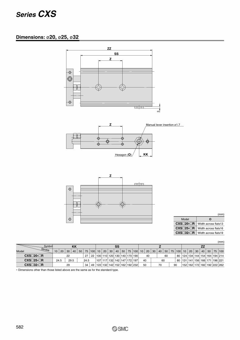
Z
3KK
Z
ZZ
SS
Z
Manual lever insertion ø1.7
Hexagon (O)
Model
CXS�20-�R
CXS�25-�R
CXS�32-�R
O
Width across flats13
Width across flats16
Width across flats19
(mm)
CXS�20-�R
CXS�25-�R
CXS�32-�R
ZZZSSKK
100
190
197
232
50
140
147
162
30
120
132
142
75
170
172
192
40
130
142
152
20
110
117
132
10
100
107
122
100
22
49
75
27
24.5
34
504030
22
29
2010
24.5 29.5
(mm)
100
214
221
262
50
164
171
192
30
144
156
172
75
194
196
222
40
154
166
182
20
134
141
162
10
124
131
152
100
80
80
7550
60
40
70 90
30
40
50
20
40
60
10
∗ Dimensions other than those listed above are the same as for the standard type.
Model
SymbolStroke
Dimensions: ø20, ø25, ø32
582
Series CXS
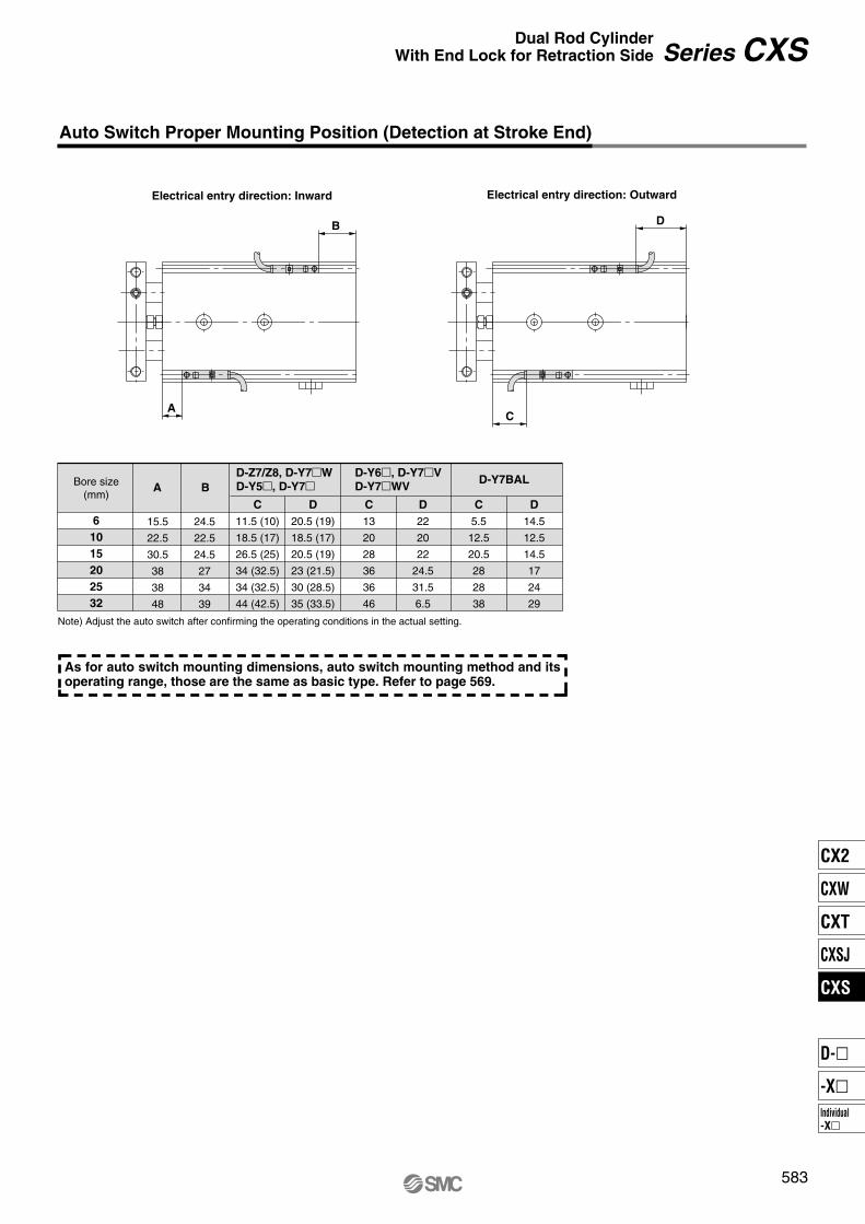
Auto Switch Proper Mounting Position (Detection at Stroke End)
6
10
15
20
25
32
BA
C
11.5 (10)
18.5 (17)
26.5 (25)
34 (32.5)
34 (32.5)
44 (42.5)
15.5
22.5
30.5
38
38
48
24.5
22.5
24.5
27
34
39
D
20.5 (19)
18.5 (17)
20.5 (19)
23 (21.5)
30 (28.5)
35 (33.5)
C
13
20
28
36
36
46
D
22
20
22
24.5
31.5
6.5
C
5.5
12.5
20.5
28
28
38
D
14.5
12.5
14.5
17
24
29
D-Z7/Z8, D-Y7�W
D-Y5�, D-Y7�D-Y6�, D-Y7�V
D-Y7�WVD-Y7BALBore size
(mm)
Electrical entry direction: Inward Electrical entry direction: Outward
A
B
C
D
Note) Adjust the auto switch after confirming the operating conditions in the actual setting.
As for auto switch mounting dimensions, auto switch mounting method and its operating range, those are the same as basic type. Refer to page 569.
583
Series CXSDual Rod Cylinder
With End Lock for Retraction Side
CX2
CXW
CXT
CXSJ
CXS
Individual-X�
D-�
-X�
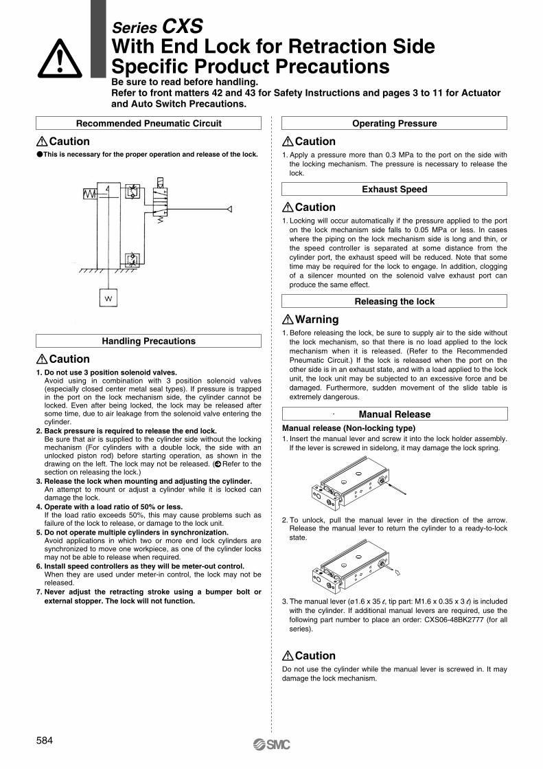
Recommended Pneumatic Circuit Operating Pressure
�This is necessary for the proper operation and release of the lock.
Caution
Handling Precautions
Caution
1. Apply a pressure more than 0.3 MPa to the port on the side with the locking mechanism. The pressure is necessary to release the lock.
Caution
Exhaust Speed
1. Locking will occur automatically if the pressure applied to the port on the lock mechanism side falls to 0.05 MPa or less. In cases where the piping on the lock mechanism side is long and thin, or the speed controller is separated at some distance from the cylinder port, the exhaust speed will be reduced. Note that some time may be required for the lock to engage. In addition, clogging of a silencer mounted on the solenoid valve exhaust port can produce the same effect.
Caution
Releasing the lock
1. Before releasing the lock, be sure to supply air to the side without the lock mechanism, so that there is no load applied to the lock mechanism when it is released. (Refer to the Recommended Pneumatic Circuit.) If the lock is released when the port on the other side is in an exhaust state, and with a load applied to the lock unit, the lock unit may be subjected to an excessive force and be damaged. Furthermore, sudden movement of the slide table is extremely dangerous.
Warning
1. Do not use 3 position solenoid valves.
Avoid using in combination with 3 position solenoid valves (especially closed center metal seal types). If pressure is trapped in the port on the lock mechanism side, the cylinder cannot be locked. Even after being locked, the lock may be released after some time, due to air leakage from the solenoid valve entering the cylinder.
2. Back pressure is required to release the end lock.
Be sure that air is supplied to the cylinder side without the locking mechanism (For cylinders with a double lock, the side with an unlocked piston rod) before starting operation, as shown in the drawing on the left. The lock may not be released. ( Refer to the section on releasing the lock.)
3. Release the lock when mounting and adjusting the cylinder.
An attempt to mount or adjust a cylinder while it is locked can damage the lock.
4. Operate with a load ratio of 50% or less.
If the load ratio exceeds 50%, this may cause problems such as failure of the lock to release, or damage to the lock unit.
5. Do not operate multiple cylinders in synchronization.
Avoid applications in which two or more end lock cylinders are synchronized to move one workpiece, as one of the cylinder locks may not be able to release when required.
6. Install speed controllers as they will be meter-out control.
When they are used under meter-in control, the lock may not be released.
7. Never adjust the retracting stroke using a bumper bolt or
external stopper. The lock will not function.
1. Insert the manual lever and screw it into the lock holder assembly. If the lever is screwed in sidelong, it may damage the lock spring.
2. To unlock, pull the manual lever in the direction of the arrow. Release the manual lever to return the cylinder to a ready-to-lock state.
3. The manual lever (ø1.6 x 35 l, tip part: M1.6 x 0.35 x 3 l) is included with the cylinder. If additional manual levers are required, use the following part number to place an order: CXS06-48BK2777 (for all series).
Manual Release
Manual release (Non-locking type)
Series CXSWith End Lock for Retraction SideSpecific Product PrecautionsBe sure to read before handling.
Refer to front matters 42 and 43 for Safety Instructions and pages 3 to 11 for Actuator
and Auto Switch Precautions.
Do not use the cylinder while the manual lever is screwed in. It may damage the lock mechanism.
Caution
584
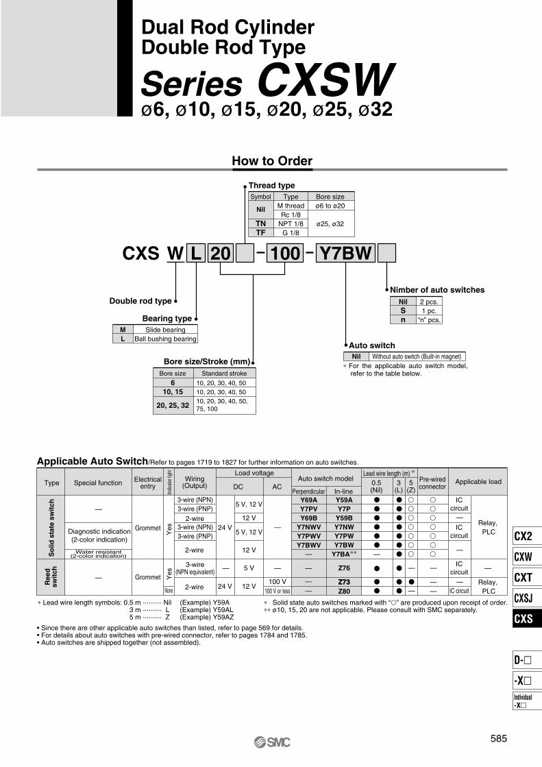
L
Nil
S
n
2 pcs.1 pc.
“n” pcs.
10020
Bearing type
Slide bearingBall bushing bearing
CXS W
Double rod type
M
L
Nimber of auto switches
Bore size/Stroke (mm)
Bore size
10, 20, 30, 40, 5010, 20, 30, 40, 5010, 20, 30, 40, 50, 75, 100
6
10, 15
20, 25, 32
Auto switch
Nil Without auto switch (Built-in magnet)
Standard stroke
Y7BW
Applicable Auto Switch/Refer to pages 1719 to 1827 for further information on auto switches.
How to Order
∗ For the applicable auto switch model, refer to the table below.
Thread type
Bore sizeø6 to ø20
ø25, ø32
TypeM threadRc 1/8
NPT 1/8G 1/8
Symbol
Nil
TN
TF
ACDC
Lead wire length (m) ∗
5 V
5 V, 12 V
12 V
5 V, 12 V
12 V
24 V
Z76
Z73
Y59A
Y7P
Y59B
Y7NW
Y7PW
Y7BW
Y7BA∗∗
Y69A
Y7PV
Y69B
Y7NWV
Y7PWV
Y7BWV
100 V24 V 12 V
Z73
Z80100 V or less
Load voltageWiring
(Output)Pre-wiredconnector
Applicable loadSpecial functionType Electricalentry
Indi
cato
r lig
htY
esY
es
Grommet
Grommet
Reed
sw
itch
So
lid
sta
te s
wit
ch
Water resistant(2-color indication)
Diagnostic indication(2-color indication)
—
—
None
3-wire (NPN)3-wire (PNP)
2-wire3-wire (NPN)3-wire (PNP)
2-wire
2-wire
3-wire(NPN equivalent) — —
—
—
——
—
—
—
—
—
——
ICcircuit
ICcircuit
ICcircuit
IC circuit
—
—
—
—
Relay, PLC
Relay, PLC
0.5(Nil)
3 (L)
5 (Z)
Auto switch model
Perpendicular In-line
• Since there are other applicable auto switches than listed, refer to page 569 for details.• For details about auto switches with pre-wired connector, refer to pages 1784 and 1785.• Auto switches are shipped together (not assembled).
∗ Solid state auto switches marked with “�” are produced upon receipt of order.∗∗ ø10, 15, 20 are not applicable. Please consult with SMC separately.
∗ Lead wire length symbols: 0.5 m ·········· Nil (Example) Y59A3 m ·········· L (Example) Y59AL5 m ·········· Z (Example) Y59AZ
Dual Rod CylinderDouble Rod Type
ø6, ø10, ø15, ø20, ø25, ø32Series CXSW
585
CX2
CXW
CXT
CXSJ
CXS
Individual-X�
D-�
-X�
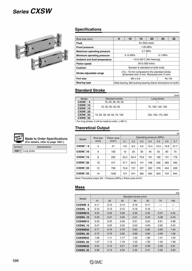
Specifications
Bore size (mm)
Fluid
Proof pressure
Maximum operating pressure
Minimum operating pressure
Ambient and fluid temperature
Piston speed
Cushion
Stroke adjustable range
Port size
Bearing type
6 10 15
Air (Non-lube)
1.05 MPa
0.7 MPa
–10 to 60°C (No freezing)
50 to 500 mm/s
Bumper is standard on both ends
0 to –10 mm compared to the standard stroke(Extended end: 5 mm, Retracted end: 5 mm)
Slide bearing, Ball bushing bearing (Same dimensions for both)
0.15 MPa 0.1 MPa
20 25 32
Note) Theoretical output (N) = Pressure (MPa) x Piston area (mm2)
∗ For long strokes, it will be made-to-order. (–XB11)
(N)
(kg)
Model
CXSW� 6
CXSW�10
CXSW�15
CXSW�20
CXSW�25
CXSW�32
Rod size(mm)
4
6
8
10
12
16
4.6
10
25.2
47.1
75.6
121
6.2
20
50.4
94.2
151
241
9.3
30
75.6
141
227
362
12.4
40
101
188
302
482
15.5
50
126
236
378
603
18.6
60
151
283
454
724
21.7
70
176
330
529
844
0.1 0.2 0.3 0.4
Operating pressure (MPa)
0.5 0.6 0.7
Model10
0.11
0.12
0.24
0.25
0.43
0.47
0.71
0.75
1.06
1.07
2.04
2.06
20
0.13
0.13
0.26
0.27
0.45
0.50
0.74
0.79
1.11
1.12
2.12
2.15
30
0.14
0.15
0.28
0.29
0.48
0.52
0.78
0.82
1.17
1.18
2.21
2.23
40
0.16
0.16
0.30
0.31
0.51
0.55
0.82
0.86
1.22
1.23
2.29
2.32
50
0.17
0.18
0.32
0.33
0.54
0.58
0.85
0.90
1.28
1.29
2.38
2.41
75
—
—
0.37
0.38
0.61
0.65
0.95
0.99
1.41
1.42
2.59
2.62
100
—
—
0.42
0.43
0.68
0.42
1.04
1.08
1.55
1.56
2.81
2.83
Standard stroke (mm)
CXSWM
CXSWL
CXSWM
CXSWL
CXSWM
CXSWL
CXSWM
CXSWL
CXSWM
CXSWL
CXSWM
CXSWL
6
6
10
10
15
15
20
20
25
25
32
32
Piston area(mm2)
31
100
252
471
756
1206
M5 x 0.8 Rc 1/8
Standard Stroke
CXSW� 6CXSW�10
CXSW�15
CXSW�20
CXSW�25
CXWS�32
Model Standard stroke10, 20, 30, 40, 50
(mm)
Theoretical Output
Mass
10, 20, 30, 40, 50, 75, 100
10, 20, 30, 40, 50
Long stroke—
125, 150, 175, 200
75, 100, 125, 150
–XB11 Long stroke
Symbol Specifications
Made to Order Specifications(For details, refer to page 1861.)
586
Series CXSW
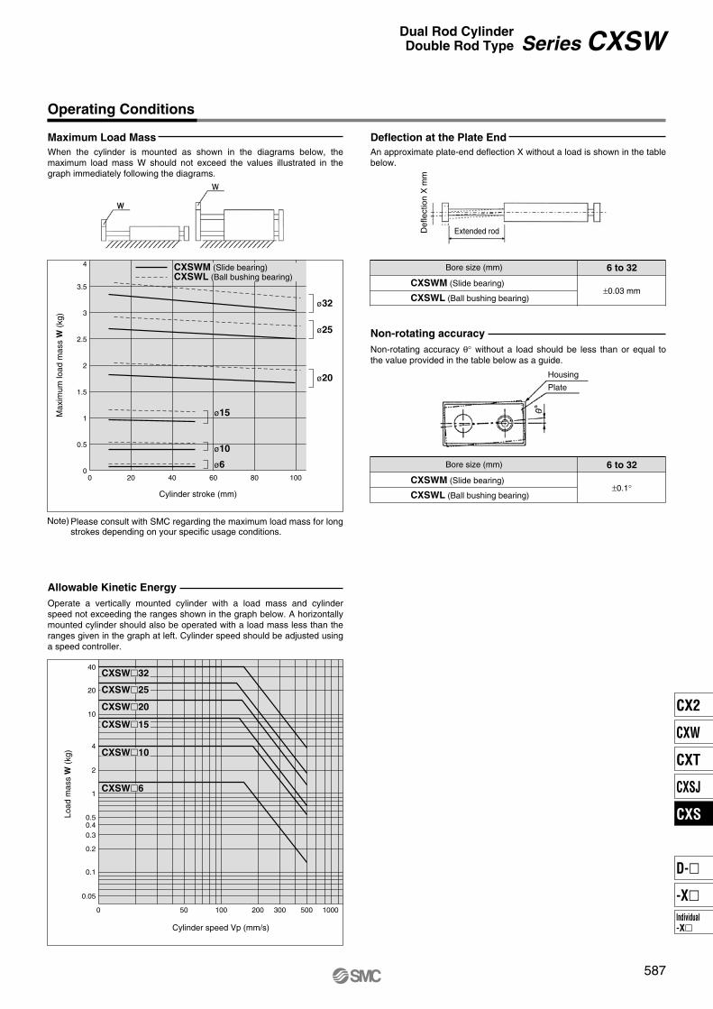
Maximum Load Mass Deflection at the Plate End
Non-rotating accuracy
Allowable Kinetic Energy
Bore size (mm) 6 to 32
±0.03 mmCXSWM (Slide bearing)
CXSWL (Ball bushing bearing)
Bore size (mm) 6 to 32
±0.1°CXSWM (Slide bearing)
CXSWL (Ball bushing bearing)
4
3.5
3
2.5
2
1.5
1
0.5
00 20 40 60 80 100
Cylinder stroke (mm)
Max
imum
load
mas
s W
(kg
)
ø32
ø25
ø20
CXSWM (Slide bearing)CXSWL (Ball bushing bearing)
ø15
ø10
ø6
40
20
10
4
2
1
0.50.40.3
0.2
0.1
0.05
0 50
Cylinder speed Vp (mm/s)
Load
mas
s W
(kg
)
100 200 300 500 1000
CXSW�32
CXSW�25
CXSW�20
CXSW�15
CXSW�10
CXSW�6
Operating Conditions
When the cylinder is mounted as shown in the diagrams below, the maximum load mass W should not exceed the values illustrated in the graph immediately following the diagrams.
Operate a vertically mounted cylinder with a load mass and cylinder speed not exceeding the ranges shown in the graph below. A horizontally mounted cylinder should also be operated with a load mass less than the ranges given in the graph at left. Cylinder speed should be adjusted using a speed controller.
An approximate plate-end deflection X without a load is shown in the table below.
Non-rotating accuracy θ° without a load should be less than or equal to the value provided in the table below as a guide.
Def
lect
ion
X m
m
Extended rod
Housing
Plate
Please consult with SMC regarding the maximum load mass for long strokes depending on your specific usage conditions.
Note)
587
Series CXSWDual Rod CylinderDouble Rod Type
CX2
CXW
CXT
CXSJ
CXS
Individual-X�
D-�
-X�

r u iy w !7!8!2 !3@0@3@2@1
q et!1 o !0 !8
r u iy w!3@2@0@3@1 !7!4!5!2
q!8!0!1 ot e
Construction
CXSWM (Slide bearing)
CXSWL (Ball bushing bearing)
CXSW�6 CXSW�10
CXSWM6
CXSWL6
CXSWL10, 15
CXSW�25, 32
(Piston part)
w y @3 i @3 y y i
r !5 !6
!9 r !5 !6
!9 r
@3 yi e
No.1
2
3
4
5
6
7
8
9
10
Description Materialluminum alloyCarbon steelCarbon steel
Aluminum bearing alloyAluminum alloyAluminum alloyAluminum alloy
—Carbon steelCarbon steel
Noteard anodized
Hard chrome platedHard chrome plated
Hard anodizedChromatedChromated
Nickel platedNickel plated
Housing
Piston rod A
Piston rod B
Rod cover
Plate
Piston A
Piston B
Magnet
Bumper bolt
Hexagon nut
Component Parts
Note) Piston rod for CXSL is quenched.
No.13
14
15
16
17
18
19
20
21
22
23
Description MaterialSpecial steel
Synthetic resin—
Synthetic resinPolyurethane
Chromium steelAluminum alloy
NBRNBRNBRNBR
NoteNickel plated
Nickel plated
Retaining ring
Bumper holder
Ball bushing
Bearing spacer
Bumper
Plug
Seal retainer
Piston seal
Rod seal
O-ring
O-ring
Component Parts
Replacement Parts/Seal Kit
Bore size (mm) Kit no. Contents
Set of nos. above@0, @1 and @2
CXSWM6-PSCXSWL6-PSCXSWM10-PSCXSWL10APSCXSWM15-PSCXSWL15APSCXSWM20-PSCXSWL20APSCXSWM25-PSCXSWL25APSCXSWM32-PSCXSWL32APS
6
10
15
20
25
32
Hexagon socket headcap screw
Hexagon socket headset screw
Chromium steel
Chromium steel
Nickel plated
Nickel plated
11
12∗ For CXSWL6, aluminum bearing alloy is used for !6.
∗ Seal kit includes @0 to @2. To order them, use the order number given in the left table.
∗ Since the seal kit does not include a grease pack, order it separately. Grease pack part no.: GR-S-010 (10 g)
∗
∗
∗
588
Series CXSW
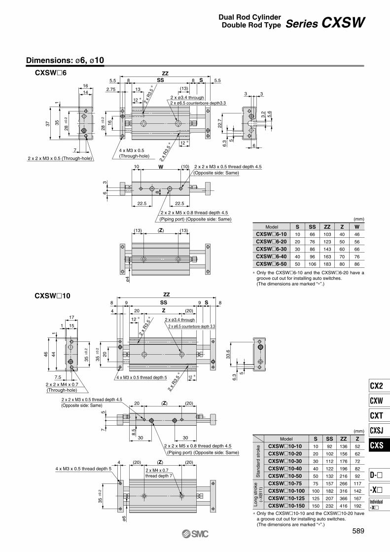
12 ∗
12 ∗33
6
(13)(Z)
(10)W
22.5
(13)
ZZ
5.5S8
5.6
3.2
6
22.7
8
7
1416
2.75
5.5
3
22.5
1
28±0
.2
±0.2
16
5
6.3
(13)
ø4
10
28
37 35
SS
13
8
2 x ø6.5 counterbore depth3.32 x ø3.4 through
(Opposite side: Same)
(Piping port) (Opposite side: Same)
2 x
R3.
5 ∗
2 x
R3.
5 ∗
4 x M3 x 0.5 (Through-hole)2 x 2 x M3 x 0.5 (Through-hole)
2 x 2 x M3 x 0.5 thread depth 4.5
2 x 2 x M5 x 0.8 thread depth 4.5
35
20
(20)
8.5
35
7.5
46 44 33.6
6.3 5
75
ZZ
8S
ø6
998
4
1
1
15
17
(Z)(20)4
35
20
30
(20)
30
(Z)
2 x
R3.
5 ∗
20 (20)
12 ∗
12 ∗
2 x
R3.
5 ∗
SS
Z
4 x M3 x 0.5 thread depth 5
(Piping port) (Opposite side: Same)
thread depth 72 x M4 x 0.7
(Through-hole)
(Opposite side: Same)
2 x ø6.5 counterbore depth 3.3
2 x ø3.4 through
2 x 2 x M4 x 0.7
4 x M3 x 0.5 thread depth 5
2 x 2 x M3 x 0.5 thread depth 4.5
2 x 2 x M5 x 0.8 thread depth 4.5
±0.2
±0.2
±0.2
Model
CXSW�6-10
CXSW�6-20
CXSW�6-30
CXSW�6-40
CXSW�6-50
WZZZSSS
10
20
30
40
50
40
50
60
70
80
46
56
66
76
86
103
123
143
163
183
66
76
86
96
106
(mm)
Model
CXSW�10-10
CXSW�10-20
CXSW�10-30
CXSW�10-40
CXSW�10-50
CXSW�10-75
CXSW�10-100
CXSW�10-125
CXSW�10-150
ZZZSSS
10
20
30
40
50
75
100
125
150
52
62
72
82
92
117
142
167
192
136
156
176
196
216
266
316
366
416
92
102
112
122
132
157
182
207
232
(mm)
Dimensions: ø6, ø10
CXSW�6
CXSW�10
∗ Only the CXSW�10-10 and the CXSW�10-20 have a groove cut out for installing auto switches.(The dimensions are marked “∗”.)
Sta
ndar
d st
roke
Long
str
oke
(–X
B11
)
∗ Only the CXSW�6-10 and the CXSW�6-20 have a groove cut out for installing auto switches.(The dimensions are marked “∗”.)
589
Series CXSWDual Rod CylinderDouble Rod Type
CX2
CXW
CXT
CXSJ
CXS
Individual-X�
D-�
-X�
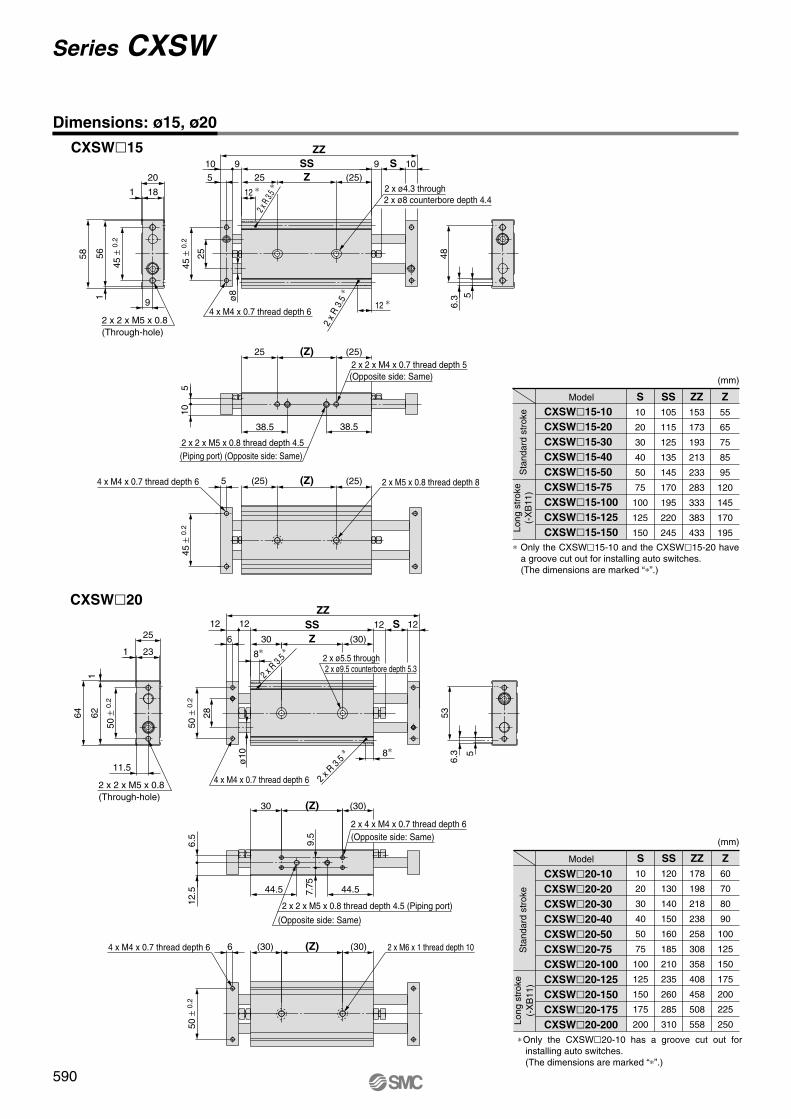
(Z)
(Z)
Z
S
ZZ
SS
Z
(Z)
(Z)
ZZ
SSS
2 x M6 x 1 thread depth 10
ZZZSSS
10
20
30
40
50
75
100
125
150
55
65
75
85
95
120
145
170
195
153
173
193
213
233
283
333
383
433
105
115
125
135
145
170
195
220
245
ZZZSSS
10
20
30
40
50
75
100
125
150
175
200
60
70
80
90
100
125
150
175
200
225
250
178
198
218
238
258
308
358
408
458
508
558
120
130
140
150
160
185
210
235
260
285
310
CXSW�15
CXSW�20
590
Series CXSW
Dimensions: ø15, ø20
6.3
48
5
9 10
(25)
38.5
(25)
(25)
(25)5
25
1
1
20
18
9
58 56
5
10 9
255
10
38.5
25
45 ±
0.2
45 ±
0.2
ø8
2 x 2 x M5 x 0.8 (Through-hole)
12 ∗
12 ∗
2 x R
3.5 ∗
2 x
R 3.
5 ∗
4 x M4 x 0.7 thread depth 6
2 x ø4.3 through2 x ø8 counterbore depth 4.4
2 x 2 x M4 x 0.7 thread depth 5(Opposite side: Same)
2 x 2 x M5 x 0.8 thread depth 4.5(Piping port) (Opposite side: Same)
4 x M4 x 0.7 thread depth 6
45 ±
0.2
2 x M5 x 0.8 thread depth 8
1212
(30)
536.
3 5
30
12 12
6
ø10
28
(30)
2 x R
3.5 ∗
2 x R 3.
5 ∗8∗
8∗
2 x ø9.5 counterbore depth 5.32 x ø5.5 through
4 x M4 x 0.7 thread depth 6
50 ±
0.2
50 ±
0.2
11.5
64 621
25
1 23
2 x 2 x M5 x 0.8 (Through-hole)
(30)
44.5
(30)6
12.5
6.5
44.5 7.75
9.5
30
2 x 4 x M4 x 0.7 thread depth 6(Opposite side: Same)
2 x 2 x M5 x 0.8 thread depth 4.5 (Piping port)
(Opposite side: Same)
4 x M4 x 0.7 thread depth 6
50 ±
0.2
Model
CXSW�15-10
CXSW�15-20
CXSW�15-30
CXSW�15-40
CXSW�15-50
CXSW�15-75
CXSW�15-100
CXSW�15-125
CXSW�15-150
(mm)
Sta
ndar
d st
roke
Long
str
oke
(-X
B11
)
∗ Only the CXSW�15-10 and the CXSW�15-20 have a groove cut out for installing auto switches.(The dimensions are marked “∗”.)
Model
CXSW�20-10
CXSW�20-20
CXSW�20-30
CXSW�20-40
CXSW�20-50
CXSW�20-75
CXSW�20-100
CXSW�20-125
CXSW�20-150
CXSW�20-175
CXSW�20-200
(mm)
Sta
ndar
d st
roke
Long
str
oke
(-X
B11
)
∗ Only the CXSW�20-10 has a groove cut out for installing auto switches.(The dimensions are marked “∗”.)

(Z)
(Z)
S
Z
ZZ
SS
2 x M8 x 1.25 thread depth 12
(Z)
(Z)
SSS
ZZ
Z
ZZZSSS
10
20
30
40
50
75
100
125
150
175
200
62
72
82
92
102
127
152
177
202
227
252
180
200
220
240
260
310
360
410
460
510
560
122
132
142
152
162
187
212
237
262
287
312
ZZZSSS
10
20
30
40
50
75
100
125
150
175
200
83
93
103
113
123
148
173
198
223
248
273
213
233
253
273
293
343
393
443
493
543
593
143
153
163
173
183
208
233
258
283
308
333
CXSW�25
CXSW�32
591
Dimensions: ø25, ø32
646.
3 5
1212
(30)30
14
301 28
80
178
ø12
6
12 12
60 ±
0.2
60 ±
0.2
2 x 2 x M6 x 1 (Through-hole)4 x M5 x 0.8 thread depth 7.5
8 ∗
2 x R
3.5∗
2 x ø6.9 through2 x ø11 counterbore depth 6.3
35
2 x R
3.5∗ 8 ∗
46
(30)
(30)30
6 (30)
915
8.5
13
46
2 x 2 x Rc 1/8 thread depth 6.5
(Piping port) (Opposite side: Same)
60 ±
0.2
2 x 4 x M5 x 0.8 thread depth 7.5 (Opposite side: Same)
8 ∗
75 ±
0.2
2 x R
3.5∗
2 x R
3.5∗ 8 ∗
75 ±
0.2
96
36
38
1
18
198
(30)
1614
(30)8
ø16
44
1416
8 30
30
2 x 2 x M6 x 1 (Through-hole)
4 x M5 x 0.8 thread depth 7.5
4 x M5 x 0.8 thread depth 8
2 x ø6.9 through
2 x ø11 counterbore depth 6.3
766.
35
56
11.5
19
209
56
2 x 4 x M5 x 0.8 thread depth 7.5(Opposite side: Same)
(Opposite side: Same)2 x 2 x Rc 1/8 thread depth 6.5 (Piping port)
(30)(30) 2 x M8 x 1.25 thread depth 128
75 ±
0.2
4 x M5 x 0.8 thread depth 8
Series CXSWDual Rod CylinderDouble Rod Type
Model
CXSW�25-10
CXSW�25-20
CXSW�25-30
CXSW�25-40
CXSW�25-50
CXSW�25-75
CXSW�25-100
CXSW�25-125
CXSW�25-150
CXSW�25-175
CXSW�25-200
(mm)
Sta
ndar
d st
roke
Long
str
oke
(-X
B11
)
∗ Only the CXSW�25-10 has a groove cut out for installing auto switches.(The dimensions are marked “∗”.)
∗ Only the CXSW�32-10 has a groove cut out for installing auto switches.(The dimensions are marked “∗”.)
Model
CXSW�32-10
CXSW�32-20
CXSW�32-30
CXSW�32-40
CXSW�32-50
CXSW�32-75
CXSW�32-100
CXSW�32-125
CXSW�32-150
CXSW�32-175
CXSW�32-200
(mm)
Sta
ndar
d st
roke
Long
str
oke
(-X
B11
)
CX2
CXW
CXT
CXSJ
CXS
Individual-X�
D-�
-X�
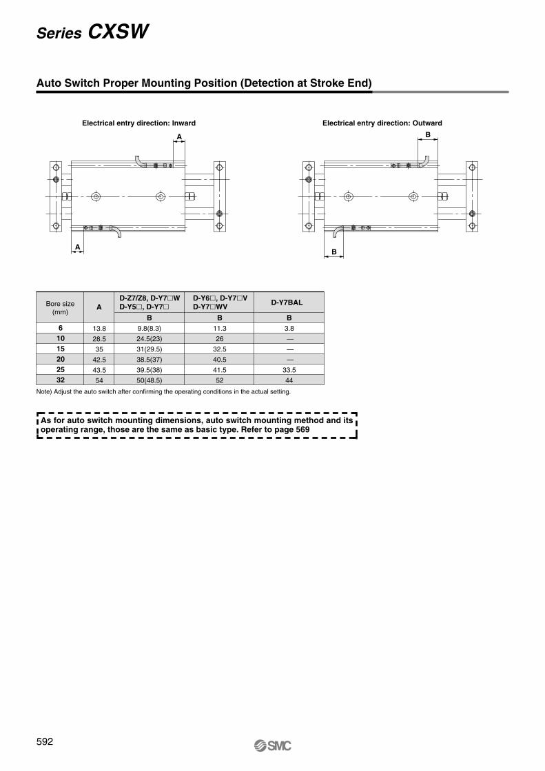
6
10
15
20
25
32
A
B
9.8(8.3)
24.5(23)
31(29.5)
38.5(37)
39.5(38)
50(48.5)
13.8
28.5
35
42.5
43.5
54
B
11.3
26
32.5
40.5
41.5
52
B
3.8
—
—
—
33.5
44
A
A B
B
Note) Adjust the auto switch after confirming the operating conditions in the actual setting.
As for auto switch mounting dimensions, auto switch mounting method and its operating range, those are the same as basic type. Refer to page 569
592
Series CXSW
Auto Switch Proper Mounting Position (Detection at Stroke End)
Electrical entry direction: Inward Electrical entry direction: Outward
D-Z7/Z8, D-Y7�W
D-Y5�, D-Y7�D-Y6�, D-Y7�V
D-Y7�WVD-Y7BALBore size
(mm)
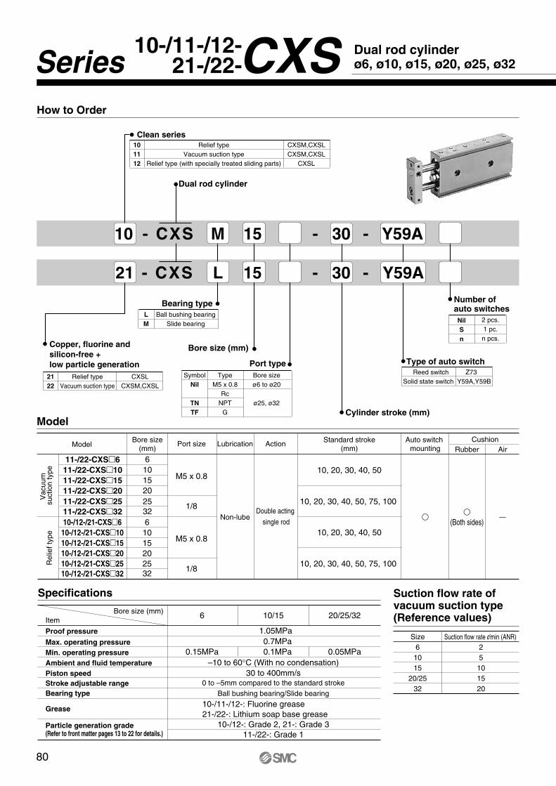
SymbolNil
TN
TF
Port type
TypeM5 x 0.8
RcNPT
G
Bore sizeø6 to ø20
ø25, ø32
10 - CXS M 15 - 30 - Y59A
Dual rod cylinder
Model
11-/22-CXS�10
11-/22-CXS�15
11-/22-CXS�20
11-/22-CXS�25
11-/22-CXS�32
Vac
uum
su
ctio
n ty
peR
elie
f typ
e
Bore size(mm)
1015202532
10-/12-/21-CXS�10
10-/12-/21-CXS�15
10-/12-/21-CXS�20
10-/12-/21-CXS�25
10-/12-/21-CXS�32
1015202532
Port size
1/8
M5 x 0.8
1/8
M5 x 0.8
Lubrication ActionCushion
Rubber Air
Non-lubeDouble acting
single rod
Standard stroke(mm)
10, 20, 30, 40, 50
Auto switch mounting
��
(Both sides)—
10, 20, 30, 40, 50, 75, 100
10, 20, 30, 40, 50
10, 20, 30, 40, 50, 75, 100
11-/22-CXS�6 6
10-/12-/21-CXS�6 6
Model
How to Order
21 - CXS L 15 - 30 - Y59A
10-/11-/12-21-/22-
0 to –5mm compared to the standard strokeBall bushing bearing/Slide bearing
10/15 20/25/326
0.1MPa 0.05MPa0.15MPa
1.05MPa0.7MPa
–10 to 60°C (With no condensation)
Bore size (mm)
Specifications
30 to 400mm/s
10-/11-/12-: Fluorine grease21-/22-: Lithium soap base grease
10-/12-: Grade 2, 21-: Grade 311-/22-: Grade 1
25101520
Size Suction flow rate l/min (ANR) 61015
20/2532
Suction flow rate of vacuum suction type(Reference values)
L
M
Bearing type
Ball bushing bearingSlide bearing Nil
S
n
Number of auto switches
2 pcs.1 pc.n pcs.
Reed switch
Type of auto switch
Z73Solid state switch Y59A,Y59B
Cylinder stroke (mm)
Bore size (mm)
10
11
12
Relief typeVacuum suction type
Relief type (with specially treated sliding parts)
CXSM,CXSLCXSM,CXSL
CXSL
Clean series
21
22
Relief typeVacuum suction type
CXSLCXSM,CXSL
Copper, fluorine and
silicon-free +
low particle generation
80
Proof pressure
Max. operating pressure
Min. operating pressure
Ambient and fluid temperature
Piston speed
Stroke adjustable range
Item
Bearing type
Grease
Particle generation grade (Refer to front matter pages 13 to 22 for details.)
Dual rod cylinderø6, ø10, ø15, ø20, ø25, ø32Series CXS

Auto switches / Proper mounting position for stroke end detection
Auto switch specifications (Refer to Best Pneumatics catalog for detailed specifications and auto switches not in the following table.)
StyleReed switch
2-wire type3-wire type
Solid state switch
Auto switch part no.
Electrical entry direction: Inward Electrical entry direction: Outward
D-Z73
D-Y59B
D-Y59A
Load voltage
24 VDC,100 VAC24 VDC (10 to 28V)
28 VDC or less
5 to 40mA, 5 to 20mA 5 to 40mA
40mA or less
Load current range Indicator light�
�
�
ApplicationRelay, PLC
24 VDC Relay, PLCIC circuit, Relay, PLC
PLC: Programmable Logic Controller
C
D
A
B
Dual rod cylinder CXSL12-21-CXS �/10-/11-
22-
Refer to applicable auto switch list — Page 182.
Note 1) The above mentioned values are indicated as a guide for auto switch mounting position for stroke end detection. When actually mounting an auto switch, adjust the position after confirming the operating state of the auto switch.
Note 2) Lead wire entry is inward when the product is shipped.
Bore size
10152025
D-Z73 D-Y59A,D-Y59BA B
C D
6 20.5273850
50.560
4.58
4.57
8.59
1521.532.544.545
54.5
-12.5-11.53.53.532
C
16.5233446
46.556
D
0.54
0.5355
(mm)
81
Air
cylin
der
Rot
ary
actu
ator
Air
grip
per
Dire
ctio
nal c
ontr
olva
lve
Fitt
ings
& T
ubin
gP
ress
ure
switc
hC
lean
gas
filte
rF
low
con
trol
equi
pmen
tF
ilter
, Pre
ssur
eco
ntro
l equ
ipm
ent
Air
prep
arat
ion
equi
pmen
t
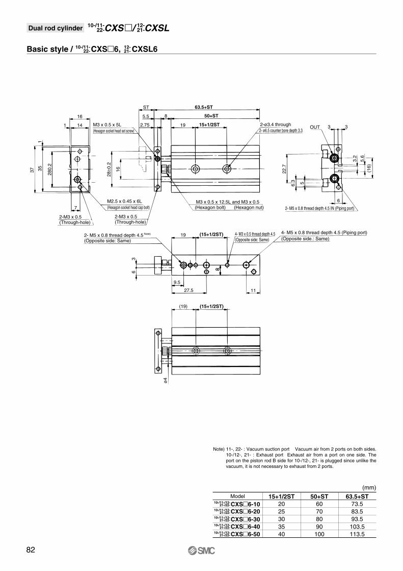
Basic style / CXS�6, CXSL6
(mm)Model
CXS�6-1021-/22-10-/11-/12-
21-/22-10-/11-/12-
21-/22-10-/11-/12-
21-/22-10-/11-/12-
21-/22-10-/11-/12-
CXS�6-20
CXS�6-30
CXS�6-40
CXS�6-50
15+1/2ST
2025303540
50+ST
60708090
100
63.5+ST
73.583.593.5103.5113.5
35 16 22.7
3.2
5.6
(16)
6.3 5
1
37
63.5+ST
50+ST
15+1/2ST
16
ST
8
2.75
5.5
19
63
2-ø3.4 through
M3 x 0.5 x 12.5L and M3 x 0.52- M5 x 0.8 thread depth 4.5 IN (Piping port)
OUT 33
6
4- M5 x 0.8 thread depth 4.5 (Piping port)(Opposite side.: Same)
2- M5 x 0.8 thread depth 4.5 Note)
(Opposite side: Same)
2-M3 x 0.5(Through-hole)
M2.5 x 0.45 x 6L(Hexagon socket head cap bolt)
M3 x 0.5 x 5L(Hexagon socket head set screw)
4- M3 x 0.5 thread depth 4.5(Opposite side: Same)
2-M3 x 0.5(Through-hole)
2- ø6.5 counter bore depth 3.3141
7
(19) (15+1/2ST)
19
27.5 11
9.5
(15+1/2ST)
280.
2
28±0
.2
ø4
(Hexagon bolt) (Hexagon nut)
82
Note) 11-, 22- : Vacuum suction port Vacuum air from 2 ports on both sides. 10-/12-, 21- : Exhaust port Exhaust air from a port on one side. The port on the piston rod B side for 10-/12-, 21- is plugged since unlike the vacuum, it is not necessary to exhaust from 2 ports.
Dual rod cylinder CXSL12-21-CXS �/10-/11-
22-
10-/11-22-
12-21-

Basic style / CXS�10, CXSL10
(mm)Model
CXS�10-10
S SS ZZ Z
10 70 87 3020 80 97 3030 90 107 4040 100 117 4050 110 127 40
CXS�10-20
CXS�10-30
CXS�10-40
CXS�10-50
44 20 33.6
6.3 5
1
46
ZZ
SS17
S
8 9
4 201 Z
8.57
5
2-ø3.4 through
M4 x 0.7 x 14.5L and M4 x 0.7
4- M5 x 0.8 thread depth 4.5 (Piping port)(Opposite side: Same)
2- M5 x 0.8 thread depth 4.5 Note)
(Opposite side: Same)
2-M4 x 0.7(Through-hole)
M3 x 0.5 x 10L(Hexagon socket head cap bolt)
M5 x 0.8 x 5L(Hexagon socket head set screw)
4- M3 x 0.5 thread depth 4.5(Opposite side: Same)
2-M3 x 0.5thread depth 5
2- M3 x 0.5 thread depth 52-M4 x 0.7thread depth 7
2- ø6.5 counter bore depth 3.315
7.5
4 (20) (Z)
20
35 8
8
(Z)
35±0
.2
35±0
.235
±0.2
ø6
(Hexagon bolt) (Hexagon nut)
Note) 11-, 22- : Vacuum suction port Vacuum air from 2 ports on both sides.10-/12-, 21- : Exhaust port Exhaust air from a port on one side. The port on the piston rod B side for 10-/12-, 21- is plugged since unlike the vacuum, it is not necessary to exhaust from 2 ports.
21-/22-10-/11-/12-
21-/22-10-/11-/12-
21-/22-10-/11-/12-
21-/22-10-/11-/12-
21-/22-10-/11-/12-
Dual rod cylinder CXSL12-21-CXS �/10-/11-
22-
10-/11-22-
12-21-
83
Air
cylin
der
Rot
ary
actu
ator
Air
grip
per
Dire
ctio
nal c
ontr
olva
lve
Fitt
ings
& T
ubin
gP
ress
ure
switc
hC
lean
gas
filte
rF
low
con
trol
equi
pmen
tF
ilter
, Pre
ssur
eco
ntro
l equ
ipm
ent
Air
prep
arat
ion
equi
pmen
t
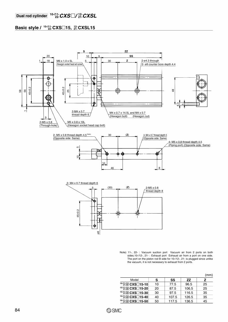
Basic style / CXS�15, CXSL15
(mm)Model
CXS�15-10
S SS ZZ Z
10 77.5 96.5 2520 87.5 106.5 2530 97.5 116.5 3540 107.5 126.5 3550 117.5 136.5 45
21-/22-10-/11-/12-
21-/22-10-/11-/12-
21-/22-10-/11-/12-
21-/22-10-/11-/12-
21-/22-10-/11-/12-
CXS�15-20
CXS�15-30
CXS�15-40
CXS�15-50
56 25 48
6.3 5
1
58
ZZ
SS20
S
10 9
5 301
9
Z
ø8
510
2-ø4.3 through
M4 x 0.7 x 14.5L and M4 x 0.7
4- M5 x 0.8 thread depth 4.5(Piping port) (Opposite side: Same)
2- M5 x 0.8 thread depth 4.5 Note)
(Opposite side: Same)
M6 x 1.0 x 5L(Hexagon socket head set screw)
M5 x 0.8 x 10L(Hexagon socket head cap bolt)
2-M4 x 0.7thread depth 6
4- M4 x 0.7 thread depth 5(Opposite side: Same)
2-M5 x 0.8(Through-hole)
2- M4 x 0.7 thread depth 6
2-M5 x 0.8thread depth 8
2- ø8 counter bore depth 4.418
(30) (Z)
30
10
846
5
(Z)
(Hexagon bolt) (Hexagon nut)
45±0
.2
45±0
.2
45±0
.2
Note) 11-, 22- : Vacuum suction port Vacuum air from 2 ports on both sides.10-/12-, 21- : Exhaust port Exhaust air from a port on one side. The port on the piston rod B side for 10-/12-, 21- is plugged since unlike the vacuum, it is not necessary to exhaust from 2 ports.
10-/11-22-
12-21-
Dual rod cylinder CXSL12-21-CXS �/10-/11-
22-
84
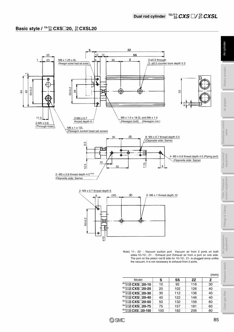
Basic style / CXS�20, CXSL20
(mm)Model
CXS�20-10
S SS ZZ Z
10 92 116 3020 102 126 4030 112 136 4040 122 146 4050 132 156 60
CXS�20-20
CXS�20-30
CXS�20-40
CXS�20-50
75 157 181 60100 182 206 80
CXS�20-75
CXS�20-100
62 28 53
6.3 5
1
64
ZZ
SS25
S
12 12
6 301
11.5
Z
ø10
6.5
12.5
7.75
9.5
2-ø5.5 through
M6 x 1.0 x 18.5L and M6 x 1.0
8- M4 x 0.7 thread depth 5.5(Opposite side: Same)
M8 x 1.25 x 6L(Hexagon socket head set screw)
M6 x 1 x 12L(Hexagon socket head set screw)
4- M5 x 0.8 thread depth 4.5 (Piping port) (Opposite side: Same)
2-M5 x 0.8(Through-hole)
2-M4 x 0.7thread depth 6
2- M5 x 0.8 thread depth 4.5 Note)
(Opposite side: Same)
2- M4 x 0.7 thread depth 6
2- M6 x 1 thread depth 10
2- ø9.5 counter bore depth 5.323
6 (30) (Z)
30
8
10
52
(Z)
(Hexagon bolt) (Hexagon nut.)
50±0
.2
50±0
.2
50±0
.2
Note) 11-, 22- : Vacuum suction port Vacuum air from 2 ports on both sides.10-/12-, 21- : Exhaust port Exhaust air from a port on one side. The port on the piston rod B side for 10-/12-, 21- is plugged since unlike the vacuum, it is not necessary to exhaust from 2 ports.
21-/22-10-/11-/12-
21-/22-10-/11-/12-
21-/22-10-/11-/12-
21-/22-10-/11-/12-
21-/22-10-/11-/12-
21-/22-10-/11-/12-
21-/22-10-/11-/12-
Dual rod cylinder CXSL12-21-CXS �/10-/11-
22-
10-/11-22-
12-21-
85
Air
cylin
der
Rot
ary
actu
ator
Air
grip
per
Dire
ctio
nal c
ontr
olva
lve
Fitt
ings
& T
ubin
gP
ress
ure
switc
hC
lean
gas
filte
rF
low
con
trol
equi
pmen
tF
ilter
, Pre
ssur
eco
ntro
l equ
ipm
ent
Air
prep
arat
ion
equi
pmen
t
Basic style / CXS�25, CXSL25
(mm)Model
CXS�25-10
S SS ZZ Z
10 94 118 3020 104 128 4030 114 138 4040 124 148 4050 134 158 60
CXS�25-20
CXS�25-30
CXS�25-40
CXS�25-50
75 159 183 60100 184 208 80
CXS�25-75
CXS�25-100
78 64
6.3 5
80
1
ZZ
SS30
S
12 12
6 301
14
Z
ø12
9
3 5
15
8.5
13
2-ø6.9 through
M6 x 1 x 18.5L and M6 x 1
8- M5 x 0.8 thread depth 7.5(Opposite side: Same)
2-M6 x 1 (Through-hole)
M8 x 1.25 x 6L(Hexagon socket head set screw)
4- (Rc, NPT, G) 1/8 thread depth 6.5 (Piping port), (Opposite side: Same)
2-M5 x 0.8Thread depth 7.5
2- M5 x 0.8 thread depth 4.5 Note)
(Opposite side: Same)
2-M5 x 0.8thread depth 7.5
M6 x 1 x 14L (Hexagon socket head cap bolt)
2- M8 x 1.25 thread depth 12
2-ø11 counter bore depth 6.328
6 (30) (Z)
30
10 9
53.5
(Z)
(Hexagon bolt) (Hexagon nut)
60±0
.2
60±0
.2
60±0
.2
Note) 11-, 22- : Vacuum suction port Vacuum air from 2 ports on both sides.10-/12-, 21- : Exhaust port Exhaust air from a port on one side. The port on the piston rod B side for 10-/12-, 21- is plugged since unlike the vacuum, it is not necessary to exhaust from 2 ports.
21-/22-10-/11-/12-
21-/22-10-/11-/12-
21-/22-10-/11-/12-
21-/22-10-/11-/12-
21-/22-10-/11-/12-
21-/22-10-/11-/12-
21-/22-10-/11-/12-
Dual rod cylinder CXSL12-21-CXS �/10-/11-
22-
10-/11-22-
12-21-
86

Basic style / CXS�32, CXSL32
(mm)Model
CXS�32-10
S SS ZZ Z
10 104 134 4020 114 144 5030 124 154 5040 134 164 5050 144 174 60
CXS�32-20
CXS�32-30
CXS�32-40
CXS�32-50
75 169 199 70100 194 224 90
CXS�32-75
CXS�32-100
96 44
ø16
76
6.3 5
1
98
ZZ
SS38
S
16 14
8 301
18
Z
11.5
19 920
2-ø6.9 through
M8 x 1.25 x 23L and M8 x 1.25
8- M5 x 0.8 thread depth 7.5(Opposite side: Same)
2- M5 x 0.8 thread depth 4.5 Note)
(Opposite side: Same)
2-M6 x 1 (Through-hole) 2-M5 x 0.8thread depth 8
M10 x 1.5 x 8L(Hexagon socket head cap bolt)
4- (Rc, NPT, G) 1/8 thread depth 6.5(Piping port), (Opposite side: Same)
2- M5 x 0.8 thread depth 8
M8 x 1.25 x 16L(Hexagon socket head cap bolt)
2-M8 x 1.25thread depth 12
2-ø11 counter bore depth 6.336
8 (30) (Z)
30
13
1063.5
(Z)
(Hexagon bolt) (Hexagon nut)
75±0
.2
75±0
.2
75±0
.2
Note) 11-, 22- : Vacuum suction port Vacuum air from 2 ports on both sides.10-/12-, 21- : Exhaust port Exhaust air from a port on one side. The port on the piston rod B side for 10-/12-, 21- is plugged since unlike the vacuum, it is not necessary to exhaust from 2 ports.
21-/22-10-/11-/12-
21-/22-10-/11-/12-
21-/22-10-/11-/12-
21-/22-10-/11-/12-
21-/22-10-/11-/12-
21-/22-10-/11-/12-
21-/22-10-/11-/12-
Dual rod cylinder CXSL12-21-CXS �/10-/11-
22-
10-/11-22-
12-21-
87
Air
cylin
der
Rot
ary
actu
ator
Air
grip
per
Dire
ctio
nal c
ontr
olva
lve
Fitt
ings
& T
ubin
gP
ress
ure
switc
hC
lean
gas
filte
rF
low
con
trol
equi
pmen
tF
ilter
, Pre
ssur
eco
ntro
l equ
ipm
ent
Air
prep
arat
ion
equi
pmen
t
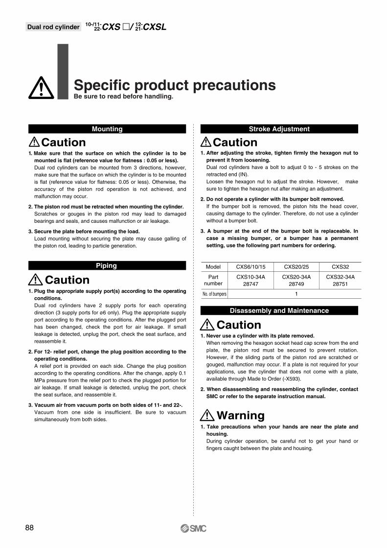
1. Plug the appropriate supply port(s) according to the operating
conditions. Dual rod cylinders have 2 supply ports for each operating direction (3 supply ports for ø6 only). Plug the appropriate supply port according to the operating conditions. After the plugged port has been changed, check the port for air leakage. If small leakage is detected, unplug the port, check the seat surface, and reassemble it.
2. For 12- relief port, change the plug position according to the
operating conditions.
A relief port is provided on each side. Change the plug position according to the operating conditions. After the change, apply 0.1 MPa pressure from the relief port to check the plugged portion for air leakage. If small leakage is detected, unplug the port, check the seat surface, and reassemble it.
3. Vacuum air from vacuum ports on both sides of 11- and 22-.
Vacuum from one side is insufficient. Be sure to vacuum simultaneously from both sides.
Caution
Caution
Warning
Model
No. of bumpers
Partnumber
CXS6/10/15
CXS10-34A28747
CXS20/25
1
CXS20-34A28749
CXS32
CXS32-34A28751
1. Take precautions when your hands are near the plate and
housing.
During cylinder operation, be careful not to get your hand or fingers caught between the plate and housing.
1. Never use a cylinder with its plate removed.
When removing the hexagon socket head cap screw from the end plate, the piston rod must be secured to prevent rotation. However, if the sliding parts of the piston rod are scratched or gouged, malfunction may occur. If a plate is not required for your applications, use the cylinder that does not come with a plate, available through Made to Order (-X593).
2. When disassembling and reassembling the cylinder, contact
SMC or refer to the separate instruction manual.
1. After adjusting the stroke, tighten firmly the hexagon nut to
prevent it from loosening.
Dual rod cylinders have a bolt to adjust 0 to - 5 strokes on the retracted end (IN). Loosen the hexagon nut to adjust the stroke. However, make sure to tighten the hexagon nut after making an adjustment.
2. Do not operate a cylinder with its bumper bolt removed.
If the bumper bolt is removed, the piston hits the head cover, causing damage to the cylinder. Therefore, do not use a cylinder without a bumper bolt.
3. A bumper at the end of the bumper bolt is replaceable. In
case a missing bumper, or a bumper has a permanent
setting, use the following part numbers for ordering.
Caution Caution
Specific product precautionsBe sure to read before handling.
Mounting Stroke Adjustment
1. Make sure that the surface on which the cylinder is to be
mounted is flat (reference value for flatness : 0.05 or less).
Dual rod cylinders can be mounted from 3 directions, however, make sure that the surface on which the cylinder is to be mounted is flat (reference value for flatness: 0.05 or less). Otherwise, the accuracy of the piston rod operation is not achieved, and malfunction may occur.
2. The piston rod must be retracted when mounting the cylinder.
Scratches or gouges in the piston rod may lead to damaged bearings and seals, and causes malfunction or air leakage.
3. Secure the plate before mounting the load.
Load mounting without securing the plate may cause galling of the piston rod, leading to particle generation.
88
Dual rod cylinder CXSL12-21-CXS �/10-/11-
22-
Piping
Disassembly and Maintenance

How to Order
CXS LJ
Auto switch specifications (Refer to Best Pneumatics No. 7 to 12 for detailed specifications and auto switches not in the following table.)
Special function
—
—
Electrical entry
Grommet
Grommet
Indicator light
Yes
Yes
Style
Reed switch
Solid state switch
Wiring(Output)
2-wire
3-wire (NPN)
2-wire
12V
Horizontal
A93
M9N
M9B
—
—
—
�
�
�
�
�
�—
100V
12V
12V
24V
24V
Load voltage
ACDC
Lead wire length (m)∗
0.5Nil
3(L)
Applicable load
∗ Lead wire symbol 0.5m………Nil (Example) A93 3m…………L A93L
PLC: Programmable Logic Controller
Auto switch modelElectrical entry direction
Relay, PLC
Relay, PLC
5(Z)
21
CXS 6 50J11
Specifications
Air (Non-lube)
1.05MPa
0.7MPa
–10°C to 60°C (With no condensation)
30 to 400 mm/s
Rubber bumper
6
0.15MPa
M3 x 0.5
10
0.1MPa
M5 x 0.80 to -5mm compared to the standard stroke
∗The maximum piston speed shown in the table above applies to the extension side. The maximum piston speed for retraction is approximately 70% that of extension.
11-/12-21-/22-
6 50 M9B S
L M9B S
11-/12-: Fluorine grease21-/22-: Lithium soap base grease
12-: Grade 2, 21-: Grade 3
11-/22-: Grade 1
715
Size Suction flow rate l/min (ANR)610
Suction flow rate of vacuum suction type(Reference values)
Nil
S
n
Number of auto switches
2 pcs.1 pc.n pcs.
Type of auto switch
Nil Without auto switch (Built-in magnet)∗ Select the applicable auto switch from the table below.
M
L∗
Bearing type
Slide BearingBall bushing bearing
∗ Only ball bushing bearing is available for series 12- and 21-.
Compact Cylinder
11
12
Vacuum suction typeRelief type(with specially treated sliding parts)
Clean series
21
22
Relief typeVacuum suction type
Copper, fluorine andsilicon-free +
low particle generation
Bore size6
10
Bore size / Stroke
Standard stroke10, 20, 30, 40, 5010, 20, 30, 40, 50
(mm)
Refer to applicable auto switch list — Page 182.
76
Bore size mm
Fluid
Proof pressure
Max. operating pressure
Min. operating pressure
Ambient and fluid temperature
Piston speed
Cushion
Stroke adjustable range
Port size
Grease
Particle generation grade (Refer to front matter pages 13 to 22 for details.)
—
—
—
Dual rod cylinder/Compact typeø6, ø10Series CXSJ
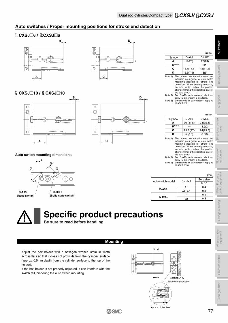
A
A Section A-ABolt holder (movable)
Approx. 0.5 or less
D-A9319(20)
—14.5(15.5)
6.5(7.5)
D-M9�23(24)
2(1)13(11.5)
8(9)
A
B
C
D
Symbol
CXSJ�6 / CXSJ�6
CXSJ�10 / CXSJ�10
11-12-
21-22-
11-12-
21-22-
Auto switch mounting dimensions
C
D
A
B
B
A C
D
(mm)
Note 1)
D-A9330 (31.5)
—25.5 (27)
5 (6.5)
D-M9�34(35.5)
3.5(2)24(25.5)
6.5(8)
A
B
C
D
Symbol
(mm)
Note 1)
Symbol
A1A2, A3
B1B2
Bore size6, 100.40.30.40.3
D-A93
D-M9�
Auto switch model
(mm)
D-A93
(Reed switch)
D-M9�(Solid state switch)
A1
A3
A2
B2
B1
Auto switches / Proper mounting positions for stroke end detection
Dual rod cylinder/Compact type CXSJ21-22-CXSJ/11-
12-
The above mentioned values are indicated as a guide for auto switch mounting position for stroke end detection. When actually mounting an auto switch, adjust the position after confirming the operating state of the auto switch. For D-A93, only outward electrical entry (D dimension) is available.Dimensions in parentheses apply to 12-CXSJ�6.
The above mentioned values are indicated as a guide for auto switch mounting position for stroke end detection. When actually mounting an auto switch, adjust the position after confirming the operating state of the auto switch. For D-A93, only outward electrical entry (D dimension) is available.Dimensions in parentheses apply to 12-CXSJ�10.
77
Mounting
Adjust the bolt holder with a hexagon wrench 3mm in width across flats so that it does not protrude from the cylinder surface (approx. 0.5mm depth from the cylinder surface to the top of the holder).If the bolt holder is not properly adjusted, it can interfere with the switch rail, hindering the auto switch mounting.
Specific product precautionsBe sure to read before handling.
Note 1)
Note 2)
Note 3)
Note 1)
Note 2)
Note 3)
Air
cylin
der
Rot
ary
actu
ator
Air
grip
per
Dire
ctio
nal c
ontr
olva
lve
Fitt
ings
& T
ubin
gP
ress
ure
switc
hC
lean
gas
filte
rF
low
con
trol
equi
pmen
tF
ilter
, Pre
ssur
eco
ntro
l equ
ipm
ent
Air
prep
arat
ion
equi
pmen
t
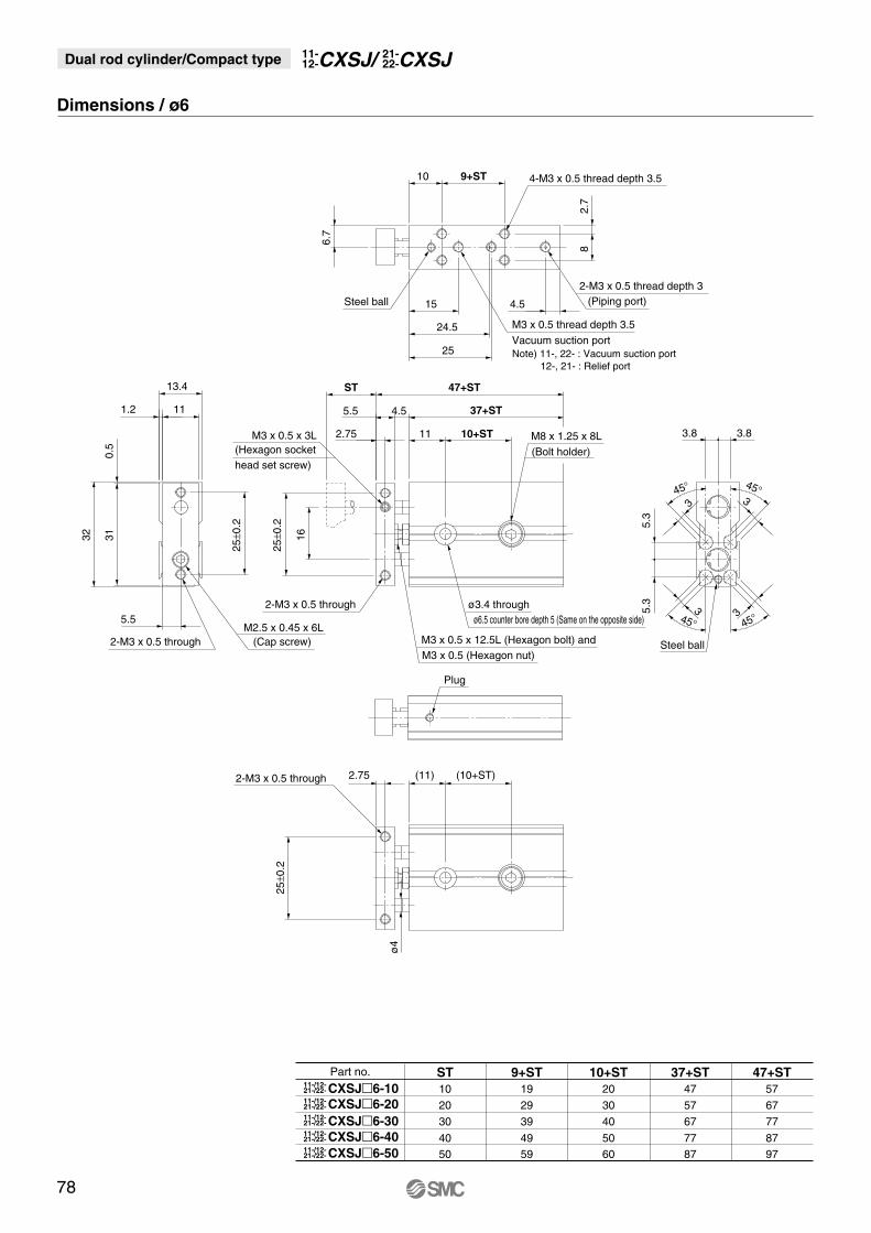
Dimensions / ø6
Part no. ST
10
20
30
4050
9+ST
19
29
39
4959
10+ST
20
30
40
5060
37+ST
47
57
67
7787
47+ST
57
67
77
8797
Note) 11-, 22- : Vacuum suction port 12-, 21- : Relief port
ø6.5 counter bore depth 5 (Same on the opposite side)ø3.4 through
Plug
2-M3 x 0.5 through
2-M3 x 0.5 through 2.75 (11) (10+ST)
2-M3 x 0.5 through
10 9+ST
4.515
ST13.4
111.2
5.5
5.5 4.5
112.75
47+ST
37+ST
10+ST 3.8 3.8
45°
45°
45°
45°
3
3
3
3
24.5
25
M3 x 0.5 x 3L
4-M3 x 0.5 thread depth 3.5
M3 x 0.5 thread depth 3.5
Vacuum suction port
2-M3 x 0.5 thread depth 3(Piping port)Steel ball
Steel ball
(Hexagon socket head set screw)
M2.5 x 0.45 x 6L(Cap screw) M3 x 0.5 x 12.5L (Hexagon bolt) and
M3 x 0.5 (Hexagon nut)
M8 x 1.25 x 8L
(Bolt holder)
6.7
25±0
.2
25±0
.2
25±0
.2
ø4
16
5.3
5.3
310.
5
32
82.
7
CXSJ�6-1021-/22-11-/12-
21-/22-11-/12-
21-/22-11-/12-
21-/22-11-/12-
21-/22-11-/12-
CXSJ�6-20
CXSJ�6-30
CXSJ�6-40
CXSJ�6-50
Dual rod cylinder/Compact type CXSJ21-22-CXSJ/11-
12-
78
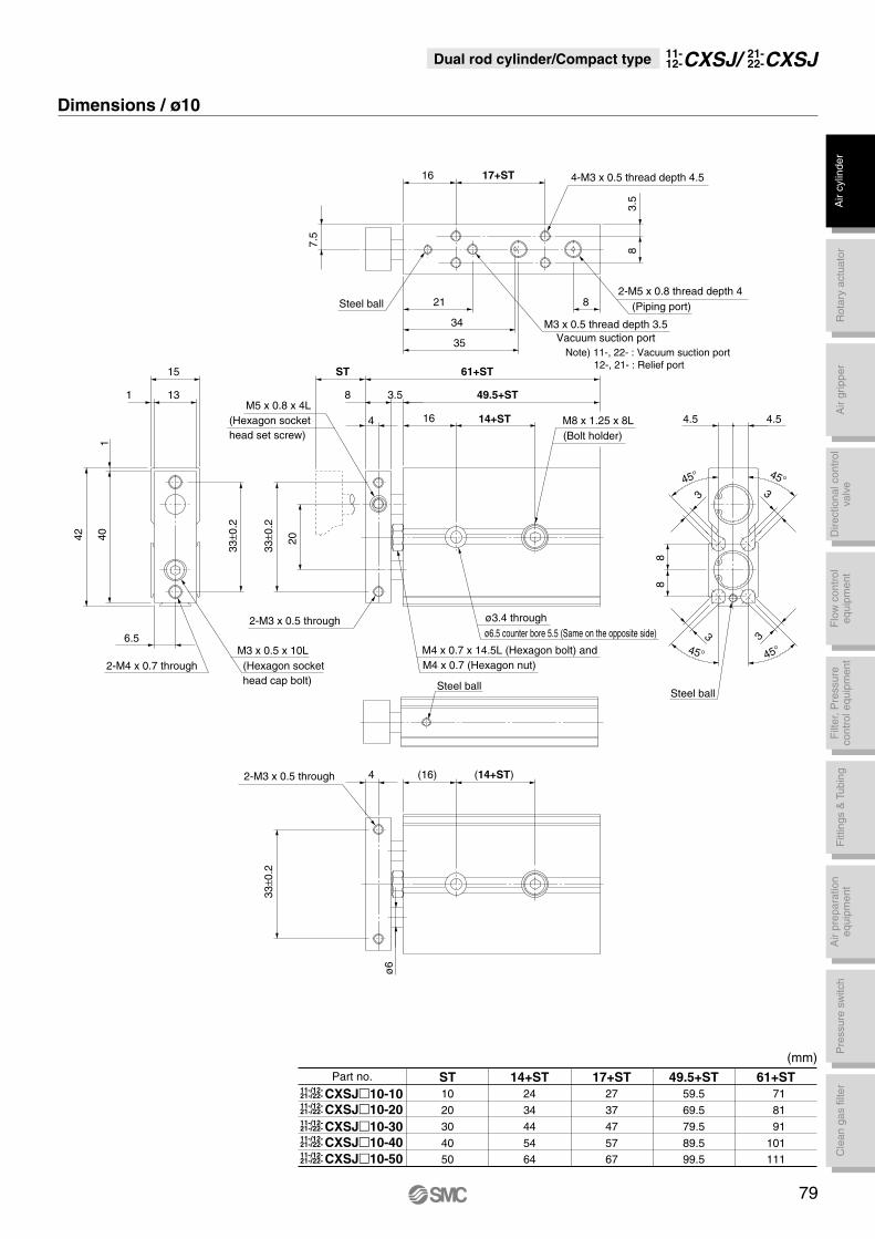
Dimensions / ø10
(mm)Part no.
CXSJ�10-1021-/22-11-/12-
CXSJ�10-2021-/22-11-/12-
CXSJ�10-3021-/22-11-/12-
CXSJ�10-4021-/22-11-/12-
CXSJ�10-5021-/22-11-/12-
ST
10
20
30
4050
14+ST
24
34
44
5464
17+ST
27
37
47
5767
49.5+ST
59.5
69.5
79.5
89.599.5
61+ST
71
81
91
101111
Note) 11-, 22- : Vacuum suction port 12-, 21- : Relief port
ø6.5 counter bore 5.5 (Same on the opposite side)ø3.4 through
2-M4 x 0.7 through
6.5
2-M3 x 0.5 through
2-M3 x 0.5 through
16 17+ST
4 16
61+ST
21 8
34
35
ST
49.5+ST3.58
14+ST 4.5 4.5
45°
45°
45°
45°
3
3
3
3
M5 x 0.8 x 4L
15
131
4-M3 x 0.5 thread depth 4.5
M3 x 0.5 thread depth 3.5Vacuum suction port
2-M5 x 0.8 thread depth 4(Piping port)
(Hexagon socket head set screw)
M3 x 0.5 x 10L(Hexagon sockethead cap bolt)
M4 x 0.7 x 14.5L (Hexagon bolt) andM4 x 0.7 (Hexagon nut)
M8 x 1.25 x 8L(Bolt holder)
7.5
3.5
8
33±0
.233
±0.2
ø6
(14+ST)(16)4
33±0
.2
8
14042 20
8
Steel ball
Steel ballSteel ball
Dual rod cylinder/Compact type CXSJ21-22-CXSJ/11-
12-
79
Air
cylin
der
Rot
ary
actu
ator
Air
grip
per
Dire
ctio
nal c
ontr
olva
lve
Fitt
ings
& T
ubin
gP
ress
ure
switc
hC
lean
gas
filte
rF
low
con
trol
equi
pmen
tF
ilter
, Pre
ssur
eco
ntro
l equ
ipm
ent
Air
prep
arat
ion
equi
pmen
t