Dual Purpose Desktop Machine – 3D Printer and CNC...
8
Proceedings of the 2014 ASEE North Central Section Conference Copyright ©2014, American Society for Engineering Education 1 Dual Purpose Desktop Machine – 3D Printer and CNC Milling Austin Grieve, Kenneth Klingler, Miguel Acuna, Pavel Ikonomov, and Jorge Rodriguez Department of Industrial and Manufacturing Engineering Western Michigan University Kalamazoo, MI 49008-5336 [email protected] Abstract Because of the increase in demand of machines for personal use, and due to the fact that machines with combined processes are not yet sold in this niche market. Many consumers, especially in industry, possess manufacturing processes on completely different machines, and few attempt to retrofit one for the other process. The dual-purpose desktop machine is the result of combining 3D printing and CNC milling, two popular processes, in a useful DIY format for in-home manufacturing. With the popularity of people making their own parts at home and the ease of buying components and machines in today’s world, even those without experience in these processes can jump in and learn about personal manufacturing. Important aspects considered were the common components of 3D printing and milling machines, and the crucial acquisition of these components in a form that would allow both processes to work. The machine will be an important learning tool for classrooms and a resource to expose students to manufacturing technologies. It also serves as a level of comparison to existing, available products on the market. Lastly, the machine fits with in-home manufacturing by having a smaller footprint, easy operation, and interchangeability of the processes. Introduction Additive (material formation) and subtractive (material removal) manufacturing technologies have been popularly employed in a variety of fields such as prototyping modeling artistry, education, decoration, medicine, and direct production. These manufacturing technologies exist as independent machines of large sizes, different structural components, industrial capacities, professional-skill functionalities, and high costs. However, the field of do-it-yourself (DIY) manufacturing is expanding and creating a demand for personal, desktop-sized machines available to the general consumer 1 . Desktop machines employing subtractive and additive manufacturing processes have become popular for use by hobbyists, but each process requires a separate machine. In addition, open- source technology has made available hundreds of these newly-emerging machines. But these models also come in a variety of sizes, shapes, capacities, functionalities, and prices; and they are offered by professional companies to DIY enthusiasts spread around the world.
Transcript of Dual Purpose Desktop Machine – 3D Printer and CNC...

Proceedings of the 2014 ASEE North Central Section Conference
Copyright ©2014, American Society for Engineering Education 1
Dual Purpose Desktop Machine – 3D Printer and CNC Milling
Austin Grieve, Kenneth Klingler, Miguel Acuna, Pavel Ikonomov, and Jorge Rodriguez Department of Industrial and Manufacturing Engineering
Western Michigan University Kalamazoo, MI 49008-5336 [email protected]
Abstract Because of the increase in demand of machines for personal use, and due to the fact that machines with combined processes are not yet sold in this niche market. Many consumers, especially in industry, possess manufacturing processes on completely different machines, and few attempt to retrofit one for the other process. The dual-purpose desktop machine is the result of combining 3D printing and CNC milling, two popular processes, in a useful DIY format for in-home manufacturing. With the popularity of people making their own parts at home and the ease of buying components and machines in today’s world, even those without experience in these processes can jump in and learn about personal manufacturing. Important aspects considered were the common components of 3D printing and milling machines, and the crucial acquisition of these components in a form that would allow both processes to work. The machine will be an important learning tool for classrooms and a resource to expose students to manufacturing technologies. It also serves as a level of comparison to existing, available products on the market. Lastly, the machine fits with in-home manufacturing by having a smaller footprint, easy operation, and interchangeability of the processes.
Introduction Additive (material formation) and subtractive (material removal) manufacturing technologies have been popularly employed in a variety of fields such as prototyping modeling artistry, education, decoration, medicine, and direct production. These manufacturing technologies exist as independent machines of large sizes, different structural components, industrial capacities, professional-skill functionalities, and high costs. However, the field of do-it-yourself (DIY) manufacturing is expanding and creating a demand for personal, desktop-sized machines available to the general consumer1. Desktop machines employing subtractive and additive manufacturing processes have become popular for use by hobbyists, but each process requires a separate machine. In addition, open-source technology has made available hundreds of these newly-emerging machines. But these models also come in a variety of sizes, shapes, capacities, functionalities, and prices; and they are offered by professional companies to DIY enthusiasts spread around the world.

Proceedings of the 2014 ASEE North Central Section Conference
Copyright ©2014, American Society for Engineering Education 2
The popularity of additive and subtractive technologies, combined with the growth of DIY manufacturing, has made three-dimensional (3D) printing and computer-numerical-control (CNC) milling the most desirable technologies for personal use3. Therefore, this project sought to combine CNC milling and 3D printing into one machine; bringing together frame, hardware, controls, and software to operate each process. Staying true to the spirit of DIY manufacturing, the machine’s criteria were defined to have a desktop footprint, an approximate build capacity of 11x11x11 inches, easy access to the product, a flexible interchangeability of the tools, and a focus on plastic, wood, and soft metals as production materials.
Background The two processes applied in this work are 3D printing and CNC milling. Briefly:
• 3D printing, a form of additive manufacturing2, is the processes of creating a part through the addition of material. 3D printed parts can be made of powder, gels, plastics, and metal. This technology is becoming more common in industry. The most popular type of 3D printing is done through fused deposition, which is the melting of plastic through a heated nozzle to lay down layers of material on top of each other to form an object. Since 2005, the 3D printing market has been growing and expanding, which has made available hundreds of personal 3D printers.
• CNC milling is the removal of material through the use of cutters rotating at high speeds. This process is a form of subtractive manufacturing. Materials used for production are generally foam, plastics, wood and metal. These machines are used for prototyping, mass production, mold making and producing custom parts. Manual mills have been used for most of the 20th century, with the advent of computer numerical control coming around the midpoint of the century.
The motion of both 3D printing and CNC milling is controlled through the same programming language. Known as G-code, this programming language is based on the cartesian coordinate system (X, Y, & Z), which is used by a variety of other machining and manufacturing processes. This allows implementing other technologies, such as laser engraving and coordinate measuring, on the same machine. However, research showed that in order to have laser engraving capability, an exhaust system and a casing were needed to get rid of potentially toxic fumes emitted from the laser and burning material, and to enclose the working area, respectively. Coordinate measuring capabilities were also halted due to the high cost of a single touching probe.
Design Procedure The machine needed to be strong enough to be able to cut through light metals, and yet precise enough create accurate parts. To accomplish this, the frame was made out of 8020 aluminum extrusions (top, left) due to its great strength-to-weight ratio, ease of assembly, and flexible arrangement4. The conversion of rotational motion, from the motors, to linear travel was accomplished by the use of ball screws5. The nut of a ball screw contains numerous ball bearings that roll along the threads of the screw, allowing for greatly reduced friction, high precision, and high efficiency.
Proceedings of the 2014 ASEE North Central Section Conference
Copyright ©2014, American Society for Engineering Education 3
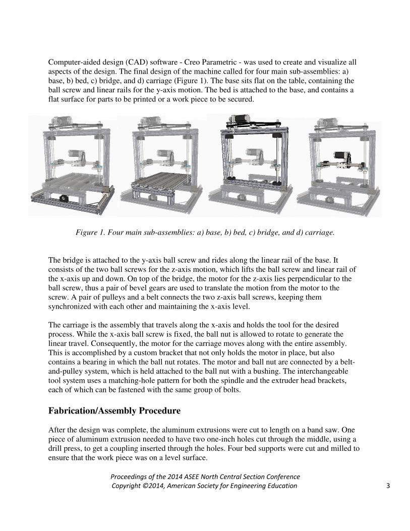
Computer-aided design (CAD) software - Creo Parametric - was used to create and visualize all aspects of the design. The final design of the machine called for four main sub-assemblies: a) base, b) bed, c) bridge, and d) carriage (Figure 1). The base sits flat on the table, containing the ball screw and linear rails for the y-axis motion. The bed is attached to the base, and contains a flat surface for parts to be printed or a work piece to be secured.
Figure 1. Four main sub-assemblies: a) base, b) bed, c) bridge, and d) carriage.
The bridge is attached to the y-axis ball screw and rides along the linear rail of the base. It consists of the two ball screws for the z-axis motion, which lifts the ball screw and linear rail of the x-axis up and down. On top of the bridge, the motor for the z-axis lies perpendicular to the ball screw, thus a pair of bevel gears are used to translate the motion from the motor to the screw. A pair of pulleys and a belt connects the two z-axis ball screws, keeping them synchronized with each other and maintaining the x-axis level. The carriage is the assembly that travels along the x-axis and holds the tool for the desired process. While the x-axis ball screw is fixed, the ball nut is allowed to rotate to generate the linear travel. Consequently, the motor for the carriage moves along with the entire assembly. This is accomplished by a custom bracket that not only holds the motor in place, but also contains a bearing in which the ball nut rotates. The motor and ball nut are connected by a belt-and-pulley system, which is held attached to the ball nut with a bushing. The interchangeable tool system uses a matching-hole pattern for both the spindle and the extruder head brackets, each of which can be fastened with the same group of bolts.
Fabrication/Assembly Procedure
After the design was complete, the aluminum extrusions were cut to length on a band saw. One piece of aluminum extrusion needed to have two one-inch holes cut through the middle, using a drill press, to get a coupling inserted through the holes. Four bed supports were cut and milled to ensure that the work piece was on a level surface.
Proceedings of the 2014 ASEE North Central Section Conference
Copyright ©2014, American Society for Engineering Education 4
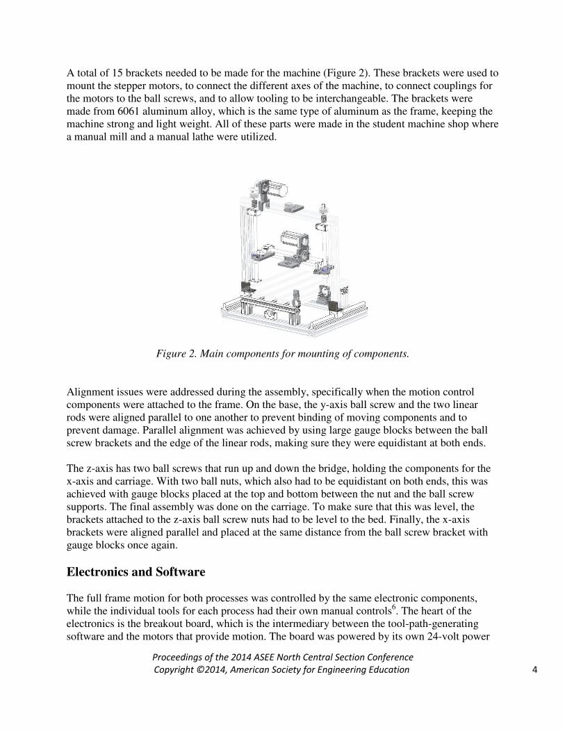
A total of 15 brackets needed to be made for the machine (Figure 2). These brackets were used to mount the stepper motors, to connect the different axes of the machine, to connect couplings for the motors to the ball screws, and to allow tooling to be interchangeable. The brackets were made from 6061 aluminum alloy, which is the same type of aluminum as the frame, keeping the machine strong and light weight. All of these parts were made in the student machine shop where a manual mill and a manual lathe were utilized.
Figure 2. Main components for mounting of components.
Alignment issues were addressed during the assembly, specifically when the motion control components were attached to the frame. On the base, the y-axis ball screw and the two linear rods were aligned parallel to one another to prevent binding of moving components and to prevent damage. Parallel alignment was achieved by using large gauge blocks between the ball screw brackets and the edge of the linear rods, making sure they were equidistant at both ends. The z-axis has two ball screws that run up and down the bridge, holding the components for the x-axis and carriage. With two ball nuts, which also had to be equidistant on both ends, this was achieved with gauge blocks placed at the top and bottom between the nut and the ball screw supports. The final assembly was done on the carriage. To make sure that this was level, the brackets attached to the z-axis ball screw nuts had to be level to the bed. Finally, the x-axis brackets were aligned parallel and placed at the same distance from the ball screw bracket with gauge blocks once again.
Electronics and Software The full frame motion for both processes was controlled by the same electronic components, while the individual tools for each process had their own manual controls6. The heart of the electronics is the breakout board, which is the intermediary between the tool-path-generating software and the motors that provide motion. The board was powered by its own 24-volt power
Proceedings of the 2014 ASEE North Central Section Conference
Copyright ©2014, American Society for Engineering Education 5
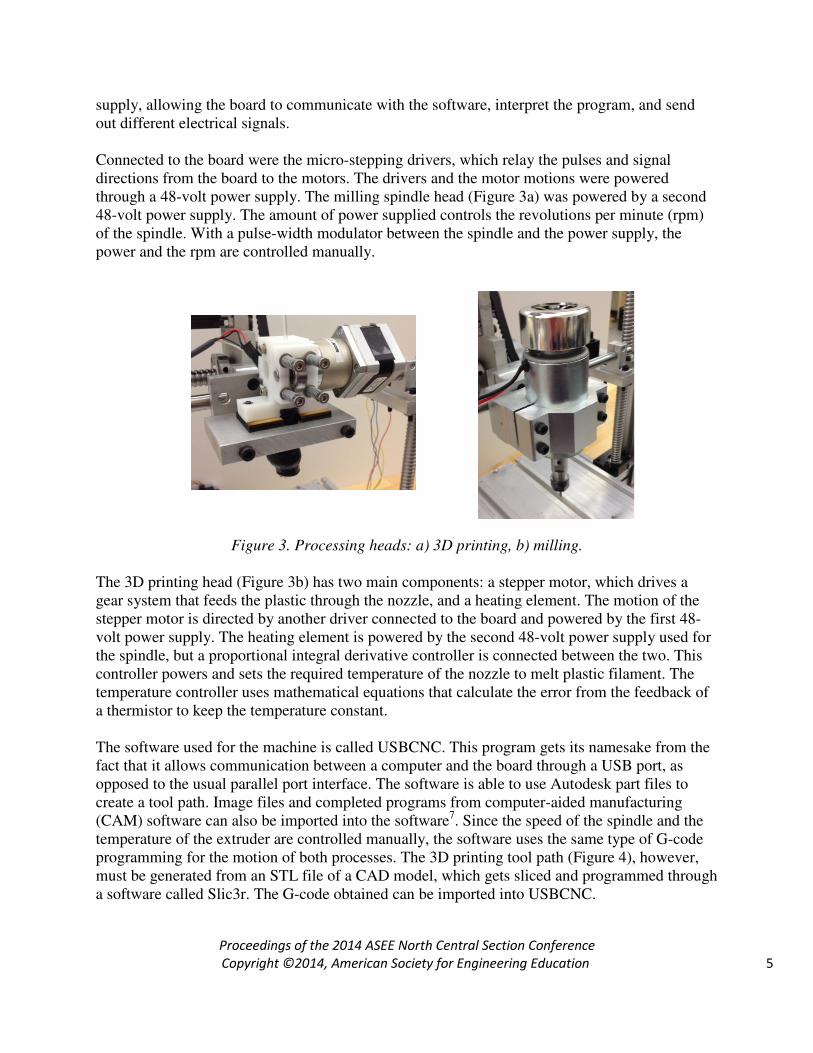
supply, allowing the board to communicate with the software, interpret the program, and send out different electrical signals. Connected to the board were the micro-stepping drivers, which relay the pulses and signal directions from the board to the motors. The drivers and the motor motions were powered through a 48-volt power supply. The milling spindle head (Figure 3a) was powered by a second 48-volt power supply. The amount of power supplied controls the revolutions per minute (rpm) of the spindle. With a pulse-width modulator between the spindle and the power supply, the power and the rpm are controlled manually.
Figure 3. Processing heads: a) 3D printing, b) milling.
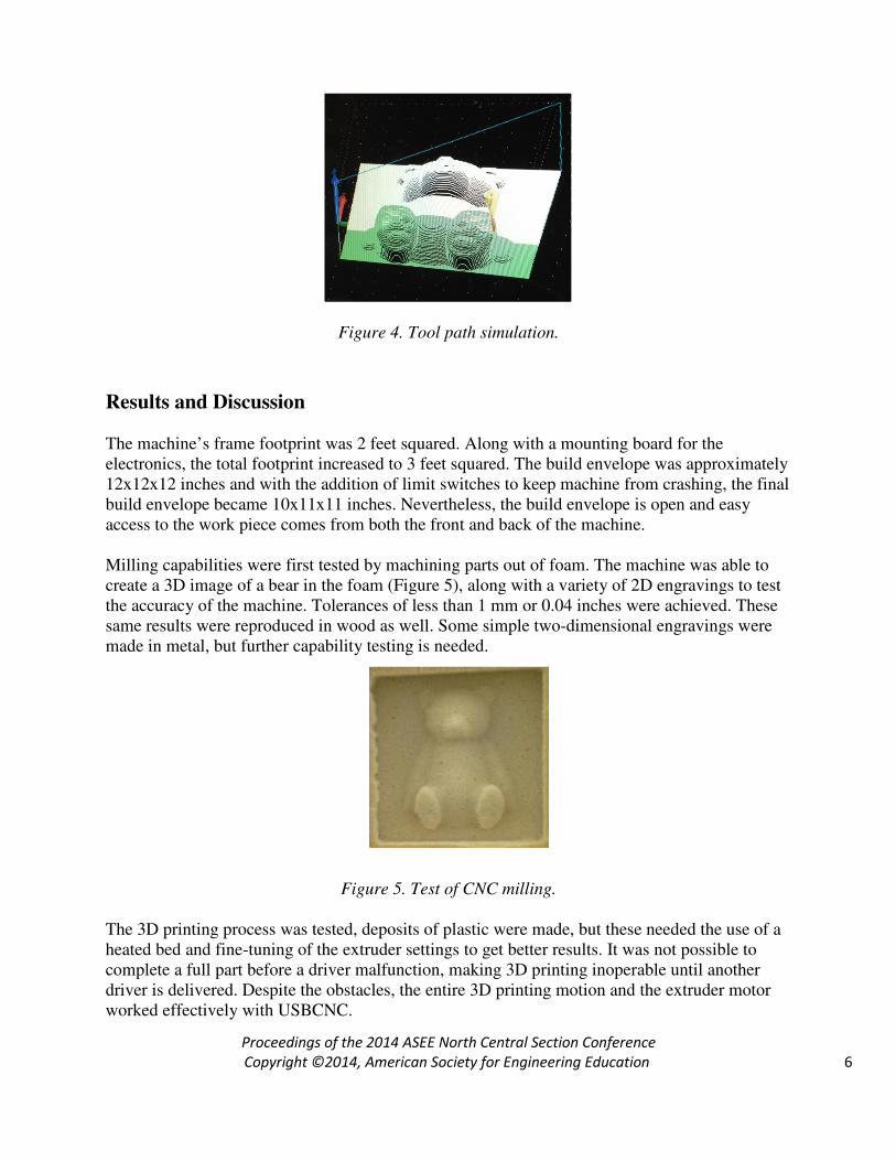
The 3D printing head (Figure 3b) has two main components: a stepper motor, which drives a gear system that feeds the plastic through the nozzle, and a heating element. The motion of the stepper motor is directed by another driver connected to the board and powered by the first 48-volt power supply. The heating element is powered by the second 48-volt power supply used for the spindle, but a proportional integral derivative controller is connected between the two. This controller powers and sets the required temperature of the nozzle to melt plastic filament. The temperature controller uses mathematical equations that calculate the error from the feedback of a thermistor to keep the temperature constant. The software used for the machine is called USBCNC. This program gets its namesake from the fact that it allows communication between a computer and the board through a USB port, as opposed to the usual parallel port interface. The software is able to use Autodesk part files to create a tool path. Image files and completed programs from computer-aided manufacturing (CAM) software can also be imported into the software7. Since the speed of the spindle and the temperature of the extruder are controlled manually, the software uses the same type of G-code programming for the motion of both processes. The 3D printing tool path (Figure 4), however, must be generated from an STL file of a CAD model, which gets sliced and programmed through a software called Slic3r. The G-code obtained can be imported into USBCNC.
Proceedings of the 2014 ASEE North Central Section Conference
Copyright ©2014, American Society for Engineering Education 6
Figure 4. Tool path simulation.
Results and Discussion
The machine’s frame footprint was 2 feet squared. Along with a mounting board for the electronics, the total footprint increased to 3 feet squared. The build envelope was approximately 12x12x12 inches and with the addition of limit switches to keep machine from crashing, the final build envelope became 10x11x11 inches. Nevertheless, the build envelope is open and easy access to the work piece comes from both the front and back of the machine. Milling capabilities were first tested by machining parts out of foam. The machine was able to create a 3D image of a bear in the foam (Figure 5), along with a variety of 2D engravings to test the accuracy of the machine. Tolerances of less than 1 mm or 0.04 inches were achieved. These same results were reproduced in wood as well. Some simple two-dimensional engravings were made in metal, but further capability testing is needed.
Figure 5. Test of CNC milling.
The 3D printing process was tested, deposits of plastic were made, but these needed the use of a heated bed and fine-tuning of the extruder settings to get better results. It was not possible to complete a full part before a driver malfunction, making 3D printing inoperable until another driver is delivered. Despite the obstacles, the entire 3D printing motion and the extruder motor worked effectively with USBCNC.
Proceedings of the 2014 ASEE North Central Section Conference
Copyright ©2014, American Society for Engineering Education 7
Each of the tooling is connected by a set of nuts and bolts with the same hole-pattern onto a bracket, allowing each process to be changed as desired. The functionality of each process is ensured by properly connecting the electronics to their respective power supplies, and by setting up the manual controls. In USBCNC, the fourth axis of motion must be either enabled for 3D printing or disabled for milling. At this point, a program can be created and run.
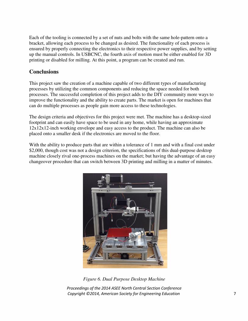
Conclusions This project saw the creation of a machine capable of two different types of manufacturing processes by utilizing the common components and reducing the space needed for both processes. The successful completion of this project adds to the DIY community more ways to improve the functionality and the ability to create parts. The market is open for machines that can do multiple processes as people gain more access to these technologies. The design criteria and objectives for this project were met. The machine has a desktop-sized footprint and can easily have space to be used in any home, while having an approximate 12x12x12-inch working envelope and easy access to the product. The machine can also be placed onto a smaller desk if the electronics are moved to the floor. With the ability to produce parts that are within a tolerance of 1 mm and with a final cost under $2,000, though cost was not a design criterion, the specifications of this dual-purpose desktop machine closely rival one-process machines on the market; but having the advantage of an easy changeover procedure that can switch between 3D printing and milling in a matter of minutes.
Figure 6. Dual Purpose Desktop Machine
Proceedings of the 2014 ASEE North Central Section Conference
Copyright ©2014, American Society for Engineering Education 8
Acknowledgements The dual-purpose desktop machine was made possible thanks to the guidance from Peter Thannhauser and Abraham Poot for their assistance in electronics, and to Glenn Hall and Mike Konkel for their help in the machine shop. Finally, our gratitude goes out to the Office of the Vice President for Research (WMU) and to Misumi USA for their financial assistance.
Bibliography 1. Anderson, C. (2012). Makers: The new industrial revolution. N.p.: Crown Business. 2. ASTM Standard F2792-12a (2009). Standard terminology for additive manufacturing technologies. ASTM International, West Conshohocken, PA, 2003, DOI: 10.1520/F2792-12A. 3. Bradshaw, S., Bowyer, A. & Haufe, P. (2010) The intellectual property implications of low-cost 3D printing. 7:1 SCRIPTed 5, http://www.law.ed.ac.uk/ahrc/script-ed/vol7-1/bradshaw.asp. 4. Devijver, S. (2011). Building your own 3D printer. In RepRap. Retrieved March 19, 2013, from http://reprapbook.appspot.com/#d0e148. 5. Patrick Scott (2005). The straight story on ball screws. Motion System Design. Vol. 47, Issue 12, p 19. 6. R. Breaz, G. Racz, O. Bologa, V. Oleksik (2012). Motion Control of medium size CNC Machine-tools – A hands on approach. 2012 7
th IEEE Conference on Industrial Electronics and Applications. ICIEA 2012, p 2112-2117.
7. X. Xu, H. Wang, J. Mao, S. Newman, T. Kramer, F. Proctor, J. Michaloski (2005). STEP-compliant NC research: The search for intelligent CAD/CAPP/CAM/CNC integration. International Journal of Production Research, Vol. 43, Issue 17, p 3703-3743.