Analisis Mitigasi Voltage Sagmenggunakan Dynamic Voltage Restorer (Dvr)

0278-0046 (c) 2018 IEEE. Personal use is permitted, but republication/redistribution requires IEEE permission. See http://www.ieee.org/publications_standards/publications/rights/index.html for more information.
This article has been accepted for publication in a future issue of this journal, but has not been fully edited. Content may change prior to final publication. Citation information: DOI 10.1109/TIE.2018.2850009, IEEETransactions on Industrial Electronics
Dual P -Q Theory based Energy OptimizedDynamic Voltage Restorer for Power Quality
Improvement in Distribution SystemManik Pradhan, Student Member, IEEE, and Mahesh K. Mishra, Senior Member, IEEE
Abstract—This paper deals with the protection of crit-ical loads from voltage related power quality issues us-ing Dynamic Voltage Restorer (DVR). A generalized con-trol algorithm based on Instantaneous Space Phasor (ISP)and dual P -Q theory has been proposed to generate theinstantaneous reference voltages to compensate the loadvoltages with direct power flow control. The proposed al-gorithm adapts energy optimized series voltage compen-sation, which results in a reduction of energy storagerequirement. The proposed DVR control scheme can sup-port the load from voltage related power quality issuesirrespective of the load current profile. Each leg of thethree-phase three-leg split capacitor inverter is used toinject series compensation voltage in respective phases ofthe system. Model-based computer simulation studies andreal-time experimental results validate the effectiveness ofthe proposed control algorithm.
Index Terms—Active power filter, brownout, dual P-Q the-ory, dynamic voltage restorer (DVR), instantaneous spacephasor (ISP), load voltage compensation, power quality,sag, swell.
I. INTRODUCTION
Modern domestic and industrial equipment are quite sen-sitive to voltage disturbances. Even a one-hundredth of asecond voltage sag can halt modern equipment, which re-sults in a complete restart of an industrial process. As aresult, maintenance of power quality in the distribution systembecomes an inescapably important requirement [1]. Powerquality is a broad term, comprises various types of voltage andcurrent related disturbances such as voltage sag/swell, flicker,voltage unbalance, harmonic current and poor power-factor,etc. Among these power quality problems, voltage relateddisturbance causes serious disruption on sensitive load andvoltage sag is the most frequently occurring voltage relatedpower quality problem thereof [2], [3].
As per the IEEE 519 [4] standard, different types of custompower devices are used to improve the power quality in theconsumer premises [5–7]. Dynamic Voltage Restorer (DVR),one of the aforesaid devices, is used to protect the critical
Manuscript received November 20, 2017; revised February 24, 2018and May 5, 2018; accepted Jun 1, 2018. This work is supportedby the Department of Science and Technology, India (Project grant:IUSSTF/JCERDC-Smart Grids and Energy Storage/2017).
M. Pradhan and Mahesh K. Mishra are with the Departmentof Electrical Engineering, Indian Institute of Technology Madras,Chennai 600036, India(e-mail: [email protected] and [email protected]).
fL
Cf
s sVfe
Vse Vle IleVte
VDC
Ise
Fig. 1. Single line diagram of general Dynamic Voltage Restorer (DVR)circuit.
load (digital communication networks, advanced medical in-struments, financial transactions system, elevator etc.) fromvoltage related power quality issues [8]. The DVR is connectedin series with the grid terminal before the critical loads and in-jects the required amount of compensating voltage to maintainthe load voltage within the specified value. A DVR generallyconsists of DC energy storage device, voltage source inverter(VSI), passive filter components and injection transformer. Asingle line diagram of a DVR circuit is shown in Fig. 1.
With the development of DVR, numerous voltage compen-sation strategies have been presented in the literature [9–14].Based on the operation, these strategies are broadly classifiedas pre-sag, in-phase and energy optimized compensation [9],[13], [15]. As the name suggests, pre-sag compensation re-stores load voltage magnitude as well as phase angle sameas pre-sag load voltage. In order to restore the load voltagemagnitude, series injected DVR voltage is aligned with gridterminal voltage during in-phase compensation. In case ofenergy optimized compensation, DVR restores load voltagemagnitude while optimizing the active power requirement. Thecharacteristics of these strategies depend upon the injectedvoltage magnitude, phase jump and utilization of active power.Each has some advantages over others, which are brieflymentioned in Table I. If load is capable enough to withstand
TABLE ICOMPARISON BETWEEN COMPENSATION SCHEMES
Control strategy Voltage mag. Phase jump Active powerIn-phase low high highPre-sag high low high
Energy optimized high high low
some phase jumps, then energy optimized voltage compensa-tion strategy is mostly preferred as it reduces active powerrequirement as compared to others.
0278-0046 (c) 2018 IEEE. Personal use is permitted, but republication/redistribution requires IEEE permission. See http://www.ieee.org/publications_standards/publications/rights/index.html for more information.
This article has been accepted for publication in a future issue of this journal, but has not been fully edited. Content may change prior to final publication. Citation information: DOI 10.1109/TIE.2018.2850009, IEEETransactions on Industrial Electronics
Several control techniques focusing on energy optimizedcontrol algorithm or optimum rating DVR topology have beenpresented in the literature [9], [16], [17]. Depending uponthe DVR topology and structure, energy storage requirementvaries significantly [18]. A theoretical investigation of theenergy optimized control strategy for medium voltage DVR ispresented in [19]. However, voltage compensation in cases ofnonlinear loads, distorted grid voltages and switched load con-ditions which are very common in power distribution system,are not fully addressed. Self-supported DVR for unbalance andnon-linear loads are presented in [20], [21], but this involvesadditional investment on passive shunt filters. Considering thereliability aspect during under voltage or high depth voltagesag, DVR with battery energy support is presented in [22]. Inorder to improve the transient response, DVR based on hybridenergy storage system comprised of battery, supercapacitor orsuperconducting magnetic energy storage are proposed in [23],[24]. However, a robust DVR control scheme is required forsmooth energy transfer. Several new DVR topologies usingswitching cell multilevel converter [25], cascaded open endwinding transformer [26] are presented in the literature. Anenhanced voltage sag compensation scheme is proposed in[16], which mitigates phase jump in the load voltage whileimproving the sag compensation time. An interesting pre-sag load voltage compensation scheme based on ellipticaltrajectory estimation and two degrees of freedom resonantDVR control schemes are presented in [27] and [28].
On the other hand, dual of the widely accepted PQ theoryfor shunt current compensation, has not been investigatedclosely for series voltage compensation purpose. In this paper,DVR control algorithm based on the Instantaneous SpacePhasor (ISP) and Dual P -Q theory has been presented toaddress some of these aforesaid issues. The proposed al-gorithm is generalized enough to compensate instantaneousas well as long term voltage disturbances to protect thecritical loads while optimizing the active power requirement.The proposed control algorithm has been tested through thecomputer simulation software MATLAB/Simulink and real-time experiments have been performed using MicroLabBox-dSPACE to show the validity and feasibility of the algorithm.
II. CONCEPT OF INSTANTANEOUS SPACE PHASOR
Concept of instantaneous space phasor based on Clarke’stransformation, can be used to monitor electric power flow, toobserve the utilization of the transmission line, and to quantifythe level of harmonic pollution injected by nonlinear loads etc.According to the Clarke’s transformation, the power invarianttransformation in between abc and αβ0 is shown in (1) and(2). v0
vαvβ
=
√2
3
1√2
1√2
1√2
1 −12
−12
0√
32
−√
32
vavbvc
(1)
vavbvc
=
√2
3
1√2
1 01√2
−12
√3
21√2
−12
−√
32
v0
vαvβ
(2)
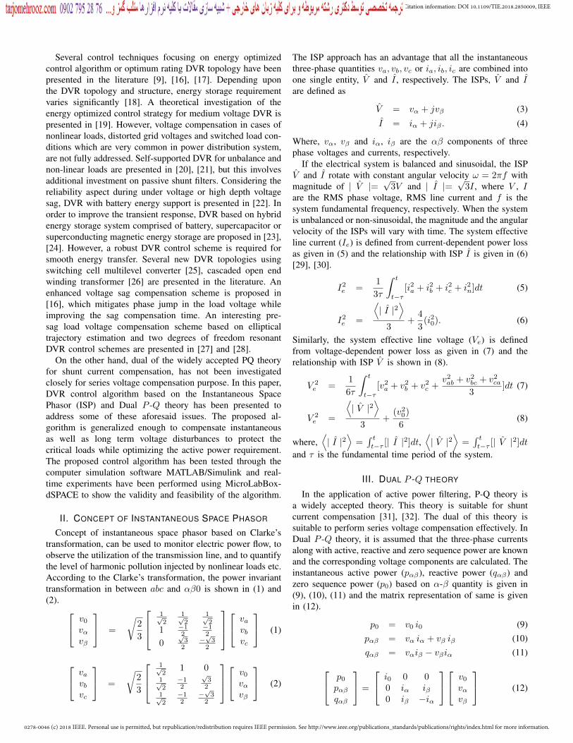
The ISP approach has an advantage that all the instantaneousthree-phase quantities va, vb, vc or ia, ib, ic are combined intoone single entity, V and I , respectively. The ISPs, V and Iare defined as
V = vα + jvβ (3)
I = iα + jiβ . (4)
Where, vα, vβ and iα, iβ are the αβ components of threephase voltages and currents, respectively.
If the electrical system is balanced and sinusoidal, the ISPV and I rotate with constant angular velocity ω = 2πf withmagnitude of | V |=
√3V and | I |=
√3I , where V , I
are the RMS phase voltage, RMS line current and f is thesystem fundamental frequency, respectively. When the systemis unbalanced or non-sinusoidal, the magnitude and the angularvelocity of the ISPs will vary with time. The system effectiveline current (Ie) is defined from current-dependent power lossas given in (5) and the relationship with ISP I is given in (6)[29], [30].
I2e =
1
3τ
∫ t
t−τ[i2a + i2b + i2c + i2n]dt (5)
I2e =
⟨| I |2
⟩3
+4
3(i20). (6)
Similarly, the system effective line voltage (Ve) is definedfrom voltage-dependent power loss as given in (7) and therelationship with ISP V is shown in (8).
V 2e =
1
6τ
∫ t
t−τ[v2a + v2
b + v2c +
v2ab + v2
bc + v2ca
3]dt (7)
V 2e =
⟨| V |2
⟩3
+(v2
0)
6(8)
where,⟨| I |2
⟩=
∫ tt−τ [| I |2]dt,
⟨| V |2
⟩=
∫ tt−τ [| V |2]dt
and τ is the fundamental time period of the system.
III. DUAL P -Q THEORY
In the application of active power filtering, P-Q theory isa widely accepted theory. This theory is suitable for shuntcurrent compensation [31], [32]. The dual of this theory issuitable to perform series voltage compensation effectively. InDual P -Q theory, it is assumed that the three-phase currentsalong with active, reactive and zero sequence power are knownand the corresponding voltage components are calculated. Theinstantaneous active power (pαβ), reactive power (qαβ) andzero sequence power (p0) based on α-β quantity is given in(9), (10), (11) and the matrix representation of same is givenin (12).
p0 = v0 i0 (9)pαβ = vα iα + vβ iβ (10)qαβ = vαiβ − vβiα (11) p0
pαβqαβ
=
i0 0 00 iα iβ0 iβ −iα
v0
vαvβ
(12)

0278-0046 (c) 2018 IEEE. Personal use is permitted, but republication/redistribution requires IEEE permission. See http://www.ieee.org/publications_standards/publications/rights/index.html for more information.
This article has been accepted for publication in a future issue of this journal, but has not been fully edited. Content may change prior to final publication. Citation information: DOI 10.1109/TIE.2018.2850009, IEEETransactions on Industrial Electronics
abc to αβ0
DVR Reference Voltage
Generation based on Dual P-Q Theory
(22)
Instantaneous Load Voltage
Generation (Fig. 3)
InstantaneousTerminal End
Power
RequiredInstantaneous Load Power
αβ0 to abcTransformatio
abc to αβ0
0tv
Hysteresis Voltage Control
0i
0lv
tabcv
lp
0
*fv
fav
fbv
fcv
4slabci
tabcv
*0dvrp
1s
3s
5s2s
lp
0lp
6s
*fv
*fv
*dvrp
*dvrq
*fav
*fbv
*fcv
0lplq
lp
lq
0lp
Fig. 2. Complete block diagram representation of the proposed control scheme.
The matrix representation of dual P -Q theory based volt-age component extraction from instantaneous active, reactivepower is derived from (12) and given in (13). v0
vαvβ
=
1i0
0 0
0 iαiα2+iβ2
iβiα2+iβ2
0iβ
iα2+iβ2 − iαiα2+iβ2
p0
pαβqαβ
(13)
IV. PROPOSED DVR CONTROL STRATEGIES
In Fig. 1, Vte, Ile, Vle and Vfe are the effective line to neutralgrid terminal voltage, line current, load voltage and DVRinjection voltage, respectively. Whereas, V ∗le is the desiredRMS line to neutral load voltage. The DC bus voltage ismaintained constant by using energy storage devices. In orderto ensure the optimum use of energy storage devices, theproposed algorithm should compensate the load voltage withoptimum utilization of active power. The overview of thecontrol algorithm is shown in Fig. 2.
A. Energy Optimized Compensation TechniqueThe system is assumed to be consisting of balanced and
linear load, with an ideal DVR circuit, which maintains therated voltages at the load end. If the system is balancedand sinusoidal, zero sequence component will be zero andthe relationship between ISPs V and I with effective voltageVeand Ie are given in (6) and (8), can be rewritten as following.
Ve =
⟨| V |
⟩√
3, Ie =
⟨| I |
⟩√
3. (14)
From the information of the effective terminal voltage (Vte)and line current (Ile), the apparent power of the grid terminalis obtained as follows:
Steff = 3VteIle. (15)
Where, Steff is the maximum active power (Ptmax) that canbe delivered by the grid. The grid terminal active power Ptand desired load active power Pl can be defined as
Pt = 3VteIle cos θ (16)Pl = 3V ∗leIle cosφeff . (17)
Where, θ is the angle between effective terminal voltage Vteand effective line current Ile and φeff is effective load powerfactor angle.
In order to supply minimum active power through theDVR, the grid should supply the total load active power Plduring normal steady-state condition. However, during voltagedisturbance, grid should supply maximum possible fractionof load active power, which is mathematically expressed asfollows:
min Pdvr(Vte, θ) = Pl − Pt
Pdvr(Vte, θ) = 3V ∗leIle cosφeff1−Vte cos θ
Vmin
s.t. g1(Vte, θ) =Vte cos θ
Vmin− 1 ≤ 0
g2(θ) = cos θ − 1 ≤ 0.
(18)
In above,Vmin = V ∗le cos(φeff ), is the limiting value ofterminal voltage for zero active power compensation.
If the load does not change with time, φeff will be fixedbut θ can be controlled by injecting proper voltage Vfe by theDVR. By regulating the angle θ, grid active power flow canbe controlled. Depending upon the magnitude of the effectiveterminal voltage | Vte | and load power-factor angle φeff , θis calculated as
θ =
cos−1[V ∗le cos(φeff )/Vte], if Vte ≥ Vmin
0 , else.(19)
In order to define the position of the load voltage withrespect to terminal voltage, a position angle δ is introduced(i.e., Vte 6 0 and Vle = V ∗le 6 δ). In Fig. 2, reference voltagegeneration based on this algorithm in αβ reference frame isfurther detailed in Fig. 3 and the flow-chart for calculationof the angle δ is shown in Fig. 4. In order to give moreinsight about the proposed control algorithm phasor diagramsare shown in Fig. 5. Active and reactive power associatedwith energy optimized compensation are shown in Fig. 6 fordifferent sags and load power factor.
1) Condition 1: Voltage sag: In the phasor diagram shownin Fig. 5, four grid terminal voltages (i.e., Vte1 to Vte4),

0278-0046 (c) 2018 IEEE. Personal use is permitted, but republication/redistribution requires IEEE permission. See http://www.ieee.org/publications_standards/publications/rights/index.html for more information.
This article has been accepted for publication in a future issue of this journal, but has not been fully edited. Content may change prior to final publication. Citation information: DOI 10.1109/TIE.2018.2850009, IEEETransactions on Industrial Electronics
corresponding series injected DVR voltages (i.e., Vfe1 to Vfe4)and load voltages (i.e., Vle1 to Vle4) are shown to demonstratethe energy optimized DVR control algorithm during voltagesag or under voltage condition.
(i) During normal steady-state condition (i.e., Vte1 = V ∗le),by satisfying (18) and (19), angle θ is calculated same as φeffand corresponding position angle δ is calculated as zero (i.e.,Vte1 and Vle1 remain in-phase) and injected DVR voltage Vfe1is nearly zero.
(ii) During sag, if the magnitude of the effective terminalvoltage does not fall below Vmin (i.e., At Vte2), angle θ(i.e., φeff < θ < 0) and the corresponding position angleδ (i.e., 0 < θ < φeff ) is calculated using the algorithmshown in Fig. 4. The corresponding DVR injection voltageVfe2 becomes quadrature with the corresponding line currentIle2, which implies zero active power requirement for loadvoltage compensation.
(iii) If grid terminal voltage reduces further to Vte3 (i.e.,Vte3=Vmin), angle θ is calculated as zero, indicates that gridsupplying maximum active power Pmax and correspondingangle δ is calculated as φeff . If Vte ≥ Vte3, DVR doesnot require any amount of active power for load voltagecompensation.
(iv) If sag becomes more severe and grid terminal voltagereduces further to Vte4 (i.e., Vte4<Vmin), then the angle θand position angle δ are maintained same as the previousvalues (i.e., θ = 0 and δ = φeff ). The DVR injection voltageVfe4 which is shown in Fig. 5, is not in quadrature with thecorresponding line current Ile4. This condition indicates thatactive power is required to compensate the load voltage fully,if grid terminal voltage falls below Vmin.
lp
0li 0lp
+
Power Factor Angle Calculation
(22)
tabcv
3-Phase PLL
Effective Grid Terminal Voltage
Generation(8)
Angle-δ Estimation
(Fig. 4)
+
eff
0tvabc to αβ0
*0lv
| |teV
t Desired Load Voltage Signal
Generation(24)
+
+
lp
Effective Line Current (6)
leI
*| |leVConstant Value
Fig. 3. Reference load voltage signal generation to obtain instanta-neous load reference power.
2) Condition 2: Voltage swell: In the phasor diagram shownin Fig. 5, grid terminal voltage Vte5, the corresponding seriesinjected DVR voltage Vfe5 and load voltage Vle5 are shownto demonstrate compensation strategy during voltage swell.Theoretically, with this proposed algorithm, DVR can com-pensate any amount of swell without supplying any amount ofactive power as Vte5 > Vmin. However, the rating of the DVRcomponent decides the maximum value of the swell voltageto be compensated.
3) Condition 3: Unbalanced sag/swell and distorted gridvoltages: During unbalanced and distorted grid voltage con-ditions, the magnitude and angular velocity of ISP, Vt variesabruptly. According to the energy optimized compensation,
minteV V
0eff
1 *cos [ cos( ) / ]l eff teV V
eff eff eff
Fig. 4. Flowchart for load voltage position angle δ.
2
3feV
1 1te leV V
2leV4feV
2teV3teV4teV
2feV
1leI
2leI
3 4,le leI I
3 4le leV V
5leV
5teV
5feV
5leI
3 4
5
3 4θ θ 0
2θ
5θ
1 0
1θ
1 0feV
Fig. 5. Phasor diagram for voltage sag/swell compensation.
angle δ should change instantaneously with grid voltage. Thisintroduces a phase jump in the load voltage, especially duringgrid voltage distortion. In order to avoid a sudden disturbancein the system, the change in angle δ is calculated over onecycle period which introduces transient non-zero real powersupply at the onset and removal of the sag/swell.
B. Power Factor Angle CalculationThe total instantaneous active power can be calculated from
(9), (10) and given below:
Pl =1
τ
∫ t+τ
t
p dt
= 〈vαiα + vβiβ + v0i0〉= 〈pαβ + p0〉 . (20)
The effective apparent power at load end can be calculatedfrom (6) and (8) as given in (21).
Sleff = 3V ∗leIle. (21)
Dividing (20) by (21), the effective power-factor angle isobtained as given in (22).
φeff = cos−1(PF ) = cos−1(P
Sleff). (22)

0278-0046 (c) 2018 IEEE. Personal use is permitted, but republication/redistribution requires IEEE permission. See http://www.ieee.org/publications_standards/publications/rights/index.html for more information.
This article has been accepted for publication in a future issue of this journal, but has not been fully edited. Content may change prior to final publication. Citation information: DOI 10.1109/TIE.2018.2850009, IEEETransactions on Industrial Electronics
Grid voltage
Load pow
er
factor angle (rad)
DV
R a
ctiv
e po
wer
Sag Swell
Pl
Pl
SagSwell
Grid voltage
Load power
factor angle (rad)
DV
R r
eact
ive
pow
er
Ql
(a) (b)
Fig. 6. (a) The Active power and (b) reactive power associated with energy optimized compensation method for different sag and power factor.
C. DVR Reference Voltage Generation
Instantaneous terminal voltage vtabc and load current ilabcare measured by the sensors and transformed into αβ referenceframe. From the information of terminal voltage vtαβ0 andline current ilαβ0, instantaneous grid terminal active power(ptαβ ), reactive power (qtαβ ) and zero sequence power (pt0 )are calculated in αβ reference frame, which are given by thefollowing equations:
pt0 = vt0 il0
ptαβ = vtα ilα + vtβ ilβ (23)qtαβ = vtαilβ − vtβilα.
A Phase-Locked Loop (PLL) is used to obtain the phaseangle ωt of the grid terminal voltage. With the informationof ωt and load voltage position angle δ, desire load voltagesvlαβ0 are obtained and given in (24)
vl0 = 0
vlα =
√3
2V ∗le sin(ωt+ δ) (24)
vlβ = −√
3
2V ∗le cos(ωt+ δ).
From the reference load voltage vlαβ0 and line current ilαβ0,required instantaneous load active power (plαβ ), reactive power(qlαβ ) and zero sequence power (pl0 ) are calculated and givenin the following equations.
pl0 = vl0 il0
plαβ = vlα ilα + vlβ ilβ (25)qlαβ = vlαilβ − vlβilα.
The required DVR power (26) can be obtained by subtracting(23) from (25).
p∗dvr0 = pl0 − pt0p∗dvrαβ = plαβ − ptαβ (26)q∗dvrαβ = qlαβ − qtαβ .
Dual P -Q theory based transformation (13) is used to generatereference voltage in αβ reference frame (27) and further
Inverse Clark’s Transform is performed to generate referenceDVR voltage (v∗fabc) in abc frame. v∗f0v∗fαv∗fβ
=
1il0
0 0
0 ilαilα2+ilβ2
ilβilα2+ilβ2
0ilβ
ilα2+ilβ2 − ilαilα2+ilβ2
p∗dvr0p∗dvrαβq∗dvrαβ
(27)
V. ENERGY STORAGE REQUIREMENT
In case of energy optimized compensation, the active powersupplied by the DVR is obtained as,
Pdvr = Pl(1− λcos θ
cosφeff). (28)
Where, λ is denoted as: λ = Vte/V∗le. The initial energy stored
in the DC capacitor W is given as follows.
W =1
2CdcV
2dc. (29)
Where, Vdc is the initial DC link voltage. During high depthsag, the DC link voltage changes its initial voltage Vdc to finalvoltage Vdc−∆Vdc for the time interval ∆t due to active powerflow. The final energy stored in the DC capacitor is given asfollows.
Pdvr∆t =1
2CdcV 2
dc − (Vdc −∆Vdc)2. (30)
Comparing (28) and (30), the required capacitance of the DClink capacitor is obtained as,
Cdc =2Pl(1− λ cos θ
cosφeff)∆t
V 2dc2
∆VdcVdc− (∆Vdc
Vdc)2
. (31)
The initial energy stored in the DC capacitor, W1 is obtainedas follows.
W1 =Pl(1− λ cos θ
cosφeff)∆t
2∆VdcVdc− (∆Vdc
Vdc)2
. (32)
In case of in-phase compensation, similar way initial DCstored energy, W2 can be obtained and given in (33)
W2 =λPl∆t
2∆VdcVdc− (∆Vdc
Vdc)2
. (33)

0278-0046 (c) 2018 IEEE. Personal use is permitted, but republication/redistribution requires IEEE permission. See http://www.ieee.org/publications_standards/publications/rights/index.html for more information.
This article has been accepted for publication in a future issue of this journal, but has not been fully edited. Content may change prior to final publication. Citation information: DOI 10.1109/TIE.2018.2850009, IEEETransactions on Industrial Electronics
VI. DYNAMIC VOLTAGE RESTORER POWER CIRCUIT
In the previous section, the proposed DVR control algorithmbased on ISP and dual P -Q theory has been discussed. Inthis section, the power circuit of the hardware experimentalsetup is discussed. A three-phase, three-leg, split capacitorinverter is used in the DVR circuit and connected to eachphase of distribution terminal feeder through three single phaseinjection transformers and a passive LC filter [33]. Each legexplicitly injects voltage in series with the each phase terminalvoltage. In this experimental setup 1:1 injection transformer isused to isolate the inverter from the distribution feeder.
The reference voltage of DVR is generated using theproposed algorithm as given in (27). To inject the compen-sating voltage in series with the distribution terminal feeder,an appropriate switching pulse for the inverter is generatedusing hysteresis control. The main advantage of the hystere-sis controller is its simplicity and ease of implementation.The main disadvantage of hysteresis band control is variableswitching frequency. An improved filter design based onvariable switching frequency has been implemented from [34].In order to improve the controller performance in terms ofsmooth tracking, a resistance is added in series with the filtercapacitor. The use of band resistance (Rsw) results in anincrease in power loss (I2Rsw). However, this increase ismarginal because the resistance increases the filter impedance,leads to a reduction in filter current.
VII. SIMULATION STUDIES
To show the validity and feasibility of the proposed controlalgorithm, comprehensive simulation studies have been car-ried out using MATLAB/Simulink. The details of simulationparameters are given in Table II. In order to test the dynamicperformance of the proposed control algorithm, the simula-tion study is carried out for different types of grid voltagedisturbance conditions. In each case, a low depth voltagesag (i.e., Vte ≥ Vmin) occurs at 0.05 s and continue till0.1 s, after that a high depth voltage sag (i.e., Vte<Vmin)occurs at 0.15 s to 0.2 s. This is followed by a voltageswell (i.e., Vte = 1.2 pu) appears at 0.25 s to 0.3 s. In thesimulation results, vtabc, vfabc, vlabc, ilabc, iTH , iIM pdvr,qdvr are grid terminal voltages, DVR injection voltages, loadvoltages, total line current, thyristor bridge (TB) nonlinearcurrent, induction motor (IM) current, DVR active and reactivepower, respectively.
The DVR performance during balanced voltage disturbances(i.e., balanced sag, swell, etc.) and corresponding active and
TABLE IISYSTEM PARAMETERS FOR SIMULATION STUDY
Parameter ValuesSupply 400 V RMS, 50 Hz, 3ΦFilter parameters Cf = 30 µF, Lf = 5 mH, Rsw = 2 ΩLinear load Za = 53.2 + j25.13 Ω,
Zb = 57.7 + j29.31 Ω,Zc = 56.7 + j30.34 Ω.
Nonlinear load 3Φ full bridge diode rectifier feedingRnl = 100 Ω, Lnl = 90.12 mH
Injection transformer 230 V, 1.4 kVA , Turns ratio 1:1
fabc
v(V
)(W
)(V
)(V
)la
bcv
dvr
pta
bcv
dvr
q
dvrp
0dvrp
dvrq
Time (s)
(VA
r)
s = 0.02 s
Fig. 7. Simulation results during balanced voltage disturbance com-pensation.
tabc
vfa
bcv
labc
vd
vrp
dvr
q(V
)(V
)(V
)(W
)(VAr)
0dvrpdvrp
dvrq
Fig. 8. Simulation results during unbalanced voltage disturbancecompensation.
tabc
vfa
bcv
labc
vdv
rp
dvr
q
dvrp
0dvrp
dvrq
(V)
(V)
(V)
(W)
(VA
r)
Time (s)(a)
Time (s)(b)
0 0.05 0.1 0.15 0.2 0.25 0.3 0.35
(R
adia
n)
0.5
0
0.3 1t 2t 3t 4t 5t 6t 7t 8t 9t 10t 11t 12t 13t 14t 15t
Fig. 9. Simulation results during compensation of voltage distortion: (a)grid terminal voltage, DVR injection voltage, load voltage, active, reactivepower and (b) load angle δ.
reactive power requirement for full load voltage compensationare shown in Fig. 7. It is observed that during low depth sag(i.e., 0.5 s to 0.1 s) and swell (i.e., 0.25 s to 0.3 s), DVR doesnot require any amount of active power. In order to maintainthe load voltage, DVR needs to supply or consume required

0278-0046 (c) 2018 IEEE. Personal use is permitted, but republication/redistribution requires IEEE permission. See http://www.ieee.org/publications_standards/publications/rights/index.html for more information.
This article has been accepted for publication in a future issue of this journal, but has not been fully edited. Content may change prior to final publication. Citation information: DOI 10.1109/TIE.2018.2850009, IEEETransactions on Industrial Electronics
dvr
q
Time (s)
(V)
tabc
v(V
)fa
bcv
(V)
lab
cv
labc
i (A)
(W)
dvr
p(V
Ar)
THD: 3.25% THD: 4.54% THD: 3.86%
THD: 16.66%
THD: 27.98% THD: 35.15% THD: 21.92%
dvrp
0dvrp
dvrq
Fig. 10. Simulation results during compensation of voltage distortionwith the presence of nonlinear load.
tabc
v (V)
fabc
v(V
)(V
)
lab
cv
(A)
labc
i(A
)IMi
(A)
TH
i
t = 0.25 t = 0.37
Starting current of IM
Fig. 11. Simulation results of compensated load voltage duringswitched load conditions.
reactive power depending upon the comparison of grid reactivepower and load reactive power. But DVR has to supply activepower and total load reactive power during high depth sag(i.e., 0.15 s to 0.2 s) for full load voltage compensation.
The DVR performance during single phase sag/swell (whichare more common than three phase sag) and corresponding ac-tive and reactive power requirement for DVR are shown in Fig.8. From the results, it is observed that DVR compensates theload voltage effectively and during low depth sag and swell,the mean active power required for load voltage compensationis nearly zero.
The DVR performance under distorted grid terminal voltageis shown in Fig. 9(a), where a voltage distortion occurs at0.02 s to 0.32 s. It is observed that the DVR circuit iscapable enough to compensate voltage distortion and sag/swelltogether. During grid voltage distortion, change in angle δ isshown in Fig. 9(b), where angle δ changes smoothly at t3, t5,t7, t9, t11 and t13 to optimize the active power requirementfor the DVR.
In order to show the wide range of operation of the proposedDVR, a simulation study is conducted with the presence of 3-φnonlinear load(diode bridge) and distorted grid voltages whichis shown in Fig. 10. It is observed that the DVR maintains theload voltage Total Harmonic Distortion (THD) within specified
value (i.e., THD<5%) for different grid voltage distortions.The results are compared to the reference [21] and are givenin Table III.
TABLE IIICOMPARISON OF COMPENSATION DURING GRID VOLTAGE DISTORTION
Measurement Load voltageTHD (%)
Load currentTHD (%)
Grid terminalvoltage THD (%)
Reference [21] 5.2 40.5 13Proposed scheme 4.54 16.66 35.15
In order to show the effectiveness of the proposed controlscheme, the scheme is tested for load change consisting ofTB nonlinear load and IM load. The results are shown in Fig.11. It is observed from Fig. 11 that at 0.1 s nonlinear loadis turned on and it is present till 0.2 s. After that, IM loadis turned on at 0.25 s till 0.5 s. Due to the transient startingcurrent of the IM, a voltage dip occurs at 0.25 s and settles at0.37s as shown in Fig. 11 with dashed line. It is noticed fromFig. 11 that the DVR effectively compensates the voltage dipat load bus due to the starting of IM.
The dynamic performance of the proposed control schemehas been compared with references [17] and [22]. The pro-posed scheme shows the settling time ts of the DVR activepower as 0.02 s which is better than DVR control schemes[17] (ts = 0.06) and [22] (ts = 0.04).
VIII. EXPERIMENTAL RESULTS
A photograph of a reduced scale experimental prototype ofDVR is shown in Fig. 12. The grid voltage is considered as50 V (RMS) and other circuit parameters are same as that ofsimulation studies as given in Table II. The hardware setupconsists of an Elgar programmable power source, inductiveload, inverter, LC filter, single phase injection transformer andMicroLabBox-dSPACE. The digital controller is implementedin the dSPACE, which processes the control algorithm basedon measured input and generates the pulses for the inverter.The performance of the control algorithm for DVR has beentested in the following conditions• Steady-state voltage compensation
dSPACEDS1202
DSP moduleHost PC
Three phase inverter
Hall-effect transducer
Injection transformer
Linear load
Nonlinear load
Rectifier
Filter capacitor
Filter capacitor
Band resistance
Elgar programmable power source
DSO-1 DSO-2
Injection transformer
Filter inductor
Fig. 12. Laboratory experimental setup.

0278-0046 (c) 2018 IEEE. Personal use is permitted, but republication/redistribution requires IEEE permission. See http://www.ieee.org/publications_standards/publications/rights/index.html for more information.
This article has been accepted for publication in a future issue of this journal, but has not been fully edited. Content may change prior to final publication. Citation information: DOI 10.1109/TIE.2018.2850009, IEEETransactions on Industrial Electronics
100 V/divtabcv
labcv
100 V/div
2 A/div
tav
fav
lav
lai
SagRatedvoltage
Rated voltage
0
0.6
δ
ϕeff
DVR reactive power
DVR active power
0
0
50
-50
50
SagRated voltage
Rated voltage
0
(a) (b) (c) (d)
W
VAr
Time (20ms/div) Time (20ms/div) Time(s)
Time(s)
Rated voltage Rated voltageVoltage sag
0.9 p.uRated voltage Rated voltageVoltage sag
0.9 p.u
Rad
ian
Fig. 13. Experimental results during low depth balanced sag (i.e., Vte ≥ Vmin) compensation: (a) three phase terminal voltages and load voltages,(b) phase-a terminal voltage, injection voltage, load voltage and line current, (c) power factor angle φeff and angle δ and (d) DVR supplied activepower (pdvrαβ ), reactive power (qdvrαβ ).
100 V/divtabcv 100 V/div
2 A/ div
tav
fav
lav
lai0
0.6
0
0
50
-30
60
SagRated
voltageRated
voltage
DVR active power
(a) (b) (d)(c)
DVR reactive power
SagRated
voltage
Rated voltage
ϕeff
δ
W
VAr
0dvrp
Time (20ms/div) Time (20ms/div)
Rated voltage Rated voltageVoltage sag
0.7 p.uRated voltage Rated voltage
Voltage sag0.7 p.u
labcvTime (s)
Time (s)
Rad
ian
Fig. 14. Experimental results during high depth balanced sag (i.e., Vte <Vmin) compensation: (a) three phase terminal voltages and load voltages,(b) phase-a terminal voltage, injection voltage, load voltage and line current, (c) power factor angle φeff and angle δ and (d) DVR supplied activepower (pdvrαβ ), reactive power (qdvrαβ ).
100 V/divtabcv
labcv
100 V/div
2 A/div
tav
fav
lav
lai
DVR active power
0
0
50
-50
SwellRated
voltageRated
voltage
-50
SwellRatedvoltage
Rated voltage
0
0.6
-1
ϕeff
δ
DVR reactive power
(a) (b) (c) (d)
W
VAr
Time (20ms/div) Time (20ms/div)
Rated voltageVoltage swell
1.2 p.uRated voltage Rated voltage
Voltage swell1.2 p.u
Rated voltage
Time (s)
Time (s)
Rad
ian
Fig. 15. Experimental results during balanced swell compensation: (a) three phase terminal voltages and load voltages, (b) phase-a terminalvoltage, injection voltage, load voltage and line current, (c) power factor angle φeff and angle δ and (d) DVR injected active power (pdvrαβ ), DVRsupplied reactive power (qdvrαβ ).
Rated voltage
Three phase uneven voltage sag
100 V/divtabcv
labcv
Time (20ms/div)
Voltage distortion
tabcv 100 V/div
Rated voltage Rated voltage
labcv
Time (20ms/div)
tabcv 100 V/div
Time (20ms/div)
labcv
labci 2 A/div
(a) (b) (c)
Fig. 16. Experimental result during (a) single phase voltage sag compensation, (b) compensation of grid voltage distortion and (c) compensationof grid voltage distortion with the presence of nonlinear load.
• Dynamic sag compensation• Dynamic swell compensation• Unbalanced and distorted grid voltage compensation.
The DVR performance during low depth dynamic voltagesag compensation is shown in Fig. 13. A sudden voltage sag of0.9 pu ( i.e., Vte = 0.9 pu > Vmin ) appears at the grid terminal
end for four cycles and the corresponding compensated loadvoltage is shown in Fig. 13(a). During voltage compensation,phase-a parameters (i.e., terminal voltages, injection voltages,load voltages and line currents) are shown in Fig. 13(b). Loadpower factor angle φeff and change in position angle δ areshown in Fig. 13(c). The active and reactive powers required

0278-0046 (c) 2018 IEEE. Personal use is permitted, but republication/redistribution requires IEEE permission. See http://www.ieee.org/publications_standards/publications/rights/index.html for more information.
This article has been accepted for publication in a future issue of this journal, but has not been fully edited. Content may change prior to final publication. Citation information: DOI 10.1109/TIE.2018.2850009, IEEETransactions on Industrial Electronics
for the DVR operation are shown in Fig. 13(d), which clearlyshows that DVR needs to supply part of the load reactivepower but does not require active power for load voltagecompensation.
The DVR performance during high depth voltage sag com-pensation is shown in Fig. 14. A sudden voltage sag of0.7 pu (i.e., Vte = 0.7 pu <Vmin) occurs at grid terminalend for four cycles and the corresponding compensated loadvoltage is shown in Fig. 14(a). During voltage compensationphase-a parameters (i.e., terminal voltages, injection voltages,load voltages and line currents), power factor angle φeff andchange in angle δ are shown in Fig. 14(b) and (c). The activepower and reactive powers of DVR are shown in Fig. 14(d).These results indicate that the DVR needs to supply requiredamount of active power and total load reactive power for fullload voltage compensation, when effective terminal voltageVte falls below Vmin.
The DVR performance during dynamic voltage swell com-pensation is shown in Fig. 15. A sudden voltage swell of1.2 pu occurs at the grid terminal end for four cycles andthe corresponding compensated load voltage is shown in Fig.15(a). During load voltage compensation phase-a parameters(i.e., terminal voltages, injection voltages, load voltages andline currents) are shown in Fig. 15(b) and the load power factorangle φeff and change in angle δ for minimum active powerinjection are shown in Fig. 15(c). The active and reactivepowers required for the DVR are shown in Fig. 15(d). Fromthe results, it is observed that the DVR mitigates voltage swellmaking use of reactive power only.
Compensation of unbalanced voltage sag (i.e., single phasesag) and distorted grid voltages are shown in Fig. 16(a) and(b). Compensation of grid voltage distortion with the presenceof nonlinear load is shown in Fig. 16(c). In each case, DVRmaintains the load voltages as rated value. Therefore, theperformance of the proposed DVR algorithm for series voltagecompensation is satisfactory in terms of full load voltagecompensation, while optimizing the active power requirement.
IX. CONCLUSION
A simple DVR control algorithm based on ISP and dual P -Q theory has been developed to generate the instantaneousreference voltage of the DVR to compensate load voltage.Depending upon the grid terminal voltage and load currents,the DVR compensates the load voltages with the optimizedactive power flow through DVR. This results in a reduction ofDC energy storage requirement. This strategy is generalizedenough to compensate not only short-term voltage disturbancesbut also support the load during long-term voltage distur-bances, if there is a sufficient active power support fromthe dc link. The detailed simulation and experimental studiesdemonstrate that the proposed DVR control algorithm cancompensate the load voltage effectively with the presence ofnonlinear load and distorted grid voltages.
REFERENCES
[1] R. S. Vedam and M. S. Sarma, “Power quality: Var compensation inpower systems,” CRC Press 2009, Boca Raton, FL,USA.
[2] J. A. Martinez and J. Martin-Arnedo, “Voltage sag studies in distributionnetworks-partI: system modeling,” IEEE Trans. Power Del., vol. 21,no. 3, pp. 1670–1678, July 2006.
[3] M. G. Simes and F. A. Farret, POWER QUALITY ANALYSIS. Wiley-IEEE Press, 2017.
[4] “IEEE recommended practices and requirements for harmonic control inelectrical power systems,” IEEE Std 519-1992, pp. 1–112, April 1993.
[5] M. Farhoodnea, A. Mohamed, and H. Shareef, “A comparative study onthe performance of custom power devices for power quality improve-ment,” in 2014 IEEE Innovative Smart Grid Technologies - Asia (ISGTASIA), May 2014, pp. 153–157.
[6] C. Kumar and Mahesh K. Mishra, “Operation and control of an improvedperformance interactive dstatcom,” IEEE Trans. Ind. Electron., vol. 62,no. 10, pp. 6024–6034, Oct 2015.
[7] S. B. Karanki, N. Geddada, Mahesh K. Mishra, and B. K. Kumar,“A modified three-phase four-wire upqc topology with reduced dc-linkvoltage rating,” IEEE Trans. Ind. Electron., vol. 60, no. 9, pp. 3555–3566, Sept 2013.
[8] A. Ghosh and G. Ledwich, “Compensation of distribution system voltageusing dvr,” IEEE Trans. Power Del., vol. 17, no. 4, pp. 1030–1036, Oct2002.
[9] D. M. Vilathgamuwa, A. A. D. R. Perera, and S. S. Choi, “Voltage sagcompensation with energy optimized dynamic voltage restorer,” IEEETrans. Power Del., vol. 18, no. 3, pp. 928–936, July 2003.
[10] C. Kumar and Mahesh K. Mishra, “Predictive voltage control oftransformerless dynamic voltage restorer,” IEEE Trans. Ind. Electron.,vol. 62, no. 5, pp. 2693–2697, May 2015.
[11] M. I. Marei, E. F. El-Saadany, and M. M. A. Salama, “A new approach tocontrol dvr based on symmetrical components estimation,” IEEE Trans.Power Del., vol. 22, no. 4, pp. 2017–2024, Oct 2007.
[12] P. Li, L. Xie, J. Han, S. Pang, and P. Li, “New decentralized controlscheme for a dynamic voltage restorer based on the elliptical trajectorycompensation,” IEEE Trans. Ind. Electron., vol. 64, no. 8, pp. 6484–6495, Aug 2017.
[13] S. S. Choi, J. D. Li, and D. M. Vilathgamuwa, “A generalized voltagecompensation strategy for mitigating the impacts of voltage sags/swells,”IEEE Trans. Power Del., vol. 20, no. 3, pp. 2289–2297, July 2005.
[14] F. B. Ajaei, S. Afsharnia, A. Kahrobaeian, and S. Farhangi, “A fast andeffective control scheme for the dynamic voltage restorer,” EEE Trans.Power Del., vol. 26, no. 4, pp. 2398–2406, Oct 2011.
[15] M. Danbumrungtrakul, T. Saengsuwan, and P. Srithorn, “Evaluation ofdvr capability enhancement-zero active power tracking technique,” IEEEAccess, vol. 5, pp. 10 285–10 295, 2017.
[16] A. M. Rauf and V. Khadkikar, “An enhanced voltage sag compensationscheme for dynamic voltage restorer,” IEEE Trans. Ind. Electron.,vol. 62, no. 5, pp. 2683–2692, May 2015.
[17] H. K. Al-Hadidi, A. M. Gole, and D. A. Jacobson, “Minimum poweroperation of cascade inverter-based dynamic voltage restorer,” IEEETrans. on Power Del., vol. 23, no. 2, pp. 889–898, April 2008.
[18] T. Jimichi, H. Fujita, and H. Akagi, “Design and experimentation of adynamic voltage restorer capable of significantly reducing an energy-storage element,” IEEE Trans. Ind. Appl., vol. 44, no. 3, pp. 817–825,May 2008.
[19] C. Meyer, R. W. D. Doncker, Y. W. Li, and F. Blaabjerg, “Optimizedcontrol strategy for a medium-voltage DVR theoretical investigationsand experimental results,” IEEE Trans. Power Electron., vol. 23, no. 6,pp. 2746–2754, Nov 2008.
[20] P. Kanjiya, B. Singh, A. Chandra, and K. Al-Haddad, “SRF theoryrevisited to control self-supported dynamic voltage restorer (DVR) forunbalanced and nonlinear loads,” IEEE Trans. Ind. Appli., vol. 49, no. 5,pp. 2330–2340, Sept 2013.
[21] A. Javadi, A. Hamadi, L. Woodward, and K. Al-Haddad, “Experimentalinvestigation on a hybrid series active power compensator to improvepower quality of typical households,” IEEE Trans. Ind. Electron., vol. 63,no. 8, pp. 4849–4859, Aug 2016.
[22] P. Jayaprakash, B. Singh, D. P. Kothari, A. Chandra, and K. Al-Haddad,“Control of reduced-rating dynamic voltage restorer with a batteryenergy storage system,” IEEE Trans. Ind. Appl., vol. 50, no. 2, pp. 1295–1303, March 2014.
[23] D. Somayajula and M. L. Crow, “An integrated dynamic voltage restorer-ultracapacitor design for improving power quality of the distributiongrid,” IEEE Trans. Sustain. Energy, vol. 6, no. 2, pp. 616–624, April2015.
[24] A. M. Gee, F. Robinson, and W. Yuan, “A superconducting magneticenergy storage-emulator/battery supported dynamic voltage restorer,”IEEE Trans. Energy Convers., vol. 32, no. 1, pp. 55–64, March 2017.

0278-0046 (c) 2018 IEEE. Personal use is permitted, but republication/redistribution requires IEEE permission. See http://www.ieee.org/publications_standards/publications/rights/index.html for more information.
This article has been accepted for publication in a future issue of this journal, but has not been fully edited. Content may change prior to final publication. Citation information: DOI 10.1109/TIE.2018.2850009, IEEETransactions on Industrial Electronics
[25] S. Kim, H. G. Kim, and H. Cha, “Dynamic voltage restorer usingswitching cell structured multilevel AC AC converter,” IEEE Trans.Power Electron., vol. 32, no. 11, pp. 8406–8418, Nov 2017.
[26] G. A. de Almeida Carlos, C. B. Jacobina, J. P. R. A. Mello, and E. C.d. Santos, “Cascaded open-end winding transformer based DVR,” IEEETrans. Ind. Appl., vol. 54, no. 2, pp. 1490–1501, March 2018.
[27] P. Li, L. Xie, J. Han, S. Pang, and P. Li, “A new voltage compensationphilosophy for dynamic voltage restorer to mitigate voltage sags usingthree-phase voltage ellipse parameters,” IEEE Trans. Power Electron.,vol. 33, no. 2, pp. 1154–1166, Feb 2018.
[28] A. P. Torres, P. Roncero-SA¡nchez, and V. F. Batlle, “A two degreesof freedom resonant control scheme for voltage-sag compensation indynamic voltage restorers,” IEEE Trans. Power Electron., vol. 33, no. 6,pp. 4852–4867, June 2018.
[29] D. L. Milanez and A. E. Emanuel, “The instantaneous-space-phasor: apowerful diagnosis tool,” IEEE Trans. Instrum. Meas., vol. 52, no. 1,pp. 143–148, Feb 2003.
[30] A. E. Emanuel and D. L. Milanez, “Clarke’s alpha, beta, and zerocomponents: A possible approach for the conceptual design of instru-mentation compatible with ieee std. 1459,” IEEE Trans. Instrum. Meas.,vol. 55, no. 6, pp. 2088–2095, Dec 2006.
[31] S. Aunet, Y. Berg, and T. Saether, “Discussion of instantaneous reactivepower PQ theory and power properties of three-phase systems”,” IEEETrans. Neural Netw., vol. 14, no. 6, pp. 1582–1582, Nov 2003.
[32] H. Akagi, Y. Kanazawa, and A. Nabae, “Instantaneous reactive powercompensators comprising switching devices without energy storagecomponents,” IEEE Trans. Ind. Appl., vol. IA-20, no. 3, pp. 625–630,May 1984.
[33] G. A. d. A. Carlos, C. B. Jacobina, and E. C. dos Santos, “Investigationon dynamic voltage restorers with two dc links and series converters forthree-phase four-wire systems,” IEEE Trans. Ind. Appl., vol. 52, no. 2,pp. 1608–1620, March 2016.
[34] S. Sasitharan and Mahesh K. Mishra, “Constant switching frequencyband controller for dynamic voltage restorer,” IET Power Electron.,vol. 3, no. 5, pp. 657–667, September 2010.
Manik Pradhan (S’16) was born in Contai, WestBengal, India. He received the B.Tech. degreein electrical engineering from Narula Institute ofTechnology, Kolkata, India, affiliated with WestBengal University of Technology, Kolkata, India,in 2014. He is currently working toward the M.S.by Research degree in electrical engineeringat the Indian Institute of Technology Madras,Chennai, India.
His research interests include power elec-tronic applications in power systems, power
quality, electric vehicle and renewable energy system.
Mahesh K. Mishra (S’00-M’02-SM’10) receivedthe B.Tech. degree from College of TechnologyPatnagar, India, in 1991, the M.E degree fromthe Indian Institute of Technology, Roorkee, In-dia, in 1993, and the Ph.D. degree from theIndian Institute of Technology, Kanpur, India, in2002, all in electrical engineering.
He has about 28 years of teaching and re-search experience. For about ten years, he waswith the Department of Electrical Engineering,Visvesvaraya National Institute of Technology,
Nagpur, India. He is currently a professor with the Department ofElectrical Engineering, Indian Institute of Technology Madras, Chennai,India. His research interests include the areas of power distributionsystem, power quality, power electronics, microgrids and renewableenergy systems.
Dr. Mishra is a Life Member of the Indian Society of TechnicalEducation. He received the IETE prof. Bimal Bose Award in 2015 andelected as Fellow of the Indian National Academy of Engineering (INAE)in 2017 for his contribution towards research. He serves as an Editor forthe IEEE Transactions on Sustainable Energy.