Prospectus: Meter Reading Processes and Revenue Protection ...

Dual-Input process meter
• Dual-Input Process Meter with Math Functions• Addition, Difference, Average, Multiplication, Division, Min,
Max, Weighted Average, Ratio, Concentration, & More• 0-20 mA, 4-20 mA, 0-5 V, 1-5 V, and ±10 V Inputs• Large Dual-Line 6-Digit Display, 0.60" & 0.46"• Sunlight Readable Display Models• NEMA 4X, IP65 Front• Universal 85-265 VAC, or 12/24 VDC Input Power Models• Isolated 24 VDC @ 200 mA Transmitter Power Supply• Programmable Display & Function Keys• 32-Point, Square Root, or Exponential Linearization• Multi-Pump Alternation Control• 2 or 4 Relays + Isolated 4-20 mA Output Options• External 4-Relay & Digital I/O Expansion Modules• USB, RS-232, RS-485 Serial Communication Options• Modbus® RTU Communication Protocol Standard• Free PROPLUS Software for Operation, Monitoring,
and Programming
2 Dart Road • Newnan, Georgia 30265 770-253-7000 • 800-888-6400Fax: 770-251-2088 • www.yokogawa-usa.com
PROPLUS • Model YPP6060

2
YPP6060 DUAL-INPUT PROCESS METER
Dual-Line6-Character
Display
Large 0.6" Digits
Rugged Front
User ConfigurableDisplay (Showing custom tag)
aDvanceD, versatIle, & customIzableThe PROPLUS YPP6060 meter combines two independently programmed analog inputs with powerful math functions to make an advanced meter capable of handling complex math requirements common in the process industry. Various math functions may be applied to the inputs including addition, difference, average, multiplication, division, ratio, and more. A customizable dual-line display allows a wide variety of input variables, math calculations, or units and tags to be displayed based on your application needs.
YPP6060 KEY FEATURES
Dual-Input Process MeterThe YPP6060 has two process input channels (A & B) capable of accepting current (0-20, 4-20 mA) and voltage (±10, 0-5, 1-5, 0-10 VDC). Each input is programmed separately, with independent input type selection and scaling. These inputs may be displayed individually as part of the customizable dual-line display, or used with a wide range of math functions. Each input has a custom unit or tag that may be displayed. A 24 V transmitter power supply is standard and may be used to power the inputs.
User ConfigurableDisplay (Showing math function result)
(Actual Size)
Programmable Function Keys
Alarm Status Indicators
UV ResistantSunlight Readable Models
Front Panel NEMA 4X Rated
Powerful Math Functions The YPP6060 uses two process input channels (A & B) in a variety of powerful math functions designed for a wide range of process applications. Programmable adder (P) and factor (F) constants allow each formula to be customized as needed for a specific application. The math function (C) may be displayed with units, tags, channel A or B, and in other useful combinations.
Math Function Summary
The YPP6060 meter is the mathematician of the PROPLUS family. Its two process input channels and math functions make it unique while still maintaining all the great features of the PROPLUS family.
Name Function SettingAddition (A+B+P)*F Sunm
Difference (A-B+P)*F diF
Absolute diff. ((Abs(A-B))+P)*F diFAbS
Average (((A+B)/2)+P)*F AvG
Multiplication ((A*B)+P)*F nmulti
Divide ((A/B)+P)*F divide
Max of A or B ((AB-Hi)+P)*F Hi-Ab
Min of A or B ((AB-Lo)+P)*F Lo-Ab
Draw ((A/B)-1)*F drAuw
Weighted Avg. ((B-A)*F)+A uw avg
Ratio (A/B)*F ratio
Concentration (A/(A+B))*F Concen
Note: The F constant can be any value from 0.00001 to 999999. If the value is less than 1, it will have the same effect as a divider. For example, the average could also be derived by using (A+B)*F, where F = 0.500.
Customizable DisplaysThe PROPLUS has two red LED displays, an Upper display 0.60″ (15 mm) high, and a Lower display 0.46″ (12 mm) high. Each dis-play is a full 6 digits (-99999 to 999999).The displays can be set up to read input channels (A or B), math function channel C, toggle between A & B, B & C, A & C, A & B & C, toggle between channels A, B, or C & units, the max/min of any of the channels, including the math channel (C), set points, gross (without tare) or net (with tare) & gross values of channel A or B, or the Modbus input.
INPUT SIGNAL
+ -2-Wire
4-20 mATransmitter (A)
INPUT SIGNAL
P- F4P+ COM V+3 41 2 5
mA+ COM V+ mA+7 86 9
2-Wire4-20 mA
Transmitter (B)
+ - + -3-Wire
4-20 mATransmitter (A)
P- F4P+ COM V+3 41 2 5
mA+ COM V+ mA+7 86 9
3-Wire4-20 mA
Transmitter (B)
+ -Signal A Signal B
Ch-A Ch-B Ch-A Ch-B
3
YPP6060 DUAL-INPUT PROCESS METER
Three Tier Password ProtectionThe PROPLUS offers 3 levels of password protection: • Level 1 protection allows the operator use of only the 3 pre- configured function keys on the front panel without a password. • Level 2 protection allows the operator use of only the function keys and the ability to change set points without a password.• Level 3 protection restricts the operator from using the function keys and all meter configuration menus without a password.
Advanced Linearization CapabilityThe PROPLUS includes a 32-point linearizer for each input. In non-linear level applications (i.e. some pumping or lift stations), it can easily compensate for submerged equipment or plumbing that displace usable volume. In addition to the 32-point linearization, the PROPLUS can perform a square root or programmable exponent function on one or both inputs, or automatically calculate level in round horizontal tanks by inputting the length and height of the tank. Each input’s linearization is performed independently prior to the input value being used in any math function. Yokogawa’s free PROPLUS PC-based software greatly simplifies the construction of the linearization tables. The software can save this data to the meter and/or PC.
Simplified & Dynamic Menu SystemThe PROPLUS minimizes the menu selections by auto-detecting the installed options to determine what menu navigation is required. For example, extra menu items for the relay expansion module, I/O expansion, etc. are not present unless those options have been installed. This is an example of keeping the product simply sophisticated.
Max/Min DisplayMax/Min (or Peak/Valley) is standard on the PROPLUS YPP6060. Either display can be configured to show either input’s maximum or minimum value since last reset. The displays can also be configured to toggle between Max and Min values. Both values can be simply reset from the front panel.
Environmentally ProtectedThe PROPLUS has standard UV protection, a NEMA 4X front panel, extremely durable faceplate, performs in wide ambient operating temperatures, and is CE Certified (high noise and RF immunity).
Easy to UseThe user friendly dual-line display makes the PROPLUS easy to set up & program. No jumpers to set for input selection. All setup & programming are done via the front panel. Three levels of password protection help maintain the reliability of the programming.
RuggedA unique front panel design makes the PROPLUS nearly impenetrable in typical applications. Here, the PROPLUS easily survives a direct hit on the display from a heavy 2" solid stainless steel ball dropped from eight feet.
Input Setup Display Setup
Function KeysThere are three front panel function keys, and a standard external digital input, which can be used as an external function “key” (F4). The external input is located on the rear signal connector (ground to trigger). The keys and external input trigger certain programmed events (i.e. acknowledge alarms, reset max and/or min, disable/enable output relays, and much more), provide direct menu access points, and more.
Optional SunBright Display ModelsPROPLUS’s SunBright display models have an extraordinarily bright LED display. They are perfect for applications where the meter is in direct sunlight or in applications where visibility may be impaired by smoke, fog, dust, or distance. This option is available on all PROPLUS models.
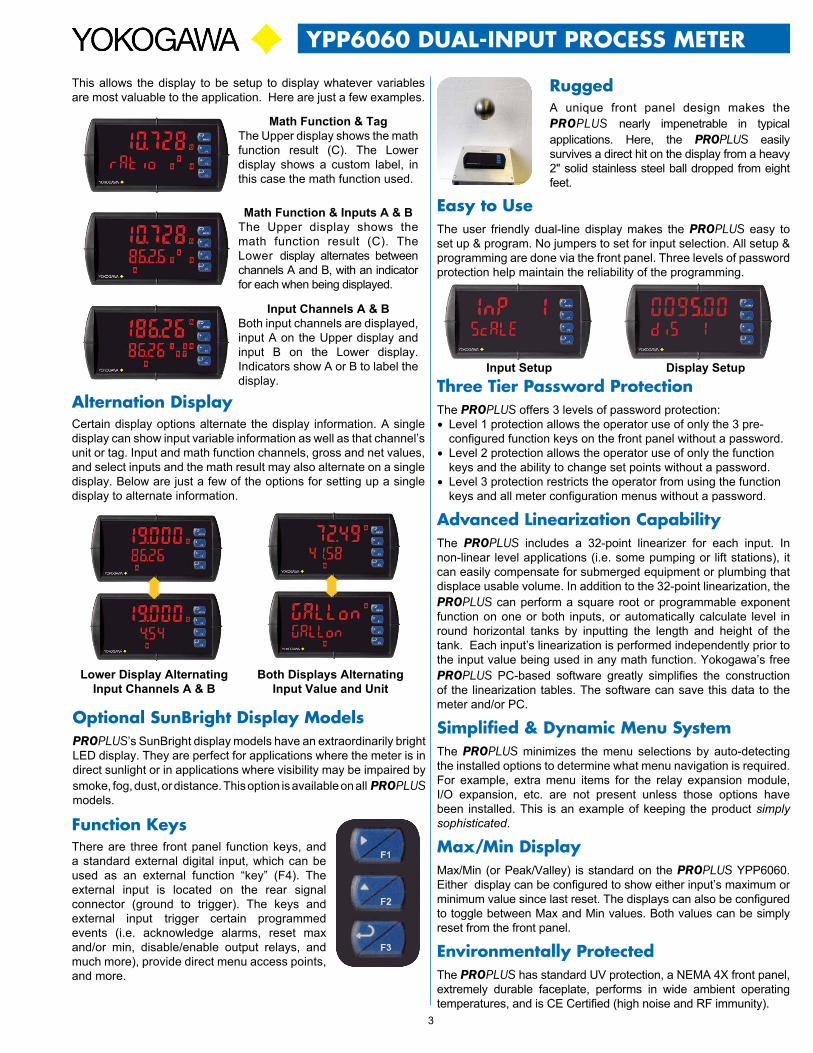
This allows the display to be setup to display whatever variables are most valuable to the application. Here are just a few examples.
Math Function & TagThe Upper display shows the math function result (C). The Lower display shows a custom label, in this case the math function used.
Alternation DisplayCertain display options alternate the display information. A single display can show input variable information as well as that channel’s unit or tag. Input and math function channels, gross and net values, and select inputs and the math result may also alternate on a single display. Below are just a few of the options for setting up a single display to alternate information.
Math Function & Inputs A & BThe Upper display shows the math function result (C). The Lower display alternates between channels A and B, with an indicator for each when being displayed.
Input Channels A & BBoth input channels are displayed, input A on the Upper display and input B on the Lower display. Indicators show A or B to label the display.
Lower Display Alternating Input Channels A & B
Both Displays Alternating Input Value and Unit

4
YPP6060 DUAL-INPUT PROCESS METER
Serial communications on the PROPLUS can be added anytime with external YPPA1232 (RS-232) or YPPA1485 (RS-485), or YPPA8008 (USB) communication adapters.
Free Modbus protocol with purchase of PROPLUS serial communications modules.
FIELD ExPANSION MODULESAdd functionality to the PROPLUS in the field with easy-to-install external expansion modules. Add RS-232 or RS-485 communications, I/O modules (up to 2), and 4-relay expansion module. The menu items for these modules do not appear until the module is connected, simplifying the basic menu. Relay and digital I/O modules are shown below with optional DIN rail mounting kit, P/N YPPA1002.
YPPA1044 I/O Expansion Module Four digital inputs and four digital outputs are available per expansion module. The PROPLUS meter will accept two of these modules. External digital inputs can function similarly to the front panel function keys. They can be configured to trigger certain events (i.e. acknowledge/reset alarms, reset max and/or min values, disable/enable all output relays, and hold current relay states), provide direct menu access point, or mimic front panel keys. The I/O module can be used to configure the PROPLUS remotely, in essence giving the user control of the four front panel push buttons. This feature is particularly useful if the meter is mounted inside an explosion-proof enclosure.
Digital outputs can be used to remotely monitor PROPLUS’s alarm relay output states, or the states of a variety of actions and functions executed by the meter.
YPPA1004 Relay Expansion ModuleAn external module containing four 3 A Form A (SPST) relays can be added to the PROPLUS at anytime. Removable screw terminal blocks accept 12 to 22 AWG wire.
PROPLUS SOFTwAREConfigure, monitor, and datalog a PROPLUS YPP6060 from a PC using PROPLUS Software (available for download at www.yokogawa-usa.com) and a serial adapter.
Mon
itor &
Dat
alog
DIgItal communIcatIons
Modbus® RTU Serial CommunicationsWith the purchase of a serial communication adapter, PROPLUS meters can communicate with any Modbus Master device using the ever-popular Modbus communications protocol that is included in every PROPLUS. This greatly increases the flexibility of the meter. Modbus provides much more capability than read PV and write set points. Below are some examples of other things that can be done with PROPLUS’s Modbus communications.
• Send a 6-character message to the lower display upon an event
• Convert a digital value to a 4-20 mA signal
• Remote user control (i.e. change set points, acknowledge alarms)
• Input a Modbus digital PV (in place of one analog input)
• Remote override of any, or all, relays and analog outputs
Meter CopyThe Copy feature is used to copy (or clone) all the settings from one PROPLUS meters to other PROPLUS meters in about 20 seconds! The Copy function is a standard feature on all meters. It does not require a communications adapter, only an optional cable assembly, P/N YPPA1200. See the ordering information for complete details.
Remote MessageModbus PV Input
YPPA1232 & YPPA1485, & YPPA8008 Communication Modules

5
YPP6060 DUAL-INPUT PROCESS METER
outputs
Relay OutputsThe PROPLUS has up to four 3 A Form C relays (SPDT) with multiple power loss fail-safe options. Each relay may be assigned to input channel A or B, or math result (C). Relays can be configured for proper protective action upon input loop break. Relay ON and OFF delay times are user adjustable. Up to eight front panel indicators show alarm and/or relay state. All relays can be configured for 0-100% deadband.
Relay Operation/ConfigurationThere are powerful relay functions that can be configured in the PROPLUS meter, including:• Automatic reset only (non-latching)• Automatic + manual reset at any time (non-latching)• Latching (manual reset only)• Latching with clear (manual reset only after alarm condition has cleared)• Pump alternation control (automatic reset only) • Sampling (activated for a user-specified time)• User selectable fail-safe operation• Relay action for loss (break) of 4-20 mA input signal• Time delay (on and off), independent for each relay• Manual control mode• Interlock relay mode
Analog Output The isolated analog retransmission signal can be configured to represent process input channel A or B, math result (C), max or min for channel A, B, or highest or lowest max or min of A and B, set points 1-8, Modbus input, or manual control mode. While the output is nominally 4-20 mA, the signal will accurately accommodate under- and over-ranges from 1 to 23 mA.
Manual Output ControlTake control of any output with this feature. All relays can be forced ON or OFF, and the 4-20 mA output signal can be set to any value within its range. When the relays and 4-20 mA output are controlled manually, an LED labeled “M” is turned on and the associated Alarm LEDs (1-8) flash every 10 seconds indicating that the meter is in manual control mode.
Isolated Transmitter Power SuppliesA powerful 24 V @ 200 mA power supply is a standard feature on the PROPLUS meter. It can be configured for 5, 10, or 24 V (default) by means of a simple internal jumper (see manual). An additional power supply (24 V @ 40 mA) is standard with the 4-20 mA output option.
Sampling Function (PV Triggered Timed Relay)The sampling function allows the operator to set a set point for a “sampling” relay. The relay can be assigned to input channels A or B, or the math result (C). When the PV reaches that set point, it will close that relay’s contacts for a preset period of time (0.1 to 5999.9 seconds). An example of its use may be for beer/ale fermentation. When the batch reaches a certain pH, the relay contacts would close and alert someone or automatically take a sample of the batch. This function can be used whenever a timed relay output closure is required when the PV reaches a certain set point.
Interlock Relay(s) This function allows a process to use one or more very low voltage input signals or simple switch contacts to control the state of one or more internal “interlock” relays. A violation (i.e. loss of input, open switch, or open circuit) forces one or more N/O interlock relay contacts to open. One input can be used in series with a number of interlock switches, or up to eight inputs can be required to force-on one (or more) internal interlock relays. Please see Application Note AN-1008 on our website for more information. Requires YPPA1044 Digital I/O module.
sIgnal Input conDItIonIngNon-linear input signals (i.e. weirs & flumes, differential pressure, etc.) can be linearized with the PROPLUS’s simple to use built-in signal input conditioning, such as: square-root extractor, exponential linearizer, horizontal round tank linearizer, or the PROPLUS powerful general purpose 32-point linearizer.
INPUT A4-20 mA signal
INPUT B
To second flow signal
123 3456 2 1
F3
F2
F1
MENU
INPUT A4-20 mA Outputfrom Level Transmitter
LevelTransmitter
Linearized4-20 mA outputfrom PROPLUS
INPUT B
To second tank
Loop-PoweredRemoteIndicator(Volume)
+
–
4-20 mA Loop powered by the PROVU meter
LoAlarm
HiAlarm
4-20 mA Out
Relay 1Relay 2
C
Weir Flow Calculated Using Exponential Signal Input Conditioning
Round Horizontal Tank Signal Input Conditioning
COMNO NC
4 36 5 2 1
+5V I1
1 2
115 VAC
NEUTLOAD
COMNO NC
InterlockContact
(Digital Input) ControlRelay
InterlockRelay

6
YPP6060 DUAL-INPUT PROCESS METER
1
2
3
4
At 4000 gallons, relay 3 turns off and the system returns to normal pump alternation control.
If the backup pump is not able to keep up, and the level reaches 7000 gallons, relay #4 transfers and starts the main pump as well.
With the Pump Alternation feature activated, the nexttime the level reaches 6000 gallons, relay #3 transfersand starts the backup pump.
F3
F2
F1
MENU
F3
F2
F1
MENU
F3
F2
F1
MENU
F3
F2
F1
MENU
OFF
ON
OFF
Relay #4 turns the main pump on at 6000 gallonsand turns it off at 1000 gallons.
2000
Input 1
Input 2
Control Relay 1&2
Input 2
Control Relay 1&2
Input 2
Control Relay 1&2
Input 2
Control Relay 1&2
2000
20004000
2000 4000
OFF
B
A
B
A
B
A
B
A
Relay 4 Relay 3
Input 1
Input 1
Input 1
Relay 4 Relay 3
Relay 4 Relay 3
Relay 4 Relay 3
Multi-Pump AlternationUp to 8 pumps can be alternated/sequenced.
connectIons
RI- I+
MA OUT13 2
POWER
+ -
M-LINK
COM NONO NC NC COM
RELAY4 RELAY34 36 5 2 1
COM NONO NC NC COM
RELAY2 RELAY14 36 5 2 1
1 2 3 4 5 6 7 8
21
4-20 mA Output
-+
Powered by PROPLUS
24 V
• Form C (SPDT) relays• Two isolated supplies available even on 12/24 VDC input power models • Removable terminal blocks• 2 or 4 relays + isolated 4-20 mA output option
• Universal 85-265 VAC or 12/24 VDC input power• Voltage or current inputs• No jumpers needed for V/mA input selection• M-Link for adding expansion modules
+ -2-Wire
4-20 mATransmitter (A)
INPUT SIGNAL
P- F4P+ COM V+3 41 2 5
mA+ COM V+ mA+7 86 9
2-Wire4-20 mA
Transmitter (B)
+ -
Ch-A Ch-B
Notes:1. Panel cutout required: 1.772" x 3.622" (45 mm x 92 mm)2. Panel thickness: 0.040 - 0.250" (1.0 mm - 6.4 mm)3. Mounting brackets lock in place for easy mounting4. Clearance: Allow 6" (152 mm) behind the panel
3.61"(92 mm)
4.17"(106 mm)
4.68"(119 mm)
1.76"(45 mm)
0.59"(15 mm)
4.77"(121 mm)
2.45"(62 mm)
(128 mm)5.05"
Side View Top View
6" (152 mm) Clearance
NO NCNCC NOCNO NCNCC NOC+ -R
OptionalConnectorsInstalled
DImensIons
NEMA 4x FIELD ENCLOSURES Thermoplastic NEMA 4X enclosures are constructed for either indoor or outdoor use.
YPPA2811Plastic Low-Cost
YPPA2812Plastic Low-Cost

7
YPP6060 DUAL-INPUT PROCESS METER
SPECIFICATIONSExcept where noted all specifications apply to operation at +25°C.
GeneralDisplay: Upper display: 0.60” (15 mm) high, red LEDs Lower display: 0.46” (12 mm) high, red LEDs 6 digits each (-99999 to 999999), with lead zero blankingDisplay Intensity: Eight user selectable intensity levels Display Update Rate: 5/second (200 ms)Overrange: Display flashes 999999Underrange: Display flashes -99999Display Assignment: The Upper and Lower displays may be assigned to process values for Channels A (Ch-A), B (Ch-B), or C (Ch-C), toggle between (Ch-A & Ch-B, Ch-A & Ch-C, Ch-B & Ch-C, and Ch-A, Ch-B, & Ch-C), toggle between Channel & units, show channel gross value (no tare) or toggle net (tare) and gross values, show relay set points, max & min values, or Modbus input. The second display may also be set to show engineering units or be off, with no display.Front Panel: NEMA 4X, IP65Programming Methods: Four front panel buttons, digital inputs, PC and PROPLUS software, Modbus registers, or cloning using Copy function.Noise filter: Programmable from 2 to 199 (0 will disable filter)Filter Bypass: Programmable from 0.1 to 99.9% of calibrated spanRecalibration: All ranges are calibrated at the factory. Recalibration is recommended at least every 12 months.Max/Min Display: Max (Peak) / min (Valley) readings reached by the process are stored until reset by the user or until power to the meter is cycled.Password: Three programmable passwords restrict modification of programmed settings. Pass 1: Allows use of function keys and digital inputs. Pass 2: Allows use of function keys, digital inputs and editing set/reset points. Pass 3: Restricts all programming, function keys, and digital inputs.Non-Volatile Memory: All programmed settings are stored in non-volatile memory for a minimum of ten years if power is lost.Power Options: 85-265 VAC 50/60 Hz, 90-265 VDC, 20 W max, or jumper selectable 12/24 VDC ±10%, 15 W max.Fuse: Required external fuse: UL Recognized, 5 A max, slow blow; up to 6 meters may share one 5 A fuse.Isolated Transmitter Power Supply: Terminals P+ & P-: 24 VDC ±5% @ 200 mA max (standard), (12/24 VDC powered models rated @ 100 mA max). 5 or 10 VDC @ 50 mA max, selectable with internal jumper J4.Normal Mode Rejection: Greater than 60 dB at 50/60 HzIsolation: 4 kV input/output-to-power line. 500 V input-to-output or output-to-P+ supply.Overvoltage Category: Installation Overvoltage Category II: Local level with smaller transient overvoltages than Installation Overvoltage Category III.Operating Temperature Range: -40 to 65°CStorage Temperature Range: -40 to 85°CRelative Humidity: 0 to 90% non-condensing.Connections: Removable screw terminal blocks accept 12 to 22 AWG wire, RJ45 for external relays, digital I/O, and serial communication adapters.Enclosure: 1/8 DIN, high impact plastic, UL 94V-0, color: blackMounting: 1/8 DIN panel cutout required: 3.622" x 1.772" (92 mm x 45 mm). Two panel mounting bracket assemblies are provided.Tightening Torque: Screw terminal connectors: 5 lb-in (0.56 Nm)Overall Dimensions: 4.68" x 2.45" x 5.64" (119 mm x 62 mm x 143 mm) (W x H x D)Weight: 9.5 oz (269 g)UL File Number: UL & c-UL Listed. E348677; 508 Industrial Control Equipment.Warranty: 3 years parts & labor
Dual Process InputInputs: Two inputs, each separately field selectable: 0-20, 4-20 mA, 10 V (0-5, 1-5, 0-10 V), Modbus PV (Slave)Channels: Channel A, Channel B, Channel C (Math channel)
Programmable Constants: Constant P (Adder): -99999 to 999999, default: 0.000; Constant F (Factor): 0.00001 to 999999, default: 1.000Math Functions:Name Function SettingAddition (A+B+P)*F Sunm
Difference (A-B+P)*F diF
Absolute diff. ((Abs(A-B))+P)*F diFAbS
Average (((A+B)/2)+P)*F AvG
Multiplication ((A*B)+P)*F nmulti
Divide ((A/B)+P)*F divide
Max of A or B ((AB-Hi)+P)*F Hi-Ab
Min of A or B ((AB-Lo)+P)*F Lo-Ab
Draw ((A/B)-1)*F drAuw
Weighted Avg. ((B-A)*F)+A uw avg
Ratio (A/B)*F ratio
Concentration (A/(A+B))*F Concen
Note: The F constant can be any value from 0.00001 to 999999. If the value is less than 1, it will have the same effect as a divider. For example, the average could also be derived by using (A+B)*F, where F = 0.500.Sequence of Operations for Input Programing: 1. Select Input for A and B2. Set up the engineering units for A, B, and C3. Set up decimal point for A, B, and C4. Scale A & B5. Set up the displays for A, B, or C6. Select the transfer function for A & B (e.g. Linear)7. Select Math function for Channel C8. Program constants for Factor (F) and Adder (P).9. Program cutoff values for A and BAccuracy: ±0.03% of calibrated span ±1 count, square root & programmable exponent accuracy range: 10-100% of calibrated spanTemperature Drift: 0.005% of calibrated span/°C max from 0 to 65°C ambient, 0.01% of calibrated span/°C max from -40 to 0°C ambientSignal Input Conditioning: Linear, square root, programmable exponent, or round horizontal tank volume calculation.Multi-Point Linearization: 2 to 32 points for PV or PV1. 2 to 8 points for PV2 (Dual-Scale Level feature)Programmable Exponent: 1.0001 to 2.9999Low-Flow Cutoff: 0-999999 (0 disables cutoff function)Decimal Point: Up to five decimal places or none: d.ddddd, dd.dddd, ddd.ddd, dddd.dd, ddddd.d, or dddddd.Calibration Range: 4-20 mA: minimum span input 1 & input 2: 0.15 mA. ±10 V: minimum span input 1 & 2: 0.10 V. An Error message will appear if input 1 and input 2 signals are too close together. Input Impedance: Voltage ranges: greater than 500 kΩ. Current ranges: 50 - 100 Ω (depending on resettable fuse impedance).Input Overload: Current input protected by resettable fuse, 30 VDC max. Fuse resets automatically after fault is removed.
RelaysRating: 2 or 4 SPDT (Form C) internal and/or 4 SPST (Form A) external; rated 3 A @ 30 VDC and 125/250 VAC resistive load; 1/14 HP (≈ 50 W) @ 125/250 VAC for inductive loads. Noise Suppression: Noise suppression is recommended for each relay contact switching inductive loads.Deadband: 0-100% of span, user programmableHigh or Low Alarm: User may program any alarm for high or low trip point. Unused alarm LEDs and relays may be disabled (turned off).Relay Operation: automatic (non-latching), latching (requires manual acknowledge), sampling (based on time), pump alternation control (2 to 8 relays), Off (disable unused relays and enable interlock feature, manual on/off control mode).Relay Reset: User selectable via front panel buttons or digital inputs.1. Automatic reset only (non-latching), when input passes the reset point. 2. Automatic + manual reset at any time (non-latching).

LDS6060YK_B 11/11
2 Dart Road • Newnan, Georgia 30265 770-253-7000 • 800-888-6400Fax: 770-251-2088 • www.yokogawa-usa.com
YPP6060 DUAL-INPUT PROCESS METER
ORDERING INFORMATION
PROPLUS YPP6060 • Standard Models85-265 VAC Model
12/24 VDC Model Options Installed
YPP6060-6R0 YPP6060-7R0 None
YPP6060-6R2 YPP6060-7R2 2 Relays
YPP6060-6R3 YPP6060-7R3 4-20 mA Output
YPP6060-6R4 YPP6060-7R4 4 Relays
YPP6060-6R5 YPP6060-7R5 2 Relays & 4-20 mA Output
YPP6060-6R7 YPP6060-7R7 4 Relays & 4-20 mA Output
Note: 24 V Transmitter power supply standard on all models.
PROPLUS YPP6060 • SunBright Display Models85-265 VAC Model
12/24 VDC Model Options Installed
YPP6060-6H0 YPP6060-7H0 None
YPP6060-6H2 YPP6060-7H2 2 Relays
YPP6060-6H3 YPP6060-7H3 4-20 mA Output
YPP6060-6H4 YPP6060-7H4 4 Relays
YPP6060-6H5 YPP6060-7H5 2 Relays & 4-20 mA Output
YPP6060-6H7 YPP6060-7H7 4 Relays & 4-20 mA Output
Note: 24 V Transmitter power supply standard on all models.
AccessoriesModel Description
YPPA1002 DIN Rail Mounting Kit for Two Expansion Modules
YPPA1004 4-Relay Expansion Module
YPPA1044 4 Digital Inputs & 4 Digital Outputs Module
YPPA1200 Meter Copy Cable
YPPA1232 RS-232 Serial Adapter
YPPA1485 RS-485 Serial Adapter
YPPA8008 USB-Serial Adapter
YPPA7485-I RS-232 to RS-422/485 Isolated Converter
YPPA7485-N RS-232 to RS-422/485 Non-Isolated Converter
YPPA8232-N USB to RS-232 Non-Isolated Converter
YPPA8485-I USB to RS-422/485 Isolated Converter
YPPA8485-N USB to RS-422/485 Non-Isolated Converter
YPPX6901 Suppressor (snubber): 0.01 μF/470 Ω, 250 VAC
DisclaimerThe information contained in this document is subject to change without notice. Yokogawa Corporation of America makes no representations or warranties with respect to the contents hereof, and specifically disclaims any implied warranties of merchantability or fitness for a particular purpose. ©2011 Yokogawa Corporation of America. All rights reserved
Your Local Distributor is:
Isolated 4-20 mA Transmitter OutputOutput Source: Process channel A, B, or C, max or min for channel A, B, or highest or lowest max or min of A and B, set points 1-8, Modbus input, or manual control modeScaling Range: 1.000 to 23.000 mA for any display rangeCalibration: Factory calibrated: 4.000 to 20.000 = 4-20 mA outputAnalog Output Programming: 23.000 mA maximum for all parameters: Overrange, underrange, max, min, and breakAccuracy: ± 0.1% of span ± 0.004 mATemperature Drift: 0.4 μA/°C max from 0 to 65°C ambient, 0.8 μA/°C max from -40 to 0°C ambient Note: Analog output drift is separate from input drift.Isolated Transmitter Power Supply: Terminals I+ & R: 24 VDC ± 5% @ 40 mA maximum, may be used to power the 4-20 mA output or other devices.External Loop Power Supply: 35 VDC maximumOutput Loop Resistance: Power supply Minimum Maximum 24 VDC 10 Ω 700 Ω 35 VDC (external) 100 Ω 1200 Ω
Digital I/O Expansion ModuleChannels: 4 digital inputs & 4 digital outputs per moduleSystem: Up to 2 modules for a total of 8 inputs & 8 outputsDigital Input Logic: High: 3 to 5 VDC Low: 0 to 1.25 VDCDigital Output Logic: High: 3.1 to 3.3 VDC Low: 0 to 0.4 VDCSource Current: 10 mA maximum Sink Current: 1.5 mA minimum+5 V Terminal: To be used as pull-up for digital inputs only.
4-Relay Expansion ModuleRelays: Four Form A (SPST) rated 3 A @ 30 VDC and 125/250 VAC resistive load; 1/14 HP (≈ 50 watts) @ 125/250 VAC for inductive loads.
3. Manual reset only, at any time (latching).4. Manual reset only after alarm condition has cleared (latching).Note: Front panel button or digital input may be assigned to acknowledge relays programmed for manual reset.Time Delay: 0 to 999.9 seconds, on & off relay time delays. Programmable and independent for each relay.Fail-Safe Operation: Programmable and independent for each relay. Note: Relay coil is energized in non-alarm condition. In case of power failure, relay will go to alarm state.Auto Initialization: When power is applied to the meter, relays will reflect the state of the input to the meter.
Serial CommunicationsProtocol: Modbus® RTUMeter Address/Slave ID: 1 - 247Baud Rate: 300 - 19,200 bpsTransmit Time Delay: Programmable between 0 and 199 msData: 8 bit (1 start bit, 1 or 2 stop bits)Parity: Even, odd, or none with 1 or 2 stop bitsByte-to-Byte Timeout: 0.01 - 2.54 secondsTurn Around Delay: Less than 2 ms (fixed)Note: Refer to the YPP6000/YPP7000 Modbus Register Tables located at www.yokogawa-usa.com for details.


![TrimarcSecurity.com ] - Active Directory Security · Azure AD Premium Password Protection (Public Preview) •On-prem Active Directory solution. •Microsoft Password Filter deployed](https://static.fdocuments.net/doc/165x107/5ec94a0f5022c321eb7833b3/-active-directory-security-azure-ad-premium-password-protection-public-preview.jpg)