Dual Fuel Gas / Light Oil Burners - Power Equipment Company
26
Installation, use and maintenance instructions Dual Fuel Gas / Light Oil Burners RLS 28 - 38 - 50 Low - High Operation C6505058
Transcript of Dual Fuel Gas / Light Oil Burners - Power Equipment Company

Installation, use and maintenance instructions
Dual Fuel Gas / Light Oil Burners
RLS 28 - 38 - 50
Low - High Operation
C6505058

2
CONTENTS
FUEL OIL / GAS
Technical data . . . . . . . . . . . . . . . . . . . . . . . . . . . . . . . . . . page 3Burner models . . . . . . . . . . . . . . . . . . . . . . . . . . . . . . . . . . . . . . . 3Accessories . . . . . . . . . . . . . . . . . . . . . . . . . . . . . . . . . . . . . . . . . 3Burner description . . . . . . . . . . . . . . . . . . . . . . . . . . . . . . . . . . . . 4Packaging - Weight. . . . . . . . . . . . . . . . . . . . . . . . . . . . . . . . . . . . 4Max. dimensions. . . . . . . . . . . . . . . . . . . . . . . . . . . . . . . . . . . . . . 4Standard equipment . . . . . . . . . . . . . . . . . . . . . . . . . . . . . . . . . . . 4Firing rates . . . . . . . . . . . . . . . . . . . . . . . . . . . . . . . . . . . . . . . . . . 5Minimum furnace dimensions. . . . . . . . . . . . . . . . . . . . . . . . . . . . 5Installation . . . . . . . . . . . . . . . . . . . . . . . . . . . . . . . . . . . . . . . . . . 6Boiler plate . . . . . . . . . . . . . . . . . . . . . . . . . . . . . . . . . . . . . . . . . . 6Blast tube length . . . . . . . . . . . . . . . . . . . . . . . . . . . . . . . . . . . . . 6Securing the burner to the boiler . . . . . . . . . . . . . . . . . . . . . . . . . 6
FUEL OIL
Choice of nozzles for 1st and 2nd stage . . . . . . . . . . . . . . . . . . . 6Nozzle assembly . . . . . . . . . . . . . . . . . . . . . . . . . . . . . . . . . . . . . 7Adjustments before first firing. . . . . . . . . . . . . . . . . . . . . . . . . . . . 7
FUEL OIL / GAS
Servomotor. . . . . . . . . . . . . . . . . . . . . . . . . . . . . . . . . . . . . . . . . . 8
FUEL OIL
Pump . . . . . . . . . . . . . . . . . . . . . . . . . . . . . . . . . . . . . . . . . . . . . . 8Fuel supply . . . . . . . . . . . . . . . . . . . . . . . . . . . . . . . . . . . . . . . . . . 9Hydraulic connections . . . . . . . . . . . . . . . . . . . . . . . . . . . . . . . . . 9Pump priming . . . . . . . . . . . . . . . . . . . . . . . . . . . . . . . . . . . . . . . . 9Burner calibration . . . . . . . . . . . . . . . . . . . . . . . . . . . . . . . . . . . . 10
GAS
Gas pressure . . . . . . . . . . . . . . . . . . . . . . . . . . . . . . . . . . . . . . . 11Gas piping . . . . . . . . . . . . . . . . . . . . . . . . . . . . . . . . . . . . . . . . . 12Adjustments before first firing. . . . . . . . . . . . . . . . . . . . . . . . . . . 13Burner starting . . . . . . . . . . . . . . . . . . . . . . . . . . . . . . . . . . . . . . 13Burner firing . . . . . . . . . . . . . . . . . . . . . . . . . . . . . . . . . . . . . . . . 13Burner calibration . . . . . . . . . . . . . . . . . . . . . . . . . . . . . . . . . . . . 14
FUEL OIL / GAS
Maintenance. . . . . . . . . . . . . . . . . . . . . . . . . . . . . . . . . . . . . . . . 16Hydraulic system layout . . . . . . . . . . . . . . . . . . . . . . . . . . . . . . . 17
ELECTRICAL
Factory wiring diagram - RLS 28-38 with burner mounted LFL . 18Factory wiring diagram - RLS 50 with burner mounted LFL. . . . 19Field wiring diagram - RLS 28-38-50 with burner mounted LFL 20Factory wiring diagram - RLS 28-38-50 with remote panel . . . . 21Appendix - Burner firing rates according to air density. . . . . . . . 22Flame signal measurement . . . . . . . . . . . . . . . . . . . . . . . . . . . . 23Siemens LFL control sequence of operations . . . . . . . . . . . . . . 23Siemens LFL control troubleshooting guide . . . . . . . . . . . . . . . 24Burner start up report. . . . . . . . . . . . . . . . . . . . . . . . . . . . . . . . . 25
WARNING
If you smell gas:
• Do not touch any electrical items.• Open all windows.• Close all gas supply valves.• Contact your local gas authority immediately.
Do not store flammable or hazardous materials in the vicinity of fuel burning appliances.
Improper installation, adjustment, alteration, service or main-tenance can cause property damage, personal injury or death. Refer to this manual for instructional or additional in-formation. Consult a certified installer, service representative or the gas supplier for further assistance.
Burner shall be installed in accordance with manufacturers requirements as outlined in this manual, local codes and au-thorities having juristiction.

3
TECHNICAL DATA
(1)
Reference conditions: Ambient temperature 68 °F (20°C) - Barometric pressure 394” WC - Altitude 329 ft.
(2)
Pressure at test point 7)(A)p.4 with zero pressure in the combustion chamber and maximum burner output.
(3)
Sound pressure measured in manufacturer’s combustion laboratory, with burner operating on test boiler and at maximum rated output.
(4)
Equivalent Btu values based on 1 USGPH = 140,000 Btu/hr.
Burner models designation:
Accessories
(optional):
• Kit for lengthening the combustion head
L =Standard lengthL1 =Length obtainable with the kitCOD. 3010264 L = 7
1/2
” L1 = 12
27/32
” • RLS 28COD. 3010265 L = 7
29/32
“ L1 = 13
7/32
” • RLS 38COD. 3010266 L = 8
1/2
” L1 = 13
13/16
” • RLS 50
• Kit for LPG operation -
Code
3010304:
The kit allows the RLS 28-38-50 burners to operate on LPG
.
•
Gas train according to UL Standards:
see page 12.
MODEL RLS 28 RLS 38 RLS 50
Output
(1)
Delivery
(1)
2nd stage MBtu/hr
(4)
616 - 1232 882 - 1666 1092 - 2198kW 181 - 361
4.4 - 8.8258 - 4886.3 - 11.9
320 - 6447.8 - 15.7GPH
min. 1st stage
MBtu/hr
(4)
378 434 546kW 111
2.71273.1
1603.9GPH
Fuel #2 Fuel oilNatural gas / Propane gas
Gas pressure at maximum delivery
(2),
Gas: Natural gas” WC 4.33 5.11 5.51
Operation low-highNozzles number 2Ambient temperature °F 32 - 104 (0 - 40 °C)Combustion air temperature °F max 140 (60 °C)Main power supply (+/- 10%) V/Ph/Hz 120/1/60 208-230/460/575/3/60Electric motors rpm 3400Fan motor
Fan motor capacitor
VW - HP
AµF
120370 - 0.5
5.245
120370 - 0.5
5.245
208 - 230 / 460 / 575550 - 0.75
3.2 - 1.6 - 1.3n/a
Pump motor
Pump motor capacitor
VW - HP
AµF
12090 - 0.12
0,812,5
Ignition transformer Oil V1 - V2I1 - I2
120 V - 2 x 5 kV3.7 A - 35 mA
Gas V1 - V2I1 - I2
120 V - 1 x 7 kV1.6 A - 23 mA
Pump Delivery (at 174 PSI)Pressure rangeFuel temperature
GPHPSI
° F max
21.558 - 261
140 (60 °C)Electrical power consumption W max 760 760 910Electrical protection NEMA 1Noise Levels
(3)
dBA 68 70 72
Model Code Voltage Flame safeguard
RLS 28C9531000
(3483270)
C9631000
(3483272)120/1/60120/1/60
Burner mountedRemote panel
RLS 38C9532000
(3484170)
C9632000
(3484172)120/1/60120/1/60
Burner mountedRemote panel
RLS 50
C9533000
(3484670)
C9533001
(3484670)
C9633000
(3484672)
C9633001
(3484672)
208-230/460/3/60575/3/60
208-230/460/3/60575/3/60
Burner mountedBurner mountedRemote panelRemote panel
Important:
The installer is responsible for the supply and installation of any required safety device(s) not indicated in this manual.

4
BURNER DESCRIPTION (A)
1 Combustion head2 Ignition electrodes3 Screw for combustion head adjustment4 Sleeve5 Low air pressure switch
(differential operating type)6 Air pressure test point7 Gas pressure test point and head fixing screw8 Screw securing fan to sleeve9 Slide bars for opening the burner and inspecting the
combustion head10 Pump11 Safety solenoid valve12 Low and high fire oil valves13 Servomotor14 UV scanner15 Plate with four hole knock-outs for flexible hoses and
electrical cable routing.16 Air inlet to fan17 Gas input connection18 Boiler mounting flange19 Flame stability disk20 Flame inspection window21 Oil / gas selector switch22 Fan motor contactor and thermal overload with reset
button (RLS 50 three-phase)23 Flame safeguard with lock-out pilot light and lock-out
reset button24 Power switch for different operations:
automatic - manual - offButton for:power increase - power reduction
25 Burner terminal strip26 Low oil pressure switch27 Pump motor
Two types of burner failure may occur:
• Flame safeguard lock-out
: if the flame relay 23)(A) pushbutton lights up, it indi-cates that the burner is in lock-out. To reset, press the pushbutton.
• Motor trip
(RLS 50 three-phase):Release by pressing the pushbutton on the thermaloverload 22)(A).
PACKAGING - WEIGHT (B)
- Approximate measure-ments• The burners are shipped in cardboard boxes with the
maximum dimensions shown in table (B).• The weight of the burner complete with packaging is
indicated in Table (B).
MAX. DIMENSIONS (C)
-
Approximate measure-mentsThe maximum dimensions of the burners are given in(C).Note that if you need to examine the combustion head,the burner must be pulled backward on the slide bars andturned upward.The maximum dimension of the burner, without the cover,when open is given by measurement H.
STANDARD EQUIPMENT
1 - Gas train flange1 - Flange gasket4 - Flange fixing screws4 - Screws to secure the burner flange to the boiler:
3/8
W x 1”1 - Adaptor G
1/8
“ /
1/8
“ NPT1 - Instruction booklet1 - Spare parts list
(A)
inch A B C lbs
RLS 28 3931/32“ 2413/16“ 1911/16“ 95
RLS 38 3931/32“ 2413/16“ 1911/16“ 99
RLS 50 3931/32“ 2413/16“ 1911/16“ 101D88
(B)
RLS A B C D E F G H I L M
28 1823/32“ 1821/32“ 2213/16“ 71/2“ 51/2“ 1327/32“ 67/16“ 317/8“ 41/4“ 65/8“ 11/2”
38 1823/32“ 1821/32“ 2213/16“ 729/32“ 531/32“ 1327/32“ 67/16“ 317/8“ 41/4“ 65/8“ 11/2”
50 1823/32“ 1821/32“ 2213/16“ 81/2“ 531/32“ 1327/32“ 67/16“ 317/8“ 41/4“ 65/8“ 11/2”
(C)
D2534
D2536
D1118
D495

5
FIRING RATES (A)
The RLS 28 - 38 - 50 Model burners can work in twoways: low and high fire.
MAXIMUM OUTPUT
must be selected in area A.
MINIMUM OUTPUT
must not be lower than the mini-mum limit shown in the diagram:
RLS 28 = 378 MBtu/hr = 2.7 GPHRLS 38 = 434 MBtu/hr = 3.1 GPHRLS 50 = 546 MBtu/hr = 3.9 GPH
Important:
The firing rate area values have been obtained consider-ing an ambient temperature of 68 °F (20°C), and anatmospheric pressure of 394” WC and with the combus-tion head adjusted as shown on page 7.
Note:
The FIRING RATE areas given in figure (A) have beenreduced by 10% with respect to the maximum range thatcan be reached.
Consult Appendix on page 22 for operation at differentambient temperatures and/or altitudes.
MINIMUM FURNACE DIMENSIONS (B)
The firing rates were set in relation to certified test boil-ers. Figure (B) indicates the diameter and length of the testcombustion chamber.
Example:
output 1388 MBtu/hr:diameter 20 inch - length 4.9 ft.
(A)
RLS 28
RLS 38
RLS 50
Com
bust
ion
cham
ber
pres
sure
“WC
C
ombu
stio
n ch
ambe
r pr
essu
re“W
C
Com
bust
ion
cham
ber
pres
sure
“WC
D2537
(B) D2918
Leng
th (
ft)F
urna
ce d
imen
sion
s
Diameter (inches)

6
INSTALLATION
BOILER PLATE (A)
Drill the combustion chamber mounting plate as shown in(A). The position of the threaded holes can be markedusing the head gasket supplied with the burner.
BLAST TUBE LENGTH (B)
The length of the blast tube must be selected accordingto the indications provided by the manufacturer of theboiler, and it must be greater than the thickness of theboiler door complete with its insulation. The range oflengths available, L (inch), is as follows
Blast tube 10): RLS 28 RLS 38 RLS 50• short 7
1/2
“ 7
29/32
“ 8
1/2
“• long 12
27/32
“ 13
7/32
“ 13
13/16
“
For boilers with front flue passes 13) or flame inversionchambers, protective insulation 11) must be inserted be-tween the boiler refractory 12) and the blast tube 10).This protective insulation must not compromise the ex-traction of the blast tube.For boilers having a water-cooled front the insulation11)-12)(B) is not required unless it is required by theboiler manufacturer.
SECURING THE BURNER TO THE BOILER (B)
Detach the combustion head from the burner, fig. (B):- disconnect the oil pipes by unscrewing the two con-
nectors 4).- remove screw 14) and withdraw the cover 15).- remove the screws 2) from the slide bars 3).- remove screw 1) and pull the burner back on slide bars
3) by about 4”. Disconnect the electrode wires and then pull the burn-er completely off the slide bars, after removing the splitpin from the slide bar 3).
Secure the flange 9)(B) to the boiler plate, inserting thegasket 6)(B). Use the 4 screws, also supplied with theunit, after first protecting the thread with an anti-lockingproduct. The seal between burner and boiler must be airtight.
CHOICE OF NOZZLES FOR 1ST AND 2ND STAGEBoth nozzles must be chosen from among those listed intable (C).The first nozzle determines the delivery of the burner atlow fire.The second nozzle works together with the 1st nozzle todetermine the delivery of the burner at high fire.The deliveries at low and high fire must be containedwithin the value range indicated on page 3.Use nozzles with a 60° spray angle at the recommendedpressure of 174 PSI.The two nozzles usually have equaldeliveries.
Example with the RLS 28 ModelBoiler output = 921 MBtu/hr @ efficiency 80 %Output required by the burner = 921 / 0.8 = 1151 MBtu/hr 1151 / 2 = 576 MBtu/hr (4.0 USGPH) per nozzletherefore, two equal, 60°, 174 PSI nozzles arerequired:1° = 4.00 GPH with 2° = 4.00 GPH,or the following two different nozzles:1° = 4.50 GPH with 2° = 3.50 GPH,or:1° = 3.50 GPH with 2° = 4.50 GPH.
(C)
inch A B C
RLS 28 69/32“ 813/16“ 3/8 W
RLS 38 69/32“ 813/16“ 3/8 W
RLS 50 69/32“ 813/16“ 3/8 W
D455(A)
D2538
(B)
NOZZLEGPH
GPH MBTU/h
145 PSI 174 PSI 203 PSI 174 PSI
RLS 28
2.002.252.503.003.50
2.472.753.073.684.32
2.723.043.394.074.74
2.953.333.684.425.16
381426475570664
RLS 38
2.503.003.504.004.505.00
3.073.684.324.935.546.15
3.394.074.745.446.126.79
3.684.425.165.896.637.36
475570664762857951
RLS 50
3.003.504.004.505.005.506.00
3.684.324.935.546.156.767.40
4.074.745.446.126.797.468.17
4.425.165.896.637.368.108.87
570664762857951
10441144
60°
(D) D1122
D339

7
NOZZLE ASSEMBLYRemove screw 1)(D)p.6 and extract the internal part2)(D)p.6 Install two nozzles with the box wrench 1)(A),after having removed the plastic plugs 2)(A), fitting thewrench through the central hole in the flame stabilitydisk or loosen screws 1)(B), remove disk 2)(B) andreplace the nozzles using the wrench 3)(B).
Do not use any sealing products such as gaskets, seal-ing compound, or tape. Be careful to avoid damaging thenozzle sealing seat. The nozzles must be screwed intoplace tightly but carefully.The nozzle for low fire operation is the one underneaththe firing electrodes fig. (C).
Make sure that the electrodes are positioned as shownin figure (C).Refit the burner 4)(F) to the slide bars 3) at approximately4” from the sleeve 5) - burner positioned as shown in fig.(B)p. 6 - insert the ignition electrode cables and thenslide the burner up to the sleeve so that it is positioned asshown in fig. (F).Refit screws 2)(F) on slide bars 3).Secure the burner to the sleeve by tightening screw 1)and then refit the split pin into one of two slide bars 3).Connect the oil pipes again by screwing on the two con-nectors 4)(B)p.6.
ImportantWhen fitting the burner on the two slide bars, it is advis-able to gently draw out the high tension cables until theyare slightly stretched.
ADJUSTMENTS BEFORE FIRST FIRING(light-oil operation)
• Combustion head settingThe setting of the combustion head depends exclu-sively on the delivery of the burner at high fire. Turnscrew 5)(D) until the notch shown in diagram (E) islevel with the front surface of flange 6)(D).
Example burner RLS 38:High fire burner delivery = 9.6 GPH.If diagram (E) is consulted it is clear that for this deliv-ery, the combustion head must be adjusted usingnotch 4, as shown in fig. (D).
• Pump adjustmentNo settings are required for the pump, which is set to174 PSI by the manufacturer. This pressure must bechecked and adjusted (if required) after the burnerhas been ignited.The only operation required in this phase is the appli-cation of a pressure gauge on the appropriate pumpconnection.
• Fan damper adjustmentThe first time the burner is fired leave the factory set-ting unchanged for both low and high fire operation.
(A)
D1146 D1147
D2539
SETTING THE COMBUSTION HEAD
N°
Not
ches
Burner output in 2nd stage operation
D2540
D2541
(E)
D1149
(C)
(B)
(D)
(F)

8
SERVOMOTOR (A)The servomotor adjusts the air damper.The servomotor rotates through 90° in 25 seconds.Do not alter (for the time-being) the factory setting.
Blue camSets the position of the air damper during low fire opera-tion.
Red camSets the position of the air damper during high fire oper-ation.
Orange camEstablishes when the high fire gas or fuel oil valve opens. It must always operate (just) before the red cam and afterthe blue cam.
PUMP (B)1 - Suction 1/4” NPT2 - Return 1/4” NPT3 - Pressure gauge attachment G 1/8”4 - Vacuum gauge attachment G 1/8”5 - Pressure regulator
A - Min. delivery rate at 174 PSI pressureB - Delivery pressure rangeC - Max. suction pressureD - Viscosity rangeE - Max fuel oil temperatureF - Max. suction and return pressureG - Pressure calibration in the factoryH - Filter mesh width
(A)
(B)
BLUE CAM
RED CAM
ORANGE CAM
D2522
PUMPSUNTEC AL 65
AL 65
ABCDEFGH
GPHPSIPSIcSt
°F - °CPSIPSIinch
21.558 - 261
6.52 - 12
140 - 6029
1740.006
D2542
RESET

9
FUEL SUPPLY (A)The burner is equipped with a self-priming pump whichis capable of feeding itself within the limits listed in thetable at the side.The tank higher than the burner AThe distance “P” must not exceed 33 ft in order to avoidsubjecting the pump's seal to excessive strain; the dis-tance "V" must not exceed 13 ft in order to permit pumpself-priming even when the tank is almost completelyempty.The tank lower than the burner BPump suction values higher than 6.5 PSI must not be ex-ceeded because at higher levels gas is released from thefuel, the pump starts making noise and its working life-span decreases.It is good practice to ensure that the return and suctionlines enter the burner from the same height; in this wayit will be more improbable that the suction line fails toprime or stops priming.
KeyH = Pump/Foot valve height differenceL = Piping lengthØ = Inside pipe diameter1 = Burner2 = Pump3 = Filter4 = Manual on/off valve5 = Suction line6 = Foot valve7 = Return line
HYDRAULIC CONNECTIONS (B)The pumps are equipped with a by-pass that connectsreturn line and suction line. The pumps are installed onthe burner with the by-pass closed by screw 6), see dia-gram page 17.It is therefore necessary to connect both hoses to thepump.The pump seal will be damaged immediately if it is runwith the return line closed and the by-pass screw insert-ed.Remove the plugs from the suction and return connec-tions of the pump.Insert the hose connectors into the connections andscrew them down.Take care that the hoses are not stretched or twisted dur-ing installation.Route the hoses through the holes in the plate, prefera-bly using those on the right side, fig.(B): unscrew thescrews 1), now divide the insert piece into its two parts 2)and 3) and remove the thin plug blocking the two passag-es 4). Install the hoses where they cannot be stepped onor come into contact with hot surfaces of the boiler andwhere they do not hamper the opening of the burner.Now connect the other end of the hoses to the suctionand return lines.
PUMP PRIMING- Before starting the burner, make sure that the tank
return line is not clogged. Obstructions in the linecould cause the pump seal located on the pumpshaft to break. (The pump leaves the factory with theby-pass closed).
- Also check to make sure that the valves located on thesuction line are open and that there is sufficient fuel inthe tank.
- For self-priming to take place, one of the screws 3) ofthe pump, see fig.(B) page 8, must be loosened in or-der to bleed off the air contained in the suction line
(A)
(B)
+ H- Hft
L ftØ
inch
5/16” 3/8” 1/2”
+ 13+ 10+ 6.6+ 3.3+ 1.6
11599866963
296263227194174
500500500428391
0 56 158 355
- 1.5- 3.3- 6.6- 10- 13
49433013-
141122895320
31928321113866
1
2
37
5
6
6
7 5
4
A
B
+ H
- H
V
P
10 c
m
D2543
D2544

10
- Start the burner by closing the control circuit, withswitch 1)(A) in the "MAN" position and with switch21)(A)p.4 in the "OIL" position.
- The pump is primed when the fuel oil starts coming outof the screw 3)(B)p.8. Stop the burner: switch 1)(A) setto "OFF" and tighten the screw 3).
The time required for this operation depends upon the di-ameter and length of the suction tubing. If the pump failsto prime at the first starting of the burner and the burnerlocks out, reset the burner, and then repeat the startingoperation.Do not illuminate the UV scanner cell or the burner willlock out.
BURNER CALIBRATION (light-oil operation)
NoteIt is advisable to first set the burner for operation on oil
and then for gas.
• FIRINGSet switch 1)(A) to "MAN".During the first firing, and the change from low to highfire, there is a momentary lowering of the fuel pressurecaused by the filling of the high fire nozzle tubing. Thislowering of the fuel pressure can cause the burner tolock-out.
• OPERATIONThe optimum calibration of the burner requires an analy-sis of the flue gases at the boiler outlet and adjustmentsat the following points:
Low and high fire nozzlesSee the information listed on page 6.
Combustion headThe adjustment of the combustion head already carriedout (page 7) need not be altered unless the high fireinput of the burner is changed.
Pump pressure174 PSI: this is the pressure calibrated in the factorywhich is usually sufficient for most purposes. Some-times, this pressure must be adjusted to:145 PSI in order to reduce fuel delivery. This adjustmentis possible only if the surrounding temperature remainsabove 0°C;203 PSI in order to increase fuel delivery or to ensure fir-ings even at temperatures of less than 0°C.In order to adjust pump pressure, use the screw5)(B)p.8.
Low fire fan air damperKeep the burner operating at low fire. The fan airdamper is adjusted by moving the blue cam of the ser-vomotor, see page 8.
High fire fan air damperPress switch 2)(A) “increase output” and keep it presseduntil the high fire position. The fan air damper is adjustedby moving the red cam of the servomotor, see page 8.
WARNINGTurn burner off prior to switching fuels
(A)
1 2
D791

11
GAS PRESSUREThe adjacent tables show minimum pressure losses atcombustion head depending on the burner output athigh fire.
Gas pressure measured at test point 1)(B), with:• Combustion chamber at 0” WC• Burner operating at high fire• Natural gas
Calculate the approximate high fire output of the burneras follows:- subtract the combustion chamber pressure from the
gas pressure measured at test point 1)(B).- Find the nearest pressure value to your result in the
table for the burner in question.- Read off the corresponding output on the left.
Example - RLS 28• High fire operation• Natural gas• Gas pressure at test point 1)(B) = 3.66” WC• Pressure in combustion chamber = 0.79” WC
3.66 - 0.79 = 2.87” WCA high fire ouput of 796 MBtu/hr shown in table RLS 28corresponds to 2.87” WC pressure, natural gas.This value serves as a rough guide, the effective deliverymust be measured at the gas meter.
To calculate the required gas pressure at test point1)(B), set the output required from the burner in high fireoperation:- find the nearest output value in the table for the burner
in question.- Read off the pressure at test point 1)(B).- Add this value to the estimated pressure in the com-
bustion chamber.
Example - RLS 28• Required burner output in high fire operation:
796 MBtu/hr• Natural gas • Gas pressure at burner output of 796 MBtu/hr, taken
from table RLS 28, natural gas = 2.87” WC• Pressure in combustion chamber = 0.79” WC
2.87 + 0.79 = 3.66” WCpressure required at test point 1)(B).
(A)
RLS 28 ∆p (“ WC)
RLS 38 ∆p (“ WC)
RLS 50 ∆p (“ WC)
MBtu/hr Natural gas
616700796890985
107911741232
2.562.682.873.153.433.784.094.33
MBtu/hr Natural gas
882985
109812121325144015531666
3.463.583.703.864.094.374.655.11
MBtu/hr Natural gas
10921250140115531704185620072198
3.944.024.134.254.454.615.005.51
D2545
(B)
12
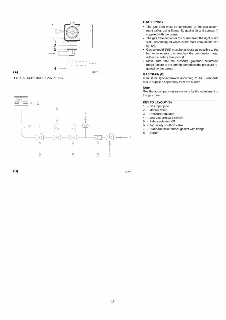
GAS PIPING• The gas train must be connected to the gas attach-
ment 1)(A), using flange 2), gasket 3) and screws 4)supplied with the burner.
• The gas train can enter the burner from the right or leftside, depending on which is the most convenient, seefig. (A).
• Gas solenoid 6)(B) must be as close as possible to theburner to ensure gas reaches the combustion headwithin the safety time period.
• Make sure that the pressure governor calibrationrange (colour of the spring) comprises the pressure re-quired by the burner.
GAS TRAIN (B)It must be type-approved according to UL Standardsand is supplied separately from the burner.
NoteSee the accompanying instructions for the adjustment ofthe gas train.
KEY TO LAYOUT (B)1 - Gas input pipe2 - Manual valve3 - Pressure regulator4 - Low gas pressure switch5 - Safety solenoid VS6 - 2nd safety shutt-off valve7 - Standard issue burner gasket with flange8 - Burner
(A)
(B)
D1137
D2546
TYPICAL SCHEMATIC GAS PIPING

13
ADJUSTMENTS BEFORE FIRST FIRING (gas operation)Adjustment of the combustion head has been illustratedon page 7. In addition, the following adjustments must also bemade:- open manual valves down stream and up stream from
the gas train.- Adjust the minimum gas pressure switch to the start of
the scale (A).- Adjust the air pressure switch to the zero position of
the scale (B).- Purge the air from the gas line.
Fit a U-type manometer (C) to the gas pressure testpoint on the sleeve.The manometer readings are used to calculate thehigh fire burner firing rate using the tables on page 11.
Before starting up the burner it is good practice to adjustthe gas train so that ignition takes place in conditions ofmaximum safety, i.e. with gas delivery at the minimum.
BURNER STARTING (gas operation)
NOTE: it is advisable to first set the burner to operate on
oil and then on gas.
Close the control circuit and set switch 1)(C) to "MAN"position.
BURNER FIRING (gas operation)Having completed the checks indicated in the previousheading, the burner should fire. If the motor starts but theflame does not appear and the flame relay goes intolock-out, reset and wait for a new firing attempt.If firing is still not achieved, it may be that gas is notreaching the combustion head within the safety time pe-riod.In this case increase gas firing delivery.The arrival of gas at the sleeve is indicated by the U-typemanometer (C).Once the burner has fired, proceed with calibration.
WARNINGTurn burner off prior to switching fuels
(A)
(B)
LOW GAS PRESSURE SWITCH AIR PRESSURE SWITCH
D2549
(C)
1 2
D791
D2547 D2548

14
BURNER CALIBRATION (gas operation)The optimum calibration of the burner requires an analy-sis of the flue gases at the boiler outlet.
Adjust successively:1 - High fire burner output2 - Low fire burner output3 - Air pressure switch4 - Minimum gas pressure switch
1 - HIGH FIRE OUTPUTHigh fire output of the burner must be set within the fir-ing rate range shown on page 5.Press switch 2)(A) “output increase”: the servomotor willopen the air damper at the previously set value for oiland will control the opening of the high fire gas valve.Gas calibrationAdjust gas delivery to the amount of air at this position.- If delivery needs to be reduced, diminish outlet gas
pressure and, if it is already very low, slightly closehigh fire adjustment valve.( if installed)
- If delivery needs to be increased, increase outlet gaspressure.
2 - LOW FIRE OUTPUTBurner power at low fire operation must be selected with-in the firing rate range shown on page 5.Press switch 2)(A) “output decrease” and keep it presseduntil the low fire position is reached: the servomotor willclose the air damper at the previously set value for oiland will control the opening of the low fire gas valve.Adjusting gas deliveryAdjust gas delivery to the amount of air by adjusting thelow fire gas valve VR1.
(A)
1 2
D791

15
3 - AIR PRESSURE SWITCH (A) - CO CHECKAdjust the air pressure switch after having performed allother burner adjustments with the air pressure switch setto the start of the scale (A).With the burner operating in low fire, increase adjustmentpressure by slowly turning the relative dial clockwise untilthe burner locks out.Then turn the dial anti-clockwise by about 20% of the setpoint and repeat burner starting to ensure it is correct.If the burner locks out again, turn the dial anti-clockwisea little bit more.
Attention:As a rule, the air pressure switch must block the forma-tion of CO.To check this, insert a combustion analyser into thechimney, slowly close the fan suction inlet (for examplewith cardboard) and check that the burner locks out,before the CO in the fumes exceeds 400 ppm.
The air pressure switch may operate in "differential"operation in two pipe system. If a negative pressure inthe combustion chamber during pre-purging preventsthe air pressure switch from switching, switching may beobtained by fitting a second pipe between the air pres-sure switch and the suction inlet of the fan. In this waythe air pressure switch operates as adifferential pres-sure switch.
4 - LOW GAS PRESSURE SWITCH (B)Adjust the low gas pressure switch after having per-formed all the other burner adjustments with the pressureswitch set at the start of the scale (B).With the burner operating at high fire, increase adjust-ment pressure by slowly turning the relative dial clock-wise until the burner locks out.Then turn the dial anti-clockwise by 0.8” WC and repeatburner starting to ensure it is uniform.If the burner locks out again, turn the dial anti-clockwiseagain by 0.4” WC.
(A)
AIR PRESSURE SWITCH
LOW GAS PRESSURE SWITCH
(B)
D2548
D2547

16
MAINTENANCE
CombustionThe optimum calibration of the burner requires an analy-sis of the flue gases. Significant differences with respectto the previous measurements indicate the points wheremore care should be exercised during maintenance.
Gas leaksMake sure that there are no gas leaks on the pipeworkbetween the gas meter and the burner.
Flame inspection windowClean the flame inspection window (A).
Combustion headOpen the burner and make sure that all components ofthe combustion head are in good condition, notdeformed by the high temperatures, free of impuritiesfrom the surroundings and correctly positioned. If indoubt, disassemble the elbow fitting 7)(C).
Nozzles (fuel oil)Do not clean the nozzle orifices. The nozzle filters however may be cleaned or replacedas required.Replace the nozzles every 2-3 years or whenever neces-sary.Combustion must be checked after the nozzles havebeen changed.
UV scanner Clean the glass cover from any dust that may haveaccumulated. The UV scanner 1)(B) is held in positionby a pressure fit and can therefore be removed by pull-ing it outward .
Flexible hoses (fuel oil)Check to make sure that the flexible hoses are still ingood condition and that they are not crushed or other-wise deformed.
BurnerCheck for excess wear or loose screws. Also make surethat the screws securing the electrical leads in the burnerconnections are fully tightened.Clean the outside of the burner.
CombustionAdjust the burner if the combustion values found at thebeginning of the operation do not comply with the regu-lations in force, or do not correspond to good combus-tion. Record the new combustion values; they will beuseful for subsequent comparison.
TO OPEN THE BURNER (C):- switch off the electrical power.- Remove screws 1) and withdraw cover 2).- Disconnect the light-oil pipes 7).- Remove screw 5), the split pin 9) and pull the burner
back by about 4” on the slide bars 6). Disconnect theelectrode leads and then pull the burner fully back.
- Tilt the burner as shown in the figure and fit the splitpin 9) into one of the slide bar holes so that the burnerremains in position
Now extract the internal part 7) after having removed thescrew 8).
TO CLOSE THE BURNER (C):remove the split pin 9) and push the burner until it isabout 4” from the sleeve. Re-connect the leads andslide the burner in until it comes to a stop. Refit screw 5),the split pin 9) and pull the leads gently out until they areslightly stretched. Reconnect the light-oil pipes.
(A)
FLAME INSPECTION WINDOW
D484
UV SCANNER
D1140
(B)
OPENING THE BURNER
D2550(C)

17
HYDRAULIC SYSTEM LAYOUT (A)1 Pump suction2 Filter3 Pump4 Pressure regulator5 Return pipe6 By-pass screw7 Pump return8 Safety solenoid9 Low fire valve10 High fire valve11 FilterM Pressure gaugeP Low oil pressure switchV Vacuum gauge
OIL PRESSURE SWITCHThe oil pressure switch 26)(A) page 4 is factory set to145 PSI (10 bar). If the oil pressure goes below thisvalue, the pressure switch stops the burner.
COMBUSTION CHECKSCO2It is better to set the burner with CO2 not higer than 10%(with natural gas). In this way avoiding a loss of calibra-tion setting (for example draft variation) that could causecombustion with little air and the production of CO.COIt must be not higher than 400 PPM.
(A)
D2596
P

18
(A)
Factory Wiring Diagram RLS 28 - 38With burner mounted Siemens LFL control
Burners RLS 28 - 38
Key to layout (A) C1 - Fan motor capacitorC2 - Pump motor capacitorCMV - Motor contactorK1 - RelayDA - LFL Control boxS1 - Switch for following operations:
MAN = manualAUT = automaticOFF
S2 - Button for:- = power reduction+ = power increaser
S3 - OIL/GAS selector MA - Auxiliary terminal stripMB - Burner terminal stripMV - Fan motorMP - Pump motorPA - Air pressure switchPO - Oil pressure switchRT - Thermal overloadSM - ServomotorTA - Ignition transformerTB - Burner groundUV - UV scannerV1 - Low fire oil valveV2 - High fire oil valveVS - Safety oil valve
D2295
D2879
Continuous fan operation Change the wire connection from terminal 6 to terminal 1, move the jumper from
A2 of of the motor contactor to terminal 6 of the control box, as indicated below.terminals 12-13 to terminals 4-12 and change the K1 - 9 wire connection from terminal

19
(A)
Factory Wiring Diagram RLS 50With burner mounted Siemens LFL control
Burners RLS 50
Key to layout (A) C1 - Fan motor capacitorC2 - Pump motor capacitorCMV - Motor contactorK1 - RelayDA - LFL Control boxS1 - Switch for following operations:
MAN = manualAUT = automaticOFF
S2 - Button for:- = power reduction+ = power increaser
S3 - OIL/GAS selector MA - Auxiliary terminal stripMB - Burner terminal stripMV - Fan motorMP - Pump motorPA - Air pressure switchPO - Oil pressure switchRT - Thermal overloadSM - ServomotorTA - Ignition transformerTB - Burner groundUV - UV scannerV1 - Low fire oil valveV2 - High fire oil valveVS - Safety oil valve
D2296
D2880
Continuous fan operation Change the wire connection from terminal 6 to terminal 1, move the jumper from
A2 of of the motor contactor to terminal 6 of the control box, as indicated below.terminals 12-13 to terminals 4-12 and change the K1 - 9 wire connection from terminal

20
(C)
ELECTRICAL CONNECTIONSUse flexible cables according to local Regulations.
LAYOUT (A) - The RLS 28 - RLS 38 Models
LAYOUT (B) - The RLS 50 Model
Fuses and wire size layout (A) -(B), see table (C).Wire size when not indicated: AWG18
Key to layouts (A) - (B)H1 - Remote lock-out signalH2 - Low fire signalH3 - High signalH4 - Power on signalH5 - Permission okIN - Burner manual stop switchPG - Low gas pressure switchPS - Remote lock-out resetMB - Burner terminal stripOCR - High-low control.
If the burner is to be set up for single stage operation installjumper between terminals T6 and T8.
OC - Operating control.HL - High limitY11 - Low fire gas valveY12 - High fire gas valveY10 - Safety gas valve
NOTESThe setting of thermal overload must correspond to the motor amper-age on of the burner.
Model RLS 50 three-phase, leaves the factory preset for 460 V powersupply. If 208-230 V power supply is uùsed, change the fan motorconnection from star to delta and change the setting of the thermaloverload as well.
The RLS 28-38-50 burners have been type- approved for intermittentoperation. This means they should compulsorily be stopped at leastonce every 24 hours to enable the flame safeguard to check its ownefficiency at start-up. Burner halts are normally provided for automat-ically by the boiler load control system.If this is not the case, a time switch should be fitted in series to IN toprovide for burner shut-down at least once every 24 hours.
Field Wiring DiagramRLS 50 with burner mounted Siemens LFL control
Field Wiring DiagramRLS 28 - 38 with burner mounted Siemens LFL control
(A)
(B)
RLS 28 - 38 RLS 50
120 V208 -230 V
460 V 575 V
F A T10 T6 T6 T4
S AWG 14 14 14 14
D2297
D2298

21
D2416
LAYOUT (A) Burners RLS 28 - 38The flame safeguard is in remote panel.See the internal electrical systems of the re-mote panel in order to have the complete wir-ing diagram.
LAYOUT (B) Burners RLS 50The flame safeguard is in remote panel.See the internal electrical systems of the re-mote panel in order to have the complete wir-ing diagram.
Key to layout (A) - (B)C1 - Fan motor capacitorC2 - Pump motor capacitorCMV - Motor contactorK1 - RelayDA - LFL Control boxS1 - Switch for following operations:
MAN = manualAUT = automaticOFF
S2 - Button for:- = power reduction+ = power increaser
S3 - OIL/GAS selector MA - Auxiliary terminal strip
MB - Burner terminal stripMV - Fan motorMP - Pump motorPA - Air pressure switchPO - Oil pressure switchRT - Thermal overloadSM - ServomotorTA - Ignition transformerTB - Burner groundUV - UV scannerV1 - Low fire oil valveV2 - High fire oil valveVS - Safety oil valve
D2419
(A)
(B)
Factory Wiring DiagramRLS 28 - 38 with remote control panel
Factory Wiring DiagramRLS 50 with remote control panel

22
The FIRING RATE area values have been obtained considering a surround-ing temperature of 68°F (20°C), and an atmospheric pressure of 398” W.C.and with the combustion head adjusted as shown on page 7.The burner may be required to operate with combustion air at a higher tem-perature and/or at higher altitudes.Heating of air and increase in altitude produce the same effect: the expan-sion of the air volume, i.e. the reduction of air density.The burner fan's delivery remains substantially the same, but the oxygencontent per cubic meter and the fan's head are reduced. It is therefore important to know if the maximum output required of the burnerat a given combustion chamber pressure remains within the burner's firing rate range even at different temperature and altitude con-ditions. Proceed as follows to check the above:
1 -Find the correction factor F in the Table (A) for the plant's air temperature and altitude.2 -Divide the burner's delivery Q by F in order to obtain the equivalent delivery Qe:
3 - In the firing rate range of the burner, Fig. (B), indicate the work point defined by:Qe = equivalent deliveryH1 = combustion chamber pressureThe resulting point A must remain within the firing rate range.
4 -Plot a vertical line from Point A as shown in Figure (B) and find the maximum pressure H2 of the firing rate.5 -Multiply H2 by F to obtain the maximum reduced pressure H3 of the firing rate.
If H3 is greater than H1, as shown in Fig. (B), the burner delivers the output required.If H3 is lower than H1, the burner's delivery must be reduced. A reduction in delivery is accompanied by a reduction of the pressure inthe combustion chamber:Qr = reduced deliveryH1r = reduced pressure
Example , a 5% delivery reduction:
Qr = Q x 0.95
H1r = H1 x (0.95)2
Steps 2 - 5 must now be repeated using the new Qr and H1r values.
Important: the combustion head must be adjusted in respect to the equivalent delivery Qe.
Qe = Q : F (MBTU/h)
H3 = H2 x F (“ W.C.)
Qe MBTU/h
A
H2
H1H3
“ W.C.
(B)
D2617
APPENDIX - Burner firing rates according to air density
above sea levelaverage barom.
pressure
CORRECTION FACTOR F
Air temperature°F (°C)
ft m “ W.C. mbar 0 (0°C) 41 (5°C) 50 (10°C) 59 (15°C) 68 (20°C) 77 (25°C) 86 (30°C) 104 (40°F)
0329658987
131616451974230326322961329039474605526359216579
0100200300400500600700800900
100012001400160018002000
399394389385380376372367363358354346337329321313
10131000989978966955944932921910898878856836815794
1,0871,0731,0611,0501,0371,0251,0131,0000,9880,9770,9640,9420,9190,8970,8750,852
1,0681,0541,0421,0311,0181,0070,9950,9820,9710,9590,9460,9250,9020,8810,8590,837
1,0491,0351,0241,0131,0000,9890,9770,9650,9540,9420,9300,9090,8860,8660,8440,822
1,0311,0171,0060,9950,9830,9720,9600,9480,9370,9260,9140,8930,8710,8510,8290,808
1,0131,0000,9890,9780,9660,9550,9440,9320,9210,9100,8980,8780,8560,8360,8150,794
0,9960,9830,9720,9620,9500,9390,9280,9160,9060,8950,8830,8630,8420,8220,8010,781
0,9800,9670,9560,9460,9340,9230,9130,9010,8910,8800,8680,8490,8280,8080,7880,768
0,9480,9360,9260,9160,9040,8940,8840,8720,8620,8520,8410,8220,8010,7830,7630,743
(A)
H1r = H1 x ( )Qr
Q
2

23
FLAME SIGNALMin value for a good signal: 70 µA.If the value is lower, it can be due to:• Worn scanner;• Low current;• Bad set up of the burner.In order to measure the current, use a microammeter of100 µA c.c., connected to the scanner, with a capacitorof 100 µF - 1V c.c. at the same level of the instrument.See fig. (A).
SEQUENCE OF OPERATIONSee fig. (B) - (C).
Legend for the timest1 Pre-purge time with air damper opent2 Safety timet3 Pre-ignition time, short (ignition transformer on
terminal 16)t4 Interval between start of t2 and release of valve
at terminal 19t5 Interval between end of t4 and release of load
controller or valve at terminal 20t5 Running time of air damper into OPEN positiont6 Running time of air damper into low-flame posi-
tion (MIN)t7 Permissible after-burn time t8 Interval until OPEN command for the air damper
is given
FIRING FAILUREIf the burner does not fire, it locks out within 2.5 secondsfrom opening the pilot valve and then within 5 secondsfrom opening the main valves.
BURNER FLAME GOES OUT DURING OPERA-TIONIf the flame should accidentally go out during operation,the burner will lock out within 1s.
LFL 1.335 Series 01
t1t2t3t4t5
3024
20optional
t6t7t8
optional124
(A)D1143
(B)
High - Low
D2921
24
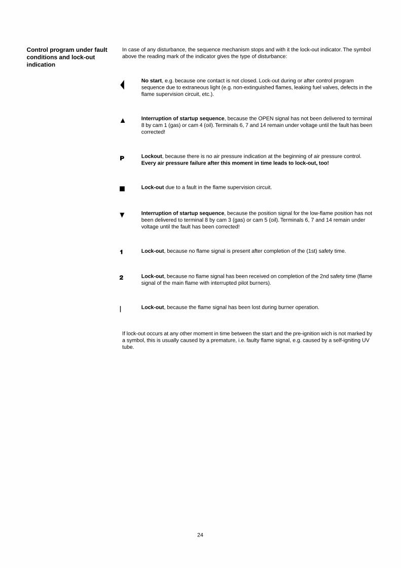
Control program under fault conditions and lock-out indication
In case of any disturbance, the sequence mechanism stops and with it the lock-out indicator. The symbol above the reading mark of the indicator gives the type of disturbance:
No start , e.g. because one contact is not closed. Lock-out during or after control program sequence due to extraneous light (e.g. non-extinguished flames, leaking fuel valves, defects in the flame supervision circuit, etc.).
Interruption of startup sequence , because the OPEN signal has not been delivered to terminal 8 by cam 1 (gas) or cam 4 (oil). Terminals 6, 7 and 14 remain under voltage until the fault has been corrected!
Lockout , because there is no air pressure indication at the beginning of air pressure control.Every air pressure failure after this moment in time leads to lock-out, too!
Lock-out due to a fault in the flame supervision circuit.
Interruption of startup sequence , because the position signal for the low-flame position has not been delivered to terminal 8 by cam 3 (gas) or cam 5 (oil). Terminals 6, 7 and 14 remain under voltage until the fault has been corrected!
Lock-out , because no flame signal is present after completion of the (1st) safety time.
Lock-out , because no flame signal has been received on completion of the 2nd safety time (flame signal of the main flame with interrupted pilot burners).
Lock-out , because the flame signal has been lost during burner operation.
If lock-out occurs at any other moment in time between the start and the pre-ignition wich is not marked by a symbol, this is usually caused by a premature, i.e. faulty flame signal, e.g. caused by a self-igniting UV tube.
P
1
2

25
BURNER START UP REPORT
Model number:
Project name:
Installing contractor:
Serial number:
Start-up date:
Phone number:
GAS OPERATION
Gas Supply Pressure:
Main Power Supply:
Control Power Supply:
Burner Firing Rate:
Manifold Pressure:
Pilot Flame Signal:
Low Fire Flame Signal:
High Fire Flame Signal:
CO2: Low Fire
O2: Low Fire
CO: Low Fire
NOX: Low Fire
Net Stack Temp - Low Fire:
Comb. Efficiency - Low Fire:
Overfire Draft:
High Fire
High Fire
High Fire
High Fire
High Fire:
High Fire:
OIL OPERATION
Oil supply pressure:
Oil suction pressure:
Control Power Supply:
Burner Firing Rate:
Low Fire Flame Signal:
High Fire Flame Signal:
Low Fire Nozzle Size:
High Fire Nozzle Size:
CO2: Low Fire
O2: Low Fire
CO: Low Fire
NOX: Low Fire
Net Stack Temp - Low Fire:
Comb. Efficiency - Low Fire:
Overfire Draft:
Smoke number:
High Fire
High Fire
High Fire
High Fire
High Fire:
High Fire:
CONTROL SETTINGS
Operating Setpoint:
High Limit Setpoint:
Low Gas Pressure:
High Gas Pressure:
Low Oil Pressure:
High Oil Pressure:
Flame Safeguard Model Number:
Modulating Signal Type:
NOTES

Represented By:Power Equipment Company
2011 Williamsburg RoadRichmond, VA 23231
Ph: 804-236-3800Fx: 804-236-3882www.peconet.com