Dual Band CDMA Cellular Modem - arcelect.com · Dual Band CDMA Cellular Modem Version 1.1 Mar 21,...
13
CCL 201 USER GUIDE Dual Band CDMA Cellular Modem Version 1.1 Mar 21, 2003 AYANTRA Inc.
Transcript of Dual Band CDMA Cellular Modem - arcelect.com · Dual Band CDMA Cellular Modem Version 1.1 Mar 21,...

CCL 201 USER GUIDE
Dual Band CDMA Cellular Modem
Version 1.1 Mar 21, 2003
AYANTRA Inc.
Wayne Ware
Text Box
Distributed by ARC Electronics

Ayantra Inc. 2
Contents
1. CCL 201 DESCRIPTION .................................................. 3
1.1 LED Description ..................................................................... 3 1.2 Serial Port Pins ...................................................................... 4 1.3 DIP Switch Settings................................................................... 4
1.3.1 DTE Speed................................................................................................................. 5 1.3.2 Auto Answer .............................................................................................................. 5 1.3.3 Local Echo Enable ..................................................................................................... 5 1.3.4 Result Code Enable.................................................................................................... 5 1.3.5 Result Code Terse...................................................................................................... 6 1.3.6 Flow control............................................................................................................... 6 1.3.7 Host DTR Control...................................................................................................... 6 1.3.8 DCD Indicator............................................................................................................ 6 2. BASIC SETUP .................................................................. 6 3. “AT” COMMANDS REFERENCE...................................... 7
3.1 Operational States..................................................................... 7 3.2 Basic Sets of Commands .......................................................... 8
3.2.1 Basic AT Parameters ................................................................................................. 8 3.2.2 Extended Configuration Commands........................................................................ 10 3.2.3 Cellular CDMA “AT” Commands .......................................................................... 11
3.3 Result Codes........................................................................... 12 4. LIMITED WARRANTY .................................................... 13

Ayantra Inc. 3
1. CCL 201 DESCRIPTION
The CCL 201, Dual Band (800 and 1900 MHz) CDMA Cellular Modem is an industrial grade digital modem incorporating data compression and error detection techniques for a data throughput of up to 57.6 Kbps. CCL 201 can be configured without a PC by using the DIP switch located on the front of the unit. Typically no familiarity with “AT” commands is required. This User Guide explains how to set up and configure the unit.
Figure 1. CCL 201
1.1 LED Description The unit has five LED indicators that are located on top of the unit (see Figure 1).
LED name Description TX Serial line activity (Transmit Data) RX Serial line activity (Receive Data) DTR Data Terminal Ready CD Carrier Detect indicating that modem connection is ON MR Modem Ready

Ayantra Inc. 4
1.2 Serial Port Pins The DB9 serial port conforms to the standard RS232 connection as shown below:
Figure 2. DB9 Female DCE Interface RS-232
Table 1. Serial Port Pins
1.3 DIP Switch Settings Most commonly used parameters can be set on the CCL 201 by using the DIP switches on the front of the unit (see Figure 3).
Figure 3. DIP Switches
Note: The default settings are highlighted in YELLOW.
Pin No. Signal Name Description 1 CD Carrier Detect 2 RX Receive Data 3 TX Transmit Data 4 DTR Data Terminal
Ready 5 GND Ground 6 DSR Data Set Ready 7 RTS Request To Send 8 CTS Clear To Send 9 RI Ring Indicator

Ayantra Inc. 5
1.3.1 DTE Speed Host Serial Port baud rate settings:
Switch 1 Switch 2 Switch 3 Serial Baud rate
ON ON ON 1200 bps ON ON OFF 2400 bps ON OFF ON 4800 bps ON OFF OFF 9600 bps OFF ON ON 19200 bps OFF ON OFF 38400 bps OFF OFF ON 57600 bps OFF OFF OFF 115200 bps
1.3.2 Auto Answer
Switch 4 Auto Answer ON Auto Answer On (Modem will answer incoming ring) OFF Auto Answer Off (Modem will not answer incoming ring)
1.3.3 Local Echo Enable Generally local echo is turned ON.
Switch 5 Local Echo Enable ON Enable Local Echo (Input commands will be echoed back) OFF Disable Local Echo ATE0
1.3.4 Result Code Enable Result code is enabled for most applications.
Switch 6 Result Code Enable ON Result code enable (Unit will send back results of actions taken) OFF Disable Result code
Ayantra Inc. 6
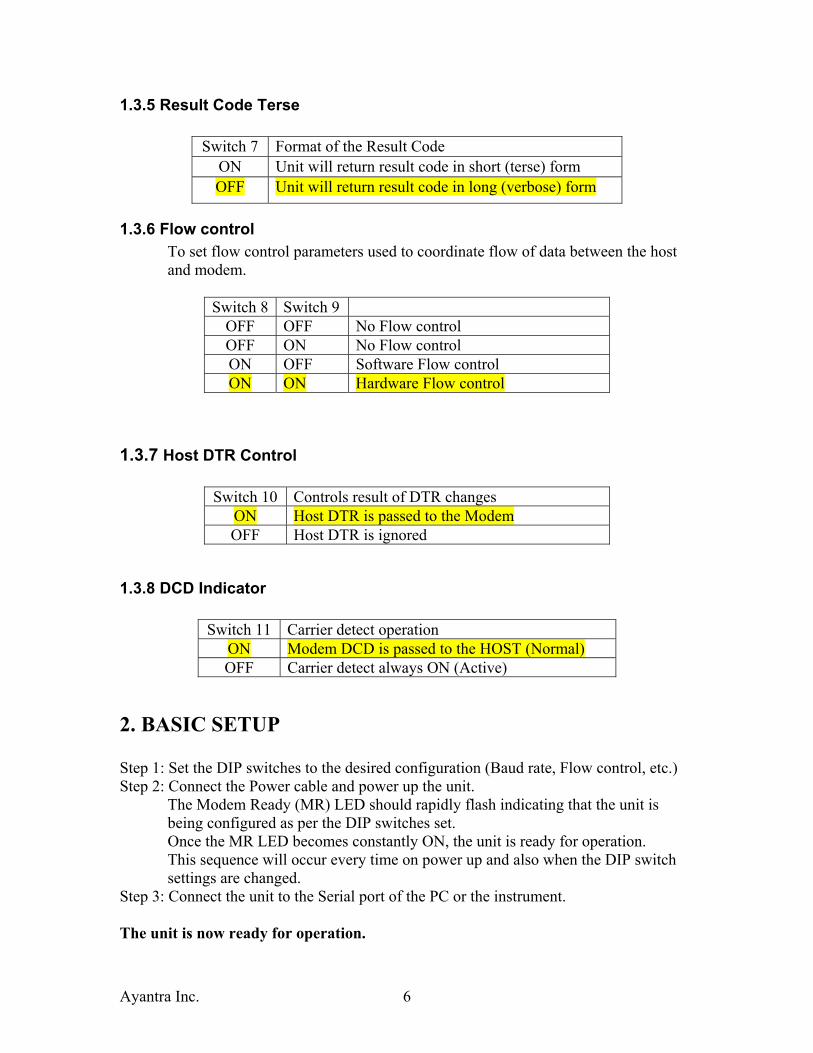
1.3.5 Result Code Terse
Switch 7 Format of the Result Code ON Unit will return result code in short (terse) form OFF Unit will return result code in long (verbose) form
1.3.6 Flow control To set flow control parameters used to coordinate flow of data between the host and modem.
Switch 8 Switch 9 OFF OFF No Flow control OFF ON No Flow control ON OFF Software Flow control ON ON Hardware Flow control
1.3.7 Host DTR Control
Switch 10 Controls result of DTR changes ON Host DTR is passed to the Modem OFF Host DTR is ignored
1.3.8 DCD Indicator
Switch 11 Carrier detect operation ON Modem DCD is passed to the HOST (Normal) OFF Carrier detect always ON (Active)
2. BASIC SETUP Step 1: Set the DIP switches to the desired configuration (Baud rate, Flow control, etc.) Step 2: Connect the Power cable and power up the unit.
The Modem Ready (MR) LED should rapidly flash indicating that the unit is being configured as per the DIP switches set. Once the MR LED becomes constantly ON, the unit is ready for operation. This sequence will occur every time on power up and also when the DIP switch settings are changed.
Step 3: Connect the unit to the Serial port of the PC or the instrument. The unit is now ready for operation.
Ayantra Inc. 7
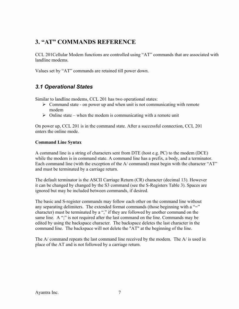
3. “AT” COMMANDS REFERENCE CCL 201Cellular Modem functions are controlled using “AT” commands that are associated with landline modems.
Values set by “AT” commands are retained till power down.
3.1 Operational States Similar to landline modems, CCL 201 has two operational states:
Command state - on power up and when unit is not communicating with remote modem Online state – when the modem is communicating with a remote unit
On power up, CCL 201 is in the command state. After a successful connection, CCL 201 enters the online mode.
Command Line Syntax
A command line is a string of characters sent from DTE (host e.g. PC) to the modem (DCE) while the modem is in command state. A command line has a prefix, a body, and a terminator. Each command line (with the exception of the A/ command) must begin with the character “AT” and must be terminated by a carriage return.
The default terminator is the ASCII Carriage Return (CR) character (decimal 13). However it can be changed by changed by the S3 command (see the S-Registers Table 3). Spaces are ignored but may be included between commands, if desired.
The basic and S-register commands may follow each other on the command line without any separating delimiters. The extended format commands (those beginning with a “=” character) must be terminated by a “,” if they are followed by another command on the same line. A “;” is not required after the last command on the line. Commands may be edited by using the backspace character. The backspace deletes the last character in the command line. The backspace will not delete the "AT" at the beginning of the line.
The A/ command repeats the last command line received by the modem. The A/ is used in place of the AT and is not followed by a carriage return.
Ayantra Inc. 8
3.2 Basic Sets of Commands Types of Commands: For the CCL 201 there are three types of commands:
1. Basic AT parameters (including those for setting S-registers) 2. Extended Configuration commands 3. Cellular CDMA “AT” commands
3.2.1 Basic AT Parameters
These commands control the basic configuration of the modem. The parameters can only be read back by &V command when in command state. The following Table 2. shows the command format.

Ayantra Inc. 9
Table 2. Basic AT Parameters
S-Registers
Register Value Description S0
0 (1)
Disable automatic answering Enable automatic answering on ring detect.
S7 1 to 255
Number of seconds to establish end-to-end data connection. The default is 50 seconds.
S8 0 to 255
Number of seconds to pause when “,” is encountered in dial string. Default value is two seconds.
Parameter Description
A Go off hook. Answer any incoming call
D<dial string> <CR>
The dial string may contain the following characters: Digits 0 to 9, *, #, A,B,C, and D The dial string may contain the following dial modifiers: T Tone dialing , Pause during dialing ; After dialing, the modem remains in command state
H0 Disconnect and return to command state
O0 Return to online data state from command state
E0 Do not echo commands when in command state
E1 Echo commands when in command state
Q0 Returns result codes. This is the normal mode.
Q1 Do not return result codes. Called quite mode.
V0 Display result codes as numbers. Called terse mode.
V1 Display result codes as words. Called verbose mode.
&C0 Carrier detect always ON
&C1 Carrier detect ON when modem is connected and OFF when connectis lost
&D0 Ignore DTR
&D2 Enter command state following On to Off transition of DTR
&V Display configuration parameters

Ayantra Inc. 10
S10 1 to 254
Time to detect loss of carrier. Default value of 14 indicates 1.4 seconds.
Table 3. S-Registers
NOTE: S-register values are not saved upon power down.
3.2.2 Extended Configuration Commands
Command Description
+GMI This command causes the modem to transmit one or more lines of information text, determined by the manufacturer, which is intended to permit the user of the modem to identify the manufacturer. Typically, the text will consist of a single line containing the name of the manufacturer, but manufacturers may choose to provide more information if desired (e.g., address, telemodem number for customer service, etc.)
+GMM This command causes the modem to transmit one or more lines of information text, determined by the manufacturer, which is intended to permit the user of the modem to identify the specific model of the device. Typically, the text willconsist of a single line containing the name of the product, bug manufacturers may choose to provide any information desired
+GSN This command causes the modem to transmit one or more lines of information text, determined by the manufacturer, which is intended to permit the user of the modem to identify the individual device. Typically, the text will consist of a single line containing a manufacturer determined alpha-numeric string, but manufacturers may choose to provide any information desired
+IFC Local Flow Control. This extended-format compound parameter is used to control the operation of local flow control between the host terminal and modem
+IPR Fixed data rate. This numeric extended-format parameter specifies the data rate at which the modem will accept commands, in addition to 1200 bit/s or 9600 bit/s (as required in EIA/TIA-602). It may be used to select operation at a rate at which the modem is not capable of automatically detecting the data rate being used by the host terminal
Table 4. Extended Configuration Commands
Ayantra Inc. 11
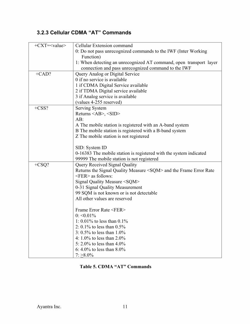
3.2.3 Cellular CDMA “AT” Commands
+CXT=<value> Cellular Extension command 0: Do not pass unrecognized commands to the IWF (Inter Working Function) 1: When detecting an unrecognized AT command, open transport layer
connection and pass unrecognized command to the IWF +CAD? Query Analog or Digital Service
0 if no service is available 1 if CDMA Digital Service available 2 if TDMA Digital service available 3 if Analog service is available (values 4-255 reserved)
+CSS? Serving System Returns <AB>, <SID> AB: A The mobile station is registered with an A-band system B The mobile station is registered with a B-band system Z The mobile station is not registered SID: System ID 0-16383 The mobile station is registered with the system indicated 99999 The mobile station is not registered
+CSQ? Query Received Signal Quality Returns the Signal Quality Measure <SQM> and the Frame Error Rate <FER> as follows: Signal Quality Measure <SQM> 0-31 Signal Quality Measurement 99 SQM is not known or is not detectable All other values are reserved Frame Error Rate <FER> 0: <0.01% 1: 0.01% to less than 0.1% 2: 0.1% to less than 0.5% 3: 0.5% to less than 1.0% 4: 1.0% to less than 2.0% 5: 2.0% to less than 4.0% 6: 4.0% to less than 8.0% 7: >8.0%
Table 5. CDMA “AT” Commands

Ayantra Inc. 12
3.3 Result Codes When in the command mode, nine possible result codes may be returned. The digit code (terse) is returned when the verbose mode is OFF; the word code (verbose) is returned when the verbose mode is ON. See the ‘V’ command in the Basic AT Parameters Table 2.
Digit Verbose Description 0 OK Command executed without errors 1 CONNECT Connected to remote modem 2 RING Incoming Call 3 NO
CARRIER Carrier from remote modem lost or never present
4 ERROR Error in the command line 6 NO
DIALTONE No dial tone detected within time out period
7 BUSY Busy signal detected
8 NO ANSWER
Five seconds of silence not detected after ring back when @ dial modifier is used
Table 6. Result Codes

Ayantra Inc. 13
4. LIMITED WARRANTY Ayantra (“Company”) warrants that it’s product shall be free from defects in material and workmanship for a period of one year from the date of shipment. Ayantra warrants any software sold alone or with any of its’ products shall be free from defects (according to the Company’s specification) for a period of sixty (60) days from the date of shipment. During the warranty period, if the customer experiences difficulties and is unable to resolve the problem by modem with Company’s Technical Support, the Company will issue a Return Material Authorization (RMA) number. Following the receipt of a RMA number, the customer is responsible for returning the product to the Company, freight prepaid. Upon verification of the warranty, the Company will, at its option, repair or replace the product in question, and return it by prepaid freight. This warranty does not cover any work or services at the customer’s site. Any software revisions required hereunder cover supply of distribution media only. The warranty does not cover, or include, any installation that may be required. Company shall have no obligation to make repairs or to cause replacement required through normal wear and tear necessitated in whole or in part by catastrophe, fault or negligence of the user, improper or unauthorized use of the Product, or use of the Product in such a manner for which it was not designed, or by causes external to the Product, such as, but not limited to, power or failure due to extreme temperatures. The information, recommendation, description and safety notations in this or other documents supplied by Company are based on general industry experience and judgment with respect to such hardware and software. This information should not be considered to be all-inclusive or covering all contingencies. In no event will Ayantra be responsible to the user in contract, in tort (including negligence), strict liability or otherwise for any special, indirect, incidental or consequential damage or loss of equipment, plant or power system, cost of capital, loss of profit. The above represents the entire obligation of the Company and understanding between the parties. There are no other understandings, agreements, representations or warranties, express or implied, including warranties of merchantability or fitness for a particular purpose.