º DUAL AXIS Angle vs. Output Voltage º SINGLE AXIS SQ-SI-360DA.pdfThe inclinometer module performs...
13
DATASHEET SQ-SI-360DA SOLID-STATE MEMS INCLINOMETER ±70 º DUAL AXIS, 360 º SINGLE AXIS, SERIAL AND ANALOG OUTPUT Updated: 2014-01-16 © SignalQuest, LLC 2014 10 Water St. Lebanon, NH 03766 USA Tel: 603.448.6266 Fax 603.218.6426 www.signalquest.com [email protected] 1 SQ-SI-360DA-HMP SQ-SI-360DA-VMP FUNCTIONAL DIAGRAMS EXAMPLE ANALOG OUTPUT The graph below shows an example of the analog output from a device in single axis mode. The device is rotated 720º clockwise from a 0º starting position at a rate of 180º/sec. The output is linear with a piecewise overflow at 360º. The second axis output is similar, but each axis reaches a maximum at 180º and descends back to 0º rather than overflowing. RANGE AND SCALE PARAMETER UNITS VALUE Scale Factor V/deg 0.0022 × V cc Offset (0º value) V 0.100 × V cc Max (359º value ) V 0.895 × V cc (deg) ) V/deg ( ) V ( ) V ( Angle r ScaleFacto Offset Output ) V/deg ( ) V ( ) V ( (deg) r ScaleFacto Offset Output Angle FUNCTION ± 70 º dual axis angle measurement 360 º single axis angle measurement UART serial output and analog output APPLICATIONS Platform and vehicle leveling Satellite dish and antenna alignment Machine control and monitoring Angle measurement and recording Computer input, head tracking, and mouse pointing DESCRIPTION The inclinometer module performs calibrated angle measurement with analog voltage and digital serial outputs. FEATURES 0.1 º resolution - digital serial output Low temperature drift Factory calibrated angle output High reliability solid-state MEMS Digital filtering for stable measurement Direct PC interface cable Made in the USA THEORY OF OPERATION The inclinometer uses two factory calibrated accelerometers to measure and compute angles made between its axes and the gravity vector. The trigonometric conversions between acceleration and angle are made by an onboard processor. Digital filtering reduces the impact of spurious acceleration and vibration on the reported angle. Angle vs. Output Voltage 0.000 0.500 1.000 1.500 2.000 2.500 3.000 3.500 0 90 180 270 0 90 180 270 Angle (deg) Output Voltage (volts) Angle (deg)
-
Upload
dinhkhuong -
Category
Documents
-
view
219 -
download
3
Transcript of º DUAL AXIS Angle vs. Output Voltage º SINGLE AXIS SQ-SI-360DA.pdfThe inclinometer module performs...
DATASHEET
SQ-SI-360DA
SOLID-STATE MEMS INCLINOMETER
±70 º DUAL AXIS, 360 º SINGLE AXIS, SERIAL AND ANALOG OUTPUT
Updated: 2014-01-16 © SignalQuest, LLC
2014
10 Water St.
Lebanon, NH 03766 USA
Tel: 603.448.6266
Fax 603.218.6426
www.signalquest.com
1
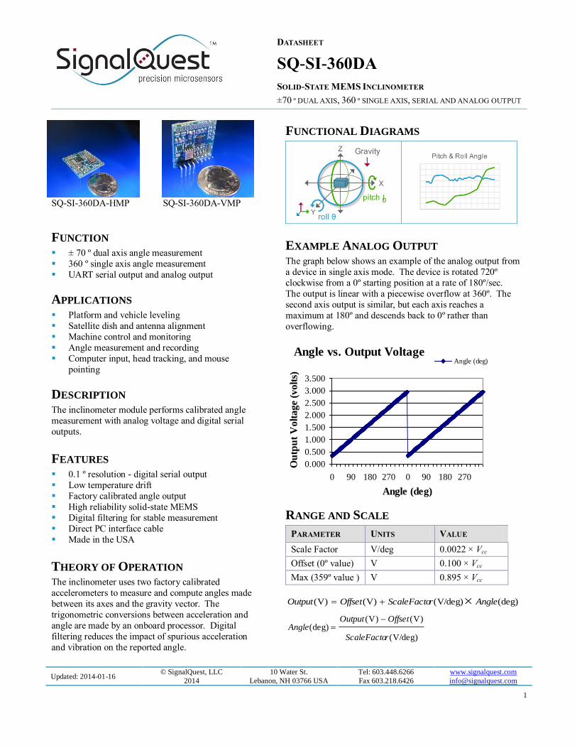
SQ-SI-360DA-HMP SQ-SI-360DA-VMP
FUNCTIONAL DIAGRAMS
EXAMPLE ANALOG OUTPUT The graph below shows an example of the analog output from
a device in single axis mode. The device is rotated 720º
clockwise from a 0º starting position at a rate of 180º/sec.
The output is linear with a piecewise overflow at 360º. The
second axis output is similar, but each axis reaches a
maximum at 180º and descends back to 0º rather than
overflowing.
RANGE AND SCALE
PARAMETER UNITS VALUE
Scale Factor V/deg 0.0022 × Vcc
Offset (0º value) V 0.100 × Vcc
Max (359º value ) V 0.895 × Vcc
(deg))V/deg()V()V( AnglerScaleFactoOffsetOutput
)V/deg(
)V()V((deg)
rScaleFacto
OffsetOutputAngle
FUNCTION ± 70 º dual axis angle measurement
360 º single axis angle measurement
UART serial output and analog output
APPLICATIONS
Platform and vehicle leveling
Satellite dish and antenna alignment
Machine control and monitoring
Angle measurement and recording
Computer input, head tracking, and mouse
pointing
DESCRIPTION The inclinometer module performs calibrated angle
measurement with analog voltage and digital serial
outputs.
FEATURES 0.1 º resolution - digital serial output
Low temperature drift
Factory calibrated angle output
High reliability solid-state MEMS
Digital filtering for stable measurement
Direct PC interface cable
Made in the USA
THEORY OF OPERATION The inclinometer uses two factory calibrated
accelerometers to measure and compute angles made
between its axes and the gravity vector. The
trigonometric conversions between acceleration and
angle are made by an onboard processor. Digital
filtering reduces the impact of spurious acceleration
and vibration on the reported angle.
Angle vs. Output Voltage
0.000
0.500
1.000
1.500
2.000
2.500
3.000
3.500
0 90 180 270 0 90 180 270
Angle (deg)
Ou
tpu
t V
olt
ag
e (v
olt
s)
Angle (deg)

DATASHEET
SQ-SI-360DA
SOLID-STATE MEMS INCLINOMETER
±70 º DUAL AXIS, 360 º SINGLE AXIS, SERIAL AND ANALOG OUTPUT
Updated: 2014-01-16 © SignalQuest, LLC
2014
10 Water St.
Lebanon, NH 03766 USA
Tel: 603.448.6266
Fax 603.218.6426
www.signalquest.com
2
TABLE OF CONTENTS
Absolute Maximum Ratings ................................................................................................................................................. 3
Electrical Characteristics ...................................................................................................................................................... 3
Performance Parameters ....................................................................................................................................................... 4
Output Characteristics .......................................................................................................................................................... 4
Pin Configuration ................................................................................................................................................................. 5
Design, Layout, and Assembly Considerations ...................................................................................................................... 7
Serial Interface: HP and LP Versions ..................................................................................................................................... 7
Example Output: HP and LP versions* ................................................................................................................................. 9
Orientation ......................................................................................................................................................................... 10
Ordering Guide .................................................................................................................................................................. 11
Accessories ........................................................................................................................................................................ 12
Limitations and Warnings ................................................................................................................................................... 13
Testing ............................................................................................................................................................................... 13
System Integration Testing ................................................................................................................................................. 13

DATASHEET
SQ-SI-360DA
SOLID-STATE MEMS INCLINOMETER
±70 º DUAL AXIS, 360 º SINGLE AXIS, SERIAL AND ANALOG OUTPUT
Updated: 2014-01-16 © SignalQuest, LLC
2014
10 Water St.
Lebanon, NH 03766 USA
Tel: 603.448.6266
Fax 603.218.6426
www.signalquest.com
3
ABSOLUTE MAXIMUM RATINGS
PARAMETER MIN TYPICAL MAX NOTES
Voltage on +Vcc - without regulator - NR option - 4.2 V With respect to GND
Voltage on +Vcc - with regulator - R option - 5.8 V
Voltage on any input pin 5.8 V With respect to GND
Peak-to-peak supply noise - without regulator -NR option 50 mV
Peak-to-peak supply noise - with regulator - R option 200 mV
Operating temperature -40 ºC 85 ºC
Shock survivability 500 gn Where 1 gn is assumed
to be = 9.81 m/s2
Operating vibration 0.25 gn
Note: Exposure to conditions outside of the Absolute Maximum Ratings may damage the device. Prolonged exposure to
conditions at the Absolute Maximum Ratings may result in degraded performance of the device over time.
ELECTRICAL CHARACTERISTICS [Test conditions: 3.3v regulator, 25 ºC unless otherwise specified]
PARAMETER MIN TYPICAL MAX NOTES
Supply voltage - without regulator - NR option 2.9 V 3.5 V With respect to GND
12 V versions also available. Consult the
factory.
Supply voltage - with 3.0 volt regulator - 3.0R option 3.2 V 5.8 V
Supply voltage - with 3.3 volt regulator - 3.3R option 3.5 V 5.8 V
Supply current - HP option 4.6 mA
Supply current - LP option 1.6 mA
Supply current - ULP option 0.5 µA 40 µA 1.9 mA
Operating at 1 sample
per second, no filtering,
no oversampling
Output voltage* 0.3 V 0.9 × Vcc
See note below
regarding Vcc Sensitivity*
0.0022 ×
Vcc /deg
Full-scale output range* 0.100 × Vcc 0.895 × Vcc
Analog output current 20 µA
Input voltage High 2.0 V
Input voltage Low 0.8 V
Output voltage High 0.895 × Vcc Vcc
Output voltage Low 0 V 0.100 × Vcc
*Note: For the NR model (without onboard regulator), Vcc is the voltage supplied to the device. For the 3.0R and 3.3R
models (3.0 V or 3.3 V onboard regulators), Vcc is 3.0 V or 3.3 V respectively. If your application requires using a 12 V
supply, consult the factory for 12 V models.

DATASHEET
SQ-SI-360DA
SOLID-STATE MEMS INCLINOMETER
±70 º DUAL AXIS, 360 º SINGLE AXIS, SERIAL AND ANALOG OUTPUT
Updated: 2014-01-16 © SignalQuest, LLC
2014
10 Water St.
Lebanon, NH 03766 USA
Tel: 603.448.6266
Fax 603.218.6426
www.signalquest.com
4
PERFORMANCE PARAMETERS [Test conditions: 3.3v regulator, 25 º C unless otherwise specified]
PARAMETER SPECIFICATION NOTES
Angle accuracy (differential) - HP option ± 1 º From any angle to any other angle within
range Angle accuracy (differential) - LP option ± 2 º
Angle accuracy (differential) - ULP option ± 2 º
Angle resolution 2 º (analog), 0.1 º (digital)
Alignment accuracy ± 2 º
Angle range - Dual Axis Tilt Mode ± 70 º (X and Y tilt) Dual axis X and Y tilt angle ranges with
respect to horizontal.
Angle range - Single Axis Gimbaled
Mode 360 º (Z rotation)
Single axis rotation angle measurement valid
while Z axis (vector normal to circuit board)
is within ± 45 º of horizontal.*
Typical angular drift due to temperature.
Values represent 1 sigma confidence in tilt
mode. - IND option
Angle range
± 10 º ± 45 º ± 70 º
**
360 º
(single axis)
Tem
per
atu
re
ra
ng
e
15 C to +35 C ± 0.06 º ± 0.06 º ± 0.3 º ± 0.1 º
0 C to +70 C ± 0.3 º ± 0.3 º ± 1.6 º ± 0.6 º
-40 C to +85 C ± 0.4 º ± 0.4 º ± 1.7 º ± 0.8 º
Typical angular drift due to temperature. Values represent 1 sigma confidence in tilt
mode. - LC option
Angle range
± 10 º ± 45 º ± 70 º
**
360 º
(single axis)
Tem
per
atu
re
ra
ng
e
15 C to +35 C ± 0.3 º ± 0.3 º ± 1.7 º ± 0.6 º
0 C to +70 C ± 1.3 º ± 1.4 º ± 7.8 º ± 2.8 º
-40 C to +85 C ± 1.9 º ± 2.1 º ± 8.5 º ± 4.2 º
* Note: Angle ranges measured with respect to deviations from horizontal.
** Note: Useable up to +/- 80 º with degraded accuracy.
OUTPUT CHARACTERISTICS
PARAMETER – HP AND LP VERSIONS TYPICAL NOTES
Update rate - HP option 40 Hz
Analog update rate and digital serial packet rate Update rate - LP option 5 Hz
Update rate - ULP option 2 Hz
Warm up time from power on - S option 1.0 s
Angle jitter and vibration are digitally filtered Measurement settling time - S option 0.5 s
Warm up time from power on - F option 0.2 s
Measurement settling time - F option 0.1 s
Analog output resolution 8 bit 9 bit actual resolution after PWM reconstruction

DATASHEET
SQ-SI-360DA
SOLID-STATE MEMS INCLINOMETER
±70 º DUAL AXIS, 360 º SINGLE AXIS, SERIAL AND ANALOG OUTPUT
Updated: 2014-01-16 © SignalQuest, LLC
2014
10 Water St.
Lebanon, NH 03766 USA
Tel: 603.448.6266
Fax 603.218.6426
www.signalquest.com
5
filter
PWM modulation frequency 5 kHz to 20 kHz
PWM reconstruction filter bandwidth 10 Hz Single pole RC
Output impedance 10 kΩ
PARAMETER – ULP VERSION TYPICAL NOTES
Update rate - ULP option On demand up to 20 Hz Serial output only. Analog output disabled.
PIN CONFIGURATION
PIN SIGNAL NAME USAGE
1 Ground
2 UART Transmit
Digital Output – UART transmit line. Push-pull (not open collector). If not used, solder to
open circuit for mechanical stability. Do not connect to GND or current drain will increase.
3 UART Receive Digital Input – UART receive line. If not used, solder to V+.
4 Baud Select Digital Input – HP and LP version only. High (or open) selects high baud rate. Low selects
low baud rate. If not used, solder to V+.
5 +Vcc Supply
6 Y Tilt / Z Rotation
Output
Analog Output – If not used, solder to open circuit for mechanical stability. Do not connect
to GND or current drain will increase.
7 X Tilt / Z Tilt Output Analog Output – If not used, solder to open circuit for mechanical stability. Do not connect
to GND or current drain will increase.
8 Dual Axis Tilt Mode / Single Axis
Gimbaled Mode
Select
Digital Input – High (or open) selects Dual Axis Tilt Mode, Low selects Single Axis Gimbaled Mode. If not used, solder to open circuit for mechanical stability.
9 Noise Estimator Solder to open circuit for mechanical stability. Do not connect to GND
10 NC Solder to open circuit for mechanical stability. Do not connect to GND.
11 Self Test Solder to open circuit for mechanical stability. Do not connect to GND
12 Resolution Select Solder to open circuit for mechanical stability. Do not connect to GND
13 Flip X-Y Solder to open circuit for mechanical stability. Do not connect to GND
14 NC Solder to open circuit for mechanical stability. Do not connect to GND
15 /Reset & Prog 1 Digital Input – Active low reset. Bring low for >10 mS to reset device. If not used, solder
to open circuit for mechanical stability. Do not connect to GND. Also used for FLASH
programming.
16 Prog 2 Digital Input – If not used, solder to open circuit for mechanical stability. Do not connect to
GND. Also used for FLASH programming.
17 NC Solder to open circuit for mechanical stability. Do not connect to GND
18 NC Solder to open circuit for mechanical stability. Do not connect to GND
*Note: Grey boxes indicate that a signal is available only on a custom application basis. NC means “no connection”.

DATASHEET
SQ-SI-360DA
SOLID-STATE MEMS INCLINOMETER
±70 º DUAL AXIS, 360 º SINGLE AXIS, SERIAL AND ANALOG OUTPUT
Updated: 2014-01-16 © SignalQuest, LLC
2014
10 Water St.
Lebanon, NH 03766 USA
Tel: 603.448.6266
Fax 603.218.6426
www.signalquest.com
6
SQ-SI-360DA SERIES PACKAGE
DIMENSIONS
DIMENSION MILLIMETERS INCHES DESCRIPTION NOTES
T 10.16 0.40 N/A Pin center to center
L 25.40 1.00 Side length
E 2.54 0.10 Pitch Pin center to center
D 0.80 0.032 Pin diameter
DD 1.00 0.040 Hole diameter
N 1.63 0.064 PCB thickness
S 20.32 0.80 Pin row spacing

DATASHEET
SQ-SI-360DA
SOLID-STATE MEMS INCLINOMETER
±70 º DUAL AXIS, 360 º SINGLE AXIS, SERIAL AND ANALOG OUTPUT
Updated: 2014-01-16 © SignalQuest, LLC
2014
10 Water St.
Lebanon, NH 03766 USA
Tel: 603.448.6266
Fax 603.218.6426
www.signalquest.com
7
DESIGN, LAYOUT, AND ASSEMBLY CONSIDERATIONS 1. Since the device is a subassembly of surface mount components, it is not suitable for automatic assembly or wave
soldering.
2. Hand soldering of pins or SMT pads is specified for 3 seconds at 218 ºC.
3. Pins labeled NC (no connect) should be soldered to open connection pads / pins for mechanical stability.
4. The designer should test the device’s output voltage through its entire desired angle range during prototyping to
ensure that it is working properly in the application.
5. The device can be mounted vertically or horizontally, but the direction must be oriented correctly to measure the
desired angles.
SERIAL INTERFACE: HP AND LP VERSIONS*
UART FORMAT: 8-N-1
8 data bits, 1 stop bit, no parity, no flow control: 115,200 baud or 57,600 baud, pin-selectable. (Available in 19,200 baud by
special order.)
One byte commands can be sent from the host to control various functions of the device. The following commands can be
sent to the devices via the UART. The data encoding is HEX, not ASCII.
INTERROGATE
0x01 (Interrogate Mode command)
The inclinometer responds with one data packet [10 bytes] after receiving the Interrogate Mode command. The maximum delay between a request and the data packet response is 1 Update Period. The host should not issue a new Interrogate Mode
command before it has received a response to a previous Interrogate Mode command.
STREAM
0x02 (Stream Mode command)
The inclinometer begins sending data packets [10 bytes] continuously at the given Update Rate. The maximum delay
between a request and the first data packet response is one Update Period.
RESET
0x83 (Reset command)
The inclinometer initiates its Power-on Reset sequence (see Power-on Reset below).
RESET SOURCES
Power-on Reset and RST pin
When the inclinometer is disconnected from power it reverts to its default settings in Interrogate Mode. It transmits 1 data
packet [10 bytes] after its Warm Up time to indicate that measurements are stabilized.
* For the ULP version see the document “SQ-SI ULP Addendum” available at http://www.signalquest.com

DATASHEET
SQ-SI-360DA
SOLID-STATE MEMS INCLINOMETER
±70 º DUAL AXIS, 360 º SINGLE AXIS, SERIAL AND ANALOG OUTPUT
Updated: 2014-01-16 © SignalQuest, LLC
2014
10 Water St.
Lebanon, NH 03766 USA
Tel: 603.448.6266
Fax 603.218.6426
www.signalquest.com
8
SERIAL PACKET FORMAT: HP AND LP VERSIONS
BYTE DUAL AXIS TILT
MODE
SINGLE AXIS
GIMBALED MODE NOTES
Hea
der
0 Sync byte 1 Sync byte 1 0xFE
1 Sync byte 2 Sync byte 2 0xFE
Pay
load
2 X Tilt
(high byte)
Z Rotation
(high byte)
Format: 16-bit, unsigned integer
Output_Value = Measured_Angle × 10.
For example, a measured angle of 127.5 º results in an
output value of 1275.
3 X Tilt
(low byte)
Z Rotation
(low byte)
4 Y Tilt
(high byte)
Z Tilt*
(high byte)
5 Y Tilt
(low byte)
Z Tilt*
(low byte)
6 Factory1 Factory1
(high byte) Undefined
7 Factory2 Factory2
(low byte)
Ch
eck
sum
8 Checksum (high) Checksum (high) Format: 16-bit, unsigned integer sum of the 16 bit unsigned
integer payload values. The checksum does not include the
two sync bytes (0xFE 0xFE). 9 Checksum (low) Checksum (low)
*Note: Z Tilt is not supported at this time. This measurement should be considered invalid. It may be used in several special
cases. Its range is 0 º to 80 º, but the output validity is not supported by this datasheet. Please consult the factory if you
would like to learn more about Z Tilt.
DATASHEET
SQ-SI-360DA
SOLID-STATE MEMS INCLINOMETER
±70 º DUAL AXIS, 360 º SINGLE AXIS, SERIAL AND ANALOG OUTPUT
Updated: 2014-01-16 © SignalQuest, LLC
2014
10 Water St.
Lebanon, NH 03766 USA
Tel: 603.448.6266
Fax 603.218.6426
www.signalquest.com
9
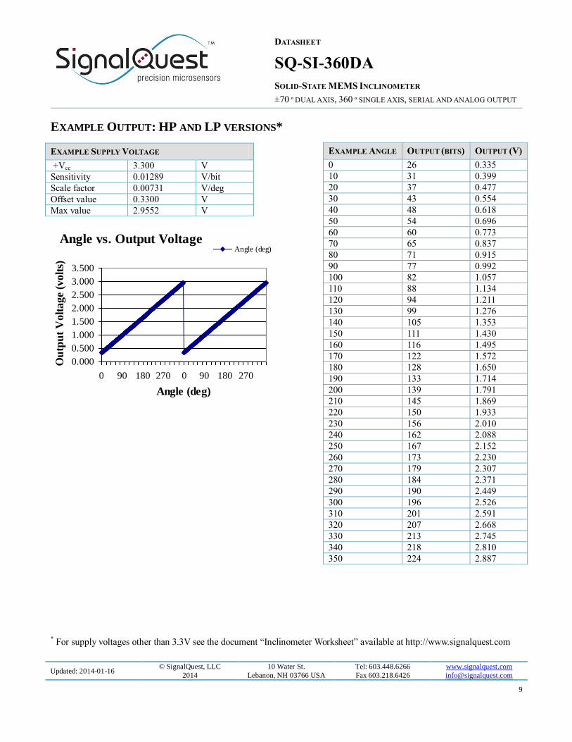
EXAMPLE OUTPUT: HP AND LP VERSIONS*
* For supply voltages other than 3.3V see the document “Inclinometer Worksheet” available at http://www.signalquest.com
Angle vs. Output Voltage
0.000
0.500
1.000
1.500
2.000
2.500
3.000
3.500
0 90 180 270 0 90 180 270
Angle (deg)
Ou
tpu
t V
olt
ag
e (v
olt
s)
Angle (deg)
EXAMPLE ANGLE OUTPUT (BITS) OUTPUT (V)
0 26 0.335
10 31 0.399
20 37 0.477
30 43 0.554
40 48 0.618
50 54 0.696
60 60 0.773
70 65 0.837
80 71 0.915
90 77 0.992
100 82 1.057
110 88 1.134
120 94 1.211
130 99 1.276
140 105 1.353
150 111 1.430
160 116 1.495
170 122 1.572
180 128 1.650
190 133 1.714
200 139 1.791
210 145 1.869
220 150 1.933
230 156 2.010
240 162 2.088
250 167 2.152
260 173 2.230
270 179 2.307
280 184 2.371
290 190 2.449
300 196 2.526
310 201 2.591
320 207 2.668
330 213 2.745
340 218 2.810
350 224 2.887
EXAMPLE SUPPLY VOLTAGE
+Vcc 3.300 V
Sensitivity 0.01289 V/bit
Scale factor 0.00731 V/deg
Offset value 0.3300 V
Max value 2.9552 V

DATASHEET
SQ-SI-360DA
SOLID-STATE MEMS INCLINOMETER
±70 º DUAL AXIS, 360 º SINGLE AXIS, SERIAL AND ANALOG OUTPUT
Updated: 2014-01-16 © SignalQuest, LLC
2014
10 Water St.
Lebanon, NH 03766 USA
Tel: 603.448.6266
Fax 603.218.6426
www.signalquest.com
10
ORIENTATION TERMINOLOGY
Gravity means a vector pointing from the device toward the center of the earth. X means a vector parallel to the white silkscreen arrow “X” printed on the main circuit board.
Y means a vector parallel to the white silkscreen arrow “Y” printed on the main circuit board.
Z means a vector passing through the white silkscreen dot “Z” printed on the main circuit board, at 90º to the board.
Horizontal means the silkscreen arrow is pointing at a right angle to gravity.
Straight Down means the silkscreen arrow is parallel to gravity.
Straight Up means that the silkscreen arrow is anti-parallel to gravity (i.e. pointing toward the sky).
Plumb Line is a line with a weight on the end hanging straight down.
DUAL AXIS TILT MODE
In Dual Axis Tilt Mode the X Tilt and Y Tilt angles are measured between gravity and the white silkscreen arrows printed on
the main circuit board. If you passed a Plumb Line through the inclinometer’s X, Y, Z origin, the X and Y Tilt angles could
be measured by placing a protractor’s straight edge on the plum line and then reading the angles made with each arrow.
Y Tilt = Pitch (first angle)
X Tilt = Roll (second angle)
Holding Y Horizontal
When X is Horizontal, X Tilt = 90 º.
When X is Straight Up, X Tilt = ~180 º.
When X is Straight Down, X Tilt = ~0 º.
Holding X Horizontal
When Y is Horizontal, Y Tilt = 90 º.
When Y is Straight Up, Y Tilt = ~180 º.
When Y is Straight Down, Y Tilt = ~0 º.
SINGLE AXIS GIMBALED MODE
In Single Axis Gimbaled Mode, the Z Rotation angle is defined as a rotation about the Z axis of the device. Typically, the
inclinometer will be mounted using the VMP package for Single Axis Gimbaled Mode operation. For the Z Axis Rotation angle to remain in range, the Z Axis must be near horizontal. The Z axis should be kept to less than ± 45 º of deviation from
horizontal.
.
When X is Horizontal, Y is Straight Up, Z Rotation = 0 / 360 º.
When Y is Horizontal, X is Straight Down, Z Rotation = 90 º.
When X is Horizontal, Y is Straight Down, Z Rotation = 180 º. When Y is Horizontal, X is Straight Up, Z Rotation = 270 º.
IMPORTANT NOTES
Regardless of the mode, the inclinometer measures angles with respect to gravity. It cannot measure rotation about
the gravity vector. All rotations about gravity are invisible to the sensor and are considered equivalent.

DATASHEET
SQ-SI-360DA
SOLID-STATE MEMS INCLINOMETER
±70 º DUAL AXIS, 360 º SINGLE AXIS, SERIAL AND ANALOG OUTPUT
Updated: 2014-01-16 © SignalQuest, LLC
2014
10 Water St.
Lebanon, NH 03766 USA
Tel: 603.448.6266
Fax 603.218.6426
www.signalquest.com
11
ORDERING GUIDE
OPTIONS CODE OPTION NOTES
Pow
er
regula
tor
opti
on
-NR No onboard regulator Special order only
-3.0R 3.0 V onboard regulator Special order only
-3.3R 3.3 V onboard regulator Standard version (stock)
Pin
pac
kag
e
opti
on
-HMP Horizontal mount package Fits into standard 0.100” grid circuit board
-VMP Vertical mount package Available for SQ-SI family only
-NP No pins installed Fits inside potting box enclosures (SQ-ENCL-1)
Per
form
ance
op
tion
-HP High performance Better if power consumption is not a primary concern
-LP Low power Better if low power consumption is critical
-ULP Ultra low power Pre-release version available now
Acc
ura
cy
-IND High accuracy Suitable for industrial applications needing precise measurement
-LC Low cost Suitable for high volume, lower accuracy, cost sensitive applications
Dam
pin
g o
pti
on
(use
d f
or
HP
an
d L
P v
ersi
on
on
ly)
-S 500 mS settling time Better noise rejection, slower response time –
This model uses a 0.5 second moving average filter to provide digital
damping. This reduces the impact that spurious accelerations and
vibrations have on the angle reading. This model will reject noise
better than the “F” model, but with the tradeoff of a slower response
time.
-F 100 mS settling time Faster response time, poorer noise rejection –
This model uses a 0.1 second moving average filter to provide digital
damping. This model will respond more quickly to changes in angle
than the “S” model, but with the tradeoff of poorer noise rejection.
Oth
er
opti
on -Custom Customer-specific
requirements
Please contact SignalQuest if you require an option not listed in this
table. For example, various baud rates, setting times, update rates and
voltage regulator options may be available on request.
EXAMPLE PART NUMBER
SQ-SI-360DA-3.3R-HMP-IND-HP-S

DATASHEET
SQ-SI-360DA
SOLID-STATE MEMS INCLINOMETER
±70 º DUAL AXIS, 360 º SINGLE AXIS, SERIAL AND ANALOG OUTPUT
Updated: 2014-01-16 © SignalQuest, LLC
2014
10 Water St.
Lebanon, NH 03766 USA
Tel: 603.448.6266
Fax 603.218.6426
www.signalquest.com
12
ACCESSORIES
PART NUMBER DESCRIPTION
SQ-USB2-TTL Self-powering USB cable used to directly connect device to a PC.
Installs a “virtual COM port” on host PC (i.e. COM 3).
Converts PC voltage levels to device voltage levels and supplies power.
Allows multiple devices to be easily connected to a single computer.
Compatible with SignalVIEW real time display and data logging software.
DLL provided for custom application development in VC++, C#, VB, etc…
SQ-RS232-TTL Same as above cable, but external power is required for devices without –LP option.
SQ-ENCL-1 Potting box enclosure. Fits models without pins installed (-NP option). Order one if using SQ-
SI family or two if ordering SQ-SI2X family.

DATASHEET
SQ-SI-360DA
SOLID-STATE MEMS INCLINOMETER
±70 º DUAL AXIS, 360 º SINGLE AXIS, SERIAL AND ANALOG OUTPUT
Updated: 2014-01-16 © SignalQuest, LLC
2014
10 Water St.
Lebanon, NH 03766 USA
Tel: 603.448.6266
Fax 603.218.6426
www.signalquest.com
13
LIMITATIONS AND WARNINGS
LIFE SAFETY
This product is not designed for use in life support and/or safety equipment where malfunction of the product can reasonably
be expected to result in personal injury or death. Buyer uses this product in such applications at Buyer’s own risk and agrees
to defend, indemnify, and hold harmless SignalQuest, LLC from any and all damages, claims, suits, or expenses resulting
from such misuse.
DYNAMIC ENVIRONMENTS
The device is designed to be used to measure angles in a quasi-static environment where external vibrations and accelerations
are kept to a minimum. Digital and analog signal processing methods are employed to reduce the effects of transient
acceleration and small vibrations on the angle reading; however, under dynamic conditions where external accelerations or
vibrations are present, the sensor’s performance may be degraded.
VARIATIONS IN EARTH’S GRAVITY
This device is designed to be used near the earth’s surface only. Substantial changes in gravity will degrade the performance
of the sensor. This device is not intended or qualified to be used in aviation.
TESTING
The performance of each system is verified through build-time testing. Each system is tested before and after factory
calibration to ensure reliable performance.
SYSTEM INTEGRATION TESTING
Thorough testing should be carried out prior to product release to ensure system integration has not introduced unforeseen
problems. The system integrator assumes the ultimate responsibility for the safety of the target application.
NOTICE
Information furnished by SignalQuest, Inc is believed to be accurate and reliable. However, this document may contain
ERRORS and OMMISIONS. Accordingly, the design engineer should use this document as a reference rather than a strict
design guideline and should perform thorough testing of any product that incorporates this or any other SignalQuest product.
No responsibility is assumed by SignalQuest, LLC for this use of this information, or for any infringements of patents or
other rights of third parties that may result from its use. Specifications are subject to change without notice. No license is granted by implication or otherwise under any patent or patent rights of SignalQuest, LLC Trademarks and registered
trademarks are the property of their respective companies.
FURTHER INFORMATION
For pricing, delivery, and ordering information, please contact SignalQuest at (603) 448-6266
For updates on this and other documents, visit our website at www.signalquest.com