
Du Pont Deutschland - EquipNet · Page 2 / 20 Du Pont Deutschland Du Pont de Nemours (Deutschland)...
20
Page 1 / 20 Technical Description PVB Contoured Interlayer Shaping Line Chapter Part 1.0 Basic Data 1.1 Clean room 1.2 Working width 1.3 Temperature of cooling storage 1.4 Temperature of production 1.5 Processed foil, type 1.6 Temperature of heating drums 1.7 Shaping radius of interlayer 1.8 Cooling air for the shaping line 1.9 Interlayer temperature shaping/cutting 1.10 Electrical supply 2.0 Plant Components 2.1 Cooling storage 2.2 Roll transportation 2.3 PVB handling & unpacking 2.4 Unwinding 2.5 Cleaning unit 2.6 Accumulator 2.7 Festoon 2.8 Edge Guide control 2.9 Heating drums 2.10 Cone for shaping 2.11 Cooling equipment 2.12 Cutting table 2.13 Equipment for product handling
Transcript of Du Pont Deutschland - EquipNet · Page 2 / 20 Du Pont Deutschland Du Pont de Nemours (Deutschland)...

Page 1 / 20
Du Pont Deutschland
Du Pont de Nemours (Deutschland) GmbH Werk Uentrop Frielinghauser Str. 5 D-59071 Hamm �
Technical Description PVB Contoured Interlayer Shaping Line
Chapter Part
1.0 Basic Data
1.1 Clean room
1.2 Working width
1.3 Temperature of cooling storage
1.4 Temperature of production
1.5 Processed foil, type
1.6 Temperature of heating drums
1.7 Shaping radius of interlayer
1.8 Cooling air for the shaping line
1.9 Interlayer temperature shaping/cutting
1.10 Electrical supply
2.0 Plant Components
2.1 Cooling storage
2.2 Roll transportation
2.3 PVB handling & unpacking
2.4 Unwinding
2.5 Cleaning unit
2.6 Accumulator
2.7 Festoon
2.8 Edge Guide control
2.9 Heating drums
2.10 Cone for shaping
2.11 Cooling equipment
2.12 Cutting table
2.13 Equipment for product handling
Page 2 / 20
Du Pont Deutschland
Du Pont de Nemours (Deutschland) GmbH Werk Uentrop Frielinghauser Str. 5 D-59071 Hamm �
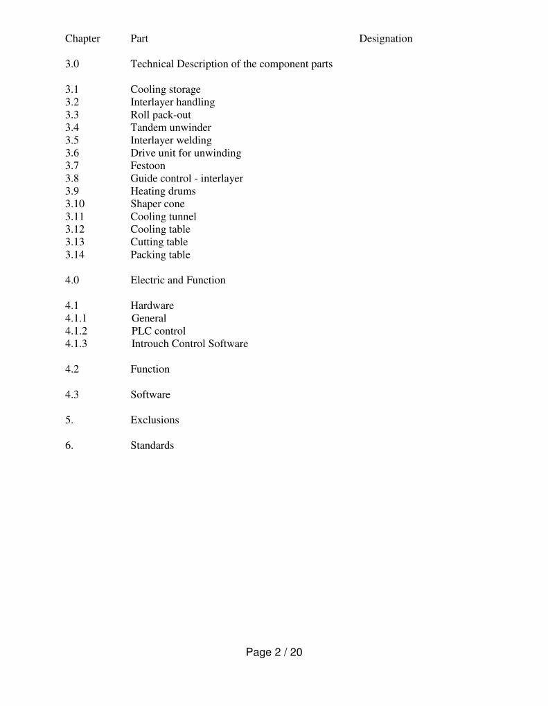
Chapter Part Designation
3.0 Technical Description of the component parts
3.1 Cooling storage
3.2 Interlayer handling
3.3 Roll pack-out
3.4 Tandem unwinder
3.5 Interlayer welding
3.6 Drive unit for unwinding
3.7 Festoon
3.8 Guide control - interlayer
3.9 Heating drums
3.10 Shaper cone
3.11 Cooling tunnel
3.12 Cooling table
3.13 Cutting table
3.14 Packing table
4.0 Electric and Function
4.1 Hardware
4.1.1 General
4.1.2 PLC control
4.1.3 Introuch Control Software
4.2 Function
4.3 Software
5. Exclusions
6. Standards
Page 3 / 20
Du Pont Deutschland
Du Pont de Nemours (Deutschland) GmbH Werk Uentrop Frielinghauser Str. 5 D-59071 Hamm �
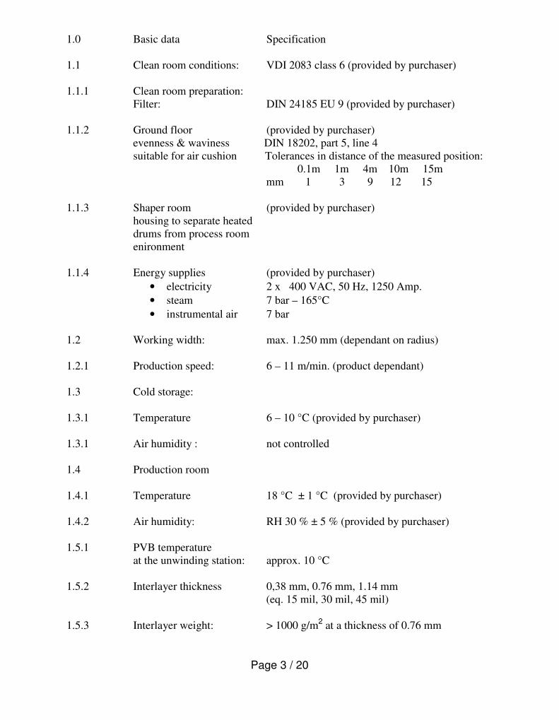
1.0 Basic data Specification
1.1 Clean room conditions: VDI 2083 class 6 (provided by purchaser)
1.1.1 Clean room preparation:
Filter: DIN 24185 EU 9 (provided by purchaser)
1.1.2 Ground floor (provided by purchaser)
evenness & waviness DIN 18202, part 5, line 4
suitable for air cushion Tolerances in distance of the measured position:
0.1m 1m 4m 10m 15m
mm 1 3 9 12 15
1.1.3 Shaper room (provided by purchaser)
housing to separate heated
drums from process room
enironment
1.1.4 Energy supplies (provided by purchaser)
• electricity 2 x 400 VAC, 50 Hz, 1250 Amp.
• steam 7 bar – 165°C
• instrumental air 7 bar
1.2 Working width: max. 1.250 mm (dependant on radius)
1.2.1 Production speed: 6 – 11 m/min. (product dependant)
1.3 Cold storage:
1.3.1 Temperature 6 – 10 °C (provided by purchaser)
1.3.1 Air humidity : not controlled
1.4 Production room
1.4.1 Temperature 18 °C ± 1 °C (provided by purchaser)
1.4.2 Air humidity: RH 30 % ± 5 % (provided by purchaser)
1.5.1 PVB temperature
at the unwinding station: approx. 10 °C
1.5.2 Interlayer thickness 0,38 mm, 0.76 mm, 1.14 mm
(eq. 15 mil, 30 mil, 45 mil)
1.5.3 Interlayer weight: > 1000 g/m2 at a thickness of 0.76 mm
Page 4 / 20
Du Pont Deutschland
Du Pont de Nemours (Deutschland) GmbH Werk Uentrop Frielinghauser Str. 5 D-59071 Hamm �
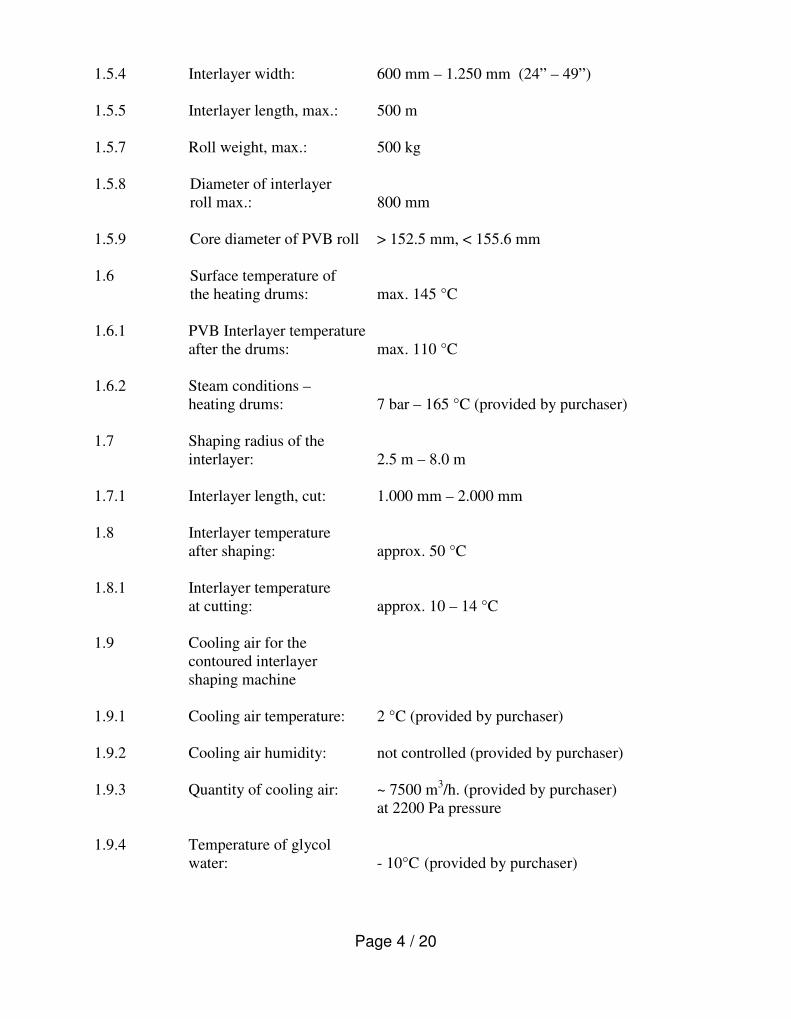
1.5.4 Interlayer width: 600 mm – 1.250 mm (24” – 49”)
1.5.5 Interlayer length, max.: 500 m
1.5.7 Roll weight, max.: 500 kg
1.5.8 Diameter of interlayer
roll max.: 800 mm
1.5.9 Core diameter of PVB roll > 152.5 mm, < 155.6 mm
1.6 Surface temperature of
the heating drums: max. 145 °C
1.6.1 PVB Interlayer temperature
after the drums: max. 110 °C
1.6.2 Steam conditions –
heating drums: 7 bar – 165 °C (provided by purchaser)
1.7 Shaping radius of the
interlayer: 2.5 m – 8.0 m
1.7.1 Interlayer length, cut: 1.000 mm – 2.000 mm
1.8 Interlayer temperature
after shaping: approx. 50 °C
1.8.1 Interlayer temperature
at cutting: approx. 10 – 14 °C
1.9 Cooling air for the
contoured interlayer
shaping machine
1.9.1 Cooling air temperature: 2 °C (provided by purchaser)
1.9.2 Cooling air humidity: not controlled (provided by purchaser)
1.9.3 Quantity of cooling air: ~ 7500 m3/h. (provided by purchaser)
at 2200 Pa pressure
1.9.4 Temperature of glycol
water: - 10°C (provided by purchaser)
Page 5 / 20
Du Pont Deutschland
Du Pont de Nemours (Deutschland) GmbH Werk Uentrop Frielinghauser Str. 5 D-59071 Hamm �
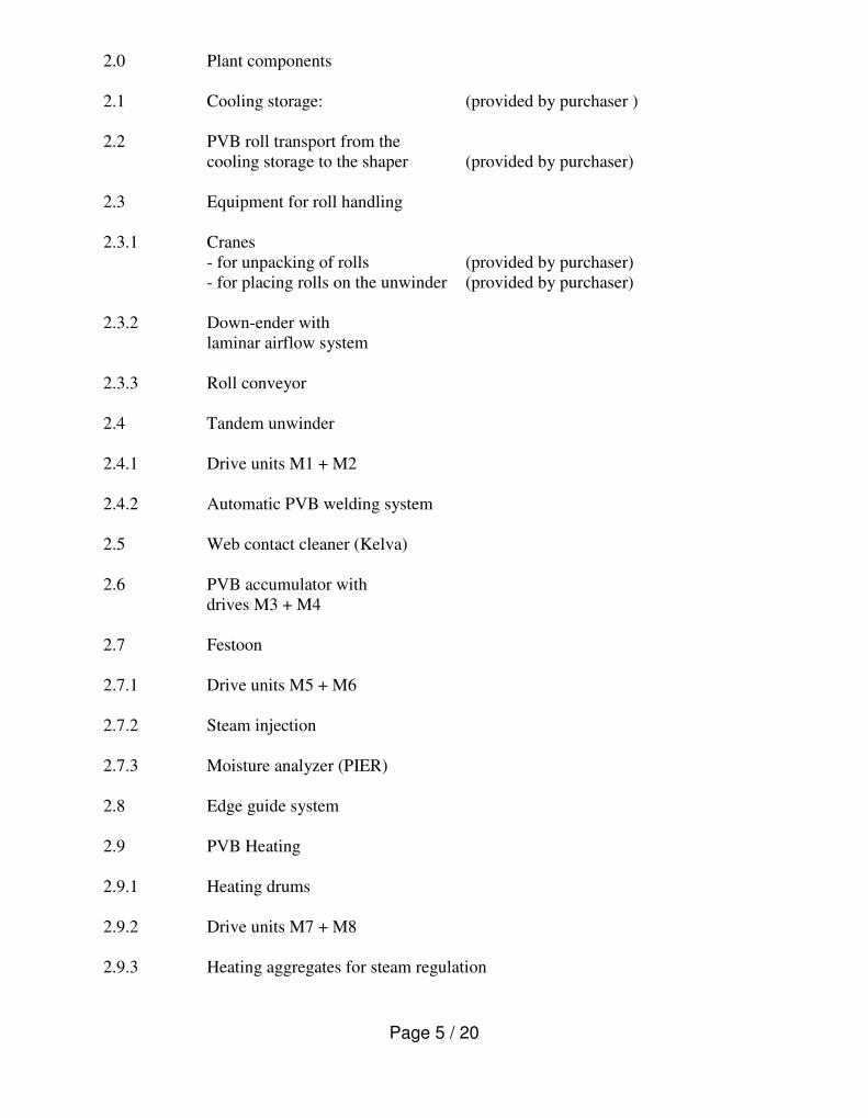
2.0 Plant components
2.1 Cooling storage: (provided by purchaser )
2.2 PVB roll transport from the
cooling storage to the shaper (provided by purchaser)
2.3 Equipment for roll handling
2.3.1 Cranes
- for unpacking of rolls (provided by purchaser)
- for placing rolls on the unwinder (provided by purchaser)
2.3.2 Down-ender with
laminar airflow system
2.3.3 Roll conveyor
2.4 Tandem unwinder
2.4.1 Drive units M1 + M2
2.4.2 Automatic PVB welding system
2.5 Web contact cleaner (Kelva)
2.6 PVB accumulator with
drives M3 + M4
2.7 Festoon
2.7.1 Drive units M5 + M6
2.7.2 Steam injection
2.7.3 Moisture analyzer (PIER)
2.8 Edge guide system
2.9 PVB Heating
2.9.1 Heating drums
2.9.2 Drive units M7 + M8
2.9.3 Heating aggregates for steam regulation

Page 6 / 20
Du Pont Deutschland
Du Pont de Nemours (Deutschland) GmbH Werk Uentrop Frielinghauser Str. 5 D-59071 Hamm �
2.10 Shaper
2.10.1 Cone with automatic adjustment for radius change
2.10.2 Drive unit M9
2.10.3 Air nozzle hood with automatic adjustment
2.11 Cooling equipment
2.11.1 Cooling tunnels #1 + #2
2.11.2 Drive unit M10
2.11.2 Cooling table with air cushion for
positioning of cooling table
2.11.3 Drive unit M11
2.11.4 Edge guide control on cooling table
2.12 Cutting table with air cushion for
positioning of table
2.12.1 2 buffer moulds
2.12.2 Drive unit M12 for control of cutting length
2.12.3 Cutting knife
2.12.4 Belt conveyor for sheet transport
2.13. Equipment for product handling
2.13.1 3 packing tables with conveyor system
2.13.2 Several tables for PVB inspection and handling
2.13.3 Heat sealer
2.13.4 Handover station
2.13.5 Left-over cabinets

Page 7 / 20
Du Pont Deutschland
Du Pont de Nemours (Deutschland) GmbH Werk Uentrop Frielinghauser Str. 5 D-59071 Hamm �
Equipment lay-out:
Page 8 / 20
Du Pont Deutschland
Du Pont de Nemours (Deutschland) GmbH Werk Uentrop Frielinghauser Str. 5 D-59071 Hamm �
3.0 Technical description of the main components
3.1 Cold storage (provided by purchaser)
The master roll packages are stored at 6 - 10 °C in the refrigerated warehouse.
3.2 Interlayer transport & handling (provided by purchaser)
The rolls scheduled for production will be placed in front of the down-ender.
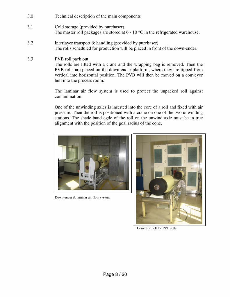
3.3 PVB roll pack out
The rolls are lifted with a crane and the wrapping bag is removed. Then the
PVB rolls are placed on the down-ender platform, where they are tipped from
vertical into horizontal position. The PVB will then be moved on a conveyor
belt into the process room.
The laminar air flow system is used to protect the unpacked roll against
contamination.
One of the unwinding axles is inserted into the core of a roll and fixed with air
pressure. Then the roll is positioned with a crane on one of the two unwinding
stations. The shade-band egde of the roll on the unwind axle must be in true
alignment with the position of the goal radius of the cone.
Down-ender & laminar air flow system
Conveyor belt for PVB rolls
Page 9 / 20
Du Pont Deutschland
Du Pont de Nemours (Deutschland) GmbH Werk Uentrop Frielinghauser Str. 5 D-59071 Hamm �
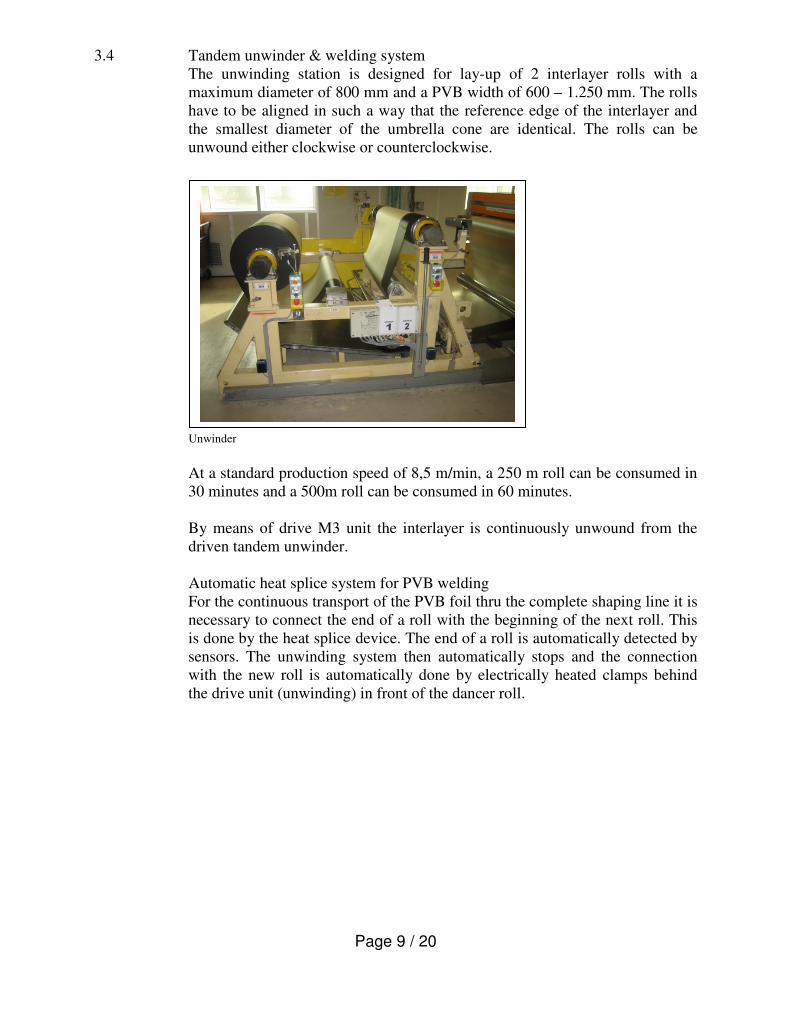
3.4 Tandem unwinder & welding system
The unwinding station is designed for lay-up of 2 interlayer rolls with a
maximum diameter of 800 mm and a PVB width of 600 – 1.250 mm. The rolls
have to be aligned in such a way that the reference edge of the interlayer and
the smallest diameter of the umbrella cone are identical. The rolls can be
unwound either clockwise or counterclockwise.
Unwinder
At a standard production speed of 8,5 m/min, a 250 m roll can be consumed in
30 minutes and a 500m roll can be consumed in 60 minutes.
By means of drive M3 unit the interlayer is continuously unwound from the
driven tandem unwinder.
Automatic heat splice system for PVB welding
For the continuous transport of the PVB foil thru the complete shaping line it is
necessary to connect the end of a roll with the beginning of the next roll. This
is done by the heat splice device. The end of a roll is automatically detected by
sensors. The unwinding system then automatically stops and the connection
with the new roll is automatically done by electrically heated clamps behind
the drive unit (unwinding) in front of the dancer roll.
Page 10 / 20
Du Pont Deutschland
Du Pont de Nemours (Deutschland) GmbH Werk Uentrop Frielinghauser Str. 5 D-59071 Hamm �
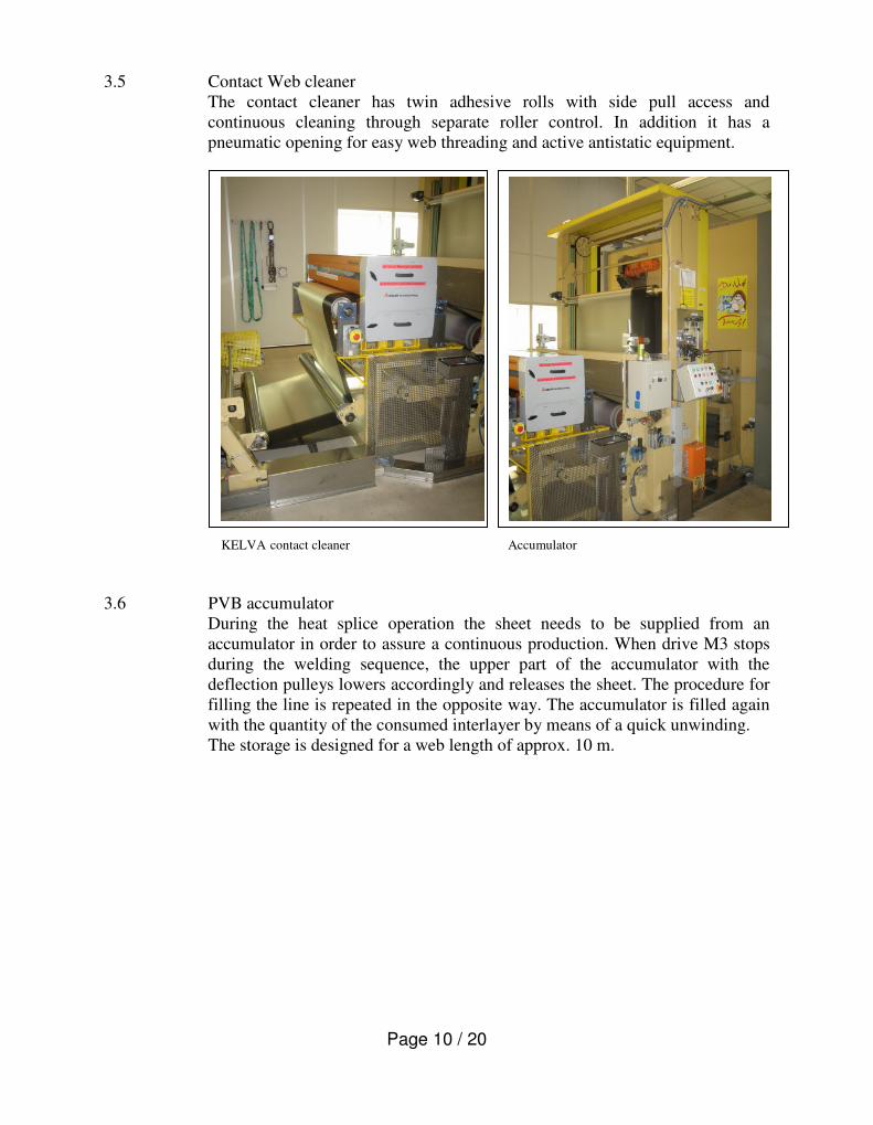
3.5 Contact Web cleaner
The contact cleaner has twin adhesive rolls with side pull access and
continuous cleaning through separate roller control. In addition it has a
pneumatic opening for easy web threading and active antistatic equipment.
KELVA contact cleaner Accumulator
3.6 PVB accumulator
During the heat splice operation the sheet needs to be supplied from an
accumulator in order to assure a continuous production. When drive M3 stops
during the welding sequence, the upper part of the accumulator with the
deflection pulleys lowers accordingly and releases the sheet. The procedure for
filling the line is repeated in the opposite way. The accumulator is filled again
with the quantity of the consumed interlayer by means of a quick unwinding.
The storage is designed for a web length of approx. 10 m.
Page 11 / 20
Du Pont Deutschland
Du Pont de Nemours (Deutschland) GmbH Werk Uentrop Frielinghauser Str. 5 D-59071 Hamm �
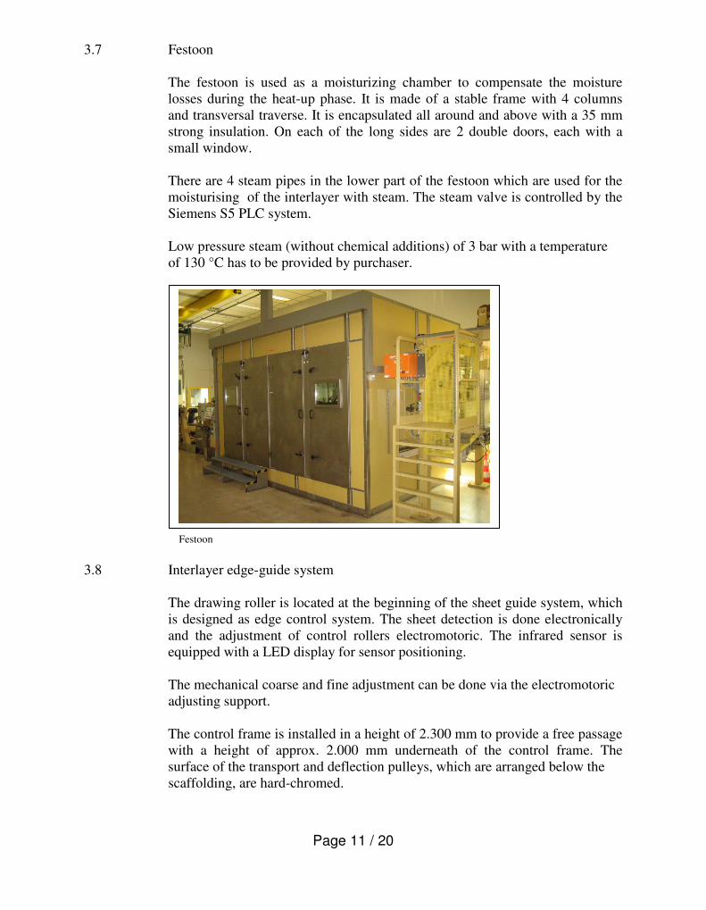
3.7 Festoon
The festoon is used as a moisturizing chamber to compensate the moisture
losses during the heat-up phase. It is made of a stable frame with 4 columns
and transversal traverse. It is encapsulated all around and above with a 35 mm
strong insulation. On each of the long sides are 2 double doors, each with a
small window.
There are 4 steam pipes in the lower part of the festoon which are used for the
moisturising of the interlayer with steam. The steam valve is controlled by the
Siemens S5 PLC system.
Low pressure steam (without chemical additions) of 3 bar with a temperature
of 130 °C has to be provided by purchaser.
Festoon
3.8 Interlayer edge-guide system
The drawing roller is located at the beginning of the sheet guide system, which
is designed as edge control system. The sheet detection is done electronically
and the adjustment of control rollers electromotoric. The infrared sensor is
equipped with a LED display for sensor positioning.
The mechanical coarse and fine adjustment can be done via the electromotoric
adjusting support.
The control frame is installed in a height of 2.300 mm to provide a free passage
with a height of approx. 2.000 mm underneath of the control frame. The
surface of the transport and deflection pulleys, which are arranged below the
scaffolding, are hard-chromed.

Page 12 / 20
Du Pont Deutschland
Du Pont de Nemours (Deutschland) GmbH Werk Uentrop Frielinghauser Str. 5 D-59071 Hamm �
Edge-Guide system
3.9 Heating drums
The drums are heated via saturated steam, which is provided by the customer.
The drums are designed as cylindrical single shell construction.The surfaces
are made with an FEP covering.
There are 2 main drums with 900 mm diameter and 4 satellite drums of 210
mm diameter. Heated are only that main drum and the two small satellite
drums, which are in the closest distance to the shaper cone. All others are kept
cold.
The inlet and outlet of the heating medium is done unilateral with screwed-in
thread and rotary transmission leadthrough.
Only the last main drum (#39 in front of the cone) and the 2 rubber coated
satellite drums need to be heated for a commercial production of up to 11
m/min line speed.
The big rollers with a diameter of 900 mm have their own drive, the rollers
with a diameter of 210 mm are coupled mechanically with the main rollers.

Page 13 / 20
Du Pont Deutschland
Du Pont de Nemours (Deutschland) GmbH Werk Uentrop Frielinghauser Str. 5 D-59071 Hamm �
3.10 Shaper cone with cooling hood
In front of the cone there is another silicone rubber coated heat drum (∅ 210
mm) accompanied by an EPDM coated nip roller as well as a pivoting roller.
The nip roller is used to fix the sheet, so that the tension caused by the cone can
stress only a defined portion of the PVB. In addition, the friction by the nip
roller helps to minimize the sheet neck-down during shaping. The rollers are
connected with the main drive via gear belt and gear box.
The pivoting roller is used at production radii > 4.5 m to remove wrinkles in
the sheet, which can be generated due to the cone geometry.
The shaper cone consists of 60 adjustable spokes to allow modification of the
shaping radius. The adjustment of the spokes and the hood can be done during
production via gear motor with brake and absolute shaft encoder. In addition, it
is possible to increase/decrease the cone speed via PLC independent from the
line speed.
The cone is driven via motor and tooth belt. Adjustements of the cone pitch
and the hood with the air nozzles can be done while the line is running. There
is an interlock via PLC and limit swich to avoid collosion between the cone
and the hood during adjustments.
The cooling hood is equipped with nozzles for the feed-and exhaust air lines of
the cooling air. Behind the umbrella a metal through is arranged with following
air cushion table for transfer to the pulling head before the cooling table.
Shaper cone Cooling tunnel
Page 14 / 20
Du Pont Deutschland
Du Pont de Nemours (Deutschland) GmbH Werk Uentrop Frielinghauser Str. 5 D-59071 Hamm �
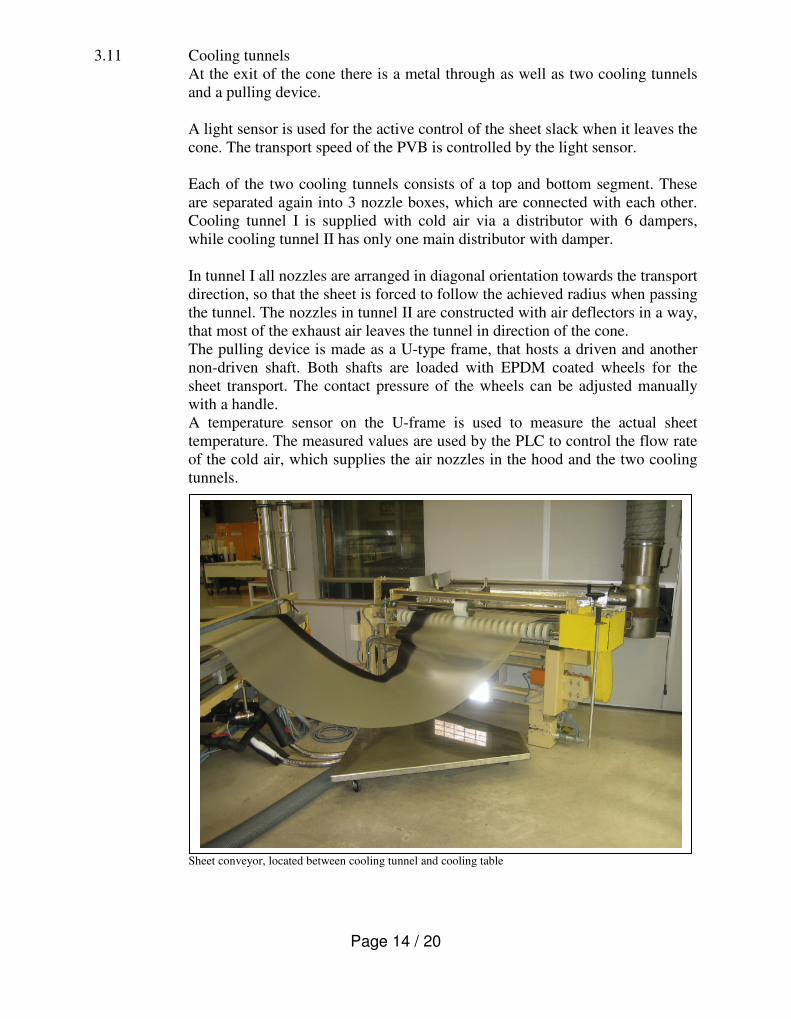
3.11 Cooling tunnels
At the exit of the cone there is a metal through as well as two cooling tunnels
and a pulling device.
A light sensor is used for the active control of the sheet slack when it leaves the
cone. The transport speed of the PVB is controlled by the light sensor.
Each of the two cooling tunnels consists of a top and bottom segment. These
are separated again into 3 nozzle boxes, which are connected with each other.
Cooling tunnel I is supplied with cold air via a distributor with 6 dampers,
while cooling tunnel II has only one main distributor with damper.
In tunnel I all nozzles are arranged in diagonal orientation towards the transport
direction, so that the sheet is forced to follow the achieved radius when passing
the tunnel. The nozzles in tunnel II are constructed with air deflectors in a way,
that most of the exhaust air leaves the tunnel in direction of the cone.
The pulling device is made as a U-type frame, that hosts a driven and another
non-driven shaft. Both shafts are loaded with EPDM coated wheels for the
sheet transport. The contact pressure of the wheels can be adjusted manually
with a handle.
A temperature sensor on the U-frame is used to measure the actual sheet
temperature. The measured values are used by the PLC to control the flow rate
of the cold air, which supplies the air nozzles in the hood and the two cooling
tunnels.
Sheet conveyor, located between cooling tunnel and cooling table
Page 15 / 20
Du Pont Deutschland
Du Pont de Nemours (Deutschland) GmbH Werk Uentrop Frielinghauser Str. 5 D-59071 Hamm �
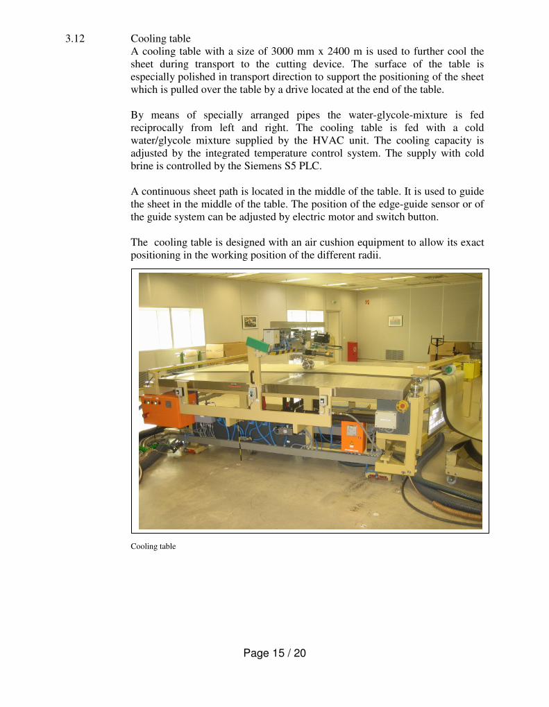
3.12 Cooling table
A cooling table with a size of 3000 mm x 2400 m is used to further cool the
sheet during transport to the cutting device. The surface of the table is
especially polished in transport direction to support the positioning of the sheet
which is pulled over the table by a drive located at the end of the table.
By means of specially arranged pipes the water-glycole-mixture is fed
reciprocally from left and right. The cooling table is fed with a cold
water/glycole mixture supplied by the HVAC unit. The cooling capacity is
adjusted by the integrated temperature control system. The supply with cold
brine is controlled by the Siemens S5 PLC.
A continuous sheet path is located in the middle of the table. It is used to guide
the sheet in the middle of the table. The position of the edge-guide sensor or of
the guide system can be adjusted by electric motor and switch button.
The cooling table is designed with an air cushion equipment to allow its exact
positioning in the working position of the different radii.
Cooling table

Page 16 / 20
Du Pont Deutschland
Du Pont de Nemours (Deutschland) GmbH Werk Uentrop Frielinghauser Str. 5 D-59071 Hamm �
3.13 Cutting table
There is a moveable buffer hutch with stainless steel plate located between
cooling table and cutting table to allow storage of the incoming sheet, when the
PVB transport on the cutting table is stopped during the cutting operation.
The adjustable cutting device is located in the middle of the table. In front of
the cutting wheel the table is covered with a polished stainless steel plate. A
moisture sensor and a temperature sensor are installed for control of the actual
production parameter. A driven pair of EPDM coated rollers is used to move
the sheet towards the cutter. The sheet transport is controlled by the Siemens
S5 PLC system, which helps to position the sheet so that is cut very accurately
to the defined length.
Cutting table

Page 17 / 20
Du Pont Deutschland
Du Pont de Nemours (Deutschland) GmbH Werk Uentrop Frielinghauser Str. 5 D-59071 Hamm �
4.0 Electric and Function
4.1 Hardware
4.1.1 General
The power supply (provided by purchaser) is 400 VAC, 50 Hz.
Following voltages will be generated within the plant.
230 VAC, 50 Hz for
� S5-supply
� control voltage
24 VDC = direct current for – input/output level S 5
� control voltage
� supply of measuring devices
The production area is supplied with electrical energy via MCC-28-3A. All
cables exit MCC-28-3A (see picture) heading towards the HVAC equipment
are subject of this sales agreement. The MCC must be provided by the
purchaser.
MCC-28-3A
Page 18 / 20
Du Pont Deutschland
Du Pont de Nemours (Deutschland) GmbH Werk Uentrop Frielinghauser Str. 5 D-59071 Hamm �
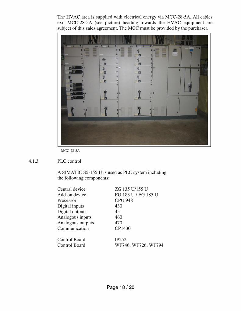
The HVAC area is supplied with electrical energy via MCC-28-5A. All cables
exit MCC-28-5A (see picture) heading towards the HVAC equipment are
subject of this sales agreement. The MCC must be provided by the purchaser.
MCC-28-5A
4.1.3 PLC control
A SIMATIC S5-155 U is used as PLC system including
the following components:
Central device ZG 135 U/155 U
Add-on device EG 183 U / EG 185 U
Processor CPU 948
Digital inputs 430
Digital outputs 451
Analogous inputs 460
Analogous outputs 470
Communication CP1430
Control Board IP252
Control Board WF746, WF726, WF794
Page 19 / 20
Du Pont Deutschland
Du Pont de Nemours (Deutschland) GmbH Werk Uentrop Frielinghauser Str. 5 D-59071 Hamm �
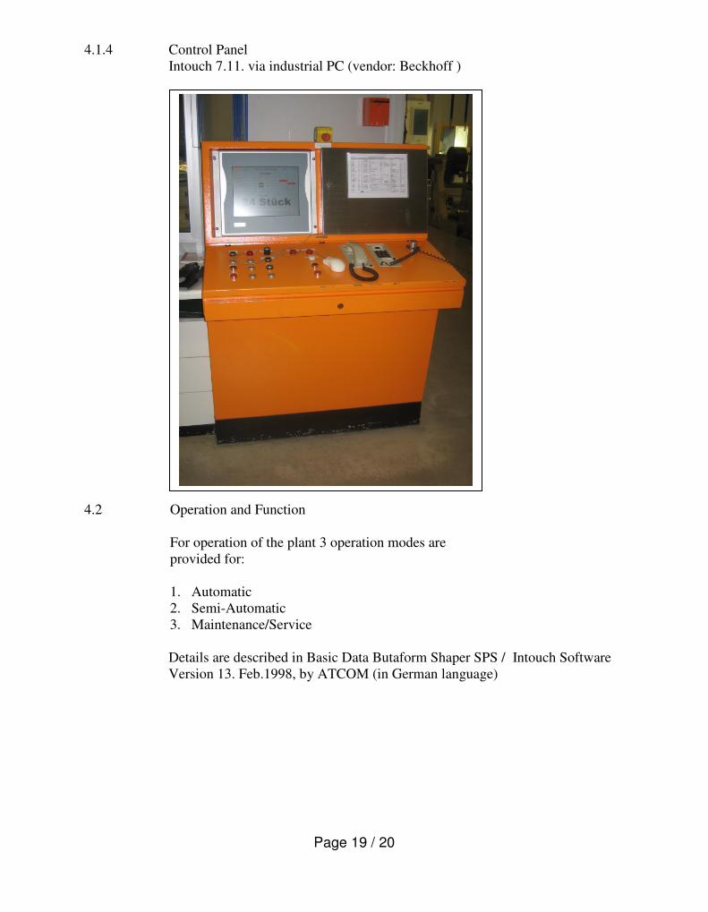
4.1.4 Control Panel
Intouch 7.11. via industrial PC (vendor: Beckhoff )
4.2 Operation and Function
For operation of the plant 3 operation modes are
provided for:
1. Automatic
2. Semi-Automatic
3. Maintenance/Service
Details are described in Basic Data Butaform Shaper SPS / Intouch Software
Version 13. Feb.1998, by ATCOM (in German language)
Page 20 / 20
Du Pont Deutschland
Du Pont de Nemours (Deutschland) GmbH Werk Uentrop Frielinghauser Str. 5 D-59071 Hamm �
4.3 Software
The whole program was described in FUP and in AWL, as far as possible.
Individual functions like e.g. selection of kinds of operation, processing of
faults got own PB’s each. For each plant segment one or more PB’s were
provided for, acc. to the complexity of the machine part.
The goal was to achieve an optimum of clearness in the programme structure.
• All programming segments have a clear text comment (in German).
• Inputs/outputs/markers/times/counters/ data words are labelled with clear
text (in German).
5. Exclusions
The following parts are not subject of the sales agreement:
• Parts of the building like walls, ceiling, doors
• Metal frames, which are used to support the static of the building
(althought they may be used to carry cables, piping, etc.)
• Lamps, lighting equipment
• HVAC units
• Motor control center (MCC)s
• Cable trays, racks
• Cranes
• Balancer system for heat sealers
• Equipment for fire protection
• Operating materials (refrigerants, lubricants)
Standards
Design and manufacture are based on the metric system, DIN, ISO, and electrical equipment
VDE.
All necessary direct safety devices at the machines correspond to the legal regulations.
All indirect safety devices as fences, closings, safety railings have to be provided by the
purchaser according to the official regulations at own expense.


![Du Pont[1]](https://static.fdocuments.net/doc/165x107/55920a3c1a28ab35178b46dd/du-pont1.jpg)


