DTI FILE COPY - Defense Technical Information Center · DTI o FILE COPY REPAIR, EVALUATION,...
118
DTI o FILE COPY REPAIR, EVALUATION, MAINTENANCE, AND REHABILITATION RESEARCH PROGRAM of Engieer TECHNICAL REPORT REMR-OM-7 AD-A227 198 INSPECTION AND RATING OF MITER LOCK GATES by Lowell Greimann I= SJames Stecker Kevin Rens ENGINEERING RESEARCH INSTITUTE Iowa State University Ames, Iowa 50011 -COSI 0,1 ELECTE O 0CT 0 31990 August 1990 Final Report Approved For Public Release; Distribution Unlimited Prepared for DEPARTMENT OF THE ARMY US Army Corps of Engineers Washington, DC 20314-1000 Under Civil Works Research Work Unit 32280 Monitored by Engineering and Materials Division US Army Construction Engineering Research Laboratory P.O. Box 4005, Champaign, Illinois 61824-4005 90 Ai 0C
Transcript of DTI FILE COPY - Defense Technical Information Center · DTI o FILE COPY REPAIR, EVALUATION,...

DTI o FILE COPYREPAIR, EVALUATION, MAINTENANCE, AND
REHABILITATION RESEARCH PROGRAM
of Engieer TECHNICAL REPORT REMR-OM-7
AD-A227 198INSPECTION AND RATING OF
MITER LOCK GATES
by
Lowell GreimannI= SJames SteckerKevin Rens
ENGINEERING RESEARCH INSTITUTEIowa State UniversityAmes, Iowa 50011
-COSI 0,1
ELECTEO 0CT 0 31990
August 1990Final Report
Approved For Public Release; Distribution Unlimited
Prepared for DEPARTMENT OF THE ARMYUS Army Corps of EngineersWashington, DC 20314-1000
Under Civil Works Research Work Unit 32280
Monitored by Engineering and Materials DivisionUS Army Construction Engineering Research Laboratory
P.O. Box 4005, Champaign, Illinois 61824-4005
90 Ai 0C
The following two letters used as part of the number designating technical reports of research published under the Repair, Evaluation,
Maintenance, and Rehabilitation (REMR) Research Program identify the problem area under which the report was prepared:
Problem Area Problem Area
CS Concrete and Steel Structures EM Electrical and Mechanical
GT Geotechnical El Environmental Impacts
HY Hydraulics OM Operations Management
CO Coastal
Destroy this report when no longer needed. Do not returnit to the originator.
The findings in this report are not to be construed as an officialDepartment of the Army position unless so designated
by other authorized documents.
The contents of this report are not to be used foradvertising, publication, or promotional purposes.Citation of trade names does not constitute anofficial endorsement or approval of the use of
such commercial products.
COVER PHOTOS:
TOP - Miter lock gate at Old Hickory Lock and Dam on the Cumberland River in the Nashville District.
BOTTOM - Aerial view of Mississippi River Lock and Dam No. 16 in the Rock Island District.

Fom, AooverdREPORT DOCUMENTATION PAGE I OM No. 0704-018
"k repnotng bd foe hi m on 810d tO evelege I "o t Nel in cluding the tin fo0 reviewln itVucticift tea.cnng groit date ~vfce,.~~uie~~~eng~ In Ianln th aaneed o mstn . resviw- the collection of Ilnlwmaion. Send commients regrdingthe bwdee estimate - " -&ty o it"..oe of this980witiq ownels" . I - g 1 ugsin for 1111g h burden. 10 Wadugngton headquarter,11 SerVKIce W000ectort .o Ifrma'Wtin OW erain nd RapOrU.IllIS leffa~n(ami h way. Suite 1204. Atlkng O". VA 2W2-43 0). ndt the Office of Management and ludget. Poo4rwOrs Kductlon ProIeto (704-0t).ISM, Wlg ,on. DC 20.
i. AGENCY USE ONLY (Leave blank) 2. REPORT DATE 1 3. REPORT TYPE AND DATES COVERED
August 1990 Final4. TITLE AND SUBTITLE S. FUNDING NUMBERS
Inspection and Rating of Miter Lock Gates Research Unit: 32280
6. AUTHOR(S)Greimann, Lowell; Stecker, James; and Rens, Kevin
7. PERFORMING ORGANIZATION NAME(S) AND ADDRESS(ES) B. PERFORMING ORGANIZATIONREPORT NUMBER
Engineering Research InstituteIowa State UniversityAmes, IA 50011
9. SPONSOAIING/MONITORING AGENCY NAME() AND ADDRESS(ES) 10. SPONSORING/ MONITORINGAGENCY REPORT NUMBER
Engineering and Materials Division
US Army Construction Engineering Research Laboratory Technical ReportP.O. Box 4005 REMR-OM-7Champaign, IL 61824-4005
it. SUPPLiMENTARY NOTES A report of the Operations Management problem area of the Repair,Evaluation, Maintenance, and Rehabilitation (REMR) Research Program. Available fronNational Technical Information Service, 5285 Port Royal Road, Springfield, VA 22161.
12a. DISTRIBUTION/ AVAILABILITY STATEMENT 12b. DISTRIBUTION CODEApproved for public release; distribution unlimited.
13. ABSTRACT (Maximum 200 words)
' The objectives of this work are:(Il) to develop an inspection and ratingsystem that uniformly and consistently describes the current condition ofmiter lock gate structuresand (2) to develop guidelines for the maintenanceand repair of these structures. Only the first objective is addressed in thisreport.
This report gives a general description of the current inspection andrating system. This includes the definition of a condition index and adescription of miter lock gate distresses. A detailed description of theinspection process follows. Once the inspection data have been gathered, theyare filed on a computer disk through a microcomputer program. The programthen computes the structural and functional condition indexes for miter lockgates. r-
14 Su-ICT TERMS 1. NUMBER OF PAGESmiter lock gate inspection 105maintenance 16. PRICE CODErepair
17. SECURITY CLASSIFICATION Is. SECURITY CLASSIFICATION I. SECURITY CLASSIFICATION 20. LIMIATION OF ABSTRACTOF REPORT OF THIS PAGE OF ABSTRACTUNCLASSIFIED UNCLASSIFIED UNCLASSIFIED SAR
NN '0,40 01 ?O SOO Standard Form 298 (Rev. 2-69)
Prembr by ANSI Sid 13911

PREFACE
This study was authorized by Headquarters, US Army Corps of Engineers
(HQUSACE), under Civil Works Research Unit 32280, "Development of Uniform
Evaluation for Procedures/Condition Index for Deteriorated Structures and
Equipment," for which Dr. Anthony M. Kao was Principal Investigator. This
work unit was part of the Operations Maintenance Problem Area of the Repair,
Evaluation, Maintenance, and Rehabilitation (REMR) Research Program sponsored
by HQUSACE. Mr. Jim Crews (CECW-OO) was the REMR Technical Monitor.
Mr. Jesse A. Pfeiffer, Jr., (CERD-C) was the REMR Coordinator at the
Directorate of Research and Development, HQUSACE; Mr. Jim Crews and Dr. Tony
C. Liu (CEEC-ED) served as the REMR Overview Committee; Mr. William F.
McCleese (CEWES-SC-A), US Army Engineer Waterways Experiment Station, was the
REMR Program Manager; and Dr. Kao was also the Problem Area Leader for the
Operations Management Problem Area.
The study was performed by the College of Engineering, Iowa State
University, under contract to the US Army Construction Engineering Research
Laboratory (USACERL). Principal Investigators for ISU were Professors Lowell
Greimann and James Stecker. Kevin Rens was the research assistant.
The study was conducted under the general supervision of Dr. R.
Quattrone, Chief of Engineering and Materials Division (EM), USACERL, and
under the direct supervision of Dr. Anthony M. Kao, EM, who was the
Contracting Officer's Representative. The technical editor was Patrick
O'Hayer, Information Management Office.
COL Everett R. Thomas was the Commander and Director of USACERL and
Dr. L. R. Shaffer was Technical Director.
* -ipson For
-1 IS GRA&II-TIC TAB
Unannoumced IJustification
By
Distribution/. //
Availability CodesAvail and/or
Dist Spcial

CONTENTS
PagePREFACE 1LIST OF TABLES AND FIGURES...............................3
PART I: INTRODUCTION..................................4Background.........................................4Objectives and Scope...............................4Mode of Technology Transfer.............................5overview.......................................5Lock Miter Gate Component identification...............9
PART II: FIELD INSPECTION...............................17Overview of the Inspection Form......................18
PART III: STRUCTURAL CONDTTION INDEX........................44Structural Analysis................................44Loads.........................................45Component Condition Index for Each Load Case...............47Corrosion Modified Structural Condition Index...............53
PART IV: FUNCTIONAL CONDITION INDEX..........................55Distress Descriptions and X max..........................58Distress Code 1: Top Anchorage Movement...................59Distress Code 2: Elevation Change......................62Distress Code 3: Miter Offset......................65Distress Code 4: Bearing Gaps......................69Distress Code 5: Downstream Movement.....................73Distress Code 6: Cracks.............................75Distress Code 7: Leaks and Boils.....................77Distress Code 8: Dents. .......................... 80Distress Code 9: Noise and Vibration.....................82Distress Code 10: Corrosion.........................83Multiple Distresses..................................89Field Testing.....................................90
PART V: SUMMARY AND CONCLUSIONS.........................102Summary.......................................102Conclusions and Recommendations........................103
REFERENCES........................................104
APPENDIX: SAMPLE COMPUTER RESULTS.......................Al
2
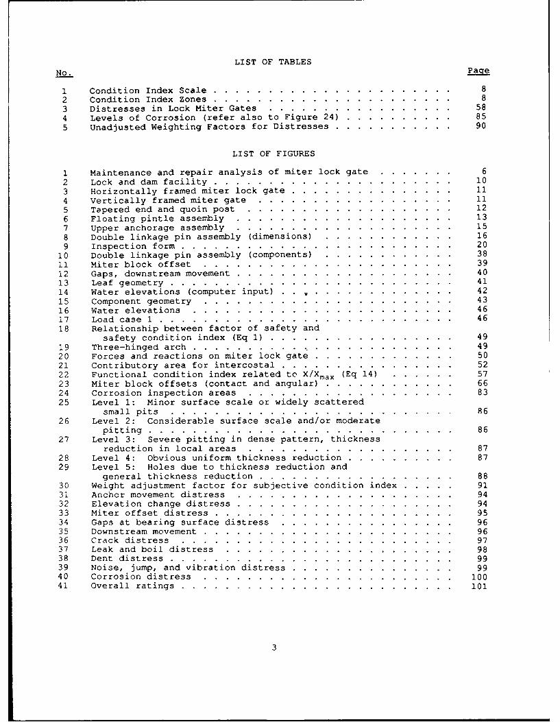
LIST OF TABLES
No. Page
1 Condition Index Scale ............ ...................... 82 Condition Index Zones ............ ...................... 83 Distresses in Lock Miter Gates ......................... 584 Levels of Corrosion (refer also to Figure 24) .. .......... 855 Unadjusted Weighting Factors for Distresses .. ........... . 90
LIST OF FIGURES
1 Maintenance and repair analysis of miter lock gate .... ....... 62 Lock and dam facility .......... .. ...................... 103 Horizontally framed miter lock gate ..... ............... . 114 Vertically framed miter gate ...... .................. 115 Tapered end and quoin post ...... ................... . 126 Floating pintle assembly ....... .................... 137 Upper anchorage assembly ......................... 158 Double linkage pin assembly (dimensions) ... ............ 169 Inspection form .................. .......................... 20
10 Double linkage pin assembly (components) ... ............ 3811 Miter block offset ......... ....................... 3912 Gaps, downstream movement ....... .................... 4013 Leaf geometry .......... .......................... 4114 Water elevations (computer input) ..... ............. . 4215 Component geometry ......... ....................... 4316 Water elevations ......... ........................ 4617 Load case 1 ...... ........................... 4618 Relationship between factor of safety and
safety condition index (Eq 1) ......... ................. 4919 Three-hinged arch ... .............. ............... 4920 Forces and reactions on miter lock gate .... ............. .. 5021 Contributory area for intercostal ..... ................ . 5222 Functional condition index related to X/Xmax (Eq 14) ...... 5723 Miter block offsets (contact and angular) ... ............ .. 6624 Corrosion inspection areas ...... ................... 8325 Level 1: Minor surface scale or widely scattered
small pits .......... .......................... 8626 Level 2: Considerable surface scale and/or moderate
pitting ............ ............................ 8627 Level 3: Severe pitting in dense pattern, thickness
reduction in local areas ... ................... 8728 Level 4: Obvious uniform thickness reduction. ............ ... 8729 Level 5: Holes due to thickness reduction and
general thickness reduction ...... .................. . 8830 Weight adjustment factor for subjective condition index ..... . 9131 Anchor movement distress ....... .................... 9432 Elevation change distress ....... .................... 9433 Miter offset distress ...................... 9534 Gaps at bearing surface distress ..... ................ 9635 Downstream movement ......... ....................... . 9636 Crack distress .......... ......................... 9737 Leak and boil distress ........ ..................... 9838 Dent distress .............. .......................... . 9939 Noise, jump, and vibration distress ..... ............... . 9940 Corrosion distress ......... ....................... 10041 Overall ratings .......... ......................... 101
3

INSPECTION AND RATING OF MITER LOCK GATES
PART I: INTRODUCTION
Background
1. The US Army Corps of Engineers has acquired and completed a large
inventory of civilian projects over the past 100 years. For much of this time
the Corps concentrated on design and construction of new facilities, such as
locks and dams on navigable inland waterways and coastal systems, as well as
power generation. Recently the mission of the Corps has been shifting from
construction of new facilities to maintenance of existing facilities because
many existing structures are nearing the end of their design life, and fewer
opportunities for expansion of Corps projects are available. The Corps has
addressed its changing role by instituting a Repair, Evaluation, Maintenance,
and Rehabilitation (REMR) program. As this name implies, maintenance encom-
passes several stages. To some extent, each stage requires the development of
a new technology and methodology.
2. As a part of this program, the project team at Iowa State University
(ISU) performed research focusing on evaluation and repair of miter lock gate
structures in the Corps' civilian projects. Miter lock gates are an important
operating component of a lock and dam facility. If they fail to function or
function improperly, the operation of the lock is severely affected. Often,
only one lock is available at a dam site, and if it does not function, naviga-
tion along the entire river can be delayed, with subsequent large user costs.
Miter lock gates are probably the most frequent cause of lock shutdown for
repair and maintenance.
Objectives and Scope
3. The overall objectives of this work are twofold:
a. To develop a uniform procedure to describe the current conditionof miter lock gate structures.
b. To develop guidelines for the maintenance and repair of thesestructures.
The scope of this report is limited to the first objective. A complete report
summarizing work on both objectives is scheduled for later this year.
4

Mode of Technology Transfer
4. It is recommended that the inspection procedures for miter lock
gates developed in this study be incorporated into Engineer Regulation (ER)1110-2-100, "Periodic Inspection and Continuing Evaluation of Completed Civil
Works Structures."
Overview
5. The concepts presented for the maintenance management of miter lockgates rely heavily on a similar project for steel sheet pile structures
(Greimann and Stecker 1989). During that earlier work, ideas such as struc-tural and functional condition indexes, safety and serviceability, quantifi-
cation of distresses by field measurements, limiting values of distresses, andrepair and maintenance alternatives began to evolve. As these concepts were
applied to miter lock gates, several enhancements became apparent, and some
new ideas appeared.
6. The project team at ISU held many meetings with Corps personnel andcond,i-ted site visits and field investigations at many lock and dam facili-
ties, and several considerations for miter lock gates were identified. Corpsexperts conveyed their opinions on the critical components of miter lock gate
operation and repair. They suggested means of quantifying these components
and relating them to the overall condition of the miter gates. The project
team took the experts' comments and formulated them into an inspection pro-
cedure and a tentative set of rating rules. Field tests of the inspectionform and rating rules were conducted at five gate sets. At each test site,improvements to the rules and inspection process were suggested by the
experts. insofar as was possible, except for cases of conflicting expertopinion, the suggestions were incorporated into this work.
Field inspection
7. The maintenance and repair procedure is illustrated schematically inFigure 1. The process is based on a good field inspection of the miter lockgate structure. During this inspection, current physical attributes of the
systems are obtained. Data, such as the location of the gate, inspectionhistory, historical water level, and maintenance history, are recorded on thefirst two pages of the inspection form. Other inspection form pages are used
to describe some structural details such as girder cross sections, skin plate,and intercostal size. The information on these pages is used as the basis fora structural evaluation of the gate. Additional pages provide space for
several field measurements such as anchorage movements, elevation changes,
downstream movement, cracks, dents, and corrosion. These measurements areused directly to rate the condition of the gate.
L3

INSPECTION
..PC. DATA FILE ,
FUNCTIONAL CI STRUCTURAL CI
CMINED CI
SSOLUTIONS I
CONSEQUENCES AND LCCA
Figure 1. Maintenance and repair analysis of miter lock gate
8. The information collected on the inspection form is entered into a
data file through a program called MITER on a microcomputer. The programpermits file editing and handles the data for all succeeding steps.
Condition index9. The rating process is the next step. Information in the inspection
data is used in MITER to calculate a condition index (CI) for the structure.
A condition index is a numerical measure of the current state of a structure.It is part of the goal of this project to define a condition index that
uniformly and consistently describes and ranks the condition of miter lockgate structures. The condition index is primarily a planning tool, with theindex values serving as an indicator of the general condition level of the
6

structure. The index is meant to focus management attention on those struc-
tures most likely to warrant immediate repair or further evaluation. In
addition, the CI values can be used to monitor change in general condition
over time and can serve as an approximate comparison of the condition of
different structures.
10. A common CI definition for the REMR work has evolved: The REMR
condition index is a numbered scale, from 0 to 100, indicating the relative
need to perform REMR work because of functional and structural deterioration.
The condition index scale in Table 1 has been adopted. For management
purposes, the condition index scale is calibrated to group structures into
three categories or zones (Table 2).
11. Two general structural criteria for evaluating the condition index
are available: safety and serviceability. Safety relates to structures'
performance beyond normal service conditions; for example, under abnormal
conditions such as excessive load. Serviceability relates to the performance
of a structure under normal service conditions, such as, excessive leakage.
Two condition indexes were formulated to describe the structure relative to
these criteria. The first, the structural condition index, is based on a
structural analysis of the miter lock gate structure. It primarily includes
safety aspects. The second, the functional condition index, is based on field
measurements of the distresses and the opinion of experts. It includes both
safety and serviceability aspects. (Parts III and IV deal with these two
condition indexes in more detail.)
12. As the condition index zones in Table 2 indicate, one purpose of
the condition index is to draw attention to a particular problem that may
require further investigation (e.g., Zone 3). In this regard, the combined
condition index oc, simply, the condition index will be defined as follows:
Condition index = minimum of
Structural Condition Index
Functional Condition Index
if the structure has a poor condition index, the engineer is alerted and can
trace back to determine whether the caus. is a low structural or functional
condition index. Indeed, the engineer would presumably trace back through the
entire rating process and possibly conduct a more detailed field inspection or
structural analysis to establish the basic cause. Experience indicates that
major structural and mechanical problems sometimes develop without warning.
Therefore, a District should not become complacent about the condition of a
gate as a result of a favorable condition index. Experienced engineers should
be relied upon to make judgments regarding the significance of the condition
index.
7

Table 1
Condition Index Scale
Value Condition Description
85-100 Excellent--No noticeable defects, some aging or wear visible
70-84 Very Good--Only minor deterioration or defects evident
55-69 Good--Some deterioration or defects evident, function notimpaired
40-54 Fair--Moderate deterioration, function not seriously impaired
25-39 Poor--Serious deterioration in at least some portions ofstructure, function seriously impaired
10-24 Very Poor--Extensive deterioration, barely functional
0-9 Failed--General failure or failure of a major component, nolonger functional
Table 2
Condition Index Zones
Zone CI Range Action
1 70-100 Immediate action not required
2 40-69 Economic analysis of repair alternativesrecommended to determine appropriate maintenanceaction
3 0-39 Detailed evaluation required to determine theneed for repair, rehabilitation orreconstruction, safety evaluation required
8

Maintenance and repair analysis
13. After an evaluation of the current condition of the structure, the
user will want to evaluate different maintenance and repair alternatives.
This subject will be addressed in a subsequent report.
Lock Miter Gate Component Identification
14. To inspect and rate miter lock gate structures, the user must
clearly identify their components; definitions for these components are pre-
sented in the following paragraphs. Figure 2 illustrates a typical lock and
dam facility.
15. Horizontal girders are plate steel sections that span horizontally.
Their main function is to transfer load to the quoin. In the horizontally
framed miter lock gate (Figure 3), the load is transferred from the skin plate
through the horizontal girders and back into the lock wall. The bottom
horizontal girders on a horizontally framed gate does not transfer load into
tramed gate (Figure 4), two horizontal girders carry the load from the
vertical girders. The top girder then transmits the load to the lock wall.
Figure 3. Horizontally framed miter lock gate vertical girders. The top
girder then transmits the load to the lock wall. The bottom horizontal member
transfers the load directly into the sill.
16. Vertical girders are plate steel sections that span vertically to
transfer load to the horizontal girders. In the vertically framed gate
(Figure 4), the load is transferred from the skin plate through the vertical
girders to the top and bottom horizontal girder.
17. A skin plate is welded (sometimes riveted) between girders to
provide vertical stiffness to the gate leaf. The skin plate dams the water
and acts as part of the upstream flange of the girders.
18. The horizontal girders are connected vertically by several inter-
mediate diaphragms and two end diaphragms, one at the quoin end and one at the
miter end of the horizontally framed miter lock gate in Figure 3. The end
diaphragms also serve to dam the water in the tapered end section (Figure 5).
The vertically framed gate contains no diaphragms.
19. Intercostals are provided between diaphragms on the horizontally
framed gate (Figure 3) and between girders on the vertically framed gate
(Figure 4). Intercostals serve to stiffen and support the skin plate.
20. The thrust diaphragm shown in the tapered end section of Figure 5
distributes the horizontal girder reactions from the quoin block into the
girder webs.
21. The quoin block (located on the gate leaf) and the wall quoin
(located on the concrete monolith) transmit bearing forces from the gate to
the lock wall. The wall quoin has a concave surface and the quoin block has a
9
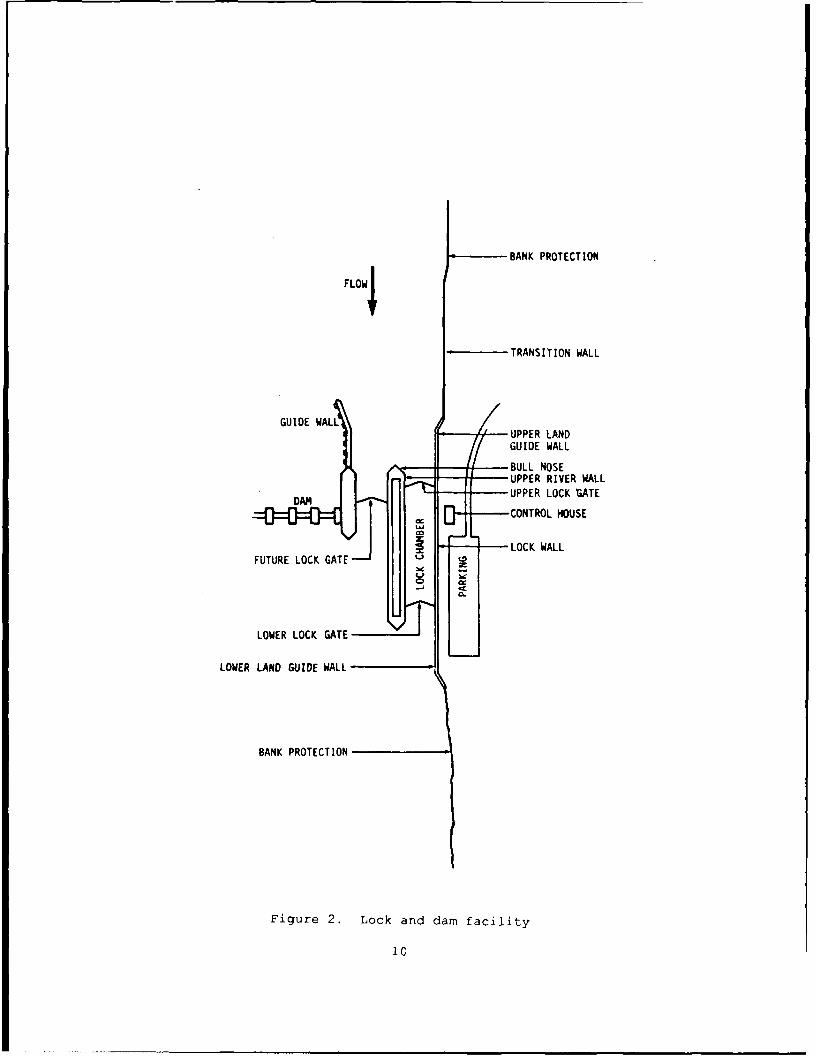
BANK PROTECTION
FLOW4
TRANSITION WALL
GUIDE WALL UPPER LANDGUIDE WALL
BULL NOSE'UPPER RIVER WALL
DAM UPPER LOCK rzATE
tCONTROL HOUSE
J LOCK WALLFUTURE LOCK GATE
LOWER LOCK GATE
LOWER LAND GUIDE WALL
BANK PROTECTION
Figure 2. Lock and dam facility
'C
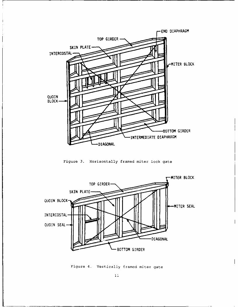
END DIAPHRAGMTOP GIRDER-
SKIN PLATE
INTERCOSTAL
rMITER BLOCK
BOTTOM GIRDER
INTERMEDIATE DIAPHRAGM
DIAGONAL
Figure 3. Horizontally framed miter lock gate
MITER BLOCKTOP GIRDER
SKIN PLATE---
QUOIN BLOCK-*--MTERSEAL
INTERCOSTAL-
QUOIN SEAL--a.0
DIAGONAL
BOTTOM GIRDER
Figure 4. Vertically framed miter gate
11

FLANGE-
END DIAPHRAGM
THRUST DIAPHRAGM
FLANGE
Figure 5. Tapered end and quoin post
convex surface of about the same radius. These two surfaces bear on each
other when the gate is in the mitered position. On horizontally framed gates,
the quoin block and wall quoin are continuous from the top of the gate to the
bottom (Figure 3). On vertically framed gates (Figure 4), load is transferred
into the lock wall at the top and bottom horizontal girder, and the quoin
block and wall quoin are present only at these locations.
22. The miter blocks are located at the miter end of the horizontal
girders. Miter blocks serve to transmit the axial load of the girders between
the two leaves in the mitered position. On horizontally framed gates, miter
blocks (like quoin blocks) are continuous along the entire height of the gate.
On vertically framed gates, miter blocks (like quoin blocks) are present only
at the top and bottom horizontal girder.
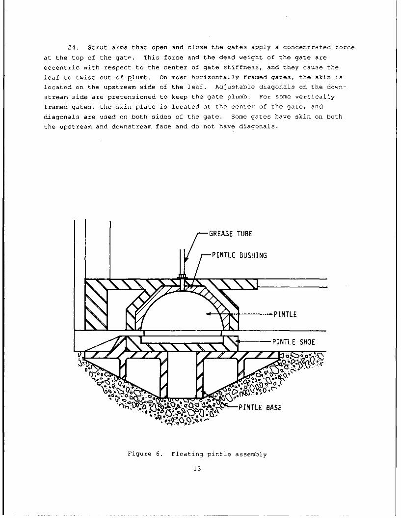
23. Pintle assemblies used for both horizontally and vertically framed
miter lock gates consist of two types: floating and fixed. The floating
pintle (Figure 6) fits into a cast steel shoe that is not fastened to the
pintle base, .allowing the lower corner of the gate leaf to move outward if
debris is lodged in the quoin. The fixed pintle fits into a cast steel shoe
that is bolted to the pintle base. Keyed pintles, which permit sliding in
only one direction, are also used.
12
24. Strut arms that open and close the gates apply a concentrated force
at the top of the gate. This force and the dead weight of the gate are
eccentric with respect to the center of gate stiffness, and they cause the
leaf to twist out of plumb. On most horizontally framed gates, the skin is
located on the upstream side of the leaf. Adjustable diagonals on the down-
stream side are pretensioned to keep the gate plumb. For some vertically
framed gates, the skin plate is located at the center of the gate, and
diagonals are used on both sides of the gate. Some gates have skin on both
the upstream and downstream face and do not have diagonals.
GREASE TUBE
--3PINTLE BUSHING
• - PINTLE
I: ~PITL -- S-HOE IT
PITL BASE
0~
Figure 6. Floating pintle assembly
13

25. Embedded anchorages distribute the top reaction of the leaf into
the concrete wall (Figure 7).
26. The parallel and perpendicular anchorage links are made up of
pinned ends connecting the gudgeon pin to the embedded anchorage. Most
anchorage links have an adjustable length, typically either a threaded section
or wedges (Figure 7). An alternative parallel anchorage is shown in Figure 8.
This assembly is made of two anchor links connected by a linkage pin.
27. Gudgeon pins are large-diameter pins of forged alloy steel (Figure
7). The gudgeon pin fits into a bronze bushing (Figure 7). This assembly
serves as the only connection between the top of the gate and anchorage links.
28. Rubber seals are used on the bottom of horizontally framed gates.
Various types of seals are used, but the most common is the round rubber seal,
which is used in regions having a wide range of temperature, and the "J" seal.
Seals are used at the quoin and miter on vertically framed gates.
14

0
o 0 WALL QUOIN AND ANCHORLENGTH ADJUSTER
QUOIN BLOCK
a. PLAN VIEW
ANCHORAGE ASSEMBLY LINKAGE BAR UGO I
b. SECTION VIEW
Figure 7. Upper anchorage assembly
15

oJ (
\GUDGEON PIN
LINKAGE PIN
~LINKAGE ARM
.0 0
\ADJUSTMENT WEDGE
"00
@D.o,.
Figure 8. Double linkage pin assembly (components)
16

PART II: FIELD INSPECTION
29. The ideas behind the inspection procedure are simplicity and adapt-
ability. As meetings and field tests with Corps personnel progressed, it
became increasingly clear that any miter lock gate inspection program must be
simple to learn and adaptable to different heights of gates. Current
inspection procedures varied significantly among the various districts. For
high-lift locks, inspection procedures tended to be more extensive, with less
tolerance for misalignments and imperfections. For low-lift locks, inspection
procedures were not as rigid, and more deviations from the perfect case could
be tolerated.
30. With these restrictions, the field inspection had to be based on
easily obtainable data, which were taken to be those obtainable from on top of
the gate cr the lock wall or from a boat in the lock chamber. The normal
inspection would involve no underwater diving. No ultrasonic or other
sophisticated devices could be used. All data would be measured by subjective
observation (poor, average, good, excellent, etc.), a tape measure, a level, aruler, dial gages, a camera, and the like. As a goal, the data would be
recorded by technicians having no specific engineering training or experience
in the design or construction of miter lock gate structures. Data would be
collected from the gate with the lock in an operating mode, that is, not
unwatered. Minimal disturbance to lock traffic was a requirement.
31. Of course, if the inspection can be conducted in conjunction with a
dewatering or divers, the additional information would be useful. Inspectionby diving teams would help to validate the visual inspection suggested herein.
At meetings with Corps personnel, some suggested that diving be a part of the
inspection while many stated that diving inspections were not warranted. For
the time being, the authors have decided to go with the simplest approach.
32. The inspection process generally follows this pattern:
a. Historical information, such as drawings and previous inspec-tions, is reviewed and recorded before a site visit.
b. A site inspection is conducted and specific visual data arerecorded.
c. The inspection data are entered into a personal computer program(MITER).
33. The results of the inspection (e.g., the condition index) are
intended to be indicative only of the existing condition and must be viewed as
such. For some cases, it may be necessary to return and conduct a moredetailed inspection that might include diving or surveying. This will clearly
be the case if a dangerous condition is indicated by the initial inspection.
It is beyond the scope of this report to describe a detailed inspection and
evaluation.
17

Overview of the Inspection Form
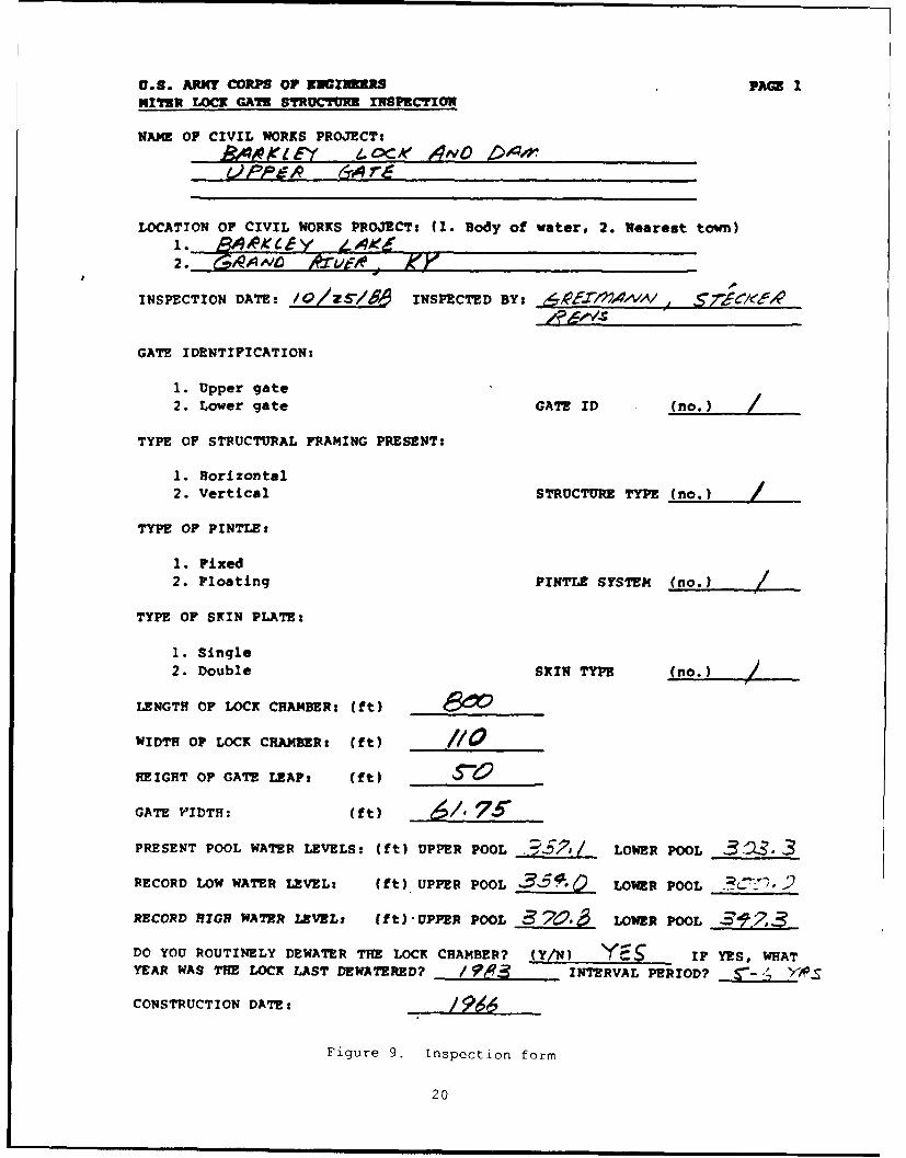
34. The inspection form (Figure 9) has been designed to provide flexi-
bility in documenting a variety of field conditions within one standard form.
Though there are nine pages in the inspection form, data for the last four
pages can be entered prior to the initial inspection and do not change for
subsequent inspections. These pages need be entered only if the structural
condition index is required. The following section illustrates the use of the
inspection form; the following paragraphs briefly outline the inspection form.
Historical information
35. Historical information related to the miter lock gate structure is
recorded on pages 1 and 2 of the inspection form. Information includes pro-
ject reference data to identify and locate the specific structure. Further
data categorize the structure into a particular type and function. The
information is also used to sort through the expert rules in the evaluation
model. The recent history of maintenance, modifications, inspections, and the
like is recorded. Finally, a section to record present-day physical condi-
tions of nonessential miter lock gate accessories is also provided.
Field measurements
36. Pages 3 to 5 of the inspection form are for recording measurements
made in the field. Several measurements are requested, such as anchorage
movements, bearing block gaps and offsets, downstream movements, elevations,
dents, cracks, noises, leaks, and corrosion levels. All of these field
measurements are used with the expert rules described in Chapter 4 to deter-
mine the functional condition index for the gates.
37. Some measurements on these pages are made at four different leaf
positions:
a. Recessed: For this case, the leaf is completely open.
b. Near miter: For this position the gates are brought to and heldat a location with about 4 ft between the miter blocks.
c. Miter, 1-ft head: The gates are brought to full miter and thevalves are opened to place a nominal 1 ft of head on the gates.The small head closes some gaps and stabilizes the gate duringthe measurement process.
d. Miter, full head: Full hydraulic head is applied to the gate.
Structural components
38. Information relative to the structural components of specific,
horizontally framed miter lock gate structures is recorded on pages 6 through
9 of the inspection form. If a vertically framed gate is selected on page 1
of the inspection form, pages 6 through 9 of the inspection form need not be
completed. The information compiled on these pages provides the basis for an
elementary review of the structural adequacy of the leaf. Most of the struc-
tural data will be recorded on the form prior to the site visit; it can be
18

verified during field inspection. The information may be taken from original
design drawings, as-built construction drawings, or drawings of field modifi-
cations to the structure.
General notes
39. The layout of the inspection form in Figure 9 has been designed to
facilitate both the data collection process and also the computer input and
evaluation model. After the initial inspection and computer modeling of a
structure, the data on pages 6 through 9 of the inspection form will become
relatively permanent and will require only nominal editing of computer data
files to keep them current. Pages 1 through 5 of the inspection form,
however, are data pages that in general must be filled out in the field during
the inspection because the information is subject to change. The following
pages of this manual duplicate the inspection form, with entries from a test
inspection. The side-by-side arrangement of the following pages displays
specific explanations adjacent to the entry on the inspection form. Pages 3
through 9 of the inspection form also have notes on how to measure and record
critical data.
19
U.S. ARMY CORPS OF ENIu3RS PAM INITER LOCK GATE STRUCTUR INSPECTION
NAME OF CIVIL WORKS PROJECTS
A J KI 1N .. A" 4NO 1,1.lr
LOCATION OF CIVIL WORKS PROJECT: (I. Body of water, 2. Nearest town)
2. j1~A,
INSPECTION DATE: /O/zsYM INSPECTED BY: ,, ,,v,,A; ,
GATE IDENTIFICATION:
1. Upper gate2. Lower gate GATE ID (no.)
TYPE OF STRUCTURAL FRAMING PRESENT:
1. Horizontal2. Vertical STRUCTURE TYPE (no.)
TYPE OF PINTLE:
1. Fixed2. Floating PINTLE SYSTEM (no.)
TYPE OF SKIN PLATE:
1. Single
2. Double SKIN TYPE (no.)
LENGTH OF LOCK CHAMBER: (ft)
WIDTH OF LOCK CHAMBER: (ft) /
HEIGHT O? GATE LEAF: (ft) _ -- _
GATE VIDTH: (ft) Z5/0 7 5
PRESENT POOL WATER LEVELS: (ft) UPPER POOL . !, LOWER POOL 3 3. 3
RECORD LOW WATER LEVEL% (ft) UPPER POOL _ ___ LOWER POOL _ -_.__
RECORD 14ZGR WA7ER LEVELS (f t) UPPER POOL 3 C.~ LOWER POOL 3 -3
DO YOU ROUTINELY DEWATER THE LOCK CHAMBER? (Y/N) . IF YEs, WHATYEAR WAS THE LOCK LAST DEWATERED? / INTERVAL PERIOD? -
CONSTRUCTION DATE: /2t
Figure 9. Inspection form
20

Page 1 Comments: Historical or Recordkeeping Data.
Completed prior to the site inspection and verified or changed during the siteinspection.
Data blanks on page 1 prefaced by (No.) __ must be recorded as numbers.
Enter in NAME the Corps of Engineer Project Title.
Indicate the BODY OF WATER. This may be a river, canal or improved channel,lake, or coastline.
Indicate GATE IDENTIFICATION, TYPE OF FRAMING, TYPE OF PINTLE, and TYPE OFSKIN PLATE by entering the appropriate number in the blank following eachname. Refer to the section called "Miter Lock Gate Component Identification"for descriptions and illustrative figures if additional information isrequired.
Enter nominal LENGTH and WIDTH of lock chamber (e.g., 600 ft. or 1200 ft.)Enter nominal WIDTH and HEIGHT of gate leaves.
Water level gage readings referenced to mean sea level. PRESENT and RECORDLOW and HIGH WATER LEVELS are important for reference.
Lock chamber dewatering periods and construction information may be importantfor reference.
21

U.S. ARMY CORPS OF RNGINRS PAGE 2
MITER LOCK GATE STRUCTURE IUSPECTION
ARE ORIGINAL GATE LEAVES CURRENTLY IN PLACE? (Y/N)
IF NOT, IDENTIFY CURRENT GATE LEAF HISTORY:
ARE DRAWINGS AVAILABLE FOR GATE LEAVES IN PLACE? (Y/N) >6
ARE THE DRAWINGS INCLUDED WITH THIS FILE? (Y/N) /V
PAST 10 YEAR HISTORY
MAJOR MAINTENANCE, REPAIRS, OR OTHER MODIFICATIONS
DATE DESCRIPTION
(1):
(2):
(3):
(4):
PREVIOUS INSPECTIONS OR STRUCTURAL REVIEWS (attach copies if available)
DATE DESCRIPTION
(1):
(2):
(3):
(4):
TYPE OF FENDER PROTECTION AND CONDITION OF FENDERS:
TYPE OF WALKWAY ON GATE LEAF AND CONDITION OF WALKWAY:
OTHER COMMENTS:
Figure 9. Inepection form (cont.)

Page 2 Comments: Historical or General Data.
Completed prior to the site inspection and verified or changed during the siteinspection.
Gate leaves are sometimes replaced or removed during rehabilitation. It isimportant for later reference to record the history of the in-place gate.
The next two sections are expanding records and can record up to 10 lines ofdata. Dates and descriptions are entered on one line as one record. Eachrecord is limited to 70 characters.Record major MAINTENANCE, REPAIRS, OR OTHER MODIFICATIONS performed on thestructure within the last 10 years.
Record PRESENT DAY type (steel or timber) and condition of fender protection.
Record PRESENT DAY type and condition of walkway and hand rails on gate leaf.The items noted in this section are for information only and do not affect thecondition index rating of the structure. They are recorded in the inspectionfile for reference and so that changes can be observed.
23

U.S. ARMY CORPS OF ENGINEERS PAGE 3MITER LOCK GATE STRUCTURE IrNSPECTION
FACING DOWNSTREAM AT UPPER GATE, IDENTIFY LEAF AS LAND OR RIVER SIDELEFT GATE LEAF - 4"A>/
RIGHT GATE LEAF -
OPENING AND CLOSING OF GATE LEAVESLEFT GATE % CLOSED RIGHT GATE I CLOSED
DO THE DIAGONALS FLAP? (Y/N) (Y/N) YDOES THE GATE JUMP? .(YIN) . (Y/N) /IS THERE GATE NOISE? (Y/N) o/ __Y/NI _,__," _ _
DOES THE GATE VIBRATE? (Y/N) IV (Y/N) ____
ELEVATIONS OF GATE LEAPNEAR MITER MITER
LEFT LEAF RECESSED MITER 1'HEAD FULL HEAD
QUOIN 9147 _____ 9,7MITER q,____ -',S,
RIGHT LEAF
QUOIN ,6 4,T-- 17 .Y7
MITER Q I _ '.5-1 -fsT
ANCHORAGE SYSTEM MEASUREKIr:T (Dim. 1, 2, 3)
IS THE CONCRETE CRACT7J OR SPALLED AT LOCATION I?
LEFT GATE RIGHT GATEPARALLEL ARM: Y!N) (Y/N) ,
PERP. ARM: Y/N) , Y/N) "
LEFT GATE NEAR MITER MITERARM DIM.(in) RECESSED MITER IHEAD FULL HEAD
PARALLEL 1: ol lys 0,!!21 0,PARPLLEL 2t . . 4*49./2- .2-1 4-.? -PARALLEL 3: /a, . .i,
PER P. 2: - -Big _RZC
PERP. 3: '57 ______
RIGHT GATE NEAR MITER MITERARM DIM.(in) RECESSED MITER 1' HEAD FULL READ
PARALLEL 1: Q . Q,3' I,. C, 349PARALLEL 2 : 4 337c 4,,Ps 13 - /ZPARALLEL 3: /,6.z$ / 5. 6__, 3.
PERP. 1: .1.,K /0 , .- __.___
P,,R,. . _::! ."- 41.;70_. a, 5. 20_ :/j-PERP. 3: 0?/__ 1/~/
Fiqur, 9. Inspect I n fo rc (cont.)
'4

Page 3 Comments: Field data.
Completed at site inspection.
Record the orientation of the lock chamber relative to the land by facingdownstream and identifying the left and right gate as the land or river side.
OPENING AND CLOSING OF GATE LEAVES: Observation of the gate leaves duringoperation (opening and closing) is a good indicator of problems. If thediagonals make a flapping noise, or if the gate vibrates (chatters), indicatethe approximate positions at which the noise or vibration occurs. Similarly,record the occurrence and positions of any unusual noises or jumping movement.
ELEVATIONS OF GATE LEAVES: When the gate leaves are in the recessed position(1), measure the miter and quoin elevations of each leaf. A specific pointshould be identified and marked at each of the four locations, usually on thewalkway, near the quoin and miter. Measurement should be made with a rod andlevel. Repeat this process for three additional positions: (2) near miter(approximately 4 ft from miter), (3) miter with 1 ft of head in chamber, and(4) mitered with full head. Measurement should be recorded or interpolated tonearest 0.005 ft, e.g., 1.115.
ANCHORAGE SYSTEM MEASUREMENT: The parallel and perpendicular anchorage armsare parallel and perpendicular, respectively, to the lock chamber. Indicatethe presence of excessive concrete cracking at location 1 where the anchorageenters the concrete (Figure 10) . Excessive concrete spalling may indicatethat a displacement occurred at this location at some point in time and may ormay not show up at a current measurement. Hairline cracks, probably caused bythermal expansion or contraction of the concrete, should be ignored in thisanalysis.
Measurements must be made on both parallel and perpendicular anchorage arms atfour leaf positic-s: (1) recessed, (2) near miter (approximately 4 ft frommiter), (3) mitered with 1 ft of head, (4) and mitered full head. Dimension 1can be measured with a dial gage attached to a magnet. The magnet is placedon the steel of the anchorage arm with the dial gage plunger pushing on theconcrete wall. Displacements should be recorded to 0.001 in.
Dimension 2 can be measured with a ruler or tape measure between two scribemarks. One scribe mark should be on each side of the length adjustment device(turnbuckle, wedges, etc.). Connection pins should be between the twoscribes. As noted in Chapter 1, some anchorages have an additional pin.Measurement 2 should be made across this pin also. Measurement 2 must includemovemr't in all linkage pieces except the concrete/steel interface (Dimension1) and at the gudgeon pin (Dimension 3). In some cases, the measurementcannot be made between two scribe lines because of geometrical interferences.In these cases, the authors have contrived assemblages of C clamps and strapsof steel to obtain the change in length between the two points.
Dimension 3 is also measured with a ruler or a tape measure. In the simplestcase, the measurement is between a scribe point on the gudgeon pin arm and apoint at the center of the gudgeon pin. The measurement is intended to detectwear in the pin and/or bushing. In most cases, the simple approach is notavailable because of geometric interferences. Often it is necessary to pto-ject the point on the gudgeon pin area upward, above interferences with theleaf or other obstructions. C clamps and strap steel have been used for this.Often the center of the gudgeon pin is not accessible. Steel plates may haveto be removed. A grease pipe may be at the pin center. A bolt or pipe may bescrewed into the center, if threads are present, to extend this measurementpoint upward. Ingenuity is often required for this important measurement.
25

U.S. ARMY CORPS OF ENGIEERS PAGE 4
MITER LOCK GATE STRUCTUR I SPCTION
MITER AND QUOIN ZEARING IMASUIEK;NT-
OFFSET OF MITER BLOCKS WITH GA':cS AT 'iTHP (1'FEAD), (DIM. 4, 5)
LOCATION MEASUREMENT fin." WALKWAY DISTANCE (f t) GATE DOWNSTREAM
TOP: 2 __5 __ (LIE) LDSWL: _ _ 0 (L/R) ,
(DSWL - DOWS ,T.2-- '; A , .Th 1H EAD ON GATES-
GAP BETWEEN BEAPING BLO.' 1 r'?'tS AT MITrP C1'HEAD), (DIM. 6, 7)
LOCATION iP-, QYNT (in.), ':'ALKWAY DISTANCE (ft)
LEFT QUOIN @ TOP4 6,0LEFT QUOIN @D'b -i iZ IRIGHT QUOIN 0~_______
RIGHT QUOIN e1S.,
MITER -T"P: ________
MITER @ VSWL 1"..2 r2.. .. _-_
LONGITUDINAL PC'I'T ,'" ... 8,
LOCATION '', r -i')D WALKWAY DISTANCE (ft)TO P :3
IJSWL: _ _ _ _ _ _ _ _ _
LCK CHAMER IL' ORI
DOES ThE GATE VIBRAIU11T.' ) "
DOES A LEAK FOLLCA' Th? PISP' CP 7MPTYING) LEFT QUOIN: (Y/N)
WATER LEVEL AND -h_., 'LO'.. , : 'W7 WA7?R MITER ( _
CONTINUES TO. RIGHT QOOIN: (Y/N) /V
DOES TEP GAP BE'7" '-. Al" r- (Y/N) \f'
IF YE5, SELE-T '•,: ; HB MOST ACCURATE DESCRIPTION OF
THE CHANGE. (<..
1. TOP CAP NI.. .';:W.R FULL 7FAD.2. 'TOP GAP OFE. 2 .: .... "X,1. 21L. iULL HEAD.
3. TOP GAP OPENS i'ND P1I.ML N7 ,..2.S'.
4. TOP OF M IS ,.... . (:Ac' OPENS PETWEN WATER LINE AND TOP.5. TOP OF MITER IS A)C,. 7)" 1 JA P:/T'F.EN WATER LINE AND TOP CLOSES.
ESTIMATF THF MJAXIH"'' k' T cr' ( N. I. 3ESTIMATE THE LOCATION (- " ,1?,DM e% .AP FROM THE WALKWAY (FT.) /7. C-'

Page 4 Comments: Field data.
MITER BLOCK OFFSET: The offset of miter blocks at the top of the gate,Dimension 4, and at the downstream water level (DSWL), Dimension 5, along withthe vertical distance from the walkway to each measurement can be made with aruler and tape. See Figure 11 for illustration of miter offsets. The gateleaves should be in the mitered position with 1 foot of head in the chamber tostabilize the gates. In addition, record the relative orientation of theleaves by indicating which gate is farther downstream, left (L) or right (R),at each measurement.
BEARING BLOCK GAPS: Bearing blocks include the land quoin (LQ), river quoin(RQ) (Dimension 6, Figure 11), and the miter (Dimension 7, Figure 12). Thegap measurement between bearing blocks at the top of the gate and at thedownstream water level (DSWL) along with the vertical distance from thewalkway to each measurement can be made with a feeler gauge or ruler and atape measure. The gate leaves should be in the mitered position with one ftof head in the chamber to stabilize the gates.
LONGITUDINAL POSITION OF MITER POINT: The longitudinal position of the miterpoint at the top of the gate and at the downstream water level (DSWL) alongwith the vertical distance from the walkway to each measurement are recorded.To make this measurement, the authors have attached rulers near the miterblock on a leaf at both the top and the DSWL. The rulers are oriented suchthat the readings increase downstream. A transit is located on the lock wallsuch that both rulers can be read over the edge of the wall. The verticalcross hair establishes a vertical plane from which the readings are made.These measurements should be made with the gate leaves closed with 1 ft ofhead in the chamber and at full head.
LOCK CHAMBER FILLING OR EMPTYING: As the lock chamber is filling, waterpassing underneath the gate may cause the seals to flutter (vibrate). Placingyour ear near the walkway railing will amplify this noise as the gatevibrates.
Changing characteristics of the gaps may help an experienced engineer identifythe cause and/or magnitude of bearing block problems. A leak between theblocks indicates a gap. If the leak stops as the water rises or falls, thegap has closed. If a LEAK FOLLOWS THE RISING (OR EMPTYING) WATER LEVEL ANDTHEN CLOSES AGAIN, record this occurrence. Chapter 4 discusses theimplications of changing gaps.
For the visible portion of the gap above the water, answer whether THE GAPBETWEEN MITER BLOCKS CHANGES? If the answer is YES, provide the most accuratedescription of the gap opening and closing changes. Also, estimate theMAXIMUM WIDTH OF GAP and its LOCATION.
27

U.S. ARMY CORPS OF ENGINEERS PA 5MITER LOCK GATE STRUCTURE INSPECTION
OBSERVATIONS FROM BOAT
CORROSION AT SPLASH ZONE (LEVEL 0,1,2,3,4, or 5)
LEFT GATE (LG) RIGHT GATE (RG)UP STREAM DOWN STREAM UP STREAM DOWN STREAM
SKIN: I / __
GIRDER: mi:: 4/
INTERCOSTAL: __z
DENTS -- SKIN PLATE (S), GIRDERS (G), or INTERCOSTALS (I)GATE COMPONENT LOCATION, DISTANCE FROM: SIZE (ft)
L or R S, G, or I WALKWAY (ft) QUOIN (ft) HEIGHT WIDTH(1): 0 &S(2):
(3):
(4):(5):
CRACKS -- SKIN PLATE (S), GIRDERS (G), or INTERCOSTALS I)GATE COMPONENT LOCATION, DISTANCE FROM: SIZE (ft)
L or R S, G, or I WALKWAY (ft) QUOIN (ft) LENGTH(1): _ _ _ _ _ _ _ _ _ _ _ _ _ _ _ _ _ _ _ _ _ _ _ _ _ _
(2):
(3):
(4):(5): _ _ _ _ _ _ _ _ _ _ _ _ _ _ _ _ _ _ _ _ _ _ _ _
BEARING BLOCK LEAKS @ LEFT (L), MITER (M), or RIGHT (R)TYPE -- L M,R DISTANCE FROM WALKWAY (ft) LENGTH (ft)(1): , _), _ . -(2): * j _ _ , _ _ _ __ _ _ _(3):
(4):
(5):
SKIN LEAKS @ LEFT GATE (L), RIGHT GATE (R)GATE TYPE SHORTEST DISTANCE FROML or R (W)OR OR CV)ERT WALKWAY (ft) QUOIN (ft) LENGTH (ft)
(1): _
(2):
(3):,4):
(5):
BOILS @ LEFT GATE L), RIGHT GATE (R), MITER (M)TYPE (L,R, or M) DISTANCE FROM QUOIN (ft)
(2): -
(3):
(4):(5)"
9. [ rf- ¢ f, (ccnt.)
28

Page 5 Comments: Field Data.
CORROSION AT SPLASH ZONE: The corrosion of the skin plate, girders, andintercostals is rated in a visual subjective manner. Refer to Chapter 4 formore details on the rating scheme. Selection of the corrosion level observedat the splash zone (air/water interface) is made by comparing the observedcondition to the standards in Table 4 and/or visually comparing it to thephotographs in Figures 25 to 28. There are five levels of deterioration.Level 0 is new or nearly equal to new. Upstream and downstream levels arerecorded.
DENTS: The location and dimension of skin plate, intercostal, and girderdents are determined by a ruler or tape measure. The coordinates of the dentare taken as the distance from the walkway and quoin corresponding to thespecific gate leaf.
CRACKS: The location and length of skin plate, intercostal, and girder cracksis made with a ruler or tape measure. The coordinates of the crack are takenas the distance from the walkway and quoin on the specific gate leaf to thenearest point of the crack.
BEARING BLOCK LEAKS: The location and length of the left quoin (L), rightquoin (R), or miter (M), bearing block leaks are measured with a tape measure.The location of the leak is determined as the distance from the walkway to thetop of the leak. A leak of length zero indicates a point or local leak.
SKIN LEAKS: The location and dimension of skin plate leaks are measured by atape measure. Two types of skin plate leaks usually exist: horizontal (H)indicates a horizontal leak and vertical (V) indicates a vertical leak. Thecoordinates of the leak are taken as the distance from the walkway and quointo the top of the leak. The corresponding gate leaf, right (R) or left (L),is also recorded.
BOILS: The existence of boils from below the water surface on the right gate(R), left gate (L), or at the miter (M) will be noted by location (distancefrom the quoin).
29

U.S. ARM- CORPS OF ENGINEERS PAGE 6
MITER LOCK GATE STRUCTURE SAFETY INSPECTION
Calculation date: _ Calculated by: Xw6"MS
REQUIRED OVERALL VERTICAL GEOMETRY -- (FIG. 13.)
Positive elevation of sill above any datum, ELSILL (ft):Sill to bottom of skin plate, GBOT (ft): 02=f:Sill to overflow elevation at top of gate, GTOP (ft): 44.7s
REQUIRED OVERALL LEAF GEOMETRY - (FIG. 13.)
Leaf between contact points, GLENG (ft):Gate leaf slope, GSLOPE:Working line to downstream edge of girder webs, GWORKL (ft): e2l±, "="
Quoin contact point to gudgeon pin, GQUOIN (ft): /-!7Working line to gudgeon pin (positive when contact point is downstream from
gudgeon pin), GPINl (ft): 1,2S-
COMMON GIRDER GEOMETRY DIMENSIONS -- (FIG. 13.)
Girder web depth, GWEBD (in): ___,O_
Quoin contact point to center of nearest end diaphragm along working line,
DQPED (in): 8Center of end diaphragm at miter end of gate to miter contact point along
working line, DEDMP (in): 48.Bottom girder downstream flange extension below web centerline,
BGDFD (in): H
GIRDER ELEVATIONS -- (FIG. 13.)
Number of girders in the gate leaf, NGIRDS: //Girder Number, NGTRD Vertical distance above sill, VD (ft)
~,-I s-.
ri;fpection foirr, (cont.)
30

Page 6 Comments: Structural Components Data
Complete prior to the site inspection and verify or change data during thesite inspection. Data must be recorded in the indicated units.
REQUIRED OVERALL VERTICAL GEOMETRY: Provide the overall vertical leafdimensions based on the available design drawings. ELSILL is the positiveelevation of the sill above any datum, usually referenced to mean sea level.GBOT is the clear space between the sill and the bottom of the gate, and GTOPis the distance from the sill to the overflow elevation (top of skin plate).See Figure 13 for illustration.
REQUIRED OVERALL LEAF DIMENSIONS: Provide the overall leaf dimensions basedon the available design drawings. GLENG is the length of leaf between quoinand miter contact points. GWORKL is the distance from the working line to thedownstream edge of the girder web. GQUOIN is the distance along the gate leafworking line from the quoin contact point to the gudgeon pin, and GPINI is thedistance from the working line to the gudgeon pin. See Figure 13 forillustration.
GIRDER COMMON DIMENSIONS: Provide the overall girder dimensions based on theavailable design drawings. GWEBD is the depth of the web plate or the cleardistance between girder flanges. DQPED is the distance along the gate leafworking line from the quoin contact point to the end diaphragm. DEDMP is thedistance along the gate leaf working line from the miter contact point to theend diaphragm. DQPED and DEDMP are usually equal. BGDFD is the bottom-girderdownstream flange, downward extension below the web centerline. See Figure 13for illustration.
GIRDER WEB ELEVATIONS: Indicate the number of girders, NGIRDS, and providethe girder number, NGIRD, and the vertical distance, VD, above the sill,ELSILL, for each girder. See Figure 13 for illustration.
NOTE: The information furnished on this page serves as input to the CMINVmodule (see Chapter 3). The notation is identical to the CMINV documentationreferred to in Chapter 3.
31

U.S. ARMY CORPS OF ENGINEERS PAGE 7MITER LOCK GATE STRUCTURE SAFETY INSPECTION
GIRDER DIAPHRAGM SPACING - (FIG. 13.)
Top girder Bottom girder Spaces between Itrcstl spacesof similar pnl of similar pnl end diaphragms btwn adj dphrgms
NPANLI NPANLN NDS NIS
DEAD AND LIVE LOADS:
Additional dead load, including ice, mud walkway, gusset plates, etc,ADEAD (lbs.): 4Quoin contact point to centroid of ADEAD along working line,XDEAD (ft): ./-ODownstream edge of girder web to controid of ADEAD, ZDEAD (in.):Bouyancy force acting on dry weight of gate, ABUOY (lbs.): 9 p2tzQuoin contact point to centroid of ABUOY along working line,XBOUY (ft.): --!/Downstream edge of girder web to centroid of ABOUY, ZBOUY (in.): /Concentrated live load, including walkway and bridgeway,ALIVE (lb.): C2REQUIRED WATER ELEVATIONS -- (FEET ABOVE ELILL) (FIG. 14.)
Elevation of upper pool, ELUP (ft): ____
Elevation of lower pool, ELLP (ft): .
Full submerge elevation, ELFS (ft):
Operating water elevation, ELOW (ft): .3-S.L2
STEEL TEILD STRENGTH (1SI):
Miscellaneous Steel yield strength -36.__0
Webs Flanges Skin Stiffeners Intercostals Quoin Diaphragms
Figure 9. Inspection form (cont.)
32
Page 7 Comments: Structural Components Data
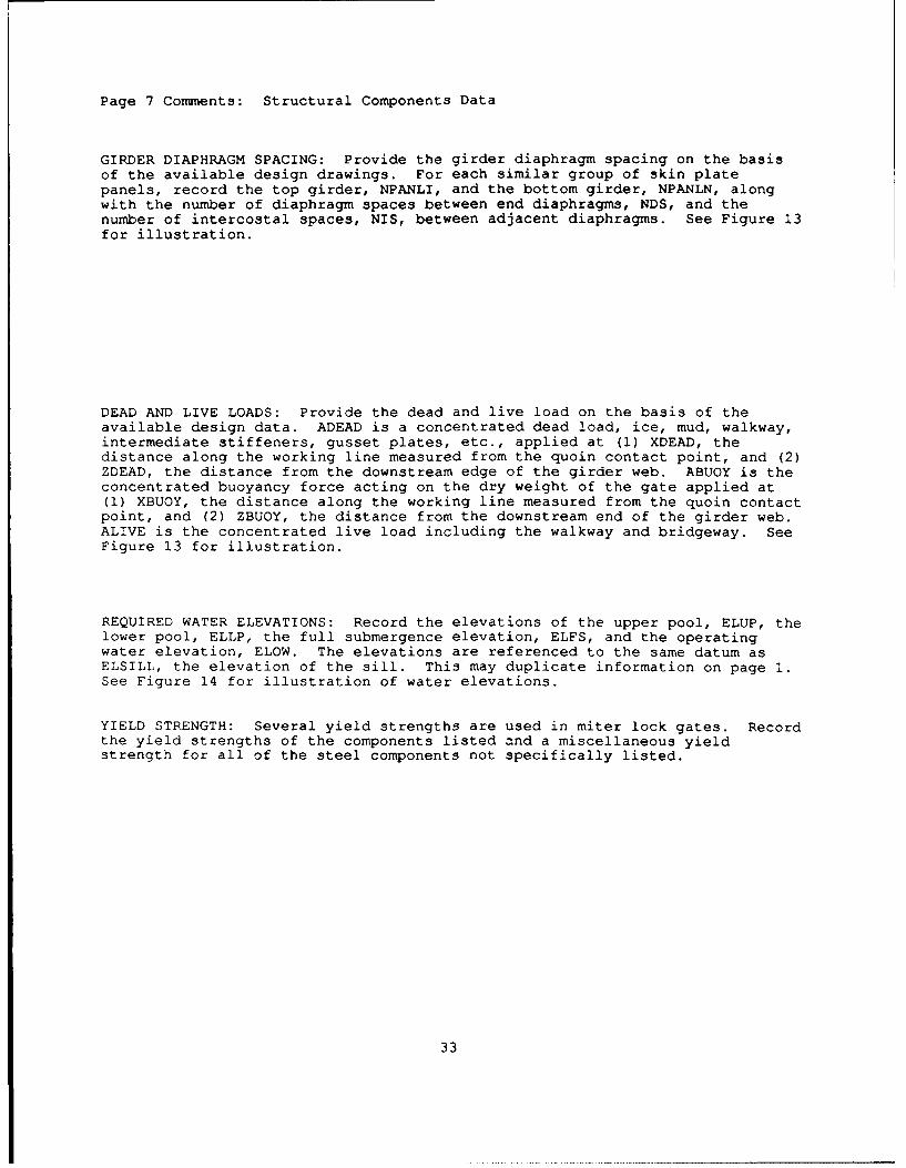
GIRDER DIAPHRAGM SPACING: Provide the girder diaphragm spacing on the basisof the available design drawings. For each similar group of skin platepanels, record the top girder, NPANLI, and the bottom girder, NPANLN, alongwith the number of diaphragm spaces between end diaphragms, NDS, and thenumber of intercostal spaces, NIS, between adjacent diaphragms. See Figure 13for illustration.
DEAD AND LIVE LOADS: Provide the dead and live load on the basis of theavailable design data. ADEAD is a concentrated dead load, ice, mud, walkway,intermediate stiffeners, gusset plates, etc., applied at (1) XDEAD, thedistance along the working line measured from the quoin contact point, and (2)ZDEAD, the distance from the downstream edge of the girder web. ABUOY is theconcentrated buoyancy force acting on the dry weight of the gate applied at(1) XBUOY, the distance along the working line measured from the quoin contactpoint, and (2) ZBUOY, the distance from the downstream end of the girder web.ALIVE is the concentrated live load including the walkway and bridgeway. SeeFigure 13 for illustration.
REQUIRED WATER ELEVATIONS: Record the elevations of the upper pool, ELUP, thelower pool, ELLP, the full submergence elevation, ELFS, and the operatingwater elevation, ELOW. The elevations are referenced to the same datum asELSILL, the elevation of the sill. This may duplicate information on page 1.See Figure 14 for illustration of water elevations.
YIELD STRENGTH: Several yield strengths are used in miter lock gates. Recordthe yield strengths of the components listed and a miscellaneous yieldstrength for all of the steel components not specifically listed.
33

U.S. ARMY CORPS OF ENGINEERS PAGE 8MITER LOCK GATE STRUCTURE SAFETY INSPECTION
GIRDER MS THXCTIMSSES (MN.) (FIG. 15.)Groups of similar girders Web end zone Web center zone
Top girder Bottom girder thickness thicknessNGIRDI NGIRDN GWET GWCT
_ / ///,0 e2
GIRDER FLANGES, UPSTREAm (IN.) -- (FIG. 15.)Groups of similar girders Upstream flange widthsTop Number Bottom Number
NGIRDI NGIRDN GUFEW GUP34W GUF4CW
C2Q 62 19 .ZS2zzzc~/ .- L /..2__J /.2.. /. ' / '.. ,€;;j;Z el/;>) !. ,.
_- z 2Q o /- / C17
Ups' ream flange thickness Upstream flange cover plateDistance from quoin Width Thickness
GUFET GUFCT GUCPX GUCPW GUCPT// ____ _____
_// _____7 / r_ 0
GIRDER FLANGES, DOWNSTREAM (IN.) -- (FIG. 15.)Groups of similar girders Downstream flange widthsTop Number Bottom Number
NGIRDI NGIRDN GDFEW GDFCW
_ /zz/!zzz
Downstream flancje thickness Downstream flange cover plateDistance from quoin Width Thickness
GDFET GDFCT GDCPX GDCPW GDCPT
Figure 9. Inspection form (cont.)
34

Page 8 Comments: Structural Components Data.
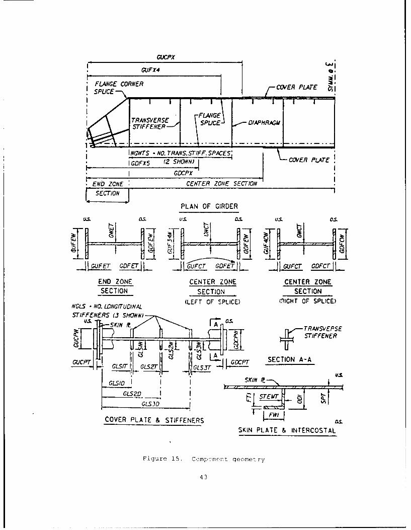
GIRDER WEB THICKNESSES: Provide the girder web thicknesses on the basis ofthe available design drawings. For each similar group of girder webthicknesses, record the top girder, NGIRDI, and the bottom girder, NGIRDN. Inaddition, the end zone web thickness, GWET, and the center zone web thickness,GWCT, must be recorded. See Figure 15 for illustration of girder webthicknesses.
GIRDER FLANGES, UPSTREAM: Provide the upstream flange widths and thicknesseson the basis of the available drawings. For each similar group of upstreamgirder flanges, record the top girder, NGIRDI, and the bottom girder, NGIRDN,along with the end zone width, GUFEW, and thickness, GUFET, from the girderend to the corner splice. Also record the flange width from the corner splicepoint to the flange splice point, GUF34W, and the flange width from the flangesplice point to the girder centerline, GUF4CW. The flange thickness, GUFCT,is usually the same in these two regions and must be recorded. In addition,the upstream flange, cover-plate distance from the quoin, GUCPX, width, GUCPW,and thickness, GUCPT, must be recorded. A zero in the last three entriesindicates that no cover plate is present. See Figure 15 for illustration.
GIRDER FLANGES, DOWNSTREAM: Provide the upstream and downstream flange widthsand thicknesses based on the available drawings. For each similar group ofupstream girder flanges, record the top girder, NPANLI, and bottom girder,NGIRDN, along with the end zone width, GDFEW, and thickness, GDFET, from thegirder end to the splice point. Also record the width, GDFCW, and thethickness, GDFCT, from the splice point to the downstream cover platelocation, GDCPX, width, GDCPW, and thickness, GDCPT, must be recorded. A zeroin the latter three of these entries indicates no cover plate is present. SeeFigure 15 for illustration.
35

U.S. ARMY CORPS OF ENGINEERS PACE 9MITER LOCK GATE STRUCTURE SAFETY INSPECTION
GIRDER FLAMM COORDINATES (FT) -- (FIG. 15.)Groups of similar girders Cover plate distance from quoinTop no. Bottom no. Upstream VownstreamNGIRDI NGIRDN GUFX4 GDFX9
GIRDER IEB STIFFENERS (IN.) -- (FIG. 15.)Groups of similar girders No. trans. stffnr No. of long
Top no. Bottom no. spcs btwn intrmdt dphr stffnr pairsNGIRDI NGIRDN NGWrS NGLS
a 92 2-ZL.. /.. / // / /ZL)
Longitudinal stiffener geometryStiffener number 1 Stiffener number 2 Stiffener number 3
Width Thcknss Width Thcknss Width ThcknssGLSID GLSIW GLSIT GLS2D GLS2W GLS2T GLS3D GLS3W GLS3T
4/ -.A -- _s_ _ 0 ___ c).5
INTERCOSTAL AND SKIN PLATE GEOMTRY (IN.) -- (FIG. 15.)Groups of similar intercostalsTop girder no. Bottom firder no. Skin plate thickness
NPANLI NPAN SPT
Depth (perp to skin) Stem thcknss Flng width Flng thcknssODI STEMT FWI VTI
612 C)
Figure 9. Inspection form (cont.)
36

Page 9 Comments: Structural Components Data.
GIRDER FLANGE COORDINATES: Provide the girder flange splice coordinates onthe basis of available design drawings. For each similar group of girderflange splice coordinates, record the top girder, NGIRDI, and the bottomgirder, NGIRDN, along with the upstream flange splice coordinates, GUFX4, andthe downstream flange splice coordinates, GDFX5. The coordinate is measuredfrom the quoin contact point as illustrated in Figure 15.
GIRDER WEB STIFFENERS: Provide the girder web stiffener information on thebasis of the available design drawings. For each similar group of girder webstiffeners, record the top girder number, NGIRDI, and the bottom girdernumber, NGIRDN. Also, record the number of girder web transverse (vertical)stiffener spaces, NGWTS, between adjacent intermediate diaphragms, and thenumber of longitudinal stiffeners, NGLS, between girder flanges. In addition,indicate for each of the longitudinal web stiffeners (1) the distance from thedownstream web edge, GLSID, (2) the width, GLS1W, and (3) the thickness,GLSIT. A zero entry indicates no stiffener present, and a negative entry fora longitudinal web stiffener width indicates stiffeners on only one side ofthe web. See Figure 15 for illustration.
INTERCOSTAL AND SKIN PLATE GEOMETRY: Provide the intercostal and skin plategeometry on the basis of the available design drawings. For each similargroup of panels, record the top girder, NPANLI, and the bottom girder, NPANLN,and the corresponding skin plate thickness, SPT, within this region. Inaddition, record (1) the overall depth of the intercostal, ODI (including theflange thickness), (2) the thickness of the perpendicular leg touching theskin plate, STEMT, (3), the width of the angle parallel to the skin plate(flange), FWI, and (4) the flange thickness of the intercostal, FTI. SeeFigure 15 for illustration.
37

:"
Figure 10. Double linkage pin assembly (dimensions)
38

II4 TOP OF GATE
III
______"_ 7 DSWLiI
SILL
Figure 11. Miter block offset
39

1 MITER BLOCK GAP
7.~.
000
00 QUO BLOK STGAP M.o'~
Figure 12 as dwsrammvmn
)040

- ~~~ GSLOPEIIWRKN
WEB / LI5E. D5. FLANGE
SeE DETAIL
QOINf
cotEt 1. ZOEAD. ZBUOY
JIxsucOY ELFS
--* ~ ~ --E 8 --
0I-!k PANL N.
NID2PANEL NO. Uq
N~iRD3 (6 HOWN PAVELNO.5 ~
USTR Tu FoRcE ELSILL
Figure 13. Leaf geometry
41

HEAD2HEADI ~ .EF
S FLOW
- ~ ELUP
SELLP
THEA 0 THEA 0
Figure 14. Water elevations (computer input)
42
GUCPX
GUFX4
' FLANGE CORNER CU/ER PLATESPUICE I
F GE
TRA•SVERSE FLANGESTIFFENER
NGIWTS- NO. TRANS. STIFF. SPACES; PjE;_ I GDFX5 (2 SHOW)JCVRPA~
I GDCPX
, ENb ZCNE CENTER ZONE SECTION ISECTION
PLAN OF GIRDER
us. os. u_. S. U. O.
2 GFET- GDFET Gof L 2 K 2 UFTCFCT LEND ZONE CENTER ZONE CENTER ZONE
SECTION SECTION SECTION
NGLS -NO. LONGITUINAL (LEFT OF SPLICE) (RIGHT OF SPLICE)
STIFFENERS (3 SttOWN)
-SKIN TRANSVEPSE7 STIFFENER
I SECTION A-A
" ,,- GLST'Gsz"
G oIS SKIN
GLS2D IETGLS30 E
COVER PLATE & STIFFENERS as.
SKIN PLATE & INTERCOSTAL
Figure 15. Compcnent geometry
43

PART III: STRUCTURAL CONDITION INDEX
40. Structural safety often refers to potential loss of life or signi-
ficant property damage. If a structure is unsafe, it is in danger of
collapse. Structural safety has traditionally been measured by a factor of
safety. Hence, uncertainties in loading and structural strength (i.e.,
emergency conditions) are accounted for by selecting an appropriately high
factor of safety to ensure a sufficient margin between the applied loads and
the structural resistance. For example, the design criteria for miter lock
gates typically require a factor of safety of two.
41. In this project a structural condition index is defined as a
measure of the safety of the structure or risk of failure of the structure.
It is based directly upon the calculation of a factor of safety of the
structure. The factor of safety calculation is often perceived as a fairly
rational, objective process. However, many simplifying assumptions must be
made. In fact, the structural analysis of a miter lock gate involves many
subjective decisions. Fortunately, many of the assumptions have been stan-
dardized and published by the US Army Corps of Engineers. Therefore, the
factor of safety and hence the structural condition index are at least
reasonably repeatable (relative to the functional condition index in the
following chapter).
Structural Analysis
42. A basic part of the structural safety evaluation is a structural
analysis. As with all structural analyses, several assumptions must be made.
In this work, the basic assumption is that miter lock gates behave in the
manner for which they were designed. With this assumption, the US Army Corps
of Engineers design manuals, 1963 and 1984, are used for the structural
analysis. These sources are supplemented by a US Army Corps of Engineers
computer program, CMITER (US Army Corps of Engineers, 1987), that implements
these rules for the horizontally framed gate.
43. Horizontally framed gates generally provide a more rigid structure
than vertically framed gates. For shallow gate leaves up to a height-to-width
ratio of 1, the vertically framed gate requires less material and weighs less.
The horizontally framed gate is used on higher lift locks. Horizontally
framed gates are used most frequently, with the exception of the Mississippi
River system. Approximately 95 percent of miter lock gates in service and all
new construction are horizontally framed. Moreover, CMITER analyzes only
44

horizontally framed gates; thus, the structural analysis in this study is
concerned with horizontally framed gates only.
44. The structural analysis module of CMITER, called CMINV, interfaces
with the inspection forms to perform a structural analysis of several com-
ponents on the horizontally framed gate leaf. The completed inspection forms,
pages 6 to 9, which serve as the input to CMINV, are described in Part II.
Because the input and output of CMINV is long and detailed, the structural
analysis in this project has been limited to three significant components:
girders, intercostals, and skin plate.
45. A computer program (MTR) has been written by project personnel to
postprocess the CMINV output file by calculating the factors of safety of the
three selected components. The computer selects the worst case in terms of
the lowest Condition Index of the three components for each of five load
cases.
Loads
46. The loads normally applied to miter lock gates consist of water
pressure, operating loads (opening and closing), boat impact, and dead and
live loads. Water pressure is produced by pool differential on the sides of
the gate as the lock is filled or emptied. Operating loads are the result of
the strut arm force and water resistance to the moving leaf as it is opened
and closed. Boat impact load is the force produced by barge and vessel
collisions with the gate. Dead load includes ice, mud, and the like, and live
load includes loads acting on the bridgeway and walkway. Abnormal or
emergency loads include any of the normal loads in addition to earthquake
loads, increased water loads (dewatering for maintenance), and temporal
hydraulic loads (temporal head) below the full submergence elevation (a pulse
load or a wave) (Figure 16).
47. The load types described above are grouped into six load cases.
Load Case 1
48. Load Case 1 is a normal operating condition in which the gate
leaves are in the mitered position and subjected to both upper and lower pools
(Figure 16). The Corps permits the use of 10 ft of head for girders and 6 ft
of head for skin plate to act as equivalent impact loads. The equivalent boat
impact load represents a minimum load to which the girders and skin plate are
subjected (Figure 17). Hence, it only loads the girders and skin plate in the
upper part of the gate.
49. Since Load Case 1 is a normal operating condition the allowable
stresses specified in the design manual (US Army Corps of Engineers, 1963) are
applicable. The design factor of safety, FSd, is 2.0.
45

FULL SUBMERGENCEWATER ELEVATION
ELEVATION OF OPERATING7 ,WATER (BOTH SIDES)
UPPER POOL L P
"- 7 LOWER Pool
~SILL
Figure 16. Water elevations
,//4--EQUIVALENT BOATIMPACT HEAD
V UPPERPOOL
LOWERPOOL
APPLIED PRESSURES NET PRESSURE
Figure 17. Load case 1
46

Load Case 2
50. Load Case 2 consists of the gate leaves in the mitered position
with water pressure due to the full upper pool only. This is the dewatered
condition (Figure 16).
51. Load Case 2 is an abnormal condition so that a 33-percent increase
in the allowable stresses is permitted. The design factor of safety, FSd, is
1.5.
Load Case 3
52. Load Case 3 consists of dead load (ice and mud) and the water drag
when the gate is opening or closing (Figure 16). Load Case 3 does not include
static water head.
53. Load Case 3 is an unmitered operating condition which permits the
normal allowable stresses. The design factor of safety, FSd, is 2.0.
Load Case 4
54. Load Case 4 is an unmitered operating condition consisting of the
gate weight, live load on the walkway and bridgeway, dead load of ice and mud,
and the temporal head (Figure 16). CMINV defaults to 1.25 ft head to
represent the temporal load (pulse load or wave resulting from overfill or
overemptying).
55. Load Case 4 has no static head and allows a 33-percent increase in
the allowable stress. The design factor of safety, FSd, is 1.5.
Load Case 5
56. Load Case 5, unmitered obstruction, usually controls the design of
the strut and pintle. The structural analysis in this project has been
limited to three components: girders, skin plate, and intercostals. Load
Case 5 does not stress these components and has been omitted.
Load Case 6
57. Load Case 6 consists of Load Case 1 (without boat impact) plus the
earthquake condition, which is represented by a constant gate acceleration
(default equal 0.05 g in CMINV).
58. Load Case 6 is the mitered earthquake condition resulting in a 33
percent increase in the allowable stress. The design factor of safety, FSd,
is 1.5.
Component Condition Index for Each Load Case
59. The minimum factor of safety for each of the three components for
each load case is determined. It is related directly to the structural
condition index by using the condition index zones in Table 2. If the factor
of safety is equal to the design value, the condition index is 100. If the
factor of safety falls below 1.0, a Zone 3 (condition index less than 40) is
47

indicated. Figure 18 illustrates the two straight lines that are used to
relate the factor of safety and the structural condition index.
{40 x FS FS < 1
40 + 60 FS -1 FS > 1(1)
where FSd is the design factor of safety.
Gi~lers
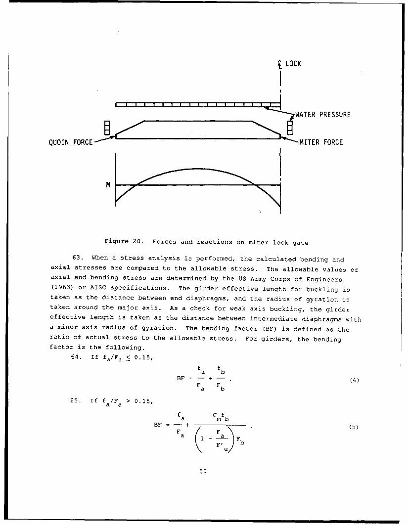
60. The main girders of horizontally framed gates in the full mitered
position of Figure 19 form a series of three hinged arches symmetrical about
the centerline of the lock chamber. The forces and reactions acting on one
gate leaf along with the corresponding moment diagram are shown schematically
in Figure 20. The determination of the internal forces and moments within the
girders is adequately described in "Lock Gates and Operating Equipment" (US
Army Corps of Engineers, 1984).
61. The girder design procedure states that an effective girder section
includes an effective width of skin plate, b', acting as a cover plate. The
Corps follows American Institute of Steel Construction (AISC 1980, Section
1.9.1.1), which suggests that
- b 9t (2)
where t is the plate thickness and F is the yield stress in kips per squareYin.
62. One of the program authors revealed in a telephone conversation
that the investigation module, CMINV, differs somewhat from the theory given
in the Corps Engineering Manual for the effective webs of girders. CMNIV
follows AISC, Section 1.9.2.2 (AISC 1980), which suggests that an effective
web depth is
d/- 2 3 8 t. (3)VF-yIf the actual web area is greater than the effective web area, the effective
area is used: otherwise, the actual web area is used. This is a conservative
assumption.
48

100
I
80
60-
S40
20 111
II
0 1 DESIGN VALUE
FACTOR OF SAFETY
Figure 18. Relationship between factor of safetyand structural condition index (Eq 1).
FULL MITERED POSITION--PLAN VIEW
700
Figure 19. Three-hinged arch
49
LOCK
WATER PRESSURE
QUOIN FORCE MITER FORCE
M
Figure 20. Forces and reactions on miter lock gate
63. When a stress analysis is performed, the calculated bending andaxial stresses are compared to the allowable stress. The allowable values ofaxial and bending stress are determined by the US Army Corps of Engineers(1963) or AISC specifications. The girder effective length for buckling istaken as the distance between end diaphragms, and the radius of gyration istaken around the major axis. As a check for weak axis buckling, the girdereffective length is taken as the distance between intermediate diaphragms witha minor axis radius of gyration. The bending factor (BF) is defined as theratio of actual stress to the allowable stress. For girders, the bending
factor is the following.
64. If fa/Fa 0.15,f fbab
BF = - + - (4)F Fba b
65. If f /F > 0.15,a afa Cmfb
BF = - + (5)FaF
b
50

where
fa = working axial stress
Fa = allowable axial stress (US Army Corps of Engineers, 1963)
fb = working bending stress
Fb = allowable bending stress (US Army Corps of Enaien-ro, 1963)
F'e = Euler stress divided by a factor of safety %US Army Corps of
Engineers, 1963)
Cm = 0.85.
For design, the BF must be less than one.
66. For each load case i described above:
a. The stress investigation module, CMINV, calculates the bendingfactors, BFg, according to Eq 4 or Eq 5 for up to 10 locationsalong lengtA of girder, .. The number of locations depends uponthe number of changes in the cross-sectional properties. Forexample, CMINV calculates the stresses at all changes in crosssection, at the center, and at the ends.
b. A computer program, which interfaces with the CMINV output file,calculates the safety factors for each girder, FSj, as the leastfactor of safety for all 10 locations, or
FSdFS. = Sd(6)
3 maximum(BF j(
and the condition index, CIGj, from Eq 1.
2. The program calculates the overall condition index for allgirders for the load case i, CIGi, as the minimum of all girdercondition indexes,
CI = minimum (CI for all girders). (7)
Skin plate
67. The skin plate is located on the upstream side of most horizontally
framed miter lock gates and is designed for plate action. For the structural
analysis, the edges of the panels are assumed to be fixed at the centerline of
the vertical intercostals and at the edges of the horizontal girder flanges.
Plate theory is used to determine the stress in the skin plate (US Army Corps
of Engineers 1984).
68. The Huber-Mises yield criteria, which combines the two perpen-
dicular stresses in the plate, fx and fy, into an effective stress, f, at a
particular point is used to evaluate the combined stress.
2 2 2f2 = f2x + f2y _ f xf . (8)~ x yf xy~ 8
The effective skin plate stress is determined at two locations: (a) At the
intercostal, where fX is the plate analysis stress at the fixed edge and f isythe intercostal bending stress from the following section, and (b) at the
girder, where fx is the girder bending stress from the previous section and fy
51

is the plate analysis stress. For design, the effective stress, f, must be
less than 0.75 Fy.
69. For each Load Case i described above:
a The stress investigation module, CMINV, calculates the biaxialskin plate stress, f, according to Eq 8 for two locations perpanel.
b. A computer program interfaces with the CMINV output file andcalculates the bending factor, BFj, for each panel, , bydividing the effective stress f by the allowable biaxial stress.The program then calculates the safety factor for each panel,FSj, as the least factor of safety for the two locationsaccordinq to Eq 6, and the condition index, CIsj. from Eq 1.
c. The pregram calculates the overall condition index for all skinplate panels for the Load Case i, Clsi, according to
CIsT = minimum (CIsj for all skin panels). (9'
Intercostals
70. Intercostals provide stiffness to the skin plate between vertical
diaphragms. An effective width of the skin plate is assumed to act with an
intercostal (Eq 2). Intercostals are assumed fixed at the girder centerline
with the average water pressure at the center of the panel acting on a
contributing area as shown in Figure 21. The intercostal stress is determined
at the midspan and ends of the intercostal.
CONTRIBUTORY AREA
EDGE OF... GIRDER FLANGE
INTERCOSTALS
Figure 21. Contributory area for intercostal
52

71. For each load case i described above:
a. The stress investigation module, CMINV, calculates the end andmidspan intercostal stress for each panel j.
b. A computer program interfaces with the CMINV output file andcalculates the bending factor, BFj, safety factor, FSj, andcondition index, CIij, following the same procedure as in theskin plate analysis.
c. The program calculates the overall condition index for allintercostals for the load case i, CIIi, according to
CIIi = minimum (CIIj for all intercostals). (10)
Leaf condition index for all load cases
72. The structural condition index for an entire leaf for each
individual load case, CIi, is the minimum condition index of the three
component condition indexes, Eq 7, 9 and 10. Thus, for each Load Case i
CI. = minimum (CIGi, CIsi , CI i). (11)
The final leaf structural condition index for all load cases is calculated by
taking the minimum of the condition indexes for each load case,
CI = minimum (CIl, CI 2, CI3, CI4, CI6) . (12)
Corrosion-Modified Structural Condition Index
73. Corrosion is the loss of steel due to interaction with its environ-
ment. The US Army Corps of Engineers recognizes this material loss and adds
1/16 in. to the design thicknesses of the structural components for lock
gates. Structural components subjected to corrosion detract from the safety
or structural soundness of a miter lock gate. If a structural component has a
low structural condition index, the presence of corrosion introduces an addi-
tional risk. The material loss from corrosion on a gate is seldom uniform.
To account accurately for corrosion losses, locations with reduced thicknesses
would have to be carefully mapped during the inspection. A sophisticated
analysis technique that allowed for localized thickness reductions would
follow. A less tedious and more conservative technique is to apply a corro-
sion factor, representing the worst corrosion level for a component, to the
structural condition index of the same component
Corrosion-modified structural condition index
= (structural condition index) (corrosion condition index). (13)
53

The corrosion condition index is the functional condition index (Distress Code
10 in Chapter 4) expressed as a fraction for each specific component (girder,
skin, and intercostal). The structural condition index is defined earlier for
the girders (Eq 7), skin (Eq 9), and intercostals (Eq 10). The corrosion-
modified structural condition index in Eq 13 is not intended to be a sophisti-
cated correction that reflects all the aspects of corrosion thickness reduc-
tion. Such sophistication is beyond the inspection level and analysis level
of this project. The equation does, however, recognize that the safety of a
structure is compromised by corrosion. As such, if both a reduced structural
condition (low factor of safety) and corrosion condition index (high corro-
sion) occur, it will be reflected by Eq 13. This should alert an engineer to
indicate further investigation may be necessary (Zone 3 condition).
74. The corrosion-modified structural condition index for an entire
leaf is found as in the previous section. For each load case, Eq 11 is used
to find the minimum of each component. The minim-im of all load cases is the
final corrosion-modified structural condition index, Eq 12.
54

PART IV: FUNCTIONAL CONDITION INDEX
75. The second set of criteria that evolved during this project was
much more subjective than the structural evaluation described in Part III.
This set of criteria involves "engineering judgment" and depends on the
experience of the person making the evaluation. These aspects of the
condition index were much more difficult to capture. Experts in this field
were interviewed, and discussion continued over 1 year until a consensus began
to develop. Preliminary field visits of engineers with lock and dam personnel
were conducted at Mississippi Lock and Dam 14 and 15, Wilson and Fort Louden
on the Tennessee River, and at Old Hickory on the Cumberland River. After
progressively indepth discussions, field tests were conducted at Lock and Dam
15 and 19 on the Mississippi, Kentucky Dam on the Tennessee, and Barkley Dam
on the Cumberland. The authors have attempted to blend all the opinions
expressed at these meetings into a set of "expert opinion" rules that are
embedded in the evaluation that constitutes the functional condition index.
The rules have been designed to interpret straightforward visual observation
data in much the same manner that a seasoned engineer would interpret field
observations.
76. The experts took many factors into account as they evaluated the
functional condition index. One aspect was the serviceability of the struc-
ture, that is, its performance at normal and below-normal service conditions
on a day-to-day basis. For example, if a miter lock gate is leaking
excessively, it is not performing at its intended level of service. Extreme
leaks would prevent operation of the lock. Excessive gudgeon pin wear, for
instance, will eventually prevent gate operation. The appearance of the gate
in its particular location is a factor. Operational noises are indications of
problems.
77. Probably a more important factor in the functional condition index
is, for lack of a better term, subjective safety. Subjective safety refers to
the idea that an engineer, using his or her judgment, may decide that a safety
problem is likely. A single observation or series of inspection observations
may indicate that a potential problem exists or, on the basis of the
engineer's experience, that a safety problem is developing and may soon become
55

critical. These types of observations are difficult to quantify. They
cannot, for example, be incorporated into a simple structural analysis, such
as those described in Part III. Only a visual indication of the problem is
present.
78. As another example, excessive movement of the anchorage embedment
may indicate a potential safety problem. The embedded anchorage may have
corroded and be approaching a failure condition. The only visual observation
may be movement at the steel and concrete interface. Only a more detailed
inspection, which may require concrete removal, will reveal the true cause.
However, for the purposes of this study, it is certainly appropriate to reduce
the condition index of the gate because of the potential safety problem.
Cracks, dents, leaks, downstream movement of the gate during filling, and gaps
between the bearing blocks may also indicate safety problems.
79. A series of critical measurements are made on each gate to quantify
the functional condition index. Experts were asked to interpret these
measurements in light of the serviceability and safety of the gate and assign
limiting values to the measurements. Specifically, a series of distresses is
identified. Each distress is quantified by a measurement, X. For example,
anchorage movement is a distress quantified by three quantities, one of which
is the relative motion between the steel and the concrete at the steel and
concrete interface. Typically, each distress could be either a problem in
itself or an indication of a problem. For example, corrosion distress is
itself a problem. Anchorage movement is a problem in itself if it is suffi-
ciently large to impede gate operation, or it could indicate a safety problem,
as discussed in the previous paragraph.
80. The functional condition index is quantified by
Functional CI = 100(0.4) X/Xmax (14)
where X,,, is some limiting value of X. According to the previous description
of action zones (Table 2), Xmax is defined as the point at which the
functional condition index is 40, that is, the dividing point between Zones 2
and 3. Figure 22 illustrates the equation and zones from Table 2. If X is 0,
that is, no distress, the condition index is 100. Note that the functional
56

condition index never quite reaches 0. Following the discussion in the
paragraphs above, Xmax for each distress has been selected by experts to be
the point at which the gate requires immediate repair or, at a minimum,
mandates a more detailed inspection and condition index evaluation. In other
words, it is a potentially hazardous situation. The experts have made the
judgment for Xmax based on serviceability or subjective safety considerations.
The mix and weight of serviceability versus safety are incorporated into the
experts' judgment. Tables of Xmax are given in this chapter for several
distresses.
81. If a miter lock gate structure is designed and constructed
properly, it has an initial condition index of 100. As time passes and the
structure is exposed to varying environmental and operational situations, its
condition will deteriorate. The condition index will degrade as various
distresses are incurred. Ten distresses have been identified for
100
90
808 ZONE I
70
LUJ60
z ZON2
50
0
30 1 ---
20 F® ZONE 3
,00.0 0.1 0.2 0.3 0.4 0.5 0.6 0.7 0.8 0.9 1.0 1.1 1.2 1.3 1.4 1.5 1.6
XlXmax
Figure 22. Functional condition index related to X/X (Eq 14)max
57

Table 3
I)Di t ros, es in Miter Lock ,th
Distress Distress Brief DescriptionCode
1 Top anchorage Motion of the upper anchorage systemmovement during gate operation
2 Elevation change Vertical displacement of the gate duringoperation
3 Miter offset Misalignment of the bearing blocks at themiter point
4 Bearing gaps Gaps between the bearing blocks at thequoin and miter
5 Downstream movement Downstream displacement of the miterpoint as the head is applied
6 Cracks Breaks in the structural steel components
7 Leaks/boils Water passing through or around the gate
8 Dents Disfiguration of the steel components
9 Noise/Vibration Abnormal noise, vibration, or jumpingduring gate operation
10 Corrosion Loss of steel due to interaction with theenvironment
categorization in this project. Each is described briefly in Table 3. Each
of these distresses can detract from the safety and serviceability of miter
lock gates.
Distress Descriptions and Xa x
82. The functional condition index for each distress depends on the
ratio of a field measurement X to some limit, XMax, as in Eq 1. In the
following sections, the definition, measurement of X, and X1a x values for each
distress will be described. Values are presented here for consideration by
the initial users of this work.
83. Potential causes of each distress are also listed and discussed.
These causes are the problems that must be addressed in the maintenance and
58

repair of the gate. The diagnosis of causes for each distress is a complex
issue. Many times, a distress may have several possible causes. Or, often, a
combination of distresses must be present before a certain cause can be
identified.
Distress Code 1: Top Anchorage Movement
Definition and causes
84. Anchorage movement is a horizontal, translational displacement of
the components that make up the top anchorage system. This movement is in
addition to the normal rotation that occurs at the gudgeon pin as the gates
open and close. Typically each gate leaf has two anchorage arms, one parallel
and one approximately perpendicular to the lock chamber. Movement can occur
at three locations on each anchor arm (Figure 10). It can occur during
opening or closing the gates and during filling or emptying the lock chamber.
Anchorage movement can be caused by several factors:
a. Location 1: Interface of embedded steel with concrete.
(1) Corrosion of steel within embedment.
(2) Failure of concrete at embedment.
(3) Movement of steel within concrete.
b. Location 2: Embedded steel to eyebar connection.
(1) Wedge pin wear.
(2) Linkage pin or bolt wear.
c. Location 3: Eyebar to gate leaf connection.
(1) Gudgeon pin wear.
(2) Gudgeon pin bushing wear.
The top anchorage system is the only mechanism that connects the top of the
lock gate to the lock wall. Hence, the presence of anchorage movement may
i...catc a significant structural problem, or it could eventually introduce
structural problems into other gate components.
Measurement and limits
85. The anchorage dimensions will be measured at the three locations on
each anchor bar (parallel and perpendicular) (Figure 10). At Location 2, some
anchorage configurations have an additional linkage pin. The measurement of
59

movement at Location 2 will be made across both pin connections. Dimensions
will be recorded on the inspection form when the gate leaves are in four
positions: recessed (fully open), near mitered, mitered with 1-ft head, and
mitered with full head (fully closed). The maximum motion that occurs at
Location 1, X1, is found by subtracting the smallest of the measurements at
the four gate positions from the largest. Locations 2 and 3 are done
similarly. Although the position at which the maximum motion occurs is not
explicitly contained in the condition index, an experienced engineer may wish
to know it to aid in diagnosis of the particular cause. The presence of any
concrete cracking or spalling in the vicinity of the embedded anchorage at
Location 1 is also recorded.
86. A displacement of 0.03 in. has been selected as the limiting motion
at Location 1 for all gate sizes.
X = 0.03 in. (15)maxl
The experts judged that motion greater than this could indicate a significant
structural problem. Any spalling or cracking of the concrete in this area
will reduce its functional condition index by a factor of 0.85.
87. Location 2 is often a pin connection or a wedge pin connection.
The linkagebar usually includes a length adjustment device such as a turn
buckle or wedge plates. The limiting Xmax2 at this location was judged to
depend on the leaf height, which is critical for the operation of high gates.
A limiting value of 0.50 in. was chosen for low gates (width divided by height
equal to 2) and 0.125 in. for high gates (width/height equal to 1/2). For
other heights, a linear equation that fits these two cases is used:
Xmax2 = 0.25 (width/height) (in.). (16)
88. Location 3 is the relative movement of the gudgeon pin with respect
to the linkage arm. The maximum displacement at this location was again
judged to depend on leaf height. The linear equation
Xmax3 = 0.18 (width/height) (in.) (17)
60

gives a value of 0.36 in. for low gates (width and height equal to 2) and 0.09
in. for high gates (width/height equal to 1/2).
89. The functional condition index for an individual anchor arm is taken
as the minimum of the condition indexes of its components:
CI = minimum (CII , CI 2, CI 3) . (18)
The functional condition index for the anchorage movement distress for an
individual leaf is the minimum of the condition index for the perpendicular or
parallel anchor bars.
Example
90. From measurements at the four leaf positions, a miter lock gate
leaf 62 ft wide and 100 ft tall has the following maximum movements in the
perpendicular anchor arm:
X 1 = 0.004 in.
X 2 = 0.02 in.
X 3 = 0.04 in.
The concrete around the embedded anchorage (Location 1) is spalled and
cracked. From Eq 16 and 17
Xmax2 = 0.25(62/100) = 0.16 in.
Xmax3 = 0.18(62/100) = 0.11 in.
The functional condition indexes for the perpendicular anchor arm are
CI 1 = (100(0.4) 0.004/0.03] 0.85 = 75
CI 2 = 100(0.4)002/0.16 = 89
C1 3 = 100(0.4)0.04/0.11 = 72
where the 0.85 factor has been used in CI1 because the concrete is cracked.
By Eq 18 the functional condition index for the perpendicular anchor arm is
61

CIperp = minimum (75, 89, 72) = 72.
This puts the CI in very good condition: function, not impaired. To
continue, the functional condition index for the parallel anchor arm for this
example could be
CIpara = 82.
The functional condition index for the top anchorage movement for this leaf is
the minimum of the perpendicular and parallel condition indexes,
CI = minimum (72, 82) = 72.
If the concrete had not been cracked near the perpendicular arm, CI1 would be
88 and CIperp would still be'72, which would still control the functional
condition index for the top anchorage movement distress and thus give it a
very good rating.
Distress Code 2: Elevation Change
Definition and causes
91. The elevation change distress represents vertical displacement of
the gate leaves as they are brought from the recessed position to a mitered,
full-head position. Elevation change can be caused by several factors.
a. Quoin bearing failure if the elevation change occurs at thequoin as the head is applied.
b. Premature quoin contact if the elevation change occurs at themiter as the gate is brought into miter.
c. Blocking out a floating pintle if the elevation change occursat the quoin as the gate is brought to miter and head isapplied.
Excessive elevation changes indicate that additional stresses may exist in the
gate components, for example, pintle, anchorage, or girders, depending on
which of the above causes is identified.
62

Measurement and limits
92. Measurement of elevation changes will be made at the miter and
quoin of each gate leaf with the leaves in four positions: recessed, near
miter, mitered with 1-ft head, and mitered with full head. From the above
causes, the important changes in quoin elevation occur between leaf Positions
2 and 4 and between Positions 3 and 4. Hence, the X value for the change in
quoin elevation is chosen as
XQ = maximum [(elevation @ 4 - elevation @ 2),
(elevation @ 4 - elevation @ 3)]. (19)
The limiting Xmax value for the change in quoin elevation has been judged to
be
X = 0.05 ft. (20)ma xQ
Foot units are used because elevation changes are recorded by a surveying
instrument with a level rod graduated in feet. Elevation changes beyond Xmax
would be judged severe and indicate a problem requiring further consideration.
93. The miter elevation change between positions 1 and 3 and Positions
2 and 3 is considered important by the experts:
XM = maximum [(elevation @ 3 - elevation @ 1),
(elevation @ 3 - elevation @ 2)]. (21)
The limiting value for the change in miter elevation was judged to be more
critical for high leaves. Values of 0.04 ft for high leaves (width/height
equal 1/2) and 0.16 ft for low leaves (width/height equal 2) were judged to be
appropriate. An equation that gives these values as well as values for
intermediate heights is
XmaxM = 0.08 (width/height) (ft). (22)
63

minimum of the quoin and miter values:
CI = minimum (CIQ, CI ). (23)
Example
95. The following elevation readings have been recorded in feet for a
miter lock gate 70 ft wide and 100 ft tall.
-I Position 1 Position 2 Position 3 Position 4
Miter 3.82 3.81 3.80 3.81
Quoin 3.75 3.74 3.75 3.75
Taken from Eq 19, the appropriate X value for the elevation change at the
quoin is
XQ = maximum [(3.75 - 3.74), (3.75 - 3.75)]
= 0.01 ft.
From Eq 20,
X = 0.05 ft.maxQ
The functional condition index for the elevation change at the quoin is
CI = 100(0.4) ( ','u- ) = 83.
From Eq 21, the X value for the change in elevation at the miter is
X = maximum [(3.80 - 3.82), (3.80 - 3.81)]
= 0.02 ft.
64

From Eq 22
X = 0.056 ft.maxM
The functional condition index for the elevation change at the miter is
CI M = 100 (0.4)0.02/0.056 = 72.
From Eq 23, the final CI for elevation change for this leaf is
CI = minimum (83, 72) = 72.
Distress Code 3: Miter Offset
Definition and causes
96. The miter offset distress represents gate leaves longitudinally
misaligned with respect to each other at the miter blocks as illustrated in
Figure 11. In this distress, the bearing blocks at the miter do not meet
exactly. Such a condition can introduce eccentricities at the bearing sur-
faces which, in turn, introduce additional stresses into the structural com-
ponents of the gate, especially the horizontal girders, as head is applied.
Diagonals may also be overstressed.
Miter offsets can be caused by several factors:
a. Improper diagonal prestress.
b. Blockage of sill.
2. Improper closure.
d. Improper gate alignment.
e. Deformed gate.
f. Malfunctioning mitering device.
Safety could be compromised if the condition is severe.
Measurement and limits
97. For a horizontally framed leaf, the miter offset will be measured
at the top of the gate, 01 (Dimension 4, Figure 11) ana at the water level, 02
(Dimension 5, Figure 11) with 1 ft of head (Figure 23). The distance from the
65

fOP OF GATE
III
- _______ L VDSWL ___
I
CONTACT OFFSET ANGULAR OFFSET
Figure 23. Miter block offsets (contact and angular)
walkway will be recordel at each measurement location, Y, and Y2 , respec-
tively. The sign conjention for miter offset is as follows: right gate
farther downstream than tho left gate is a positive offset. For the hori-
zontally framed gate, the maximum offset is of concern because it will have
the greatest eccentricity. Tne maximum could, of course, occur at any
point alcng the miter bearing blocks. Since measurements are not made alonq
the entire length, the mitnr blocks will be assumed to remain straight. The
mnaxtmum offset will then occur at the top or at the iA]. Since the bearing

blocks are assumed to remain straight, the recorded gaps and distances can be
used to extrapolate to the offset at the sill,
OS = [Ol(X2 - H) + 02 (H - YI)]/Y 2 - Y 1). (24)
98. Two types of miter offsets will be defined for horizontally framed
leaves. The two types usually have different causes. The first type, contact
offset, occurs when the miter bearing blocks are nominally parallel and plumb
but do not meet properly (Figure 23). Contact offset is measured by the
maximum offset distance
XC = maximum of absolute value (O1, 0) . (25)
98. Two types of miter offsets will be defined for horizontally framed
leaves. The two types usually have different causes. The first type, contact
offset, occurs when the miter bearing blocks are nominally parallel and plumb
but do not meet properly (Figure 23). Contact offset is measured by the
maximum offset distance
XC = maximum of absolute value (OI, O) . (25)
If XC is too large, poor bearing conditions exist and eccentricity is intro-
duced into the leaf girders. The experts judged the limiting case to be
X C 2 in. (26)
99. The second type of offset, angular offset, is a measure of the
relative angle between the two leaves. In this case the miter bearinq blocks
are not parallel. One or both blocks are misaligned with respect to the other
in an X-like pattern (Figure 23). Angular offset is expressed as the
difference between the sill and top offset:
XA absolute value of (0S - 01 (27)
67

The misalignment represented by this angle is often caused by improper
diagonal prestress. The limiting value for angular offset is also selected as
X = 2 in. (28)ma xA
but for reasons different from those for contact offset. The presence of
flapping diagonals during gate operation will reduce the condition index of
the angular offset by a factor of 0.85.
100. The condition index for horizontally framed miter offsets is
CI = minimum (CIc, CIA) . (29)
It is the same for both leaves.
101. For a vertically framed gate, only the offset at the top of the
miter block, O1, is
x = 01. (30)
If X is too large, a poor bearing condition exists and eccentricity is intro-
duced in the top girder as in the horizontally framed case. The limiting
value for the vertically framed offset, which is not as critical as for
horizontally framed, is
X :=4 in. (31)max
The miter offset condition index applies to both leaves.
Example
102. For ai 60-ft-tall horizontally framed miter lock gate, the
following miter offsets were recorded. The diagonals did not flap when either
fecat was opened and closed.
O 1 = + 1 in. Y1 1 ft
0 = + 1/8 in. Y, 26 ft.2 2
68

From Eq 24
O s = [1(26 - 60) + 1/8(60 - 1)]/(26 - 1) = -1.1 in.
The contact offset is (Eq 25)
X = maximum of absolute value (1, 1.1) = 1.1 in.C
The condition index for the contact offset is
CIC = 100(0.4)1.1/2 = 60.
The angular offset between the two leaves is
XA = absolute value (-1.1 - (+l)) = 2.1 in.
The condition index for angular offset is
CIA = 100 (0.4)2-1/2 = 38.
The condition index for all miter offsets is
CI = minimum (50, 38) = 38,
which is a poor rating, a Zone 3 condition.
Distress Code 4: Bearing Gaps
Definition and causes
103. The bearing gap distress represents an opening or separation of
the bearing blocks at the miter, quoin, or both (Figure 12). Vertically
framed gates can have a gap at the top girder only, whereas on horizontally
framed gates the bearing gaps can run anywhere along the continuous length of
the bearing blocks. Bearing gaps introduce additional stresses into the gate
69

leaves because the gaps are forced closed as head is applied. Safety can be
compromised if the gaps are excessive. Gaps can be caused by several factors:
a. Anchorage system wear.
b. Bearing block wear (quoin or miter).
C. Shifting of a floating pintle.
d. Blockage at the sill.
e. Improper gate alignment.
f. Deformed gate.
_q Improper adjustment of anchorage system.
h. Improper adjustment of gate seals (on vertical frame gates).
Measurement and limits
104. For a horizontally framed gate, measurements of the miter block
gap will be made at the top of the gate, MG1 , and at the water level, MG2,
under a 1-ft-head situation (Dimension 7, Figure 12). Since gaps will not be
measured along the entire length, the miter blocks will be assumed to remain
straight, as for the offset distress. The recorded gaps and the respective
vertical locations, Y1 and Y2 , can be used to extrapolate the bearing gap
between miter blocks 'at the sill, MGs, by a straight-line equation,
MGs = [MGI(Y2 - H) + M G2 (H - YI/Y 2 - Y 1). (32)
The XM value for miter block gaps on a horizontally framed gate is the maximum
gap
XM = maximum (MGI, MGs (33)
The presence of a leak at the miter bearing blocks, which follow the rising
(emptying) water level and close as the water level continues to rise (empty),
will also be recorded. The presence of this type of leak suggests a bearing
gap forced closed as head pressure is applied. Additional stresses are
implied. The limiting value for miter block gaps in a horizontal framed gate
has been selected as
XmaxM 1/2 in. .$4)
70

This level is judged to give concern about stresses induced as the gap is
forced closed. Any leaks following the rising (emptying) water level will
reduce the functional condition index by a leak factor, LF:
LF = 1 (no leaks at changing water level).(35'
LF = 0.85 (leak present at changing wter level).
105. For a horizontally framed gate, measurements of the quoin block
gap will also be made at the top of the gate, QG1 , and at the water level,
QG2, under a 1-ft-head situation (Dimension 6, Figure 12). If the quoin
blocks are assumed to remain straight, the recorded gaps and respective
vertical locations, Y1 and Y2, can be used to extrapolate the gap between
quoin blocks at the sll, QGs, by a straight-line equation,
QGS = (QG1 (Y 2 - H) + QG2 (H - Y 1I/Y 2 - Y1 (36)
The gap between the quoin blocks at the sill may be affected by the type of
pintle. If the pintle is fixed, then the important value is
XQ maximum (QGI , QGs (37)
If the pintle is floating, then
XQ = maximum (QG1, QG2). (38)
The XmaxQ value for quoin blocks on a horizontal framed gate has been selected
in the same way as for the miter:
X = 1/2 in. (39)maxQ
Any leaks at the quoin that follow the rising (emptying) water level will
reduce the condition index of the quoin by the leak factor (Eq 35).
106. For a vertically framed gate, measurements of the miter block gap
and the quoin block gap will be made at the top girder bearing block, under a
71

1-ft-head situation. Because this is the only bearing contact point between
the gate leaves, the measurement could normally be expected to be 0 when the
1-ft gate leaves achieve a stable mitered position with head. The exception
would probably be leaf blockage by foreign material or improper adjustment of
miter seals. The XM and XQ values for the miter and quoin block gap on a
vertically framed gate is the measurement MG1 and QG1 , respectively. Leaks at
the seals are not :T factor. The Xmax value for bearing block gaps on a ver-
tically framed gate has been selected as
X = X = 1/2 in. (40)maxM maxQ
Gaps :n the bearing blocks of vertically framed gates would normally not
introduce additional stress into the top girder as the gap is forced closed.
However, distortion must occur somewhere within the leaf to permit gap
closure.
107. The condition index for all gaps is the minimum of the condition
indeyes of the miter or quoin bearing gaps.
CI = minimum (CIM, CI ) (41)
Examle
108. For a 78-ft-tall horizontally framed miter lock gate having a
fixet pintle, the following gaps were recorded at the miter and quoin.
MG, = 1/8 in. Y = 1.5 ft
MG2 = 3/16 in. Y = 40 ft
QG 1 = 1/4 in. Y = 2 ft
QC2 = 3/8 in. Y2= 42.5 ft.
By E 32
M(;S = [1/8(40 - 78) + 3/16(78 - 1.5)]/(40 - 1.5) = 0.25 in.
and by Eq 33
XM = maximum (0.25, 1/8) = 0.25 in.
72

For the quoin, by Eq 36
QGS = [1/4(42.5 - 78) + 3/8(78 - 2)]/42.5 - 2) - 0.48 in.
and Eq 37
XQ = maximum (0.25, 0.48) = 0.48 in.
A leak followed the rising water level only at the quoin. The condition index
for the miter gap, Eq 1, is
CIM = 100(0.4)0.25/0.5 = 63.
The condition index for the quoin gap is
CIQ = [100(0.4)0.48/0-5]0.85 = 35.
The condition index for all gaps is
CI = minimum (63, 35) = 35.
If the same leak pattern would have occurred at the miter instead of the
quoin, the condition index for the miter gap would have been 54, and the
condition index for the quoin gap would have been 41, resulting in a condition
index of 41 for all gaps.
Distress Code 5: Downstream Movement
Definition and causes
109. Downstream movement is a displacement of the miter point in the
downstream direction as head is applied. This displacement occurs between the
1-ft-head and full-head positions. Downstream movement can be caused by
several factors:
a. Shifting of floating pintle.
73

b. Failed pintle anchorage (fixed pintle).
C. Bearing block wear (quoin or miter blocks).
d. Sill wear (vertically framed gate).
e. Blockage at sill.
f. Improper gate alignment at miter.
Excessive downstream movement can indicate that a structural failure has
occurred or that additional stresses have been introduced.
Measurement and limits
110. Measurements of the horizontal movement of the miter point will be
taken at two locations on the downstream face of the miter point in the
mitered position. Longitudinal location will be measured near the top of the
gate and as close to the downstream water surface as possible. A downstream
displacement is considered positive. The displacement and distance from the
walkway (YI and Y2, respectively) will be recorded at the 1-ft-head and
full-head positions. The downstream movements at the two locations, L1 and
L2, respectively, are found by subtracting the measurements at the 1-ft head
and full-head positions (Dimension 8, Figure 12). If the mitered ends of the
gates are assumed to remain straight, as before, the recorded displacements
can be used to extrapolate the longitudinal movement of the gate at the sill,
L;, by a straight line equation,
LS = [L1 (Y2 - H) + L2 (H - Y 1 )]/Y 2 - Y) . (42)
The controlling measurement is taken as
X = LS. (43)
The limiting displacement at the sill is
X = 4.0 in. (44)max
for all types and heights of gates. The experts' reasoning for the different
gates was somewhat different but the numerical values were similar.
74

Example
111. For a 62-ft-tall miter lock gate the following net downstream
horizontal movements were recorded.
L 1 = 1.0 in. Y1 = 1.1 ft
L2 = 1.3 in. Y2 = 45 ft
By Eq 42 the extrapolated net displacement at the sill is
X = [1.0(45 - 62) + 1.3(62 - 1.1)]/(45 - 1.1) = 1.4 in.
The condition index for the downstream movement is
CI = 100(0.4)1"4/1 = 73.
Distress Code 6: Cracks
Definition and causes
112. Cracks usually represent a narrow opening, break, or discontinuity
in the structural steel members. Cracks are caused by fatigue, brittle
fracture, or overstressed structural steel components. Often barge or vessel
impact is responsible. Obviously cracks have significant structural
implications. Cracks can continue to grow if the cause of the overstress
still exists or if the remaining steel cross section cannot carry the normal
loads.
Measurements and limits
113. The number of occurrences of cracks in the girders (G), skin (S),
or intercostals (I) will be recorded on both the upstream and downstream faces
of the gate leaf. Size and location of cracks are also recorded but are not
used in the calculation of the condition index. It is implicitly assumed that
very large cracks do not occur at the time of the inspection. Such cracks
would be recognized and repaired immediately because of possibly severe
consequences. The limiting value for girder cracks is
XmaxG - 1. (45)
75

That is, one crack in a girder is considered critical. The limiting value for
skin plate and intercostal cracks is
XmaxS 10 (46)
X =10. (47)
The skin and intercostals are highly redundant and can tolerate more cracks
with less severe consequences. Failure of an entire skin plate panel would be
a big problem but not disastrous. The condition index for all cracks is taken
as the minimum of girder, skin, and intercostal values.
CI = minimum (CI G, CIs CI ) (48)
Example
114. The following numbers of cracks were counted for a miter lock gate
leaf.
X = 0
XS 3
X = 1.
The condition index for girder cracks is
CIG = 100(0.4)0/1 = 100.
The condition index for skin plate cracks is
CIS = 100(0.4)/10 = 76.
The condition index for intercostal cracks is
CI = 100(0.4)"/'0 = 91.I
76

The condition index for all cracks is
CI - minimum (100, 76, 91) = 76.
Distress Code 7: Leaks and Boils
Definition and causes
115. The leak distress represents water passing through or around the
gate leaves. Several kinds of skin and seal leaks or boils can be tolerated
because they usually do not present a significant structural problem. For
example, leaks along the vertical edges at a vertically framed gate may
indicate seal wear or deterioration. Although the leak may be troublesome, it
does not necessarily indicate a safety risk. On the other hand, leaks or
boils on load-bearing surfaces quite probably indicate structural problems
because such leaks indicate incomplete bearing. They would be interpreted
similarly to bearing gaps (Distress Code 4). Skin leaks have an interpre-
tation similar to skin cracks. Leaks and boils are caused by several factors:
a. Corrosion.
b. Structural cracks.
C. Vessel impact.
d. Bearing block wear.
e. Shifting of a floating pintle.
f. Blockage at the sill.
_. Improper gate alignment.
L. Improper adjustment at anchorage system.
i. Quoin-bearing material failure.
J. Seal wear.
k. Concrete failure behind quoin-bearing plate.
Measurement and limits
116. The location and length (ft), LS, of skin plate leaks are
recorded. Point or very short leaks are recorded with a length equal to zero.
The XS value for skin plate leaks is
X S = sum of LS . (49)
77

Point leaks and leaks shorter than 1 ft are added as 1-ft leaks. The XmaxS
value for skin leaks is
XmaxS = 15 ft. (50)
117. The location and total length of quoin block, LQ, and miter block,
LM, leaks are also recorded. Quoin and miter leaks are visible leaks above
the water surface. The XQM (ft) value for quoin and miter leaks is
XQ =LQ + L M (51)XQM LQ + M
The entire quoin and miter areas on a horizontally framed gate are load
bearing. Leaks through these surfaces indicate incomplete bearing; that is,
the structure is not performing as designed. The limiting value is expressed
as a fraction of gate height H (feet) as
XmaxQM = neight/10 (ft). (52)
The limiting length of leaks on an 80-ft horizontally framed leaf would be
8 ft.
118. Th3 quoin and miter areas of a vertically framed gate are covered
by seals. The bearing surface is located only at the top of the miter and
quoin. The limiting value is significantly larger than for a horizontally
framed gate:
XmaxQM = (height)/5 (ft). (53)
The maximum length of leaks on a 40-ft, vertically framed leaf would then be 8
ft.
119. Boils are leaks that occur underwater. The occurrence of boils in
the quoin and miter areas and along the sill is recodod. The X value for
boils is
X = Total number of boils. (54)
78
Only one boil should be permitted on a bearing surface arid two could be
allowed on sealing surfaces. The corresp nding limiting value for both
horizontally and vertically framed leaves has been judged to be
X = 3. (55)maxB
If the leaf vibrates when the chamber is filling, CIB is multiplied by 0.85.
120. The condition index for all leaks and boils is
CI = minimum (CIs, CIQM , CI ) (56)
Example
121. A 40-ft-tall vertically framed gate has the following leak data:
Skin: LS = 7 ft and 4 point leaks
Quoin and Miter: LM = 2 ft.
There was a boil at both the miter dnd quoin. From Eq 49
XS = 7 + 4 = 11 ft.
The condition index for skin leaks is
CIs = 100(0.4)11/15 = 51.
From Eq 51, the XQM value for bearing leaks is
XQM = 3 + 2 =5 ft.
From Eq 53, the XmaxQM is
X = 40/5 = 8 ft.maxQM
79

The condition index for bearing leaks is then
CIQM = 100(0.4)/" = 56.
Because one boil occurred at both the miter and quoin,
X B = 2.
From Eq 54, the condition index for boils is
XB = 100(0.4)2.5 = 69.
The condition index for all leaks and boils is
CI = minimum (51, 56, 69) = 51.
Distress Code 8: Dcnts
Definition and causes
122. Dents represent a disfiguration of the majc- components of miter
lock gate lea,,es. Dents can be caused by several factors; most often, barge
or vessel impact is responsible. Dents, particularly in girders, can cause
structural distress and posziibly a safety problem. A badly deformed girder
cannot safely carry its design load.
Measurements and limits
123. The number of occurrences cf dents cn the girders, skin, or
interccstaIs will be recorded on coth upst'eam and downstream faces of the
gate leaf. Size and location of dents are also recorded but are no,- used in
.,e CI calculation. The limiting value -or the number of girder dents is
X maxG=. (57)
80

The limiting value for the number of skin plate dents is
XmaxS = 10. (58)
The limiting value for the number of intercostal dents is
Xmaxi = 3. (59)
124. As with cracks the condition index for all dents is the minimum:
CI = minimum (CTG, CIs, CI I ) (60)
Example
125. The following dent data were obtained for a miter lock gate leaf:
XG 0G
XS 4
X, 1 .
The condition index for girde:r dents is
CI G = 100(0.4)0/1 = 100.
The condition index for skin dents is
CI S = 100(0.4) 4"' = 69.
The condition index for intercostal dents is
CT = 100(0.4) 1/ 3 = 74.I
The condition index for all dents is
CI = minimum (100, 69, 74) = 69.
81

Distress Code 9: Noise and Vibration
Definition and causes
126. The noise and vibration distress represents abnormal gate sounds
and vibrations during the opening and closing of the gate. Gate noises and
vibration are caused by severa. factors:
a. Load shift in the anchor bars.
b. Seizing of pintle.
C. Poorly lubricated pintle system.
d. Loss of diagonal prestress.
e. Obstructions at sills or quoins.
Abnormal noises commonly indicate a problem. Often a noise is difficult to
isolate and diagnose, but if it is abnormal it should not be ignored.
Measurement and limits
127. Noise is recorded when it occurs at a specific location as the gate
is opened or closed. The presence of vibration at any point in the gate swing
is also recorded. Noises (other than flapping diagonals) occurring between
the fully recessed (0-percent-mitered) and the 25-percent-mitered positions
are not used in determininc the condition index. A load shift from tension to
compression occurs in the parallel anchorage in this interval. Any excessive
anchorage movement will be recorded as an anchoraqe system distress and is
covered under Distress Code 1. The noise frorr flipping diagonals is accounted
for in the miter offsets (Distress Code 3). Noises occurring when the gate i:
over 90 percent closed are not recorded because several routine or normal
noises occur at or near the fully mitered position. Between the 30- and 90-
percent-m±tered positions, any abnormal noise will affect the condition index.
Condition indexes for the possible noise and vibration combinations follow.
Noise Vibration or Jumping CI
None 100
Yes for either of the three 70
Yes for any two 40
Yes for all three 30
82

Obviously this distress is more subjective and less quantifiable than the
other type; however, this should not minimize its importance because abnormal
noises almost always indicate abnormal behavior, which should be investigated.
Example
128. As a miter lock gate leaf was brought into the miter position, it
made a popping noise at 75 percent closure. The condition index is
CI = 70.
If the gate had jumped in addition to the noise, the condition index would
have been 40.
Distress Code 10: Corrosion
Definition and causes
129. Corrosion is the loss of the steel material in a miter lock gate
leaf due to interaction with its environment. The rate of corrosion is
dependent on the concentration of moisture in contact with the steel. A miter
lock gate structure is exposed to different areas of corrosion (Figure 24).
While corrosion is usually very evident and easily noticed in the exposed
CORROSION INSPECTION AREAS
~USWL
DSWL SIL
SILL,
Figure 24. Corrosion inspection areas
83

areas, often the concealed components, that is, those well below the water
:ur fico, (-ai:u u I fhe ,i:it crt co li I oi :iat oty. MO t- I light - : i o 3i n has I itt, Ie
structural significance. However, extensive corrosion can reduce the steel
cross-sectional area enough to significantly increase stresses. Corrosion of
a girder is more critical than skin corrosion, just as girder cracks are more
important than skin cracks. Note that the corrosion condition index is also
used in calculating the structural condition index (see Part III).
Measurement and limits
130. The effect of corrosion in the atmospheiic and splash zones is
used to evaluate the corrosion condition index cecause it is visible there. A
distress coefficient for corrosion must take into account that corrosion of a
miter lock g--te structure seldom impedes the operation of the structure. How-
ever, its safety has been reduced. The effect is a subjective evaluation of
safety that is difficult to quantify by measurements or simple testing. One
way to evaluate the corrosion of a structure is to set a series of standards,
or levels of corrosion, having corresponding numeric distress coefficients.
The base for such an evaluation standard would be new steel or clean and
painted structural steel with no scale or pitting. Table 4 describes corro-
sion levels, and Figures 25 to 29 illustrate the various levels of corrosion
used in the evaluation of the corrosion condition index. The corrosion levels
of the girders (G), skin (S), and intercostals (I) will be recorded on both
upstream and downstream faces of the gate leaf. The corrosion levels repre-
sent the X values.
131. The limiting values for girder corrosion, XmaxG , skin corrosion,
xmax ., and intercostal corrosion, XmaxT , are
XmaxG 3
XmaxS =4 (61)
X =4.maxI
As noted above, girder corrosion has more significance than skin corrosion
because of the critical structural nature of the girders.
132. The condition index for the girder, skin, and intercostal
corrosion will be the minimum of the downstream (D) and the upstream (U)
84

corrosion condition indexes; this is similarly true for the skin and
intercostals.
CI G = minimum (CI DG, CIuG
CI s = minimum tCIDS' CI us). (62)
CII = minimum (CIDI, CI uI
The corrosion condition index for a leaf is the minimum,
CI = minimum (CIG , CIs, CI 1 (63)
Example
133. A miter lock gate leaf has the following corrosion levels recorded
for the upstream and downstream surfaces of its major structural components.
Girder: XDG = 2 XUG = 1
Skin: XDS = 1 X = 2
Intercostals: XDI = 1 X = 2
Table 4
Levels of Corrosion (Refer Also to Figure 25)
Level Description
0 New condition
1 Minor surface scale or widely scattered small pits
2 Considerable surface scale and/or moderate pitting
3 Severe pitting in dense pattern, thickness reduction in local areas
4 Obvious uniform thickness reduction
5 Holes due to thickness reduction and general thickness reduction
85

Figure 25. Level 1: Minor surface scale or widely
scattered small pits
Figure 26. Level 2: Considerable surfaice Fcaleand/or moderate pitting
86

Figure 27. Level 3: Severe pitting in dense pattern,thickness reduction in local areas
Figure 28. Level 4: Obvious uniform thickness reduction
87
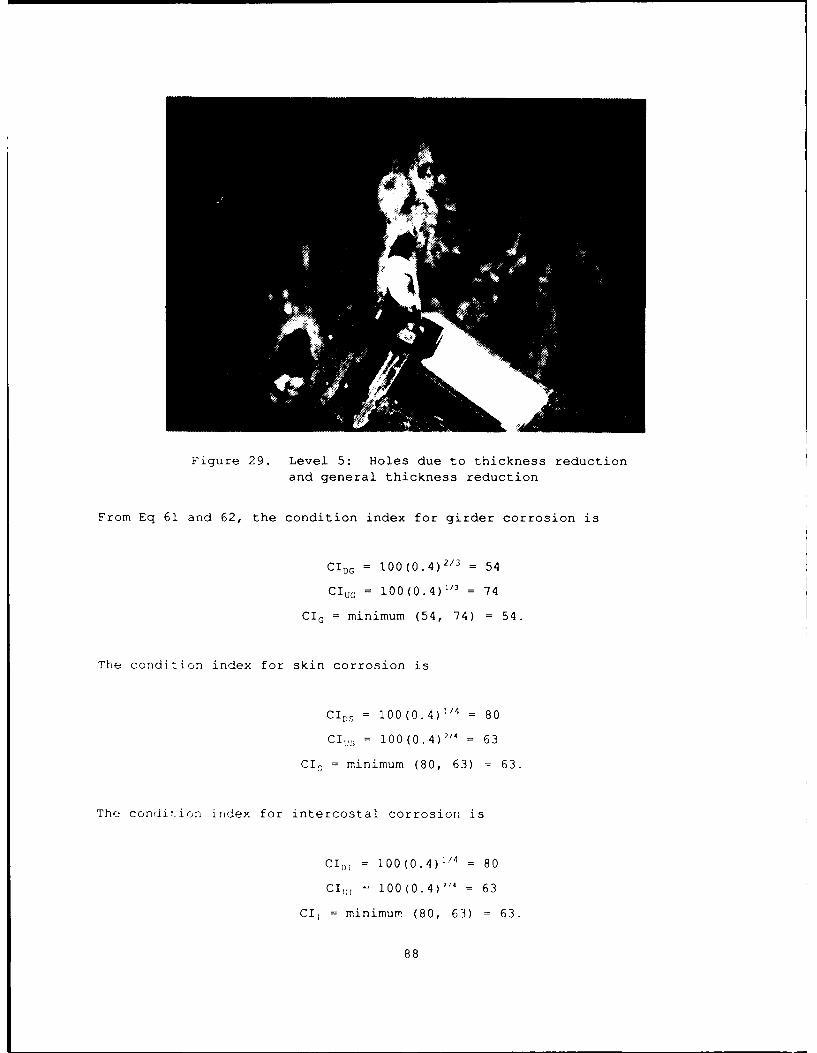
Figure 29. Level 5: Holes due to thickness reductionand general thickness reduction
From Eq 61 and 62, the condition index for girder corrosion is
CI,, = 100 (0.4)"/3 -54
CIUG = 100 (0.4)"3 74
GIG = minimum (54, 74) = 54.
The condition index for skin corrosion is
CID, = 100(0.4)'" = 80
CI.,, = 100(0.4 )2/4 = 63
CID = minimum (80, 63) = 63.
The condition index for intercostal corrosion is
CID! = 100(0.4 1" 80
CI,, 100(0.4) 114 63
Cl = minimumr (80, 63) = 63.
88

The condition index for entire corrosion over the gate leaf is
ci = MINIMUM (54, 63, 63) = 54.
Multiple Distresses
134. When several types of distress occur simultaneously, such as both
anchorage movement and offset, the condition indexes are combined into a
single value. Weighting factors are introduced to reflect the importance of
the various distresses. Hence, let wi be the weighting factor for the func-
tional condition index for Distress i. The weighting factors assign more
value to the more significant distresses. Relative initial weights are listed
in Table 5. They reflect, to some degree, the opinion of the Corps experts.
These factors also represent the opinion of the authors. The table illus-
trates that anchorage movement is the most important and dents the least
important.
135. The normalized weighting factors are defined by
W, = w,/ w, (100). (64)
Note that
1W. = 100. (65)1
Values are listed in Table 5 (rounded to add up to 100). The combined
functional condition index for all distresses is then given by
Functional CI = W CI 1 + W 2CI 2 + (66)
where the sum is for all 10 distresses.
89

Table 5
Unadjusted Weighting Factors for Distresses
Code Distress w1 W, (%)
1 Anchorage movement 11 18
2 Elevation change 9 14
3 Miter offset 5 8
4 Gaps 8 13
5 Downstream movement 7 11
6 Cracks 6 10
7 Leaks and boils 3 5
8 Dents 1 2
9 Noise, jumping, or vibration 7 11
10 Corrosion 5 8
136. During the field testing of a preliminary version of the above
rating procedure, it became clear that, as a distress became more severe, its
relative importance became larger. Thus, a variable adjustment factor was
introduced to increase the distress-weighting factor as its functional
condition index approached Zone 3 (Table 2). The adjustment factor, plotted
in Figure 30, has a maximum value of 8; that is, if a distress has a condition
index less than 40, its importance increases 8 times.
Field Testing
137. The analysis of performance of the rating rules presented in this
s(_ction is a study of the calculated functional condition index versus subjec-
tive index values determined by a group of miter lock gate expert engireers.
The expert engineers provided the guidance for establishment and selection of
distiess rule values, as well as observation ratings of the field test miter
90

10
9
8CI = 8 - 7*(CI-40)/30
70
z 5SZONE 1 o /
3
Lyj
0
DISTRESS CONDITION INDEX
Figure 30. Weight adjustment factor for subjective condition index
lock gates. The miter lock gate experts who participated in the initial rule
development were Mr. jack Sirak and Mr. Eugene Ardine (Ohio River Division),
Mr. Richard Atkinson (Rock Island District), Mr. D. Wayne Hickman, and
Mr. Lynn Midget (Nashville District).
138. The inspection and rating procedure described in this report has
been applied in three field tests. In A~ugust 1988 a preliminary procedure was
applied to the lower lock gate at Lock and Dam 19 in Keokuk, Iowa. Four US
Army Corps of Engineers experts were involved in this test: Ardine, Atkinson,
Midget, and Hickman. Dr. Anthony Kao (USACERL project monitor) was an
observer. Lock and Dam 19, located 'rn the Mississippi River at Keokuk, IA, is
a horizontally framed miter lock gate designed and built by the US Army Corps
of Engineers in 1945. Each lower gate leaf is 51 ft tall and 62 ft wide. The
lock chamber is 1,200 ft long and 110 ft wide. The results of that field
91

test, although primarily qualitative, were used to make several modifications
to the initial version of the rating procedure.
139. In October 1988 the second and third field tests were conducted in
the Paducah, Kentucky, area by five Corps of Engineers experts:
Atkinson, Hickman, Midget, Mr. Steve Moneymaker (Barkley and Kentucky area
lockmaster), and Mr. Tom Hood (Nash:ille District Office). Kao was also
present. Two different locks and dams were inspected: Kentucky Lock and Dam
(upper and lower gates) and Barkley Lock and Dam (upper and lower gates).
Kentucky Lock and Dam, located on the Tennessee River by Kentucky Lake,
Gilbertsville, Kentucky, is a double-sk n-plate horizontally framed miter lock
gate designed and built by the Tennessee Valley Authority (TVA) about 1955.
The upper gates are 46.5 ft tall and 62 ft wide. The lower gates are 92.5 ft
tall and 62 ft wide. The lock chamber is 600 ft long and 110 ft wide.
Barkley Lock and Dam, located on the Cumberland River by Kentucky Lake,
Paducah, Kentucky, is a horizontally framed, miter lock gate system designed
and built by the US Army Corps of Engineers about 1958. The upper gates are
50 ft tall and 62 ft wide. The lower gates are 91 ft tall and 62 ft wide.
The lock chamber is 800 ft long and 110 ft wide.
140. Each expert was asked to rate the individual distresses in each
gate leaf, that is, assign a functional condition index to each distress.
Miditionally, the experts were asked to assess an overall leaf condition
index. Many of the comments and suggestions made during that test have been
incorporated into the current version of the procedure. Some adjustments to
X7x values and weighting values were made to better fit the experts' ratings.
The previous portions of Part IV include these changes.
141. The following graphs present the expert subjective index versus
the calculated functional condition index for the 10 gate leaves in the field
test. One graph is presented for each of the 10 distresses. Each graph
contains 10 groups of data, 1 group for each of the gate leaves:
ARBREVIATIONS FOR DISTRESS GRAPH COLUMNS
W'!'K'Y 1 -- KENTUCKY LOCK: LOWER RT(HT GATE
K 2 KENTUCKY LOCK: LOWER L"FT GATE
r2

KTKY 3 = KENTUCKY LOCK: UPPER RIGHT GATE
KTKY 4 - KENTUCKY LOCK: UPPER LEFT GATE
BRKY 1 = BARKLEY LOCK: LOWER RIGHT GATE
BRKY 2 = BARKLEY LOCK: LOWER LEFT GATE
BRKY 3 = BARKLEY LOCK: UPPER RIGHT GATE
BRKY 4 = BARKLEY LOCK: UPPER LEFT GATE
KEOK 1 = KEOKUK LOCK: LOWER RIGHT GATE
KEOK 2 = KEOKUK LOCK: LOWER LEFT GATE.
For example, KTKY 1 is the group of data for the right-gate, leaf of the lower
set of gate leaves at the Kentucky Lock. Within each group of ddta are four
columns of data that represent
a. the highest index assigned by an expert;
b. the lowest index assigned b" an expert;
c. the three-expert average, which is the average of the threeexperts (Atkinson, Hickman, and Midget) who participated in allthree field tests; and
d. the computer-model-calculated functional condition index.
An analysis follows of the comparison of expert rating versus the computer
model for each distress, and the overall gate leaf index.
Anchor movement: Figure 31
142. The calculated functional condition indexes of 6 of the 10 gate
leave, closely approximated the three-expert average. Of the other four
gates, the calculated condition index values for three of the gate leaves
(KTKY 2, KEOK 1, and KEOK 2) were questionable because of difficulties
encountered in making specific and accurate measurements at the dimension
points. At Lock 19, the first field test, inadeqiate apparatus prevented
accurate location of the gudgeon pin centerline. Later procedures improved
the measurements. The other calculated index value that had a wide variation
from the experts was dL BRKY 2, where excessive gudgeon pin wear was measured
but the wear was not visually apparent.
Elevation changes: Figure 32
143. The calculated functional condition indexes of 8 of the 10 gate
leaves closely approximated the three-expert average. In the other two cases,
KTKY 2 and KEOK 1, measured elevation changes were observed, calculated, and
93

MITER GATE RATING ANALYSISANCHOR UOVDAENT DISTRECSS
100
90
80
o0 7
z 3
20
10 I
(THY I K1(Y 2 KTWY 3 KTCY I E!'.Y I ORKY 2 BRKYS 3 RKY 4 KEOX I KEOK 2
Exp. Max. Exp. Min. 3 Exp. Avg. Model
Figure 31. Anchor movement distress
MITER GATE Rp-rING ANALYSISEI-VAION CHANCE OfSTRESS
100
90
80
:Cze ir: dsrs
60 -INI

rated in the upper part of Zone 2 by the computer model, whereas the experts
rated the changes in the middle of Zone 1.
Miter offset: Figure 33
144. The calculated functional condition indexes for all 10 gate leaves
closely approximated the three-expert average.
Gaps: Figure 34
145. The calculated functional condition indexes of 4 of the 10 gate
leaves closely approximated the three-expert average. Four of the remaining
index values were within 15 to 20 points of the three-expert average. In
these four cases, the experts' averages, which were in the mid-90s, suggest
that no significant gaps were present. However, the actual measurements with
the expert rules gave condition indexes in the lower range of Zone 1. In the
remaining two cases at KEOK 1 and KEOK 2, the measured gaps were partly the
result of a preliminary procedure that was adjusted for later field tests.
Longitudinal or Downstream Movement: Figure 35
146. The calculated functional condition indexes of all 10 gate leaves
closely approximated the three-expert average.
MITER GATE RATING ANALYSISOTER OFFrr DISTRES
100
90
soI ]
KTKY I ITY o3 o4 oRYtB 3 BK 4K 1
70 -S1 o I
so MI offe "I
409
Fiur 33. Mite ofse disres
to :95

MITER GATE RATING ANALYSIS5AP5 0 W.RING SURFACES DISTRESS
100
90
80 o o
z 70
z2 60
z0 0
Z 40
U2 30
20
10
0~KTKY I KlTY 2 KIrY 3 KY 4 ORKY I BRKY 2 BRKY 3 BRKY KECK I 'EOK 2
Exp. Max Exp. Min. 3 Exp. Avg. Model
Figure 34. Gaps at bearing surface distress
MITER GATE RATING ANALYSIS100
90
7o80
zo2 o70
z
0 so
P o
z
-Jz 40
Uz 30
20
10
KTXCy I K"(Y2 KTYY3 (TXY 4 SR1<YI BRKY 2 OR.1CI3 NRNYA 4 EOK I '(EOKZ2
Exp. Max. Exp. Min. 3 Exp. Avg. Model
Figure 35. Downstream movement
96

Cracks: Figure 36
147. The evaluation of cracks, which are another distress, was added
to the model after the Lock 19 test. The experts rated cracks on only 4 of
the 10 gate leaves; in those cases, the calculated functional condition index
closely approximated the three-expert average. In the remaining six cases,
the computer model calculated a 100 because no cracks were observed.
Leaks and Boils: Figure 37
148. The calculated functional condition index of 6 of the 10 gate
leaves closely approximated the 3-expert average for 2 other cases, BRKY 3 and
4, minor leaks at the lower sill seal on the upper gate set were recorded as
boils. These leaks became apparent as the chamber water level dropped below
the upper miter sill. If the minor leaks had not been recorded as boils, the
calculated index value would have been very close to the experts' rating.
However, the authors think it appropriate and necessary to record the leak in
this manner. The remaining two cases, KEOK 1 and 2, were very severe leakage
conditions and the experts and the computer model both rated the condition
severely, that is, in Zone 3, but to a different degree.
MITER GATE RATING ANALYSIS
'00
90
70
oo o
o 5o
U!
20
"I o
0 0 -o o
1KVI KKY 2 KTIe3 XWY4 RKYI AKY 2 ICY 3 RKY6 KEOK I KEOK2
Exp. Max. Exp. Min. 3 Exp. Avg. Model
Figure 36. Crack distress
97
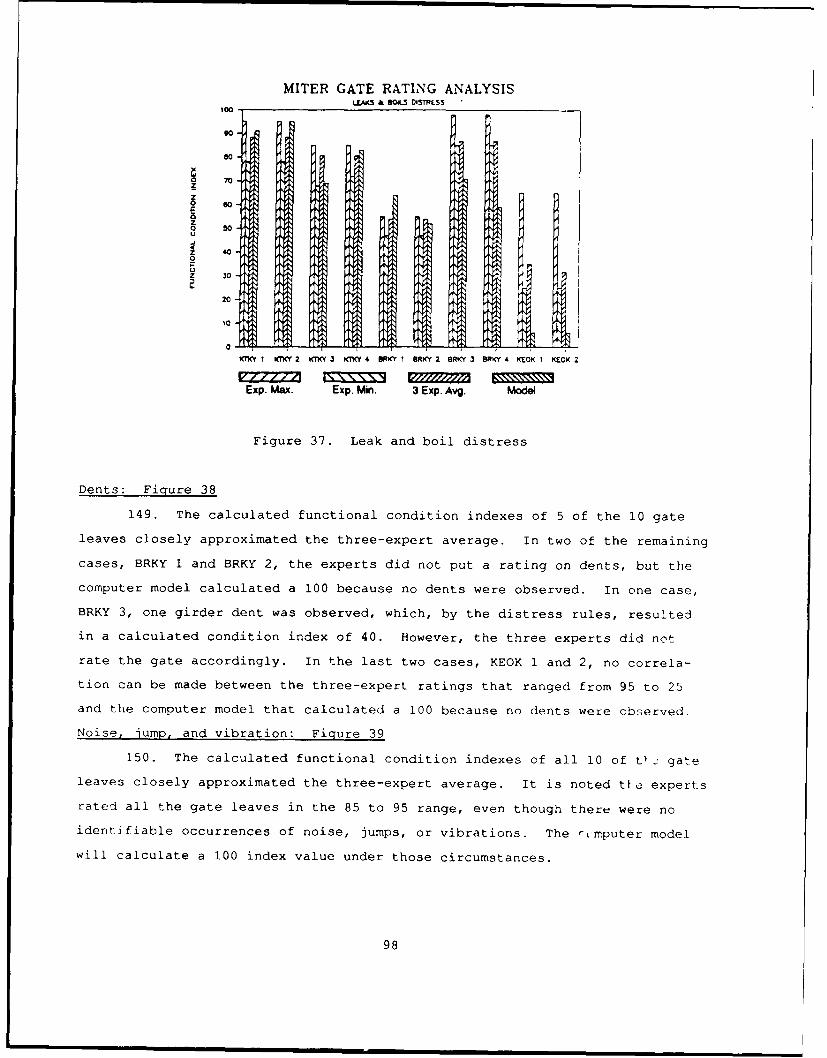
MITER GATE RATING ANALYSISLLA(S & OILS DISTRESS
100
o o0
80
0 -0Z
z
SIoz 440-
20z 30
20
20 ---o( -0I oRC1 2 R o3BIC'4 1 K
0 -
XIC I KTK(Y 2 KTK 3 KTX 4 ORKY I BRKY 2 ORKY 3 ORKY 4 KEOK 1 KEOK 2
Exp. Max. Exp. Mi. 3 Exp. Avg. MoCWe
Figure 37. Leak and boil distress
Dents: Figure 38
149. The calculated functional condition indexes of 5 of the 10 gate
leaves closely approximated the three-expert average. In two of the remaining
cases, BRKY 1 and BRKY 2, the experts did not put a rating on dents, but the
computer model calculated a 100 because no dents were observed. In one case,
BRKY 3, one girder dent was observed, which, by the distress rules, resulted
in a calculated condition index of 40. However, the three experts did not
rate the gate accordingly. In the last two cases, KEOK 1 and 2, no correla-
tion can be made between the three-expert ratings that ranged from 95 to 25
and the computer model that calculated a 100 because no dents were observed.
Noise, jump, and vibration: Figure 39
150. The calculated functional condition indexes of all 10 of t _ gate
leaves closely approximated the three-expert average. It is noted tL2 experts
rated all the gate leaves in the 85 to 95 range, even though there were no
identifiable occurrences of noise, jumps, or vibrations. The rmputer model
will calculate a 100 index value under those circumstances.
98

MITER GATE RATING ANALYSIS
90
o o7I
z oo2 so0
z 30 o
20o
0~ -
1(C I XT(Y 2 kKY 3 ,rner4 ORKY1 I ORKY 2 IRKY 3 BRXY 4 KEOK I KEO< 2
Exp. Max. Exp. Min. 3 Exp. Avg. Model
Figure 38. Dent distress
MITER GATE RATING ANALYSISNOISE. APMJI. II VIBRATION OS&hCSS
100
o 7
I o I
o 20
200
0= -oE x.Mx x.M. x.Ag oe
Fiue3.Nie2up n virto distres
09

Corrosion: Figure 40
151. The calculated functional condition indexes of 8 of the 10 gate
leaves closely approximated the three-expert average. The remaining two
calculated indexes at BRKY 1 and BRKY 2 are evaluated at the lowest value of
Zone 2 (40) because the downstream girders were judged to have a corrosion
level of 3 (Xmax for girders) . This conservative evaluation will highlight
the corrosion problem, and a subsequent investigation may be in order. A
Level 2 rating on the girder corrosion level would yield a condition index of
54, closely approximating the three-expert average. This case illustrates the
subjective nature still inherent in the evaluation of corrosion.
MITER GATE RATING ANALYSISCORROSION DISTRES
100
9080zr
0 60
zU
.4 Ir2WTT 1¢ 4 6 I6 2 N R KC £
z s0
Z 30
20
10 -i
1~ KT1~, 2 KT<Y 3 47WY 4 SRI<Y r RKY 2 BRK~ 3 ORK-Y 4 KECX E:
Exp. Max. Exp. Min. 3 Exp. Avg. Model
Figure 40. Corrosion distress
100

Overall gate leaf ratings: Fipure 41
152. The overall gate rating by the computer model tended to track very
consistently with the three-expert average, and 9 of the 10 calculated
combined functional condition indexes closely approximated the three-expert
average. In one case, however, KTKY2, the difference was approximately 20
points. The lower rating by the computer model is directly attributable to
the low rating on several individual distresses: anchor movement, gaps, and
elevation change. These individual ratings lowered the combined index rating
as well. While the 20-point differential is significant, the authors believe
the computer model corresponds to a very reasonable degree with the experts'
judgment on all 10 gate leaves.
MITER GATE RATING ANALYSISOVEAL. RAniNGS. ALL WAES
80
z
0 0 -
o
z oo
20
10
K1C1ICT 2 K Y I(KY6 B ER1kt1 EmKt 2 BRKY J IR1(t' K IK K( 2
Exp. Max. Exp, Min. 3 Exp. Avg. Model
Figure 41. Overall ratings
101
PART V: SUMMARY AND CONCLUSIONS
Summary
153. As part of the US Army Corps of Engineers REMR program, the
project team at ISU developed an inspection and rating procedure for miter
lock gates.
i54. The inspection and rating procedure intentionally was kept as
simple as possible. The inspection requires only simple hand tools such as a
tape measure, level, dial gauge, and ruler. An inspection form was developed
for recording historical information (location, previous inspections, repair
history, etc.), structural information (cross sections, water depths, addi-
tional loadings, etc.), and distress documentation (offsets, elevation change,
corrosion, etc.). Personal computer software was written for disk recording
of inspection information.
155. A condition index is computed directly from the inspection
records. The condition index is a number scale from 0 to 100 that indicates
the current state of the structure. It is primarily a planning tool that
indicates the relative need to perform REMR work. Condition indexes below 40
indicate that immediate repair is required or, possibly, that a more detailed
inspection and reanalysis are required.
156. Two separate condition indexes make up the REMR condition index.
The structural condition index is a reasonably objective measure of the
structural safety. It is related directly to the safety factor, which is
calculated by the PC software. A functional condition index, based on the
subjective opinion of several experts from the Corps of Engineers, is also
calculated. It involves at least two considerations: (a) serviceability, or
how the structure performs its function on a day-to-day basis, and (b) subjec-
tive safety, or how, in the judgment of expert engineers, the safety of the
structure has been degraded by various distresses.
157. The inspection and rating procedure has been applied in two field
tests (August 1988 and October 1988). The results of these tests were incor-
porated into the current version of the procedure.
102

Conclusions and Recommendations
158. The inspection and rating procedure for miter lock gate structures
presented in this report has had sufficient development and testing to warrant
its distribution on a wider basis. However, it should still be considered in
a developmental stage. Many of the concepts introduced, such as the struc-
tural condition index, the functional condition index, Xmax values, and
weighting factors, should be exposed to a broader range of engineers who work
in the area. Modifications to the procedure are certainly expected;
suggestions are welcomed.
103
REFERENCES
American Institute of Steel Construction 1980. Manual of Steel Construction
(AISC), 8th Ed., AISC, Chicago, IL.
Greimann, L., and Stecker, J. 1990. "Maintenance and Repair of Steel Sheet
Pile Structures," draft Technical Report REMR-OM-106, U.S. Army Corps of
Engineers.
US Army Corps of Engineers. 1963. "Working Stresses for Structural Design,"
Washington, DC.
US Army Corps of Engineers. 1984. "Lock Gates and Operating Equipment,"
Washington, DC.
US Army Corps of Engineers. 1987. "Microsoft Version, CMINV-Miter Gate
Investigation," Washington, DC.
BIBLIOGRAPHY
Greimann, L., and Stecker, J. 1989. "Users' Manual: Inspection and Rating
of Steel Sheet Pile Structures," Technical Report REMR-OM-3, US Army Corps of
Engineers, Washington, DC.
US Array Corps of Engineers. 1988. "Criteria Specifications for and
Validation of a Computer Program for the Design or Investigation of
Horizontally Framed Miter Gates (CMITER)," Washington, DC.
US Army Corps of Engineers. 1988. "User's Guide for Design and Investigation
of Horizontally Framed Miter Gates (CMITER)," Washington, DC.
104

APPENDIX: SAMPLE COMPUTER RESULTS
1. Computer programs associated with inspection procedures and record-
keeping were developed on a personal computer. At some later date, various
modules of the completed system will be integrated into a much larger mainte-
nance management system currently under development by the US Army Corps of
Engineers. However, during the initial testing period, the maintenance man-
agement program presented here was set up to operate as a stand-alone system.
This system includes modules for forms generation, data input procedures,
evaluation of condition index, and report writing.
2. The program is designed to operate on an IBM-compatible microcom-
puter with an MS-DOS operating system. The main program is written in C
language that drives two FORTRAN-77 modules.
3. The structure of the project files is organized under the DOS direc-
tory and subdirectory system. The civilian work projects constitute the
highest level, and many miter lock gate structures can be grouped under this
project directory at a second level. Under each structure, data files per-
taining to that structure and specific inspection data are in a third level of
files. This file-handling system allows the grouping of separate inspections
under the same work project.
4. Once the program is started and the project file structure is set
up, the program is menu driven. In other words, all operations, including
file management, operation selection, and report writing, are controlled from
the main menu. Other menus further direct options.
5. After the program has been installed, the user begins by keying the
responses entered on the inspection sheet. The computer monitor is set up to
look like the inspection sheet so entries follow line by line. Several edit-
ing features are available for correcting or updating. Pages 1 through 9 can
be printed as part of a report. Once all data have been entered, at the
user's request the program will calculate the functionel and the structural
ccndition index by appropriate menu selections. A SUMMARY REPORT, page 10,
which gives the condition indexes and summarizes the problems associated with
this structure, can also be printed. The example forms in this report are
presented again along with the computer-generated forms and SUMMARY REPORT.
Al

Miter Gate Structure: 8ARKLEY - UPR GATE Tue Apr !! 1QRq
MITER data sheet I
NAME OF CIVIL WORKS PROJECT:
1 : ARKLEY LOCK & DAM
(2): UPPER GATE
"ATION OF CIVIL WORKS PROJECT:
(1): BARKLEY GATE
2) : GRAND RIVER, KY.
," OF INSPECTION : 10/25/88
:NSPECTED BY . GREIMANN, STECKER, RENS
: D :
1. Upper Gate
2. Lower Gate
GATE ID (no.) : 1
,_,, OF FRAMING PRESENT:
1. Horizontal
2. Vertical
STRUCTURE TYPE(no.) : 1
0c OF PINTLE:
. Floating
PINTLE SYStEM(no.) : 1
'- OF SKIN PLATE:'Single
2. OouoleSKIN TYPE(no.) : 1
*.L.:N6TH OF LOCK CHAMBER(ft) : 800
, TH OF LOCK CHAMBER(ft) : 110
HT OF GATE LEAF(ft) : 50A7E WIDTH : 61.75
POOL LEVELS UPPER POOL(ft) LOWER POOL(ft)
NT POOL WATER LEVELS : 357.1 3C3.3
; LOW WA-ER LEVEL : 354 300H:H ,A ER LEVEL 370.9 3a7.3
' OU RCU7INELY DEWATER THE LOCK CHAMBER I Y/N) ''33E3, vNH4T YEAR WAS THE LO( 193 3EWATEPED? : 9.3
S-';RVAL PERIOD 9
'r4 1<RUCTION DATE 1936
A2

Miter Gate Structure: BARKLEY - UPRGATE Tue Apr 11 1989
MITER data sheet 2
ARE THE ORIGINAL GATE LEAVES CURRENTLY IN PLACE (*Y/N)? YES
*If not, identify current gate leaf history:
ARE DRAWINGS AVAILABLE FOR GATE LEAVES IN PLACE (Y/N)? YES
ARE THE DRAWINGS INCLUDED WITH THIS FILE (Y/N)? NO
PAST 10 YEAR HISTORY OF:
MAJOR MAINTENANCE, REPAIRS, OR OTHER MODIFICATIONS.Date Description ('X' to stop, 'Z' to delete current line)
PREVIOUS INSPECTION OR REVIEWS.Date Description ('X' to stop, 'Z' to delete current line)
==> DENT IN STEEL FENDER
TYPE OF FENDER PROTECTION AND CONDITION OF FENDERS:( 'X' to stop, 'Z' to delete current line)
==> DENT IN STEEL FENDER
TYPE OF WALKWAY ON GATE LEAF AND CONDITION OF WALKWAY:('X' to stop, 'Z' to delete current line)
OTHER COMMENTS('X' to stop, 'Z' to delete current line)
A3

Miter Gate Structure: BARKLEY - UPR GATE Tue Apr 11 1933
MITER data sheet '
FACING DOWNSTREAM AT UPPER GATE, IDENTIFY LEAF
"3 LAND OR RIVER SIDE
LEFT GATE LEAF = LAND
RIGHT GATE LEAF = RIVER
OPENING AND CLOSING OF GATE LEAVES
Left Gate(RG) Closed Right Gate(LG) Closed(Y/N) 25 50 75 100 (Y/N) 25 50 75 100
0(0 THE DIAGONALS FLAP? : Y 0 Y 0
DOES THE GATE JUMP? : N - N
13 THERE GATE NOISE? : N N''V3 THE GATE VIBERATE?: N N
ELEVATIONS OF GATE LEAF
Near Miter Miter
Left leaf Recessed Miter 1' head Full head
)uoin : 4.46 4.47 4.47 - 4.47
Miter : 4.51 4.54 4.55 4.53
r)r leafuoin : 4.46 4.47 4.47 4.48
Miter : 4.53 4.56 4.55 4.54
ANCHORAGE SYSTEM MEASUREMENT
Is the Concrete Cracked or Spalled at Location 4?
Left gate Right gate
S.--aIleI(Y/N) : N YPze'endicular(Y/N) : Y Y
Le - gate Near Miter MiterArm Dim.(in) Recessed Miter 1' head Full heaO
Parallel 4 :0.438 0.438 0.440 .441
>arallel 5 : 43.125 43.125 43.125 43.125
P.=rallel 6 : 12.875 12.813 12.813 12.8130 erpendicular 4 : 0.324 0.319 0.318 0.320:erpendicular 5 : 24.5 24.563 24.563 24.5
Perpendicular 6: 18.563 18.563 18.563 'c.563
rit gate Near Miter Miter
Arm Dim.(in) Recessed Miter 1' head Fu 1 I 'I ac0 rallel 4 : 0.345 0.347 0.348 0. 34
3rq~lel 5 :43.375 43.375 43.375 4:. :9r i e 6 : 12.625 12.563 12.563 12.5
-?.ndicular 4 0.193 0. 193 0. 194 '. j 9-rpendicular 5 : 20.25 20.25 20.25 20.156
-. pndictj ,ar 6 : 21.75 23 . 3 3 21 .815 2 . 375
A4

Miter Gate Structure: BARKLEY - UPRGATE Tue Apr 11 1989
MITER data sheet 4
OFFSET OF MITER BLOCKS WITH GATES AT MITER (1'HEAD), (Dim. 1 Fig. 1)
Location Measurement(in) Walkway distance(ft) Gate downstream
Top : .25 3.75 L
DSWL : 0 24 L
DSWL : Down stream water level
GAP BETWEEN BEARING BLOCKS AT MITER (1'HEAD), (Dim. 2, 3-Fig. 1)
Location Measurement(in) Walkway Disatnce
Left quoin @ Top 0 6
Left quoin @ DSWL : .0157 26Right quoin @ Top : 0 6Right quoin @ DSWL : .0396 26
Miter @ Top : 0 3.75
Miter @ DSWL : 0 26
LONGITUONAL POSITION OF MITER POINT (Dim. 10 Fig. 1)Measurement (in)
Location 1'head Full head Walkway distance(ft)
Top : 4.875 4.5 3
DSWL : .875 1.25 24
LOCK CHAMBER FILLING (OR EMPTYING)
Does the gate vibrate?
Left gate(Y/N) : Y
Right gate(Y/N) : Y
DOES A LEAK FOLLOW THE RISING (OR EMPTYING)
WATER LEVEL AND THEN CLOSE AS THE WATER
CONTINUES TO RISE (EMPTY)?
Left Quoin (Y/N) : NMiter (Y/N) N
Right Quoin (Y/N) : N
OOES THE GAP BETWEEN MITER BLOCKS CHANGE?
(Y/N) : Y
If yes, select from the following choices the
most accurate description of the change.
1. Top gap initially open but closes under full head.
2. Top gap opens wider but closes under full head.3. Top gap opens and remains open.
4. Top of miter is closed but gap opens between water line and top.
5. Top of miter is closed and gap between water line and top closes.
Choice No. : 4
Estimate the maximum width of gap (in) : .3
Estimate the location of the maximum
gap from the walkway kft) : 14
A5

Miter Gate Structure: BARKLEY - UPR GATE Tue Apr 11 1989
MITER data sheet 5
OBSERVArIONS FROM BOAT
CORROSION AT SPLASH ZONE (LEVEL 0,1,2,3,4, OR, 5)
Left Gate(LG) Right Gate(RG)
Up Stream Down Stream Up Stream Down S'ream
SPin :1 1 1
Girder :1 1 1Ir tercostal 1 1 1 1
OFNTS -- SKIN PLATE(S), GIRDERS(G), OR INTERCOSTALS(I)
Gate Component Location, Distance From: Size (rt)
; -r LG S, G, or I Walkway (ft) Quoin (ft) Heignt Aid-
RG G 15 58 1 .
A -CKS -- SKIN PLATE(S), GIRDERS(G), OR INTYERCOSTAL(I)
,ate Component Location, Distance From: Size (ft)
or LG S, G, or I Walkway (ft) Quoin (ft) Leng I-
3EaRING BLOCK LEAKS @ LEFT (L), MITER (M), or RIGHT (R)
Type R,M,L Distance From Walkway(ft) Length(ft,
R 40 .5
= M 28 .25
M 61
L 40
'7(IN LEAKS @ LEFT (L) OR RIGHT (R)
(Gate Type Shortest Distance From
So)r L Hor(H) or Vert(V) Walkway(ft) Quoin(ft)
C:CLS - LEFT (L), RIGHT (R) OR MITER (M)Typ (R,L or M) Distance from Quoin(ft)~== M 61
40
A6

Mite," lire Structure: BARKLEY -- UPR GATE Tue Apr 1 1 1989
MITER data sheet 6
CALCULATION DATE :10/25/88
CALCULATED BY : RENS
REQUIRED OVERALL GEOMETRY -- (Fig. 12)
Positive elevation of sill above any datum, ELSILL (ft): 333Sill to bottom of skin plate, GBOT (ft): .75s3ll to overflow elevation at top of gate, GTOP (ft): 44.75
REQUIRED OVERALL LEAF GEOMETRY -- (Fig. 12)
Leaf between contact points. GLENG (ft): 623,ate leaf slope, GSLOPE: 3
Center of gudgeon pin to down stream edge of girder webs,GWORKL (ft): .375
Quoin contact point to gudgeon pin, GQUOIN (ft); 1.98Working line to gudgeon pin (positive when contact point is.Jownstream from gudgeon), GPIN1 (ft): 1.25
COMMON GIRDER GEOMETRY DIMENSIONS -- (Fig. 12)
Girder web depth, GWEBD (in.): 84
Quoin contact point to center of nearest end diaphragm alongworking line, DQPED (in.): 48
Center of end diaphragm at miter end of gate to mitercontact point along working line, DEDMP (in.): 48Bottom girder downstream flange extension belowweb centerline, BGDFD (in.): 3
GIRDER ELEVATIONS -- (Fig. 12)
Number of girders in the gate leaf, NOIRDS: 11Girder Number, NGIRD Vertical Distance above sill, VD(ft)
==> 1 44.75
> 2 40.75==> 3 36.25
==> 4 31.75
==> 5 27.25
==> 6 22.75==> 7 18.25
8 13.75= g 9.25
== 10 5.25
=> 11 .75
A7

Miter Gate Structure: BARKLEY - UPR GATE Tie Apr '1 '98
MITER data sheet 7
GIRDER DIAPHRAGM SPACING -- (Fig. 14)
Top girder Bottom girder Space between Intercostal spacesof similar pnl of similar pnl end diaphragms betweet- adjace-:t
diagrapnns
NPANLI NPANLN NDS NIS
-=> 1 11 4 6
,- EAD AND LIVE LOADS:
idditional Jead load, including ice, mud, wal iway, gusset p a- ,
etc, ADEAD (lbs): 6642
Quoin contact point to centroid of ADEAD along workingline, XDEAD (ft): 31
Downstream edge of girder web to centroid
of ADEAD, ZDEAD (in.): 0?&,oyancy force of acting on dry weight of gate, ABUOY (Tbs. ): 3,%,2
Quoin contact point to centroid of ABUOY along workingline, XBUOY (ft): 31
Downstream edge of girder web to centroid of ABUOY. ZBUY Un.): 2'Applied live load, including walkway and bridgeway, ALlvE ('tb : .
R'EQUIRED WATER ELEVATIONS -- (FEET ABOVE EL'rLL)
Elevation o upper pool, ELUP (ft): 375
Elevation of lower pool, ELLP (It): 302'=ull submergence elevation, ELFS (ft): 378.125
,2perating water elevation, ELOW (ft): 375
3Y7EL YIELD STRENGTH (KSI):
Mirc. Nebs Flanges sk-n==,36 36 36 36
TEiffners Intercostals Quoin Diaphragns
36 36 25
A8

Miter Gate Structure: BARKLEY - UPR GATE Tue Apr 11 1989
MITER data sheet 8
3 IRDER WEB THICKNESSES (in.) -- (Fig. 14)
Groups of similar girders Web end zone Web center zoneTop girder Bottom girder thickness thickness
NGIRDI NGIRDN GWET GWCT
1 1 .5 52 7 .5 .5
== 8 9 .625 .625
==> 10 10 .75 .75
==> 11 11 1 1
GIRDER FLANGES, UPSTREAM (in.) -- (Fig. 14)
Groups of similar girders Upstream flange widthsTop number Bottom number
NGIRDI NGIRON GUFEW GUF34W GUF4Cv
1 5 9 9 9== 6 6 10.5 10.5 10.5
7 7 12 12 128 8 12 12 129 10 15 15 1511 11 16 16 "5
Upstream flange thickness Upstream flange cover plateDist from quoin Width Thickness
GUFET GUFCT GUCPX GUCPW GUCPT1 0 0 0
1 0 0 01 0 0 0
==>1.25 1.25 0 0 0
==>1.25 1.25 0 0 0
2 0 0 0
.[IROER FLANGES, DOWNSTREAM (in.) -- (Fig. 14)
Groups of similar girders Downstream flange widthsTop number Bottom number
NGIRDI NGIRDN GOFEW GDFCW1 1 9 92 5 9 9
6 7 9 9.8 10 9
11 11 12 12
Oownstream flange thickness Downstream flange cover plateDist from quoin Width T:jickneq
GDFET GDFCT GDCPX GDCPW==-.75 .75 0 0 1)
==>.75 .75 0 0 0==,.75 .75 0 0 0
1 0 0 01 0 0 0
A9

Miter Gate Structure: BARKLEY - UPRGATE Tue Apr 11 1989
MITER data sheet 9
GIRDER FLANGE COORDINATES (ft) -- (Fig. 14)
Group of similar girders Splice plate distance from quoin
Top number Bottom number Upstream Downstream
NGIRDI NGIRDN GUFX4 FDFX5
11 144 144
GIRDER WES STIFFNERS (in.) -- (Fig. 14)
Group of similar girders Number of trans. Number of long
Top number Bottom number stiffener spaces stiffener pairs
NGIRDI NGIRDN NGWTS NGLS
2 9 2 1
==> 10 10 1 1
==> 11 11 0
Longitudnal stiffener geometry
Stiffener number 1 Stiffener number 2
Width thickness Width thickness
GLS1D GLS1W GLSIT GLS2D GLS2W GLSIT
-4 -4 .5 0 0 0
==>4 -5.5 .5 0 0 0
==,41 -5.5 .5 0 0 0
Stiffener number 3
Width thickness
,GLS3O GLS3W GLS3T
0 0 0
0 0 0
0 0 0
T1 TERCOSTAL AND SKIN PLATE GEOMETRY (in.) -- (cig. 14)
Group of similar intercostals
7 p gir-der number Bottom girder number Skin plate thickness
NPANLI NPANLN SPT
1 5 .375
-- 7 11 .5
D'gPth (perp to skin) Stem thickness Flange Width Flange T~-ickres
ODI STEMT FWI
6 .5 0 0
:= 7 .5 0 0
A1O

Miter Gate Structure: BARKLEY - UPRGATE Thu Apr 13 1989
SUMMARY REPORT
PROJECT NAME:BARKLEY LOCK & DAM
UPPER GATE
1-CCAT ION:
BARKLEY GATEGRAND RIVER, KY.
INSPECTION DATE: 10/25/88
,NSPECTED BY: GREIMANN, STECKER, RENS
FUNCTIONAL CICondition Index Right Gate Left Gate
ANCHOR SYSTEM : 60 71LONG. MOVEMENT : 74 74NOISE JUMP : 100 100OFFSET CI : 65 65GAP CI : 85 94CORROSION : 74 74DENTS : 40 100.RACKS . 100 100L A<S & BOILS : 70 58ELEVATION : 83 69
COM1NED CI 70 76
STRUCTURAL CI
Lc INTERCOSTAL PNL 4 SKIN PNL 4 GIRDER GRDR 4 MINIMUM
1 100. 10 100. 10 49. 7 49.2 100. 10 100. 10 77. 7 77.
100. 2 100. 2 100. 3 100.100. 2 100. 2 100. 3 100.100. 10 100. 6 74. 7 74.
STRUCTURAL CI 49.
CORROSION MODIFIED STRUCTURAL CI -- RIGHT GATEINTERCOSTAL SKIN GIRDER MINIMUM
93.00 85.00 36.00 36.00
CORROSION MODIFIED STRUCTURAL CI -- LEFT GATEINTERCOSTAL SKIN GIRDER MINIMUM
9,.0,) 09.')00 36.00 36.00
All