DSX-1040 Series Hardware Installation Manual September … · in accordance with the National...
214
® DSX-1040 Series Hardware Installation Manual September 2014
Transcript of DSX-1040 Series Hardware Installation Manual September … · in accordance with the National...

®
DSX-1040 Series Hardware Installation Manual
September 2014

ii
Compliance Information This equipment was tested and found to comply with the limits for a Class A digital device, pursuant to part 15 of the FCC Rules. These limits provide reasonable protection against harmful interference when the equipment is operated in a commercial environment. This equipment generates, uses, and can radiate radio frequency energy. Not installing this equipment in accordance with this instruction manual, may result in harmful interference to radio communications. Operation of this equipment in a residential area is likely to cause harmful interference in which case the user will be required to correct the interference at their own expense. You must consult your local fire codes before installing any locking device on doors, gates, or barriers. A construction and fire approval permit may be required before installing any equipment. Call your local Fire Marshall for building code requirements in your area. For UL installations, you must install the DSX System according to the UL Installation Manual and in accordance with the National Electric Code, ANSI / NFPA 70 regulations and recommendations for US Installations. Canadian installations must be in accordance with the Canadian Electric Code C22.1. The DSX-1022, DSX-1040CDM, DSX-1040PDM, DSX-1042, DSX-1043, DSX-1044, DSX-CKI-C, DSX-CKI-K, DSX-DP485 and DSX-FRB8 have been tested and found to conform to the requirements of UL 294. The DSX-1022, DSX-1040CDM, DSX-1040PDM, DSX-1042, DSX-1043, DSX-1044, DSX-1040-PE-B, DSX-MCI, DSX-LAN, DSX-SPS and DSX-2PC have been tested and found to conform to the requirements of UL 1076. The following card readers have been tested by UL for compatibility with DSX equipment: Essex DS-12, HID ID-MP5365, HID W-S, Mercury MR-10, Motorola ASR-503 and TimeKeeping Systems TKS-110. Information contained within this document was known to be true at the time of printing. This information is subject to change any time without notice. DSX is a registered trademark of DSX Access Systems Inc, WinDSX is a trademark of DSX Access Systems Inc. The use of or reference to specific Company names or products within this document may or may not be the registered trademarks of the respective companies. This document is a team effort by the Technical Support and Engineering Group at DSX Access Systems, Inc. All DSX manufactured products are warranted against defects in materials and workmanship for two (2) years from date of shipment. Products not manufactured by DSX are warranted for one (1) year. DSX Access Systems, Inc., will repair or replace products that prove defective and are returned to DSX freight prepaid within the warranty period. The foregoing warranty shall not apply to defects resulting from misuse, accident, alteration, neglect, improper installation, unauthorized repair, or Acts of Nature. DSX shall have the right of final determination as to the existence and causes of the defect. No other warranty, whether written or oral is expressed or implied.

iii
Table of Contents System Overview ............................................................................................................................................................... 1 Typical System Configuration ........................................................................................................................................ 3 1040 Series Controller Architecture ............................................................................................................................... 4 1040 Series Controller and Module Placement .............................................................................................................. 5 Cable Specifications ........................................................................................................................................................... 6 UL Requirements ............................................................................................................................................................... 8 Controller Tamper .......................................................................................................................................................... 8 External Power-On Indicator .......................................................................................................................................... 8 Battery ............................................................................................................................................................................ 8 Readers ........................................................................................................................................................................... 8 Exhaust Fan .................................................................................................................................................................... 8 1040PDP Power Distribution Panel ................................................................................................................................... 9 1040PE Enclosure Specifications ................................................................................................................................. 10 Typical Configuration .................................................................................................................................................. 11 SWS150 Power Supplies .............................................................................................................................................. 12 100 - 240VAC Connections ......................................................................................................................................... 12 Grounding ..................................................................................................................................................................... 12 SWS150 Power Supply Mounting ................................................................................................................................ 13 SP150 Power Supply Mounting ................................................................................................................................... 13 SP150, SP320 Power Supplies ..................................................................................................................................... 14 115 - 240VAC Connections ......................................................................................................................................... 14 Grounding ..................................................................................................................................................................... 14 AS150 Power Supplies ................................................................................................................................................. 15 115 - 240VAC Connections ......................................................................................................................................... 15 Grounding ..................................................................................................................................................................... 15 PDP Exhaust Fan Mounting ......................................................................................................................................... 16 Power Connections from Power Supplies to DSX-PDM (Rev 9 PDM) ...................................................................... 17 Power Connections from DSX-PDM to DSX-CDM (Rev 9 PDM) ............................................................................ 17 Battery Connections on the DSX-PDM (Rev 9 PDM) ................................................................................................. 17 Battery Voltage Selection for Lock Power (Rev 9 PDM) ............................................................................................ 17 Battery Test Input (Rev 9 PDM) .................................................................................................................................. 17 Battery Requirements (Rev 9 PDM) ............................................................................................................................. 17 Fire Override Input (Rev 9 PDM) ................................................................................................................................ 18 Fire Override Output (Rev 9 PDM) .............................................................................................................................. 18 Jumpers J3-J10 (Rev 9 PDM) ....................................................................................................................................... 18 AC Power Loss Output (Rev 9 PDM) .......................................................................................................................... 18 Low Battery Output (Rev 9 PDM) ............................................................................................................................... 18 Load Shed Jumper (Rev 9 PDM) ................................................................................................................................. 18 Fuse Locations and Ratings (Rev 9 PDM) ................................................................................................................... 19 Diagnostic LEDs (Rev 9 PDM) .................................................................................................................................... 19 Lock Output Wiring (Rev 9 PDM) ............................................................................................................................... 19 Power Connections from Power Supplies to DSX-PDM (Rev 8 PDM) ...................................................................... 20 Power Connections from DSX-PDM to DSX-CDM (Rev 8 PDM) ............................................................................ 20 Battery Connections on the DSX-PDM (Rev 8 PDM) ................................................................................................. 20 Battery Voltage Selection for Lock Power (Rev 8 PDM) ............................................................................................ 20 Battery Test Input (Rev 8 PDM) .................................................................................................................................. 20 Battery Requirements (Rev 8 PDM) ............................................................................................................................. 20 Fire Override Input (Rev 8 PDM) ................................................................................................................................ 21 Fire Override Output (Rev 8 PDM) .............................................................................................................................. 21 AC Power Loss Output (Rev 8 PDM) .......................................................................................................................... 21 Low Battery Output (Rev 8 PDM) ............................................................................................................................... 21 Load Shed Jumper (Rev 8 PDM) ................................................................................................................................. 21 Fuse Locations and Ratings (Rev 8 PDM) ................................................................................................................... 21 Diagnostic LEDs (Rev 8 PDM) .................................................................................................................................... 22 Lock Output Wiring (Rev 8 PDM) ............................................................................................................................... 22 Power Connections from Power Supplies to DSX-PDM (Rev 7 PDM) ....................................................................... 23

iv
Battery Connections on the DSX-PDM (Rev 7 PDM) ................................................................................................. 23 Battery Voltage Selection for Lock Power (Rev 7 PDM) ............................................................................................ 23 Battery Test Input (Rev 7 PDM) .................................................................................................................................. 23 Battery Requirements (Rev 7 PDM) ............................................................................................................................. 23 Fire Override Input (Rev 7 PDM) ................................................................................................................................ 24 Fire Override Output (Rev 7 PDM) .............................................................................................................................. 24 AC Power Loss Output (Rev 7 PDM) .......................................................................................................................... 24 Low Battery Output (Rev 7 PDM) ............................................................................................................................... 24 Fuse Locations and Ratings (Rev 7 PDM) ................................................................................................................... 24 Diagnostic LEDs (Rev 7 PDM) .................................................................................................................................... 25 Lock Output Wiring (Rev 7 PDM) ............................................................................................................................... 25 Power Connections from Power Supplies to DSX-PDM (Rev 6 PDM and Lower) ..................................................... 26 Battery Connections on the DSX-PDM (Rev 6 PDM and Lower) ............................................................................... 26 Battery Voltage Selection for Lock Power (Rev 6 PDM and Lower) .......................................................................... 26 Battery Test Input (Rev 6 PDM and Lower) ................................................................................................................ 26 Battery Requirements (Rev 6 PDM and Lower) .......................................................................................................... 26 Fire Override Input (Rev 6 PDM and Lower) .............................................................................................................. 27 AC Power Loss Output (Rev 6 PDM and Lower) ........................................................................................................ 27 Low Battery Output (Rev 6 PDM and Lower) ............................................................................................................. 27 Fuse Locations and Ratings (Rev 6 PDM and Lower) ................................................................................................. 27 Diagnostic LEDs (Rev 6 PDM and Lower) .................................................................................................................. 28 Lock Output Wiring (Rev 6 PDM and Lower) ............................................................................................................. 28 1042 Reader Controller Features ...................................................................................................................................... 29 Typical Field Connections ............................................................................................................................................ 30 Power and Communications ......................................................................................................................................... 31 Fuse Rating and Locations ........................................................................................................................................... 32 Diagnostic LEDs .......................................................................................................................................................... 32 Overview ...................................................................................................................................................................... 33 Reader Port ................................................................................................................................................................... 33 Relay Outputs ............................................................................................................................................................... 33 Digital/Open Collector Outputs .................................................................................................................................... 33 Inputs ............................................................................................................................................................................ 33 Device Types ................................................................................................................................................................ 33 1043 Relay Output Controller Features ............................................................................................................................ 34 Typical Field Connections ............................................................................................................................................ 35 Power and Communications ......................................................................................................................................... 36 Fuse Ratings and Locations .......................................................................................................................................... 37 Diagnostic LEDs .......................................................................................................................................................... 37 Overview ...................................................................................................................................................................... 38 Applications .................................................................................................................................................................. 38 Relay Override Input .................................................................................................................................................... 38 Programming ................................................................................................................................................................ 39 Device Type ................................................................................................................................................................. 39 Input Points ................................................................................................................................................................... 39 1044 Input Controller Features ......................................................................................................................................... 40 Typical Field Connections ............................................................................................................................................ 41 Power and Communications ......................................................................................................................................... 42 Fuse Ratings and Locations .......................................................................................................................................... 43 Diagnostic LEDs .......................................................................................................................................................... 43 Overview ...................................................................................................................................................................... 44 Alarm or Point Monitoring ........................................................................................................................................... 44 Input Status ................................................................................................................................................................... 44 Input Types ................................................................................................................................................................... 44 Device Type ................................................................................................................................................................. 44 Inputs 7 & 8 and Output 1 ............................................................................................................................................ 44 Card Reader and Keypad Time Zones .......................................................................................................................... 44

v
FRB8 Fused Relay Board ................................................................................................................................................. 45 1040E Enclosure Specifications ....................................................................................................................................... 46 1040CDM Communications Distribution Module ........................................................................................................... 47 1040CDM Typical Communications and Power Connections ..................................................................................... 48 Fuse Ratings and Locations .......................................................................................................................................... 49 Diagnostic LEDs .......................................................................................................................................................... 49 Controller Addressing ...................................................................................................................................................... 50 Switch Definitions ........................................................................................................................................................ 50 Location Address .......................................................................................................................................................... 50 Device Address ............................................................................................................................................................. 50 Typical Address Settings .............................................................................................................................................. 51 Chart of Address Settings 0-63 ..................................................................................................................................... 52 Chart of Address Settings 64-127 ............................................................................................................................ 53-54 Firmware Upgrades and Processor RAM ..................................................................................................................... 54 Inputs ................................................................................................................................................................................ 56 Characteristics .............................................................................................................................................................. 56 Status LEDs .................................................................................................................................................................. 56 Standard Inputs ............................................................................................................................................................. 56 Input 7 Door Position Switch ....................................................................................................................................... 56 Input 8 Exit Request ..................................................................................................................................................... 57 Abort Delay Time ......................................................................................................................................................... 57 Panel Tamper ................................................................................................................................................................ 57 Two, Three, and Four State Monitoring ....................................................................................................................... 58 Door Lock and Input Timing ........................................................................................................................................ 59 Connection Summary of Inputs 7&8 and Output 1 ...................................................................................................... 60 Outputs ............................................................................................................................................................................. 61 Status LEDs .................................................................................................................................................................. 61 Open/SecureStates ........................................................................................................................................................ 61 Surge Suppression ....................................................................................................................................................... 61 Digital/Open Collector Outputs .................................................................................................................................... 62 Pre-Warn Output Operation .......................................................................................................................................... 63 OX4 Output Extender ....................................................................................................................................................... 64 General Description ...................................................................................................................................................... 64 Addressing of Points ..................................................................................................................................................... 64 Jumper on OX4 ............................................................................................................................................................ 64 Mounting the OX4 ........................................................................................................................................................ 64 OX4 to 1042Wiring Diagram ....................................................................................................................................... 64 Output Extenders (Other than the DSX-OX4) .................................................................................................................. 65 General Description ...................................................................................................................................................... 65 Addressing of Points ..................................................................................................................................................... 65 Dip Switches, Firmware and Wiring ............................................................................................................................ 65 Examples of Available Outputs .................................................................................................................................... 65 DSX-1043 Output Extender ......................................................................................................................................... 66 PC Bound Direct Communications .................................................................................................................................. 67 Direct Connect RS-232 Using DSX-USB .................................................................................................................... 67 Direct Connect RS-485 Using DSX-USB & DSX-MCI .............................................................................................. 67 Direct Connect RS-232 Using Serial DB-9 .................................................................................................................. 68 Direct Connect RS-485 Using 2ea DSX-MCI .............................................................................................................. 68 PC Bound Modem Communications ................................................................................................................................ 69 Modem Operation Overview ........................................................................................................................................ 69 Phone Call Description ................................................................................................................................................. 69 Location Password ........................................................................................................................................................ 70 Modem to PC Connections ........................................................................................................................................... 70

vi
Modem LED Operation ................................................................................................................................................ 70 Modem to Controller Connections ............................................................................................................................... 71 Modem Power at Panel ................................................................................................................................................. 71 Modem Power at PC ..................................................................................................................................................... 71 Modem Dip Switches ................................................................................................................................................... 71 Telephone Line Connections ........................................................................................................................................ 71 Initial Modem Communications Proceedure ................................................................................................................ 72 To Configure the Modem in the Field .......................................................................................................................... 72 To Pre-Configure the Master for Modem Communications ......................................................................................... 72 Enclosure to Enclosure Communications ......................................................................................................................... 73 Overview ...................................................................................................................................................................... 73 Block Diagram ............................................................................................................................................................. 73 1048 Inner Enclosure Communications (Master to Slave) ........................................................................................... 74 Master to Slave Communications Wiring Charts ......................................................................................................... 75 1048 Inner Enclosure Communications (Slave to Slave) ............................................................................................. 76 Slave to Slave Communications Wiring Charts ........................................................................................................... 77 1035 Quadraplexor ........................................................................................................................................................... 78 Overview ...................................................................................................................................................................... 78 Mounting ...................................................................................................................................................................... 78 Grounding ..................................................................................................................................................................... 78 Power Requrements and Connections .......................................................................................................................... 79 Dip Switch Settings ...................................................................................................................................................... 79 Diagnostic Port ............................................................................................................................................................. 79 Communications Charts ............................................................................................................................................... 80 DSX-485T Two Channel Mux/Repeater .......................................................................................................................... 81 Description ................................................................................................................................................................... 81 Typical Applications .................................................................................................................................................... 81 Communications Charts ............................................................................................................................................... 82 KB2CW.exe Terminal Emulation / IP Comm Port Program ............................................................................................ 83 Overview ...................................................................................................................................................................... 83 To Run KB2CW ........................................................................................................................................................... 83 Valid Commands .......................................................................................................................................................... 84 To Display Current Settings ......................................................................................................................................... 84 To Change Baud Rate ................................................................................................................................................... 85 Default Baud Rates ....................................................................................................................................................... 85 Changing the Modem Initialization String in the Master ............................................................................................. 86 Modem Speaker Volume .............................................................................................................................................. 86 Resetting the Modem .................................................................................................................................................... 86 Restricting Dial-out from Controller ............................................................................................................................ 86 Leased Line Modems ....................................................................................................................................................... 87 DSX Leased Line Modems........................................................................................................................................... 87 Leased Line Characteristics .......................................................................................................................................... 87 How to Order a Leased Line ......................................................................................................................................... 87 Leased Line & Master to Slave Connections ................................................................................................................ 88 Leased Line & Slave to Slave Connections .................................................................................................................. 89 Leased Line & Quadraplexor to Slave Connections ..................................................................................................... 90 RS 232 MUX .................................................................................................................................................................... 91 Description ................................................................................................................................................................... 91 RS-232 MUX Output to Slave Panels .......................................................................................................................... 91 Input Selection Jumper ................................................................................................................................................. 91 TCP\IP Communications .................................................................................................................................................. 92 LAN Interface Module ..................................................................................................................................................... 92 Overview ...................................................................................................................................................................... 92

vii
Other Applications ........................................................................................................................................................ 92 Dial-up Modem Backup ............................................................................................................................................... 92 WinDSX Software Configuration ................................................................................................................................ 92 DSX-LAN Module Programming ................................................................................................................................ 93 Programming Through a Serial Port Connecion ........................................................................................................... 93 Cisco Switch / VLAN Applications ............................................................................................................................. 94 Example of DSX-LAN Programming .......................................................................................................................... 94 Commissioning the Module .......................................................................................................................................... 95 Resetting the DSX-LAN to Factory Defaults ............................................................................................................... 95 Wiring the DSX-LAN Module to the PC for Programming ......................................................................................... 95 Questions & Answers ................................................................................................................................................... 95 Wiring the DSX-LAN to 1040 Master Controller ........................................................................................................ 96 Wiring the DSX-LAN to 1040 Slave Controller (PC Master) ...................................................................................... 96 Wiring the DSX-LAN to PC for Programming ............................................................................................................ 96 DSX-LAN Power ........................................................................................................................................................ 96 Fiber Optic Communications............................................................................................................................................ 97 Host to Master Panel with IFS D1315 .......................................................................................................................... 97 Distances ...................................................................................................................................................................... 97 Master to Slave Using IFS D1315 ................................................................................................................................ 98 Distances ...................................................................................................................................................................... 98 Slave to Slave Using IFS D1315 .................................................................................................................................. 99 Distances ...................................................................................................................................................................... 99 DSX-1035 to Slave Using IFS D1315 ........................................................................................................................ 100 Distances .................................................................................................................................................................... 100 Slave to Slave Using CSI 5012 ................................................................................................................................... 101 Master to Slave Using American Fibertek Mx-485-4................................................................................................. 102 Slave to Slave Using American Fibertek Mx-485-4 ................................................................................................... 103 Fiber Optics Manufacturers Tech Support Numbers .................................................................................................. 103 Card Plus PIN / Card Or PIN Controlling Door on 1042 ............................................................................................... 104 Inside & Outside Reader Controlling Same Door .......................................................................................................... 105 Programming and Operation ...................................................................................................................................... 105 Man-Trap Applications .................................................................................................................................................. 106 Programming .............................................................................................................................................................. 106 Man-Trap - Connections ............................................................................................................................................. 107 Special Applications ....................................................................................................................................................... 108 Virtual Outputs ........................................................................................................................................................... 108 First Man In ................................................................................................................................................................ 108 Manager First ............................................................................................................................................................. 108 The Two Man Rule ..................................................................................................................................................... 108 Access Level Control ................................................................................................................................................. 108 Threat Level Management .......................................................................................................................................... 108 Hazmat Lockdown...................................................................................................................................................... 108 Time Zone Control ..................................................................................................................................................... 108 Time Display Module (TDM & TDM5)) ....................................................................................................................... 109 Overview .................................................................................................................................................................... 109 Application ................................................................................................................................................................. 109 Power .......................................................................................................................................................................... 109 Mounting .................................................................................................................................................................... 109 TDM Mounting Instructions ....................................................................................................................................... 110 TDM5 Mounting Instructions ..................................................................................................................................... 111 TDM Wiring .............................................................................................................................................................. 112 TDM & TDM5 Wiring on a CDM with Master Controller and Slaves ...................................................................... 112 TDM Wiring on a CDM with Slaves Only ................................................................................................................. 113 Multiple TDMs on CDM with Slaves Only ............................................................................................................... 114

viii
DSX-220 Elevator Cable Noise Filter and Data Line Extender ..................................................................................... 115 Overview .................................................................................................................................................................... 115 Power .......................................................................................................................................................................... 115 Wiegand Output ......................................................................................................................................................... 115 Clock and Data Output ............................................................................................................................................... 115 Mounting .................................................................................................................................................................... 115 Wiring Requirements .................................................................................................................................................. 115 DSX-220 Connections ................................................................................................................................................ 116 Jumper Settings .......................................................................................................................................................... 116 DSX-220 and DSX-CKI Conenctions ........................................................................................................................ 117 Card Reader Port ............................................................................................................................................................ 118 Overview .................................................................................................................................................................... 118 LED’s ......................................................................................................................................................................... 118 Power .......................................................................................................................................................................... 118 Compatibility .............................................................................................................................................................. 118 Wiring ......................................................................................................................................................................... 118 Troubleshooting .......................................................................................................................................................... 118 Amtech Readers ............................................................................................................................................................. 119 Description ................................................................................................................................................................. 119 TransCore 2110 Connections ..................................................................................................................................... 120 Device Types .............................................................................................................................................................. 120 AptiQ Readers and Keypads........................................................................................................................................... 121 Description ................................................................................................................................................................. 122 LED Operation ........................................................................................................................................................... 122 Lockout Mode ............................................................................................................................................................ 122 Sounder Control ......................................................................................................................................................... 122 Presenting or using a Proximity Card ......................................................................................................................... 122 How to Configure the Keypad for 26 Bit Operation.................................................................................................. 123 How to Reset the kaypad to Factory Default (8 Bit) Operation ................................................................................ 123 Reader Connections .................................................................................................................................................... 124 Device Types .............................................................................................................................................................. 124 BridgePoint Readers ....................................................................................................................................................... 125 Cardkey Readers ............................................................................................................................................................. 126 Tools Required ........................................................................................................................................................... 126 LED Operations .......................................................................................................................................................... 127 Lockout Mode ............................................................................................................................................................ 127 Access Denied ............................................................................................................................................................ 127 Connections and Programming .................................................................................................................................. 127 Cardkey Device Types ............................................................................................................................................... 128 Carkey Cotag Readers and CKI Modifications .......................................................................................................... 128 CKI-C & L40 Connections ......................................................................................................................................... 129 CKI-C/K & D40 Connections .................................................................................................................................... 130 CasiRusco, Checkpoint, Pyramid and Readykey Proximity Readers ............................................................................. 131 CasiRusco 94x & 97x Connections ............................................................................................................................ 131 Lockout Mode ............................................................................................................................................................ 131 Sounder Control ......................................................................................................................................................... 131 Access Denied ............................................................................................................................................................ 131 Device Types .............................................................................................................................................................. 131 Checkpoint...................................................................................................................................................................... 132 Description ................................................................................................................................................................. 132 Checkpoint Keypads to 8bit Weigand and DS400-CP ............................................................................................... 133 Application ................................................................................................................................................................. 133 Device Types .............................................................................................................................................................. 133 24 Volt Checkpoint Prox Readers and DSX-CPI Connections .................................................................................. 134 Device Types .............................................................................................................................................................. 134
ix
12 Volt Checkpoint Prox Readers and DSX-CPI Connections .................................................................................. 135 Device Types .............................................................................................................................................................. 135 Dorado Magnetic Stripe Readers .................................................................................................................................... 136 Description ................................................................................................................................................................. 137 LED Operation ........................................................................................................................................................... 137 Lockout Mode ............................................................................................................................................................ 137 Access Denied ............................................................................................................................................................ 137 Card Reader/Keypad LED Operation ......................................................................................................................... 137 D544 and D584 Connections ...................................................................................................................................... 138 D644, D740 and D780 Connections ........................................................................................................................... 138 Device Types .............................................................................................................................................................. 138 Farpointe / Pyramid Proximity and Long Range Readers .............................................................................................. 139 Lockout Mode ............................................................................................................................................................ 139 Device Type ............................................................................................................................................................... 139 Pyramid P Series Proximity Connections ................................................................................................................... 140 Long Range Receivers and Transmitters .................................................................................................................... 140 Ranger WRR-42 Connections .................................................................................................................................... 141 Ranger WRR-22 Connections .................................................................................................................................... 141 Ranger WRR-44 Connections .................................................................................................................................... 142 HID Proximity Readers .................................................................................................................................................. 143 iCLASS Connections ................................................................................................................................................. 143 iCLASS SE Connections ........................................................................................................................................... 143 multiCLASS Connections ......................................................................................................................................... 144 HID – CardKey – Northern – Additional Card Support ............................................................................................. 145 5395 Thin Line II Connections ................................................................................................................................... 146 5355 & 6030 Prox Pro Plus Connections ................................................................................................................... 147 Card Plus PIN ............................................................................................................................................................. 147 Card Or PIN ................................................................................................................................................................ 147 5365 Mini Prox Connections ...................................................................................................................................... 148 5375 Maxi Prox Connections ..................................................................................................................................... 148 HID/Sensor Engineering Wiegand Card and Key Readers ............................................................................................ 149 Description ................................................................................................................................................................. 150 LED Operation ........................................................................................................................................................... 150 Lockout Mode ............................................................................................................................................................ 150 Access Denied Indicator ............................................................................................................................................. 150 Blue Wire ................................................................................................................................................................... 150 Card Insert Reader ...................................................................................................................................................... 150 Key Insert Reader ....................................................................................................................................................... 150 HID/Sensor Reader Connections ................................................................................................................................ 151 Power .......................................................................................................................................................................... 151 Device Types .............................................................................................................................................................. 151 Indala / Motorola Proximity Readers ............................................................................................................................. 152 Description ................................................................................................................................................................. 153 LED Operation ........................................................................................................................................................... 153 Lockout Mode ............................................................................................................................................................ 153 Access Denied ............................................................................................................................................................ 153 Unitized Readers ........................................................................................................................................................ 153 Readers with Electronics Module ............................................................................................................................... 153 ASR-500, 501, 503, 110, 112, 603, 605, 610, PR10 and PR20 Connections ............................................................. 154 Card Plus PIN ............................................................................................................................................................. 154 Card Or PIN ................................................................................................................................................................ 154 Separate Green LED Control ...................................................................................................................................... 154 Sounder Control ......................................................................................................................................................... 154 Device Types .............................................................................................................................................................. 154 ASR-620+ PowerProx Connections ........................................................................................................................... 155

x
ASR-620+ PowerProx Wiring Distance Chart ........................................................................................................... 155 PowerProx .................................................................................................................................................................. 155 Separate Green LED Control ...................................................................................................................................... 155 Sounder Control ......................................................................................................................................................... 155 Device Types .............................................................................................................................................................. 155 ASR-500/600 & DS-12/ 8Bit Wiegand Connections ................................................................................................. 156 Separate Green LED Control ...................................................................................................................................... 156 Sounder Control ......................................................................................................................................................... 156 Device Types .............................................................................................................................................................. 156 Mercury MR-10/20 Magnetic Stripe Reader .................................................................................................................. 157 MR-10 Description ..................................................................................................................................................... 158 LED Operation ........................................................................................................................................................... 158 MR-20 Description ..................................................................................................................................................... 158 LED Operation ........................................................................................................................................................... 158 Card Reader/Keypad LED Operation ......................................................................................................................... 158 Lockout Mode ............................................................................................................................................................ 158 Access Denied ............................................................................................................................................................ 158 Special Wiring Information ........................................................................................................................................ 158 Reader Switch Settings ............................................................................................................................................... 158 MR-10 and MR-20 in Clock and Data Connections ................................................................................................... 159 For Wiegand Output ................................................................................................................................................... 159 Connections ................................................................................................................................................................ 159 Device Types .............................................................................................................................................................. 159 Sounder ....................................................................................................................................................................... 159 Northern NR5 Magnetic Stripe Reader .......................................................................................................................... 160 Lockout Mode ............................................................................................................................................................ 160 Device Types .............................................................................................................................................................. 160 Readykey / PAC and Easikey Readers ........................................................................................................................... 161 Description ................................................................................................................................................................. 161 Readykey / PAC or Easikey Readers and DSX-RKM Connections ........................................................................... 162 Device Types .............................................................................................................................................................. 162 Securakey Barium Ferrite Readers ................................................................................................................................. 163 Description ................................................................................................................................................................. 164 LED Operation ........................................................................................................................................................... 164 Lockout Mode ............................................................................................................................................................ 164 Access Denied ............................................................................................................................................................ 164 Retrofits ...................................................................................................................................................................... 164 Securakey Key Touch Plate Reader Connections ....................................................................................................... 165 Device Types .............................................................................................................................................................. 165 LED ............................................................................................................................................................................ 165 Grounding ................................................................................................................................................................... 165 Time Keeping Systems TKS-110 Bar Code Reader ....................................................................................................... 166 Description ................................................................................................................................................................. 167 LED Operation ........................................................................................................................................................... 167 Lockout Mode ............................................................................................................................................................ 167 Access Denied ............................................................................................................................................................ 167 IC-201 Pre-Printed Bar Code Labels .......................................................................................................................... 167 Bar Code Positioning .................................................................................................................................................. 167 TKS-110 Bar Code Reader in Clock & Data Mode Connections ............................................................................... 168 Wiegand Mode ........................................................................................................................................................... 168 Device Types .............................................................................................................................................................. 168 TKS-110 / DS-12-8C Keypad in Clock & Data Mode Connections .......................................................................... 169 Power .......................................................................................................................................................................... 169 Device Types .............................................................................................................................................................. 169 TKS-110 in ASCII Mode Connections ....................................................................................................................... 170

xi
Device Types .............................................................................................................................................................. 170 XceedID Readers and Keypads ...................................................................................................................................... 171 Description ................................................................................................................................................................. 172 LED Operation ........................................................................................................................................................... 172 Lockout Mode ............................................................................................................................................................ 172 Sounder Control ......................................................................................................................................................... 172 Presenting or using a Proximity Card ......................................................................................................................... 172 How to Configure the XF2110 Keypad for 26 Bit Operation .................................................................................... 173 How to Reset the XF2110 kaypad to Factory Default (8 Bit) Operation ................................................................... 173 Reader Connections .................................................................................................................................................... 174 Device Types .............................................................................................................................................................. 174 DSX Keypads ................................................................................................................................................................. 175 Description ................................................................................................................................................................. 176 LED Operation ........................................................................................................................................................... 176 Lockout Mode ............................................................................................................................................................ 176 Power .......................................................................................................................................................................... 176 26bit Versions DS-12-26 & DS-12-SL26 ................................................................................................................... 176 ThinLine Keypad Illumination ................................................................................................................................... 176 DS-12 Keypad and PiezoProx Reader Connections ................................................................................................... 177 Power .......................................................................................................................................................................... 177 LED Control ............................................................................................................................................................... 177 Device Types .............................................................................................................................................................. 177 DS-12 Keypad with Wiegand Output Connections .................................................................................................... 178 Description ................................................................................................................................................................. 178 Power .......................................................................................................................................................................... 178 Aux. Output ................................................................................................................................................................ 178 LED Control ............................................................................................................................................................... 178 Device Types .............................................................................................................................................................. 179 DS-12 Keypad and Clock & Data Connections .......................................................................................................... 179 Description ................................................................................................................................................................. 179 Power .......................................................................................................................................................................... 179 Device Types .............................................................................................................................................................. 179 Schlage Series III Scramble Keypad Connected to a DSX-1042 ............................................................................... 180 DS400 Interface Modules ............................................................................................................................................... 181 DSX-400IC 3 x 4 to 8 bit Clock & Data Conversion Module Connections ............................................................... 181 Application ................................................................................................................................................................. 181 Device Types .............................................................................................................................................................. 181 DSX-400IB 3 x 4 to 8 bit Wiegand Conversion Module Connections ....................................................................... 182 Application ................................................................................................................................................................. 182 Device Types .............................................................................................................................................................. 182 Chart of Connections .................................................................................................................................................. 182 DSX-400ID BCD to 8 bit Wiegand Conversion Module Connections ...................................................................... 183 Application ................................................................................................................................................................. 183 DSX-400CP Checkpoint Keypad to 8bit Wiegand Conversion Module Connections .............................................. 184 Application ................................................................................................................................................................. 184 Device Types .............................................................................................................................................................. 184 DSX-400DM Duress Module Connections ................................................................................................................ 185 Application ................................................................................................................................................................. 185 Implemenation ............................................................................................................................................................ 185 DSX-400DL Door “Lock” Latch Module Connections ............................................................................................. 186 Application ................................................................................................................................................................. 186 Operation .................................................................................................................................................................... 186 Programming .............................................................................................................................................................. 186 DSX-400DL Door “Bypass” Latch Module Connections .......................................................................................... 187 Application ................................................................................................................................................................. 187 Operation .................................................................................................................................................................... 187 Programming .............................................................................................................................................................. 187

xii
DSX-DP232 and DSX-DP485 Surge Suppression Modules .......................................................................................... 188 DSX-SMP System Monitoring Panel ............................................................................................................................. 189 Description ................................................................................................................................................................. 189 Relay Definitions ........................................................................................................................................................ 189 LED Operation ........................................................................................................................................................... 189 SMP Address Switch Setting ...................................................................................................................................... 189 SMP Panel Firmware Version .................................................................................................................................... 189 DSX-1022 SMP Comnnected to a DSX-1042 Master ................................................................................................ 190 DSX-1022 SMP Testing Proceedures ........................................................................................................................ 190 Trouble Condition Verification .................................................................................................................................. 191 Device Communication Loss/Output A-1 .................................................................................................................. 191 Consecutive Access Denied Exceeded/Output A-2 .................................................................................................... 191 Low Battery/Output B-1 ............................................................................................................................................. 191 Loss of AC Power/Output B-2 ................................................................................................................................... 191 Field Test Procedures ..................................................................................................................................................... 192 Power-UP Check ........................................................................................................................................................ 192 Reader Function Check .............................................................................................................................................. 192 Trouble Shooting ............................................................................................................................................................ 193 Cannot Communicate with Master from PC in Direct Connect Mode ....................................................................... 193 Cannot Communicate with a Modem Connect Master ............................................................................................... 195 Device Communication Losses / Missed Polls ........................................................................................................... 196 No Master to Slave Communications ......................................................................................................................... 197 Card Reader Error Messages .......................................................................................................................................... 197 Receiving Bad Card Read Messages from Card Reader ............................................................................................ 197 Receiving Parity Error Messages form the Card Reader ............................................................................................ 197 No Message from Reader when Card is Used ............................................................................................................ 198 Controller Resets when the Lock is De-Energized ..................................................................................................... 198 Output 1 will not Secure ............................................................................................................................................. 198 Output 1 only Unlocks for 1 Second .......................................................................................................................... 198 Output will not Respond to Linking Event ................................................................................................................. 198 Output 1 will not Respond to Exit Request ................................................................................................................ 199 No Battery Charger Voltage ....................................................................................................................................... 199 No 12VDC Power Output........................................................................................................................................... 199 Input Will not Set Up ................................................................................................................................................. 199 No 12VDC at PDMs Terminals 1&2.......................................................................................................................... 199 No Lock Power at 1040PDM ..................................................................................................................................... 199 Routine Maintenance ...................................................................................................................................................... 200 Conditions Which May Cause Undesired Operation ...................................................................................................... 200

DSX-1040 Hardware Installation Manual 09/2014
1
System Overview The WinDSX System is a PC based site management and monitoring system used to control and monitor personnel and input activity. By making extensive use of distributed processing, the WinDSX System integrates access control, input monitoring, and equipment control into a single system.
The WinDSX System provides different controllers that offer various combinations of card reader and keypad controls, relay outputs, and monitored inputs. The controllers will combine to provide the exact number of inputs and outputs required for the application. All DSX controllers use a fully distributed architecture with real time processing at each DSX controller. By distributing all information (time, date, valid codes, access levels, etc.), the WinDSX System provides some significant advantages.
Instant response to Card Read or Keypad Entry despite system size.
No degradation of system performance in case of communications loss. All time zones,
access levels, and holiday schedules remain operational.
No loss of transactions for system history files during communication loss. All controllers automatically switch to buffer mode and can store up to thousands of events each.
Each DSX controller represents one "Intelligent Controller" in the distributed processing network. Each controller uses an AM 186 microprocessor as its engine. Instead of all processing power centralized in one PC it is distributed throughout the system. The processing occurs near each reader, which makes the system more efficient and secure.
Information downloads to the DSX controllers through a PC. The PC is not necessary for system operation and can go off-line once the system information downloads to the controllers. The system PC is simply used as:
Terminal or Window into the system
History Data Logging Device
Data Manager

DSX-1040 Hardware Installation Manual 09/2014
2
The WinDSX System will support up to 32,000 separate access control locations from a single PC. Each system maintains it's own database and history files and may control up to 64 DSX controllers per location. DSX defines each location as one Master Controller with up to 63 Slave Controllers. Locations can be combined to create a very large local network of controllers or may be maintained separately to control up to 32,000 different buildings with up to 128 card readers and/or keypads at each building. The first controller of each location is designated as the Master. All subsequent controllers at the location are designated as Slaves. Any DSX controller may be designated as the Master by specific dipswitch settings that enable it to work as a Master controller. The Master performs all of the same functions as the Slave controllers, but is also responsible for polling Slave controllers and reporting events to the Host PC. The Master controller does not make access control decisions for the Slave controllers. It is simply the messenger for information from the controllers to the PC, and from the PC to the controllers. Each of the locations may communicate to the PC using various methods. The Master controller can be wired directly to the PC, controlled via dial-up phone modems or utilize a TCP/IP LAN connection. The Master of a modem-controlled location will automatically buffer all normal transactions until it's buffer reaches 80% of capacity. When the buffer reaches 80%, the Master controller initiates a call to the Host PC and uploads all transactions. While the Master's transaction buffer is at 80%, all Slaves automatically store their own transactions until the Master has uploaded the history to the PC. If an alarm event occurs, the Master controller initiates an immediate call to the PC to report the alarm event. Alternatively, the PC may be programmed to routinely poll each of the remote modem locations and collect the history logs automatically. The WinDSX system maintains full feature capability regardless of the style of communications with the PC. Both remote modem controlled locations and direct connect/LAN locations are capable of features such as global input to input and input to output linking, floor select elevator control, global and zoned anti-passback, HVAC control, and lighting control. All DSX controllers have a built in dead man reset timer (watchdog circuit) that will automatically reboot the processor in the event that it's operation is interrupted due to a transient surge. When the processor is reset, it automatically requests a parameter download from the Master and reboots to its proper working state. If the Master controller is reset, it automatically requests a parameter download from the PC. When the Master is a modem location, it will dial the PC via the modem and receive the parameter download automatically.

DSX-1040 Hardware Installation Manual 09/2014
3
Typical System Configuration The following diagram depicts 3 PCs connected using a Local Area Network, managing four locations. One PC is the File Server where the shared database and history files reside. The second is a Comm Server that has a direct serial port connection, a dial-up phone modem connection and a LAN connection for panel communications. The third PC is a Workstation, which at the very least has administrative only or full capabilities depending on the configuration. Location 1 is shown with a DSX-LAN(M) for a Dialup Modem Backup capability if the DSX-LAN connection fails. Location 2 is shown connecting through a DSX-Modem. Location 3 connects through a DSX-LAN module. Location 4 is connected to a Serial Port of the Comm Server PC. Location 2 includes an IN plus an OUT reader along with a Time Display Module to allow the collection of Time and Attendance Reports. Location 3 includes elevator control. This is just a few of the application possibilities.
DSX-Modem
DSX-LAN(M)
Note /// A Master can be up to 50 feet away when using RS-232. RS-485 allows up to 4000 feet of communications cable between Comm-Server and Master or between panels.
Location 1
1042 Controller
1042 Controller
Devices0 - 3
Comm Server PC
Devices0 & 1
1022(Slave)
Devices2 & 3
1022
(Master)
Devices0 & 1
DSX-Modem
IN OUT
1022
(Master)
Location 2
Location 4
DSX-Modem
Note /// A 1040 Enclosure could contain all components needed in a 2 cab 16 floor elevator system.
Workstation PC
Location 3
1042 Controller
1043 Controller
1043 Controller
Devices0 -7
DSX-LAN
1044 Controller
10:19
Database PC

DSX-1040 Hardware Installation Manual 09/2014
4
DSX-1040 Series Controller Architecture
The 1040 Series Controllers provide multi-controller solutions from one enclosure. The DSX-1042 Reader Controller, DSX-1043 Output Controller, and DSX-1044 Input Controller can all be used in the 1040E Enclosure. Any combination of these controllers can be utilized in unison with the DSX-1040CDM Communications Distribution Module. This module provides a RS-485 communications input and output to connect the controllers in this enclosure to other controllers in the system. It also takes the power from the DSX-1040PDP and individually fuses it to all controllers in the same enclosure.
The DSX-1040PDP can be comprised of two 115/240VAC power supplies that provide DC power to a DSX-1040PDM module for Controller Power and Lock Power. The module provides fused outputs for the Locks with battery backup charging circuits for controller and lock power.
MAGLOCK / OUTPUT 1
DOOR CONTACT / INPUT 7
READER
EXIT REQUEST / INPUT 8
Typical Door
2 DOORS PER 1042
8 MAX DOOR PER 1040E
1040E (Enclosure)
SLOT1
SLOT2
SLOT3
SLOT4
SLOT5
SLOT6
1040CDM
POWERIN
POWEROUTCOMM
RS-232 / PC
FROM 1040PDM (15V8A)
104x MASTER
POWER INCOMM COMM IN
COMM
TO NEXT
COMM POWER IN
COMM POWER IN
COMM POWER IN
EXPANSION
SIDE A SIDE B
1042, 1043 or 1044
104x SLAVE
SIDE A SIDE B
104x SLAVE
SIDE A SIDE B
104x SLAVE
SIDE A SIDE B
1042, 1043 or 1044
1042, 1043 or 1044
1042, 1043 or 1044
Example = EXTENDER OR FRB8
1040PDP
1040PE (Enclosure)
CONTROLLER POWER SOURCE
LOCK POWER SOURCE
TO "POWER IN" OF 1040CDM
TO 15v OR 28V
OUTTO 15v
OUT
100-240VAC INPUT
BATTERY(S)FOR CONTROLLERS
(OPTIONAL) BATTERY(S)FOR LOCKS
BATTERY(S)FOR CONTROLLERS
(OPTIONAL) BATTERY(S)FOR LOCKS
1040-PDMREV 9
PANEL INPUT
LOCK INPUT
100-240v IN, 15v OUT 100-240v IN, 15-28v OUT

DSX-1040 Hardware Installation Manual 09/2014
5
DSX-1040 Series Controller and Module Placement The diagram below shows the 1040E enclosure on the left housing the various controllers and the specialty modules mounted at the top. The 1040PE enclosure on the right shows the placement of the power supplies, the power distribution modules and not shown are the backup batteries that would be located in the bottom of the enclosure.
Controller / Module Placement
1040PDM
Extender or FRB8
1042,1043 or 1044
1042,1043 or 1044
1042,1043 or 1044
1042,1043 or 1044
1040CDMPANEL POWER
15V
LOCKPOWER
15 or 27V
FAN

DSX-1040 Hardware Installation Manual 09/2014
6
Cable Specifications
All DSX system wiring must be done in compliance with the National Electrical Code, ANSI / NFPA 70 regulations, and recommendations for U.S. Installations. Canadian Installations must be done in accordance with the Canadian Electric Code C22.1 and require a minimum of 18 Ga. wire for all cables used. The wiring part numbers listed are for example only; use these to cross reference to another manufacturer if needed. RS-232
RS-232 communications are used from Host PC to Master controller when the Master is of the DSX-1040 Series of DSX Controllers. All RS-232 communications require 3 conductors with an overall shield and have a maximum distance of 50 feet. The recommended cable is:
PVC - Belden 8723 - 22 AWG 2 pair shielded, 50 feet max. Plenum - Belden 82723 - 22 AWG 2 pair shielded, 50 feet max.
RS-485
RS-485 is used for controller-to-controller communications. RS-485 is an optional method of communications for the PC to DSX-1040 Series Master. Two DSX-MCI Modules can be used to extend the distance to 4,000 feet between Master and Host PC. All RS-485 communications require two twisted pairs, and have a maximum distance of 4,000 feet. The recommended cable is:
PVC - Belden 9744 - 22 AWG 2 twisted pair, 4,000 feet max. Plenum - Belden 82741 - 22 AWG 2 twisted pair, 4,000 feet max.
Readers and Wiegand Keypads
Card readers and DS-400 Keypads require a 3 pair 22 or 20 AWG cable with an overall braided shield. Maximum distance from the DSX controller to the reader is 250 feet with 22 AWG wire and 500 feet with 20 AWG wire. 3 Pair cable provides: 1 pair for power, 1 pair for Data, and 1 pair for two separate LED control lines. Motorola Readers with optional buzzer require 7 conductors. If there is any question on how many conductors are required for a particular reader or keypad, reference the wiring diagram for that reader in this manual. If greater distances are required, the DSX-220 Module will provide up to 1,500 feet for Wiegand or Clock and Data type outputs with 18 AWG wire. The recommended cable is:
PVC - Belden 9942 or 8777 - 22 AWG 3 pair shielded, 250 feet max. Plenum - Belden 82777 - 22 AWG 3 pair shielded, 250 feet max. PVC - Belden 9873 - 20 AWG 3 pair shielded, 500 feet max. Plenum - Belden 83606 or 85164 - 20 AWG 3 pair shielded, 500 feet max.
Note /// All 5Volt powered Readers and Keypads that draw All 5Volt powered Readers and Keypads that draw 50ma or more should have a minimum of an 18AWG cable.
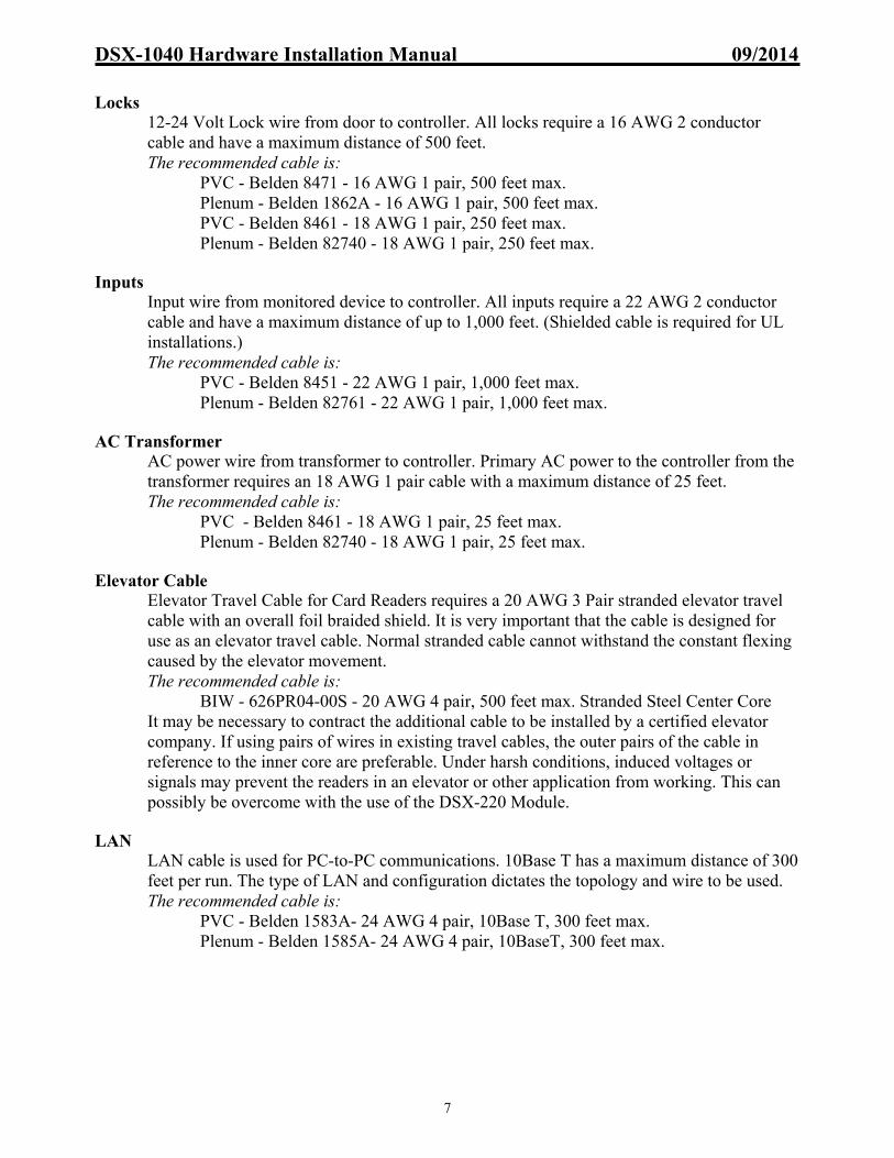
DSX-1040 Hardware Installation Manual 09/2014
7
Locks
12-24 Volt Lock wire from door to controller. All locks require a 16 AWG 2 conductor cable and have a maximum distance of 500 feet. The recommended cable is:
PVC - Belden 8471 - 16 AWG 1 pair, 500 feet max. Plenum - Belden 1862A - 16 AWG 1 pair, 500 feet max. PVC - Belden 8461 - 18 AWG 1 pair, 250 feet max. Plenum - Belden 82740 - 18 AWG 1 pair, 250 feet max.
Inputs
Input wire from monitored device to controller. All inputs require a 22 AWG 2 conductor cable and have a maximum distance of up to 1,000 feet. (Shielded cable is required for UL installations.) The recommended cable is:
PVC - Belden 8451 - 22 AWG 1 pair, 1,000 feet max. Plenum - Belden 82761 - 22 AWG 1 pair, 1,000 feet max.
AC Transformer
AC power wire from transformer to controller. Primary AC power to the controller from the transformer requires an 18 AWG 1 pair cable with a maximum distance of 25 feet. The recommended cable is:
PVC - Belden 8461 - 18 AWG 1 pair, 25 feet max. Plenum - Belden 82740 - 18 AWG 1 pair, 25 feet max.
Elevator Cable
Elevator Travel Cable for Card Readers requires a 20 AWG 3 Pair stranded elevator travel cable with an overall foil braided shield. It is very important that the cable is designed for use as an elevator travel cable. Normal stranded cable cannot withstand the constant flexing caused by the elevator movement. The recommended cable is:
BIW - 626PR04-00S - 20 AWG 4 pair, 500 feet max. Stranded Steel Center Core It may be necessary to contract the additional cable to be installed by a certified elevator company. If using pairs of wires in existing travel cables, the outer pairs of the cable in reference to the inner core are preferable. Under harsh conditions, induced voltages or signals may prevent the readers in an elevator or other application from working. This can possibly be overcome with the use of the DSX-220 Module.
LAN
LAN cable is used for PC-to-PC communications. 10Base T has a maximum distance of 300 feet per run. The type of LAN and configuration dictates the topology and wire to be used. The recommended cable is:
PVC - Belden 1583A- 24 AWG 4 pair, 10Base T, 300 feet max. Plenum - Belden 1585A- 24 AWG 4 pair, 10BaseT, 300 feet max.

DSX-1040 Hardware Installation Manual 09/2014
8
UL 294 Requirements Controller Tamper
Connect the provided Sentrol 3012 Tamper Switch to an available input on the DSX Controller. A 1K-ohm E.O.L. Resistor should be in series with one of the leads of the tamper switch on the DSX-1040 Series Controller. Program this input to be on a 24hr Time Zone so that it will be armed at all times. Give the input a name as to properly describe it, such as "Device ## Controller Door Tamper"
External Power-On Indicator
The external power-on LED must be installed in the hole marked "AC Power On" on the side of the enclosure. Run the wires through the hole from the outside to the inside of the enclosure and connect them, to terminals 13 and 14 of the DSX-CDM along with DC input wires from the DSX-PDP. The LED housing has a locking nut that will hold it into place.
Battery
At least one 12V 7AH battery is required for each DSX-1040PDP. DSX recommends the Powersonic PS-1270, the Interstate PC-1270 and the SBS S-1272. The battery capacity with one 12V 7AH battery for emergency standby is at least ½ hour with full load. To meet the additional requirements of UL 1076 each DSX-1040-PE enclosure must be have 6- 12V, 7ah batteries. Use the DSX-1040-PE-B to accommodate the amount of batteries required. Also required for UL 1076 is that of the DSX-1040-CDM, it’s “Secondary 12V, 1.5a” terminals cannot be used.
Readers UL Installations require all readers used to be UL Listed.
Exhaust Fan The exhaust fan mounts in the upper left of the DSX-1040PE enclosure. Refer to the “PDP Exhaust Fan Mounting” page for more instructions if needed.
DoorTamperSwitch
Power OnLED

DSX-1040 Hardware Installation Manual 09/2014
9
DSX-1040PDP Power Distribution Panel
Hardware Feature Quantities Description
115 / 240VAC to DC Power Supplies 2 1-115 / 240VAC to 15VDC for Controller Power
1-115 / 240VAC to 15 or 27VDC for Lock Power
Battery Charging Circuits 2 1-12VDC for Controller Power 1-12/24VDC for Lock Power – Jumper selectable
12VDC Controller Power 2 Nominal voltage 12VDC 7A max combined – battery backed up. Operating voltage range – 10-15 VDC
Supervisory Outputs 3 1- AC Loss for Panel Power, N.C. dry contacts 1- Low Battery for Panel Power, N.C. dry contacts 1- AC Loss for Lock Power, N.C. dry contacts
Battery Test Input 1 Grounding Input causes 1 minute battery load test
12 or 24VDC Fused Lock Power Outputs 8
1A individually fused outputs with connection points for lock and relay outputs. For 12V Locks the nominal voltage is 12VDC with an operating voltage range of 9 - 13.5VDC and a maximum of 1A per Output. For 24V Locks the nominal voltage is 24VDC with an operatingvoltage range of 20 - 28VDC and a maximum of .625Aper Output. Lock Outputs are Class 2 Power Limited.
Lock Override Input 1 When the Fire Override Input point sees Open circuit it drops lock power to all 8 outputs.
Lock Override Output 1 The Fire Override Output connects well with either a DSX Input for monitoring or to the next 1040PDM Fire Override Input.
TO INPUTS OF 1042
+ -+ -+ -+ -
1040PE
15 or 28VDC FROM SWS150-15/DSX or SWS150-28/DSX
15VDC TO PDMCONTROLLER
POWER
15VDC OR 28VDC
TO PDM.LOCK POWER
BATTERY TESTGND TO ACTIVATE 60 SECOND TEST
AC LOSS & LOW BATTERY
TO 1040CDM "POWER IN"
12V 7AH 12V 7AH 12V 7AH 12V 7AH
CONNECT AS SHOWN FOR 24VDC, 7AH BATTERY BACKUP OF LOCKS
CONNECT AS SHOWN FOR 12VDC, 14AH BATTERY BACKUP OF CONTROLLERS
Power Options
LOCK AC LOSS OUTPUT N.C. CONTACTS TO INPUT OF 1042 FIRE OVERRIDE OUTPUT TO NEXT PDM 31&32 OR INPUT OF 1042
100-240 VAC
SOURCE
SUPPLY N.C. DRY CONTACTS FROM FIRE PANEL / LOCK OVERRIDE
Rev 9 1040PDM
A
ELECTRICAL GROUND
100-240 VAC
SOURCE
ELECTRICALGROUND
BSEE
OPTIONSBELOW
SEE OPTIONSBELOW
SWS150-15/DSX CONTROLLER POWER
SUPPLY
SWS150-15/DSX, SWS150-28/DSX
LOCK POWER SUPPLY
= RequiredA = SWS150-15/DSX 10A Panel PowerB = SWS150-15/DSX 10A Lock Power SWS150-28/DSX 5.3A Lock Power

DSX-1040 Hardware Installation Manual 09/2014
10
DSX-1040PE Enclosure Specifications
Right1040PE Measurements
for Conduit Knock-Outs
and Mounting
Mirror Image
of Left SideBack
0.95
" 12.6
"
0.7"
14.0
"
1.75
"4.
0"
6.0"
1.375"
0.937"
Left
2.371"
14.7812
Mirror Image of Top
Bottom
15.5"
1.37
5"
0.93
7" 6.0"Top
4.0" 11.5"1.75"
13.75"
INNER
OUTER
INNER
OUTER
Conduit Sizes
1/2"
3/4"
1"
1 3/4"
Legend

DSX-1040 Hardware Installation Manual 09/2014
11
Typical 1040PDP Configuration
TO INPUTS OF 1042
+ -+ -+ -+ -
1040PE
15 or 28VDC FROM SWS150-15/DSX or SWS150-28/DSX
15VDC TO PDMCONTROLLER
POWER
15VDC OR 28VDC
TO PDM.LOCK POWER
BATTERY TESTGND TO ACTIVATE 60 SECOND TEST
AC LOSS & LOW BATTERY
TO 1040CDM "POWER IN"
12V 7AH 12V 7AH 12V 7AH 12V 7AH
CONNECT AS SHOWN FOR 24VDC, 7AH BATTERY BACKUP OF LOCKS
CONNECT AS SHOWN FOR 12VDC, 14AH BATTERY BACKUP OF CONTROLLERS
Power Options
LOCK AC LOSS OUTPUT N.C. CONTACTS TO INPUT OF 1042 FIRE OVERRIDE OUTPUT TO NEXT PDM 31&32 OR INPUT OF 1042
100-240 VAC
SOURCE
SUPPLY N.C. DRY CONTACTS FROM FIRE PANEL / LOCK OVERRIDE
Rev 9 1040PDM
A
ELECTRICAL GROUND
100-240 VAC
SOURCE
ELECTRICALGROUND
BSEE
OPTIONSBELOW
SEE OPTIONSBELOW
SWS150-15/DSX CONTROLLER POWER
SUPPLY
SWS150-15/DSX, SWS150-28/DSX
LOCK POWER SUPPLY
= RequiredA = SWS150-15/DSX 10A Panel PowerB = SWS150-15/DSX 10A Lock Power SWS150-28/DSX 5.3A Lock Power

DSX-1040 Hardware Installation Manual 09/2014
12
SWS150 Power Supplies
The SWS150-15 Power Supply accepts 100-240VAC 60 or 50Hz (auto-sensed) to provide 15VDC to the DSX-1040PDM for controller power. A separate SWS150-15 or SWS150-28 provides 15 or 28VDC to the DSX-1040PDM for 12V or 24V lock power. DSX also offers a SP320/27 that provides 27VDC and up to 11amps for lock power. Refer to the following pages for proper terminations and mounting of the power supplies.
Controller Power – SWS150-15 Lock Power – SWS150-15 or -28 100 - 240VAC 60 or 50Hz Connections
The Power Supplies requires single phase AC voltage. The circuit should be an un-switched dedicated breaker. The SWS150 automatically senses the 100VAC 60Hz or 240VAC 50Hz.
Grounding
An electrical ground provided by a 3-wire AC circuit is sufficient.
Note /// The SWS150-15 has been calibrated to provide 15.8-15.89VDC. The SWS150-28 has been calibrated to provide 29.0 – 29.5VDC. Voltage readings above the calibrated voltage may cause damage that will not be repaired under warranty. Note /// Mounting the SWS150 Power Sources is on the top of the next page.
LN
( A C
)+V
+V- V
- V
SWS150-15/DSX
LN
( A C
)+V
+V- V
- V
SWS150-28/DSX
3 Wire, Single Phase. Input 100-240VAC 2.5A 50-60Hz Ground
NeutralLine
CAUTIONRemove power before terminating or servicing.
SWS150-15/DSX
+ V
+ V
( AC )-V
-V G L N
Controller Supply Lock Supply
+ V
+ V
( AC )-V
-V G L N
1040PE
-V
-V
+V
+V L
( AC )N
SWS150-15/DSX
orSWS150-28/DSX
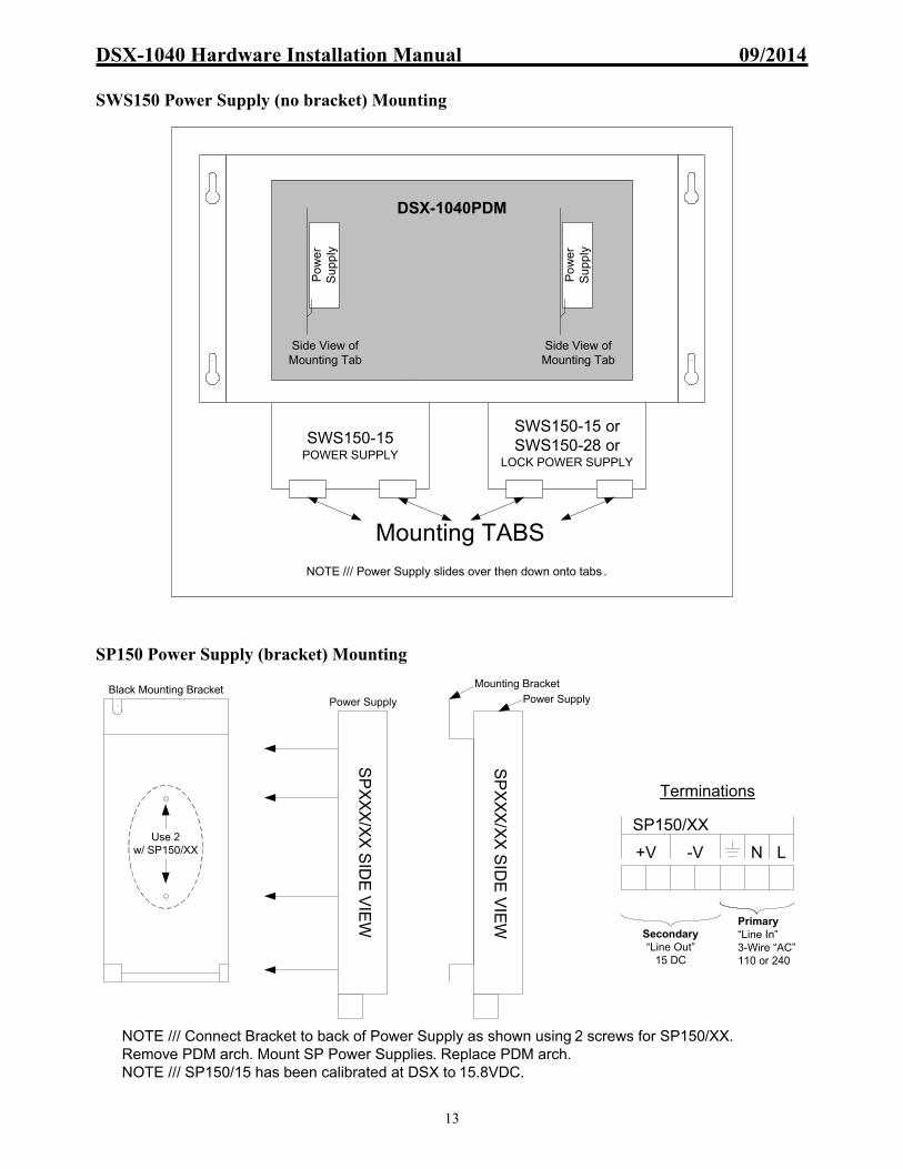
DSX-1040 Hardware Installation Manual 09/2014
13
SWS150 Power Supply (no bracket) Mounting
SP150 Power Supply (bracket) Mounting
SWS150-15 POWER SUPPLY
SWS150-15 or SWS150-28 or
LOCK POWER SUPPLY
DSX-1040PDM
Mounting TABS
NOTE /// Power Supply slides over then down onto tabs .
Side View of Mounting Tab
Po
wer
S
upp
lySide View of
Mounting Tab
Po
wer
S
upp
ly
Primary “Line In”3-Wire “AC”110 or 240
+V -V N L
SP150/XX
Secondary “Line Out”
15 DC
SP
XX
X/X
X S
IDE
VIE
W
SP
XX
X/X
X S
IDE
VIE
W
Use 2 w/ SP150/XX
Black Mounting Bracket
NOTE /// Connect Bracket to back of Power Supply as shown using 2 screws for SP150/XX. Remove PDM arch. Mount SP Power Supplies. Replace PDM arch.NOTE /// SP150/15 has been calibrated at DSX to 15.8VDC.
Power Supply
Mounting Bracket
Power Supply
Terminations

DSX-1040 Hardware Installation Manual 09/2014
14
SP150, SP320 Power Supplies
The SP Power Supply accepts 115VAC 60Hz or 240VAC 50Hz (auto-sensed) to provide 15VDC to the DSX-1040PDM for controller power. A separate SP150/15 provides 15VDC for 12V lock power or a SP150/27 provides 27VDC to the DSX-1040PDM for 24V lock power. DSX now offers a SP320/27 that provides 27VDC and up to 11amps for lock power.
Controller or Lock Power –SP150/15 or /27 Lock Power – SP320/27V
115VAC 60Hz or 240VAC 50Hz Connections
The Power Supplies requires single phase AC voltage. The circuit should be an un-switched dedicated breaker. The SP150 and SP320 automatically senses 115VAC 60Hz or 240VAC 50Hz.
Grounding
An electrical ground provided by a 3-wire AC circuit is sufficient.
Note /// The SP150/15 has been calibrated at DSX to provide 15.8-15.89VDC. The SP150/27 has been calibrated at DSX to provide 29.0 – 29.5VDC. The SP320/27 has been calibrated at DSX to provide 29-29.5VDC. Voltage readings above the calibrated voltage may cause damage that will not be repaired under warranty. Note /// Mounting the SP Power Sources is on the bottom of the previous page. Note /// Older installations may include AS150 Power Supplies. These power supplies provide terminations that differ from those shown above.
1040PE
1040PDP
3 Wire, Single Phase
115v60Hzor
240v50Hz AC
LineNeutralGround
CAUTIONRemove power before terminating or servicing.
LN( AC )G

DSX-1040 Hardware Installation Manual 09/2014
15
AS150 Power Supplies
The AS150 Power Supply accepts 115VAC 60Hz or 240VAC 50Hz (switch-able) to provide 15VDC to the DSX-1040PDM for controller power. A separate AS150/15 provides 15VDC for 12V lock power or an AS150/27 provides 27VDC to the DSX-1040PDM for 24V lock power.
Controller Power – AS150/15 Lock Power – AS150/15V or /27V
115VAC 60Hz or 240VAC 50Hz Connections
The Power Supplies requires single phase AC voltage. The circuit should be an un-switched dedicated breaker. The AS150 includes a switch on one side to change the Power Supply to accept 115VAC 60Hz or 240VAC 50Hz.
Grounding
An electrical ground provided by a 3-wire AC circuit is sufficient.
Note /// When the AS150/27 is used, the included capacitor must be installed as shown. Note /// Capacitor not required on SP150 power source.
Note /// The AS150/15 has been calibrated at DSX to provide 15.8-15.89VDC. The AS150/27 has been calibrated at DSX to provide 29.0 – 29.5VDC. Voltage readings below the listed calibrated voltage may indicate the 115/240 switch is in an incorrect position. Voltage readings above the calibrated voltage may cause damage that will not be repaired under warranty.
-VL
N(A
C)
-V+
V+
V
AS150-15
AD
JV
-VL
N(A
C)
-V+
V+
V
AS150-27
AD
JV
1040PE
1040PDP
3 Wire, Single Phase
115v60Hzor
240v50Hz AC
L N( AC )
G-V
-V
+V
+V
GroundNeutralLine
CAUTIONRemove power before terminating or servicing.
AS150-15
Controller Supply Lock Supply
AS150-15or
AS150-27
-VL N(AC) -V +V +V ADJ
V
AS150-27
Black Red
35v
220
0ufCapacitor
Included inEach
AS150-27

DSX-1040 Hardware Installation Manual 09/2014
16
PDP Exhaust Fan Mounting
DSX-1040PE
REDBLACK
NOTE /// FAN SHOULD BE MOUNTED IN THE UPPER LEFT AND INSIDE OF THE DSX-1040PE. USE THE SUPPLIED HARDWARE AND THE VENT HOLES. CONNECT POWER AS SHOWN.
12v F
AN
AIRFLOW
GU
AR
D
-V
-V
+V
+V L
( AC )N
METAL GUARD
FAN
AFTER
FANMETAL GUARD
BEFORE

DSX-1040 Hardware Installation Manual 09/2014
17
Note /// Notice Revision of PDM (Shown is Revision 9) Power Connections from Power Supplies to DSX-1040PDM (Rev 9 PDM)
Lock power is connected from the Lock Power Supply to terminals 30 for positive and 31 for negative. Lock Power Outputs are Class 2 Power Limited.
Controller power to PDM is connected from the Controller Power Supply to terminals 1 for positive and 2 for negative.
Power Connections from DSX-1040PDM to DSX-1040CDM
Controller power to CDM is connected using 4 conductors on terminals 4-7. A “National Electrical Code” regulation requires each cable to carry no more than 5 amps. Use 2 conductors on terminals 4 for positive & 5 for negative of the PDM and another 2 conductors on 6 for positive & 7 for negative of the PDM. Parallel the conductors at terminals 13 for positive & 14 for negative of the CDM. Do Not Exceed 7A of combined current draw from these outputs.
Battery Connections on the DSX-1040PDM
DSX recommends for Controller Power a minimum of 2 - 12V 7AH batteries in parallel on terminals 12 and 13 of the PDM. Terminal 12 is battery positive and terminal 13 is battery negative.
For Lock Power – Battery backup is optional for Lock power. For 12V Locks Connect 2 – 12V 7AH Batteries in parallel to terminal 15 and 17. For 24V Locks Connect 2 – 12V 7AH Batteries in series using the Splice terminal 16 to connect the two batteries together. Terminal 15 is positive and 17 is negative.
Battery Voltage Selection for Lock Power
The Lock Power Battery Charging Circuit voltage is selected by this jumper located in the center of the board. Set the jumper on the upper two pins to charge the12Volt batteries in parallel and on the lower two pins to charge 24Volts worth of backup batteries that are connected together in series.
Battery Test Input
When a negative is placed on the “Battery Test Input”, terminal 14, the PDM will shut off the charging circuit to the controller power batteries and place a load on the batteries for 1 minute. If the batteries drop below approximately 11volts the low battery output is activated. The test lasts for one minute and will not restart until the negative or ground is removed from the test input and then reapplied. The Input, terminal 14, can be connected to one of the unused open collector outputs on one of the controllers or switched to ground through an unused relay output. Program the output with a time zone that turns on for one minute per day or when desired.
Battery Requirements
All DSX 1040 Controller Packages must have two Back-up Batteries. The Batteries must be a Powersonic PS-1270, an Interstate PC-1270, or an SBS S-1272. Other batteries may draw too much current on initial recharge.
PANEL POWER
Panel Inputfrom Panel Supply
1040PDM Rev.9DSX Access Systems
+15VIN
GND
DO
NO
T C
OM
MO
N G
RO
UN
D B
ET
WE
EN
PA
NE
L A
ND
LO
CK
PO
WE
R1
23
TO CDM
12V OUT FUSE
LOAD SHED
NORMAL
LOAD SHED BYPASSED
BATTERYTESTON
AC LOSS8 9 10 11
LOW BATTERYN.C. CONTACTS
BATTERY+12 13 14
GND BATTERY
12V BATTERY BACKUP FOR PANEL POWERTEST INPUT
DO
NO
T U
SE
IF P
RO
HIB
ITE
D
BY
LO
CA
L C
OD
E
15 16 17
RE
PLA
CE
FU
SE
S W
ITH
SA
ME
TY
PE
AN
D R
AT
ING
BATTERY+ BATTERY-
SPLICE POINT FOR 24V BATTERY HOOKUP
BATTERY BACKUPFOR LOCK POWER (optional)
BATTERY VOLTAGE SELECT
12V
24V
FIRE OVERRIDE
35 3836 37
LOCK POWER
Short = NormalOpen = Override
Fire OverrideNormal
30 3331 32
LOCK INPUTLock Supply
(15 or 27VDC)
+VDC GND
27 28 29+VDC GND
PANEL LOCKLOCK 8
TO TO
24 25 26+VDC GND
PANEL LOCKLOCK 7
TO TO
21 22 23+VDC GND
PANEL LOCKLOCK 6
TO TO
18 19 20+VDC GND
PANEL LOCKLOCK 5
TO TO
+VDCGND
PANELLOCK
LOCK 4TOTO
48 49 50+VDCGND
PANELLOCK
LOCK 3TOTO
45 46 47+VDCGND
PANELLOCK
LOCK 2TOTO
42 43 44+VDCGND
PANELLOCK
LOCK 1TOTO
39 40 41
8A 3AG 250V LOCK 2
1A 3AG 250V
LOCK 3
1A 3AG 250V
Power ON Power ON Power ON Power ON
Power ONPower ONPower ONPower ON
GND
Power IN OK
47
65
Power OUT OK
+12V
4A O
UT
+12V
4A O
UT
GND
GND
To next PDMor to Inputfor alarmindication
Dry Contactsfrom FirePanel:
Lock AC LossOutputN.C.Contacts
GND34
Lock PowerON
1A 3AG 250V
LOCK 1
LOCK 4
1A 3AG 250V
LOCK 6
1A 3AG 250V
LOCK 7
1A 3AG 250V1A 3AG 250V
LOCK 5
LOCK 8
1A 3AG 250V
A
B
A
B
A
B
A
B
Lock
1Lo
ck 5
Lock
2Lo
ck 6
Lock
3Lo
ck 7
Lock
4Lo
ck 8
J3J4J5J6
J7J8J9J10
JUMPERS J3-J10SELECT FIREOVERRIDE MODE A = BYPASSED B = NORMAL

DSX-1040 Hardware Installation Manual 09/2014
18
Fire Override Input (Rev 9 PDM)
The Fire Override terminals 35 & 36 must see a closure for power to be passed on to each of the individually fused lock outputs. This closure can be from a Fire System Relay or other signal device that can provide a dry contact closure. When the Input opens, Lock power is dropped to all 8 outputs simultaneously, depending on the position of Jumpers J3-J10. Controller Power must be present on the PDM for the Fire Override to operate.
Fire Override Output The Fire Override Output terminals 37 & 38 provide a closure until the Fire Override Input faults. When the Fire Override Input faults it causes the Fire Override Output to open. The Fire Override Output can connect to an Input of a 1042, 1044 etc. for monitoring or it can be optionally connected to another PDM at terminals 35 & 36 to cascade the Override from one PDM to the next.
Jumpers J3-J10
Outputs with jumpers on the A (Bypassed) position, will not drop power when the Lock Override Input opens. Outputs with jumpers on the B (Normal) position, will drop power when the Lock Override Input opens.
AC Power Loss Output
If Controller power from the Controller Power Supply falls below approximately 11V on terminals 1 & 2 of the PDM the “AC Loss” LED is illuminated and a N.C. relay output is energized on the PDM, terminals 8 & 9, providing an open that can be connected to an input of a controller for monitoring.
If Lock power from the Lock Power Supply is lost on terminals 30 & 31 of the PDM the “Lock AC Loss Output” terminals 32 & 33 change state providing a dry contact open condition. These sets of N.C. contacts can be connected to unused inputs of the controllers to report an AC Loss of Controller Power and/or Lock Power.
Low Battery Output
If low battery voltage is detected (below approximately 11V), an LED is illuminated on the PDM and a relay output is energized providing a dry contact open condition on terminals 10 & 11. This “Low Battery” set of N.C. contacts can be connected to an input on one of the controllers for monitoring.
Load Shed Jumper
With no primary power, if the jumper is in the “normal” position and battery voltage falls below approximately 10V the batteries are disconnected from all load. If the jumper is in the “bypassed” position the load will continue to drain the battery and could cause deep discharge.
PANEL POWER
Panel Inputfrom Panel Supply
1040PDM Rev.9DSX Access Systems
+15VIN
GND
DO
NO
T C
OM
MO
N G
RO
UN
D B
ET
WE
EN
PA
NE
L A
ND
LO
CK
PO
WE
R1
23
TO CDM
12V OUT FUSE
LOAD SHED
NORMAL
LOAD SHED BYPASSED
BATTERYTESTON
AC LOSS8 9 10 11
LOW BATTERYN.C. CONTACTS
BATTERY+12 13 14
GND BATTERY
12V BATTERY BACKUP FOR PANEL POWERTEST INPUT
DO
NO
T U
SE
IF P
RO
HIB
ITE
D
BY
LO
CA
L C
OD
E
15 16 17
RE
PLA
CE
FU
SE
S W
ITH
SA
ME
TY
PE
AN
D R
AT
ING
BATTERY+ BATTERY-
SPLICE POINT FOR 24V BATTERY HOOKUP
BATTERY BACKUPFOR LOCK POWER (optional)
BATTERY VOLTAGE SELECT
12V
24V
FIRE OVERRIDE
35 3836 37
LOCK POWER
Short = NormalOpen = Override
Fire OverrideNormal
30 3331 32
LOCK INPUTLock Supply
(15 or 27VDC)
+VDC GND
27 28 29+VDC GND
PANEL LOCKLOCK 8
TO TO
24 25 26+VDC GND
PANEL LOCKLOCK 7
TO TO
21 22 23+VDC GND
PANEL LOCKLOCK 6
TO TO
18 19 20+VDC GND
PANEL LOCKLOCK 5
TO TO
+VDCGND
PANELLOCK
LOCK 4TOTO
48 49 50+VDCGND
PANELLOCK
LOCK 3TOTO
45 46 47+VDCGND
PANELLOCK
LOCK 2TOTO
42 43 44+VDCGND
PANELLOCK
LOCK 1TOTO
39 40 41
8A 3AG 250V LOCK 2
1A 3AG 250V
LOCK 3
1A 3AG 250V
Power ON Power ON Power ON Power ON
Power ONPower ONPower ONPower ON
GND
Power IN OK
47
65
Power OUT OK
+12V
4A O
UT
+12V
4A O
UT
GND
GND
To next PDMor to Inputfor alarmindication
Dry Contactsfrom FirePanel:
Lock AC LossOutputN.C.Contacts
GND34
Lock PowerON
1A 3AG 250V
LOCK 1
LOCK 4
1A 3AG 250V
LOCK 6
1A 3AG 250V
LOCK 7
1A 3AG 250V1A 3AG 250V
LOCK 5
LOCK 8
1A 3AG 250V
A
B
A
B
A
B
A
B
Lock
1Lo
ck 5
Lock
2Lo
ck 6
Lock
3Lo
ck 7
Lock
4Lo
ck 8
J3J4J5J6
J7J8J9J10
JUMPERS J3-J10SELECT FIREOVERRIDE MODE A = BYPASSED B = NORMAL

DSX-1040 Hardware Installation Manual 09/2014
19
Fuse Locations and Ratings (Rev 9 PDM)
The diagram at the right shows the fuse locations and ratings for all fuses on the Power Distribution Module.
Diagnostic LEDs
The diagram below shows the LEDs on the Power Distribution Module and their definitions.
Lock Output Wiring (Rev 9 PDM)
There are three terminals for each Lock Output. Two terminals are for the positive and negative connections of the Lock. The center terminal is common to both PDM and Lock Output Relay (common and normally open or normally closed). Lock Power Outputs are Class 2 Power Limited.
Rev 9 - 1040PDM Power Distribution Module
Power From Panel Power SourceLED on = 15V Panel Supply Present
AC Loss & Low BatteryLED on = AC or Battery LowLED off = AC or Battery Normal
Battery Test ONLED on = Battery in Test ModeLED off = Battery Not in Test Mode
Power From Lock Power SourceLED on = Lock Power Present From 15V - 28V Lock SupplyLED off = No Lock Power Present
Lock 1 thru Lock 8LED on = Lock Power PresentLED off = No Lock Power
Fire OverrideLED on = System NormalLED off = Lock Power Off
Rev 9 1040PDM
Power OUT To CDMLED on = 15V available for CDM
Rev 9 1040PDM
(Rev 9) 1040PDM Power Distribution Module
F1 thru F8 = 12VDC Power Out / Littlefuse Part #312001 / 250V 1amp
F9 = 12VDC Power Out / Littlefuse Part #312008 / 250V 8amp
NOTE /// MOVS ARE USED TO DISSIPATE THE EMF SPIKE CREATED BECAUSE OF A DE- ENERGIZED SOLENOID SUCH AS A MAG-LOCK OR DOOR STRIKE.
NOTE /// MOVS ARE AVAILABLE THROUGH DSX IN 12V OR 24V VARIETIES.
NOTE /// DSX RECOMMENDS THE INSTALLATION OF AN MOV ACROSS THE COIL POWER WIRES OF ANY COIL DRIVEN DEVICE.
NOTE /// WHEN NO MOVS ARE INSTALLED, COMMUNICATIONS MAY BE INTERMITTANT.
Rev 7 - 9 1040 PDM
1042 OutputLOCK POWER SOURCE
TO LOCK TO OUTPUT
+VDCMOV
MAGLOCK
LOCK
OUTPUT RELAY
GNDNC C NO
OUTPUTS A-1 A-2
OC

DSX-1040 Hardware Installation Manual 09/2014
20
Note /// Notice Revision of PDM (Shown is Revision 8) Power Connections from Power Supplies to DSX-1040PDM (Rev 8 PDM)
Lock power is connected from the Lock Power Supply to terminals 30 for positive and 31 for negative. Lock Power Outputs are Class 2 Power Limited.
Controller power to PDM is connected from the Controller Power Supply to terminals 1 for positive and 2 for negative.
Power Connections from DSX-1040PDM to DSX-1040CDM
Controller power to CDM is connected using 4 conductors on terminals 4-7. A “National Electric Code” regulation requires each cable to carry no more than 5 amps. Use 2 conductors on terminals 4 for positive & 5 negative of the PDM and another 2 conductors on 6 for positive & 7 for negative of the PDM. Parallel the conductors at terminals 13 for positive & 14 for negative of the CDM. Do Not Exceed 7A of combined current draw from these outputs.
Battery Connections on the DSX-1040PDM
DSX recommends for Controller Power a minimum of 2 - 12V 7AH batteries in parallel on terminals 12 and 13 of the PDM. Terminal 12 is battery positive and terminal 13 is battery negative.
For Lock Power – Battery backup is optional for Lock power. For 12V Locks Connect 2 – 12V 7AH Batteries in parallel to terminal 15 and 17. For 24V Locks Connect 2 – 12V 7AH Batteries in series using the Splice terminal 16 to connect the two batteries together. Terminal 15 is positive and 17 is negative.
Battery Voltage Selection for Lock Power
The Lock Power Battery Charging Circuit voltage is selected by this jumper located in the center of the board. Set the jumper on the upper two pins to charge the12Volt batteries in parallel and on the lower two pins to charge 24Volts worth of backup batteries that are connected together in series.
Battery Test Input
When a negative is placed on the “Battery Test Input”, terminal 14, the PDM will shut off the charging circuit to the controller power batteries and place a load on the batteries for 1 minute. If the batteries drop below approximately 11volts the “Low Battery” output is activated. The test lasts for one minute and will not restart until the negative or ground is removed from the test input and then reapplied. The Battery Test Input, terminal 14, can be connected to one of the unused open collector outputs on one of the controllers or switched to ground through an unused relay output. Program the output with a time zone that turns on for one minute per day.
Battery Requirements
All DSX 1040 Controller Packages must have two Back-up Batteries. The Batteries must be a Powersonic PS-1270, an Interstate PC-1270, or an SBS S-1272. Other batteries may draw too much current on initial recharge.
PANEL POWER
Panel Inputfrom AS-150
1040PDM Rev.8DSX Access Systems
+15VIN
GND
DO
NO
T C
OM
MO
N G
RO
UN
D B
ET
WE
EN
PA
NE
L A
ND
LO
CK
PO
WE
R
12
3
TO CDM
12V OUT FUSE
LOAD SHED
NORMAL
LOAD SHED BYPASSED
BATTERYTESTON
AC LOSS8 9 10 11
LOW BATTERYN.C. CONTACTS
BATTERY+12 13 14
GND BATTERY
12V BATTERY BACKUP FOR PANEL POWERTEST INPUT
DO
NO
T U
SE
IF
PR
OH
IBIT
ED
B
Y L
OC
AL
CO
DE
15 16 17
RE
PLA
CE
FU
SE
S W
ITH
SA
ME
TY
PE
AN
D R
AT
ING
BATTERY+ BATTERY-
SPLICE POINT FOR 24V BATTERY HOOKUP
BATTERY BACKUPFOR LOCK POWER (optional)
BATTERY VOLTAGE SELECT
12V
24V
FIRE OVERRIDE
35 3836 37
LOCK POWER
Short = NormalOpen = Override
Fire OverrideNormal
30 3331 32
LOCK INPUTFrom AS-150(15/27VDC)
+VDC GND
27 28 29+VDC GND
PANEL LOCKLOCK 8
TO TO
24 25 26+VDC GND
PANEL LOCKLOCK 7
TO TO
21 22 23+VDC GND
PANEL LOCKLOCK 6
TO TO
18 19 20+VDC GND
PANEL LOCKLOCK 5
TO TO
+VDCGND
PANELLOCK
LOCK 4TOTO
48 49 50+VDCGND
PANELLOCK
LOCK 3TOTO
45 46 47+VDCGND
PANELLOCK
LOCK 2TOTO
42 43 44+VDCGND
PANELLOCK
LOCK 1TOTO
39 40 41
8A 3AG 250V
LO
CK
1
LO
CK
5
1A 3
AG
250
V
1A 3
AG
250
V
LO
CK
2
LO
CK
6
1A 3
AG
250
V
1A 3
AG
250
V
LO
CK
3
LO
CK
7
1A 3
AG
250
V
1A 3
AG
250
V
LO
CK
4
LO
CK
8
1A 3
AG
250
V
1A 3
AG
250
V
Power ON Power ON Power ON Power ON
Power ONPower ONPower ONPower ON
GND
Power IN OK
47
65
Power OUT OK
+1
2V
4A
OU
T+
12V
4A
OU
T
GND
GND
To next PDMor to Inputfor alarmindication
Dry Contactsfrom FirePanel:
Lock AC LossOutputN.C.Contacts
GND34
Lock PowerON

DSX-1040 Hardware Installation Manual 09/2014
21
Fire Override Input (Rev 8 PDM)
The Fire Override terminals 35 & 36 must see a closure for power to be passed on to each of the individually fused lock outputs. This closure can be from a Fire System Relay or other signal device that can provide a dry contact closure. When the Input opens, Lock power is dropped to all 8 outputs simultaneously. Controller Power must be present on the PDM for the Fire Override to operate.
Fire Override Output
The Fire Override terminals 37 & 38 provide a closure until the Fire Override Input faults. When the Fire Override Input faults it causes the Fire Override Output to open. The Fire Override Output can connect to an Input of a 1042, 1044 etc. for monitoring. Optionally it can be connected to another PDM at terminals 35 & 36 to cascade the Override from one PDM to the next.
AC Power Loss Output
If Controller power from the Controller Power Supply falls below approximately 11V on terminals 1 & 2 of the PDM the AC Loss LED is illuminated and a relay output is energized on the PDM, terminals 8 & 9, providing a dry contact open condition and can connect to a DSX monitored Input of a 1042, 1044 etc. for monitoring.
If Lock power from the Lock Power Supply is lost on terminals 30 & 31 of the PDM the “Lock AC Loss Output” terminals at pins 32 & 33 change state providing an open condition. These sets of N.C. contacts can be connected to unused inputs of the controllers to report an AC Losses of either type, Controller Power or Lock Power.
Low Battery Output
If low battery voltage is detected (below approximately 11V), an LED is illuminated on the PDM and a relay output is energized providing a dry contact open condition on terminals 10 & 11 “Low Battery”. This set of N.C. contacts can be connected to an unused input on one of the controllers that can report the condition to the PC.
Load Shed Jumper With no primary power, if the jumper is in the “normal” position and battery voltage falls below approximately 10V the batteries are disconnected from all load. If the jumper is in the “bypassed” position the load will continue to drain the battery and could cause deep discharge. Fuse Locations and Ratings
The diagram at the right shows the fuse locations and ratings for all fuses on the Power Distribution Module.
PANEL POWER
Panel Inputfrom AS-150
1040PDM Rev.8DSX Access Systems
+15VIN
GND
DO
NO
T C
OM
MO
N G
RO
UN
D B
ET
WE
EN
PA
NE
L A
ND
LO
CK
PO
WE
R
12
3
TO CDM
12V OUT FUSE
LOAD SHED
NORMAL
LOAD SHED BYPASSED
BATTERYTESTON
AC LOSS8 9 10 11
LOW BATTERYN.C. CONTACTS
BATTERY+12 13 14
GND BATTERY
12V BATTERY BACKUP FOR PANEL POWERTEST INPUT
DO
NO
T U
SE
IF
PR
OH
IBIT
ED
B
Y L
OC
AL
CO
DE
15 16 17
RE
PLA
CE
FU
SE
S W
ITH
SA
ME
TY
PE
AN
D R
AT
ING
BATTERY+ BATTERY-
SPLICE POINT FOR 24V BATTERY HOOKUP
BATTERY BACKUPFOR LOCK POWER (optional)
BATTERY VOLTAGE SELECT
12V
24V
FIRE OVERRIDE
35 3836 37
LOCK POWER
Short = NormalOpen = Override
Fire OverrideNormal
30 3331 32
LOCK INPUTFrom AS-150(15/27VDC)
+VDC GND
27 28 29+VDC GND
PANEL LOCKLOCK 8
TO TO
24 25 26+VDC GND
PANEL LOCKLOCK 7
TO TO
21 22 23+VDC GND
PANEL LOCKLOCK 6
TO TO
18 19 20+VDC GND
PANEL LOCKLOCK 5
TO TO
+VDCGND
PANELLOCK
LOCK 4TOTO
48 49 50+VDCGND
PANELLOCK
LOCK 3TOTO
45 46 47+VDCGND
PANELLOCK
LOCK 2TOTO
42 43 44+VDCGND
PANELLOCK
LOCK 1TOTO
39 40 41
8A 3AG 250V
LO
CK
1
LO
CK
5
1A 3
AG
250
V
1A 3
AG
250
V
LO
CK
2
LO
CK
6
1A 3
AG
250
V
1A 3
AG
250
V
LO
CK
3
LO
CK
7
1A 3
AG
250
V
1A 3
AG
250
V
LO
CK
4
LO
CK
8
1A 3
AG
250
V
1A 3
AG
250
V
Power ON Power ON Power ON Power ON
Power ONPower ONPower ONPower ON
GND
Power IN OK
47
65
Power OUT OK
+1
2V
4A
OU
T+
12V
4A
OU
T
GND
GND
To next PDMor to Inputfor alarmindication
Dry Contactsfrom FirePanel:
Lock AC LossOutputN.C.Contacts
GND34
Lock PowerON
Rev 8 1040PDM
(Rev 8) 1040PDM Power Distribution Module
F1 thru F8 = 12VDC Power Out / Littlefuse Part #312001 / 250V 1amp
F9 = 12VDC Power Out / Littlefuse Part #312008 / 250V 8amp
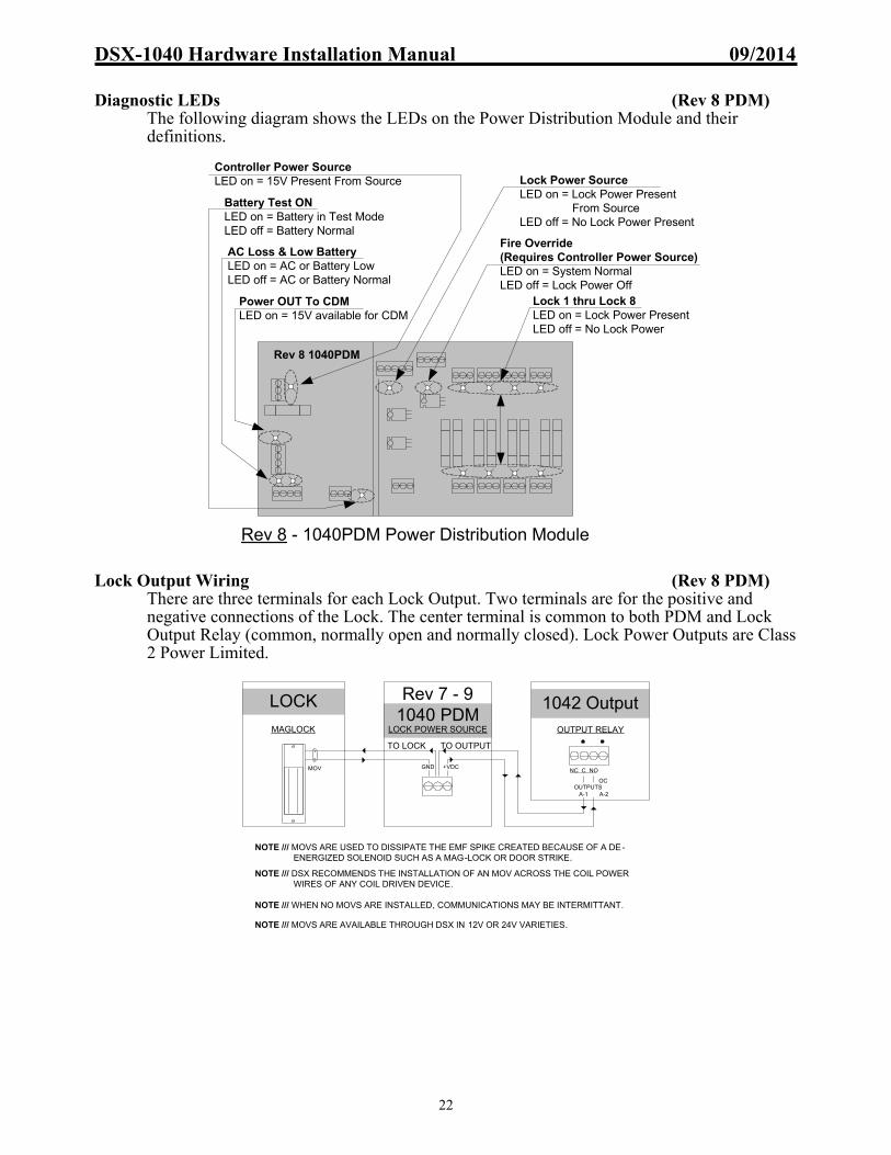
DSX-1040 Hardware Installation Manual 09/2014
22
Diagnostic LEDs (Rev 8 PDM)
The following diagram shows the LEDs on the Power Distribution Module and their definitions.
Lock Output Wiring (Rev 8 PDM)
There are three terminals for each Lock Output. Two terminals are for the positive and negative connections of the Lock. The center terminal is common to both PDM and Lock Output Relay (common, normally open and normally closed). Lock Power Outputs are Class 2 Power Limited.
Rev 8 - 1040PDM Power Distribution Module
Controller Power SourceLED on = 15V Present From Source
AC Loss & Low BatteryLED on = AC or Battery LowLED off = AC or Battery Normal
Battery Test ONLED on = Battery in Test ModeLED off = Battery Normal
Lock 1 thru Lock 8LED on = Lock Power PresentLED off = No Lock Power
Fire Override (Requires Controller Power Source)LED on = System NormalLED off = Lock Power Off
Rev 8 1040PDM
Power OUT To CDMLED on = 15V available for CDM
Lock Power SourceLED on = Lock Power Present From SourceLED off = No Lock Power Present
NOTE /// MOVS ARE USED TO DISSIPATE THE EMF SPIKE CREATED BECAUSE OF A DE- ENERGIZED SOLENOID SUCH AS A MAG-LOCK OR DOOR STRIKE.
NOTE /// MOVS ARE AVAILABLE THROUGH DSX IN 12V OR 24V VARIETIES.
NOTE /// DSX RECOMMENDS THE INSTALLATION OF AN MOV ACROSS THE COIL POWER WIRES OF ANY COIL DRIVEN DEVICE.
NOTE /// WHEN NO MOVS ARE INSTALLED, COMMUNICATIONS MAY BE INTERMITTANT.
Rev 7 - 9 1040 PDM
1042 OutputLOCK POWER SOURCE
TO LOCK TO OUTPUT
+VDCMOV
MAGLOCK
LOCK
OUTPUT RELAY
GNDNC C NO
OUTPUTS A-1 A-2
OC

DSX-1040 Hardware Installation Manual 09/2014
23
Note /// Notice Revision of PDM (Shown is Revision 7) Power Connections from Power Supplies to DSX-1040PDM (Rev 7 PDM)
Lock power is connected from the Lock Power Supply to terminals 27 for positive and 28 for negative. Lock Power Outputs are Class 2 Power Limited.
Controller power is connected from the Controller Power Supply to terminals 1 for positive and 2 for negative. Terminals 3 and 4 provide power to the DSX-1040CDM which redistributes it to each controller.
Battery Connections on the DSX-PDM
DSX recommends for Controller Power a minimum of 2 - 12V 7AH batteries in parallel on terminals 9 and 10 of the PDM. Terminal 9 is battery positive and terminal 10 is battery negative.
For Lock Power – Battery backup is optional for Lock power.
For 12V Locks Connect 2 – 12V 7AH Batteries in parallel to terminal 9 and 10. For 24V Locks Connect 2 – 12V 7AH Batteries in series using the Splice terminal 13 to connect the two batteries together. Terminal 12 is positive and 14 is negative.
Battery Voltage Selection for Lock Power
The Lock Power Battery Charging Circuit voltage is selected by this jumper located in the center of the board. Set the jumper on the upper two pins to charge the12Volt batteries in parallel and on the lower two pins to charge 24Volts worth of backup batteries that are connected together in series.
Battery Test Input
When a negative is placed on the “Battery Test Input” (terminal 11) the PDM will shut off the charging circuit to the controller power batteries and place a load on the batteries for 1 minute. If the batteries drop below approximately 10volts the low battery output is activated. The test lasts for one minute and will not restart until the negative or ground is removed from the test input and then reapplied. The Input can be connected to one of the unused open collector outputs on one of the controllers or switched to ground through an unused relay output. Program the output with a time zone that turns on for one minute per day.
Battery Requirements
All DSX 1040 Controller Packages must have two Back-up Batteries. The Batteries must be a Powersonic PS-1270, an Interstate PC-1270, or an SBS S-1272. Other batteries may draw too much current on initial recharge.
PANEL POWER
Main 15V infrom AS-150
1040PDM Rev.7DSX Access Systems
+15V8AIN
GND
+12V8A
OUTGND
DO
NO
T C
OM
MO
N G
RO
UN
D B
ET
WE
EN
PA
NE
L A
ND
LO
CK
PO
WE
R1
23
4
OUT TO CDM
12
V O
UT
FU
SE
LOAD SHED
NORMAL
LOAD SHED BYPASSED
BATTERYTESTON
AC LOSS5 6 7 8
LOW BATTERYN.C. CONTACTS
BATTERY+9 10 11
GND BATTERY
12V BATTERY BACKUP FOR PANEL POWERTEST INPUT
DO
NO
T U
SE
IF P
RO
HIB
ITE
D
BY
LO
CA
L C
OD
E
12 13 14
RE
PL
AC
E F
US
ES
WIT
H S
AM
E T
YP
E A
ND
RA
TIN
G
BATTERY+ BATTERY-
SPLICE POINT FOR 24V BATTERY HOOKUP
BATTERY BACKUPFOR LOCK POWER (optional)
BATTERY VOLTAGE SELECT
12V
24V
FIRE OVERRIDE
31 3432 33
LOCK POWER
Dry Contactsfrom FirePanel:
To next PDMor to Inputfor alarmindicationShort = Normal
Open = Override
Fire OverrideNormal
27 3028 29
MAIN INPUTFrom AS-150(15/27VDC)
+VDC GND
Lock AC LossOutputN.C.Contacts
24 25 26+VDC GND
PANEL LOCKLOCK 8
TO TO
21 22 23+VDC GND
PANEL LOCKLOCK 7
TO TO
18 19 20+VDC GND
PANEL LOCKLOCK 6
TO TO
15 16 17+VDC GND
PANEL LOCKLOCK 5
TO TO
+VDCGND
PANELLOCK
LOCK 4TOTO
44 45 46+VDCGND
PANELLOCK
LOCK 3TOTO
41 42 43+VDCGND
PANELLOCK
LOCK 2TOTO
38 39 40+VDCGND
PANELLOCK
LOCK 1TOTO
35 36 37
8A
3AG
250
V
Power IN OK
Power OUT OK
Lock PowerON
LO
CK
1
LO
CK
5
1A
3AG
250
V
1A
3AG
250
V
LO
CK
2
LO
CK
6
1A
3AG
250
V
1A
3AG
250
V
LO
CK
3
LO
CK
7
1A
3AG
250
V
1A
3AG
250
V
LO
CK
4
LO
CK
8
1A
3AG
250
V
1A
3AG
250
V
Power ON Power ON Power ON Power ON
Power ONPower ONPower ONPower ON

DSX-1040 Hardware Installation Manual 09/2014
24
Fire Override Input (Rev 7 PDM)
The Lock Override Input must see a closure on terminals 31 & 32 for power to be passed on to each of the individually fused lock output. This closure can be from a Fire System Relay or other signal device that can provide a contact closure rated high enough to carry the maximum current draw of all 8 outputs (locks). When the Input Opens, Lock power is dropped to all 8 outputs simultaneously.
Fire Override Output
The Lock Override Output provides a closure on terminals 33 & 34 until the Lock Override Input faults. When the Lock Override Input faults it causes the Lock Override Output to open. The open of the Lock Override Output can connect to a DSX monitored Input of a 1042, 1044 etc. for monitoring. Optionally it can be connected to another PDM at terminals 31 & 32 to cause a Lock Override Input to fault.
AC Power Loss Output If power from the Controller Power Supply is lost on terminals 1 & 2 the AC Loss LED is illuminated on the PDM and terminals 5 & 6 change states. If power from the Lock Power Supply is lost on terminals 27 & 28 the Lock AC Loss LED is illuminated on the PDM and terminals 29 & 30 change states. These AC Loss contacts are N.C. dry contacts and be connected to an unused input on one of the controllers that can report the condition to the PC.
Low Battery Output
If low battery voltage is detected, an LED is illuminated on the PDM and a relay output, terminals 7 & 8, is energized providing a dry contact open condition. This set of N.C. dry contacts can be connected to an unused input on one of the controllers that can report the condition to the PC.
Fuse Locations and Ratings
The following diagram shows the fuse locations and ratings for all fuses on the Power Distribution Module.
PANEL POWER
Main 15V infrom AS-150
1040PDM Rev.7DSX Access Systems
+15V8AIN
GND
+12V8A
OUTGND
DO
NO
T C
OM
MO
N G
RO
UN
D B
ET
WE
EN
PA
NE
L A
ND
LO
CK
PO
WE
R1
23
4
OUT TO CDM
12V
OU
T F
US
E
LOAD SHED
NORMAL
LOAD SHED BYPASSED
BATTERYTESTON
AC LOSS5 6 7 8
LOW BATTERYN.C. CONTACTS
BATTERY+9 10 11
GND BATTERY
12V BATTERY BACKUP FOR PANEL POWERTEST INPUT
DO
NO
T U
SE
IF P
RO
HIB
ITE
D
BY
LO
CA
L C
OD
E
12 13 14
RE
PLA
CE
FU
SE
S W
ITH
SA
ME
TY
PE
AN
D R
AT
ING
BATTERY+ BATTERY-
SPLICE POINT FOR 24V BATTERY HOOKUP
BATTERY BACKUPFOR LOCK POWER (optional)
BATTERY VOLTAGE SELECT
12V
24V
FIRE OVERRIDE
31 3432 33
LOCK POWER
Dry Contactsfrom FirePanel:
To next PDMor to Inputfor alarmindicationShort = Normal
Open = Override
Fire OverrideNormal
27 3028 29
MAIN INPUTFrom AS-150(15/27VDC)
+VDC GND
Lock AC LossOutputN.C.Contacts
24 25 26+VDC GND
PANEL LOCKLOCK 8
TO TO
21 22 23+VDC GND
PANEL LOCKLOCK 7
TO TO
18 19 20+VDC GND
PANEL LOCKLOCK 6
TO TO
15 16 17+VDC GND
PANEL LOCKLOCK 5
TO TO
+VDCGND
PANELLOCK
LOCK 4TOTO
44 45 46+VDCGND
PANELLOCK
LOCK 3TOTO
41 42 43+VDCGND
PANELLOCK
LOCK 2TOTO
38 39 40+VDCGND
PANELLOCK
LOCK 1TOTO
35 36 378A
3A
G 2
50V
Power IN OK
Power OUT OK
Lock PowerON
LOC
K 1
LOC
K 5
1A 3
AG
250
V
1A 3
AG
250
V
LOC
K 2
LOC
K 6
1A 3
AG
250
V
1A 3
AG
250
V
LOC
K 3
LOC
K 7
1A 3
AG
250
V
1A 3
AG
250
V
LOC
K 4
LOC
K 8
1A 3
AG
250
V
1A 3
AG
250
V
Power ON Power ON Power ON Power ON
Power ONPower ONPower ONPower ON
(Rev 7) 1040PDM Power Distribution Module
F1 thru F8 = 12VDC Power Out / Littlefuse Part #312001 / 250V 1amp
F9 = 12VDC Power Out / Littlefuse Part #312008 / 250V 8amp
Rev 71040PDM

DSX-1040 Hardware Installation Manual 09/2014
25
Diagnostic LEDs (Rev 7 PDM)
The following diagram shows the LEDs on the Power Distribution Module and their
definitions.
Lock Output Wiring (Rev 7 PDM) There are three terminals for each Lock Output. Two terminals are for the positive and negative connections of the Lock. The center terminal is common to both PDM and Lock Output Relay (common and normally open or normally closed). Lock Power Outputs are Class 2 Power Limited.
Power From Lock Power SourceLED on = Lock Power Present From SourceLED off = No Lock Power Present
Rev 7 - 1040PDM Power Distribution Module
Power From Panel Power SourcePower IN = LED on = 15V Present From SourcePower OUT = LED on = 12V Outbound to 1040CDM
AC Loss & Low BatteryLED on = AC or Battery LowLED off = AC or Battery Normal
Battery Test ONLED on = Battery in Test ModeLED off = Battery Normal
Lock 1 thru Lock 8LED on = Lock Power PresentLED off = No Lock Power
Fire OverrideLED on = System NormalLED off = Lock Power Off
Rev 7 1040PDM
NOTE /// MOVS ARE USED TO DISSIPATE THE EMF SPIKE CREATED BECAUSE OF A DE- ENERGIZED SOLENOID SUCH AS A MAG-LOCK OR DOOR STRIKE.
NOTE /// MOVS ARE AVAILABLE THROUGH DSX IN 12V OR 24V VARIETIES.
NOTE /// DSX RECOMMENDS THE INSTALLATION OF AN MOV ACROSS THE COIL POWER WIRES OF ANY COIL DRIVEN DEVICE.
NOTE /// WHEN NO MOVS ARE INSTALLED, COMMUNICATIONS MAY BE INTERMITTANT.
Rev 7 - 9 1040 PDM
1042 OutputLOCK POWER SOURCE
TO LOCK TO OUTPUT
+VDCMOV
MAGLOCK
LOCK
OUTPUT RELAY
GNDNC C NO
OUTPUTS A-1 A-2
OC

DSX-1040 Hardware Installation Manual 09/2014
26
Note /// Notice Revision of PDM (Shown is Revision 6 or Lower) Power Connections from the Power Supplies to DSX-1040PDM (Rev 6 PDM and lower)
Lock power is connected from the Lock Power Supply to terminals 31 for positive and 32 for negative. Lock Power Outputs are Class 2 Power Limited.
Controller power is
connected from the Controller Power Supply to terminals 1 for positive
and 2 for negative. Terminals 3 and 4 provide power to the DSX-1040CDM which redistributes it to each controller.
Battery Connections on the DSX-PDM
DSX recommends for Controller Power a minimum of 2 - 12V 7AH batteries in parallel on terminals 9 and 10 of the PDM. Terminal 9 is battery positive and terminal 10 is battery negative.
For Lock Power – Battery backup is optional for Lock power.
For 12V Locks Connect 2 – 12V 7AH Batteries in parallel to terminal 12 and 14. For 24V Locks Connect 2 – 12V 7AH Batteries in series using the Splice terminal 13 to connect the two batteries together. Terminal 12 is positive and 14 is negative.
Battery Voltage Selection for Lock Power
The Lock Power Battery Charging Circuit voltage is selected by this jumper located in the center of the board. Set the jumper on the upper two pins to charge the12Volt batteries in parallel and on the lower two pins to charge 24Volts worth of backup batteries that are connected together in series.
Battery Test Input
When a negative is placed on the Battery Test Input (terminal 11) the PDM will shut off the charging circuit to the controller power batteries and place a load on the batteries for 1 minute. If the batteries drop below approximately 10volts the low battery output is activated. The test lasts for one minute and will not restart until the negative or ground is removed from the test input and then reapplied. The Input can be connected to one of the unused open collector outputs on one of the controllers or switched to ground through an unused relay output. Program the output with a time zone that turns on for one minute per day.
Battery Requirements
All DSX 1040 Controller Packages must have two Back-up Batteries. The Batteries must be a Powersonic PS-1270, an Interstate PC-1270, or an SBS S-1272. Other batteries may draw too much current on initial recharge.
Rep
lace
Fus
es W
ith S
am
e T
ype
And
Rat
ing
DO
NO
T C
OM
MO
N G
ND
TW
EE
N P
AN
EL
& L
OC
K P
OW
ER
3534
15 / 24VDC
12 13 14
CONTROLLER POWER
12V
OU
T F
US
E
8A
3A
G 2
50V
DC SUPPLYFROM AS-150
12
34
5 6 7 8 9 10 11
POWER IN
POWER OUT
GND
+15V8AIN
GND
+12V8AOUT
AC Loss Low Batt.N.C. Contacts
12V Batt. B/U Controller Power
Battery +
GN
D
Te
st
Batt.BackupFor Lock Power(OPTIONAL)
LockPower ON
Do
No
t Use
if P
rohi
bite
d B
y L
oca
l Co
de
GN
D
Batt.Test ON
1040PDMRev 6 & less
Fire
Ovrride
+
DC Supply
333231+VDC GND
AS-100Lock 1
Lock Relay
GND +VDC36 37 38 39
Lock 2Lock Relay
GND +VDC40 41 42 43
Lock 3Lock Relay
GND +VDC44 45 46 47
Lock 4Lock Relay
GND +VDC48 49 50 51
1A 3
AG
250
V
1A 3
AG
250
V
1A 3
AG
250
V
1A 3
AG
250
V
1A 3
AG
250
V
1A 3
AG
250
V
1A 3
AG
250
V
1A 3
AG
250
V
Lock 5
18171615
LockRelay
GND+VDC
Lock 6
22212019
LockRelay
GND+VDC
Lock 7
26252423
LockRelay
GND+VDC
Lock 8
30292827
LockRelay
GND+VDC
JumperBatteriesLock
12V24V
Splice Point

DSX-1040 Hardware Installation Manual 09/2014
27
Fire Override Input (Rev 6 PDM and lower)
The Lock Override Input must see a closure on terminals 34 & 35 for power to be passed on to each of the individually fused lock outputs. This closure can be from a Fire System Relay or other signal device that can provide a contact closure rated high enough to carry the maximum current draw of all 8 outputs (locks). When the Input opens, Lock power is dropped to all 8 outputs simultaneously.
Note /// The total amount of voltage and current used for locks at this PDM are being controlled through terminals 34 & 35. The device that provides the normally closed contacts that controls the Fire Override must have a rating equal to the required voltage and total current needed by all locks connected to this PDM.
AC Power Loss Output If power from the Controller Power Supply is lost on terminals 1 & 2 of the PDM the AC Lost LED is illuminated on the PDM and a relay output, terminals 5 & 6, is energized providing a dry contact open condition. This set of N.C. contacts can be connected to an unused input on one of the controllers that can report the condition to the PC.
Low Battery Output
If low battery voltage is detected, an LED is illuminated on the PDM and a relay output is energized providing a dry contact open condition on terminals 7 & 8. This set of N.C. contacts can be connected to an unused input on one of the controllers that can report the condition to the PC.
Fuse Locations and Ratings
The following diagram shows the fuse locations and ratings for all fuses on the Power Distribution Module.
R
epla
ce F
uses
With
Sam
e T
ype
And
Rat
ing
DO
NO
T C
OM
MO
N G
ND
TW
EE
N P
AN
EL
& L
OC
K P
OW
ER
3534
15 / 24VDC
12 13 14
CONTROLLER POWER
12V
OU
T F
US
E
8A 3
AG
250
V
DC SUPPLYFROM AS-150
12
34
5 6 7 8 9 10 11
POWER IN
POWER OUT
GND
+15V8AIN
GND
+12V8AOUT
AC Loss Low Batt.N.C. Contacts
12V Batt. B/U Controller Power
Battery +
GN
D
Te
st
Batt.BackupFor Lock Power(OPTIONAL)
LockPower ON
Do
Not
Use
if P
rohi
bite
d B
y Lo
cal C
ode
GN
D
Batt.Test ON
1040PDMRev 6 & less
Fire
Ovrride
+DC Supply
333231+VDC GND
AS-100Lock 1
Lock Relay
GND +VDC36 37 38 39
Lock 2Lock Relay
GND +VDC40 41 42 43
Lock 3Lock Relay
GND +VDC44 45 46 47
Lock 4Lock Relay
GND +VDC48 49 50 51
1A 3
AG
250
V
1A 3
AG
250
V
1A 3
AG
250
V
1A 3
AG
250
V
1A 3
AG
250
V
1A 3
AG
250
V
1A 3
AG
250
V
1A 3
AG
250
V
Lock 5
18171615
LockRelay
GND+VDC
Lock 6
22212019
LockRelay
GND+VDC
Lock 7
26252423
LockRelay
GND+VDC
Lock 8
30292827
LockRelay
GND+VDC
JumperBatteriesLock
12V24V
Splice Point
1040PDM Power Distribution Module
F1 thru F8 = 12VDC Power Out / Littlefuse Part #312001 / 250V 1amp
F9 = 12VDC Power Out / Littlefuse Part #312008 / 250V 8amp
Rev 6 or Less1040PDM

DSX-1040 Hardware Installation Manual 09/2014
28
Diagnostic LEDs (Rev 6 PDM and lower)
The following diagram shows the LEDs on the Power Distribution Module and their definitions.
Lock Output Wiring (Rev 6 PDM and lower) There are four terminals for each Lock Output. Two terminals are for the positive and negative connections of the Lock. Two terminals are for the output relay connections (common and normally open or normally closed). Lock Power Outputs are Class 2 Power Limited.
1040PDM Power Distribution Module
Power From Panel Power SourcePower IN = LED on = 15V Present From SourcePower OUT = LED on = 12V Outbound to 1040CDM
AC Loss & Low BatteryLED on = AC or Battery LowLED off = AC or Battery Normal
Battery Test ONLED on = Battery in Test ModeLED off = Battery Normal
Power From Lock Power SourceLED on = Lock Power Present From SourceLED off = No Lock Power Present
Lock 1 thru Lock 8LED on = Lock Power PresentLED off = No Lock Power
Rev 6 & Less 1040PDM
1042 OutputLOCK POWER SOURCE
TO LOCK TO OUTPUT
GND +VDCMOV
MAGLOCK
LOCK
INTERNAL JUMPER
OUTPUT RELAY
Rev 6 & less 1040 PDM
NC C NO
OUTPUTS A-1 A-2
OC

DSX-1040 Hardware Installation Manual 09/2014
29
DSX-1042 Reader Controller Features
Hardware Feature Quantities Description
Relay Outputs 2 Single Pole Double Throw 5A@30VDC or 30VAC
Open Collector Outputs 2 Fully programmable – 100ma switched negative
Reader/Keypad Ports 2 Supports Wiegand, RS-422, and Clock and Data
Reader/Keypad LED Outputs 6 Open Collector – 100ma
12VDC Output 2 12VDC fused at 1A - Shared to both reader ports
Inputs (Supervised) 8 Accept NO and/or NC with individual Status LEDs
Status LEDs 22 Blown Fuse, Input, Output, Communications, and Processor Status LEDs
PreWarn Outputs 2 Open Collector – 100ma for Door Held Open
Master to PC Communications 1 RS-232 9600Baud 8-1-N
Slave Communications 1 RS-232 9600Baud to 1040CDM – RS-485 from 1040CDM to 1040CDM 4000 feet – 2 twisted pair
Power Input 1 12VDC – from DSX-1040CDM – 1.5A
32 33 34 3524 25 26 27 28 29 313023 40 41 42
SIDE B INPUTS
INP5INP6
INP7INP8
COMM
SIDE B READER PORTPREWARN-100mA
LED1LED2
LED3D0
D1GND
+12VDC1A MAX
39
OUTPUT B-2
+12VDCINPUT
GND
1A 3AG 250V
12V
Fu
se LED
9
OUTPUT A-2
10 11 12 13 14 15 16 17
PREWARN-100mA
LED1LED2
LED3D0
D1GND
+12VDC1A MAXSIDE A READER PORT
18 19 20 21 22
SIDE A INPUTS
INP5INP6
INP7INP8
COMM1 3 42
TX RXSLAVE
TX RXMASTER
GND
5 36 37 38NC C NO
OUTPUT B-1
6 7 8NC C NO
OUTPUT A-1
DS
X-1
042
2 D
oor
Con
tro
ller
1TX-RX
COMM (RS-232)
TX-RX
GN
D
DSX-1042 ControllerDSX Access Systems, Inc.
(800)346-5288
2
Slave
3 4
Master SIDE A INPUTS
18 19 20 21 22I-5 I-6 I-7 I-8 common
SIDE B INPUTS
23 24 25 26 27I-5 I-6 I-7 I-8 common
10 11 12 13 14 15 16 17LED
1D0 D1 GND +12VDC
1A
SIDE A READER PORT
Pre-warn
LED2
LED3
28 29 30 31 32 33 34 35
LED1
D0 D1 GND +12VDC1A
SIDE A READER PORT
Pre-warn
LED2
LED3
9
SIDE A OUTPUTSOP2OP1
6 7 8NC C NO
39
SIDE B OUTPUTSOP2OP1
36 37 38NC C NO
POWER40 41 42
+12VDC IN
GND
Reader Ports:-Pre-warn: Open-collector, sinks 100mA. Pulses @ 1/3"Door Held Open" time. On steady when I-7 is in alarm.-LED1: - 100mA when Output 1 "secure".-LED2: - 100mA when Output 1 "open".-LED3: - 100mA pulse on access denied/keypad entry.-D0: Reader DATA 0 or Clock signal.-D1: Reader DATA 1 or Data signal.-+12VDC Output: 1A max combined from both sides.
Addressing Examples:-Master Loc. 1: 1 & 8 ON-Master Loc. 2: 2 & 8 ON-Master Loc. 3: 1,2 & 8 ON*(On a master set Loc.# & 8)-Slave Dev. 2 & 3: 2 ON-Slave Dev. 4 & 5: 3 ON-Slave Dev. 6 & 7: 2 & 3 ON*(On a slave set even dev#)
Inputs:-Can be wired for 2, 3 or 4 state monitoring.-Can use N.O. or N.C. contacts-Use 1k Ohm resistor in series(N.C.) or parallel (N.O.)-Input 7 is Door Contact-Input 8 is Exit Request
Outputs:1: SPDT Relay rated 5A@30VDC or 30VAC2: Open-Collector, can sink 100mA at 12VDC * Cut MOV's V1-V4 if switching > 50v*
12v Output Fuse. LED ON indicates blown fuse.Replace only with same type:
1A, 250V, 3AG
12VDC Input power from powersupply. Allow 2A per 1042 board
Panel Status LED'sPower ONPollingBufferDownloadHeartbeat
Switch# Value(binary)1 1 (master only)2 23 44 85 166 327 648 Master/Slave Mode
*Please refer to the DSX Hardware Installation Manual for installation details.
5
O.C. O.C.

DSX-1040 Hardware Installation Manual 09/2014
30
DSX-1042 Typical Field Connections
9 10 12 23 24 25 2613 16 17 18 19 20 21 225 6 7 271 2TX RX
SLAVES
3 4RX
8 11 14 15
MASTERTX
INTERNAL COMM
TX+ RX+TX- RX-A B C D A B C D
1048 TO 1048 COMM-WIRE OUT TO IN, TX TO RX or A-A, B-B, C-C, D-D
RX+ TX+RX- TX-
485 IN 485 OUT
+12V8A
GN
D
POWER IN
+5V.5A
GN
D
+12V1.5A
GN
D
SECONDARY OUT POWER OUTPUT, 12V 1.5A TO EACH
+12V
+12V
+12V
+12V
GN
D
GN
D
GN
D
GN
D
GN
D
12V
Fuse
1.5
A 2
50V
3AG
F1
F2
F3
F4
F5
F6
12V
Fuse
1.5
A 2
50V
3AG
12V
Fuse
1.5
A 2
50V
3AG
12V
Fuse
1.5
A 2
50V
3AG
12V
Fuse
1.5
A 2
50V
3AG
5V
Fu
se .5A
250
V 3
AG
LE
D o
ff indica
tes blo
wn
fuse
RE
PL
AC
E F
US
ES
WIT
H T
HE
SA
ME
TY
PE
AN
D V
AL
UE
SET J1 & J2 AS "MAS" MASTER IF THERE IS A MASTER CONTROLLER IN THIS 1048.
SET J1 & J2 AS "SLAVE" IF THERE IS NOT A MASTER
CONTROLLER IN THIS 1048.
INTERNAL TO 1048 EXTERNAL TO 1048J1J2
SLAVE MAS
1040CDM
COMMUNICATION COMMUNICATION
MOV
BL
AC
K
RE
D
WH
ITE
GR
EE
N
BR
OW
N
SH
IEL
D
NCNO
DPDT EXIT BUTTON
1K OHM E.O.L.
1K
OH
M E
.O.L
.
1K
OH
M E
.O.L
.
TO +V OF 1048
SIDE B
1K OHM E.O.L.
DOOR CONTACTS
MAGLOCK
PANEL TAMPER
FROM 1040PDM
FROM 1040PDM
TO 1040PDM
TO 1040PDM
100maDEVICE
TO
RX
TE
RM
OF
ALL
SL
AV
E C
ON
TR
OLL
ER
S IN
TH
IS 1
048
TO
5V
DC
NE
ED
S
TO 1042 12VDC POWER INPUTS
TO
TX
TE
RM
OF
ALL
SL
AV
E C
ON
TR
OL
LE
RS
IN T
HIS
104
8
TO MASTER 1042 RX TERM
TO MASTER 1042 TX TERM
BL
AC
K
RE
D
WH
ITE
GR
EE
N
BR
OW
N
OR
AN
GE SH
IEL
DNC NO
FROM 1040PDM
MOV
1K
OH
M E
.O.L
.1
K O
HM
E
.O.L.
1K OHM E.O.L.
1K OHM E.O.L.
SIDE A
DOOR CONTACTS
DPDT EXIT BUTTON
MAGLOCK
PRE-WARNSOUNDER
SERVER
RS-232 PORT
FROM 1040PDM
TO 1040PDM
TO 1040PDM
SEE "CONTROLLER TO CONTROLLER" COMM CHARTS FOR 485IN AND 485OUT
WIRING SPECIFICS
DS-12KEYPAD
HID PROX
TO
12
VD
C N
EE
DS
TO 1040CDM
TO 1040CDM TO +VOF 1048 FROM COMM
SEE CHARTS OF THIS PAGE
12345678
POWER
POLL
BUFFER
DOWNLOAD
ALIVE
12V
FU
SE
LE
D
Replace with same type 1A 3AG 250V12V OUTPUT FUSE 36 37 38
NC NOCOM
SERIAL #
MOV USAGE:MOV'S MUST BE INSTALLED AT ALL COILS, ACROSS THE POWER INPUT.VOLTAGES HIGHER THAN 30 V. SHOULD NOT BE SWITCHED THROUGH THE OUTPUT RELAYS
DSX-1042Intelligent Controller
I.E. LOCATION 1 MASTER CONTROLLER SW 1 & 8 ON, ON = BLACK ON = DOWN
6 7 8
NC NOCOM
+1
2V
INP
UT
24 25 26 2723
GND
32 33 34 3528 29 3130 40 41 42
SIDE B INPUTS
INP5INP6
INP7INP8
COM PWLED1
D0+12V1A*
LED2LED3 D1
GND
SIDE B READER
36 37 38 39
OUTPUTS
OC10 11 12 13 14 15 16 17 18 19 20 21 221 2
TX RXSLAVE
PWLED1
D0+12V1A* SIDE A INPUTS
3 4TX RX
MASTER
6 7 8 9
OUTPUTS
LED2LED3 D1
GND
SIDE A READER
INP5INP6
INP7INP8
COMOC5
GND A-1 A-2 B-1 B-2
OUTPUT A1 & B1 = FORM-C,DRY RATED AT 5A,30V
Both Side A and Side B
Output Relays are
ShownDe-energized
"PW" TERMINALS 10&28= PREWARN OUTPUTS, OPEN COLLECTOR, SINKS 100mA
OUTPUT A2 & B2 = OPEN COLLECTOR, SINKS 100mA"OC" TERMINALS 9&39
*READER 12VDC = 1 AMP SHARED BETWEEN 17&35
104
2
2 D
OO
R C
ON
TR
OLL
ER
4 CONDUCTORS FROM “POWER OUT” OF 1040 PDM
TO PDM TERM 4
TO PDM TERM 5
TO PDM TERM 6
TO PDM TERM 7
1048 W/ MASTER TO SLAVE
RS-485"IN" TO RS-485"IN"TX to RX RX to TX
1048 W/ SLAVE TO SLAVE
RS-485"OUT" TO RS-485"IN"RX to TX TX to RX
POLARITY
ALWAYS + TO + AND - TO -
1040CDM TO 1040CDM RS-485 COMMUNICATIONS
MOV Usage: If voltages higher than 50 volts are to be switched through the Output relay contact, the individual MOV's (V1&V2, V3&V4) should be removed from the specific Output .
V1 V2 V3 V4
Output Extenders: Use the DSX-OX4 to provide 4 additional Form-C Output Relays or the DSX-1043 to provide up to 16 Form-C Output Relays without using additional Device Addresses . One Extender can connect to a DSX-1022 or DSX-1042 at the Master port of a SLAVE CONTROLLER. (Required Terminations include TX-RX, RX-TX & +12VDC & GND).
ORDSX-LAN (RS-232 PORT)TO GND OF
TO TX OF TO RX OF
DSX-MCI (RS-232 PORT) DSX-MODEM (RS-232 PORT)DSX-USB (RS-232 PORT)
DB9 SERIAL PORT PIN #5DB9 SERIAL PORT PIN #3DB9 SERIAL PORT PIN #2
3 4 5TX RX GND

DSX-1040 Hardware Installation Manual 09/2014
31
DSX-1042 Power and Communications
MCI
TO
12V
DC
NE
ED
S
TO 1042 12VDCPOWER INPUTS
TO
5VD
C N
EE
DS
FROM MASTER TX
FROM MASTER RX
TO NEXT SLAVEIN THIS 1048
OUTPUT A2 IS AN OPEN COLLECTOR OUTPUT. USED HERE TO ACTIVATE THE BATTERY TEST BY TZEXAMPLE 1000-1001
1040E
TO 1040CDM
+12
VIN
PU
T
9 10 12 23 24 25 2613 16 17 18 19 20 21 225 6 7 271 2TX RX
SLAVES
3 4RX
8 11 14 15
MASTERTX
INTERNAL COMM
TX+ RX+TX- RX-A B C D A B C D
1048 TO 1048 COMM - WIRE OUT TO IN, TX TO RX or A-A, B-B, C-C, D-D
RX+ TX+RX- TX-
485 IN 485 OUT
+12V8A
GN
D
POWER IN
+5V.5A
GN
D
+12V1.5A
GN
D
SECONDARY OUT POWER OUTPUT, 12V 1.5A TO EACH
+12V
+12V
+12V
+12V
GN
D
GN
D
GN
D
GN
D
GN
D
DSX-1040CDMJ1J2
SET J1 & J2 AS"MAS" MASTER IF THERE IS A MASTER CONTROLLER IN THIS 1048.
SET J1 & J2 AS "SLAVE" IF THERE IS NOT A MASTER CONTROLLER IN THIS 1048.
SLAVE MAS
SEE "CONTROLLER TO CONTROLLER" COMM
CHARTS FOR 485IN AND 485OUT WIRING SPECIFICS
12
V F
US
E LE
D
Replace with same type 1A 3AG 250V12V OUTPUT FUSEDSX-1042Master
+1
2VIN
PU
T
24 25 26 2723
GND
32 33 34 3528 29 3130 40 41 42
SIDE B INPUTS
INP5INP6
INP7INP8
COM PWLED1
D0+12V
1A
LED2LED3 D1
GND
SIDE B READER
36 37 38 39
OUTPUTS
OC10 11 12 13 14 15 16 17 18 19 20 21 221 2
TX RXSLAVE
PWLED1
D0+12V
1A SIDE A INPUTS
3 4TX RX
MASTER
6 7 8 9
OUTPUTS
LED2LED3 D1
GND
SIDE A READER
INP5INP6
INP7INP8
COMOC5
GND A-1 A-2 B-1 B-2
12V
FU
SE
LE
D
Replace with same type 1A 3AG 250V12V OUTPUT FUSEDSX-1042Slave
+12
VIN
PU
T
24 25 26 2723
GND
32 33 34 3528 29 3130 40 41 42
SIDE B INPUTS
INP5INP6
INP7INP8
COM PWLED1
D0+12V
1A
LED2LED3 D1
GND
SIDE B READER
36 37 38 39
OUTPUTS
OC10 11 12 13 14 15 16 17 18 19 20 21 221 2
TX RXSLAVE
PWLED1
D0+12V
1A SIDE A INPUTS
3 4TX RX
MASTER
6 7 8 9
OUTPUTS
LED2LED3 D1
GND
SIDE A READER
INP5INP6
INP7INP8
COMOC5
GND A-1 A-2 B-1 B-2
TX RXSLAVE
FROM N.C. INPUT OF PDM TO MONITOR AC POWER LOSS OF SOURCE FOR LOCKS
TO SLAVE RX
TO SLAVE TX
TO OUTPUT EXTENDER
1040PE
1
2
3
8 9 10 11 12 13 1415 16 17
18 19 20 21 22 23 24 25 26 27 28 29
39 40 41 42 43 44 45 46 47 48 49 50
35 36 37 3830 31 32 33
24V12V
LOADSHED
ACTIVE LOADSHEDINACTIVE
BATTTEST
ON
BATT. V.
BATTERY +
BATTERY - BATTTEST
BACKUP FOR PANELSBACKUP FOR LOCKS
BATT +
SPLICE POINT FOR
BATTERY -AC LOSS
LOW BATTERYTO INPUTS
+15V
GND
PANEL INPUT
+12V
12V OUT FUSE8A 3AG 250V
LOCKINPUT
+ -
AC LOSS
POWER IN OK
POWER OUT OK
LOCK POWERON
FIREOVERRIDE
LOCK 5 LOCK 6 LOCK 7 LOCK 8
LOCK 1 LOCK 2 LOCK 3 LOCK 4
TOLOCK
TOPANEL
TOLOCK
TOPANEL
TOLOCK
TOPANEL
TOLOCK
TOPANEL
24V BATTERY HOOKUP
(Rev 9) DSX-1040PDM
GND
TOCDM
5
4
6
7
GND4A
+12V4A
GND
34
GN
D
TO 1040CDM
PANEL POWER SOURCE
LOCK POWER SOURCE
1k EO
L
1k E
OLBATTERY TEST INITIATOR /
GROUND TO ACTIVATE TEST
1k E
OL
SUPPLY N.C. DRY CONTACTS FROM FIRE PANELSHORT = NORMAL , OPEN = OVERRIDE
TO NEXT PDM OR TO INPUTFOR ALARM INDICATION
TO B/U
BATTERY(S)
TO B/U
BATTERY(S) TOLOCK
TOOUTPUT
RELAY
TO MONITOR AC POWER LOSS OF POWER FOR PANELS
TO MONITOR FOR LOW BATTERY POWER FOR PANELS
N.C. CONTACTS
TO INPUT OF PANEL / N.C.CONTACTS
LOCK POWER SUPPLY IS ORDERED SEPARATELY
AND IS NOT INCLUDED IN THE PKG PARTS LIST
TO 1040CDM
TO 1040PDM LOW BATTERY OUTPUT
TO 1040PDM AC LOSS OUTPUT
TOLOCK
TOOUTPUT RELAY
115V/60HZ or 240V/50HZ AC
115V/60HZ or 240V/50HZ AC
RS-485UP TO 4K FT TX+ to RX+,TX- to RX-,RX+ to TX+,RX- to TX-
15V OR 27V OUT
15V OUT
SEE "POWER SUPPLIES" SECTION FOR POWER SOURCE CONNECTION
SPECIFICS
1 2 3 4
5 6 7 8
1 3
2 4
5 7
6 8
BYPASSEDNORMAL
LOCK1 - LOCK8FIRE OVERRIDE MODE
RS-232 UP TO 50 FT
4 CONDUCTORS REQUIRED
4 CONDUCTORS REQUIRED FROM PDM
DSX-USB
RS
-23
2
RS
-48
5
Su
pplied
Ca
ble
To
PC
U
SB
Po
rt
GND+12V
TX+TX-RX+
RX-
TX
+T
X-
RX
+R
X-
TX
RX
GN
D+
12v
MCI REQUIRED FOR LONG DISTANCES ONLY
OR
DSX-LAN (RS-232 PORT)TO GND OF
TO TX OF
TO RX OF
DSX-MCI (RS-232 PORT)
DSX-MODEM (RS-232 PORT)
DSX-USB (RS-232 PORT)
DB9 SERIAL PORT PIN #5
DB9 SERIAL PORT PIN #3
DB9 SERIAL PORT PIN #2

DSX-1040 Hardware Installation Manual 09/2014
32
DSX-1042 Fuse Rating and Location
Note /// Blown fuse indicators on Controller light only when the fuse is blown and there is a load present. DSX-1042 Diagnostic LEDs
1042 Intelligent Controller
F1 = 12VDC Out / Littlefuse Part #312001 / 250V 1Amp
1042 Intelligent Controller
Inputs A5-A8 & B5-B8LED On when NormalLED Off when Abnormal
Outputs A1-A2 & B1-B2LED On when EnergizedLED Off when De-energized
12V Output Fuse LEDLED On 12v Fuse BlownLED Off 12v Fuse Normal
Communications LED's LED Flashing = Receiving or Transmitting to PC or CDM LED Off when Not Communicating
Power ON = Power OKPolling = CommunicatingBuffer = Full BufferDownload = DownloadingHeartbeat = Alive
Panel Status LED's

DSX-1040 Hardware Installation Manual 09/2014
33
DSX-1042 Overview
The DSX-1042 Controller has 2 reader ports, 2 Form-C relay outputs, 2 digital/open collector outputs and 8 supervised inputs. The panel reader ports support most card formats through a programmable Device Type. By default Input 7 (door position switch), 8 (request to exit) and Output 1 (to control door lock voltage) are linked together to monitor and control a reader controlled door.
Reader Port The 2 reader port power connections are fused at 1 amp collectively. Data 0 and Data 1 connections provide the information from the card read. There are 3 LED connections for Door Status and can indicate door secure, door open and access denied.
Relay Outputs The available Relay Outputs of the DSX-1042 include A1 and B1. These outputs are Form-C relays rated at 5 amps @ 30VDC or 30VAC and commonly used to control lock voltage. DSX Form-C relays provide connectivity from the Normally Closed and Common connections while the relay is not energized and no connectivity from the Normally Open and Common connections when the relay is not energized. When the relay is energized the contacts reverse.
Digital/Open Collector Outputs The available Digital/Open Collector Outputs include A2 and B2. These outputs are used to sink up to 100ma of current and can be used to energize a relay coil or other item that requires 100ma or less.
Inputs The available inputs of a DSX-1042 include A5 thru A8 and B5 thru B8. By default Input 7 and 8 are linked together to monitor a controlled door. These inputs are commonly used to monitor Door Contacts and Exit Button. In the Device Parameters “Use Input 7 and 8” can be set to No for inputs 7 & 8 to operate independently. The 1042 also provides Inputs 5 & 6 that can be used to supervise additional monitored points.
Device Types DSX includes in excess of 250 Device Types (aka card formats). Using Controller Firmware 3098 and higher Device Types of different bit lengths can be used in the same system.

DSX-1040 Hardware Installation Manual 09/2014
34
DSX-1043 / 16 Relay Output Controller Features
Hardware Feature Quantities Description
Relay Outputs 16 Single Pole Double Throw 5A@30VDC or 30VAC
Inputs (Monitored) 2 Accept NC switches w/status LEDs address as A:1 and B:1
Status LEDs 28 Input, Output, Communications, and Processor Status LEDs
Relay Override 1 Accepts NC switch. When opened will de-energize all 16 Outputs.
Master to PC Communications 1 RS-232 9600Baud 8-1-N
Slave Communications 1 RS-232 9600Baud to 1040CDM – RS-485 from 1040CDM to 1040CDM 4000 feet – 2 twisted pair
Power Input 1 12VDC – from DSX-1040CDM – 1.5A
DSX-1043 Controller
Addressing Examples:-Master Loc. 1: 1 & 8 ON-Master Loc. 2: 2 & 8 ON-Master Loc. 3: 1 & 2 & 8 ON*(On a master set Loc.# & 8)-Slave Dev. 2 & 3: 2 ON-Slave Dev. 4 & 5: 3 ON-Slave Dev. 6 & 7: 2 & 3 ON*(On a slave set even dev#)
Switch# Value(binary)1 1 (master only)2 23 44 85 166 327 648 Master/Slave Mode
*Please refer to the DSX Hardware Installation Manual for installation details.
DSX Access Systems, Inc.(800)346-5288
Inputs A:1 & B:1 arenon-supervised,normally closed Inputs(short=normal,open=abnormal
The Relay Override is anormally closed circuit.A short here enablesrelay operation. An openhere forces the relays tothe de-energised state.
12VDC Input pwerfrom 1040CDM
Output Ratings:SPDT Relay rated 5A @30VDC or 30VAC
Panel Status LED's
PollingBuffer
DownloadHeartbeat
NC C NO26 2827OUTPUT B:1
NC C NO28 3130OUTPUT B:2
NC C NO32 3433OUTPUT B:3
NC C NO35 3736OUTPUT B:4
NC C NO56 5857OUTPUT B:7
NC C NO53 5554OUTPUT B:6
NC C NO50 5251OUTPUT B:5
NC C NO1 32OUTPUT A:1
NC C NO4 65OUTPUT A:2
NC C NO44 4645OUTPUT A:7
NC C NO41 4342OUTPUT A:6
NC C NO47 4948OUTPUT A:8
NC C NO10 1211OUTPUT A:4
NC C NO7 98OUTPUT A:3
B:1A:1 COM18 19 20
INPUTSNC C NO38 4039OUTPUT A:5
NC C NO59 6160OUTPUT B:8
Override
POWER
DC IN+12V
GND
21 22 23Relay
24 25
TX RX TX RX GND
COMM (RS-232)
13 15 1614 17SLAVE PC - MASTER
ON OFF
13 15 1614TX RXSLAVE
TX RXMASTER
GND17
38 4039NC C NO
OUTPUT A:5
41 4342NC C NO
OUTPUT A:6
44 4645NC C NO
OUTPUT A:7
47 4948NC C NO
OUTPUT A:8
50 5251NC C NO
OUTPUT B:5
53 5554NC C NO
OUTPUT B:6
56 5857NC C NO
OUTPUT B:7
59 6160NC C NO
OUTPUT B:8
26 2827NC C NO
OUTPUT B:1
29 3130NC C NO
OUTPUT B:2
32 3433NC C NO
OUTPUT B:3
35 3736NC C NO
OUTPUT B:4
1 32NC C NO
OUTPUT A:1
4 65NC C NO
OUTPUT A:2
7 98NC C NO
OUTPUT A:3
10 1211NC C NO
OUTPUT A:4
POLL
BUFFER
DOWNLOAD
ALIVE
21 22 23 24 25
OverrideGND
+12VDC
POWER
INP
UT
A:1
INP
UT
B:1
18 19 20 DS
X-1
043
16
OU
TP
UT
BO
AR
D
ON OFF
1248163264M/S
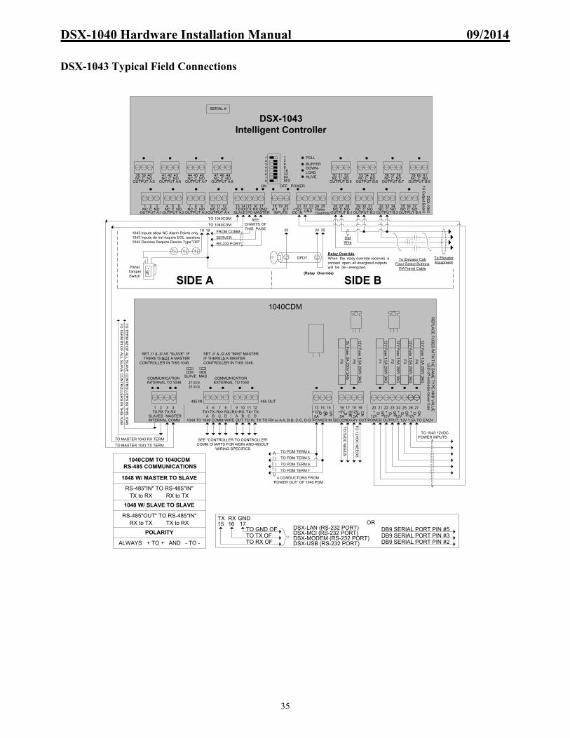
DSX-1040 Hardware Installation Manual 09/2014
35
DSX-1043 Typical Field Connections
TO
TE
RM
#2 O
F A
LL
SL
AV
E C
ON
TR
OLL
ER
S IN
TH
IS 1
04
8
TO
TE
RM
#1 O
F A
LL
SL
AV
E C
ON
TR
OLL
ER
S IN
TH
IS 1
04
8
SIDE BSIDE A
TO 1040CDM
TO 1040CDM
FROM COMM
SERVER
RS-232 PORT
SEE CHARTS OF THIS PAGE
To Elevator Equipment
Hot Wire
To Elevator Cab Floor Select Buttons
VIATravel Cable
191043 Inputs allow NC Alarm Points only.1043 Inputs do not require EOL resistors.1043 Devices Require Device Type "OR"
18 20 24 25
(Relay Override)
Relay OverrideWhen the relay override receives a contact open, all energized outputs will be de - energized.Panel
TamperSwitch
12345678
DSX-1043Intelligent Controller
OUTPUT A:5NC C NO38 4039
OUTPUT A:6NC C NO41 4342
OUTPUT A:7NC C NO44 4645
OUTPUT A:8NC C NO47 4948
OUTPUT A:1NC C NO1 32
OUTPUT A:2NC C NO4 65
OUTPUT A:3NC C NO7 98
OUTPUT A:4NC C NO10 1211
OUTPUT B:1NC C NO26 2827
OUTPUT B:2NC C NO29 3130
OUTPUT B:3NC C NO32 3433
OUTPUT B:4NC C NO35 3736
OUTPUT B:8NC C NO59 6160
OUTPUT B:7NC C NO56 5857
OUTPUT B:6NC C NO53 5554
TX RX TX RX GND13 15 1614 17
SLAVE PC-MASTER
OUTPUT B:5NC C NO50 5251
DC IN+12V GND
21 22 23 24 25Relay OverrideINPUTS
A:1 B:118 2019
ON OFF
1248163264M/S
DS
X-1
043
16 O
utp
ut B
oard
POWER
POLL
BUFFERDOWN-LOADALIVE
DPDT
SERIAL #
9 10 12 23 24 25 2613 16 17 18 19 20 21 225 6 7 271 2TX RX
SLAVES
3 4RX
8 11 14 15
MASTERTX
INTERNAL COMM
TX+ RX+TX- RX-A B C D A B C D
1048 TO 1048 COMM-WIRE OUT TO IN, TX TO RX or A-A, B-B, C-C, D-D
RX+ TX+RX- TX-
485 IN 485 OUT
+12V8A
GND
POWER IN
+5V.5A
GND +12V
1.5A
GND
SECONDARY OUT POWER OUTPUT, 12V 1.5A TO EACH
+12V
+12V
+12V
+12V
GND GND GND GNDGND
12V
Fu
se 1.5
A 2
50V
3AG
F1
F2
F3
F4
F5
F6
12V
Fu
se 1.5
A 2
50V
3AG
12V
Fu
se 1.5
A 2
50V
3AG
12V
Fu
se 1.5
A 2
50V
3AG
12V
Fu
se 1.5
A 2
50V
3AG
5V F
use .5
A 2
50
V 3
AG
LE
D o
ff indica
tes blo
wn
fuseR
EP
LA
CE
FU
SE
S W
ITH
TH
E S
AM
E T
YP
E A
ND
VA
LU
E
SET J1 & J2 AS "MAS" MASTER IF THERE IS A MASTER CONTROLLER IN THIS 1048.
SET J1 & J2 AS "SLAVE" IF THERE IS NOT A MASTER
CONTROLLER IN THIS 1048.
INTERNAL TO 1048 EXTERNAL TO 1048J1J2
SLAVE MAS
1040CDM
COMMUNICATION COMMUNICATION
TO
5V
DC
NE
ED
S
TO 1043 12VDC POWER INPUTSTO MASTER 1043 RX TERM
TO MASTER 1043 TX TERM
SEE "CONTROLLER TO CONTROLLER" COMM CHARTS FOR 485IN AND 485OUT
WIRING SPECIFICS
TO
12
VD
C N
EE
DS
4 CONDUCTORS FROM “POWER OUT” OF 1040 PDM
TO PDM TERM 4
TO PDM TERM 5
TO PDM TERM 6
TO PDM TERM 7
1048 W/ MASTER TO SLAVE
RS-485"IN" TO RS-485"IN"TX to RX RX to TX
1048 W/ SLAVE TO SLAVE
RS-485"OUT" TO RS-485"IN"RX to TX TX to RX
POLARITY
ALWAYS + TO + AND - TO -
1040CDM TO 1040CDM RS-485 COMMUNICATIONS
ORDSX-LAN (RS-232 PORT)TO GND OF
TO TX OF TO RX OF
DSX-MCI (RS-232 PORT) DSX-MODEM (RS-232 PORT)DSX-USB (RS-232 PORT)
DB9 SERIAL PORT PIN #5DB9 SERIAL PORT PIN #3DB9 SERIAL PORT PIN #2
15 16 17TX RX GND

DSX-1040 Hardware Installation Manual 09/2014
36
DSX-1043 Power and Communications
FR
OM
10
40
PD
M
TO
12V
DC
NE
ED
S
TO 1043 12VDCPOWER INPUTS
TO
5VD
C N
EE
DS
9 10 12 23 24 25 2613 16 17 18 19 20 21 225 6 7 271 2TX RX
SLAVES
3 4RX
8 11 14 15
MASTERTX
INTERNAL COMM
TX+ RX+TX- RX-A B C D A B C D
1048 TO 1048 COMM - WIRE OUT TO IN, TX TO RX or A-A, B-B, C-C, D-D
RX+ TX+RX- TX-
485 IN 485 OUT
+12V8A
GND
POWER IN
+5V.5A
GND +12V
1.5A
GND
SECONDARY OUT POWER OUTPUT, 12V 1.5A TO EACH
+12V
+12V
+12V
+12V
GND GND GND GNDGND
DSX-1040CDMJ1J2
SET J1 & J2 AS"MAS" MASTER IF THERE IS A MASTER CONTROLLER IN THIS 1048.
SET J1 & J2 AS "SLAVE" IF THERE IS NOT A MASTER CONTROLLER IN THIS 1048.
SLAVE MAS
TO GND.WILL CAUSE
BATTERY TEST WHEN GND'D
1040E
TO 1040CDM
SEE "CONTROLLER TO CONTROLLER" COMM
CHARTS FOR 485IN AND 485OUT WIRING SPECIFICS
OUTPUT A:1NC C NO1 32
OUTPUT A:2NC C NO4 65
OUTPUT A:3NC C NO7 98
OUTPUT A:4NC C NO10 1211
OUTPUT B:1NC C NO26 2827
OUTPUT B:2NC C NO29 3130
OUTPUT B:3NC C NO32 3433
OUTPUT B:4NC C NO35 3736
TX RX TX RXGND
13 15 1614 17
SLAVE PC-MASTER DC IN+12V GND
21 22 23 24 25Relay OverrideINPUTS
A:1 B:118 2019
DS
X-1
04
316
Ou
tput
Bo
ard
DSX-1043
MasterOUTPUT B:8
NC C NO59 6160
OUTPUT B:7NC C NO56 5857
OUTPUT B:6NC C NO53 5554
OUTPUT B:5NC C NO50 5251
OUTPUT A:5NC C NO38 4039
OUTPUT A:6NC C NO41 4342
OUTPUT A:7NC C NO44 4645
OUTPUT A:8NC C NO47 4948
NOTE /// Requires N.C. contact for relays to operate
OUTPUT A:1NC C NO1 32
OUTPUT A:2NC C NO4 65
OUTPUT A:3NC C NO7 98
OUTPUT A:4NC C NO10 1211
OUTPUT B:1NC C NO26 2827
OUTPUT B:2NC C NO29 3130
OUTPUT B:3NC C NO32 3433
OUTPUT B:4NC C NO35 3736
TX RX TX RXGND
13 15 1614 17
SLAVE PC-MASTER DC IN+12V GND
21 22 23 24 25Relay OverrideINPUTS
A:1 B:118 2019
DS
X-1
04
316
Ou
tput
Bo
ard
DSX-1043
SlaveOUTPUT B:8
NC C NO59 6160
OUTPUT B:7NC C NO56 5857
OUTPUT B:6NC C NO53 5554
OUTPUT B:5NC C NO50 5251
OUTPUT A:5NC C NO38 4039
OUTPUT A:6NC C NO41 4342
OUTPUT A:7NC C NO44 4645
OUTPUT A:8NC C NO47 4948
NOTE /// Requires N.C. contact for relays to operate
TO UNUSED INPUT / FROM N.C. INPUT OF PDM / MONITORS AC POWER LOSS OF LOCKS
FROM MASTER TX
FROM MASTER RX
TO SLAVE RX
TO SLAVE TX
TO NEXT SLAVE IN THIS 1048TX RX
SLAVE
1040PE
1
2
3
8 9 10 11 12 13 1415 16 17
18 19 20 21 22 23 24 25 26 27 28 29
39 40 41 42 43 44 45 46 47 48 49 50
35 36 37 3830 31 32 33
24V12V
LOADSHED
ACTIVE LOADSHEDINACTIVE
BATTTEST
ON
BATT. V.
BATTERY +
BATTERY - BATTTEST
BACKUP FOR PANELSBACKUP FOR LOCKS
BATT +
SPLICE POINT FOR
BATTERY -AC LOSS
LOW BATTERYTO INPUTS
+15V
GND
PANEL INPUT
+12V
12V OUT FUSE8A 3AG 250V
LOCKINPUT
+ -
AC LOSS
POWER IN OK
POWER OUT OK
LOCK POWERON
FIREOVERRIDE
LOCK 5 LOCK 6 LOCK 7 LOCK 8
LOCK 1 LOCK 2 LOCK 3 LOCK 4
TOLOCK
TOPANEL
TOLOCK
TOPANEL
TOLOCK
TOPANEL
TOLOCK
TOPANEL
24V BATTERY HOOKUP
(Rev 9) DSX-1040PDM
GND
TOCDM
5
4
6
7
GND4A
+12V4A
GND
34
GN
D
BATTERY TEST INITIATOR / GROUND TO ACTIVATE TEST
TO B/U
BATTERY(S)
TO B/U
BATTERY(S)TOLOCK
TOOUTPUT
RELAY
TO INPUT OF PANEL / N.C.CONTACTS
TO 1040PDM LOW BATTERY OUTPUT
TO 1040PDM AC LOSS OUTPUT
TO MONITOR AC POWER LOSS OF POWER FOR PANELS
TO MONITOR FOR LOW BATTERY POWER FOR PANELS
SUPPLY N.C. DRY CONTACTS FROM FIRE PANELSHORT = NORMAL , OPEN = OVERRIDE
TO NEXT PDM OR TO INPUTFOR ALARM INDICATIONN.C. CONTACTS
LOCK POWER SUPPLY IS ORDERED SEPARATELY
AND IS NOT INCLUDED IN THE PKG PARTS LIST
PANEL POWER SOURCE
LOCK POWER SOURCE
115V/60HZ or 240V/50HZ AC
115V/60HZ or 240V/50HZ AC
15V OR 27V OUT
15V OUT
SEE "POWER SUPPLIES" SECTION FOR POWER SOURCE CONNECTION
SPECIFICS
1 2 3 4
5 6 7 8
1 3
2 4
5 7
6 8
BYPASSEDNORMAL
LOCK1 - LOCK8FIRE OVERRIDE MODE
RS-232 UP TO 50 FT
TO 1040CDM
TO 1040CDM
4 CONDUCTORS REQUIRED
4 CONDUCTORS REQUIRED FROM PDM
MCI
RS-485UP TO 4K FT TX+ to RX+,TX- to RX-,RX+ to TX+,RX- to TX-
DSX-USB
RS
-23
2
RS
-48
5
Su
pplied
Ca
ble
To
PC
U
SB
Po
rt
GND+12V
TX+
TX-RX+
RX-
TX
+T
X-
RX
+R
X-
TX
RX
GN
D+
12v
MCI REQUIRED FOR LONG DISTANCES ONLY
RS-232 UP TO 50 FT
OR
DSX-LAN (RS-232 PORT)TO GND OF
TO TX OF
TO RX OF
DSX-MCI (RS-232 PORT)
DSX-MODEM (RS-232 PORT)
DSX-USB (RS-232 PORT)
DB9 SERIAL PORT PIN #5
DB9 SERIAL PORT PIN #3
DB9 SERIAL PORT PIN #2

DSX-1040 Hardware Installation Manual 09/2014
37
DSX-1043 Fuse Ratings and Locations
DSX-1043 Diagnostic LEDs
1043 Intelligent Controller
No User Replaceable Fuses
1043 Intelligent Controller
Communications LED's LED Flashing = Receiving or Transmitting LED Off when Not Communicating
Inputs A1 & B1LED On when NormalLED Off when Abnormal
Outputs A1-A8 & B1-B8LED On when EnergizedLED Off when De-energized
Polling = CommunicatingBuffer = Full BufferDownload = DownloadingHeartbeat = AlivePower ON = Power OK
Panel Status LED's

DSX-1040 Hardware Installation Manual 09/2014
38
DSX-1043 Overview
The DSX-1043 Controller has 16 relay outputs, 2 monitored inputs, and 1 relay override input. A total of 16 Form C, single pole - double throw, relay outputs rated at 5 amps @ 30VDC or 30VAC are provided on each DSX-1043. The panel’s 2 monitored non-supervised inputs accept normally closed circuits. The relay override input requires a contact closure for the Outputs to operate and an open circuit to override the outputs to their de-energized state.
Note /// The “Relay Override” of the DSX-1043 may be referred to as an “Output Control Input”. Applications
Floor Select Elevator Control utilizes DSX-1042/1022 panels for the reader connection and DSX-1043 panels to secure the floor select buttons in each elevator cab. The relay outputs interface to the elevator control equipment to enable or disable the floor select buttons. Relays can also be used to put the elevator in a complete secure or locked down mode by time and day, or to recall the elevators under certain conditions. To figure how many DSX-1043 panels are needed in an elevator control system or HVAC system, count the number of floor select buttons to be secured or HVAC zones to be controlled. Second, divide that number by 16. The result is the total number DSX-1043s you will need. Remember that one DSX-1042/1022 panel is needed for every two readers required.
Note /// It is recommended that the Controllers maintaining the card readers in the elevator cabs and the Controllers maintaining the operation of the floor select buttons be located within a separate DSX Location due to the benefit of faster processing of linking commands.
Note /// It should also be considered to separate larger elevator systems into several separate DSX Locations due to the benefit of faster processing of linking commands.
After Hours HVAC Control utilizes DSX-1042 panels for the HVAC enable readers and uses DSX-1043 panels to enable and disable the thermostat control. This will allow the DSX system to control the HVAC in a particular zone by time and day. When the DSX system enables the HVAC zone, it is then under thermostat control.
Lighting Control is achieved with DSX-1043 panels whose relay outputs can control any electrical device by time and day. These same relays can be controlled by inputs, access codes, or manually from the Host PC.
Relay Override Input
Each DSX-1043 is equipped with a Relay Override Input, which is used to override the relay outputs to the de-energized state. The Input accepts a normally closed circuit. When the circuit opens all outputs revert to the de-energized state. This feature is typically used to provide a single switch input to override all of the outputs so that the elevator or HVAC system may be serviced without any interference from the DSX system.
Note /// The “Relay Override” of the DSX-1043 may be referred to as an “Output Control Input”.

DSX-1040 Hardware Installation Manual 09/2014
39
Programming
The relays of the DSX-1043 panel are controlled by time zones and linking events. Each relay may have up to 4 time zone assignments which would allow it to turn on and off up to four times per day. When an output is controlled by a link, the output linking state overrides the time zone assignment and switches the relay to the proper linking position. When this occurs the only keyboard command which can override the link is the time zone command. The linking state of the relay outputs should be carefully planned in elevator and HVAC control systems. The linking state of the relays should be set so that when the relays are open (de-energized), the elevator or HVAC system is active, not disabled. This will ensure a fail-safe system. It is advised that the outputs be energized to disable a function and de-energized to enable a function. When dealing with elevators and HVAC, it is usually better to have a failure that leaves everything enabled than one that disables everything.
Device Type The DSX-1043 must be programmed with Device Type “OR”. The DSX-1043 and the older DSX-1033 are the only controllers that must have a particular device type. Both devices of the DSX-1043 or DSX-1033 controller must be set to “OR”. (O is the letter not the number)
Inputs Points
The two closed loop inputs can be used for non-supervised input monitoring. The Tamper Switch on the door of the enclosure should be connected to one of the inputs. The two inputs address as input 1 for the A side and input 1 for the B side (A:1, B:1). The input should be programmed with the name Panel Door Tamper and assigned a 24-hour time zone.

DSX-1040 Hardware Installation Manual 09/2014
40
DSX-1044 / 32 Input Controller Features
Hardware Feature Quantities Description
Inputs (Supervised) 32 Accept NO and/or NC circuits. Programmable 2,3,and 4 state monitoring.3&4 state support trouble.
Open Collector Outputs 4 Fully programmable – 100ma switched negative
Status LEDs 46 Input, Output, Communications, and Processor Status LEDs
Master to PC Communications 1 RS-232 9600Baud 8-1-N
Slave Communications 1 RS-232 9600Baud to 1040CDM – RS-485 from 1040CDM to 1040CDM 4000 feet – 2 twisted pair
Power Input 1 12VDC – from DSX-1040CDM – 1.5A
+
1044
PWR
POLL
BUFF
DNLD
ALIVE
1 3 42TX RXSLAVE
TX RXMASTER
GND
5 6 7 8 9 10 11 12 13 14 15 21 22 23 24 25 26 27 28 29 30 31 32 33
RS-232 FROM PC
A-1A-2
A-3A-4
COMMON A-5A-6
A-7A-8
COMMON B-1B-2
B-3B-4
COMMON B-5B-6
B-7B-8
COMMON
A SIDE INPUTS 1 - 16 B SIDE INPUTS 1 - 16
GND+12VDCINPUT
49 50 51 52 5344 45 46 47 48B-9
B-10B-11
B-12COMMON B-13
B-14B-15
B-16COM
39 40 41 42 4334 35 36 37 38A-13
A-14A-15
A-16COMMONA-9
A-10A-11
A-12COMMON
16 17 19 20A-1 A-2 B-1 B-2
SIDE AOUTPUTS
SIDE BOUTPUTS
DSX-1044 32 INPUT BOARD
DSX-1044 Controller
Switch# Value (binary)1 1 (master only)2 23 44 85 166 327 648 Master/Slave Mode
*Please refer to the DSX Hardware Installation Manual for installation details.
DSX Access Systems, Inc.(800)346-5288
Inputs:-Can be wired for 2,3 or 4 state monitoring-Can use N.O. or N.C. contacts-Use 1 KOHM resistor in series (N.C.) or parallel (N.O.) 12VDC Input power
from 1040CDM
Addressing Examples:-Master Loc. 1: 1 & 8 ON-Master Loc. 2: 2 & 8 ON-Master Loc. 3: 1,2 & 8 ON*(On a master set Loc.# & 8)
-Slave Dev. 2 & 3: 2 ON-Slave Dev. 4 & 5: 3 ON-Slave Dev. 6 & 7: 2 & 3 ON*(On a slave set even dev#)
Panel Status LED'sPower ON
PollingBuffer
DownloadHeartbeat
TX RX TX RX GND
COMM (RS-232)
1 3 42 5SLAVE PC - MASTER
Common
INPUTS A:1-A:4
A:1 A:2 A:3 A:46 8 97 10
Common
INPUTS A:5-A:8
A:5 A:6 A:7 A:811 13 1412 15
Common
INPUTS B:1-B:4
B:1 B:2 B:3 B:421 23 2422 25
Common
INPUTS B:5-B:8
B:5 B:6 B:7 B:826 28 2927 30
POWER
DC IN+12V GND
31 32 33
OUTPUTSCommon
INPUTS A:9-A:12
A:9 A:10 A:11 A:1234 36 3735 38
Common
INPUTS A:13-A:16
A:13 A:14 A:15 A:1639 41 4240 43
Common
INPUTS B:9-B:12
B:9 B:10 B:11 B:1244 46 4745 48
Com
INPUTS B:13-B:16
B:13 B:14 B:15 B:1649 51 5250 53
A:1 A:216 17
OpenCollector
B:1 B:219 20
OpenCollector

DSX-1040 Hardware Installation Manual 09/2014
41
DSX-1044 Typical Field Connections
POWER
POLL
BUFFERDOWNLOADALIVE
12345678
TX RX TX RX GND1 3 42 5
SLAVE PC - MASTER
CommonA:1A:2
A:3A:4
6 8 97 10CommonA:5
A:6 A:8A:7
11 13 1412 15
CommonA:9A:10
A:11A:12
34 36 3735 38 39 41 4240 43CommonA:13
A:14A:15
A:16
CommonB:1B:2
B:3B:4
21 23 2422 25CommonB:5
B:6 B:8B:7
26 28 2927 30
CommonB:9B:10
B:11B:12
44 46 4745 48 49 51 5250 53B:13
B:14B:15
B:16Com
DC IN+12V GND
31 32 33
DSX-1044Intelligent Controller
A:1A:2B:1B:216 1917 20
OpenCollectors
OpenCollectors
DS
X-1
044
3
2 Inpu
t Bo
ard
SIDE B
TO 1040CDM
TO 1040CDM
SIDE A
FROM COMM
SERVER
RS-232 PORT
SEE CHARTS OF THIS PAGE
Input Circuit Type 0
1000 ohm
E.O.L.NC
NO
Input Circuit Type 1
1000 ohm
E.O.L.NC NC
Input Circuit Type 2
1000 ohm
E.O.L.NO NO 1000
ohm E.O.L.
10
00 o
hm
E.O
.L.
100
0 oh
m E
.O.L
.
Input Circuit Type 3
180 ohm
E.O.L.NCNC
Input Circuit Type 4
180 ohm
E.O.L.NONO
820 ohm
E.O.L.
820 ohm
E.O.L.
Input Circuit Type DefinitionsInput Circuit Type 0 : NC or NO Sensors, No Trouble NO Sensor Shorts = Alarm, NC Sensor Opens = AlarmInput Circuit Type 1 : NC Sensors Only NC Sensor Opens = Alarm, Circuit Shorts = TroubleInput Circuit Type 2 : NO Sensors Only NO Sensor Shorts = Alarm, Circuit Opens = TroubleInput Circuit Type 3 : NC Sensors Only Sensor Opens = Alarm, Circuit Opens or Shorts = Trouble Input Circuit Type 4 : NO Sensors Only Sensor Shorts = Alarm, Circuit Opens or Shorts = Trouble
Input RequirementsAll Inputs of 1042, 1044, 1032, 1034, 1022, 1021 and 1020sare Supervised Inputs and require E.O.L resistors in Circuit.
E.O.L.s are required on ALL supervised Inputs, Used, Unused, Defined or Undefined.
1000 ohm
E.O.L.sSwitched Negative Sources (-100ma)
SERIAL #
9 10 12 23 24 25 2613 16 17 18 19 20 21 225 6 7 271 2TX RX
SLAVES
3 4RX
8 11 14 15
MASTERTX
INTERNAL COMM
TX+ RX+TX- RX-A B C D A B C D
1048 TO 1048 COMM-WIRE OUT TO IN, TX TO RX or A-A, B-B, C-C, D-D
RX+ TX+RX- TX-
485 IN 485 OUT
+12V8A
GN
D
POWER IN
+5V.5A
GN
D
+12V1.5A
GN
D
SECONDARY OUT POWER OUTPUT, 12V 1.5A TO EACH
+12V
+12V
+12V
+12V
GN
D
GN
D
GN
D
GN
D
GN
D
12V
Fu
se 1.5
A 2
50V
3A
G
F1
F2
F3
F4
F5
F6
12V
Fu
se 1.5
A 2
50V
3A
G
12V
Fu
se 1.5
A 2
50V
3A
G
12V
Fu
se 1.5
A 2
50V
3A
G
12V
Fu
se 1.5
A 2
50V
3A
G
5V F
use .5
A 2
50V
3A
G
LE
D o
ff indica
tes blo
wn
fuseR
EP
LA
CE
FU
SE
S W
ITH
TH
E S
AM
E T
YP
E A
ND
VA
LU
E
SET J1 & J2 AS "MAS" MASTER IF THERE IS A MASTER CONTROLLER IN THIS 1048.
SET J1 & J2 AS "SLAVE" IF THERE IS NOT A MASTER
CONTROLLER IN THIS 1048.
INTERNAL TO 1048 EXTERNAL TO 1048J1J2
SLAVE MAS
1040CDM
COMMUNICATION COMMUNICATION
TO
RX
TE
RM
OF
ALL
SL
AV
E C
ON
TR
OLL
ER
S IN
TH
IS 1
048
TO
5V
DC
NE
ED
S
TO 1044 12VDC POWER INPUTS
TO
TX
TE
RM
OF
AL
L S
LA
VE
CO
NT
RO
LLE
RS
IN T
HIS
10
48
TO MASTER 1044 RX TERM
TO MASTER 1044 TX TERM
SEE "CONTROLLER TO CONTROLLER" COMM CHARTS FOR 485IN AND 485OUT
WIRING SPECIFICS
TO
12
VD
C N
EE
DS
4 CONDUCTORS FROM “POWER OUT” OF 1040 PDM
TO PDM TERM 4
TO PDM TERM 5
TO PDM TERM 6
TO PDM TERM 7
1048 W/ MASTER TO SLAVE
RS-485"IN" TO RS-485"IN"TX to RX RX to TX
1048 W/ SLAVE TO SLAVE
RS-485"OUT" TO RS-485"IN"RX to TX TX to RX
POLARITY
ALWAYS + TO + AND - TO -
1040CDM TO 1040CDM RS-485 COMMUNICATIONS
ORDSX-LAN (RS-232 PORT)TO GND OF
TO TX OF TO RX OF
DSX-MCI (RS-232 PORT) DSX-MODEM (RS-232 PORT)DSX-USB (RS-232 PORT)
DB9 SERIAL PORT PIN #5DB9 SERIAL PORT PIN #3DB9 SERIAL PORT PIN #2
3 4 5TX RX GND

DSX-1040 Hardware Installation Manual 09/2014
42
DSX-1044 Power and Communications
FR
OM
1040
PD
M
TO
12VD
C N
EE
DS
TO 1044 12VDCPOWER INPUTS
TO
5VD
C N
EE
DS
9 10 12 23 24 25 2613 16 17 18 19 20 21 225 6 7 271 2TX RX
SLAVES
3 4RX
8 11 14 15
MASTERTX
INTERNAL COMM
TX+ RX+TX- RX-A B C D A B C D
1048 TO 1048 COMM - WIRE OUT TO IN, TX TO RX or A-A, B-B, C-C, D-D
RX+ TX+RX- TX-
485 IN 485 OUT
+12V8A
GN
D
POWER IN
+5V.5A
GN
D
+12V1.5A
GN
D
SECONDARY OUT POWER OUTPUT, 12V 1.5A TO EACH
+12V
+12V
+12V
+12V
GN
D
GN
D
GN
D
GN
D
GN
D
DSX-1040CDMJ1J2
SET J1 & J2 AS"MAS" MASTER IF THERE IS A MASTER CONTROLLER IN THIS 1048.
SET J1 & J2 AS "SLAVE" IF THERE IS NOT A MASTER CONTROLLER IN THIS 1048.
SLAVE MAS
1040E
TO 1040CDM
TO NEXT SLAVEIN THIS
1048
WILL CAUSE ONE 60 SECOND BATTERY TEST WHEN ACTIVE
SEE "CONTROLLER TO CONTROLLER" COMM
CHARTS FOR 485IN AND 485OUT WIRING SPECIFICS
TX RX TX RX GND1 3 42 5
SLAVE PC-MASTER
CommonA:1A:2
A:3A:4
6 8 97 10CommonA:5
A:6 A:8A:7
11 13 1412 15
CommonA:9A:10
A:11A:12
34 36 3735 38 39 41 4240 43CommonA:13
A:14A:15
A:16
CommonB:1B:2
B:3B:4
21 23 2422 25CommonB:5
B:6 B:8B:7
26 28 2927 30
CommonB:9B:10
B:11B:12
44 46 4745 48 49 51 5250 53B:13
B:14B:15
B:16Common
DC IN+12V GND
31 32 33A:1A:2B:1B:216 1917 20
OpenCollectors
OpenCollectors DSX-1044 32 Input Board
DSX-1044Slave
TX RX TX RX GND1 3 42 5
SLAVE PC-MASTER
CommonA:1A:2
A:3A:4
6 8 97 10CommonA:5
A:6 A:8A:7
11 13 1412 15
CommonA:9A:10
A:11A:12
34 36 3735 38 39 41 4240 43CommonA:13
A:14A:15
A:16
CommonB:1B:2
B:3B:4
21 23 2422 25CommonB:5
B:6 B:8B:7
26 28 2927 30
CommonB:9B:10
B:11B:12
44 46 4745 48 49 51 5250 53B:13
B:14B:15
B:16Common
DC IN+12V GND
31 32 33A:1A:2B:1B:216 1917 20
OpenCollectors
OpenCollectors DSX-1044 32 Input Board
DSX-1044Master
TX RXSLAVE
FROM N.C. INPUT OF PDM / MONITORS AC POWER LOSS OF SOURCE FOR LOCKS
FROM MASTER TX
FROM MASTER RX
TO SLAVE RX
TO SLAVE TX
1040PE
1
2
3
8 9 10 11 12 13 1415 16 17
18 19 20 21 22 23 24 25 26 27 28 29
39 40 41 42 43 44 45 46 47 48 49 50
35 36 37 3830 31 32 33
24V12V
LOADSHED
ACTIVE LOADSHEDINACTIVE
BATTTEST
ON
BATT. V.
BATTERY +
BATTERY - BATTTEST
BACKUP FOR PANELSBACKUP FOR LOCKS
BATT +
SPLICE POINT FOR
BATTERY -AC LOSS
LOW BATTERYTO INPUTS
+15V
GND
PANEL INPUT
+12V
12V OUT FUSE8A 3AG 250V
LOCKINPUT
+ -
AC LOSS
POWER IN OK
POWER OUT OK
LOCK POWERON
FIREOVERRIDE
LOCK 5 LOCK 6 LOCK 7 LOCK 8
LOCK 1 LOCK 2 LOCK 3 LOCK 4
TOLOCK
TOPANEL
TOLOCK
TOPANEL
TOLOCK
TOPANEL
TOLOCK
TOPANEL
24V BATTERY HOOKUP
(Rev 9) DSX-1040PDM
GND
TOCDM
5
4
6
7
GND4A
+12V4A
GND
34
GN
D
1k E
OL
1k EO
LBATTERY TEST INITIATOR / GROUND TO ACTIVATE TEST
1k EO
L
SUPPLY N.C. DRY CONTACTS FROM FIRE PANELSHORT = NORMAL , OPEN = OVERRIDE
TO NEXT PDM OR TO INPUTFOR ALARM INDICATION
TO B/U
BATTERY(S)
TO B/U
BATTERY(S)TOLOCK
TOOUTPUT
RELAY
N.C. CONTACTS
TO INPUT OF PANEL / N.C.CONTACTS
TO 1040PDM LOW BATTERY OUTPUT
TO 1040PDM AC LOSS OUTPUT (PANEL POWER)
TO MONITOR AC POWER LOSS OF POWER FOR PANELS
TO MONITOR FOR LOW BATTERY POWER FOR PANELS
LOCK POWER SUPPLY IS ORDERED SEPARATELY
AND IS NOT INCLUDED IN THE PKG PARTS LIST
PANEL POWER SOURCE
LOCK POWER SOURCE
115V/60HZ or 240V/50HZ AC
115V/60HZ or 240V/50HZ AC
15V OR 27V OUT
15V OUT
SEE "POWER SUPPLIES" SECTION FOR POWER SOURCE CONNECTION
SPECIFICS
1 2 3 4
5 6 7 8
1 3
2 4
5 7
6 8
BYPASSEDNORMAL
LOCK1 - LOCK8FIRE OVERRIDE MODE
RS-232 UP TO 50 FT
4 CONDUCTORS REQUIRED FROM PDM
TO 1040CDM
TO 1040CDM
4 CONDUCTORS REQUIRED
MCI
RS-485UP TO 4K FT TX+ to RX+,TX- to RX-,RX+ to TX+,RX- to TX-
DSX-USB
RS
-232
RS
-485
Su
pp
lied C
able
To P
C
US
B P
ort
GND+12V
TX+TX-RX+
RX-
TX
+T
X-
RX
+R
X-
TX
RX
GN
D+
12v
MCI REQUIRED FOR LONG DISTANCES ONLY
RS-232UP TO 50FT
OR
DSX-LAN (RS-232 PORT)TO GND OF
TO TX OF
TO RX OF
DSX-MCI (RS-232 PORT)
DSX-MODEM (RS-232 PORT)
DSX-USB (RS-232 PORT)
DB9 SERIAL PORT PIN #5
DB9 SERIAL PORT PIN #3
DB9 SERIAL PORT PIN #2

DSX-1040 Hardware Installation Manual 09/2014
43
DSX-1044 Fuse Rating and Location
DSX-1044 Diagnostic LEDs
1044 Intelligent Controller
No Replaceable Fuses
1044 Intelligent Controller
Power ON = Power OKPolling = CommunicatingBuffer = Full BufferDownload = DownloadingHeartbeat = Alive
Panel Status LED's
Communications LED's LED Flashing = Receiving or Transmitting to PC or CDM LED Off when Not Communicating
Inputs A1-A16 & B1-B16LED On when NormalLED Off when Abnormal
Outputs A1-A2 & B1-B2LED On when EnergizedLED Off when De-energized
DSX-1040 Hardware Installation Manual 09/2014
44
DSX-1044 Overview
The DSX-1044 panel provides 32 supervised inputs and 4 digital/open collector outputs. A total of 32 inputs which are capable of 2, 3, and 4 state monitoring and five programmable circuit types to choose from.
Alarm or Point Monitoring
The DSX-1044 is ideal when there are a large number of inputs to monitor. The DSX-1044 can be mixed in the same enclosure with DSX-1042, and DSX-1043 panels. Any number of DSX-1044 panels can be used to bring the Location up to 2048 inputs maximum. The inputs can be programmed to link to other inputs and to outputs. Inputs can be assigned up to four time zones for automatic arming. Inputs have individual Abort Delay Times, Action Messages, ASCII Output capabilities and Linking Assignments.
Input Status
Inputs have an LED to indicate point status. The LED is on when the input is normal and off when the input is abnormal. The status is always reported to the PC regardless of the armed state. Each input can also be programmed to show a status change at the PC each time the circuit status changes.
Input Types
The DSX-1044 will support five different circuit configurations. Three and four-state inputs report trouble conditions. Type 0 circuits accept both normally open and closed devices with no trouble reports. Type 0 is the default circuit type for all panels. Previous diagrams display the different input circuit types, wiring, and EOL resistors to use.
Device Type The DSX-1044 may be programmed with the same Device Type as the DSX 1042 or 1022 controllers in the same location. If the DSX-1044 is used by itself the Device Type used should be “D5”. Both devices of the DSX-1044 controller must be defined and set to the same Device Type. If additional card formats are needed in a location the DSX-1044 Device Types can be changed to accommodate the need.
Input 7 & 8 and Output 1 By default Input 7, 8 and Output 1 are linked together and operate just as Input 7, 8 and Output 1 on a DSX-1042 or 1022 Controller. In the Device Options tab “Use Input 7, 8” and “Link Granted Events to Output 1” can be set to No for the inputs and output to operate independently.

DSX-1040 Hardware Installation Manual 09/2014
45
DSX-FRB8 Fused Relay Board The FRB8 has 8 Form-C Relays rated at 5A@30VDC or 30VAC. Every Common terminal of each FRB8 relay has a 1A fuse in series with it for protection of the relay and the circuit. The FRB8 should be powered with 12VDC from the 1040CDM and each of the 8 Form-C output relays of the FRB8 is utilized by attaching an open collector output such as the output number 2 of the DSX-1042 and the open collector outputs of the DSX-1044. These converted outputs are controlled and programmed the same as the all other relay outputs of a DSX Controller.
Note /// The Form-C Relay Outputs provided by the FRB8 include a 1 amp fuse wired in series with each common terminal of every relay.
1040EFRB8
NONCCOM
NONCCOM
NONCCOM
NONCCOM
NONCCOM
NONCCOM
NONCCOM
NONCCOM
1 2 3 4 5 6 7 8 9 10 11 12 13 14 15 16 20 21 22 23 24 25 26 27 28 29 30 3117 18 191A
3A
G 2
50V
OpenCollectorFrom Panel
NC
CO
M
NO Open
CollectorFrom Panel
NC
CO
M
NO Open
CollectorFrom Panel
NC
CO
M
NO OC
From Panel
NC
CO
M
NO Open
CollectorFrom Panel
NC
CO
M
NO Open
CollectorFrom Panel
NC
CO
M
NO Open
CollectorFrom Panel
NC
CO
M
NO12V
IN GND
32 33 34 35OCFromPanel
NC
CO
M
NO
9 10 12 23 24 25 2613 16 17 18 19 20 21 225 6 7 271 2TX RX
SLAVES
3 4RX
8 11 14 15
MASTERTX
INTERNAL COMM
TX+ RX+TX- RX-A B C D A B C D
1048 TO 1048 COMM - WIRE OUT TO IN, TX TO RX or A-A, B-B, C-C, D-D
RX+ TX+RX- TX-
485 IN 485 OUT
+12V8A
GN
D
POWER IN
+5V.5A
GN
D
+12V1.5A
GN
D
SECONDARY OUT POWER OUTPUT, 12V 1.5A TO EACH
+12V
+12V
+12V
+12V
GN
D
GN
D
GN
D
GN
D
GN
D
1040CDM
12V F
US
E LE
D
1042
+12V
INP
UT
24 25 26 2723
GND
32 33 34 3528 29 3130 40 41 42
SIDE B INPUTS
INP5INP6
INP7INP8
COM PWLED1
D0+12V
1A
LED2LED3 D1
GND
SIDE B READER
36 37 38 39
OUTPUTS
OC10 11 12 13 14 15 16 17 18 19 20 21 221 2
TX RXSLAVE
PWLED1
D0+12V
1A SIDE A INPUTS
3 4TX RX
MASTER
6 7 8 9
OUTPUTS
LED2LED3 D1
GND
SIDE A READER
INP5INP6
INP7INP8
COMOC5
GND A-1 A-2 B-1 B-2
12V F
US
E L
ED
1042
+12
VIN
PU
T
24 25 26 2723
GND
32 33 34 3528 29 3130 40 41 42
SIDE B INPUTS
INP5INP6
INP7INP8
COM PWLED1
D0+12V
1A
LED2LED3 D1
GND
SIDE B READER
36 37 38 39
OUTPUTS
OC10 11 12 13 14 15 16 17 18 19 20 21 221 2
TX RXSLAVE
PWLED1
D0+12V
1A SIDE A INPUTS
3 4TX RX
MASTER
6 7 8 9
OUTPUTS
LED2LED3 D1
GND
SIDE A READER
INP5INP6
INP7INP8
COMOC5
GND A-1 A-2 B-1 B-2
TX RX TX RX GND1 3 42 5
SLAVE PC - MASTER
CommonA:1A:2
A:3A:4
6 8 97 10CommonA:5
A:6 A:8A:7
11 13 1412 15CommonB:1
B:2B:3
B:4
21 23 2422 25CommonB:5
B:6 B:8B:7
26 28 2927 30
DC IN+12V GND
31 32 33A:1A:2B:1B:216 1917 20
OpenCollector
OpenCollector
1044

DSX-1040 Hardware Installation Manual 09/2014
46
DSX-1040E Enclosure Specifications
1040E Measurements
for Conduit Knock-Outs
and Mounting
22.5
"
1.75
"4.
0"
6.0"
1.375"
0.937"
Mirror Image
of Left Side
Left
Back
0.95
"
10.0"5.0"21
.1"
0.7"
Right
15.5"
6.0"
1.37
5"
0.93
7"
Top
11.5"1.75"
13.75"
14.7812
Mirror Image of Top
Bottom
4.0"
INNER
OUTER
INNER
OUTER
LegendConduit
Sizes1/2"
3/4"
1"
1 3/4"

DSX-1040 Hardware Installation Manual 09/2014
47
DSX-1040CDM The Communications Distribution Module (CDM) has two purposes. The first is power distribution. It receives DC power from the DSX-1040PDP or more specifically the PDM module. It takes that 12V power and provides individually fused outputs for each of the controllers in that same enclosure. It also provides a 5V output for those field devices that require it. The second duty of the CDM is communications disbursement to the controllers in the same enclosure and the regeneration of the communications to other controllers in the system.
Terminals 1&2 sends communications to a slave controller in this enclosure.
Terminals 3&4 receive Communications from the Master if one exists in this enclosure.
Jumpers J1 and J2 set to the “SLAVE” side indicate the enclosure includes only slave controllers. J1 and J2 set to the “MAS” side indicate the enclosure includes the master controller.
Terminals 5 thru 12 are RS-485 In and 485 Out termination points for enclosure to enclosure
communications. RS-485 In is the communications circuit from the previous enclosure and 485 Out is the communications circuit for the next enclosure.
Terminal 13 & 14 are used 12VDC Power IN terminals 13(+) and 14(-). This power comes
from the DSX-1040PDM (terminals marked “To CDM” 12v+ and 12v-). Terminal 15 can be used to provide an Earth Ground termination.
Terminals 16 thru 19 are secondary voltage outputs. The 5V output is for those field devices
that require 5VDC such as the older versions of the Sensor Wiegand effect readers, Some models of Dorado Magnetic Stripe readers, and the original version of the TKS-110 Bar Code readers. The 12VDC output is for miscellaneous equipment such as the FRB8.
There are four 12VDC 1.5A fused outputs that provide power to the four possible controllers in this same enclosure. There are positive and negative termination points for the power input to each of the four possible controllers in this enclosure.
5 6 7 9 10 11 12 23 24 25 26 2713 14 15 16 17 18 19 20 21 221 3 42TX RX
5V F
use .5 250V
3AG
12V
Fu
se 1.5A
250
V 3
AG
12V
Fu
se 1.5A
250
V 3
AG
12V
Fu
se 1.5A
250
V 3
AG
12V
Fu
se 1.5A
250
V 3
AG
12V
Fu
se 1.5A
250
V 3
AG
F1
F2
F3
F4
F5
F6
Rep
lace F
uses w
ith Sam
e Type and V
alue
LED
off indicates blow
n fu
se
485 IN 485 OUT8
TO SLAVESINTERNAL COMM
TX RXFROM MASTER
TX+ TX- RX+ RX-A B C D
RX+ RX- TX+ TX-A B C D
CAN TO CAN COMM - WIRE OUT TO IN, TX - RX or A-A, B-B, C-C, D-D
+12VDC
GN
D8APOWER IN
5VDC
GN
D
GN
D.5A12VDC
1.5A12V
SECONDARY OUTPUTS
GN
D
12V
GN
D
12V
GN
D
12V
GN
D
POWER OUTPUT, 12VDC 1.5A TO EA PANEL
GN
D
SLAVE MAS
OR
SET J1 & J2 AS "SLAVE" IF
THERE IS NOT A MASTER PANEL
IN THIS CAN.
SET J1 & J2 AS "MAS" IF THERE IS A MASTER PANEL IN THIS CAN.
J1J2
1040CDM
EA
RT
H

DSX-1040 Hardware Installation Manual 09/2014
48
DSX-1040CDM Typical Communications and Power Connections
FRB8
1 2 3 4 5 6 7 8 9 10 11 12 13 14 15 16 20 21 22 23 24 25 26 27 28 29 30 3117 18 19OpenCollectorFrom Panel
NC
CO
M
NO Open
CollectorFrom Panel
NC
CO
M
NO Open
CollectorFrom Panel
NC
CO
M
NO OC
From Panel
NC
CO
M
NO Open
CollectorFrom Panel
NC
CO
M
NO Open
CollectorFrom Panel
NC
CO
M
NO Open
CollectorFrom Panel
NC
CO
M
NO12V
IN GND
32 33 34 35OCFromPanel
NC
CO
M
NO
TX RX TX RX GND1 3 42 5
SLAVE PC - MASTER
CommonA:1A:2
A:3A:4
6 8 97 10CommonA:5
A:6 A:8A:7
11 13 1412 15CommonB:1
B:2B:3
B:4
21 23 2422 25CommonB:5
B:6 B:8B:7
26 28 2927 30
DC IN+12V GND
31 32 33A:1A:2B:1B:216 1917 20
OpenCollector
OpenCollector
1044
15V OUTPUT 15V or 27V OUTPUT
AC Power Input
OUTPUT A:1NC C NO1 32
OUTPUT A:2NC C NO4 65
OUTPUT A:3NC C NO7 98
OUTPUT A:4NC C NO10 1211
OUTPUT B:1NC C NO26 2827
OUTPUT B:2NC C NO29 3130
OUTPUT B:3NC C NO32 3433
OUTPUT B:4NC C NO35 3736
TX RX TX RX GND13 15 1614 17
SLAVE PC - MASTER DC IN+12V GND
21 22 23 24 25Relay OverrideINPUTS
A:1 B:118 2019
1043SLAVE
SLAVE
8 9 10 11 12 13 1415 16 17
18 19 20 21 22 23 24 25 26 27 28 29BATTTEST
ONBATTERY +
BATTERY - BATTTEST
BACKUP FOR PANELSBACKUP FOR LOCKS
BATT +
SPLICE POINT FOR
BATTERY -AC LOSS
LOW BATTERYTO INPUTS
+12V
LOCK 5 LOCK 6 LOCK 7 LOCK 8
TOLOCK
TOPANEL
TOLOCK
TOPANEL
24V BATTERY HOOKUP
TOCDM
5
4
6
7
GND4A
+12V4A
GND
1
2
3
39 40 41 42 43 44 45 46 47 48 49 50
35 36 37 3830 31 32 33
+15V
GND
PANEL INPUT
LOCKINPUT
+ -
AC LOSS
POWER IN OK
FIREOVERRIDE
LOCK 1 LOCK 2 LOCK 3 LOCK 4
TOLOCK
TOPANEL
TOLOCK
TOPANEL
(Rev 8&9) DSX-1040PDM
GND
34
GN
D
PANELPOWER SOURCE
115V/60HZ or 240V/50HZ AC
SEE "POWER SUPPLIES" SECTION FOR POWER SOURCE CONNECTION
SPECIFICS
AC Power Input115V/60HZ or 240V/50HZ AC
LOCK POWER SOURCE
SEE "POWER SUPPLIES" SECTION FOR POWER SOURCE CONNECTION
SPECIFICS
9 10 12 23 24 25 2613 16 17 18 19 20 21 225 6 7 271 2TX RX
SLAVES
3 4RX
8 11 14 15
MASTERTX
INTERNAL COMM
TX+ RX+TX- RX-A B C D A B C D
1048 TO 1048 COMM - WIRE OUT TO IN, TX TO RX or A-A, B-B, C-C, D-D
RX+ TX+RX- TX-
485 IN 485 OUT
+12V8A
GN
D
POWER IN
+5V.5A
GN
D
+12V1.5A
GN
D
SECONDARY OUT POWER OUTPUT, 12V 1.5A TO EACH
+12V
+12V
+12V
+12V
GN
D
GN
D
GN
D
GN
D
GN
D
1040CDM
12V F
US
E L
ED
1042
+1
2VIN
PU
T
24 25 26 2723
GND
32 33 34 3528 29 3130 40 41 42
SIDE B INPUTS
INP5INP6
INP7INP8
COM PWLED1
D0+12V
1A
LED2LED3 D1
GND
SIDE B READER
36 37 38 39
OUTPUTS
OC10 11 12 13 14 15 16 17 18 19 20 21 221 2
TX RXSLAVE
PWLED1
D0+12V
1A SIDE A INPUTS
3 4TX RX
MASTER
6 7 8 9
OUTPUTS
LED2LED3 D1
GND
SIDE A READER
INP5INP6
INP7INP8
COMOC5
GND A-1 A-2 B-1 B-2
MASTER
SLAVE
TO 1040CDM
RS-232 UP TO 50 FT
MCI
RS-485UP TO 4K FT TX+ to RX+,TX- to RX-,RX+ to TX+,RX- to TX-
DSX-USB
RS
-23
2
RS
-48
5
Supp
lied C
ab
le
To
PC
U
SB
Po
rt
GND+12V
TX+TX-RX+
RX-
TX
+T
X-
RX
+R
X-
TX
RX
GN
D+
12v
MCI REQUIRED FOR LONG DISTANCES ONLY
OR
DSX-LAN (RS-232 PORT)TO GND OF
TO TX OF
TO RX OF
DSX-MCI (RS-232 PORT)
DSX-MODEM (RS-232 PORT)
DSX-USB (RS-232 PORT)
DB9 SERIAL PORT PIN #5
DB9 SERIAL PORT PIN #3
DB9 SERIAL PORT PIN #2
TO MASTER PORT OF CONTROLLER

DSX-1040 Hardware Installation Manual 09/2014
49
DSX-1040CDM Fuse Ratings and Locations
DSX-1040CDM Diagnostic LEDs
1040CDM Communications Distribution Module
F1 thru F4 = Power Output / Littlefuse Part #31201.5 / 250V 1.5amp
F5 = 5VDC Secondary Output / Littlefuse Part #312.500 / 250V .5amp
F6 = 12VDC Secondary Output / Littlefuse Part #31201.5 / 250V 1.5amp
1040CDM Communications Distribution Module
485 IN LED's Flashing to indicate communicationsfrom the slave controller in previous enclosure
485 OUT LED's Flashing to indicate communications to the controller in next enclosure
Secondary Output LED'sOn to indicate a secondary 12VDC fused at 1.5A and 5VDC fused at .5A power source is available. LED off indicate blown fuse.
Power Output LED'sOn to indicate 12VDC fused at 1.5A is available for up to 4 controllers within this enclosure. LED off indicate blown fuse.
Power IN LEDOn to indicate power is present from 1040PDM
Internal Comm LED'sTo Slaves = RX or TX to Slave Controllers in this enclosureFrom Master = RX or TX from Master Controller in this enclosure.

DSX-1040 Hardware Installation Manual 09/2014
50
Controller Addressing Master/Slave Dip Switch Settings
The controller mode is selected by switch 8 of the 8-position dipswitch assembly. The controller mode determines if the controller will be a Master or Slave. The Master automatically detects a modem or direct connection and communicates appropriately. There is only one Master controller per location. The Master controller polls the Slave controllers and reports information to and from the PC. The Master Controller is always defined as devices 0&1.
The 8 position dipswitch is used to:
Switch 8 defines controller as a Master or Slave unit. Switches 1-7 define the Location address for the Master controller or Device address for the
Slave controller. Switch Definitions
Switch # Switch Value 1 1 used on Master only 2 2 3 4 4 8 5 16 6 32 7 64 For addresses greater than 127 set switches 1-7 off and use
KB2CW.exe to set the location address. 8 > On for Master / Off for Slave
Location Address (Master)
When a controller is configured as a Master (switch 8 On), the address switches determine the Location Number. Valid location addresses are 1 through 32,000. The Master controller, which is also used as a Slave, has a device address automatically set to 0 and 1. The device address is automatically 0 and 1 because the address switches on the Master must be used to designate the location number. For addresses greater than 127 set switches 1-7 off and use KB2CW.exe located in the WinDSX directory to set the location address.
Device Address (Slave)
When a controller is configured as a Slave, the address switches determine the device address of the controller. Valid device addresses are 0 through 126. Each DSX Slave controller represents 2 devices and therefore uses 2 consecutive device addresses. Each controller is actually considered to be 2 separate devices. The controllers are divided down the middle, with all terminals on the left (Side A) dedicated to the even device address and all terminals on the right (Side B) dedicated to the odd device address. The even number address is programmed in the dipswitches, the odd is automatically assumed. Therefore, valid device address settings are 0, 2, 4, 6...62. A DSX-1042 with a device address setting of 10 would actually represent addresses 10 and 11. The inputs and outputs on side A of the DSX-1042 would respond as device 10 and the inputs and outputs on side B would respond as device 11.

DSX-1040 Hardware Installation Manual 09/2014
51
Typical Address Settings for DSX System
The drawing above is an example of a single PC, direct connect, 4 panel / 8 device system. This is a common application. This example shows the Location 1 Master panel directly connected to the PC's Comm Port 1 with several Slave controllers connected to the Master. The example shows the Location 1 Master Controller addressed with switches 1 and 8 ON. Switch #8 reports to the Host PC that this controller is the Master, and makes available devices 0 & 1 and switch #1 reports a “Location” number of ONE. Slave 1s’ switch #2 reports to the Master a device address of 2 and makes available addresses 2 & 3. Slave 2s’ switch #3 reports device addresses 4 & 5 and slave 3s’ switches #2 & #3 makes available devices 6 & 7 etc.
Note /// Remember to power the controller down for at least 5 seconds after changing any of the address dipswitches on the DSX Controllers.
CommunicationsMethod
First Controller is Location Master
Devices 0 & 1(Master controller)
Devices 2 & 3(1st Slave controller)
Devices 4 & 5(2nd Slave controller)
Devices 6 & 7(3rd Slave controller)
32,000 Locations per Host PC/ Comm Server
1 Location Can Include:(Up to 64 Controllers)
(1 Master and 63 Slaves)(128 Devices)
DIP Switch setting for Master Controller
Switch 1 value = 1Switch 8 = Master
Total value = Loc 1s Master Controller
DIP Switch setting for first Slave
Switch 2 value = 2Total value = 2
DIP Switch setting for second Slave
Switch 3 value = 4Total value = 4
DIP Switch setting for third Slave
Switch 2 value = 2Switch 3 value = 4
Total value = 6
104x
104x
104x
104x
1040CDM
Communications Distribution Module
IN OUT
ON OFF
12345678
12345678
ON OFF
12345678
ON OFF
12345678
ON OFF
SWIT
CH
VALUE
1248163264MAS/SLV
1248163264MAS/SLV
1248163264MAS/SLV
1248163264MAS/SLV
Note /// Dip Switch Down on the Right Side = OFF
Equals ON
Equals OFF
Note /// Dip Switch Down on the Left Side = ON
SWIT
CH
NUMBER
Note /// Dip Switch at a Master panelmust equal the Location #.Note /// Dip Switch at a Slave panelmust equal Device Address of Side A.

DSX-1040 Hardware Installation Manual 09/2014
52
Chart of Address Settings 0-63 (uses switches 1-6 only)
The darker block is the side of the switch that is pressed down.
Master/Slave Address
The Master Address can be any of the address numbers shown on this page. The Slave Device Address will always be an even number. Since each DSX intelligent control controller represents two devices. The left side (side A) is the even number device set by the switch and the right side (side B) is automatically assigned the next highest odd numbered.
123456
On Off
#0 & #64
123456
On Off
#1
123456
On Off
#2
123456
On Off
#3
123456
On Off
#4
123456
On Off
#5
123456
On Off
#6
123456
On Off
#7
123456
On Off
#24
123456
On Off
#25
123456
On Off
#26
123456
On Off
#27
123456
On Off
#28
123456
On Off
#29
123456
On Off
#30
123456
On Off
#31
123456
On Off
#16
123456
On Off
#17
123456
On Off
#18
123456
On Off
#19
123456
On Off
#20
123456
On Off
#21
123456
On Off
#22
123456
On Off
#23
123456
On Off
#8
123456
On Off
#9
123456
On Off
#10
123456
On Off
#11
123456
On Off
#12
123456
On Off
#13
123456
On Off
#14
123456
On Off
#15
123456
On Off
#32
123456
On Off
#33
123456
On Off
#34
123456
On Off
#35
123456
On Off
#36
123456
On Off
#37
123456
On Off
#38
123456
On Off
#39
123456
On Off
#56
123456
On Off
#57
123456
On Off
#58
123456
On Off
#59
123456
On Off
#60
123456
On Off
#61
123456
On Off
#62
123456
On Off
#63
123456
On Off
#48
123456
On Off
#49
123456
On Off
#50
123456
On Off
#51
123456
On Off
#52
123456
On Off
#53
123456
On Off
#54
123456
On Off
#55
123456
On Off
#40
123456
On Off
#41
123456
On Off
#42
123456
On Off
#43
123456
On Off
#44
123456
On Off
#45
123456
On Off
#46
123456
On Off
#47
On Off
= Off= On
On Off
1234
1234
On Off1 = On2 = On3 = Off4 = Off

DSX-1040 Hardware Installation Manual 09/2014
53
Chart of Address Settings 64-127 (uses switches 1-7)
The darker block is the side of the switch that is pressed down.
1234567
On Off
#64
1234567
On Off
#65
1234567
On Off
#66
1234567
On Off
#67
1234567
On Off
#68
1234567
On Off
#69
1234567
On Off
#70
1234567
On Off
#71
1234567
On Off
#72
1234567
On Off
#73
1234567
On Off
#74
1234567
On Off
#75
1234567
On Off
#76
1234567
On Off
#77
1234567
On Off
#78
1234567
On Off
#79
1234567
On Off
#80
1234567
On Off
#81
1234567
On Off
#82
1234567
On Off
#83
1234567
On Off
#84
1234567
On Off
#85
1234567
On Off
#86
1234567
On Off
#87
1234567
On Off
#88
1234567
On Off
#89
1234567
On Off
#90
1234567
On Off
#91
1234567
On Off
#92
1234567
On Off
#93
1234567
On Off
#94
1234567
On Off
#95
1234567
On Off
#96
1234567
On Off
#97
1234567
On Off
#98
1234567
On Off
#99
1234567
On Off
#100
1234567
On Off
#101
1234567
On Off
#102
1234567
On Off
#103
1234567
On Off
#104
1234567
On Off
#105
1234567
On Off
#106
1234567
On Off
#107
1234567
On Off
#108
1234567
On Off
#109
1234567
On Off
#110
1234567
On Off
#111
1234567
On Off
#112
1234567
On Off
#113
1234567
On Off
#114
1234567
On Off
#115
1234567
On Off
#116
1234567
On Off
#117
1234567
On Off
#118
1234567
On Off
#119
1234567
On Off
#120
1234567
On Off
#121
1234567
On Off
#122
1234567
On Off
#123
1234567
On Off
#124
1234567
On Off
#125
1234567
On Off
#126
1234567
On Off
#127
On Off
= Off= On
On Off
1234
1234
On Off1 = On2 = On3 = Off4 = Off

DSX-1040 Hardware Installation Manual 09/2014
54
Master/Slave Address 64 – 127
The value of switch number 7 is 64. Turn switch 7 On for a base address of 64, adding to it the value of any other switch that is turned On. For example, Switch 1, 7, and 8 On would be the Master Controller for Location 65. Switches 1 and 8 would not be used for a Slave Controller. For example, Switch 2 and 7 On would be a Slave Controller with a device address of 66 on Side A and 67 on Side B.
Note /// To address the Master Controller higher than 127 set switches 1-7 off and use KB2CW.exe to set the Location address. KB2CW.exe can be found in the WinDSX directory.
Note /// Remember to power the controller down for at least 5 seconds after changing any of the address dip-switches on a DSX Controller.
Firmware Upgrades Firmware upgrades may occasionally be necessary in a DSX controller to take advantage of new features. Firmware upgrades for the DSX-1042, 1043, 1044 and DSX-1022 are performed by using a “Flash” utility provided by DSX. Within WinDSX Database, System, Setup and System Parameters is an area that indicates which Operator of WinDSX can “Flash” the intelligent controllers. Flash upgrades to DSX firmware can upgrade all 1040 or 1022 controllers within a location. However, after an upgrade, the Location must be downloaded.
Note /// The Flash utility DOES NOT upgrade the firmware chips of the DSX-1030P or DSX-1021
Note /// The 1040 Series, 1030 Series, 1022 and 1021 Controllers can be mixed within any location of DSX Controllers.
Processor RAM Processor RAM within the DSX-1042, 1043, 1044 and DSX-1022 totals 1MB that is divided into two sections. One section has been dedicated to the storage area for the Database and event storage while offline with the Host while the other section has been dedicated to firmware storage. This provides 512k per section.
Note /// A mixture of 102x, 103x and 104x controllers will operate fully with the following exception. The 104x and 1022 controllers include 512k of RAM, the 1021 provides an upgrade path of memory with a ceiling of 192k and a 103x controller can either be upgraded to 192k or the processor of the 103x can be replaced with a DSX-1030PR5 that includes 512k. If a 104x or 1022 controller is the Master panel, it will have the ability to store more database options and greater event storage than the older (103x & 1021) controllers due to amount of memory.

DSX-1040 Hardware Installation Manual 09/2014
55
DSX-1040PNV Installation The DSX-1040PNV Processor can be installed on all DSX-1040 Series and all DSX-1022 Controllers. It can also be installed on 1030PR5 retrofit processors. Once this processor is installed on the Master Controller, it will become operational on power up and if called upon, will download any subsequent Slave Controllers providing them with the data required to make them fully operational. In addition, this processor can be installed on any or all Slave Controllers in the same Location to provide even further operational resiliency.
DSX-1040PNV on 1040 Series 1. Disconnect Power from the controller that you are to install this processor on. 2. Remove all field wiring using the removable terminal blocks. 3. Remove the three mounting screws that secure the board to the mounting rails of the enclosure. 4. Carefully remove the shield from the circuit board. Older Metal shields will need to be pried up on the
four corners. Once complete this metal shield will have to be left off or the bottom can be left unsecured. Plastic shields can be pulled up at each securing anchor and can be reattached when finished.
5. Locate the small daughter board (processor) on top of the I/O board. Gently pull straight up on each side slowly until the old processor has been unseated.
6. Line up the new processor with the row of male and female pins and gently push the new processor
down until seated.
NEW
7. Reattach the plastic shield. For a metal shield, leave it unsecured at the bottom nearest the terminal
blocks or leave it completely off. 8. Using the three mounting screws reattach the controller to the enclosure mounting rails. 9. Reconnect the removable terminal blocks and field wiring except for power. 10. Power the Controller up and make sure the Alive LED starts to flash normally. 11. Force a Full Download to the controller.
Note/// Use these same instructions as the basic guideline for installing a 1040PNV on DSX-1043 and DSX-1044 Controllers.

DSX-1040 Hardware Installation Manual 09/2014
56
Inputs The DSX-1042 controller provides 8 EOL supervised inputs. The DSX-1044 controller provides 32 EOL supervised inputs. The DSX-1043 controller provides 2 non-supervised closed loop inputs. All of these inputs can be used for general status or point monitoring and exit request. The inputs on a DSX controller are a part of 1 of 2 groups of inputs. The DSX controller consumes 2 system device addresses (as seen by the PC). The inputs on Side A (left side) are the inputs for the even numbered device. The inputs on side B (right side) are the inputs for the odd numbered device.
Input Characteristics
The inputs on the DSX-1042, and DSX-1044 are supervised using a 1K-ohm end of line resistor. All inputs may be wired normally open or normally closed. Maximum loop resistance is plus or minus 100 ohms.
Input voltage at 6.0 volts = circuit is normal. Input voltage at 0.0 volts = circuit is shorted. Input voltage at 12.0 volts = circuit is open.
Input Status LED’s.
There is a separate LED indicator for each input on the DSX-1042 1043 and 1044 controller. The LED’s are On when the input is normal and Off when the input is abnormal. The LED indicators will always follow the input's true electrical state regardless of how the input is programmed. The true state of an input is always reflected by the LED and always shown from the Workstation program of WinDSX even when the input is shunted. Each input can also be programmed to show a status change at the PC each time the circuit status changes.
Standard Inputs
All Inputs excluding Inputs 7-8 on any DSX Controller are normally configured as general purpose inputs to monitor anything with a dry contact output.
Input 7 Door Position Input
Input 7 is automatically reserved as the door position switch for an access controlled door. Input 7 is also automatically defined when you add a Device. This newly added Input 7 is named the same as the Device. All shunting for door held open and valid entries or exits takes place automatically. The DSX panel performs an internal software link, which will automatically bypass the input any time the door control output (output 1) is OPEN. The input can be programmed as a general purpose input by answering the question Use Input 7 & 8 by removing the checkmark when defining the Device parameters in the Database program. If the door is opened following a valid card read or exit request and shut before the Door Held Open Time expires, no alarm is generated. If programmed, the door will relock automatically when it is opened.
Note /// See connection graphics near the end of this section for Inputs 7 & 8 on 1042
Common
INPUTS A:1-A:4
A:1 A:2 A:3 A:46 8 97 10
6 7 8 9 10A-1
A-2A-3
A-4
1044 Inputs1043 Inputs
18 19 20
INP
UT
A:1
INP
UT
CO
MM
ON
INP
UT
B:1
A:1COM
B:118 19 20
24 25 26 2723
SIDE B INPUTS
INP5INP6
INP7INP8
COMM18 19 20 21 22
SIDE A INPUTS
INP5INP6
INP7INP8
COMM
SIDE A INPUTS18 19 20 21 22I-5 I-6 I-7 I-8 commo
n
SIDE B INPUTS23 24 25 26 27I-5 I-6 I-7 I-8
common
1042 Inputs

DSX-1040 Hardware Installation Manual 09/2014
57
Input 8 Exit Request
Input 8 is automatically reserved as the exit request input when a keypad or card reader is attached to the DSX-1042. If side A is controlling a door, then side A input 8 is used for the exit button or egress motion detector. The same applies to side B input 8. The exit request linking takes place automatically and requires no special programming. The input can be programmed as a general purpose input by setting the field Use Input 7 & 8 by removing its check mark when defining the Device parameters in the Database program. As long as Input 8 is abnormal, relay 1 on the same side of the panel is Open or De-energized. For this reason, Input 8 should be programmed with a 24hr time zone and given an Abort Delay Time of 60 seconds or more. Configured this way, if input 8 becomes abnormal and stays abnormal for too long, an alarm will be reported to the PC indicating that the door is unlocked. If Input 8 is not used, it should be terminated with a 1K-ohm resistor as should all unused, supervised, input points.
Input 8 can be programmed to not unlock the door upon activation, but rather initiate all shunts and door timing. To do this Answer the question Exit Request Unlocks Output 1 by removing its check mark when defining the Device parameters in the Database program. This is typically done with doors that use free egress such as doors that use strikes or have crash bars and a motion detector for egress. In timing critical situations it may be necessary to program input 8 with no Time Zone and no Abort Delay Time. When the Device is programmed for the request to exit input not to unlock the door do not assign a time zone to input 8.
Abort Delay Time
Abort Delay Time describes the amount of time an armed input must remain abnormal before an alarm is transmitted to the PC. If a door being monitored by the system has an abort delay time of 10 seconds and the door is opened and then closed within a 7-second time frame, no alarm would be generated. But if it were opened for 11 seconds, an alarm would be sent to the PC. This would be transmitted as an alarm displaying the input name, not as a Door Held Open alarm.
If Abort Delay Times are programmed for door contacts connected to input 7, the abort delay time will only affect the amount of time required to activate a door forced open report from the input. It does not add on to the door held open time or affect any other timed functions in any way. It is recommended that input 8 is armed and given an abort delay time in most cases. If the egress input 8 is connected to a motion detector and is programmed not to unlock the door, and does not have much range from the door, it may be necessary to program the Input 8 with no time zone and no abort delay time.
Panel Tamper
Connect the provided Sentrol 3012 tamper switch to an available input on the DSX controller. The 1K EOL resistor should be in series with one of the wire leads from the tamper switch to an input on the DSX Controller. There is no 1K EOL needed for the DSX-1043 inputs. Program this input with the name Panel Door Tamper. Program the input to be on a 24hr time zone, so that it is armed at all times.
Note /// All Unused, supervised Inputs on any DSX Controller should be terminated with a 1K EOL Resistor and should also be defined within the software! The EOL Resistors that are shipped with each DSX controller should be 1K ohm. If you are experiencing input problems with a new installation verify the resistor value with an ohm-meter.

DSX-1040 Hardware Installation Manual 09/2014
58
Two, Three, and Four State Input Monitoring
Systems using WinDSX Software support two, three, and four state supervised input monitoring. There are five programmable circuit types, which are shown below. Two and three state inputs use a 1K-ohm resistor. Four state inputs utilize a 180-ohm and 820-ohm resistor each. All inputs can be individually programmed for any one of the five circuit types. Three and Four State inputs support trouble conditions.
Note /// Input Circuit Types: 0 = 2 States, Type 1 & 2 = 3 States, Type 3 & 4 = 4 States. Note /// These Input Circuit Types apply to all Controllers except the DSX-1043.
Reports 2 states of the circuit. If the circuit changes by 100 Ohms an alarm is sent to the PC. 1) This circuit is normal at 1000 Ohms. 2) This circuit alarms at + or - @ 100 Ohms.
Reports 3 states of the circuit. 1) This circuit is normal at 1000 Ohms. 2) This circuit will show trouble if the circuit shorts. 3) This circuit alarms if the (NC) sensor opens.
Input Circuit Type 0
Normally Open & or Normally Closed SensorsCircuit Normal at 1000 Ohms = State 1Sensor (NO) Closes = Alarm = State 2Sensor (NC) Opens = Alarm = State 2
Input Circuit Type 1
Normally Closed SensorsCircuit Normal at 1000 Ohms = State 1
Circuit Shorts = Trouble = State 2Sensor (NC) Opens = Alarm = State 3
Input Circuit Type 2
Normally Open Sensors Circuit Normal at 1000 Ohms = State 1
Circuit Opens = Trouble = State 2Sensor (NO) Closes = Alarm = State 3
Input Circuit Type 3
Normally Closed SensorsCircuit Normal at 820 Ohms = State 1
Circuit Shorts = Trouble = State 2Circuit Opens = Trouble = State 3
Sensor (NC) Opens = Alarm = State 4
Input Circuit Type 4
Normally Open SensorsCircuit Normal at 1000 Ohms = State 1
Circuit Shorts = Trouble = State 2Circuit Opens = Trouble = State 3
Sensor (NO) Closes = Alarm = State 4
Reports 3 states of the circuit. 1) This circuit is normal at 1000 Ohms. 2) This circuit will show trouble if the circuit opens. 3) This circuit alarms if the (NO) sensor closes.
Reports 4 states of the circuit. 1) This circuit is normal at 820 Ohms. 2) This circuit will show trouble if the circuit shorts. 3) This circuit will show trouble if the circuit opens. 4) This circuit alarms if the (NC) sensor opens.
Reports 4 states of the circuit. 1) This circuit is normal at 1000 Ohms. 2) This circuit will show trouble if the circuit shorts. 3) This circuit will show trouble if the circuit opens. 4) This circuit alarms if the (NO) sensor closes.
State 1 = 1000 Ohms = NormalState 2 = More than 1100 Ohms = AlarmState 2 = Less than 900 Ohms = Alarm
State 1 = 1000 Ohms = NormalState 2 = Short = TroubleState 3 = Open = Alarm
State 1 = 1000 Ohms = NormalState 2 = Open = TroubleState 3 = Short = Alarm
State 1 = 820 Ohms = NormalState 2 = Short = TroubleState 3 = Open = TroubleState 4 = 1000 Ohms = Alarm
State 1 = 1000 Ohms = NormalState 2 = Short = TroubleState 3 = Open = TroubleState 4 = 820 Ohms = Alarm
1K
1K
180 820
180 820
1K
Common
Common
Common
Common
Common

DSX-1040 Hardware Installation Manual 09/2014
59
Door Lock and Input Timing
The following diagram shows the shunt timing involved in a normal exit request at a card or keypad controlled door. All of the linking and shunting between the inputs and the outputs is automatically programmed when a device is defined with a card reader or keypad device type.
In the following example, the device has an unlock time of 3 seconds. Notice that the output is unlocked for a total of 5 seconds even though the Unlock Time is set to 3 seconds. An alarm is not generated because the unlock timer does not start until the exit request input is returned to normal. Thus, as long as the exit button input is abnormal, output 1 will be open and input 7 will be shunted.
A second example using the previous diagram will establish an unlock time of 10 seconds and door held open time of 30 seconds. The first two seconds are due to the exit request input 8 being abnormal. The next 3 seconds are parts of the 10 second unlock time. As you can see, the output is returned to the secure position before the 10 second unlock time is complete. This occurs due to input 7 changing to an abnormal state. As soon as the door is opened, the lock is returned to its secured state to assure that the door is locked as it is closed. Answering the question Door Open Detect Relock by removing the checkmark, under Device in the Database program may disable this feature.
Input 7 is shunted in two ways. The first is output 1. Anytime output 1 is OPEN, input 7 is automatically shunted. When output 1 returns to a SECURE state (due to the door opening), the shunt is lifted and the door held open timer starts. When the door contact is returned to normal, the door held open timer will automatically release it's shunt 1 second after the door contact is restored. If the door is held open past the time set for the door held open timer, a door held open alarm is transmitted to the PC.
Note /// See connection graphics on next page for Inputs 7 & 8 and Output 1 on 1042

DSX-1040 Hardware Installation Manual 09/2014
60
Connection Summary of Inputs 7 & 8 and Output 1 on 1042
1K OHMEOL
12345678
POWER
POLL
BUFFER
DOWNLOAD
ALIVE
12
V F
US
E L
ED
Replace with same type 1A 3AG 250V12V OUTPUT FUSE 36 37 38
NC NOCOM
SERIAL # MOV USAGE:IF VOLTAGES HIGHER THAN 50 VOLTS ARE TO BE SWITCHED THROUGH THE OUTPUT RELAYS,SURGE SUPPRESSION MOV'S MUST BE REMOVED FROM THE PCB. MOV'S MUST BE INSTALLED AT ALL LOCKING DEVICES ACROSS THE POWER INPUT.
1042
I.E. LOCATION 1 MASTER CONTROLLER SW 1 & 8 ON, ON = BLACK ON = DOWN
6 7 8
NC NOCOM
NCNO
DPDT
EXIT BUTTON
MAGLOCK
NC NO
DPDT
EXIT BUTTON
MAGLOCKMOV'S
DOOR CONTACTS
NOTE /// OUTPUT 1 IS THE DEFAULT DOOR LOCK CONTROL RELAY
NOTE /// INPUT 7 IS THE DEFAULT DOOR CONTACTS INPUT ( DOOR POSITION SWITCH )
NOTE /// INPUT 8 IS THE DEFAULT EXIT REQUEST INPUT ( REX )
NOTE /// OUTPUT 1 IS THE DEFAULT DOOR LOCK CONTROL RELAY
NOTE /// INPUT 7 IS THE DEFAULT DOOR CONTACTS INPUT ( DOOR POSITION SWITCH )
NOTE /// INPUT 8 IS THE DEFAULT EXIT REQUEST INPUT ( REX )
+12
VIN
PU
T
24 25 26 2723
GND
32 33 34 3528 29 3130 40 41 42
SIDE B INPUTS
INP5INP6
INP7INP8
COM PWLED1
D0+12V1A*
LED2LED3 D1
GND
SIDE B READER
36 37 38 39
OUTPUTS
OC10 11 12 13 14 15 16 17 18 19 20 21 221 2
TX RXSLAVE
PWLED1
D0+12V1A* SIDE A INPUTS
3 4TX RX
MASTER
6 7 8 9
OUTPUTS
LED2LED3 D1
GND
SIDE A READER
INP5INP6
INP7INP8
COMOC5
GND A-1 A-2 B-1 B-2
OUTPUT A1 & B1 = FORM-C,DRY RATED AT 5A,30V
Both Side A and Side B
Output Relays are
ShownDe-
energized
"PW" TERMINALS 10&28= PREWARN OUTPUTS, OPEN COLLECTOR, SINKS 100mA
OUTPUT A2 & B2 = OPEN COLLECTOR, SINKS 100mA"OC" TERMINALS 9&39
*READER 12VDC = 1 AMP SHARED BETWEEN 17&35
104
2
2 D
OO
R C
ON
TR
OLL
ER
1040 PDMLOCK 1 - 4
GND +VDC
Rev 7 - 91040 PDM
LOCK 5 - 8
GND+VDC
Rev 7 - 9

DSX-1040 Hardware Installation Manual 09/2014
61
Outputs Each DSX-1042 has 2 Relay Outputs and 2 Digital Outputs. Each DSX-1043 has 16 Relay Outputs. Each DSX-1044 has 4 digital outputs. Relay outputs are the means by which the DSX system controls locks, gates, elevators, etc. All relay outputs on any DSX panel are single pole double throw Form C with contacts rated at 5 amps @ 30VDC or 30VAC. Output Status LEDs
Each relay output on a DSX panel has an LED to indicate current status. When the LED is Off the output relay is de-energized. When the LED is On the output relay is energized. With the panels default program settings, the door is considered to be Secure when the output relay is Energized (LED On), and Open when the output relay is De-energized (LED Off).
Open/Secure States
The silkscreen information displayed for each relay output shows the relay in its open and normal (de-energized) state. Fail Safe Locks connect to the normally open side of the output. Fail Secure Locks will connect to the normally closed side of the output. Each relay can be programmed for Fail Safe or Secure under Output Relay in the Database program.
Surge Suppression
When outputs are used to control door strikes, maglocks, high voltage relay contactors, or any coil or solenoid driven device, it is very important that surge suppression MOV be installed at the lock or device. If a coil driven device is connected to the output without an MOV, the panel can erratically open and close its relay outputs when the lock power is disengaged. This is due to a high voltage EMF signal generated by the lock or coil when power is removed. A simple MOV placed in parallel with the lock power at the lock will suppress this EMF signal and prevent it from reaching the panel.
MOV Ratings and Part Numbers The MOVs that DSX recommends and sells for 12V and 24V locks or other coil driven devices are:
12V MOV / P7284-ND (Digi-Key) ERZ-V05D270 (Panasonic) 24V MOV / P7286-ND (Digi-Key) ERZ-V05D390 (Panasonic)
The DSX-1042 controllers have MOVs built-in across the normally open and common and normally closed and common side of each relay. This does not take the place of MOVs at the lock or coil driven device. These built-in MOVs are to prevent the arc produced when the relay contacts make and break. This is to prolong the life of the relay outputs, not to prevent a surge from the lock. If more than 50 volts is switched through the relay, the MOVs must be removed. Call DSX Technical Support for assistance if necessary.
Note /// See additional connection graphic on previous pages
Rev 7 - 9 1040 PDM
NC C NO
1042 OutputLOCK POWER SOURCE
TO LOCK TO OUTPUT
+VDCMOV
MAGLOCK
LOCK
OUTPUT RELAY
GND
OUTPUTS A-1 A-2
OC

DSX-1040 Hardware Installation Manual 09/2014
62
Digital Outputs
Digital Outputs, or Open Collector Outputs as they might also be referred to, are simply switched negative outputs that will sink up to –100 milliamps
Note /// All coil driven devices require MOVs across the power inputs. Note /// The Digital Outputs of the DSX-1044 may be used to activate Form-C Relays of a FRB8.
+ 12V
- GND
12V Relay
DryContacts
Output 2, Side A
N C NO O C
Relay Coil
+ 12V
- GND
12V Relay
DryContacts
Output 1, Side A
N C NO O C
Relay Coil
+ 12V
- GND
12V Relay
DryContacts
Output 1, Side B
N C NO O C
Relay Coil
+ 12V
- GND
12V Relay
DryContacts
Output 2, Side B
N C NO O C
Relay Coil
MOV MOV
MOV MOV
POWER
POLL
BUFFERDOWNLOADALIVE
12345678
TX RX TX RX GND1 3 42 5
SLAVE PC - MASTER
CommonA:1A:2
A:3A:4
6 8 97 10CommonA:5
A:6 A:8A:7
11 13 1412 15
CommonA:9A:10
A:11A:12
34 36 3735 38 39 41 4240 43CommonA:13
A:14A:15
A:16
CommonB:1B:2
B:3B:4
21 23 2422 25CommonB:5
B:6 B:8B:7
26 28 2927 30
CommonB:9B:10
B:11B:12
44 46 4745 48 49 51 5250 53B:13
B:14B:15
B:16Com
DC IN+12V GND
31 32 33A:1A:2B:1B:216 1917 20
OpenCollector
OpenCollector
To +12VDC of 1040CDM

DSX-1040 Hardware Installation Manual 09/2014
63
Pre-Warn Output Operation
Pre-Warn Output Operation
The Pre-Warn Output becomes active when the door has been open more than 1/3 of the Open Too Long Time and stays active if the door goes into alarm. The Open Too Long Time setting resides in the “Device” “General” tab settings and can be set to a maximum of 32,767 seconds. The output also becomes active when the door is forced open. Once the door is shut, the output automatically turns off. The Pre-Warn Output is an open collector type (switched negative) that will provide up to -100ma of current. The Pre-Warn Output is commonly used to activate a sounder located near a controlled door. The positive voltage needed for a sounder near the controlled door may be provided from the Card Reader Ports 12VDC terminal #17 or #35 of the 1042 module or from terminal #18 of the 1040CDM when +12VDC is needed and from terminal #16 of the 1040CDM if 5VDC is needed. The negative side of this voltage source comes from the Pre-Warn Output terminals #10 for Side A or #28 for the side B Pre-warn.
Note /// The Pre-Warn timer DOES NOT reset because of a card read.
Note /// The Pre-Warn will not activate if Input 7 (of the same Device) is bypassed. Note /// The Pre-Warn may also be referred to as Pre-Alarm.
SIDE BSIDE A PRE-WARNSOUNDER
TO +VOF 104x
12345678
POWER
POLL
BUFFER
DOWNLOAD
ALIVE
12V
FU
SE
LE
D
Replace with same type 1A 3AG 250V12V OUTPUT FUSE 36 37 38
NC NOCOM
SERIAL # MOV USAGE:IF VOLTAGES HIGHER THAN 50 VOLTS ARE TO BE SWITCHED THROUGH THE OUTPUT RELAYS,SURGE SUPPRESSION MOV'S MUST BE REMOVED FROM THE PCB. MOV'S MUST BE INSTALLED AT ALL LOCKING DEVICES ACROSS THE POWER INPUT.
2 READER MODULE, LIMIT 4 PER 1048
1042
I.E. LOCATION 1 MASTER CONTROLLER SW 1 & 8 ON, ON = BLACK ON = DOWN
6 7 8
NC NOCOM
OUTPUT A1 & B1 = FORM-C,DRY RATED AT 5A,30V
"PW" TERMINALS 10&28= PREWARN OUTPUTS, OPEN COLLECTOR, SINKS -100mA
OUTPUT A2 & B2 = OPEN COLLECTOR, SINKS-100mA "OC" TERMINALS 9&39
"PW" TERMINALS 10&28= PREWARN OUTPUTS, OPEN COLLECTOR, SINKS 100mA
PRE-WARNSOUNDER
TO +VOF 104x
Both Side A and Side B
Output Relays are Shown
De-energized
*READER 12VDC = 1 AMP SHARED BETWEEN 17&35
+12
VIN
PU
T
24 25 26 2723
GND
32 33 34 3528 29 3130 40 41 42
SIDE B INPUTS
INP5INP6
INP7INP8
COM PWLED1
D0+12V1A*
LED2LED3 D1
GND
SIDE B READER
36 37 38 39
OUTPUTS
OC10 11 12 13 14 15 16 17 18 19 20 21 221 2
TX RXSLAVE
PWLED1
D0+12V1A* SIDE A INPUTS
3 4TX RX
MASTER
6 7 8 9
OUTPUTS
LED2LED3 D1
GND
SIDE A READER
INP5INP6
INP7INP8
COMOC5
GND A-1 A-2 B-1 B-2
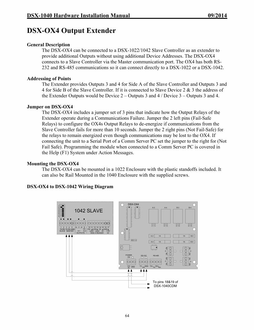
DSX-1040 Hardware Installation Manual 09/2014
64
DSX-OX4 Output Extender General Description
The DSX-OX4 can be connected to a DSX-1022/1042 Slave Controller as an extender to provide additional Outputs without using additional Device Addresses. The DSX-OX4 connects to a Slave Controller via the Master communication port. The OX4 has both RS-232 and RS-485 communications so it can connect directly to a DSX-1022 or a DSX-1042.
Addressing of Points The Extender provides Outputs 3 and 4 for Side A of the Slave Controller and Outputs 3 and 4 for Side B of the Slave Controller. If it is connected to Slave Device 2 & 3 the address of the Extender Outputs would be Device 2 – Outputs 3 and 4 / Device 3 – Outputs 3 and 4.
Jumper on DSX-OX4 The DSX-OX4 includes a jumper set of 3 pins that indicate how the Output Relays of the Extender operate during a Communications Failure. Jumper the 2 left pins (Fail-Safe Relays) to configure the OX4s Output Relays to de-energize if communications from the Slave Controller fails for more than 10 seconds. Jumper the 2 right pins (Not Fail-Safe) for the relays to remain energized even though communications may be lost to the OX4. If connecting the unit to a Serial Port of a Comm Server PC set the jumper to the right for (Not Fail Safe). Programming the module when connected to a Comm Server PC is covered in the Help (F1) System under Action Messages.
Mounting the DSX-OX4
The DSX-OX4 can be mounted in a 1022 Enclosure with the plastic standoffs included. It can also be Rail Mounted in the 1040 Enclosure with the supplied screws.
DSX-OX4 to DSX-1042 Wiring Diagram
12345678
10 11 12 13 14 15 16 171 2TX RXSLAVE
PWLED1
D0+12V1A*
3 4TX RX
MASTER
6 7 8 9
OUTPUTS
LED2LED3 D1
GND
SIDE A READER
OC5
GND A-1 A-2
1042 SLAVE
To pins 18&19 of DSX-1040CDM
A-3 A-4 B-3 B-4
1A
1A
1A
1A
POWERON
RS-232 RS-485
A-3
A-4
B-3
B-4
12VIN
GND TXRX
GND TX+TX-
RX+RX-
NO
CN
CN
OC
NC
NO
CN
CN
OC
NC
DSX-OX4

DSX-1040 Hardware Installation Manual 09/2014
65
Output Extender (Other than the DSX-OX4) General Description
The DSX-1042 Intelligent Controller allows a DSX-1043 to be connected as an extender to provide additional Outputs without using additional Device Addresses. The DSX-1043 Extender is a non-modified controller that connects to a DSX-1042 Slave controller via the Master communication port of the Slave and of the Extender. The Master communication port provides an RS-232 signal that requires 3 conductors with an overall shield and has a maximum distance of 50 feet. All of the Outputs of both the 1042 and of the Extender are available for connection.
Addressing of Points
Addressing the Extenders Outputs in the software is just like addressing points on other DSX controllers. Duplicate addresses of points are not allowed however the duplicate physical point exists and can be used. Duplicated Outputs will both Open or Secure at the same time.
Dip Switches, Firmware and Wiring The 1043 Extender requires that the addressing DIP switches of the Extender all be in the off position. The Master panel of the Location as well as the Slave that is connected to the Extender requires Firmware version 3072 or higher. Wiring of the Extender requires a cross of the communications cable between the Slave and Extender and must be within 50 feet of each other. If the Extender Module loses communications to its Slave Controller, all energized Outputs will revert to a de-energized state within 10-15 seconds of the loss.
Examples of Available Outputs
Output connections on DSX-1042 Slave include: A:1, A:2, B:1, B:2 Output Connections on 1043 Extender include: A:1 - A:8, B:1 – B:8
Note /// Duplicated Outputs will both Open or Secure at the same time. Note /// Do not use the inputs of the DSX-1043 Output Extender.
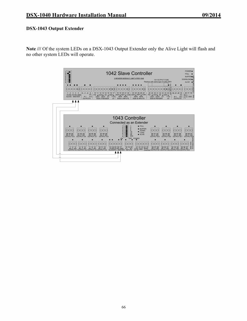
DSX-1040 Hardware Installation Manual 09/2014
66
DSX-1043 Output Extender Note /// Of the system LEDs on a DSX-1043 Output Extender only the Alive Light will flash and no other system LEDs will operate.
12345678
POWER
POLL
BUFFER
DOWNLOAD
ALIVE
12V
FU
SE
LE
D
Replace with same type 1A 3AG 250V12V OUTPUT FUSE
2 READER MODULE, LIMIT 4 PER 1048
+1
2V
INP
UT
24 25 26 2723
GND
32 33 34 3528 29 3130 40 41 42
SIDE B INPUTS
INP5INP6
INP7INP8
COM PWLED1
D0+12V1A*
LED2LED3 D1
GND
SIDE B READER
36 37 38 39
OUTPUTS
OC10 11 12 13 14 15 16 17 18 19 20 21 221 2
TX RXSLAVE
PWLED1
D0+12V1A* SIDE A INPUTS
3 4TX RX
MASTER
6 7 8 9
OUTPUTS
LED2LED3 D1
GND
SIDE A READER
INP5INP6
INP7INP8
COMOC5
GND A-1 A-2 B-1 B-2
104
2
2 D
OO
R C
ON
TR
OLL
ER
1042 Slave Controller
12345678OUTPUT A:5
NC C NO38 4039
OUTPUT A:6NC C NO41 4342
OUTPUT A:7NC C NO44 4645
OUTPUT A:8NC C NO47 4948
OUTPUT A:1NC C NO1 32
OUTPUT A:2NC C NO4 65
OUTPUT A:3NC C NO7 98
OUTPUT A:4NC C NO10 1211
OUTPUT B:1NC C NO26 2827
OUTPUT B:2NC C NO29 3130
OUTPUT B:3NC C NO32 3433
OUTPUT B:4NC C NO35 3736
OUTPUT B:8NC C NO59 6160
OUTPUT B:7NC C NO56 5857
OUTPUT B:6NC C NO53 5554
TX RX TX RX GND13 15 1614 17
SLAVE PC - MASTER
OUTPUT B:5NC C NO50 5251
DC IN+12V GND
21 22 23 24 25Relay OverrideINPUTS
A:1 B:118 2019
ON OFF
1248163264M/S
DS
X-1
043
16
Ou
tpu
t B
oar
dPOWER
POLL
BUFFERDOWN-LOADALIVE
1043 ControllerConnected as an Extender

DSX-1040 Hardware Installation Manual 09/2014
67
PC Bound Direct Communications Direct Connect Master Communications – RS-232 using DSX-USB
When the Master Controller is a DSX-1042, 1043 or 1044 the PC’s USB port or DB9 Serial Port can provide the needed RS-232 connection. DB9 Serial Port connections are provided on pages after this one.
A DSX-USB connected to the Host PC/Comm Server can supply RS-232 or RS-485 to the Master Controller. The DSX-USB terminations can provide a 50-foot length limit for RS-232 or 4000-foot length limit with its RS-485 connection. When using the RS-485 connection of the DSX-USB one must convert the RS-485 back to RS-232 before connecting to the 1040 Master Controller. Using a DSX-MCI can provide the conversion from RS-485 back to RS-232. See below.
Direct Connect Master Communications – RS-485 using DSX-USB and DSX-MCI
TX
RX
US
B to
PC
RS
-232
To
Mas
ter
RS
-485
To
Mas
ter
DSX-USB
DSX Access Systems, Inc.(800)346-5288
TX RX DTR GND
TX+ TX- RX+ RX-
Supplied CableTo PC
USB Port
DSX-1042 Master
10 11 12 13 14 15 16 17 18 19 20 21 221 2TX RXSLAVE
PWLED1
D0+12V
1A SIDE A INPUTS
3 4TX RX
MASTER
6 7 8 9
OUTPUTS
LED2LED3 D1
GND
SIDE A READER
INP5INP6
INP7INP8
COMOC5
GND A-1 A-2
PC
/M
OD
EM
12V POWERGNDRX RS232 TX RS232
RX- RS485 RX+ RS485 TX- RS485 TX+ RS485
DSX-1042 Master
10 11 12 13 14 15 16 17 18 19 20 21 221 2TX RXSLAVE
PWLED1
D0+12V
1A SIDE A INPUTS
3 4TX RX
MASTER
6 7 8 9
OUTPUTS
LED2LED3 D1
GND
SIDE A READER
INP5INP6
INP7INP8
COMOC5
GND A-1 A-2
TX
RX
USB
to P
C
RS
-232
To
Mas
ter
RS
-485
To
Mas
ter
DSX-USB
DSX Access Systems, Inc.(800)346-5288
TX RX DTR GND
TX+ TX- RX+ RX-
Supplied CableTo PC
USB Port

DSX-1040 Hardware Installation Manual 09/2014
68
Direct Connect Master Communications – RS-232 using DB9 Serial Port
The Master Controller can communicate directly with the PC via RS-232 for short distances. This method uses the RS-232 Comm Port of the PC connected to the RS-232 Master Port of the Controller. Direct RS-232 Communications are limited to 50 feet and are connected with a 22AWG 2 pair cable with an overall shield. If more than 50 feet of distance is required from the PC to Master panel two DSX-MCI modules must be used.
Direct Connect Master Communications – RS-485 using Serial Port & MCIs
When the Master Controller must be more than 50 feet from the PC the RS-232 communications can be converted to RS-485 at the PC and then back to RS-232 at the Master Controller. RS-485 Communications will support up to 4,000 feet on two twisted pair cable. This application requires two MCI modules as shown below.
Serial on Host PC
2 3 4 5
6 7 8 9
1Up to 50 feetUsing 2 pair
shielded 22 AWG
GN
D
TXRX
Female
PC to Master RS-232 Terminals of DSX-1040 Master Controller
1040 SeriesMaster
TX RXMASTER
GND
Up to 4000 feet using 2 twisted pair 22 AWG
Note /// Use Battery Backed Up Power Source For MCI's When Possible
Note /// Jumper On MCI's Should Be Placed On PC Side For This Configuration
MC
I
PC
/ M
OD
EM
MC
I
PC
/ MO
DE
M
RS-485 TX+RS-485 TX-RS-485 RX+RS-485 RX-
RS-232 TXRS-232 RXGND12V+
RS-485 TX+RS-485 TX-RS-485 RX+RS-485 RX-
RS-232 TXRS-232 RX
GND12V+
2 3 4 5
6 7 8 9
1
PC to Master RS-232 Terminals of DSX-1040 Master Controller
12VDC of SourceRX
TX
GN
DUp to 50 feet using 22 AWG, 2 Pair Shielded
Serial on Host PC
1040 SeriesMaster
TX RXMASTER
GND
12V+

DSX-1040 Hardware Installation Manual 09/2014
69
PC Bound Modem Communications Modem Operation Overview
The WinDSX system is capable of communicating with up to 32,000 locations via dial-up phone modems. Each location may be treated as a separate system, or locations may be grouped together to form a larger distributed access control system. Since the system is fully distributed and does not require a PC for operation, there is no loss of performance in systems using dial-up phone modems. All panels retain all capabilities including card access, anti-passback, and I/O Linking.
The PC may be programmed to routinely poll each modem-controlled location. Routine Polls include verification that communications are still functioning and the collection of history logs. If the PC fails to connect with a modem location on three consecutive attempts, a Location Communications Loss alarm is generated at the PC.
If the PC is not programmed to routinely poll the location Master, the Master panel will automatically store all transactions until the history buffer reaches 80% of capacity. When the buffer is at 80%, the Master panel calls the PC to upload all transactions if the PC is programmed to do so. The default settings for these two values are to poll the dialup site as often as possible, and also to dial the PC when the Transaction Buffer reaches 80% capacity.
If an alarm event occurs, the Master will initiate a call to the PC to report the alarm event regardless of its buffer status. If the Master panel is reset for any reason, it will automatically call the PC and request a full parameter download to ensure proper operation. DSX recommends the DSX series modems for dial up phone modem communications. This series of modems are small dial up phone modems that may be powered from the battery backed up 12VDC power of the DSX control panel. By powering the modem from the panel, the modem is battery backed up so that communications will occur even during an AC power loss. An external DC power transformer is supplied with each DSX modem shipped. The wire that connects the power cube to a modem can be removed and used to attach the backed up power source from the panel to the modem.
DSX configures and initializes all modems before shipping. They are shipped with everything necessary for installation. These are the only modems DSX will support. Other modems may or may not work properly. If it’s not a DSX modem you are basically on your own!!!
Phone Call Description
During an incoming call at the PC, the modem flashes the “RING” LED to indicate that the line is ringing. The Software then commands the modem to go Off-Hook. The two modems form a link and the modem lights the “DCD” LED. Communication will then proceed between the Master and the PC at the defined baud rate. The PC is always responsible for dropping the connection (hanging up the phone). The Master's modem hangs up when the connection is dropped.
The PC modem must be initialized before it will function properly. Each time the communications program is started, and before each outbound call, the modem is automatically initialized. If the modem loses power, or is turned off and then back on, it must be re-initialized. To manually re-initialize the modem, do a manual connect and disconnect or leave the communications program and return.

DSX-1040 Hardware Installation Manual 09/2014
70
Communication Security Password (Location Password)
With modem locations an optional Password can be downloaded into the Master controller. Once the Master is downloaded with the Location Password, the Password is required for all communications to that location. The Location Password entry is located under Location in the Database. Any PC communicating with a panel that has been secured with the Location Password must have the same Location Password set in its database. Changing the password requires knowledge of the password and communication with the Master panel using KB2CW.exe. The KB2C program will prompt the operator to enter the Location Password and then allow the operator to change it with the PW command. To change the password without exiting the DSX program requires completely powering the Master controller down and back up.
Modem at PC Connections
DSX-Modem to PCs USB Port using DSX-USB A DSX-USB can convert a USB port to a Serial Port. The serial port can connect to a DSX-Modem and the DSX-Modem can supply the RS-232 connection for the Master Controller. The DSX-USB derives its power from the PCs USB port.
DSX-Modem to PCs DB9 Serial Port
Use supplied modem cable to connect the modem to a Serial Port on the PC.
Supplied Cable
To PC USB Port
Up to 50 feet max.
DSX-Modem
12VDC Source
DSX-Modem at PC Back of the Female on
Cable
Phone Line
RX 2
TX 3
DTR 4
GND 5
TX
RX
US
B to
PC
RS
-232
To
Mas
ter
RS
-485
To
Mas
ter
DSX-USB
DSX Access Systems, Inc.(800)346-5288
TX RX DTR GND
TX+ TX- RX+ RX-
23
45
67
89
1
DSX-Modem
23
45
67
89
1
23
45
67
89
1
DB-9, M-F, Straight-Thru Cable
12VDC Source
DSX-Modem at PC
Up to 50 feet max.Male Female
Serial on Comm Server
Phone Line

DSX-1040 Hardware Installation Manual 09/2014
71
4321
Phone Line
DIP Switch
RS-232DB-9 To PC
DSX-Modem LED Operation
DSX-Modem to Controller Connections
The DSX-Modem converts phone line data into RS-232 or RS-485 for connectivity to a Master Controller. When the Master Controller is a DSX-1040 use the RS-232 terminals of the DSX-Modem to connect to the Controller as shown below.
Modem Power at Panel
Connect the +12V of the controller Reader Power to the +12VDC of the DSX-Modem. Connect the GND of the controller Reader Power to the GND of the DSX-Modem. If power is reversed to the modem, damage will occur.
Modem Power at PC Use the supplied 12VDC Power Source that is included with each modem. The “Stripped Wire” connects to the +12VDC of the DSX-Modem. The solid colored wire connects to GND of the modem. If power is reversed to the modem, damage will occur.
DSX-Modem Dip Switches
The dip switches control Modem Location and Speaker Mode. Located on the right side of the modem is a set of 4 switches. The switch 1 down disables the speaker, switch 1 up enables the speaker. If the DSX-Modem is located at the PC the 3 switches to the right (2-4) should be up. If the DSX-Modem is located at the Panel the 3 switches to the right (2-4) should be down.
Telephone Line Connections
Connect the Dedicated Telephone Line from the RJ-11 termination jack into the connector labeled Line. Do Not share the telephone line with any other equipment such as FAX machines or Elevator Phones. Observe proper phone line polarity. Tip/Green is Positive 48-52VDC. Red/Ring is Negative 48-52DC.
DSX-MODEMRINGDCDDTR
TX to PanelRX from Panel
POWER
DTR = Terminal (modem) ready.
TX = Normally off and turns On to indicate the Modem is sending data.
Power = Power is onRX = Normally off and turns On to indicate the Modem is receiving data.
RING = Normally off and turns On to indicate the Modem is being called.
DCD = Normally off and turns On to indicate connection established.
Up to 50 feet
PC to Master RS-232 Terminals of DSX-1040 Master Controller
MA
ST
ER
RS
-232
GNDRXTX
1040 SeriesMaster
TX RXMASTER
GNDDSX-Modem
12VDC Source
Phone Line
DSX-Modem At Master

DSX-1040 Hardware Installation Manual 09/2014
72
Initial Modem Communications Procedure
Follow these steps when establishing modem communications to a dial-up location for the first time.
To Configure the Modem in the Field
1. Confirm that all connections for the modem at the Master Panel and the modem at the PC are made according to the instructions in the Manual. The Modem at the panel should get its power from the 12 VDC card reader terminals.
2. Power the Master Panel up and wait. After initial power up the Master Panel will force the
modem off-hook and will attempt to dial out.
3. After the dialing attempt, which fails because the panel does not yet know the PCs correct phone number, unplug the Host terminal block that connects the modem and the Master Panel. This should be done at the DSX panel and not at the Modem. Now the Modem is ready to receive a call from the PC. Once the Modem at the DSX Master Panel answers, plug the Host Port terminal back into the DSX panel. This will allow the DSX panel to receive the download.
To Pre-configure the Master Controller for Modem Communications
1. To have the Master panel automatically dial out upon initial power up at the job site, the PCs phone number must be entered into the Master Panel ahead of time. The Master Panel can be connected directly to a PC or Laptop at the office or in the field and with the use of KB2CW.EXE a phone number can be programmed into non-volatile memory.
2. The panel, upon power up will automatically call the PC using the stored phone number and
request a parameter download. Start KB2CW.EXE, go to Comm Port, Define Port, Enter the Port number that is being used to connect the DSX panel to the PC or Laptop, and then click OK.
3. Press the Enter key 4-5 times, a DSX prompt (DSX>) should appear on the screen. At the
DSX prompt type in SP and press Enter. The PC phone number (up to 16 digits) can now be programmed into the non-volatile memory by typing the number and pressing Enter.

DSX-1040 Hardware Installation Manual 09/2014
73
Enclosure to Enclosure Communications Communications Overview
Enclosure to enclosure communications utilizes RS-485 between Controller Packages. RS-485 provides a fast and noise immune communications over standard 2 twisted pair wiring. The two twisted pair RS-485 circuit runs from enclosure to enclosure, CDM module to CDM module, in a series loop or daisy chain configuration. Each DSX-1040CDM module regenerates the RS-485 signal to allow up to 4,000 feet of wire between controller enclosures. The CDM has two bypass relays that will pass the RS-485 signal through to the next enclosure in case of a failure or power down.
A Star or Branch wiring configuration can be achieved with the use of a DSX-1035 Quadraplexor. The Quadraplexor provides four RS-485 outbound ports and one RS-232 port. A T-tap wiring configuration can be achieved with the use of a DSX-485T. The DSX-485T provides two RS-485 outbound ports.
Note /// Connection examples for the DSX-1035 and DSX-485T are provided in later sections of this manual.
Communications Overview Block Diagram
Note /// Any DSX Intelligent Control Panel can connect to any other DSX panel in a Master to Slave or Slave to Slave configuration.
CDM 485TCDM
103x CDM CDM
103x 102x
CDM 1035102x
CDM
CDM 103x
102x CDM
CDM
103x CDM CDM
103x 102x
CDM CDM 103x 102x CDM

DSX-1040 Hardware Installation Manual 09/2014
74
Inner Enclosure Communications (Master to Slave)
Communications between several controllers within a single enclosure such as the DSX-1048 require the connections shown below. RS-232 is required to attach at the Master Controller from the PC. The DSX-1040CDM distributes RS-232 to all controllers in the same enclosure. The DSX-1040CDM also generates RS-485 for the next enclosure or controller package. Use the connection charts on the following pages for enclosure to enclosure connections.
9 10 12 23 24 25 2613 16 17 18 19 20 21 225 6 7 271 2TX RX
SLAVES
3 4RX
8 11 14 15
MASTERTX
INTERNAL COMM
TX+ RX+TX- RX-A B C D A B C D
1048 TO 1048 COMM - WIRE OUT TO IN, TX TO RX or A-A, B-B, C-C, D-D
RX+ TX+RX- TX-
485 IN 485 OUT
+12V8A
GN
D
POWER IN
+5V.5A
GN
D
+12V1.5A
GN
D
SECONDARY OUT POWER OUTPUT, 12V 1.5A TO EACH
+12V
+12V
+12V
+12V
GN
D
GN
D
GN
D
GN
D
GN
D
1040CDM
TX RX TX RX GND1 3 42 5
SLAVE PC - MASTER
CommonA:1A:2
A:3A:4
6 8 97 10CommonA:5
A:6 A:8A:7
11 13 1412 15CommonB:1
B:2B:3
B:4
21 23 2422 25CommonB:5
B:6 B:8B:7
26 28 2927 30
DC IN+12V GND
31 32 33A:1A:2B:1B:216 1917 20
OpenCollector
OpenCollector
1044
12
V F
US
E L
ED
1042
+12
VIN
PU
T
24 25 26 2723
GND
32 33 34 3528 29 3130 40 41 42
SIDE B INPUTS
INP5INP6
INP7INP8
COM PWLED1
D0+12V
1A
LED2LED3 D1
GND
SIDE B READER
36 37 38 39
OUTPUTS
OC10 11 12 13 14 15 16 17 18 19 20 21 221 2
TX RXSLAVE
PWLED1
D0+12V
1A SIDE A INPUTS
3 4TX RX
MASTER
6 7 8 9
OUTPUTS
LED2LED3 D1
GND
SIDE A READER
INP5INP6
INP7INP8
COMOC5
GND A-1 A-2 B-1 B-2
12
V F
US
E L
ED
1042
+1
2V
INP
UT
24 25 26 2723
GND
32 33 34 3528 29 3130 40 41 42
SIDE B INPUTS
INP5INP6
INP7INP8
COM PWLED1
D0+12V
1A
LED2LED3 D1
GND
SIDE B READER
36 37 38 39
OUTPUTS
OC10 11 12 13 14 15 16 17 18 19 20 21 221 2
TX RXSLAVE
PWLED1
D0+12V
1A SIDE A INPUTS
3 4TX RX
MASTER
6 7 8 9
OUTPUTS
LED2LED3 D1
GND
SIDE A READER
INP5INP6
INP7INP8
COMOC5
GND A-1 A-2 B-1 B-2
OUTPUT A:1NC C NO1 32
OUTPUT A:2NC C NO4 65
OUTPUT A:3NC C NO7 98
OUTPUT A:4NC C NO10 1211
OUTPUT B:1NC C NO26 2827
OUTPUT B:2NC C NO29 3130
OUTPUT B:3NC C NO32 3433
OUTPUT B:4NC C NO35 3736
TX RX TX RX GND13 15 1614 17
SLAVE PC - MASTER DC IN+12V GND
21 22 23 24 25Relay OverrideINPUTS
A:1 B:118 2019
1043
MASTER
SLAVE
SLAVE
SLAVE
IF TO SLAVE MODEL #S 103X,
102X OR 1040CDM485IN, RX-
485IN, TX-
485IN, RX+
485IN, TX+
OR
PIN 5 OF DB-9 PC SERIAL
PIN 3 OF DB-9 PC SERIAL
PIN 2 OF DB-9 PC SERIALOR OR
GND OF DSX-MODEM
TX OF DSX-MODEM
RX OF DSX-MODEM
GND OF DSX-LAN
TX OF DSX-LAN
RX OF DSX-LAN
GND OF DSX-MCI
TX OF DSX-MCI
RX OF DSX-MCI
RS-232 UP TO 50 FT
OR
GND OF DSX-USB
TX OF DSX-USB
RX OF DSX-USB

DSX-1040 Hardware Installation Manual 09/2014
75
Master to Slave Communications Wiring Chart
Use the charts below for terminal to terminal wiring information on Master Enclosure to Slave Enclosure communication connections. The charts provide wiring information for each generation DSX Controller connecting to every other generation of Controller.
1040CDM w/ Master To 1021 Slave
5, TX+ 6, TX- 7, RX+ 8, RX-
43, RX+ 44, RX- 41, TX+ 42, TX-
----
1040CDM w/ Master To 1040CDM w/ Slave
5, TX+ 6, TX- 7, RX+ 8, RX-
7, RX+ 8, RX- 5, TX+ 6, TX-
----
1040CDM w/ Master To 103x Slave
5, TX+ 6, TX- 7, RX+ 8, RX-
43, RX+ 44, RX- 41, TX+ 42, TX-
----
1040CDM w/ Master To 1022 Slave
5, TX+ 6, TX- 7, RX+ 8, RX-
57, RX+ 56, RX- 59, TX+ 58, TX-
----
485 IN to 485 IN
485 IN to 485 IN
485 IN to 485 IN
485 IN to 485 IN1022 Master To 1021 Slave
59, TX+ 58, TX- 57, RX+ 56, RX-
43, RX+ 44, RX- 41, TX+ 42, TX-
----
1022 Master To 1040CDM w/ Slaves
59, TX+ 58, TX- 57, RX+ 56, RX-
7, RX+ 8, RX- 5, TX+ 6, TX-
----
1022 Master To 103x Slave
59, TX+ 58, TX- 57, RX+ 56, RX-
43, RX+ 44, RX- 41, TX+ 42, TX-
----
1022 Master To 1022 Slave
59, TX+ 58, TX- 57, RX+ 56, RX-
57, RX+ 56, RX- 59, TX+ 58, TX-
----
485 IN to 485 IN
485 IN to 485 IN
485 IN to 485 IN
485 IN to 485 IN
1021 Master To 1021 Slave
41, TX+ 42, TX- 43, RX+ 44, RX-
43, RX+ 44, RX- 41, TX+ 42, TX-
----
1021 Master To 1040CDM w/ Slaves
41, TX+ 42, TX- 43, RX+ 44, RX-
7, RX+ 8, RX- 5, TX+ 6, TX-
----
1021 Master To 103x Slave
41, TX+ 42, TX- 43, RX+ 44, RX-
43, RX+ 44, RX- 41, TX+ 42, TX-
----
1021 Master To 1022 Slave
41, TX+ 42, TX- 43, RX+ 44, RX-
57, RX+ 56, RX- 59, TX+ 58, TX-
----
485 IN to 485 IN
485 IN to 485 IN
485 IN to 485 IN
485 IN to 485 IN
103x Master To 1021 Slave
41, TX+ 42, TX- 43, RX+ 44, RX-
43, RX+ 44, RX- 41, TX+ 42, TX-
----
103x Master To 1040CDM w/ Slaves
41, TX+ 42, TX- 43, RX+ 44, RX-
7, RX+ 8, RX- 5, TX+ 6, TX-
----
103x Master To 103x Slave
41, TX+ 42, TX- 43, RX+ 44, RX-
43, RX+ 44, RX- 41, TX+ 42, TX-
----
103x Master To 1022 Slave
41, TX+ 42, TX- 43, RX+ 44, RX-
57, RX+ 56, RX- 59, TX+ 58, TX-
----
485 IN to 485 IN
485 IN to 485 IN
485 IN to 485 IN
485 IN to 485 IN

DSX-1040 Hardware Installation Manual 09/2014
76
Inner Enclosure Communications (Slave to Slave)
Communications within a single enclosure that includes only slave controllers are shown below. Communications enter the enclosure using RS-485 and terminate at the DSX-1040CDMs “485-IN” connections. The slave controllers would terminate using the CDMs RS-232 “INTERNAL SLAVES” terminals. Notice how the tx and rx cross to the rx and tx of the first slave controller then do not cross from a slave to a slave controller. Connections to other enclosures will require terminations from the “RS-485 OUT” of this enclosure to the “RS-485 IN” of the next enclosure. Use the connection charts on the following page for specific terminal connections.
9 10 12 23 24 25 2613 16 17 18 19 20 21 225 6 7 271 2TX RX
SLAVES
3 4RX
8 11 14 15
MASTERTX
INTERNAL COMM
TX+ RX+TX- RX-A B C D A B C D
1048 TO 1048 COMM - WIRE OUT TO IN, TX TO RX or A-A, B-B, C-C, D-D
RX+ TX+RX- TX-
485 IN 485 OUT
+12V8A
GN
D
POWER IN
+5V.5A
GN
D
+12V1.5A
GN
D
SECONDARY OUT POWER OUTPUT, 12V 1.5A TO EACH
+12V
+12V
+12V
+12V
GN
D
GN
D
GN
D
GN
D
GN
D
1040CDM
TX RX TX RX GND1 3 42 5
SLAVE PC - MASTER
CommonA:1A:2
A:3A:4
6 8 97 10CommonA:5
A:6 A:8A:7
11 13 1412 15CommonB:1
B:2B:3
B:4
21 23 2422 25CommonB:5
B:6 B:8B:7
26 28 2927 30
DC IN+12V GND
31 32 33A:1A:2B:1B:216 1917 20
OpenCollector
OpenCollector
1044
12V
FU
SE
LED
1042
+12
VIN
PU
T
24 25 26 2723
GND
32 33 34 3528 29 3130 40 41 42
SIDE B INPUTS
INP5INP6
INP7INP8
COM PWLED1
D0+12V
1A
LED2LED3 D1
GND
SIDE B READER
36 37 38 39
OUTPUTS
OC10 11 12 13 14 15 16 17 18 19 20 21 221 2
TX RXSLAVE
PWLED1
D0+12V
1A SIDE A INPUTS
3 4TX RX
MASTER
6 7 8 9
OUTPUTS
LED2LED3 D1
GND
SIDE A READER
INP5INP6
INP7INP8
COMOC5
GND A-1 A-2 B-1 B-2
OUTPUT A:1NC C NO1 32
OUTPUT A:2NC C NO4 65
OUTPUT A:3NC C NO7 98
OUTPUT A:4NC C NO10 1211
OUTPUT B:1NC C NO26 2827
OUTPUT B:2NC C NO29 3130
OUTPUT B:3NC C NO32 3433
OUTPUT B:4NC C NO35 3736
TX RX TX RX GND13 15 1614 17
SLAVE PC - MASTER DC IN+12V GND
21 22 23 24 25Relay OverrideINPUTS
A:1 B:118 2019
1043
SLAVE
SLAVE
SLAVE
SLAVE
IF FROM A MASTER MODEL #S 103X,
102X OR 1040CDM
IF FROM A SLAVE MODEL 1040CDM
IF FROM A SLAVE MODEL #S 103X,
102X
485IN, TX+
485IN, RX+
485IN, TX-
485IN, RX-
485OUT, RX+
485OUT, TX+
485OUT, RX-
485OUT, TX-
485OUT, TX+
485OUT, RX+
485OUT, TX-
485OUT, RX-
485IN, TX-
485IN, RX-
485IN, TX+
485IN, RX+IF TO SLAVE
MODEL #S 103X, 102X OR 1040CDM

DSX-1040 Hardware Installation Manual 09/2014
77
Slave to Slave Communications Wiring Chart
Use the charts below for terminal to terminal wiring information on Slave Enclosure to Slave Enclosure communication connections. The charts provide wiring information for each generation DSX Controller connecting to every other generation of Controller.
1021 Slave To 1021 Slave
45, TX+ 46, TX- 47, RX+ 48, RX-
41, TX+ 42, TX- 43, RX+ 44, RX-
----
485 OUT to 485 IN
1021 Slave To 1022 Slave
45, TX+ 46, TX- 47, RX+ 48, RX-
59, TX+ 58, TX- 57, RX+ 56, RX-
----
485 OUT to 485 IN
1021 Slave To 103x Slave
45, TX+ 46, TX- 47, RX+ 48, RX-
41, TX+ 42, TX- 43, RX+ 44, RX-
----
485 OUT to 485 IN
1021 Slave To 1040CDM w/ Slaves
45, TX+ 46, TX- 47, RX+ 48, RX-
5, TX+ 6, TX- 7, RX+ 8, RX-
----
485 OUT to 485 IN
103x Slave To 1021 Slave
45, TX+ 46, TX- 47, RX+ 48, RX-
41, TX+ 42, TX- 43, RX+ 44, RX-
----
103x Slave To 1040CDM w/ Slaves
45, TX+ 46, TX- 47, RX+ 48, RX-
5, TX+ 6, TX- 7, RX+ 8, RX-
----
103x Slave To 103x Slave
45, TX+ 46, TX- 47, RX+ 48, RX-
41, TX+ 42, TX- 43, RX+ 44, RX-
----
103x Slave To 1022 Slave
45, TX+ 46, TX- 47, RX+ 48, RX-
59, TX+ 58, TX- 57, RX+ 56, RX-
----
485 OUT to 485 IN
485 OUT to 485 IN
485 OUT to 485 IN
485 OUT to 485 IN
1040CDM w/ Slaves To 1021 Slave
9, RX+ 10, RX- 11, TX+ 12, TX-
41, TX+ 42, TX- 43, RX+ 44, RX-
----
1040CDM w/ Slaves To 1040CDM w/ Slaves
9, RX+ 10, RX- 11, TX+ 12, TX-
5, TX+ 6, TX- 7, RX+ 8, RX-
----
1040CDM w/ Slaves To 103x Slave
9, RX+ 10, RX- 11, TX+ 12, TX-
41, TX+ 42, TX- 43, RX+ 44, RX-
----
1040CDM w/ Slaves To 1022 Slave
9, RX+ 10, RX- 11, TX+ 12, TX-
59, TX+ 58, TX- 57, RX+ 56, RX-
----
485 OUT to 485 IN
485 OUT to 485 IN
485 OUT to 485 IN
485 OUT to 485 IN1022 Slave To 1021 Slave
55, TX+ 54, TX- 53, RX+ 52, RX-
41, TX+ 42, TX- 43, RX+ 44, RX-
----
1022 Slave To 1040CDM w/ Slaves
55, TX+ 54, TX- 53, RX+ 52, RX-
5, TX+ 6, TX- 7, RX+ 8, RX-
----
1022 Slave To 103x Slave
55, TX+ 54, TX- 53, RX+ 52, RX-
41, TX+ 42, TX- 43, RX+ 44, RX-
----
1022 Slave To 1022 Slave
55, TX+ 54, TX- 53, RX+ 52, RX-
59, TX+ 58, TX- 57, RX+ 56, RX-
----
485 OUT to 485 IN
485 OUT to 485 IN
485 OUT to 485 IN
485 OUT to 485 IN

DSX-1040 Hardware Installation Manual 09/2014
78
DSX-1035 Quadraplexor
Overview
The DSX-1035 Quadraplexor can be used as a communications multiplexor or a short haul modem. The DSX-1035 accepts RS-232 or RS-485 as input and provides four RS-485 outputs and one RS-232 output simultaneously. The 1035 has the following uses and features.
Provides multiple DSX Master to DSX Slave RS-485 communications paths at rates up
to 9600 baud. RS-232 to RS-485 converter. RS-232 or RS-485 short haul modem. The DSX-1035 Quadraplexor can transmit other data sources at rates up to 57.6K bit
over 2 twisted pair wiring for distances up to 4,000 feet. Mounting
In June of 1994, DSX released a revised edition of the 1035 Quadraplexor. This new design is smaller, more reliable, and will fit in the same enclosure as the DSX-1042. It will mount on the inside of the 1040E enclosure door. This means added savings because now the Quadraplexor does not need an enclosure of it's own, it can share one with DSX-1040 series controllers.
Grounding
The DSX-1035 must have an Earth Ground Connection for proper communications and for the internal surge protection to work.
1035 QUADRAPLEXOR
TX
TX
TX
TXRX
RX
RX
RX
OFF ON
RS485
RS232
RS232
RS232
DIAG.
OUT
IN
IN
SET 485 OR 232NOT BOTH
TX
TX
TX
TXRX
RX
RX
RX
OFF ON
PORT 1
PORT 2
PORT 3
PORT 4
16151413
TX RX GND
16.5VAC
BATTERY+ -
BATTERYFUSE
EARTHGROUND
RS232OUT
PORT 4
TX+
TX-
RX+
RX-
RS485OUT
PORT 3
TX+
TX-
RX+
RX-
RS485OUT
PORT 2
TX+
TX-
RX+
RX-
RS485OUT
PORT 1
TX+
TX-
RX+
RX-
RS485OUT
24
23
22
21
TX+
TX-
RX+
RX-
TX
RX
GND
RS-232DIAG. OUT(TX or RX)
RS485
RS232
IN
IN
8
7
6
5
4
3
2
1
28
27
26
25
32
31
30
29
20
19
18
17
1211109

DSX-1040 Hardware Installation Manual 09/2014
79
Power Requirements and Connections
1035 Terminals AC=16.5 20VA 9 and 10 Battery 12V 11 and 12 Ground 16
The DSX-1035 Quadraplexor can be powered from a DSX-1040 CDM instead of it's own transformer and battery. This can be accomplished by not connecting a transformer to the DSX-1035, but instead, connect the 12 VDC output of the 1040 CDM to the Battery (+) and (-) terminals (11 & 12) of the 1035 Quadraplexor.
Dip Switch Settings
The dipswitches on the DSX-1035 are used to set the input and output ports. The switches enable either RS-232 or RS-485 as the input. They also enable each of the four RS-485 and RS-232 output ports.
The following is a description of each dipswitch and its function. A Port is activated by placing its corresponding TX and RX switch in the On position. The On position is achieved by pressing the switch down on the right.
Do Not Enable both the RS-232 and RS-485 inputs of the DSX-1035. Only one input type can be selected at a time.
Right 8 position dip-switch Left 8 position dip-switch1. RS-485 TX IN 1. RS-485 Port 1 TX2. RS-485 RX IN 2. RS-485 Port 1 RX3. RS-232 TX IN 3. RS-485 Port 2 TX4. RS-232 RX IN 4. RS-485 Port 2 RX5. RS-232 Diag TX OUT 5. RS-485 Port 3 TX6. RS-232 Diag RX OUT 6. RS-485 Port 3 RX7. RS-232 TX OUT 7. RS-485 Port 4 TX8. RS-232 RX OUT 8. RS-485 Port 4 RX
Diagnostic Port
The Diagnostic Output of the DSX-1035 can be used to monitor the transmit or receive side of the data sent through the DSX-1035. If both the diagnostic out switches are turned On at the same time, both the transmit and receive will echo out the RS-232 diagnostic output. This Data can be monitored with a PC using KB2CW.exe from the WinDSX directory.
On = Enable Off = Disable

DSX-1040 Hardware Installation Manual 09/2014
80
Master or Slave to DSX-1035 and DSX-1035 to Master or Slave Comm Wiring Chart
Use the charts below for terminal to terminal wiring information on Controller to DSX-1035 and DSX-1035 to Controller communication connections. The charts provide wiring information for each generation DSX Controller connecting to every other generation of Controller through a DSX-1035.
1035 Quad To 1021 Master
1035 Quad To 1021 Slave
TX+ TX- RX+ RX-
43, RX+ 44, RX- 41, TX+ 42, TX-
--------
1021 Master To 1035 Quad
41, TX+ 42, TX- 43, RX+ 44, RX-
3, RX+ 4, RX- 1, TX+ 2, TX-
--------
1021 Slave To 1035 Quad
45, TX+ 46, TX- 47, RX+ 48, RX-
1, TX+ 2, TX- 3, RX+ 4, RX-
--------
51, RX+ 52, RX- 49, TX+ 50, TX-
--------
32, TX+ 31, TX- 30, RX+ 29, RX-
485 IN to 485 IN
485 OUT to 485 IN
485 OUT to 485 IN
485 OUT to 485 IN1035 Quad To 103x Master
1035 Quad To 103x Slave
TX+ TX- RX+ RX-
43, RX+ 44, RX- 41, TX+ 42, TX-
--------
103x Master To 1035 Quad
41, TX+ 42, TX- 43, RX+ 44, RX-
3, RX+ 4, RX- 1, TX+ 2, TX-
--------
103x Slave To 1035 Quad
45, TX+ 46, TX- 47, RX+ 48, RX-
1, TX+ 2, TX- 3, RX+ 4, RX-
--------
55, RX+ 56, RX- 53, TX+ 54, TX-
--------
32, TX+ 31, TX- 30, RX+ 29, RX-
485 IN to 485 IN
485 OUT to 485 IN
485 OUT to 485 IN
485 OUT to 485 IN
1035 Quad To 1022 Slave
TX+ TX- RX+ RX-
57, RX+ 56, RX- 59, TX+ 58, TX-
--------
1022 Master To 1035 Quad
59, TX+ 58, TX- 57, RX+ 56, RX-
3, RX+ 4, RX- 1, TX+ 2, TX-
--------
1022 Slave To 1035 Quad
55, TX+ 54, TX- 53, RX+ 52, RX-
1, TX+ 2, TX- 3, RX+ 4, RX-
--------
1035 Quad To 1022 Master
51, RX+ 52, RX- 49, TX+ 50, TX-
--------
32, TX+ 31, TX- 30, RX+ 29, RX-
485 IN to 485 IN
485 OUT to 485 IN
485 OUT to 485 IN
485 OUT to 485 IN
1035 Quad To 1040CDM w/ Slave
TX+ TX- RX+ RX-
7, RX+ 8, RX- 5, TX+ 6, TX-
--------
1040CDM w/ Master To 1035 Quad
5, TX+ 6, TX- 7, RX+ 8, RX-
3, RX+ 4, RX- 1, TX+ 2, TX-
--------
1040CDM w/ Slave To 1035 Quad
9, RX+ 10, RX- 11, TX+ 12, TX-
1, TX+ 2, TX- 3, RX+ 4, RX-
--------
485 IN to 485 IN
485 OUT to 485 IN
485 OUT to 485 IN

DSX-1040 Hardware Installation Manual 09/2014
81
DSX-485T Two Channel Mux/Repeater Description
The DSX-485T can be used in any RS-485 application a DSX-1035 would be used. It can split two different RS-485 Comm legs running between the Master and Slaves in a System. It can also operate as a repeater to retransmit the RS-485 communications another 4000 feet. This could be placed between enclosures to extend the panel to panel distance from 4000 to 8000 feet. The 485T requires 5VDC and RS-485.
Typical Applications
485T
4 Cond & 2 Conductor to each 485T
4 Conductor
1040CDM or 1022
1040CDM or 1022
1040CDM or 1022
1040CDM or 1022
1040CDM or 1022
RS4854000' MAX
485T 485T
4 Cond & 2 Conductor to each 485T
RS4854000' MAX
1040CDM or 1022
1040CDM or 1022
1040CDM or 1022
1040CDM or 1022
1040CDM or 1022
1040CDM or 1022
RS-485 OUTRS-485 IN
DSX-485T Rev 0
NC
NC
TX+
TX-
RX+
RX-
GND
5VTX+
TX-
RX+
RX-
TX+
TX-
RX+
RX-

DSX-1040 Hardware Installation Manual 09/2014
82
DSX-485T to Master or Slave Communications Wiring Chart
Use the charts below for terminal to terminal wiring information on Controller to DSX-485T and DSX-485T to Controller communication connections. The charts provide wiring information for each generation DSX Controller connecting to every other generation of Controller.
DSX-485T To 1021 Slave
TX+ TX- RX+ RX-
41, TX+ 42, TX- 43, RX+ 44, RX-
--------
1021 Master To DSX-485T
41, TX+ 42, TX- 43, RX+ 44, RX-
RX+ RX- TX+ TX-
--------
1021 Slave To DSX-485T
45, TX+ 46, TX- 47, RX+ 48, RX-
TX+ TX- RX+ RX-
--------
485 IN to 485 IN
485 OUT to 485 IN
485 OUT to 485 INDSX-485T To 103x Slave
TX+ TX- RX+ RX-
41, TX+ 42, TX- 43, RX+ 44, RX-
--------
103x Master To DSX-485T
41, TX+ 42, TX- 43, RX+ 44, RX-
RX+ RX- TX+ TX-
--------
103x Slave To DSX-485T
45, TX+ 46, TX- 47, RX+ 48, RX-
TX+ TX- RX+ RX-
--------
485 IN to 485 IN
485 OUT to 485 IN
485 OUT to 485 IN
DSX-485T To 1040CDM w/ Slave
TX+ TX- RX+ RX-
7, TX+ 8, TX- 5, RX+ 6, RX-
--------
1040CDM w/ Master To DSX-485T
5, TX+ 6, TX- 7, RX+ 8, RX-
RX+ RX- TX+ TX-
--------
1040CDM w/ Slave To DSX-485T
9, RX+ 10, RX- 11, TX+ 12, TX-
TX+ TX- RX+ RX-
--------
485 IN to 485 IN
485 OUT to 485 IN
485 OUT to 485 INDSX-485T To 1022 Slave
1022 Master To DSX-485T
59, TX+ 58, TX- 57, RX+ 56, RX-
RX+ RX- TX+ TX-
--------
1022 Slave To DSX-485T
55, TX+ 54, TX- 53, RX+ 52, RX-
TX+ TX- RX+ RX-
--------
485 IN to 485 IN
485 OUT to 485 IN
TX+ TX- RX+ RX-
59, TX+ 58, TX- 57, RX+ 56, RX-
--------
485 OUT to 485 IN

DSX-1040 Hardware Installation Manual 09/2014
83
KB2CW.exe Terminal Emulation / IP Comm Port Program Overview
There are a number of parameters that can be changed and set in the non-volatile memory of the controller. These parameters can be viewed and changed without the use of the software. One of these parameters is the Baud Rate. The panels are pre-set to communicate to the PC at 9600 baud. The panel to panel communications is also pre-set to 9600 baud and cannot be changed. The Location number can also be changed to a number higher than the dip-switch will allow. The PCs phone number and the modem initialization string can also be viewed and changed. The Location Password can also be changed in this terminal mode of operation. In order to view or change data stored in the panel, use a dumb terminal or a PC running a terminal emulation program such as KB2CW.exe. This is accomplished by connecting the serial port of the Master Panel to the serial port on a Laptop or PC. Use the terminal emulation program that accompanies the WinDSX software. This terminal emulation program is called KB2CW.exe and is in the WinDSX directory. KB2CW.exe does not need the WinDSX software to operate and can be copied to a Laptop or PC not containing the software. The following will show the steps required to view and change some of the panel settings using a PC running the terminal emulation program KB2CW.exe on Comm Port 1.
To Run KB2CW.exe
1. Make the necessary connections from the PC to the Master as a direct connect system.
Also verify that the mode dip switch(es) on the Master are set with 8 On (Master Direct Connect).
2. Using Windows Explorer locate the WinDSX directory and the KB2CW.exe file and
double click on it.
Select Comm Port from the menu at the top and set the port number to match the port used. Then set the Baud Rate to 9600, Word to 8, Stop Bits 1, and Parity to None. The program should return a message that displays the port, baud, data length, stop bit setting and show a single line flashing cursor. If you receive a message that says: “Port Could Not Be Initialized”, there is a hardware problem with the PC that must be corrected before communications can occur.
3. Press the Enter key three times. You should then see a DSX> prompt returned from the Master panel. If you do not get this prompt, refer to the trouble shooting section of this manual.
4. Once you have the DSX> prompt, type “?” and then press ( Enter). This will show the
command list from the Master panel. The panel will return the following:

DSX-1040 Hardware Installation Manual 09/2014
84
Valid Commands:
Command Description ? Command List (Displays the Command List) V Version & Misc. (Show Firmware Version and Stored Parameters) CR Card Reader (Show Data Received on Card Reader Ports) TD Dump (List All Memory Tables) RR Record Dump (Used in Development Only) LO Enter Location (Set Location Number to 128 and up) MD Memory Dump (List all Memory Addresses) RE Reset modem defaults (Reset Init and Baud to Factory Defaults) MI Enter Modem Init Seq. (Customize Modem Initialization Sequence) SP Set Host Phone (Program Phone Number of Host PC) MF Mem Fill (Used in Development Only) EM Enter Mode (Used in Development Only) DI Dump Inputs (Used in Development Only) CS Dump Table Checksums (Used in Development Only) PW Enter Password (Used to Change the Location Password at the Master) BU Set Busy Flag (Used in Development Only) ST Stats (Used in Development Only)
To Display Current Settings Type: “V” and press Enter (DSX>V) The Following information is displayed:
Version 3157 Built : Nov 12 2007. 15:03:54 Version Date 12/28/2007 7:55:2 Fri Current Time 2/21/2002 8:7:43 Thur Addr Master 2 DIP Switch 10000010 Phone PC's phone number here Modem/Lan Baud 9600 9600 Modem Default +++~~~AT|ATZ|~~~ATM1Q1E0S0=3&D0&K0\N0|~ATDT% Modem Current +++~~~AT|ATZ|~~~ATM1Q1E0S0=3&D0&K0\N0|~ATDT% Cyc/sec 359 Polls/sec 59 Missed Polls 0 Stack (sz, fre, seq, sp) 4096 2338 1567 3952 24928 29024 1428 Test Results Cycles : 0 Errors : 0 RamK 512 Cpu/ioBrd 1 6 (1042) Rdr types 48 65 Dnld secs 57 57 Link RBQ(re, wd, mx, ec) 74 38 1 0 EEprom 0 Busy : 128 D Busy Nodes (flags, minutes, maxMinutes) : Bytes/Code: 3 Old Firmware EXISTS!!!! Sender supports FAST TABLES Max Follow Secs: 0 Sys Table Memory Bytes 495078 Table CheckSums PC : 0 Local : 10112808 Delta: 10112808

DSX-1040 Hardware Installation Manual 09/2014
85
To Change Baud Rate
1. Within the 1040 and 1022 Intelligent Controllers the baud rate is preset at 9600 and cannot be altered. Within the 103x and 1021 Intelligent Controllers one can type MB and then press Enter. The Master panel will respond with a message that says: Enter New Baud Rate: Type in the desired baud rate that you wish the Master panel to use and press Enter. Acceptable baud rates are 1200, 2400, or 9600. The new baud rate will be permanently stored in the EEPROM of the 103x or 1021 Master panel and in the Flash Firmware of the 1040 and 1022 controllers. This information will be retained even after the panel is powered down.
2. To verify the new baud rate in panels redefine the port using the new baud rate. Check to
make sure that the modem information is set properly. The modem baud rate is the baud rate for both direct and modem communications.
3. When all changes are verified select File and Exit.
4. At the PC, set the Comm port baud rate to match the baud rate set in the Master panel.
The PC Comm port baud rate is defined in Comm Port Parameters under System/Setup. The modem baud rate is the baud rate for both direct and modem communications.
Default Baud Rates Note /// WinDSX software and 521 or higher firmware has a default baud of 9600.
Note /// DSX-1042, 1043, 1044 and DSX-1022 Controllers are set at a minimum and maximum of 9600 baud and cannot be altered.

DSX-1040 Hardware Installation Manual 09/2014
86
Changing the Modem Initialization String in the Master Panel
1. You may customize the modem initialization sequence sent by the Master. This may be necessary when modems, other than those recommended by DSX, are used in the system. To change the modem initialization sequence, type in MI and then press Enter. The Master panel will return Enter Init Sequence: Type in the initialization sequence that you want to be sent to the modem and press Enter.
2. To view the stored modem initialization sequence, type V and then press Enter. The
default init string is the initialization string stored in the firmware. The current init string is the one that is stored in non-volatile memory and is the one currently used.
3. Type MI to set the current modem init string as shown, when finished press (Enter).
+++~~~AT|ATZ|~~~ATM1Q1E0S0=3&D0&K0\N0|~ATDT% If you make a mistake, you must start over by pressing (Enter) and then MI (Enter). When complete press (Enter) and type V (Enter) to check for the new "current" init string. (0 = Zero)
4. To quit select File and Exit. Reconnect the modem and power the panel down and back up.
Modem Speaker Volume
To disable the modem speaker, substitute M0 for M1 in the MIS string. To increase the volume of the speaker, add L2 to the MIS string leaving M1 in the string.
Resetting the Modem
When making the above changes it may be necessary to reset the modem before the changes will work properly. To do this, use KB2CW.exe from the WinDSX directory and connect the modem to the PC's serial port. Run the KB2CW.exe program by double clicking on it through Windows Explorer. Select Comm Port from the menu. Enter the appropriate port number and baud rate (9600, 8, 1, N) and click OK. Next type AT&F and press Enter. The modem should respond “OK”. It may take several attempts at resetting the modem for it to respond “OK”.
Restricting Dial-out from Controller
To prevent the controller from ever dialing out to the PC, remove the ATDT% from the panels modem initialization string. This is performed with KB2CW.exe using the instructions above regarding changing the modem initialization string in the master panel.

DSX-1040 Hardware Installation Manual 09/2014
87
Leased Line Modems
Leased line modems may be used with the DSX System between the PC and the Master or between the Master and Slave panels. A leased line connection is essentially the same as “direct wire” as far as the system is concerned. There are no special system programming considerations for leased line modems. When ordering a leased line for use with the DSX System, you should specify the following items:
2 or 4 wire circuit (depending on the modem you are using, 2 wire for DSX modems) Analog
The communications parameters used in all aspects of the DSX System that apply to leased line modems are:
9600 Baud 8 bit word No parity 1 stop bit Asynchronous
There are many leased line modems that are compatible with these parameters. Be sure to select a modem that will automatically re-establish a connection if it is ever disconnected. This will prevent having to manually reconnect the modems any time there is a short break in service from the Phone Company.
There are other ways to communicate between the PC and the Master or between the Master and Slave panels. Fiberoptics and microwave are examples of how this communication can be achieved. The above parameters apply regardless of the method of communication.
Note /// It is important when using leased line modems or other equipment that these devices do not buffer, perform data compression, error checking, or alter the flow of data in any way. DSX Leased Line Modems
DSX Leased Line Modems are available pre-configured for two wire leased line connections or point to point communications. The modems will automatically reconnect when reset. Use the following diagrams for connections of the DSX leased line modems. The Leased Line and Dial Line modems are shipped with different cosmetic case fronts as well as stickers on the top of the modems to indicate where the modem should be placed on the telephone line. If a DSX “Originate” or “Answer” Leased Line modem were to fail and require a replacement, a new “Originate” or “Answer” must be specified in the order. Placement of the leased line modems is specific, the “Originate” modem should be placed nearest the Master Panel and the “Answer” modem should be placed farthest away from the Master Panel.
Leased Line Characteristics The Leased Line requirements fit the past standard of the “Bell 3002-Type” line characteristic. Since deregulation few if any carriers still refer to them as such, although they have lines with the same characteristics under their own definition.
How to Order a Leased Line: The telephone line should be an analog 2-wire, unconditioned leased line engineered with an end-to-end loss of about 16 dB. Thus, the receive-end signal strength will be about a minus 25 dBm. However, our modems will work just fine at even lower receive levels. DSX modems are normally configured (default setting) to transmit at a minus 9 dBm on

DSX-1040 Hardware Installation Manual 09/2014
88
either a dial line or leased line. A voice grade line will usually pass frequencies from about 400 hertz to 3400 hertz.
Note /// DSX dial line modems cannot be used in place of a DSX Leased Line modem and a DSX Leased Line modem cannot be used in place of DSX Dial Line modem. These modems cannot be reconfigured to operate as the other type of modem.
DSX Lease Line Modem Operation
DSX Modems are available pre-configured for two wire leased line connections or point to point communications. The modems will automatically reconnect when reset. Follow the diagrams below to connect the DSX modems for two-wire leased line operation.
Connecting a Master to a Slave Panel with DSX Leased Line Modems
Note /// Connecting a Slave to a Slave Panel and feeding a Slave from a Quadraplexor with DSX Leased Line Modems are within the following pages.
Note /// The communications line is crossed when leaving master. Communications line is also crossed feeding into a
slave panel.
Notice position of J1 & J2
jumpers on MCI.T
X+
TX
-R
X+
RX
-
+1
2VD
CG
ND
LEASED LINE
MR TR SD RD OH CD AA HS
ORIGINATE
TX
+T
X-
RX
+R
X-
+1
2VD
CG
ND
LEASED LINE
MR TR SD RD OH CD AA HS
ANSWER
Frontof
Modem
1040CDM With The Master Controller
5 6 7 9 10 11 12485 IN 485 OUT
8TX+ TX- RX+ RX-
A B C DRX+ RX- TX+ TX-
A B C DCAN TO CAN COMM - WIRE OUT TO IN, TX - RX or A-A, B-B, C-C, D-D
TO 12VDC SOURCE
5 6 7 9 10 11 12485 IN 485 OUT
8TX+ TX- RX+ RX-
A B C DRX+ RX- TX+ TX-
A B C DCAN TO CAN COMM - WIRE OUT TO IN, TX - RX or A-A, B-B, C-C, D-D
TO 12VDC SOURCE
1040CDM With Only Slave Controllers
TIP RING
61
RJ11RECIEVER
3 4
TO
MCI MCI
Power SwitchPressed IN = ON
Power ConnectorCenter point is positive
RJ11Reciever
MCI Connects Here
Leave Jumper across PINs
1&2Back of Modem

DSX-1040 Hardware Installation Manual 09/2014
89
Connecting a Slave to another Slave Panel using DSX Leased Line Modems
Note /// The communications line is crossed when leaving master. Communications line is also crossed feeding into a
slave panel.
TX
+T
X-
RX
+R
X-
+1
2VD
CG
ND
LEASED LINE
MR TR SD RD OH CD AA HS
ORIGINATE
TX
+T
X-
RX
+R
X-
+1
2VD
CG
ND
LEASED LINE
MR TR SD RD OH CD AA HS
ANSWER
Frontof
Modem
1040CDM With Only Slave Controllers
TO 12VDC SOURCE
5 6 7 9 10 11 12485 IN 485 OUT
8TX+ TX- RX+ RX-
A B C DRX+ RX- TX+ TX-
A B C DCAN TO CAN COMM - WIRE OUT TO IN, TX - RX or A-A, B-B, C-C, D-D
TO 12VDC SOURCE
1040CDM With Only Slave Controllers
TIP RING
61
RJ11RECIEVER
3 4
TO
9 10 11 12 13 14 15485 OUT
RX+ RX- TX+ TX-A B C D
+12VDC
GN
D10APOWER IN
GN
D
MCI MCI
Power SwitchPressed IN = ON
Power ConnectorCenter point is positive
RJ11Reciever
MCI Connects Here
Leave Jumper across PINs
1&2Back of Modem

DSX-1040 Hardware Installation Manual 09/2014
90
Connecting a Quadraplexor (1035) to a Slave Panel using DSX Leased Line Modems
1035 QUADRAPLEXOR
TX
TX
TXRX
RX
RX
RX
OFF ON
RS485
RS232
RS232
RS232
DIAG.
OUT
IN
IN
16151413
TX RX GND
16.5VAC
BATTERY+ -
BATTERYFUSE
EARTHGROUND
RS232OUT
TX+
TX-
RX+
RX-
TX
RX
GND
RS-232DIAG. OUT(TX or RX)
RS485
RS232
IN
IN
8
7
6
5
4
3
2
1
1211109
SET 485 OR 232NOT BOTH
TX
2
3
7
Note /// The communications line is crossed when leaving master. Communications line is also crossed feeding into a
slave panel.
5 6 7 9 10 11 12485 IN 485 OUT
8TX+ TX- RX+ RX-
A B C DRX+ RX- TX+ TX-
A B C DCAN TO CAN COMM - WIRE OUT TO IN, TX - RX or A-A, B-B, C-C, D-D
1040CDM With Only Slave Controllers
TIP RING
61
RJ11RECIEVER
3 4
TO
LEASED LINE
MR TR SD RD OH CD AA HS
ORIGINATELEASED LINE
MR TR SD RD OH CD AA HS
ANSWER
Frontof
Modem
TX
+T
X-
RX
+R
X-
+1
2VD
CG
ND
MCI
PC / MODEM
TO 12VDC SOURCE
Power SwitchPressed IN = ON
Power ConnectorCenter point is positive
RJ11Reciever
MCI Connects Here
Leave Jumper across PINs
1&2Back of Modem
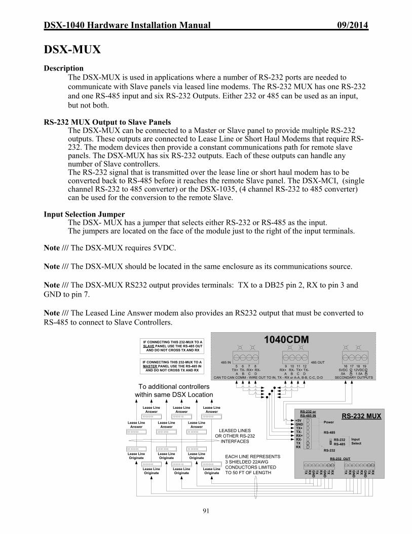
DSX-1040 Hardware Installation Manual 09/2014
91
DSX-MUX Description
The DSX-MUX is used in applications where a number of RS-232 ports are needed to communicate with Slave panels via leased line modems. The RS-232 MUX has one RS-232 and one RS-485 input and six RS-232 Outputs. Either 232 or 485 can be used as an input, but not both.
RS-232 MUX Output to Slave Panels
The DSX-MUX can be connected to a Master or Slave panel to provide multiple RS-232 outputs. These outputs are connected to Lease Line or Short Haul Modems that require RS-232. The modem devices then provide a constant communications path for remote slave panels. The DSX-MUX has six RS-232 outputs. Each of these outputs can handle any number of Slave controllers. The RS-232 signal that is transmitted over the lease line or short haul modem has to be converted back to RS-485 before it reaches the remote Slave panel. The DSX-MCI, (single channel RS-232 to 485 converter) or the DSX-1035, (4 channel RS-232 to 485 converter) can be used for the conversion to the remote Slave.
Input Selection Jumper
The DSX- MUX has a jumper that selects either RS-232 or RS-485 as the input. The jumpers are located on the face of the module just to the right of the input terminals.
Note /// The DSX-MUX requires 5VDC. Note /// The DSX-MUX should be located in the same enclosure as its communications source. Note /// The DSX-MUX RS232 output provides terminals: TX to a DB25 pin 2, RX to pin 3 and GND to pin 7. Note /// The Leased Line Answer modem also provides an RS232 output that must be converted to RS-485 to connect to Slave Controllers.
EACH LINE REPRESENTS 3 SHIELDED 22AWG CONDUCTORS LIMITED TO 50 FT OF LENGTH
TX+TX-
RX-RX+
+5VGND
TXRX
RS-232RS-485
Power
RS-485
RS-232
InputSelect
RX
TX
GN
D
RX
TX
GN
D
RX
TX
RX
TX
GN
D
RX
TX
RS-232 OUT
RS-232 or RS-485 IN RS-232 MUX
GN
D
RX
TX
Lease LineOriginate
Lease LineOriginate
Lease LineOriginate
Lease LineOriginate
Lease LineOriginate
Lease LineOriginate
Lease LineAnswer
Lease LineAnswer
Lease LineAnswer
Lease LineAnswer
Lease LineAnswer
Lease LineAnswer
LEASED LINESOR OTHER RS-232
INTERFACES
To additional controllers within same DSX Location
5 6 7485 IN
8TX+ TX- RX+ RX-
A B C DCAN TO CAN COMM - WIRE OUT TO IN, TX - RX or A-A, B-B, C-C, D-D
1040CDMIF CONNECTING THIS 232-MUX TO ASLAVE PANEL USE THE RS-485 OUT
AND DO NOT CROSS TX AND RX
16 17 18 195VDC
GN
D
GN
D.5A12VDC
1.5ASECONDARY OUTPUTS
9 10 11 12485 OUT
RX+ RX- TX+ TX-A B C D
IF CONNECTING THIS 232-MUX TO AMASTER PANEL USE THE RS-485 IN
AND DO NOT CROSS TX AND RX

DSX-1040 Hardware Installation Manual 09/2014
92
TCP/IP Communications
WinDSX Software version 2.0.0 and higher has the ability to redirect Master communications that are normally connected to a serial port to a TCP/IP address. A LAN/WAN serial server device with that same TCP/IP address is then connected to the network in the same or different building and its RS-232 output is connected to a DSX Master Controller.
DSX-LAN Interface Module
Overview The DSX-LAN(M) module is typically used to connect a Master Controller to the Comm Server PC over a Local or Wide Area Network. The WinDSX software is inherently TCP/IP capable and can redirect communications that would normally be transmitted out a serial port, over a LAN/WAN to a particular IP address. The DSX-LAN(M) module receives that communication and converts it to RS-232 or RS-485 that connects directly to the Master Controller. The DSX-LAN(M) module is sold in two different configurations. With the DSX-LAN, IP communications is the only method of connectivity. The DSX-LAN(M) has dial-up modem backup. The DSX-LAN module must be ordered with the (M) option along with the DSX modem to support the dial-up backup feature.
Other Applications
The DSX-LAN can also be used at Slave Controllers with the use of the PC Master Software. PC Master is a DSX software application that emulates a Master Controller. PC Master gets its download from the Comm Server PC and communicates with all of the Slaves just like a Master Controller does. What is different about the PC Master software is its ability to communicate with each Slave Controller via TCP/IP or with a serial port connection. This allows Slave Controllers to be placed on the LAN and each one or each group of Controllers to have a LAN connection using a DSX-LAN module. Modem backup is not available for Slave Controller communication.
Dial-up Modem Backup The DSX-LAN(M) module has a 9 pin serial port that is used to connect a DSX modem for communications redundancy. When the DSX-LAN(M) module determines a loss of network connectivity it switches to “Modem Mode” which allows the Master Controller to call the Comm Server or Host PC via the modem when necessary. When the Network connection is re-established the Master Controller reconnects over the LAN. The modem and the DSX-LAN(M) module are powered from the Controller and are connected to each other via the supplied serial cable. Call for availability of this feature. Programming the System and the DSX-LAN module is broken down into Three phases. The First is the WinDSX Configuration. The Second is the DSX-LAN Module Programming and the Third is Commissioning the Module.
I. WinDSX Software Configuration Configuring the WinDSX software for IP communications to a Location Master Controller is simple and requires just a few steps.
1. In DataBase - Edit the Location and select the Numeric Options Tab.

DSX-1040 Hardware Installation Manual 09/2014
93
2. Set the Connect Type to Direct and click on OK to save.
3. In DataBase select
System/Setup and then Comm Ports.
4. Define (add) a Comm Port
above the Range of physical ports.
5. Set the Port Type to LAN
(TCP/IP).
6. Enter the static IP Address to be assigned to the DSX-LAN module in the TCP/IP Address field. Consult with the Network administrator for this address.
7. Enter the TX IP Port # that will be programmed into the DSX-LAN module.
WinDSX will communicate to the DSX-LAN module that is programmed with the TCP/IP Address and TX IP Port Number defined here.
8. The RX IP Port # can be
used if desired. If left at 0 the Comm Server will use the next available port to communicate with the DSX-LAN module and will expect a reply to that port. By specifying exactly what ports are used, unused ports can be blocked for security reasons.
II. DSX-LAN Module Programming Programming the DSX-LAN module is very simple and easy to do. Connect to the unit with a PC or Laptop and program the unit with KB2CW.exe through a serial port. This is the recommended method of programming the unit.
Programming Through a Serial Port Connection 1. Connect the Master RS-232 port of the DSX-LAN module to a serial port on a PC or
Laptop running KB2CW.exe. Power the module with 12VDC from either the Master Controller or other source.
2. From within the WinDSX folder double click on KB2CW.exe.
3. Select Comm Ports / Define Ports and enter the port number that the DSX-LAN
module is attached to. Use all other defaults and click on OK.

DSX-1040 Hardware Installation Manual 09/2014
94
4. Once the Port information is displayed, type !!! (3 exclamation points). If properly
connected through a working serial port the unit will return a message of: Please Type Password followed by the Enter Key
Enter 123456 and press Enter.
5. Now Press the number 2 and the unit will prompt you to enter its IP Address. Enter the static or reserved address for this unit including the dots between each octet. (example = 172.25.16.136) Press Enter and then press Enter a second time to confirm the entry.
6. Now Press the number 3 and the unit will prompt you to enter its IP Port Number.
Enter the port to be used (between 4001 and 5000). This must be the same IP Port number that was previously entered for the Comm Port definition under the TX IP Port # field. Press Enter and then press Enter a second time to confirm the entry.
7. Now Press the number 5 and the unit will prompt you to enter it into the Static or
Dynamic mode. Press 1 to set it for Dynamic and Press Enter and then press Enter a second time to confirm the entry.
8. Now Press the number 6 and the unit will prompt you to enter a new Password.
Enter up to 6 alphanumeric characters that will be required to reprogram the unit. Press Enter and then press Enter a second time to confirm the entry.
9. Now Press the number 7 and the unit will prompt you to enter a Link Type. Leave at
0 for Auto-negotiation, 1 = 100Mb/Full Duplex, 2 = 10Mb/Full Duplex, [Select 1 or 2 for Cisco routers] Press Enter and then press Enter a second time to confirm the entry. For more information see next page.
10. Now Press the letter S to Save the changes and exit the programming mode or press
X to exit without saving the changes.
11. Select File and Exit in KB2CW and the unit is ready for use.
12. Connect the Master RS-232 Port of the DSX-LAN module to the Master RS-232 Port of the Master Controller. Be sure to cross the TX and RX between the Module and the Master Controller.
Cisco Switch / VLAN Applications When attaching the DSX-LAN module to a Cisco Layer 2 Switch or in a VLAN Scenario it is best to have the network administrator issue a new IP Address for the DSX-LAN module. When using this type of network equipment the MAC address of the DSX-LAN will have to be explicitly programmed into the switching Equipment by the Network Administrator.
Example of DSX-LAN Programming

DSX-1040 Hardware Installation Manual 09/2014
95
III. Commissioning the Module
Once WinDSX is configured and the DSX-LAN module is programmed and installed at the Master Controller there are a few final steps necessary to commission the module.
1. Close the WinDSX program at the Comm Server.
2. Open a Command Prompt at the Comm Server PC and Ping the DSX-LAN module’s IP address. This Step has to be performed at the Comm Server! If you ping the unit from a different PC you will need to Reset the DSX-LAN to factory defaults (see below) and start completely over.
For Example: (Type the following at the command line. _ = space) Ping_172.25.16.136 (and then Press Enter.) If the unit replies, commissioning the unit was successful.
3. Close the Command Prompt and Restart the WinDSX program at the Comm Server.
Resetting the DSX-LAN to factory defaults
To reset the unit and default it to no IP Address and 4444 as the IP Port number – press the reset button on the side of the DSX-LAN module and hold it until the LAN TX LED lights up and then extinguishes.
Q&A Why don’t I need a subnet mask or default gateway?
Because the DSX-LAN Module is an appliance. It is not a network card nor is it a router. It is a device used to communicate with DSX Panels. The premise here is that the Comm Server talks to the DSX-LAN module first. Once the DSX-LAN module receives a packet that was intended for it, the module simply replies to that packet. Since the DSX-LAN module does not initiate the conversation it does not need the typical information that a network pc or a router would require in order to initiate a conversation with another network device.
Can I use a DSX-LAN Module even though I have a DHCP server? Yes, but the DSX-LAN Module has to have a fixed IP address just like the DSX Comm Server. The address that you use for the DSX-LAN Module has to be excluded from your DHCP scope.
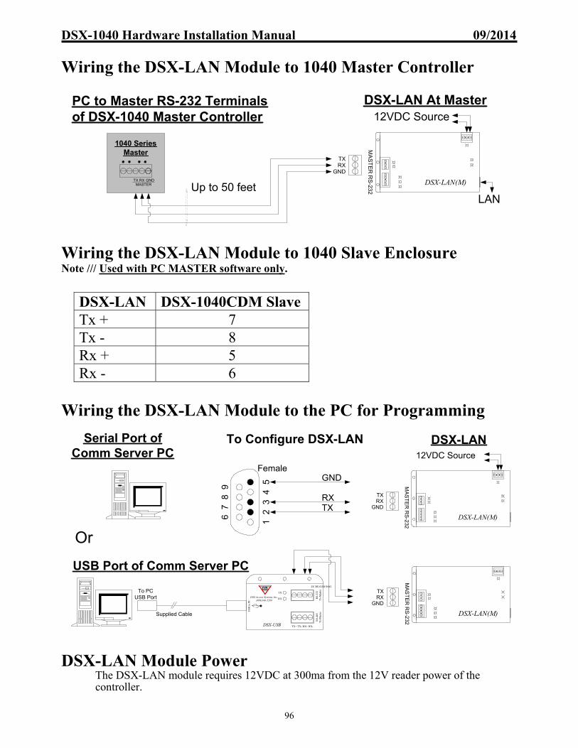
DSX-1040 Hardware Installation Manual 09/2014
96
Wiring the DSX-LAN Module to 1040 Master Controller
Wiring the DSX-LAN Module to 1040 Slave Enclosure Note /// Used with PC MASTER software only.
Wiring the DSX-LAN Module to the PC for Programming
DSX-LAN Module Power The DSX-LAN module requires 12VDC at 300ma from the 12V reader power of the controller.
DSX-LAN DSX-1040CDM Slave Tx + 7 Tx - 8 Rx + 5 Rx - 6
DSX-LAN(M)
DSX-LAN At Master12VDC Source
Up to 50 feetLAN
PC to Master RS-232 Terminals of DSX-1040 Master Controller
MA
ST
ER
RS
-232
GNDRXTX
1040 SeriesMaster
TX RXMASTER
GND
DSX-LAN(M)
DSX-LAN12VDC Source
MA
ST
ER
RS
-232
GNDRXTX
Serial Port of Comm Server PC
To Configure DSX-LAN
Supplied Cable
To PC USB Port
TX
RX
USB
to P
C
RS-
232
To
Mas
ter
RS-
485
To
Mas
ter
DSX-USB
DSX Access Systems, Inc.(800)346-5288
TX RX DTR GND
TX+ TX- RX+ RX-
USB Port of Comm Server PC
23
45
67
89
1
FemaleGND
RXTX
DSX-LAN(M)
MA
ST
ER
RS
-232
GNDRXTX
Or

DSX-1040 Hardware Installation Manual 09/2014
97
Fiber Optic Communications
WinDSX Software has the ability to direct communications through fiber optic transmitters and receivers. Fiber optic cable and equipment may be used to extend the distance that communications can travel from PC to Master Panel, Master Panel to Slave Panel or from a Slave Panel to another Slave. DSX has been tested with several brands of fiber optic equipment. Within the next several pages we will show with diagrams what has operated well within accepted tolerances for communications. Other combinations and manufacturers offer similar products that may and may not operate as well as those shown. Units shown may even require calls to those manufacturers Technical Support lines for assistance.
Host to Master Panel with IFS
Distances
The distance between a Host DSX-USB module and the first ifs D1315 must be as short as possible. A few inches would be best even though the terminals are identified as RS-485. The distance the fiber can transmit from D1315 to D1315 can be no longer than 2.5 miles. The distance between the second D1315 unit and the Master panel must be as short as possible even though the terminals are identified as RS-485 lines. At the last ifs D1315 unit one must install a 120 ohm resistor across the Data Input lines as shown in the diagram above.
D13154 WIRE RS485
POWER
D-6GND-5
D-4D-3
GND-2D-1
DATAOUTPUT
DATAINPUT
GRD-212VAC/12VDC-1
POWER
InternationalFiberSystemsIncorporated
DATAREC
DATAXMTR
D13154 WIRE RS485
POWER
D-6GND-5
D-4D-3
GND-2D-1
DATAOUTPUT
DATAINPUT
GRD-212VAC/12VDC-1POWER
InternationalFiberSystemsIncorporated
DATAREC
DATAXMTR
TO 12VDC/12VAC SOURCE
To 12VDC/12VAC Supply
IFS D1315 Fiber Optic Interfaces
DSX-USB MODULEAT COMM SERVER PC
Fiber Optic CableLength Limit = 2.5 mile maximum
120 ohmrequired
by ifs
203-428-1180
203-428-1180
Length Limit:As Short as Possible
TX
+T
X -
RX
-R
X +
MCI
+12
VD
C-1
2VD
CR
XT
X
-12
VD
C+
12V
DC
TO
12V
DC
SO
UR
CE
1040 SeriesMaster
TX RXMASTER
GND
TX
RX
USB
to P
C
RS-
232
To
Mas
ter
RS
-485
To
Mas
ter
DSX-USB
DSX Access Systems, Inc.(800)346-5288
TX RX DTR GND
TX+ TX- RX+ RX-
Supplied Cable
TO USB PORTOF COMM SERVER
-DATA - 4OUTPUT
INPUT
+DATA - 3-DATA - 2+DATA - 1
EXAMPLE OF NEWER IFS UNIT
PICTURED IS OLDERIFS UNIT
NOTE /// NEWER UNIT EXAMPLE ABOVE.
Length Limit:As Short as Possible
Len
gth
Lim
it:L
ES
S T
HA
N 5
0FT
.

DSX-1040 Hardware Installation Manual 09/2014
98
Master to Slave Panel Using IFS
Distances
The distance between the DSX-1040CDM and the first ifs D1315 must be as short as possible. A few inches would be best even though the terminals are identified as RS-485. The distance the fiber can transmit from D1315 to D1315 can be no longer than 2.5 miles. The distance between the second D1315 unit and the next Slave panel must be as short as possible even though the terminals are identified as RS-485 lines. At the last ifs D1315 unit one must install a 120 ohm resistor across the Data lines as shown in the diagram above.
Note /// Several IFS fiber optics units require the purchase of a specific power source for the fiber interface. Not using the recommended power source may cause non-repairable damage to the unit.
Fiber Optic Technical Support
American Fibertek – (732) 302-0660, http://www.americanfibertek.com Communications Specialties, Inc. – (631) 273-0404, http://www.commspecial.com IFS (International Fiber Systems Inc.) – (203) 426-1180, http://www.ifs.com
D13154 WIRE RS485
D-6GND-5
D-4D-3
GND-2D-1
DATAOUTPUT
DATAINPUT
GRD-212VAC/12VDC-1POWER
InternationalFiberSystemsIncorporated
DATAREC
DATAXMTR
To 12VDC/12VAC Supply
Fiber Optic CableLength Limit = 2.5 mile maximum
203-428-1180
1040CDM Master Controller
9 10 125 6 7 8 11TX+ RX+TX- RX-
A B C D A B C DRX+ TX+RX- TX-
485 IN 485 OUT
EXTERNAL TO 1048J1J2
COMMUNICATION
D13154 WIRE RS485
POWER
D-6GND-5
D-4D-3
GND-2D-1
DATAOUTPUT
DATAINPUT
GRD-212VAC/12VDC-1POWER
InternationalFiberSystemsIncorporated
DATAREC
DATAXMTR
To 12VDC/12VAC Supply
120 ohmrequired
by ifs203-428-1180
IFS D1315 Fiber Optic Interfaces
1040CDM Slave Controller
9 10 125 6 7 8 11TX+ RX+TX- RX-
A B C D A B C DRX+ TX+RX- TX-
485 IN 485 OUT
EXTERNAL TO 1048J1J2
COMMUNICATION
NOTE /// NOTICE POSITION OF J1 & J2 (MASTER/SLAVE) JUMPERS ON 1040CDM
NOTE /// NOTICE POSITION OF J1 & J2 (MASTER/SLAVE) JUMPERS ON 1040CDM
POWER
PICTURED IS OLDER IFS UNITNOTE /// NEWER UNIT EXAMPLE BELOW
-DATA - 4OUTPUT
INPUT
+DATA - 3-DATA - 2+DATA - 1
EXAMPLE OF NEWER IFS UNIT

DSX-1040 Hardware Installation Manual 09/2014
99
Slave to Slave Panel Using IFS
Distances
The distance between the DSX Slave and the first ifs D1315 must be as short as possible. A few inches would be best even though the terminals are identified as RS-485. The distance the fiber can transmit from D1315 to D1315 can be no longer than 2.5 miles. The distance between the second D1315 unit and the next Slave panel must be as short as possible even though the terminals are identified as RS-485 lines. At the last ifs D1315 unit one must install a 120 ohm resistor across the Data lines as shown in the diagram above.
Note /// Several IFS fiber optics units require the purchase of a specific power source for the fiber interface. Not using the recommended power source may cause non-repairable damage to the unit.
Fiber Optic Technical Support
American Fibertek – (732) 302-0660, http://www.americanfibertek.com Communications Specialties, Inc. – (631) 273-0404, http://www.commspecial.com IFS (International Fiber Systems Inc.) – (203) 426-1180, http://www.ifs.com

DSX-1040 Hardware Installation Manual 09/2014
100
DSX-1035 to Slave Panel Using IFS
Distances
The distance of wire from 1035 to IFS and IFS to CDM should be as short as possible. The distance the fiber can transmit from D1315 to D1315 can be no longer than 2.5 miles. At the last ifs D1315 unit one must install a 120 ohm resistor across the Data lines as shown in the diagram above.
Note /// Several IFS fiber optics units require the purchase of a specific power source for the fiber interface. Not using the recommended power source may cause non-repairable damage to the unit. Fiber Optic Technical Support
American Fibertek – (732) 302-0660, http://www.americanfibertek.com Communications Specialties, Inc. – (631) 273-0404, http://www.commspecial.com IFS (International Fiber Systems Inc.) – (203) 426-1180, http://www.ifs.com
To 12VDC/12VAC Supply
Fiber Optic CableLength Limit = 2.5 mile maximum
NOTE /// NOTICE POSITION OF J1 & J2 (MASTER/SLAVE) JUMPERS ON 1040CDM.
NOTE /// NOTICE THIS NEWER D1315 TERMINATES DIFFERENTLY COMPARED TO OLDER UNITS.
- DATA-4+ DATA-3- DATA-2+ DATA-1
OUTPUT
INPUT
GRD-212VAC/12VDC-1
POWER
DATAREC
DATAXMTR
POWER
- DATA-4+ DATA-3- DATA-2+ DATA-1
OUTPUT
INPUT
GRD-212VAC/12VDC-1
POWER
DATAREC
DATAXMTR
POWER
1040CDM Slave Controller
9 10 125 6 7 8 11TX+ RX+TX- RX-
A B C D A B C DRX+ TX+RX- TX-
485 IN 485 OUT
EXTERNAL TO 1048J1J2
COMMUNICATION
TX+
TX-
RX+
RX-
RS485OUT
1035 QUADRAPLEXOR
To 12VDC/12VAC Supply
120 ohmrequired
by ifs
D13154 WIRE RS485
InternationalFiberSystemsIncorporated
203-428-1180
D13154 WIRE RS485
InternationalFiberSystemsIncorporated
203-428-1180

DSX-1040 Hardware Installation Manual 09/2014
101
Slave to Slave Panel Using CSI 5012
Note /// Several of the diagrams regarding fiber optics require the purchase of a specific power source for the fiber interface. Not using the recommended power source may cause non-repairable damage to the unit. Note /// The distance between the DSX Controller and the fiber optic interface units must be as short as possible. A few inches would be best even though the terminals are identified as RS-485. The distance the fiber can transmit from unit to unit may vary depending on manufacturer. Fiber Optic Technical Support
American Fibertek – (732) 302-0660, http://www.americanfibertek.com Communications Specialties, Inc. – (631) 273-0404, http://www.commspecial.com IFS (International Fiber Systems Inc.) – (203) 426-1180, http://www.ifs.com
1040CDM Slave Controller
9 10 125 6 7 8 11TX+ RX+TX- RX-
A B C D A B C DRX+ TX+RX- TX-
485 IN 485 OUT
EXTERNAL TO 1048J1J2
COMMUNICATION
1040CDM Slave Controller
9 10 125 6 7 8 11TX+ RX+TX- RX-
A B C D A B C DRX+ TX+RX- TX-
485 IN 485 OUT
EXTERNAL TO 1048J1J2
COMMUNICATION
12
1234
65
To 10 -18VDC Power Supply
12
1234
65
To 10 -18VDC Power Supply
+
-
+
-Note /// DIP Sw.settings: Mode Sw (8Pos) = 1&5 OnT/R Sw (6Pos) = 4 OnAll others = Off
Note /// DIP Sw.settings: Mode Sw (8Pos) = 1&5 OnT/R Sw (6Pos) = 4 OnAll others = Off
CSI MATH 5012 CSI MATH 5012
Fiber Optic Interfaces

DSX-1040 Hardware Installation Manual 09/2014
102
Master to Slave Panel Using American Fibertek MR-485-4
Note /// The distance between the DSX Controller and the fiber optic interface units must be as short as possible. A few inches would be best even though the terminals are identified as RS-485. The distance the fiber can transmit from unit to unit may vary depending on manufacturer. Note /// Several of the previous diagrams regarding fiber optics require the purchase of a specific power source for the fiber interface. Not using the recommended power source may cause non-repairable damage to the unit. Fiber Optic Technical Support
American Fibertek – (732) 302-0660, http://www.americanfibertek.com Communications Specialties, Inc. – (631) 273-0404, http://www.commspecial.com IFS (International Fiber Systems Inc.) – (203) 426-1180, http://www.ifs.com
Multi-Mode
OpticalCable
American Fibertek Inc Fiber Optic Transciever
Model MR-485-4
24VAC
2345
24VAC
485 Input +485 Input -
485 Output +485 Output -
Master to SlaveRS-485
Communications
Note /// Wires between Controller and Transciever should be as short as possible.
24VAC Power Source
1040CDM Slave Controller
9 10 125 6 7 8 11TX+ RX+TX- RX-
A B C D A B C DRX+ TX+RX- TX-
485 IN 485 OUT
EXTERNAL TO 1048J1J2
COMMUNICATION
1040CDM Master Controller
1
Ground
American Fibertek Inc Fiber Optic Transciever
Model MT-485-4
24VAC
2345
24VAC
485 Input +485 Input -
485 Output +485 Output -
1
Ground
Ground
Ground24VAC Power Source
9 10 125 6 7 8 11TX+ RX+TX- RX-
A B C D A B C DRX+ TX+RX- TX-
485 IN 485 OUT
EXTERNAL TO 1048J1J2
COMMUNICATION

DSX-1040 Hardware Installation Manual 09/2014
103
Slave to Slave Panel Using American Fibertek MX485-4
Note /// Several of the previous diagrams regarding fiber optics require the purchase of a specific power source for the fiber interface. Not using the recommended power source may cause non-repairable damage to the unit. Note /// The distance between the DSX Controller and the fiber optic interface units must be as short as possible. A few inches would be best even though the terminals are identified as RS-485. The distance the fiber can transmit from unit to unit may vary depending on manufacturer. Fiber Optic Technical Support
American Fibertek – (732) 302-0660, http://www.americanfibertek.com Communications Specialties, Inc. – (631) 273-0404, http://www.commspecial.com IFS (International Fiber Systems Inc.) – (203) 426-1180, http://www.ifs.com
TX
RX
American Fibertek Transciever
Model MX485-412VDC+ 200MA Max1
23456
NegativeData Input +Data Input -Data Output +Data Output -
TX
RX
American Fibertek Transciever
Model MX485-412VDC+ 200MA Max1
23456
NegativeData Input +Data Input -Data Output +Data Output -
Slave to SlaveRS-485
Communications
Note /// Wires between Controller and Transciever should be as short as possible.
PS-12 Power Source 12vdc 200ma
Fiber Optic CableLength Limit = 10,000 ft. maximum
Note /// This American FiberTek unit requires a 100 - 220 Ohm 1/4w EOL to stabilize the Input line.
PS-12 Power Source 12vdc 200ma
1040CDM Slave Controller
9 10 125 6 7 8 11TX+ RX+TX- RX-
A B C D A B C DRX+ TX+RX- TX-
485 IN 485 OUT
EXTERNAL TO 1048J1J2
COMMUNICATION
1040CDM Slave Controller
9 10 125 6 7 8 11TX+ RX+TX- RX-
A B C D A B C DRX+ TX+RX- TX-
485 IN 485 OUT
EXTERNAL TO 1048J1J2
COMMUNICATION
DSX-1040 Hardware Installation Manual 09/2014
104
Card Plus PIN / Card Or PIN Controlling Door on DSX-1042 DSX offers several products that can operate in the Card Plus PIN and several that operate in Card Or PIN. Below we will describe the difference in operation along with the correct DSX Part Number to purchase. Be cautious when ordering due to the model being specific to operation. For wiring of the products please refer to the proper “Card Reader Port” section later in this manual. Card Plus PIN is used to control entry that requires a Card read “Plus” a PIN entry. DSX will use the Timezone assignments for “Reader TZ” and “Keypad TZ” for when each portion is required for entry. We will refer to DSX Part numbers which will include a “dash 8” at the end for Card Plus PIN. Card Or PIN is used to control entry that requires a card read or a keypad entry to unlock the door. We will refer to DSX Part numbers which will include a “dash 26” at the end for Card Or PIN.
Manufacturer DSX Card Plus PIN Part Numbers DSX Card Or PIN Part Numbers Essex DS-12-8W, DS-12-8C, DS-12-SL8,
PiezoProx-8 DS-12-26, DS-12-SL26, PiezoProx-26
HID ID-PK5355-8 ID-PK5355-26 HID iClass/SE 6130-8, 6136-8 6130-26, 6136-26 Indala FP-5061B-8 FP-5061B-26 Pyramid P-600-8 P-600-26 XceedID / AptiQ
XF2110 is -8 by default from Mfgr. Can be programmed in the field. See Reader Port section for specifics.
-8 Card Plus PIN: To configure the system for Card + PIN: Under Location / Yes-No Options select “Enable Card + PIN Operation” and under Numeric Options “Number of digits in PIN Code” allows a number 4 thru 7. Under Device a Time Zone must be assigned for Reader TZ and Keypad TZ to determine when only a card read is required and when it requires a Card Read plus a PIN to Grant Access. Where the Reader and Keypad Time Zones are active at the same time the system requires both card plus PIN and when the Reader TZ is the only active TZ the system only requires a card. Within each Cardholder record / Cards-Phone#-Key / Cards; one must apply the “Code #” and “PIN#” plus an Access Level. To operate the system in Card + PIN: The -8 reader will require a card read when only the Reader TZ is active but would require a card read and a 4-7 digit PIN be entered when the Reader and Keypad TZs are both active. -26 Card Or PIN: To configure the system for Card or PIN: The number to be entered at the keypad must be a cardholders code number and must be within the range of 1-65,535. To operate the system in Card or PIN: The –26 Keypad requires a code be entered when the Reader TZ is active. After pressing the number on the keypad the # key must be pressed. Note /// In the -26 scenario a PIN is added to the Cardholder record as a Code# and the PIN field remains empty.

DSX-1040 Hardware Installation Manual 09/2014
105
Inside & Outside Reader Controlling Same Door on DSX-1042
To control one door with two readers, keep track of who is In or Out of the building, and /or enforce anti-passback, make the following wiring connections. To complete this application, use the programming examples below this diagram. If you are not tracking In and Out status or using anti-passback, connect both readers to the same side of the panel. It is allowable to connect more than one reader to any reader port.
Programming and Operation
The Lock and the Door Position Switch connect to side A and side A programs as normal. On side B, Relay 1 is connected to the Exit Request Input 8 on side A. The Unlock Time for side B is programmed for 1 second. Relay 1 on Side B momentarily trips the Exit Request on Side A, which unlocks the door and bypasses Input 7 as normal. If using Anti-passback, the reader on the inside of the building is the Out Reader, and the reader on the outside of the building is the In Reader.
Database Menu Data Field Name Side A Side B
Device Unlock Time as desired 1 second
Device Use Input 7 & 8 Yes No
Device Door Open too Long as desired N/A
Device In, Out, or Neutral In - optional Out - optional
Device Exit Request Unlocks Yes N/A
Device Link Granted Events –Output 1
Yes Yes
Output Relay Time Zone as desired 24 hour
1K E
OL
22
BLA
CK
RE
D
GR
EE
N
WH
ITE
OR
AN
GE
SHIELD
PR
EW
AR
N (-10
0MA
)
BLA
CK
RE
D
GR
EE
N
WH
ITE
SHIELD17
RE
Q. +
VD
C F
RO
M 10
42
TO +VDC FROM 1042
DOORCONTACTS
1K
EO
L
1042 Side A & B
36 37 38 39
NC C NO
B-2OUTPUT B-1
SIDE B OUTPUTS
28 29 30 31 32 33 34 35
LED1 LED3 D1LED2 D0 GND
+12VDCPRE
SIDE B READER PORT
23 24 25 26 27
SIDE B INPUTS
INP5INP6
INP7INP8
COM18 19 20 21 22
SIDE A INPUTS
INP5INP6
INP7INP8
COM10 11 12 13 14 15 16 17
LED1 LED3 D1LED2 D0 GND
+12VDCPRE
SIDE A READER PORT
6 7 8 9
NC C NO
A-2OUTPUT A-1
SIDE A OUTPUTS
37 3832 33 34 3520 21 2210 12 13 14 15 16 177 8
MAG LOCK
MOV
1040 PDMLOCK 1 - 4
GND +VDC (Rev7 - 9)
11
BR
OW
N
13 LED3
12 LED2 ORANGE
11 LED1 BROWN
OUTSIDE READER INSIDE READER

DSX-1040 Hardware Installation Manual 09/2014
106
Man-Trap Applications Note /// The diagram on the next page details the recommended connections for this application.
This page describes how to implement a “Man-Trap” Application using outputs 1 and 2 on both sides of a DSX-1042 Controller. The Man-Trap application described could be on a vestibule that has an inner and outer door. The purpose of this application is that if one door is open or unlocked the other must not un-lock. Utilizing a DSX-1042 Controller, Side A would be designated for the Outer door and Side B for the Inner door. The wiring diagram shows outputs 1 and 2 wired in parallel to control the lock. This configuration applies to both sides of the controller. In addition Connect the NC side of relay 1:B to the lock wire attached to the NO side of relay 1:A. Connect the NC side of relay 1:A to the lock wire attached to the NO side of relay 1:B.
Programming:
1. Program both devices with the following settings: A. Link Granted Events to Output 1– Yes, B. Door Open Detect Relock – Yes, C. Use Input 7 & 8 – Yes, D. Unlock Time 30 seconds
2. Program Output 2 on both sides with no time zone. Program Output 2 on both sides to link secure. Create a separate linking group for each Output 2 and set the response type to follow.
3. Program Output 1 on both sides of the controller with a 24-hour time zone. Program Output 1 on side A to Perform Link when Open and Link to the linking group that consists of relay 2 on side B. Program Output 1 on side B to Perform Link when Open and Link to the linking group that consists of relay 2 on side A. Any time a door unlocks it links to relay 2 on the opposite side which overrides unlock relay 1 for the other door. When this door relocks the link to Output 2 on the other side is reset.
4. Program input 7 on side A to link on a status change to the linking group that consists of Output 2 on side B. Program input 7 on side B to link on a status change to the linking group that consists of Output 2 on side A. Any time a door is open it links to Output 2 on the opposite side which overrides unlock relay 1 for the other door. When this door is shut the link to Output 2 on the other side is dropped.
Note /// The door must be both shut and locked before the other door can unlock. Program the unlock time long enough so that the card does not have to be re-read if the opposite door has the lock overridden. Once the other door shuts and locks the current door will release.

DSX-1040 Hardware Installation Manual 09/2014
107
Man-Trap Applications - Connections
12V
FU
SE
LE
D
Replace with same type 1A 3AG 250V12V OUTPUT FUSE
2 READER MODULE, LIMIT 4 PER 1048DSX-1042
+12
VIN
PU
T
24 25 26 2723
GND
32 33 34 3528 29 3130 40 41 42
SIDE B INPUTS
INP5INP6
INP7INP8
COM PWLED1
D0+12V
1A
LED2LED3 D1
GND
SIDE B READER
36 37 38 39
OUTPUTS
OC10 11 12 13 14 15 16 17 18 19 20 21 221 2
TX RXSLAVE
PWLED1
D0+12V
1A SIDE A INPUTS
3 4TX RX
MASTER
6 7 8 9
OUTPUTS
LED2LED3 D1
GND
SIDE A READER
INP5INP6
INP7INP8
COMOC5
GND A-1 A-2 B-1 B-2
EXTERNAL RELAY
DryContacts
N C NC O O
+ 12V
- GND
Relay Coil
12V Relay
NO
EXIT BUTTON
Fail Safe Lock
MOV
1040 PDMLOCK 1 - 4
GND +VDC
Lock Power Source
(Rev7-9)
MOV
NO
EXIT BUTTON
MOV
1040 PDMLOCK 1 - 4
GND +VDC
Lock Power Source
(Rev7-9)
Fail Safe Lock
MOV
DOOR CONTACTS
DOOR CONTACTSEXTERNAL
RELAY
DryContacts
N C NC O O
+ 12V
- GND
Relay Coil
12V Relay

DSX-1040 Hardware Installation Manual 09/2014
108
Special Applications The following are fully described at: http://www.dsxinc.com/DesignGuide2/index.htm
Virtual Outputs in the WinDSX system are outputs that do not physically exist but can be programmed in the same manner as any Relay Output in the system. Virtual Outputs can be used for Time Zone control, linking, process control, bell schedules, fail safe timers and many more applications.
First Man In can be implemented to prevent doors that normally unlock on a schedule from unlocking when weather or other conditions prevent anyone from traveling to or occupying the location or building. The Time Zone that normally unlocks the door is overridden until a card is first used to gain access to the building. This could be a regular or manager assigned card at any reader or a particular one.
Manager First can be used to keep other employees cards from gaining access to the building when the manager is not on site. Certain Access Levels would be disabled until a manager arrived and used their card thereby enabling those Access Levels of the subordinates.
The Two Man Rule requires that two different cardholders must use their card before they can gain access to a door. This could be set up for any two card holders or it could be taken a step farther so that for example a card holder from Group A and one from Group B must both use their card for the door to unlock.
Access Level Control can restrict and/or change Access Levels on the card population without the need for lengthy downloads. This can be done for card control at a university that needs to shut off or restrict access to its student population during the holidays and will support different time requirements for the different classes of the student population. It can also be used in Threat Level Management to change the accessibility of the card holders.
Threat Level Management accommodates the quick reconfiguration of a system required for Emergencies without the need of programming or lengthy downloads. Hazmat Lockdowns will typically secure all the doors in an area or the entire facility not allowing anyone or just particular personnel access in or out. Threat Level Management can go a bit further reconfiguring the system by Securing Outputs (locking doors), restricting Device (reader) access, altering Access Levels, arming Input points, enabling Image Recall and more.
Hazmat Lockdown accommodates the quick lockdown of a system required for Hazmat alerts. The Lockdowns occur without the need of programming or lengthy downloads. Hazmat Lockdowns will typically secure all the doors in an area or the entire facility not allowing anyone or just particular personnel access in or out.
Time Zone Control can quickly disable one Time Zone and/or enable another through Time Zone Linking. There are times when an application calls for multiple schedules to control cards or door locks with the ability to switch from one schedule to another without any programming or Time Zone reassignment. This could be a manager card being used at a reader that switches a door from one locking schedule (Time Zone) to another or clicking on an Output Icon in the Workstation software

DSX-1040 Hardware Installation Manual 09/2014
109
Time Display Module (TDM & TDM5)
Overview The Module is typically used in Time and Attendance applications where the time must be displayed to those who are clocking in or out. DSX offers 2 sizes of Time Display Module. The original unit provides a 1”x 4” display, the new unit provides a 5”x16” display. Each Modules uses 4-each 7-segment LED displays. The Time Display Module can be connected to the Master or Slave Controller and is updated once a minute by the Master Controller. With firmware 3157 and higher the Time Display Module can be connected to a single Controller system.
Application The collection of time using DSX requires a minimum of 2 readers. The readers are defined as Time and Attendance In or Time and Attendance Out under Device in the Database section of the Software. Using WinDSX a History report can provide the total time that persons were clocked in. The report can be displayed, printed or exported to formats used by Third Party software that calculate pay rates. A common practice regarding the placement of the hardware includes the readers to be located in a commons area of the facility. Another is to mount the TDM near the Time and Attendance readers.
Power Power requirements of the TDMs differ of the 2 units. The TDM (1-inch display) can connect to a power source within the controller hardware as it requires 12vdc at 160ma. The TDM5 (5-inch display) requires a 16.5vac 40VA XFMR and cannot be connected to the DSX controller for power.
Mounting Mounting the TDM requires the surface mounting of a backplane, the addition of the circuit board, front bezel and end caps. The TDM backplane design provides holes for mounting and wire penetration to the circuitry. The completed TDM assembly totals 1 pound total weight and measures 2 5/8 x 5 ¼ inches. Mounting the TDM5 also requires surface mounting of a backplane, the addition of the circuit board, front bezel and end caps. The TDM5 enclosure however does not provide mounting holes or wire penetration for the circuitry. The mounting of the TDM5 will require some on-site engineering. The completed TDM5 assembly totals 6.5 pounds of weight and measures 8 3/8 x 18 inches.
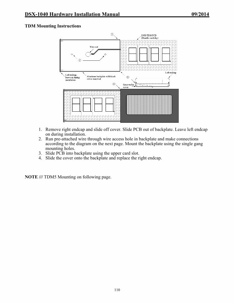
DSX-1040 Hardware Installation Manual 09/2014
110
TDM Mounting Instructions
1. Remove right endcap and slide off cover. Slide PCB out of backplate. Leave left endcap on during installation.
2. Run pre-attached wire through wire access hole in backplate and make connections according to the diagram on the next page. Mount the backplate using the single gang mounting holes.
3. Slide PCB into backplate using the upper card slot. 4. Slide the cover onto the backplate and replace the right endcap.
NOTE /// TDM5 Mounting on following page.
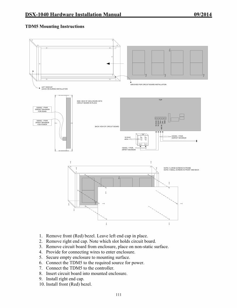
DSX-1040 Hardware Installation Manual 09/2014
111
TDM5 Mounting Instructions
1. Remove front (Red) bezel. Leave left end cap in place. 2. Remove right end cap. Note which slot holds circuit board. 3. Remove circuit board from enclosure, place on non-static surface. 4. Provide for connecting wires to enter enclosure. 5. Secure empty enclosure to mounting surface. 6. Connect the TDM5 to the required source for power. 7. Connect the TDM5 to the controller. 8. Insert circuit board into mounted enclosure. 9. Install right end cap. 10. Install front (Red) bezel.
18AWG, 1 PAIR, 25FEET MAXIMUM
FOR POWER
22AWG, 1 PAIR, 500FEET MAXIMUM
FOR RS485
LEFT ENDCAP,LEAVE ON DURING INSTALLATION
GROOVES FOR CIRCUIT BOARD INSTALLATION
NOTE /// LARGE SCREWS IN FRAMENOTE /// SMALL SCREWS IN FRONT AND BACK
SIDE VIEW OF ENCLOSURE WITH CIRCUIT BOARD IN PLACE
16.
5V
AC
16.
5V
AC
485
IN
GN
D
RX
+
RX
-
TOP
18AWG, 1 PAIR, 25FEET MAXIMUM
22AWG, 1 PAIR, 500FEET MAXIMUM
BACK VIEW OF CIRCUIT BOARD
16.5VAC40VA

DSX-1040 Hardware Installation Manual 09/2014
112
TDM Wiring Diagram
If using WinDSX 3.1.X and lower there must be at least one Slave controller in the system for the TDM to function. If using WinDSX 3.5.X and higher a TDM can be attached to a Direct Connected Master or a Slave Controller. Firmware 3157 and higher allow a TDM to connect to a modem or direct connected single panel Location.
TDM Wiring on a CDM with Master Controller and Slaves
Note /// More options are shown in the following pages regarding TDMs.
9 10 12 23 24 25 2613 16 17 18 19 20 21 225 6 7 271 2TX RX
SLAVES
3 4RX
8 11 14 15
MASTERTX
INTERNAL COMM
TX+ RX+TX- RX-A B C D A B C D
1048 TO 1048 COMM - WIRE OUT TO IN, TX TO RX or A-A, B-B, C-C, D-D
RX+ TX+RX- TX-
485 IN 485 OUT
+12V8A
GN
D
POWER IN
+5V.5A
GN
D
+12V1.5A
GN
D
SECONDARY OUT POWER OUTPUT, 12V 1.5A TO EACH
+12V
+12V
+12V
+12V
GN
D
GN
D
GN
D
GN
D
GN
D
1040CDMJ1J2
SET J1 & J2 AS"MAS" MASTER IF THERE IS A MASTER CONTROLLER IN THIS 1048.
SET J1 & J2 AS "SLAVE" IF THERE IS NOT A MASTER CONTROLLER IN THIS 1048.
SLAVE MAS
4 conductor shielded, Max 500 feet from Controller.
(TDM)
BlackRed
WhiteGreen
NOTE /// Use these connections when Master is present in this enclosure.
NOTE /// Notice position of jumpers J1 & J2 of CDM
(TDM5)
NOTE /// Size Difference of TDMsTDM = 1 inch numbersTDM5 = 5 inch numbers
9 10 12 23 24 25 2613 16 17 18 19 20 21 225 6 7 271 2TX RX
SLAVES
3 4RX
8 11 14 15
MASTERTX
INTERNAL COMM
TX+ RX+TX- RX-A B C D A B C D
1048 TO 1048 COMM - WIRE OUT TO IN, TX TO RX or A-A, B-B, C-C, D-D
RX+ TX+RX- TX-
485 IN 485 OUT
+12V8A
GN
D
POWER IN
+5V.5A
GN
D
+12V1.5A
GN
D
SECONDARY OUT POWER OUTPUT, 12V 1.5A TO EACH
+12V
+12V
+12V
+12V
GN
D
GN
D
GN
D
GN
D
GN
D
1040CDMJ1J2
SET J1 & J2 AS"MAS" MASTER IF THERE IS A MASTER CONTROLLER IN THIS 1048.
SET J1 & J2 AS "SLAVE" IF THERE IS NOT A MASTER CONTROLLER IN THIS 1048.
SLAVE MAS
16.5
VA
C
16.5
VA
C 485
IN
GN
D
RX
+
RX
-
22AWG, 1 PAIR, 500 FEET MAXIMUM
18AWG, 1 PAIR, 25 FEET MAX.
NOTE /// Requires Firmware 3157 or higher.
22AWG, 1 PAIR, 500 FEET MAXIMUM
16.5VAC 40VATRANSFORMER
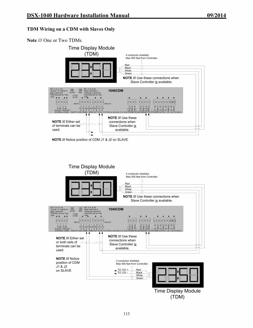
DSX-1040 Hardware Installation Manual 09/2014
113
TDM Wiring on a CDM with Slaves Only Note /// One or Two TDMs
9 10 12 23 24 25 2613 16 17 18 19 20 21 225 6 7 271 2TX RX
SLAVES
3 4RX
8 11 14 15
MASTERTX
INTERNAL COMM
TX+ RX+TX- RX-A B C D A B C D
1048 TO 1048 COMM - WIRE OUT TO IN, TX TO RX or A-A, B-B, C-C, D-D
RX+ TX+RX- TX-
485 IN 485 OUT
+12V8A
GN
D
POWER IN
+5V.5A
GN
D+12V1.5A
GN
D
SECONDARY OUT POWER OUTPUT, 12V 1.5A TO EACH
+12V
+12V
+12V
+12V
GN
D
GN
D
GN
D
GN
D
GN
D
1040CDMJ1J2
SET J1 & J2 AS"MAS" MASTER IF THERE IS A MASTER CONTROLLER IN THIS 1048.
SET J1 & J2 AS "SLAVE" IF THERE IS NOT A MASTER CONTROLLER IN THIS 1048.
SLAVE MAS
4 conductor shielded, Max 500 feet from Controller.
Time Display Module(TDM)
BlackRed
WhiteGreen
NOTE /// Use these connections when Slave Controller is available.
NOTE /// Use these connections when Slave Controller is
available.
NOTE /// Either set of terminals can be used.
NOTE /// Notice position of CDM J1 & J2 on SLAVE
9 10 12 23 24 25 2613 16 17 18 19 20 21 225 6 7 271 2TX RX
SLAVES
3 4RX
8 11 14 15
MASTERTX
INTERNAL COMM
TX+ RX+TX- RX-A B C D A B C D
1048 TO 1048 COMM - WIRE OUT TO IN, TX TO RX or A-A, B-B, C-C, D-D
RX+ TX+RX- TX-
485 IN 485 OUT
+12V8A
GN
D
POWER IN
+5V.5A
GN
D
+12V1.5A
GN
D
SECONDARY OUT POWER OUTPUT, 12V 1.5A TO EACH
+12V
+12V
+12V
+12V
GN
D
GN
D
GN
D
GN
D
GN
D
1040CDMJ1J2
SET J1 & J2 AS"MAS" MASTER IF THERE IS A MASTER CONTROLLER IN THIS 1048.
SET J1 & J2 AS "SLAVE" IF THERE IS NOT A MASTER CONTROLLER IN THIS 1048.
SLAVE MAS
4 conductor shielded, Max 500 feet from Controller.
Time Display Module(TDM)
BlackRed
WhiteGreen
NOTE /// Use these connections when Slave Controller is available.
4 conductor shielded, Max 500 feet from Controller.
Time Display Module(TDM)
BlackRed
WhiteGreen
NOTE /// Use these connections when Slave Controller is
available.
TO 12V +TO 12V -
NOTE /// Either set or both sets of terminals can be used.
NOTE /// Notice position of CDM J1 & J2 on SLAVE

DSX-1040 Hardware Installation Manual 09/2014
114
Multiple TDMs on CDM with Slave Controller Only Note /// Four TDMs on one CDM
Note /// Six TDMs using 485T
9 10 12 23 24 25 2613 16 17 18 19 20 21 225 6 7 271 2TX RX
SLAVES
3 4RX
8 11 14 15
MASTERTX
INTERNAL COMM
TX+ RX+TX- RX-A B C D A B C D
1048 TO 1048 COMM - WIRE OUT TO IN, TX TO RX or A-A, B-B, C-C, D-D
RX+ TX+RX- TX-
485 IN 485 OUT
+12V8A
GN
D
POWER IN
+5V.5A
GN
D
+12V1.5A
GN
D
SECONDARY OUT POWER OUTPUT, 12V 1.5A TO EACH
+12V
+12V
+12V
+12V
GN
D
GN
D
GN
D
GN
D
GN
D
1040CDMJ1J2
SET J1 & J2 AS"MAS" MASTER IF THERE IS A MASTER CONTROLLER IN THIS 1048.
SET J1 & J2 AS "SLAVE" IF THERE IS NOT A MASTER CONTROLLER IN THIS 1048.
SLAVE MAS
NOTE /// CDM J1 & J2 jumpers to the side marked SLAVE.
GR
EE
N
WH
ITE
BL
AC
K
RE
D
GR
EE
N
WH
ITE
BL
AC
K
RE
D
12VDC+
12VDC-
12VDC+
12VDC-
NOTE /// Limit 2 TDMs per RS485 port.
NOTE /// Each TDM draws 160ma
BL
AC
K
RE
D
BL
AC
K
RE
D
GR
EE
N
WH
ITE
GR
EE
N
WH
ITE
12VDC+
12VDC-
12VDC+
12VDC-
9 10 12 23 24 25 2613 16 17 18 19 20 21 225 6 7 271 2TX RX
SLAVES
3 4RX
8 11 14 15
MASTERTX
INTERNAL COMM
TX+ RX+TX- RX-A B C D A B C D
1048 TO 1048 COMM - WIRE OUT TO IN, TX TO RX or A-A, B-B, C-C, D-D
RX+ TX+RX- TX-
485 IN 485 OUT
+12V8A
GN
D
POWER IN
+5V.5A
GN
D
+12V1.5A
GN
D
SECONDARY OUT POWER OUTPUT, 12V 1.5A TO EACH
+12V
+12V
+12V
+12V
GN
D
GN
D
GN
D
GN
D
GN
D
1040CDMJ1J2
SET J1 & J2 AS"MAS" MASTER IF THERE IS A MASTER CONTROLLER IN THIS 1048.
SET J1 & J2 AS "SLAVE" IF THERE IS NOT A MASTER CONTROLLER IN THIS 1048.
SLAVE MAS
BL
AC
K
RE
D
RS-485 IN
DSX-485T
NC
NC
TX+
TX-
RX+
RX-
GND
+5V
RS-485 OUT
TX+
TX-
RX+
RX-
TX+
TX-
RX+
RX-
GR
EE
N
WH
ITE
BL
AC
K
RE
D
TO 16 & 17 OF 1040CDM, A 5VDC SOURCE
12VDC+
12VDC-
TO 18 & 19 OF 1040CDM,
A 12VDC SOURCE
12VDC+
12VDC-
GREEN
WHITE
GR
EE
N
WH
ITE
BL
AC
K
RE
D
BL
AC
K
RE
D
GR
EE
N
WH
ITE
BL
AC
K
RE
D
GR
EE
N
WH
ITE
TO 18 & 19 OF 1040CDM,
A 12VDC SOURCE
12VDC+
12VDC-
GR
EE
N
WH
ITE
GR
EE
N
WH
ITE
GREEN
WHITE
BL
AC
K
RE
D
12VDC+
12VDC-
NOTE /// Limit 2 TDMs per RS485 port.
NOTE /// Each TDM draws 160ma
NOTE /// If J1 & J2 position is SLAVE, use these terminations

DSX-1040 Hardware Installation Manual 09/2014
115
DSX-220 Elevator Cable Noise Filter and Data Line Extender Overview
The DSX-220 modules are designed for use in areas where there is a high degree of RF and electrical noise being induced on the cable between the reader and the panel. This could be elevator cable pairs or possibly other long and noisy wire runs that are used to connect a Wiegand reader to the DSX-1042. When used for elevator control readers mounted in the cab, the DSX-220 modules allow the use of existing shielded travel cable. They will sometimes allow existing unshielded travel cable to be used. The cable or pairs intended for use with the DSX-220 must be tested in order to determine if they will work or not. The DSX-220 is composed of two modules. The DSX-220 TX module which connects to the reader and the DSX-220 RX module which connects to the card reader port at the panel.
Power
The DSX-220 TX at the card reader requires a 12VAC 40VA transformer to power the module. Typically the transformer is located at the elevator cab.
Wiegand Output
The DSX-220 TX is configured for a Wiegand output reader when shipped from DSX but has two jumpers that can be reconfigured to allow Clock and Data Style Data communications between the reader and the panel.
Clock and Data Output
To connect a Clock and Data style reader to the DSX-220, cut jumper 1 (yellow and pink) and jumper 2 (gray and purple). Connect the pink jumper wire to the green wire from the reader (data 0). Connect the purple jumper wire to the white wire from the reader (data 1). In this application, do not use the yellow or gray wires.
Mounting
The DSX-220 RX connects to the DSX card reader port and is installed inside the enclosure next to the DSX panel. The DSX-220 TX comes in a custom plastic box. This box is placed as close to the reader as possible. The mounting and wiring holes are drilled into the box to fit the exact application and location of the DSX-220 module.
Wiring Requirements
Shielded cable is recommended between the DSX-220 RX and TX. From to wire
gauge conductors distance
in feet greatestdistance
most noise immunity
cut jumpers
220RX 220TX 18-22 5 500 N/A YES N/A
220RX 220TX 18 AWG 5 1500 YES N/A J3 & J4
220RX 220TX 22 AWG 5 750 YES N/A J3 & J4
220RX panel 22 AWG 6 6 N/A N/A N/A
220TX reader 22 AWG 6 25 N/A N/A N/A

DSX-1040 Hardware Installation Manual 09/2014
116
DSX-220 Connected to a DSX-1042
Jumper Settings Jumpers J1 and J2 allow either Wiegand or Clock and Data Style readers to be used with the DSX-220 module. The module is configured for Wiegand readers when shipped from DSX.
Jumpers J3 and J4 set the reader for optimum noise immunity or can be cut for greatest wire distance. The module is configured for optimum noise immunity when shipped from DSX.
1042 Side A
1 3 42 5 6 7 8 9 10 11 12 13 14 15 16 17 18 19 20 21 22
GNDTX RXSLAVE
TX RXMAS
COMMUNICATIONS
NC C NO
A-2OUTPUT A-1
SIDE A OUTPUTS
LED1 LED3 D1LED2 D0 GND
+12VDCPRE
SIDE A READER PORT SIDE A INPUTS
INP5INP6
INP7INP8
COM
11 12 14 15 16 17
REDORANGEBLACKGREENWHITEBLUEBROWN
12v DC Output5v DC OutputNegativeData 0Data 1LED 1LED 2
To Reader
BLUEBROWNBLACKGREENWHITE
Cable Type: Pairs on the outer core of Travel Cable are recommended. Use existing Elevator Cable to connect from the 220TX to the Reader within the Elevator cab. Use existing travel cable to connect 220 modules to each other. Shielding: The shield on the cable between the 220-TX and 220-RX should be grounded.
Wire loops J3 & J4 on TB3:
See chart regarding Wiring Requirements
From 220TX
To Panel220RX
TB1
TB2
TB3REDBLACKGREENWHITEBLUEBROWN
J3
J4
DSX-220 RX(Mount near Panel)
TB1
TB2TB1
TB1
220TX
BLUEBROWNBLACKGREENWHITE
ORANGE
RED
BLACK
GREENWHITEBLUEBROWNYELLOWPINKGREYPURPLE
BLACK
RED
J1
J2
12VAC 40VA Source (Mount near DSX-220TX)
DSX-220 TX (Mount near Reader)
Installation Recomendations: Consult with Elevator Installation Crew for cable pairs and locations .
BR
OW
N
BLA
CK
RE
D
BLU
E
WH
ITE
GR
EE
N
THE DSX-220TX AND DSX-220RX CAN BE USED TO EXTEND
THE DISTANCE BETWEEN THE DSX CONTROLLER AND
READERS.
Note /// If shielded Travel Cable is used, it must be earth grounded seperately.

DSX-1040 Hardware Installation Manual 09/2014
117
DSX-220 and CKI Connected to a DSX-1042
BR
OW
N
BLA
CK
RE
D
BLU
E
WH
ITE
GR
EE
N
1042 Side A
1 3 42 5 6 7 8 9 10 11 12 13 14 15 16 17 18 19 20 21 22
GNDTX RXSLAVE
TX RXMAS
COMMUNICATIONS
NC C NO
A-2OUTPUT A-1
SIDE A OUTPUTS
LED1 LED3 D1LED2 D0 GND
+12VDCPRE
SIDE A READER PORT SIDE A INPUTS
INP5INP6
INP7INP8
COM
11 12 14 15 16 17
RED
ORANGE
BLACK
GREEN
WHITE
BLUE
BROWN
To Reader
Reader Data
DSX-CKI (Mount near Reader)
Negative
5v DC Output
LED 1
12v DC Output
LED 2
Data 0
Data 1
Blank
Reader RED LIGHT
Reader RED WIRE
Reader GREEN LIGHT
Reader LED 3 (Light Common)
Reader BLACK WIRE
Reader WHITE WIRE
1
9
Cardkey
NOTE THAT PINS 1 ARE AT OPPOSITE ENDS OF THE
CONNECTORS, ON OPPOSITE SIDES OF THE
BOARD.
BLUEBROWNBLACKGREENWHITE
Cable Type: Pairs on the outer core of Travel Cable are recommended. Use existing Elevator Cable to connect from the 220TX to the Reader within the Elevator cab. Use existing travel cable to connect 220 modules to each other. Shielding: The shield on the cable between the 220-TX and 220-RX should be grounded.
Wire loops J3 & J4 on TB3:
See chart regarding Wiring Requirements
From 220TX
To Panel220RX
TB1
TB2
TB3REDBLACKGREENWHITEBLUEBROWN
J3
J4
DSX-220 RX(Mount near Panel)
TB1
TB2TB1
TB1
220TX
BLUEBROWNBLACKGREENWHITE
ORANGE
RED
BLACK
GREENWHITEBLUEBROWNYELLOWPINKGREYPURPLE
BLACK
RED
J1
J2
12VAC 40VA Source (Mount near DSX-220TX)
DSX-220 TX (Mount near Reader)
Installation Recomendations: Consult with Elevator Installation Crew for cable pairs and locations .
THE DSX-220TX AND DSX-220RX CAN BE USED TO EXTEND
THE DISTANCE BETWEEN THE DSX CONTROLLER AND
READERS.
Note /// If shielded Travel Cable is used, it must be earth grounded seperately.

DSX-1040 Hardware Installation Manual 09/2014
118
Card Reader Port Overview
The DSX-1042 panel has 2 Card Reader Ports that will accept Wiegand, Clock and Data, or RS-422. Each 1042 reader port has 3 LED outputs that provides door status indication. These are open collector outputs that will provide a switched negative connection and sink 100ma of current.
LED’s LED Output Number 1 provides an active low when relay 1 is secure (energized). LED Output Number 2 provides an active low when relay 1 is open (de-energized). LED Output Number 3 depending on the panels programming, provides an active low in the way of two short pulses when there is an Access Denied Condition. On a 1042 the LED output # 3 is separate from the other LED outputs.
Power Each DSX-1042 reader port provides 12 volts for reader power. A 5-volt output is available from the DSX-1040CDM. The 5-volt output is rated at 500ma and the 12-volt output is rated at 1A. The reader port power is not to be used for lock power!
Compatibility The DSX-1042 panel supports many different types of readers and cards. This manual will cover installation wiring for most readers currently supported. If the reader you wish to use is not in this manual, contact DSX.
Wiring Cable for all card readers must be a twisted, 22-18 gauge wire, with an over-all braided shield. Any other low voltage signal or power line, including strike power can run in the same conduit as the reader cable. Always use transient surge suppression MOVs at the lock. Failure to install an MOV at the lock will result in erratic behavior. See the section on cable specification.
Troubleshooting
Data 1 and Data 0 are the data inputs from the card reader. The data 0 & 1 inputs should read approximately 4 volts in reference to ground. If the reader port does not appear to be working, place the positive lead of a volt meter across the DATA 1 & 0 and the negative lead on Ground. If there is not approximately 4 volts positive in reference to ground on each terminal, disconnect the data wires and check the voltage again. If the data terminals indicate the proper voltage, the field wires are grounded or shorted. If no voltage is present when there are no wires connected, the panel must be returned for repair.
32 33 34 3528 29 3130PW
LED1D0
+12V1A
LED2LED3 D1
GND
SIDE B READER
10 11 12 13 14 15 16 17PW
LED1D0
+12V1A
LED2LED3 D1
GND
SIDE A READER
1042 Reader Ports

DSX-1040 Hardware Installation Manual 09/2014
119
Amtech Readers Description
The Amtech Proximity Readers are typically used in long range applications. Primarily for vehicles, this long-range proximity reader has several outputs including RS-232, RS-422, and Wiegand. For 10 character tags the RS-232 output is used. DSX will read only 6 digits of the 10 character tags. For Wiegand encoded tags a Wiegand compatible SmartPass reader must be used. Wiegand compatible tags are available in 26, 28, 30, 32, and 34 bit formats. Before using the Wiegand tags and readers it may be necessary to contact DSX to find out the best format to use and the Device Type needed.
If the tags are going to be used with vehicles that already have a tag for toll road and toll bridge applications contact Amtech for information about "mixed tag" installations.
An internal timer in the SmartPass reader makes it ignore a tag for two minutes after a good read unless another tag has been read.
The manual provided with the Amtech reader must be followed. This information is to assist in connecting the readers to the DSX panels only. The installation instructions provided by Amtech must be used in mounting, programming, and powering the readers. Amtech readers with a RS-422 output can be wired to panel with TX+ to Data 1 and TX- to Data 0.
Amtech TransCore 2110

DSX-1040 Hardware Installation Manual 09/2014
120
Amtech TransCore 2110 Connected to a DSX-1042
Device Type
Before using the tags and readers it may be necessary to contact DSX to find out the best format to use and the Device Type needed. The Amtech reader must have the baud rate changed to 1200 in order to work with DSX panels. To change the baud rate of the Amtech TransCore 2110 reader, connect the RS-232 output of the reader to a PCs Comm Port, then:
From Windows Explorer, locate and run the KB2CW.exe program supplied with the WinDSX software to make these changes. Run KB2CW.exe at the PC that has the reader connected to it. Click on “Comm Port” then “Define Port”, make changes in accordance with the correct port and speed. Example – Port 1, Speed 9600 Type: #01 (then press Enter) The reader will respond #Done Type: #1002 (then press Enter) The reader will respond #Done Click on “File” then “Exit” to exit KB2CW. Click on “Comm Port” and “Define Port” make the needed changes in accordance with the correct port and speed. Example – Port 1, Speed 1200 Type: #00 (then press Enter) The reader will respond #Done Click “File” and then “Exit” to exit KB2CW.
BLACK
YELLOW
NOTE /// Consult reader manufacturers documents for specifics.
BaseEmitter
Collector
2N2222 NPN Transistor
1N4001Diode
AmtechTransCore 2110
15 16
1042 Side A
1 3 42 5 6 7 8 9 10 11 12 13 14 15 16 17 18 19 20 21 22
GNDTX RXSLAVE
TX RXMAS
COMMUNICATIONS
NC C NO
A-2OUTPUT A-1
SIDE A OUTPUTS
LED1 LED3 D1LED2 D0 GND
+12VDCPRE
SIDE A READER PORT SIDE A INPUTS
INP5INP6
INP7INP8
COM

DSX-1040 Hardware Installation Manual 09/2014
121
AptiQ Readers and Keypads
There are several models of AptiQ available from DSX. All AptiQ readers follow a similar wiring scheme. Each reader or keypad is shipped with documentation. If further documentation is required please visit www.xceedid.com or call 303-273-9930.
1 2 3
4 5 6
7 8 9
* 0 #

DSX-1040 Hardware Installation Manual 09/2014
122
Description
AptiQ Proximity Readers provide a Wiegand style of data interface to the DSX system. The proximity readers provide a single multi-color LED that is used to display the door status and an optional beeper.
LED Operation
Red = Door is Secure (Locked) Green = Door is Open (Unlocked) Red/Green Flashing = Reader is in Lockout Mode. Red /Green Flashing twice = Access Denied
Lockout Mode
Lockout occurs when the number of consecutive denials allowed at a reader has been exceeded. The reader will remain in the lockout mode for 30 seconds. During the Lockout the reader LEDs should switch rapidly from red to green for 30 seconds and it will not read ANY cards whatsoever. The number of consecutive denials allowed at a reader is determined under Location in the Database portion of the WinDSX software.
Sounder Control
The Yellow wire is used in most AptiQ readers for an optional Sounder when connected to the Pre-Warn output.
Presenting or using a Proximity Card Proximity Cards should be presented to the read head with the body of the card parallel to the read head. The card should be held steady and not waved at the reader. Cards can be read through a purse or wallet that does not have metal between the card and the reader. To test the read range of a proximity reader, the card should be placed in front of the reader and then removed from the read area until it is successfully read. Do not hold the card in the read area and move it toward the reader, since pushing the card slowly toward the reader will not accurately reflect the read range.

DSX-1040 Hardware Installation Manual 09/2014
123
Setting the AptiQ MTK15 Keypad to 26 Bit Output How to Configure the MTK15 Keypad to Output 26 Bits and a Fixed Facility Code. Step1: Power cycle the reader to initialize the reader and enter the following code on the keypad within the 1st minute of initialization: * 8 8 8 8 9 9 9 9 The led turns green and a short triple-beep indicates that the reader is ready to have the keypad format entered on the keypad. Step2: Within 5 seconds enter # followed by the fixed facility code from the keypad. The facility code must be a 3 digit decimal number between 000 and 255. Facility code examples: Enter # 0 9 6 for fixed facility code 96 Enter # 1 2 8 for fixed facility code 128 A triple beep/green led flash will indicate a successful configuration of the keypad. Step3: To use the keypad in this mode enter your Code and press #. The reader sends the Code (packaged as a 26-bit Wiegand output along with the fixed facility code). The Code must be a number between 1 and 65535. RESET Back to Factory Default: In order to set the reader in ‘8-bit burst keypad mode (default) follow these 2 steps: Step1: Power cycle the reader to initialize the reader and enter the following code on the keypad within the 1st minute of initialization: * 8 8 8 8 9 9 9 9 Step2 : You have 5 seconds to enter the keypad format on the keypad: Enter * 0. A triple beep/green led flash will indicate a successful configuration of the keypad. In this mode the keypad sends an 8-bit burst to the panel for every key press NOTE /// For specific purpose and setup descriptions regarding 26-bit and 8-bit operations refer to the “Card Plus PIN / Card Or PIN section of this manual.

DSX-1040 Hardware Installation Manual 09/2014
124
AptiQ Proximity Reader Connected to a DSX-1042
Device Types The proper clock and data device type can be found in the F1 Help screen for Device Type under Device in the Database program. If the proper device type cannot be determined, it may be necessary to send a sample of 5 cards to DSX for evaluation.
10 11 12 13 14 15 16
1042 Side A
1 3 42 5 6 7 8 9 10 11 12 13 14 15 16 17 18 19 20 21 22
GNDTX RXSLAVE
TX RXMAS
COMMUNICATIONS
NC C NO
A-2OUTPUT A-1
SIDE A OUTPUTS
LED1 LED3 D1LED2 D0 GND
+12VDCPRE
SIDE A READER PORT SIDE A INPUTS
INP5INP6
INP7INP8
COM
17O
RA
NG
E
BL
AC
K
BR
OW
N
GR
EE
N
WH
ITE
YE
LLO
W
SHIELD
RE
D
PIN
KN
C
Isolate any unused (NC) wires from others
and from Ground.
GR
AY
NC
BLU
EN
C
TA
NN
C

DSX-1040 Hardware Installation Manual 09/2014
125
BridgePoint The BridgePoint Reader is a FIPS compliant device not sold by DSX. This insert reader can be placed in card only or card + PIN mode. The mode is selected by Terminal 2 of the reader. When in the Card+PIN mode the PIN number is the one encoded in the card not the one stored in WinDSX. Due to the Card number size this reader and the FIPS cards will only work with WinDSX SQL.
A-2
BLU
E
BLA
CK
RE
D
GR
EE
N
WH
ITE
BLU
E
BLA
CK
GR
EE
N
WH
ITE
RE
D
Modes With Terminal 2 unconnected or connected to +5V the reader is in 2 Factor Mode = Card + PIN With Terminal 2 pulled low to ground the reader is in 1 Factor Mode = Card Only Operation 1 Factor Authentication - Insert the Card and Remove Card 2 Factor Authentication - Insert Card and Enter PIN, Remove Card Device Type T5 Note /// Terminal 2 could be connected to output 2 so the modes could be changed by a manual command in the software or from a Time Zone schedule, Schedule Override, or Link.

DSX-1040 Hardware Installation Manual 09/2014
126
Cardkey Readers The Cardkey L40 and D40 can be used with DSX hardware with the use of a CKI-C. The CKI-C should be used with the L40 reader only and the CKI-C + DSX-400IB should be used with the D40 reader/keypad. The Cardkey Magstripe Swipe Reader and the Magstripe Reader Keypad also work with the DSX System. These readers have a one wire Wiegand output and require the use of a CKI-C and CKI-C + DSX-400IB respectfully. Cardkey readers that have a two-wire data output do not require the CKI interface boards. WinDSX allow the use of both Cardkey and DSX cards through the same reader. New Cardkey cards can be used in standard Sensor Swipe Readers. Cardkey readers must be integrated into the DSX system by utilizing a DSX-CKI interface board at each DSX-1042 panel that will accept data from a Cardkey reader. Each DSX-CKI board will accept data from 2 Cardkey readers and make the necessary conversion of the data to bring it into the DSX-1042 panel via the two reader ports. The DSX-400IB converts the 3x4 output of the Cardkey keypad to a Wiegand output. The DSX-400IB accepts and converts 1 keypad only. For two reader keypad combinations (D40) a single CKI-C or CKI-K and two DSX-400IB modules are required.
Tools Required
The CKI-C is equipped with AMP/MTA connectors. The wires are attached to these connectors with a special tool. The AMP part number for the tool is 59803-1 and the description is MTA-100 Maintenance Hand Tool. This tool should be available at most electrical supply stores.
Cardkey
D-40
Cardkey
L-40

DSX-1040 Hardware Installation Manual 09/2014
127
LED Operation
Red = Door is Secure (Locked) Green = Door is Open (Unlocked) Red & Green Flashing = Reader is in Lockout Mode. Red Flash / Green Off = Access Denied The Green LED flashes twice for Access Denied on the DSX-1021.
Lockout Mode Lockout occurs when the number of consecutive denials allowed at a reader has been exceeded. The reader will remain in the lockout mode for 30 seconds. During the Lockout the reader LEDs should switch rapidly from red to green for 30 seconds and it will not read ANY cards whatsoever. The number of consecutive denials allowed at a reader is determined under Location in the Database portion of the WinDSX software.
Access Denied If an Access Denied indicator is desired at the reader, a jumper may be placed between LED2 and LED3 of the DSX-1042 panel. LED3 provides 2 quick pulses when a card is denied access. By placing a jumper between LED2 and LED3, the card reader LED will give two red flashes when a card is denied access.
Connections and Programming The following schematics show the CKI-C and the CKI-K. The CKI-C is used for interfacing two Cardkey readers to the DSX-1042. The CKI-K may be used to interface the Cardkey reader/keypad combination units but requires the addition of a DSX-400IB. If connecting the L40 reader to a CKI-C omit the Keypad wiring portion of the schematic.
Non encrypt with BCD keypad - Device Type CW If using Cardkey Wiegand readers reverse the Data 1 and Data 0 wires from the CKI module so that the wire marked Data 1 on the module goes to Data 0 on the panel and the wire marked Data 0 on the module goes to Data 1 on the panel. If using standard Sensor readers then connect as you normally would. That is Green to Data 0 and White to Data 1.
Non encrypt with Wiegand keypad - Device Type D0 Set the Reverse Card Data flag under device to N. If using Cardkey Wiegand readers reverse the Data 1 and Data 0 wires from the CKI module so that the wire marked Data 1 on the module goes to Data 0 on the panel and the wire marked Data 0 on the module goes to Data 1 on the panel. If using standard Sensor readers then connect as you normally would. That is Green to Data 0 and White to Data 1.
Encrypt with BCD keypad - Device Type CE If using Cardkey Wiegand readers reverse the Data 1 and Data 0 wires from the CKI module so that the wire marked Data 1 on the module goes to Data 0 on the panel and the wire marked Data 0 on the module goes to Data 1 on the panel. If using standard Sensor readers then connect as you normally would. That is Green to Data 0 and White to Data 1.
Encrypt with Wiegand keypad - Device Type E3
If using Cardkey Wiegand readers reverse the Data 1 and Data 0 wires from the CKI module so that the wire marked Data 1 on the module goes to Data 0 on the panel and the wire marked Data 0 on the module goes to Data 1 on the panel. If using standard Sensor readers then connect as you normally would. That is Green to Data 0 and White to Data 1.

DSX-1040 Hardware Installation Manual 09/2014
128
Magnetic Stripe Readers and Cards - Device Type CM
The device type used for Cardkey magnetic stripe readers is CM. Make connections to the interface as Data 1 to Data 1, Data 0 to Data 0. Reverse Card Data may have to be Yes.
Magnetic Stripe Readers and Cards with PIN - Device Type L7 To add Card Plus PIN operation to a Cardkey magstripe reader one can parallel the connection of an 8bit Wiegand keypad to the reader port. Make connections to the panel as Data 1 to Data 1, Data 0 to Data 0. Within the Location settings “Enable Card + P.I.N. Operation” must be checked and within each Device “Reverse Card Data” must be Enabled, with a check mark. The DSX part number for the suggested keypad is DS-12-8W.
Non Encrypt Cards - Device Type F6
To add 26bit cards to an existing 34bit Cardkey HID system that uses Device Type CW. Order HID 26bit Reverse, set the Device Type to F6, “Reverse Card Data” must be Enabled at each Device, and make connections with Data 1 to Data 1, Data 0 to Data 0 at each reader connection of a Controller.
Additional Programming Notes When using Cardkey Device Types, you must also verify the following programming considerations. Under Location, Card Readers with Keypads must be enabled. Card Reader TZ and/or Keypad TZ must have an active time zone to enable or disable the reader/keypad.
DSX Controllers with Cotag Readers and CKI Modules
When using the older and smaller CKI modules along with Cotag readers and WinDSX software a modification is required at the reader connection. Add a 200 Ohm ½ watt resistor in series with the 5vdc supply to the reader. When using the newer CKI modules along with Cotag readers and WinDSX software the required modification includes a .01 mfd capacitor across the data line from the reader to negative. That is that one leg of the capacitor will connect to the Cotag readers out wire and the other will connect to negative. This should be done at the CKI board.

DSX-1040 Hardware Installation Manual 09/2014
129
CKI-C & L40 Connected to a DSX-1042
11 12 14 15 16 17
1042 Side A
1 3 42 5 6 7 8 9 10 11 12 13 14 15 16 17 18 19 20 21 22
GNDTX RXSLAVE
TX RXMAS
COMMUNICATIONS
NC C NO
A-2OUTPUT A-1
SIDE A OUTPUTS
LED1 LED3 D1LED2 D0 GND
+12VDCPRE
SIDE A READER PORT SIDE A INPUTS
INP5INP6
INP7INP8
COM
NOTE THAT PINS 1 & 9 OF THE CKI ARE AT OPPOSITE ENDS OF THE CONNECTORS, AT OPPOSITE SIDES OF THE BOARD.
DISREGARD WIRES MARKED "KEYPAD" WHEN CARD PLUS PIN READER IS NOT USED
MAXIMUM WIRE DISTANCE FROM READERTO CKI MODULE IS 500 FEET
NOTE THAT JUMPERS J1-J4 OF CKI MAY NEED TO BE SWITCHED, DEPENDS ON THE WEATHER THE READER HAS LEDS OR LAMPS
BLUE
BROWN
GREEN
WHITE
BLACK
YELLOW
LAM
PS
RE
AD
ER
RED - CDM #16 RED - TO 1040 CDM TERMINAL #16 (5VDC)
Cardkey
RED
WHITE
BLACK
BLACK
NEG5VDCLED 312VDCLED 2READER DATADATA 0DATA 1
CKI-C
LED
LAMP
J1 J2
9
1
BLACK
RED
BLUE
YELLOW
BROWN
WHITE
GREEN
WHITE
11
12
16
17
8
7
6
5
4
3
2
1

DSX-1040 Hardware Installation Manual 09/2014
130
CKI-C & D40 Connected to a DSX-1042
Note /// The DSX Controllers no longer accept a CKI-K module. The DSX-400IB module converts the 3x4 matrix output of the keypad to an 8 bit Wiegand Output that connects to the reader port.
11 12 14 15 16 17
1042 Side A
1 3 42 5 6 7 8 9 10 11 12 13 14 15 16 17 18 19 20 21 22
GNDTX RXSLAVE
TX RXMAS
COMMUNICATIONS
NC C NO
A-2OUTPUT A-1
SIDE A OUTPUTS
LED1 LED3 D1LED2 D0 GND
+12VDCPRE
SIDE A READER PORT SIDE A INPUTS
INP5INP6
INP7INP8
COM
13
WIRES MARKED WITH AN NC ARE NOT
CONNECTED & SHOULD BE INSULATED FROM
OTHER WIRES
MAXIMUM WIRE DISTANCE FROM READER TO CKI
MODULE IS 500 FEET
MANY PINS OF A CKI-K MODULE ARE NO LONGER USED.
BROWN
YELLOW
BLUE
RED
BLACK
WHITE
GREEN
WHITE
LAMPS
RE
AD
ER
KE
YP
AD
READER
RE
AD
ER
MO
DU
LE
KEYPAD PIN 1 YELLOW
KEYPAD PIN 2 GREEN
KEYPAD PIN 3 VIOLET
KEYPAD PIN 4 ORANGE
KEYPAD PIN 6 BLUE
KEYPAD PIN 7 RED
KEYPAD PIN 9 BROWN
BLACK
WHITE
BLACK 17
16
14
15
16BLACK
RED
GREEN
WHITE
SHIELD
GREEN
YELLOW
BLACK
WHITE
BROWN
BLUE
RED TO 1040 CDM TERMINAL#16 (5VDC)
RED
CKI-K
CKI-C
BCD 1NEG5VDCLED 312VDCLED 2READER DATADATA 0DATA 1
LED
LAMP
J1 J2
9
1
OR
8
7
6
5
4
3
2
1
KE
YP
AD
RE
AD
ER
LA
MP
S
Cardkey
11
12
RED -CDM#16
NOTE THAT JUMPERS J1-J4
OF CKI MAY NEED TO BE SWITCHED,
DEPENDS ON WEATHER THE READER HAS
LEDS OR LAMPS
NOTE /// The REV 5 DS400-XX requires 12VDC
16
17
NC
BlackRedWhiteGreen
DS400- IB
12 vGND
RA 0RA 1
LED
Rev 5
SOME DS400 MODULES ARE SENT WITH WIRES
NOT TERM BLOCKS.

DSX-1040 Hardware Installation Manual 09/2014
131
CasiRusco 94x & 97x to DSX-1042
Lockout Mode
Lockout occurs when the number of consecutive denials allowed at a reader has been exceeded. The reader will remain in the lockout mode for 30 seconds. During the Lockout the reader LEDs should switch rapidly from red to green for 30 seconds and it will not read ANY cards whatsoever. The number of consecutive denials allowed at a reader is determined under Location in the Database portion of the WinDSX software.
Sounder Control
The Violet wire is used for an optional Sounder connected to the Pre-Warn output. Access Denied
If an Access Denied indicator is desired at the reader, a jumper must be placed between LED 2 and LED 3 of the DSX-1042 controller. LED 3 provides 2 quick pulses when a card is denied access. By placing a jumper between LED 2 and 3, the card reader LED will give two Green to Red flashes when a card is denied access.
Device Types
The proper clock and data device type can be found in the F1 Help screen for Device Type under Device in the Database program. If the proper device type cannot be determined, it may be necessary to send a sample of 5 cards to DSX for evaluation.
BR
OW
N
BLA
CK
RE
D
BLU
E
WH
ITE
GR
EE
N
VIO
LE
T
11 12 14 15 16 17
1042 Side A
1 3 42 5 6 7 8 9 10 11 12 13 14 15 16 17 18 19 20 21 22
GNDTX RXSLAVE
TX RXMAS
COMMUNICATIONS
NC C NO
A-2OUTPUT A-1
SIDE A OUTPUTS
LED1 LED3 D1LED2 D0 GND
+12VDCPRE
SIDE A READER PORT SIDE A INPUTS
INP5INP6
INP7INP8
COM
10
BROWN
BLACK
RED
BLUE
WHITE
GREEN
VIOLET
ORANGE
YELLOW
GRAYNC
NC
NC
Note /// Switches 5 & 6 (on the reader) must be in the OFF position. (Wiegand Mode)

DSX-1040 Hardware Installation Manual 09/2014
132
Checkpoint Description
Some Checkpoint 12 volt proximity readers can be connected directly to DSX controllers. The Mirage series readers require a DSX-CPI module for each reader, a 5 volt and a 24 volt power supply. The DSX panel can provide the required 5 volts DC. The 24 volts DC must be provided by an external power supply with a common ground to the controller.
The Checkpoint proximity readers do not allow external control of the reader LED. Therefore, the LED on the reader will remain red until a card is presented and then turn green to indicate that the reader recognized the card and transmitted the data back to the control panel. The green LED does not mean that the card was granted access by the DSX panel. It is only an indication that the reader transmitted the data to the panel.
The Checkpoint proximity readers and cards use hexadecimal numbers for the access codes and facility codes. This means that if other reader or keypad device types are used in the same location, the access codes for these device types must be represented in hexadecimal at the PC also. If you need to use different device types in the same system with Checkpoint readers, be prepared to do a decimal to hexadecimal conversion on all non-Checkpoint access cards and PINs. There is a programming option in the software for Hex cards. This option is titled “Codes are Hex values”.

DSX-1040 Hardware Installation Manual 09/2014
133
Checkpoint Keypads to 8bit Wiegand and DS400-CP on DSX-1042
Application
The DS400-CP interface module converts the Checkpoint Keypad to 8 bit Wiegand and can be used with a Checkpoint keypad or reader keypad. It converts the output to an 8 bit Wiegand output acceptable by the DSX Controller. One module per keypad is required.
Device Types
The proper device type is determined by the reader and cards used which is typically CP but in the case of a keypad only the device type would be DK.
14 15 16
1042 Side A
1 3 42 5 6 7 8 9 10 11 12 13 14 15 16 17 18 19 20 21 22
GNDTX RXSLAVE
TX RXMAS
COMMUNICATIONS
NC C NO
A-2OUTPUT A-1
SIDE A OUTPUTS
LED1 LED3 D1LED2 D0 GND
+12VDCPRE
SIDE A READER PORT SIDE A INPUTS
INP5INP6
INP7INP8
COM
17
Red
Black
Wh
ite
Gree
n
Brow
n
Black
Red
Bro
wn
Gre
en
White
Red
Bla
ck
11 16 17
14 15
TO 1040CDM TERM #16 (5VDC)
16
Green
RedBlack
White
Gre
enW
hite
Reader /KeypadCombo
Keypad Cable
Reader Cable
Keypad Cable
DS400-CP
5 vGND
RA 0RA 1
7 6 5 4 3 2 1 0
LED D1
P1
P2
NC
NC
11
REV 4
NOTE /// Previous REVs of the DS400 may include flying leads.
NOTE /// REVs below 5 DS400 require 5VDC.
NOTE /// The REV 5 DS400-XX requires 12VDC

DSX-1040 Hardware Installation Manual 09/2014
134
24 Volt Checkpoint Prox Readers and DSX-CPI Connected to DSX-1042
Device Types
Checkpoint Proximity Readers use a Device Type of CP. However it may be necessary to contact DSX and send a reader and five cards for evaluation to find the correct Device Type.
Isolate any unused (N/C) or No Connection
wires.DSX-CPI Module Must be located within Controller
Enclosure.
MirageReader
DSX-CPIModule
A-IN
A-O
UT
B-IN
B-O
UT
5VD
C
GN
D SOURCE
+-24 VDC SUPPLY
WH
ITE
WH
ITE
GR
EE
NG
RE
EN
BR
OW
N
BLA
CK
RE
D
BR
OW
N
BL
UE
BLU
E N
/C DSX-CPI Module is covered with
protective coating that should remain
intact.
BLACK
RED
SHIELD
5VDC OF 1040CDM
14 15
1042 Side A
1 3 42 5 6 7 8 9 10 11 12 13 14 15 16 17 18 19 20 21 22
GNDTX RXSLAVE
TX RXMAS
COMMUNICATIONS
NC C NO
A-2OUTPUT A-1
SIDE A OUTPUTS
LED1 LED3 D1LED2 D0 GND
+12VDCPRE
SIDE A READER PORT SIDE A INPUTS
INP5INP6
INP7INP8
COM
16

DSX-1040 Hardware Installation Manual 09/2014
135
12 Volt Checkpoint Prox Readers and DSX-CPI Connected to DSX-1042
Device Types
Checkpoint Proximity Readers use a Device Type of CP. However it may be necessary to contact DSX and send a reader and five cards for evaluation to find the correct Device Type.
Isolate any unused (N/C) or No Connection
wires.
DSX-CPI Module Must be located within Controller
Enclosure.
MirageReader
DSX-CPIModule
A-IN
A-O
UT
B-IN
B-O
UT
5VD
C
GN
D
WH
ITE
WH
ITE
GR
EE
NG
RE
EN
BLA
CK
RE
D
BR
OW
N
BL
UE
BLU
E N
/C
DSX-CPI Module is covered with
protective coating that should remain
intact.
BLACK
RED
SHIELD
5VDC OF 1040CDM
12V Checkpoint Readers MAY or may
NOT require the addition of a CPI
module.
14 15 17
1042 Side A
1 3 42 5 6 7 8 9 10 11 12 13 14 15 16 17 18 19 20 21 22
GNDTX RXSLAVE
TX RXMAS
COMMUNICATIONS
NC C NO
A-2OUTPUT A-1
SIDE A OUTPUTS
LED1 LED3 D1LED2 D0 GND
+12VDCPRE
SIDE A READER PORT SIDE A INPUTS
INP5INP6
INP7INP8
COM
16

DSX-1040 Hardware Installation Manual 09/2014
136
Dorado Magnetic Stripe Readers
The following schematics are for the readers displayed on this page. The Dorado readers will work with Dorado Encrypt Cards or with other existing magnetic stripe cards. DSX sells and supports these five different models of Dorado Magnetic Stripe Readers. There are many different Device Types that allow the readers to be used with existing cards. The Device Type is set under Device in the Database Program. For DSX to assist in the evaluation of existing cards to determine the proper Device Type, it may be necessary for a sample of 5 cards to be sent to DSX.
1 2 3
4 5 6
7 8 9
* 0 #
ENTERCODE
READCODE
ENTERDOOR
Dorado 780
1 2 3
4 5 6
7 8 9
* 0 #
Card Insertion Slot
Dorado 584
Card Insertion Slot
Dorado 544
Dorado 644
READCODE
ENTERDOOR
Dorado 740
DSX-1040 Hardware Installation Manual 09/2014
137
Description
The schematic on the next page shows the connections for the Dorado 544 Insert Reader and the 584 Card Reader Keypad combination unit. The only difference is that the 544 does not use the yellow wire. The following pages include connection schematics for the Dorado 644 Swipe Reader, the Dorado 740 Outdoor Swipe Reader, and the Dorado 780 Outdoor Card Reader Keypad unit. The only difference in these readers is that the 644 uses 5 volts and the 740 and 780 utilize 12 volts.
Card Reader LED Operation
Red = Door is Secure (Locked) GREEN = Door is Open (Unlocked) Red & GREEN Flashing = Reader is in Lockout Mode. Two GREEN to Red Flashes = Access Denied
Lockout Mode
Lockout occurs when the number of consecutive denials allowed at a reader has been exceeded. The reader will remain in the lockout mode for 30 seconds. During the Lockout the reader LEDs should switch rapidly from red to green for 30 seconds and it will not read ANY cards whatsoever. The number of consecutive denials allowed at a reader is determined under Location in the Database portion of the WinDSX software.
Access Denied If an access denied indicator is desired at the reader, a jumper may be placed between the terminal labeled LED2 and LED3 of the DSX-1042 panel. LED3 provides 2 quick pulses when a card is denied access. By placing a jumper between terminals LED2 and LED3, the card reader LED will give two Green to Red flashes when a card is denied access.
Card Reader/Keypad LED Operation
Red = Door is Secure (Locked) GREEN = Door is Open (Unlocked) Red to AMBER Flash = Enter PIN Red and BEEPING = Reader is in Lockout Mode

DSX-1040 Hardware Installation Manual 09/2014
138
D544 and D584 Connected to a DSX-1042
D644, D740 and D780 Connected to a DSX-1042
Device Types
The Dorado magnetic stripe readers used with EMPI cards require a device type of WE. The Dorado readers used with ABA encoded cards have several device types to choose from. The ABA device types are typically used to read existing cards. The proper device type must be entered in the database to match the data encoded in the cards. It is recommended that you contact DSX to determine reader, card, and device type compatibility for all jobs requiring the use of ABA magnetic stripe cards. The readers have a switch to select either ABA or EMPI. If it is necessary for DSX to assist in the selection of a Device Type you may be required to send 5 sample cards for testing. The Dorado 584 and 780 Card Reader Keypad may use either a 4, 5 or 6 digit PIN number for keypad operation.
BR
OW
N
BLA
CK
GR
EE
N
WH
ITE
YE
LLO
W
SHIELD
1 2 3
4 5 6
7 8 9
* 0 #
Card Insertion Slot
It is critical that the voltage atthe reader be above 4.8 voltsbut not higher than 5.2 volts.
Connect shield to NEG at panel.
Leave the shield unterminated at the reader.
RED - TO 1040CDM #16A 5VDC SUPPLY
12 13 14 15 16
1042 Side A
1 3 42 5 6 7 8 9 10 11 12 13 14 15 16 17 18 19 20 21 22
GNDTX RXSLAVE
TX RXMAS
COMMUNICATIONS
NC C NO
A-2OUTPUT A-1
SIDE A OUTPUTS
LED1 LED3 D1LED2 D0 GND
+12VDCPRE
SIDE A READER PORT SIDE A INPUTS
INP5INP6
INP7INP8
COM
12 14 15 16
1042 Side A
1 3 42 5 6 7 8 9 10 11 12 13 14 15 16 17 18 19 20 21 22
GNDTX RXSLAVE
TX RXMAS
COMMUNICATIONS
NC C NO
A-2OUTPUT A-1
SIDE A OUTPUTS
LED1 LED3 D1LED2 D0 GND
+12VDCPRE
SIDE A READER PORT SIDE A INPUTS
INP5INP6
INP7INP8
COM
BR
OW
N
BLA
CK
RED - TO 1040CDM #16
GR
EE
N
WH
ITE
SHIELD
It is critical that the voltage atthe reader be above 4.8 voltsbut not higher than 5.2 volts.
RED wire connects to terminal #17 (12volts) of the 1042 for
the 740 and 780 readers.
5VDC SUPPLYFOR D644 READER
Connect shield to NEG at panel.Leave the shield unterminated
at the reader.

DSX-1040 Hardware Installation Manual 09/2014
139
Farpointe / Pyramid
The following descriptions and wiring diagrams are for the Farpointe “Pyramid” Proximity Readers & “Ranger” long range receivers and transmitters connecting to DSX 1042 Controller. The Pyramid proximity cards and Ranger transmitters are sold by DSX and can be purchased to be compatible with HID 125Khz Proximity Readers. The wiring information is accurate when this document was published but is subject to change.
Lockout Mode
Lockout occurs when the number of consecutive denials allowed at a reader has been exceeded. The reader will remain in the lockout mode for 30 seconds. During the Lockout the reader LEDs should switch rapidly from red to green for 30 seconds and it will not read ANY cards whatsoever. The number of consecutive denials allowed at a reader is determined under Location in the Database portion of the WinDSX software.
Device Types
The proper device type may be found in the F1 Help screen for Device Type under Device in the Database program. If the proper device type cannot be determined, it may be necessary to send a sample of 5 cards to DSX for evaluation.

DSX-1040 Hardware Installation Manual 09/2014
140
Farpointe Pyramid P Series Proximity Reader connected to a DSX-1042
Note /// The P-600 Reader/Keypad can be toggled in the field from 8-bit to 26-bit operation.
1. Cycle power to the reader 2. Present the Wiegand Data Mode control card (included with reader). The reader beeps 4 times. 3. Enter Facility Code 0-255 at keypad. Default is zero. 4. Press # to exit programming mode. Reader beeps 4 times.
Note /// The P-600 Reader/Keypad can be toggled in the field from 26-bit to 8-bit operation.
1. Cycle power to the reader 2. Present the Wiegand Data Mode control card (included with reader). The reader beeps 4 times. 3. Press # to exit programming mode. Reader beeps 4 times.
Long Range Receivers & Transmitters
The Farpointe Ranger WRR-42, WRT-22 and WRR-44 Receivers will recognize the WRT-2 and WRT-4 Transmitter. The WRT units come with either 2 or 4 channel capability. Read range between transmitter and receiver is up to 200 feet. Dependent on the WRR unit. The WRT-2 includes 2 channels (2-buttons) and the WRT-4 includes 4 channels (4-buttons). Anything that could be activated by a card read can now be activated with a button an a WRT transmitter. To utilize the WRT-4, 2 each WRR-42, 2 each WRR-22 or 1each WRR-44 are required.
21
43
21

DSX-1040 Hardware Installation Manual 09/2014
141
Farpointe Ranger WRR-42 Receiver connected to a DSX-1042
Note /// The WRR-42 provides a read range of 150 ft. Farpointe Ranger WRR-22 Receiver connected to a DSX-1042 Note /// The WRR-22 provides a read range of 100 ft.
TO D0 & D1 OF ANOTHER DEVICE
RANGE
BUZ1
OPEN: BUTTONS 1/2CLOSED: BUTTONS 3/4
LED/BUTTONCONTROL
J1
J5
- +
D6
D7
Older WRR unit shown hereAD0: BUTTON 1, D0, CH AAD1: BUTTON 1, D1, CH ABD0: BUTTON 2, D0, CH BBD1: BUTTON 2, D1, CH BGND: POWER, 0VDC (GROUND)+VDC: POWER, 12VDC NOMINAL
WRR-42CIRCUIT BOARD
14 15 16 17
1042 Side A
1 3 42 5 6 7 8 9 10 11 12 13 14 15 16 17 18 19 20 21 22
GNDTX RXSLAVE
TX RXMAS
COMMUNICATIONS
NC C NOOUTPUT A-1
SIDE A OUTPUTS
LED1 LED3 D1LED2 D0 GND
+12VDCPRE
SIDE A READER PORT SIDE A INPUTS
INP5INP6
INP7INP8
COM

DSX-1040 Hardware Installation Manual 09/2014
142
Farpointe Ranger WRR-44 Receiver connected to a DSX-1042
Note /// The WRR-44 provides a read range of 200 ft.
AN
TE
NN
A
SO
UN
DE
R
AD
0
AD
1
BD
0
BD
1
CD
0
CD
1
DD
0
DD
1
GN
D
+1
2V
DC
ON
OFF
INT
EXT
+-RANGE
AD
0
AD
1
BD
0
BD
1
CD
0
CD
1
DD
0
DD
1
GN
D
+1
2V
DC
WRR-44CIRCUIT BOARD
TO D0 & D1 OF ANOTHER DEVICE
TO D0 & D1 OF ANOTHER DEVICE
TO D0 & D1 OF ANOTHER DEVICE
AD0: BUTTON 1, D0, CH AAD1: BUTTON 1, D1, CH ABD0: BUTTON 2, D0, CH BBD1: BUTTON 2, D1, CH BCD0: BUTTON 3, D0, CH CCD1: BUTTON 3, D1, CH CDD0: BUTTON 4, D0, CH DDD1: BUTTON 4, D1, CH DGND: POWER, 0VDC (GROUND)+VDC: POWER, 12VDC NOMINAL
14 15 16 17
1042 Side A
1 3 42 5 6 7 8 9 10 11 12 13 14 15 16 17 18 19 20 21 22
GNDTX RXSLAVE
TX RXMAS
COMMUNICATIONS
NC C NOA
-2OUTPUT A-1
SIDE A OUTPUTS
LED1 LED3 D1LED2 D0 GND
+12VDCPRE
SIDE A READER PORT SIDE A INPUTS
INP5INP6
INP7INP8
COM

DSX-1040 Hardware Installation Manual 09/2014
143
HID Proximity Readers HID iCLASS connected to DSX-1042
HID iCLASS SE connected to DSX-1042
Isolate any unused (NC) wires from others
and from Ground.
Yellow Wire from this reader can connect to the Pre-Warn terminal
per device to provide an "Open Too Long"
sounder.
OR
AN
GE
BLA
CK
RE
D
BR
OW
N
GR
EE
N
WH
ITE
SHIELD
YE
LLO
W
BLU
E
VIO
LE
T
NC
NC
10 11 12 13 14 15 16 17
1042 Side A
1 3 42 5 6 7 8 9 10 11 12 13 14 15 16 17 18 19 20 21 22
GNDTX RXSLAVE
TX RXMAS
COMMUNICATIONS
NC C NO
A-2OUTPUT A-1
SIDE A OUTPUTS
LED1 LED3 D1LED2 D0 GND
+12VDCPRE
SIDE A READER PORT SIDE A INPUTS
INP5INP6
INP7INP8
COM
Isolate any unused (NC) wires from others
and from Ground.
Yellow Wire from this HID reader can connect to the Pre-Warn terminal per device to provide an
"Open Too Long" sounder.
OR
AN
GE
BL
AC
K
RE
D
BR
OW
N
GR
EE
N
WH
ITE
SHIELD
YE
LLO
W
BL
UE
VIO
LET
NC
NC
10 11 12 13 14 15 16 17
1042 Side A
1 3 42 5 6 7 8 9 10 11 12 13 14 15 16 17 18 19 20 21 22
GNDTX RXSLAVE
TX RXMAS
COMMUNICATIONS
NC C NO
A-2OUTPUT A-1
SIDE A OUTPUTS
LED1 LED3 D1LED2 D0 GND
+12VDCPRE
SIDE A READER PORT SIDE A INPUTS
INP5INP6
INP7INP8
COM
iCLASS SE

DSX-1040 Hardware Installation Manual 09/2014
144
HID multiCLASS connected o DSX-1042
Isolate any unused (NC) wires from others
and from Ground.
Yellow Wire from this HID reader can connect to the Pre-Warn terminal per device to provide an
"Open Too Long" sounder.
OR
AN
GE
BLA
CK
RE
D
BR
OW
N
GR
EE
N
WH
ITE
SHIELD
YE
LLO
W
BLU
E
VIO
LE
T
NC
NC
10 11 12 13 14 15 16 17
1042 Side A
1 3 42 5 6 7 8 9 10 11 12 13 14 15 16 17 18 19 20 21 22
GNDTX RXSLAVE
TX RXMAS
COMMUNICATIONS
NC C NO
A-2OUTPUT A-1
SIDE A OUTPUTS
LED1 LED3 D1LED2 D0 GND
+12VDCPRE
SIDE A READER PORT SIDE A INPUTS
INP5INP6
INP7INP8
COM
HIDmultiCLASS
HIDmultiCLASS
1 2 3
4 5 6
7 8 9
* 0 # Isolate any unused (NC) wires from others
and from Ground.
Yellow Wire from this HID reader can connect to the Pre-Warn terminal per device to provide an
"Open Too Long" sounder.
OR
AN
GE
BLA
CK
RE
D
BR
OW
N
GR
EE
N
WH
ITE
SHIELD
YE
LLO
W
BLU
E
VIO
LE
T
NC
NC
10 11 12 13 14 15 16 17
1042 Side A
1 3 42 5 6 7 8 9 10 11 12 13 14 15 16 17 18 19 20 21 22
GNDTX RXSLAVE
TX RXMAS
COMMUNICATIONS
NC C NO
A-2OUTPUT A-1
SIDE A OUTPUTS
LED1 LED3 D1LED2 D0 GND
+12VDCPRE
SIDE A READER PORT SIDE A INPUTS
INP5INP6
INP7INP8
COM

DSX-1040 Hardware Installation Manual 09/2014
145
Older HID readers consist of two pieces of equipment, the scanner and the reader. The scanner is actually the read head where the card is presented. The reader consists of the electronics that decodes the data read by the scanner and transmits that data to the DSX-controller. New HID Readers are unitized with all electronics built in to one unit.
The LED on the older scanner is controlled by the reader and not the DSX-1042. The LED is normally on and flashes off when a card is presented. This flash does not indicate that the DSX-1042 accepted the card, it only indicates that the reader saw the data transmitted from the scanner. This is true with both the old 5300 series readers and the original PL6005 ProxPoint Readers. All other HID prox readers have LED control from the Access Panel.
HID – CardKey – Northern – Additional Card Support
HID readers used with 34 bit Cardkey formatted cards connect directly to the DSX-1042 Controllers. These readers do not need the CKI-C/K modules and wire to the panels according to the wiring diagrams that follow. The Device Type to use with the HID-Cardkey Cards is F6. It is also necessary to set the Reverse Card Data field to Yes and give the Card Reader TZ field an active Time Zone. Additional Cards can be ordered from DSX to work with the existing 34 bit Cardkey Cards. The cards are specified as HID 26 bit Reverse Order Cards. HID readers used with Northern formatted cards can be connected directly to the DSX-1042 Controllers. The Device Type to use with the HID-Northern Cards is B6. Additional Cards can be ordered from DSX to work with the existing Northern Cards. The cards must be specified as HID DSX 33 bit.
Shown below is the HID 5355 ProPro Plus reader.
HID

DSX-1040 Hardware Installation Manual 09/2014
146
6005 ProxPoint connected to a DSX-1042
Note /// Previous versions of the ProxPoint did not include several of the features as noted on this page. 5395 Thin Line II connected to a DSX-1042
Isolate any unused (NC) wires from others
and from Ground.
Yellow Wire from the HID 6005 ProxPoint can connect to the Pre-Warn
terminal per device to provide an "Open Too
Long" sounder.
HID 6005
ProxPoint
OR
AN
GE
BLA
CK
RE
D
BR
OW
N
GR
EE
N
WH
ITE
SHIELD
YE
LLO
W
BLU
E
VIO
LE
T
NC
NC
10 11 12 13 14 15 16 17
1042 Side A
1 3 42 5 6 7 8 9 10 11 12 13 14 15 16 17 18 19 20 21 22
GNDTX RXSLAVE
TX RXMAS
COMMUNICATIONS
NC C NO
A-2OUTPUT A-1
SIDE A OUTPUTS
LED1 LED3 D1LED2 D0 GND
+12VDCPRE
SIDE A READER PORT SIDE A INPUTS
INP5INP6
INP7INP8
COM
10 11 12 13 14 15 16 17
1042 Side A
1 3 42 5 6 7 8 9 10 11 12 13 14 15 16 17 18 19 20 21 22
GNDTX RXSLAVE
TX RXMAS
COMMUNICATIONS
NC C NO
A-2OUTPUT A-1
SIDE A OUTPUTS
LED1 LED3 D1LED2 D0 GND
+12VDCPRE
SIDE A READER PORT SIDE A INPUTS
INP5INP6
INP7INP8
COM
OR
AN
GE
BLA
CK
RE
D
BR
OW
N
GR
EE
N
WH
ITE
SHIELD
YE
LLO
W
BLU
E
VIO
LE
T
NC
NC
Thin Line II 5395
The YELLOW Beeper wire is
optional. Isolate any unused (NC) wires from others
and from Ground.
Yellow Wire from this HID reader can connect to the Pre-Warn terminal per
device to provide an "Open Too Long"
sounder.

DSX-1040 Hardware Installation Manual 09/2014
147
5355/ 6030 Prox Pro Plus connected to a DSX-1042
DSX and HID now offer the HID Prox Pro 5355-8 which can provide a Card + PIN scenario or HID Prox Pro 5355-26 for a Card or PIN scenario. These formats require connection to only one DSX reader port or Device. Use caution when ordering due to the model being specific to operation. Card Plus PIN: The HID Prox Pro 5355-8 will require “Enable Card + PIN Operation” being enabled and “Number of digits in PIN Code” in the Location settings as well as a time zone being assigned to the “Keypad TZ” of the Device and PIN numbers assigned to the cardholders that must access the controlled door. To operate the system in Card + PIN: The -8 reader will require a card read when only the Reader TZ is active but would require a card read and a 4-7 digit PIN be entered when the Reader and Keypad TZs are both active. Card Or PIN: The HID Prox Pro 5355-26 only requires that the code number entered at the keypad section be within the range of 1-65,535 and that number be set as a “Code #” for the cardholder. With this model the cardholders card is presented to the Cardreader or the cardholders “Code #” is entered at the Keypad for a Card or PIN style of operation. Card or PIN provides that either the Card or the Card Number (PIN) be provided to grant access. To operate the system in Card Or PIN: The –26 Keypad requires a code be entered when the Reader TZ is active. After pressing the number on the keypad the # key must be pressed.
= Switch Up = On= Switch Down = Off
OR
AN
GE
BL
AC
K
RE
D
GR
EE
N
WH
ITE
SHIELD
YE
LLO
W
VIO
LET
BL
UE
18 2210 12 13 14 15 16 17
1042 Side A
1 3 42 5 6 7 8 9 10 11 12 13 14 15 16 17 18 19 20 21 22
GNDTX RXSLAVE
TX RXMAS
COMMUNICATIONS
NC C NO
A-2OUTPUT A-1
SIDE A OUTPUTS
LED1 LED3 D1LED2 D0 GND
+12VDCPRE
SIDE A READER PORT SIDE A INPUTS
INP5INP6
INP7INP8
COM
OP
TIO
NA
L
OP
TIO
NA
L
OP
TIO
NA
L
NOTE /// OPTIONS SHOWN ARE ONLY RECOMMENDATIONS. FOR MORE INFORMATION REGARDING OPTIONS REFER TO HID.
REDBLACKGREENWHITE
ORANGE
123456789
1011
12VDC+GndData 0Data 1Data RGrn LEDRed LEDBeeperHoldTamperTamper
YELLOW
BLUEVIOLET
1K EOL
HID 5355ProxPro
orHID 6030Prox Pro
Plus
OP
TIO
NA
L
1 3Use pins 1 and 2when mounting tometal box or surface
P1
TamperNC
NO orP31
3
8 - ON = UNUSED BY HID & DSX
7 - ON = UNUSED FOR DSX CONNECT
6 - ON = UNUSED FOR DSX CONNECT
5 - OFF = SINGLE LINE LED CTRL
4 - ON = KP DATA ON DATA LINES
3 - OFF = GREEN LED AT CARD READ
2 - ON = AUDIBLE AT CARD READ
1 - ON = WIEGAND
DIP Switch
P21 2 3 4 5 6 7 8
NOT USED
WIEGAND DATA 0 BIAS
WIEGAND DATA 1 BIAS
SINGLE/DUAL LED CTRL
KEYPAD
GREEN LED CONTROL
BEEPER CONTROL
HARDWARE IDENTITY
MANUFACTURERS DEFAULT SETTINGS

DSX-1040 Hardware Installation Manual 09/2014
148
5365 Mini Prox connected to a DSX-1042
5375 Maxi Prox connected to a DSX-1042
OR
AN
GE
BLA
CK
RE
D
BR
OW
N
GR
EE
N
WH
ITE
SHIELD
YE
LLO
W
BLU
E
VIO
LE
T
NC
NC
MiniProx5365
This reader can be purchased with a terminal strip verses a pigtail. See
cross reference on this page for wire.VIOLET
BLUE
YELLOW
BROWN
ORANGE
SHIELD
WHITE
GREEN
BLACK
RED
J
I
H
G
F
E
D
C
B
A
The YELLOW Beeper wire is
optional.
Isolate any unused (NC) wires from others
and from Ground.
Yellow Wire from this HID reader can connect to the Pre-Warn terminal per device to provide an
"Open Too Long" sounder.
10 11 12 13 14 15 16 17
1042 Side A
1 3 42 5 6 7 8 9 10 11 12 13 14 15 16 17 18 19 20 21 22
GNDTX RXSLAVE
TX RXMAS
COMMUNICATIONS
NC C NO
A-2OUTPUT A-1
SIDE A OUTPUTS
LED1 LED3 D1LED2 D0 GND
+12VDCPRE
SIDE A READER PORT SIDE A INPUTS
INP5INP6
INP7INP8
COM
18 2210 11 12 13 14 15 16
1042 Side A
1 3 42 5 6 7 8 9 10 11 12 13 14 15 16 17 18 19 20 21 22
GNDTX RXSLAVE
TX RXMAS
COMMUNICATIONS
NC C NO
A-2OUTPUT A-1
SIDE A OUTPUTS
LED1 LED3 D1LED2 D0 GND
+12VDCPRE
SIDE A READER PORT SIDE A INPUTS
INP5INP6
INP7INP8
COM
VIO
LE
T
BLU
E
OR
AN
GE
BLA
CK
BR
OW
N
GR
EE
N
WH
ITE
YE
LLO
W
RED External 24vdc Linear PowerSource
SHIELD
+
-
NOTE /// WHEN EXTERNAL POWER SUPPLY IS USED, THE PANEL AND PS MUST HAVE COMMON GROUND
Red
Black
GreenWhite
OrangeBrown
Shield
Black
VioletBlue
BLACK
SHIELDYellow
OP
TIO
NA
L
OP
TIO
NA
L
OP
TIO
NA
L
OP
TIO
NA
L
OP
TIO
NA
L
NOTE /// USE DOCUMENTATION PROVIDED BY HID FOR INSTALLATION, CONFIGURATION AND RANGE ADJUSTMENTS.
HID 5375 MaxiProx
54321
987654321
TB2
TB1
Data 0Data 1Data RtnGreen LEDRed LEDBeeperHoldTX+TX-
Tamper SelTam CommGroundShield Gnd+DC

DSX-1040 Hardware Installation Manual 09/2014
149
HID/Sensor Engineering Wiegand Card and Key Readers
There are five different models of Sensor Readers available from DSX. All Sensor Wiegand readers follow the same wiring scheme. The following diagrams show the connections from a W-S Wiegand (Sensor 30387) reader to DSX panels. This same schematic is used to connect any of the Wiegand (Sensor) readers to the DSX-1042 controllers.
Note /// It is recommended to use 18 AWG wire with the 5V version of this reader due to voltage drop. If necessary, use a 12V regulator at the reader. Connect the 12V power of the panel to the regulator and the 5V output of the regulator to the reader. This will keep the 5V power constant and compensate for a long wire run. Note /// New Wiegand Readers that are marked HID are 5-12V capable with 12V being the recommended voltage.
W-T Wiegand TurnstileSensor 31503
W-S Wiegand SwipeSensor 30387
1 2 3
4 5 6
7 8 9
* 0 #
W-SPIN Wiegand Swipe with KeypadSensor 3103560
W-K Wiegand Key InsertionSensor 32005
W-I Wiegand InsertionSensor 31880

DSX-1040 Hardware Installation Manual 09/2014
150
Description
HID/Sensor Wiegand Readers provide a Wiegand style of data interface to the DSX system. Sensor Engineering readers utilize a multi-color LED that is used to display the following:
LED Operation
Red = Door is Secure (Locked) Green = Door is Open (Unlocked) Red & Green Flashing = Reader is in Lockout Mode. Two Green to Red Flashes = Access Denied
Lockout Mode
Lockout occurs when the number of consecutive denials allowed at a reader has been exceeded. The reader will remain in the lockout mode for 30 seconds. During the Lockout the reader LEDs should switch rapidly from red to green for 30 seconds and it will not read ANY cards whatsoever. The number of consecutive denials allowed at a reader is determined under Location in the Database portion of the WinDSX software.
Access Denied Indicator
If an access denied indicator is desired at the reader, a jumper may be placed between LED 2 and 3 of the DSX-1042 panel. LED 3 provides 2 quick pulses when a card is denied access. By placing a jumper between LED outputs 2 and 3, the card reader LED will give two Green to Red flashes when a card is denied access.
Blue Wire
The blue wire from the reader puts the reader into a buffer mode. DSX does not use this wire. Be sure to leave the blue wire disconnected but insulated. If this wire shorts to ground the reader will stop reading cards until the ground is removed.
Card Insert Reader
When using the W-I Card Insertion Reader (Sensor 31880), the Reverse Card Data field must be set to Yes under Device in the Database program and the Device Type is set to WE or D5. The W-I card insertion reader transmits the card data to the panel inverted. The DSX panel has to be instructed to perform the reverse card read so it will process the card data properly.
Key Insert Reader
When using the W-K Key Insert Reader and 26 bit keys with Firmware Version 279 or lower, the key must be inserted into the reader with the dimple on the key facing away from the reader LED. Use Device Type WE for Firmware Versions 279 or lower. With Firmware Version 280 - 305, the key may be inserted in either direction. The key will be read as the same number. Use Device Type C5. This does not apply to the new 33 bit format Device Type D5.

DSX-1040 Hardware Installation Manual 09/2014
151
HID/Sensor Readers Connected to a DSX-1042
Power
The new units manufactured by, and labeled as HID are now 5-12 VDC compatible. Earlier models were 5 VDC only.
Device Types
These Sensor Wiegand readers will read data from almost any Wiegand card. The DSX-1042 must have the proper device type defined to match the format of the cards to be used. If you are using older standard DSX cards, the Device Type will be WE. If you are using new standard DSX cards, the Device Type will be D5. Many systems manufacturers create their own custom card format. If you are using existing Wiegand cards, view the help menu under Device Type and enter the proper device type for the cards you wish to use. If you do not know the format of the card, contact DSX Technical Support.
12 13 14 15 16 17
1042 Side A
1 3 42 5 6 7 8 9 10 11 12 13 14 15 16 17 18 19 20 21 22
GNDTX RXSLAVE
TX RXMAS
COMMUNICATIONS
NC C NO
A-2OUTPUT A-1
SIDE A OUTPUTS
LED1 LED3 D1LED2 D0 GND
+12VDCPRE
SIDE A READER PORT SIDE A INPUTS
INP5INP6
INP7INP8
COM
BR
OW
N
BLA
CK
RE
D
GR
EE
N
WH
ITE
SHIELD
BLU
EN
C
Isolate any unused (NC or No Connection)
wires from others.
New Wiegand Readers that are marked HID are 5-12V capable with 12V being the recommended voltage.If you have a Wiegand Reader that is marked Sensor , it is a 5V reader only. The 5V source of a 1042 must
come from the 1040CDM terminal #16.
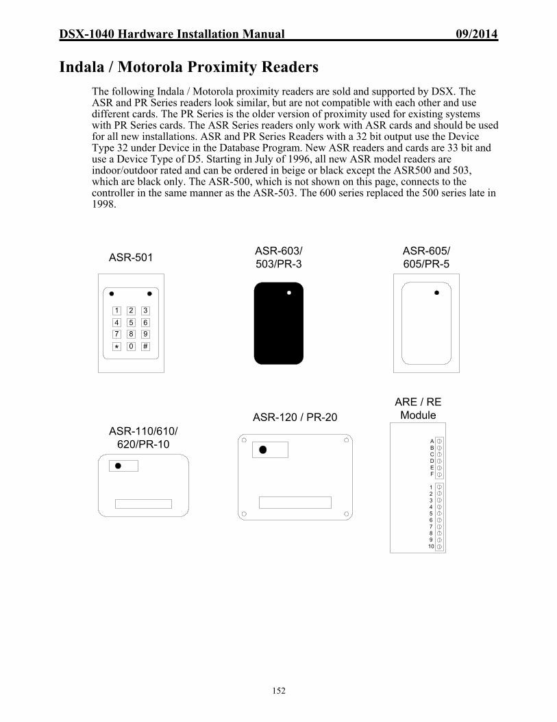
DSX-1040 Hardware Installation Manual 09/2014
152
Indala / Motorola Proximity Readers
The following Indala / Motorola proximity readers are sold and supported by DSX. The ASR and PR Series readers look similar, but are not compatible with each other and use different cards. The PR Series is the older version of proximity used for existing systems with PR Series cards. The ASR Series readers only work with ASR cards and should be used for all new installations. ASR and PR Series Readers with a 32 bit output use the Device Type 32 under Device in the Database Program. New ASR readers and cards are 33 bit and use a Device Type of D5. Starting in July of 1996, all new ASR model readers are indoor/outdoor rated and can be ordered in beige or black except the ASR500 and 503, which are black only. The ASR-500, which is not shown on this page, connects to the controller in the same manner as the ASR-503. The 600 series replaced the 500 series late in 1998.
ASR-501
321
4 5 6
987
* 0 #
ASR-603/503/PR-3
ASR-605/605/PR-5
ASR-120 / PR-20
12345678910
ABCDEF
ARE / REModule
ASR-110/610/620/PR-10

DSX-1040 Hardware Installation Manual 09/2014
153
Description
Indala Proximity Readers provide a Wiegand style of data interface to the DSX system. The proximity readers provide a single multi-color LED that is used to display the door status and an optional beeper.
LED Operation
Red = Door is Secure (Locked) Green = Door is Open (Unlocked) 1 Short Beep = Access Granted Amber Flashing & Beeping = Reader is in Lockout Mode. Two Beeps = Access Denied
Lockout Mode
Lockout occurs when the number of consecutive denials allowed at a reader has been exceeded. The reader will remain in the lockout mode for 30 seconds. During the Lockout the reader LEDs should switch rapidly from red to green for 30 seconds and it will not read ANY cards whatsoever. The number of consecutive denials allowed at a reader is determined under Location in the Database portion of the WinDSX software.
Access Denied If an Access Denied indicator is desired at the reader, a jumper must be placed between LED 2 and LED 3 of the DSX-1042 controller. LED 3 provides 2 quick pulses when a card is denied access. By placing a jumper between LED 2 and 3, the card reader LED will give two Green to Red flashes when a card is denied access. For an audible access denied indicator connect the Blue wire to the Pre-Warn terminals for 2 short beeps indicating access denied.
Unitized Readers
The ASR-500, 503, 505, 110, 112, 603, 605, 610, 620, PR-10, and PR-12 are self contained readers with the reader head and processing unit together in the same housing. The first of the following schematics is for the Unitized Readers that connect directly to the DSX-1042.
Readers with Electronics Module
All Indala readers not mentioned above provide a separate read head that sends information back to the remote electronics module where the data processing unit is housed. The remote electronics module may be located up to 50 feet from the read head and up to 500 feet from the DSX-1042 panel. The second schematic is for all Indala readers that require the use of a remote electronics module to interface the reader to the DSX-1042.
Presenting or using a Proximity Card
Proximity Cards should be presented to the read head with the body of the card parallel to the read head. The card should be held steady and not waved at the reader. Cards can be read through a purse or wallet that does not have metal between the card and the reader. To test the read range of a proximity reader, the card should be placed in front of the reader and then removed from the read area until it is successfully read. Do not hold the card in the read area and move it toward the reader, since pushing the card slowly toward the reader will not accurately reflect the read range.
Mounting
Proximity readers may be recessed 1 to 2 inches behind any non-conductive material. Effective read ranges will be reduced when readers are recessed behind a wall.

DSX-1040 Hardware Installation Manual 09/2014
154
ASR-500, 501, 503, 505, 110, 112, 603, 605, 610, PR10, and PR-12 Connected to a DSX-1042
DSX and Motorola now offer the ASR-501-8 which can provide a Card + PIN scenario or ASR-501-26 for a Card or PIN scenario. These formats require connection to only one DSX reader port or Device. Use caution when ordering due to the model being specific to operation. Card Plus PIN: The ASR-501-8 will require “Enable Card + PIN Operation” being enabled and “Number of digits in PIN Code” in the Location settings as well as a time zone being assigned to the “Keypad TZ” of the Device and PIN numbers assigned to the cardholders that must access the controlled door. The ASR-501-8 reader will require a card read during the active portion of the TZ set at the Reader TZ and would require a 4-7 digit code to be entered after the card read. Card Or PIN: The ASR-501-26 only requires that the code number entered at the keypad section be within the range of 1-65,535 and that number be set as a “Code #” for the cardholder. With this model the cardholders card is presented to the Cardreader or the cardholders “Code #” is entered at the Keypad for a Card or PIN style of operation. Card or PIN provides that either the Card or the Card Number (PIN) be provided to grant access. Separate Green LED Control
The Orange wire is used for separate Green LED control from LED 2.
Sounder Control The Blue wire is used for an optional Sounder connected to LED 3 or the Pre-Warn output.
Note /// The PR-Series Readers do not have two LED Control lines. Use the Brown wire to connect to LED 1 or 2. Device Types
Older Indala proximity readers purchased from DSX will use a Device Type of 32. Newer Indala proximity readers purchased from DSX will use a Device Type of D5. If the readers are from an existing system, a different device type may be used. Reference the (F1) Help screen for Device Types under Device in the Database Program. If there are difficulties determining the device type, contact DSX Technical Support for assistance.
11 12 13 14 15 16 17
1042 Side A
1 3 42 5 6 7 8 9 10 11 12 13 14 15 16 17 18 19 20 21 22
GNDTX RXSLAVE
TX RXMAS
COMMUNICATIONS
NC C NO
A-2OUTPUT A-1
SIDE A OUTPUTS
LED1 LED3 D1LED2 D0 GND
+12VDCPRE
SIDE A READER PORT SIDE A INPUTS
INP5INP6
INP7INP8
COM
BLA
CK
RE
D
BR
OW
N
OR
AN
GE
GR
EE
N
WH
ITE
SHIELD

DSX-1040 Hardware Installation Manual 09/2014
155
ASR-620+ PowerProx Readers Connected to a DSX-1042
ASR-620+ PowerProx Wiring Distance Chart
PowerProx The PowerProx connects to the controller as shown but requires a separate 12V or 24V linear power supply with common ground, further setup, adjustments and tuning. Please see the manual that comes with the reader for more information.
Separate Green LED Control
The Orange wire is used for separate Green LED control from LED output # 2.
Sounder Control The Blue wire is used for an optional Sounder connected to LED 3 or the Pre-Warn output.
Device Types If this is a Prox Reader with a 26 or 33 bit DSX format the Device Type would be D5. If this is a PR-10 with the AT&T format the Device Type would be “F9”. Reference the (F1) Help screen for Device Types under Device in the Database Program. If there are difficulties determining the device type, contact DSX Technical Support for assistance.
Cable Size Max Length
22awg 500'
18awg 500'
6 or 8 conductor w/shield
CT-620 to Controller Cable Length
18"
Power Supply to CT-620
2 conductor
Max LengthCable Size Max Length 12v Max Length 24v
24awg 20' 30'
22 awg 30' 44'
18 awg 80' 120'
3 or 4 conductor w/shield
ASR-620+ to CT-620 Cable Length
OR
AN
GE
BLA
CK
RE
D
BR
OW
N
GR
EE
N
WH
ITE
ASR 620 +
BLU
ESHIELD
11 12 13 14 15 16 17
1042 Side A
1 3 42 5 6 7 8 9 10 11 12 13 14 15 16 17 18 19 20 21 22
GNDTX RXSLAVE
TX RXMAS
COMMUNICATIONS
NC C NO
A-2OUTPUT A-1
SIDE A OUTPUTS
LED1 LED3 D1LED2 D0 GND
+12VDCPRE
SIDE A READER PORT SIDE A INPUTS
INP5INP6
INP7INP8
COM
CT
620
BL
AC
K
GR
EE
NB
RO
WN
OR
AN
GE
RE
D
BL
UE
WH
ITE
SH
IELD
BLACKRED
ORANGE
GREENWHITE
SHIELD
BROWN
BLUE
BLACKRED
ORANGE
GREENWHITE
SHIELD
BROWN
BLUE
The CT-620 Module includes a 1.6A fuse
(Littlefuse P/N 23501.6). The reader will not function if the
fuse is blown.The Buzzer (Blue
Wire) cannot be used when an ASR-620+ is connected to a 1020 OR 1021 Controller
FUSE HOLDER
Adding the Reader Power Source requires the Power Source and
Panel to have a common ground.
Linear Power Source,12-24vdc (= or less than 28vdc)
-+

DSX-1040 Hardware Installation Manual 09/2014
156
ASR-500/600 Series Readers with DS-12 / 8 bit Wiegand Keypad Connected to DSX-1042
Separate Green LED Control
The Orange wire is used for separate Green LED control from LED output # 2.
Sounder Control The Blue wire is used for an optional Sounder connected to LED 3 or the Pre-Warn output.
Note /// The PR-Series Readers do not have two LED Control lines. Use the Brown wire to connect to LED 1 or 2.
Device Types
If this is a Prox Reader with a 26 or 33 bit DSX format the Device Type would be D5. If this is a PR-10 with the AT&T format the Device Type would be “F9”. Reference the (F1) Help screen for Device Types under Device in the Database Program. If there are difficulties determining the device type, contact DSX Technical Support for assistance.
OR
AN
GE
BLA
CK
RE
D
BR
OW
N
GR
EE
N
WH
ITE
SHIELD
ISOLATE ANY UNUSED (N/C OR NO
CONNECTION) WIRES FROM OTHERS.
BR
OW
N
BLA
CK
RE
D
GR
EE
N
WH
ITE
SHIELD
TA
N
OR
AN
GE
N/C
N/C
1716151412
1 2 3
4 5 6
7 8 9
* 0 #
11 12 13 14 15 16 17
1042 Side A
1 3 42 5 6 7 8 9 10 11 12 13 14 15 16 17 18 19 20 21 22
GNDTX RXSLAVE
TX RXMAS
COMMUNICATIONS
NC C NO
A-2OUTPUT A-1
SIDE A OUTPUTS
LED1 LED3 D1LED2 D0 GND
+12VDCPRE
SIDE A READER PORT SIDE A INPUTS
INP5INP6
INP7INP8
COM

DSX-1040 Hardware Installation Manual 09/2014
157
Mercury MR-10/20 Magnetic Stripe Reader
The MR-10 is an indoor/outdoor magnetic stripe reader used to read existing customer cards or cards the customer is encoding. The MR-20 is identical to the MR-10 but also has an integral keypad for Card Plus PIN applications. Both units will mount on a door mullion or can be mounted to a single gang electrical box with the use of a trim plate. The MR-10 and MR-20 Magnetic Stripe Readers will work with a large number of existing magnetic stripe card formats. Many different Device Types under Device in the Database Program will allow these readers to work with existing cards. For DSX to assist, it may be necessary for a sample of 5 cards to be sent to DSX for evaluation. MR-10 MR-20
0 1
2 3
4 5
6 7
8 9
* #

DSX-1040 Hardware Installation Manual 09/2014
158
MR-10 Card Reader Description
The MR-10 Magnetic Stripe Reader is primarily used in conjunction with existing magnetic stripe cards. The MR-10 provides a Clock and Data style interface to the DSX-1042. The MR-10 incorporates two LED’s (Red and Green) that are used to display the following:
Card Reader LED Operation
Red = Door is Secure (Locked) Green = Door is Open (Unlocked) Red & Green Flashing = Reader is in Lockout Mode. Two Green and Red Flashes = Access Denied
MR-20 Card Reader Description
The MR-20 is the same as the MR-10 with the addition of an integral keypad. The MR-20 is the same in every way with the exception of the keypad. The Green and Red LED are used to indicate the following.
Card Reader Keypad LED Operation
Red = Door is Secure (locked) Green = Door is Open (Unlocked) Green to Red Flashing slow = Enter Pin Two Green to Red fast Flashes = Access Denied Green to Red Flashing fast = Reader is in Lockout Mode
Lockout Mode
Lockout occurs when the number of consecutive denials allowed at a reader has been exceeded. The reader will remain in the lockout mode for 30 seconds. During the Lockout the reader LEDs should switch rapidly from red to green for 30 seconds and it will not read ANY cards whatsoever. The number of consecutive denials allowed at a reader is determined under Location in the Database portion of the WinDSX software.
Access Denied If an Access Denied indicator is desired at the reader, a jumper may be placed between LED 2 and 3 of the DSX-1042 panel. LED 3 provides 2 quick pulses when a card is denied access. By placing a jumper between LED outputs 2 and 3, the card reader LED will give two green and red flashes when a card is denied access.
Special Wiring Information
LED Pull-up Resistor: Connect a 1K resistor between LED 2 and 5VDC. By placing the resistor between the 5VDC power and the LED wire, the Red LED will be On when the door is locked and the Green LED will be On when the door is unlocked. When the reader is used in the clock and data mode, which is typical for existing card applications, connect the Green wire of the reader to the terminal labeled White. Also connect the White wire from the reader to the terminal labeled Green on the silkscreen of the panel.
Reader Switch Settings
Reader Output MR Switch Setting Device TypeWiegand 1, 2, 3 Off / 4 On Wiegand (WE)Clock & Data 1,2 Off / 3, 4 On Clock/Data (A5 for DSX cards) Northern NR1 32 bit 1, 2, 3, 4 On CO, D4Northern NR1 26 bit 1, 4 On / 2, 3 Off WE

DSX-1040 Hardware Installation Manual 09/2014
159
MR-10 and MR-20 in Clock and Data Mode Connected to a DSX-1042
For Wiegand Output
Connect Green and White wires according to panel markings instead of drawing.
Connections The MR-20 connects in the same manner as the MR-10. When in the Clock and Data Mode the Data Lines for the MR-10 and MR-20 readers connect to the opposite colors that are marked on the face of the DSX-1042 Controller (green to white, white to green). The panel markings are for a Wiegand hook-up. This diagram is for the MR-10 and MR-20 when used in a Clock and Data Format.
Device Types
The proper clock and data device type can be found in the F1 Help screen for Device Type under Device in the Database program. If the proper device type cannot be determined, it may be necessary to send a sample of 5 cards to DSX for evaluation.
Sounder
The Orange wire may be used for the optional sounder and connects to LED 3 by itself or to the pre-warn output. If connected to LED 3 (terminal 13) the brown wire shown connected to terminals 12 & 13 would be connected to terminal 12 only with no connection to 13.
BR
OW
N
BLA
CK
RE
D
WH
ITE
GR
EE
N
SHIELD
1000 Ohm 1/4 WattResistor
TO 1040CDM #16 FOR 5VDC
12
0 1
2 3
4 5
6 7
8 9
* #
12 13 14 15 16 17
1042 Side A
1 3 42 5 6 7 8 9 10 11 12 13 14 15 16 17 18 19 20 21 22
GNDTX RXSLAVE
TX RXMAS
COMMUNICATIONS
NC C NO
A-2OUTPUT A-1
SIDE A OUTPUTS
LED1 LED3 D1LED2 D0 GND
+12VDCPRE
SIDE A READER PORT SIDE A INPUTS
INP5INP6
INP7INP8
COM

DSX-1040 Hardware Installation Manual 09/2014
160
Northern NR5 Magnetic Stripe Reader
The following is a wiring diagram for the Northern NR5 Magnetic Stripe Reader connected to DSX 1042 Controller. This reader is not sold by DSX but is compatible. The wiring information is accurate when this document was published but is subject to change. It should be noted that DSX does not sell or support this reader.
Lockout Mode
Lockout occurs when the number of consecutive denials allowed at a reader has been exceeded. The reader will remain in the lockout mode for 30 seconds. During the Lockout the reader LEDs should switch rapidly from red to green for 30 seconds and it will not read ANY cards whatsoever. The number of consecutive denials allowed at a reader is determined under Location in the Database portion of the WinDSX software.
Device Types
The proper clock and data device type can be found in the F1 Help screen for Device Type under Device in the Database program. If the proper device type cannot be determined, it may be necessary to send a sample of 5 cards to DSX for evaluation.
11 14 15 16
1042 Side A
1 3 42 5 6 7 8 9 10 11 12 13 14 15 16 17 18 19 20 21 22
GNDTX RXSLAVE
TX RXMAS
COMMUNICATIONS
NC C NO
A-2OUTPUT A-1
SIDE A OUTPUTS
LED1 LED3 D1LED2 D0 GND
+12VDCPRE
SIDE A READER PORT SIDE A INPUTS
INP5INP6
INP7INP8
COM
BR
OW
N
BLA
CK
WH
ITE
GR
EE
N
SHIELD
BLUE
Northern Computers Model 5IN2B - ISS2, (NR5)
MRSensors LTDCardiFFCF43AT
TO 1040CDM #16 FOR 5VDC
RED

DSX-1040 Hardware Installation Manual 09/2014
161
Readykey/PAC and Easikey Description
Readykey, PAC and Easikey proximity readers are connected to DSX controllers with the use of a DSX-RKM module. These readers are used to read both Readykey and PAC cards and tags. The DSX-RKM module supports two readers thus only one module is required per panel.
The RKM module includes a pair of jumpers near the 4 position terminal blocks that connect to the readers. The circuit board of the RKM is labeled near the jumpers with RK near 2 posts and EK near the 2 other posts. If connecting a Readykey or PAC reader to the RKM module, connect the jumper to the RK area. If connecting to an Easikey reader, connect the jumper to the EK area. The Readers use a four-wire cable for connection. Two conductors are for 12V power, one for LED, and one for data. The readers transmit the card data in ASCII. The RKM module converts the data and transmits it to the controller in a Wiegand format. The tags must be presented to the reader and the number (up to 10 digits) shown on the DSX monitor screen is the number used in the system. The readers have a green LED that can be controlled by the DSX panel. The LED when connected to LED output 1 will be on (Green) when the door is unlocked and off when the door is locked.
Readykey / PAC Easikey

DSX-1040 Hardware Installation Manual 09/2014
162
Readykey/PAC or Easikey Proximity Readers and RKM Connected to DSX-1042
Device Types
Readykey/PAC and Easikey Proximity Readers use a Device Type of H3. The cards and keys must be presented to the reader and the number displayed is the number entered into the system.
LED
2A
GN
D
+1
2V
D0
A
D1
A
+12V & GND from either A or B side of 1042
CONNECT JUMPER ON RKM MODULE TO:RK FOR READYKEY OR EK FOR EASIKEY READERS.
READER SIDE A
VCA
V+ SIG
V-
READER SIDE B
VCA
V+ SIG
V-
GN
D+
12V
D1
BD
0B
LED
2B
D1
AD
0A
LED
2A
V-
V+
SIG
VC
A
V+V-
SIG
VC
ARKM Module
RK EK RK EK
TO SIDE B
12 13 14 15 16 17
1042 Side A
1 3 42 5 6 7 8 9 10 11 12 13 14 15 16 17 18 19 20 21 22
GNDTX RXSLAVE
TX RXMAS
COMMUNICATIONS
NC C NO
A-2OUTPUT A-1
SIDE A OUTPUTS
LED1 LED3 D1LED2 D0 GND
+12VDCPRE
SIDE A READER PORT SIDE A INPUTS
INP5INP6
INP7INP8
COM
5.1 ohm5 watt
Use provided 5.1 ohm, 5 watt resistor as shown when 2 readers are powered from reader port.

DSX-1040 Hardware Installation Manual 09/2014
163
Securakey Barium Ferrite Readers
The Securakey SK-028, SK-034, and SK-038 are the Barium Ferrite Readers that DSX sells and supports. The SK-028 is the Rusco Barium Ferrite Replacement Reader. The SK-034 is the Securakey Card Reader that reads Securakey Cards. The SK-038 is the Cardkey Barium Ferrite Replacement Reader. The Securakey readers connect to the DSX panels directly. The PCSC reader requires interface hardware. The readers and interface should be tested to verify operation. It should be noted that DSX does not sell, support, or provide additional cards for the PCSC readers.
SK-028 / SK-034 / SK-038Securakey Reader

DSX-1040 Hardware Installation Manual 09/2014
164
Description
All Securakey Touch Plate Readers follow the same wiring scheme. There are currently 3 different Securakey Readers, the SK-028, 034, and 038. The SK-028 is used to read existing Rusco barium ferrite cards. The SK-034 is used to read Securakey barium ferrite cards. The SK-038 is used to read existing Cardkey barium ferrite cards. All 3 readers wire to the panel in the same manner and transmit the card data in a Wiegand format.
LED Operation
Red = Door is Secure (Locked) Red Off = Door is Open (Unlocked) Red Flashing = Reader is in Lockout Mode. Two to Red Flashes = Access Denied
Lockout Mode
Lockout occurs when the number of consecutive denials allowed at a reader has been exceeded. The reader will remain in the lockout mode for 30 seconds. During the Lockout the reader LEDs should switch rapidly from red to green for 30 seconds and it will not read ANY cards whatsoever. The number of consecutive denials allowed at a reader is determined under Location in the Database portion of the WinDSX software.
Access Denied If an Access Denied indicator is desired at the reader, a jumper may be placed between LED 2 and LED 3 of the DSX-1042 panel. LED 3 provides 2 quick pulses when a card is denied access. By placing a jumper between LED outputs 2 and 3, the card reader LED will give two Green to Red flashes when a card is denied access.
Retrofits
The SK-028 Rusco compatible reader provides a replacement for the Rusco barium ferrite reader. It will connect directly to the DSX-1042 panel and read the existing Rusco Cards.
The SK-038 is used in a DSX system to read Cardkey barium ferrite cards. The Cardkey barium ferrite insert reader can be used with the DSX system if the Cardkey insert reader Wiegand interface and the DSX-CKI module are both used. Otherwise the SK-038 must be used to read the Cardkey Barium Ferrite Cards and is connected directly to the DSX-1042 Panel.
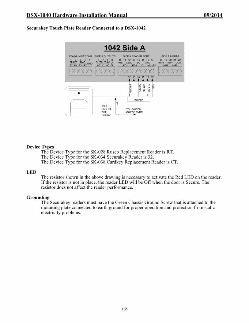
DSX-1040 Hardware Installation Manual 09/2014
165
Securakey Touch Plate Reader Connected to a DSX-1042
Device Types
The Device Type for the SK-028 Rusco Replacement Reader is RT. The Device Type for the SK-034 Securakey Reader is 32. The Device Type for the SK-038 Cardkey Replacement Reader is CT.
LED
The resistor shown in the above drawing is necessary to activate the Red LED on the reader. If the resistor is not in place, the reader LED will be Off when the door is Secure. The resistor does not affect the reader performance.
Grounding
The Securakey readers must have the Green Chassis Ground Screw that is attached to the mounting plate connected to earth ground for proper operation and protection from static electricity problems.
12 13 14 15 16 17
1042 Side A
1 3 42 5 6 7 8 9 10 11 12 13 14 15 16 17 18 19 20 21 22
GNDTX RXSLAVE
TX RXMAS
COMMUNICATIONS
NC C NO
A-2OUTPUT A-1
SIDE A OUTPUTS
LED1 LED3 D1LED2 D0 GND
+12VDCPRE
SIDE A READER PORT SIDE A INPUTS
INP5INP6
INP7INP8
COM
BR
OW
N
BLA
CK
RE
D
GR
EE
N
WH
ITE
SHIELD
1000 Ohm 1/4 WattResistor
TO 1040CDM #16 FOR 5VDC
12

DSX-1040 Hardware Installation Manual 09/2014
166
Time Keeping Systems TKS-110 Bar Code Reader Below is one of the bar code readers that will work with the DSX System. The TKS-110 is the bar code reader that DSX sells and supports. The TKS-110 will read almost any existing bar code including Kronos. Search the Help Screen (F1) for Device Types under Device in the Database Program to determine the proper device type for the Bar Code you desire to use. It is recommended to use 18 AWG wire with this reader since it is 5V powered and voltage drop can be critical to proper operation. If necessary, use a 12V regulator at the reader. Connect the 12V power of the panel to the regulator and the 5V output of the regulator to the reader. This will keep the 5V power constant and compensate for a long wire run. Note /// New TKS-110 Readers that are smaller than the original and are potted and sealed are 12V powered. There is also an adapter plate that will allow a new unit to mount in the place of the older, larger reader and to a single gang electrical box.
TKS-110

DSX-1040 Hardware Installation Manual 09/2014
167
Description
TKS-110 Bar Code readers will connect directly to the DSX-1042 panel and will work with both new and existing bar code access cards. The reader is compatible with the following bar code symbologies: Code 39, Interleaved 2 of 5, UPC/EAN, Codabar, Code 93, Code 11, Code 128, and MSI. The TKS-110 is auto-discriminating and reads in both directions.
LED Operation
Red On = Door is Secure (Locked) Green On = Door is Open (Unlocked) Red/Green Flashing = Reader is in Lockout Mode. Red /Green Flashing twice = Access Denied
Lockout Mode
Lockout occurs when the number of consecutive denials allowed at a reader has been exceeded. The reader will remain in the lockout mode for 30 seconds. During the Lockout the reader LEDs should switch rapidly from red to green for 30 seconds and it will not read ANY cards whatsoever. The number of consecutive denials allowed at a reader is determined under Location in the Database portion of the WinDSX software.
Access Denied If an Access Denied indicator is desired at the reader, a jumper may be placed between LEDs 2 and 3 of the DSX-1042 panel. LED 3 provides 2 quick pulses when a card is denied access. By placing a jumper between LED outputs 2 and 3, the card reader LED will give two Red to Green flashes when a card is denied access.
IC-201 Pre-Printed Bar Code Labels
When using the IC-201 Pre-printed bar code labels with the TKS-110 the reader must be set in the Wiegand output mode. To do this, do not connect the Orange, Blue, or Yellow wires. The Device Type to use with the TKS-110 in the Wiegand mode and the IC-201 Bar Codes is WE.
Bar Code Positioning The Bar Code should be located on the card according to the specifications below.

DSX-1040 Hardware Installation Manual 09/2014
168
TKS-110 Bar Code Reader in Clock and Data Mode to a DSX-1042
Wiegand Mode
To put the TKS-110 in a Wiegand Output Mode, Do Not connect the Yellow, Orange or Blue wires. Isolate these wires individually. For proper 26 bit Wiegand mode the barcode must be formatted with a 3 digit facility code and a 5 digit card number that is 65534 and lower in range.
Device Types
The above diagram shows the proper connection for the TKS-110 bar code reader when used in the Clock and Data mode. The device type used for this reader will vary depending on the card it is being used with. If you wish to use this reader with an existing card base, please contact DSX for compatibility testing and proper Device Type selection.
1042 Side A
1 3 42 5 6 7 8 9 10 11 12 13 14 15 16 17 18 19 20 21 22
GNDTX RXSLAVE
TX RXMAS
COMMUNICATIONS
NC C NO
A-2OUTPUT A-1
SIDE A OUTPUTS
LED1 LED3 D1LED2 D0 GND
+12VDCPRE
SIDE A READER PORT SIDE A INPUTS
INP5INP6
INP7INP8
COM
12 13 15 1614
Isolate any unused
(NC) wires from others.
BR
OW
N
BLA
CK
SHIELD
YE
LLO
W
VIO
LE
T
GR
EE
N
BLU
EN
C
OR
AN
GE
NC
NOTE /// TKS MADE AN ALUMINUM UNIT THAT MEASURED 6"X2" THAT REQUIRES 5VDC. TKS NOW MAKES AN ALL PLASTIC
UNIT THAT MEASURES 5"X1.5" THAT REQUIRES 12VDC.
RED TO +VDC, SEE NOTES BELOW

DSX-1040 Hardware Installation Manual 09/2014
169
TKS-110 / DS-12-8C Keypad in Clock and Data Mode Connected to a DSX-1042
Power The Keypad is 5/12V and the reader is 5V. Voltage drop and wire length and gauge must be considered. It may be necessary to use a 12V feed for the Keypad and on this 12V feed connect a 12 to 5V regulator. The 5V output of the regulator powers the card reader.
Device Types
This diagram shows the connection of the bar code reader and a keypad for a Card + PIN mode of operation. The card would be swiped and then the PIN entered into the keypad. The above diagram shows the proper connection for the TKS-110 bar code reader and the DS-12-8C Keypad both of which have a clock and data output. The device type used for this reader will vary depending on the card it is being used with. If you wish to use this reader with an existing card base, please contact DSX for compatibility testing and proper Device Type selection.
1042 Side A
1 3 42 5 6 7 8 9 10 11 12 13 14 15 16 17 18 19 20 21 22
GNDTX RXSLAVE
TX RXMAS
COMMUNICATIONS
NC C NO
A-2OUTPUT A-1
SIDE A OUTPUTS
LED1 LED3 D1LED2 D0 GND
+12VDCPRE
SIDE A READER PORT SIDE A INPUTS
INP5INP6
INP7INP8
COM
12 13 14 15 16
Isolate any unused
(NC) wires from others.
BR
OW
N
BLA
CK
GR
EE
N
VIO
LE
TSHIELD
YE
LLO
W
BR
OW
N
BLA
CK
RE
D
GR
EE
N
WH
ITE
SHIELD
DIODES
BLU
EN
C
OR
AN
GE
NC
1716151412
1 2 3
4 5 6
7 8 9
* 0 #
NOTE /// TKS MADE AN ALUMINUM UNIT THAT MEASURED 6"X2" THAT REQUIRES 5VDC. TKS NOW MAKES AN ALL PLASTIC UNIT THAT MEASURES 5"X1.5" THAT REQUIRES 12VDC.
RED TO +VDC, SEE NOTES BELOW
RE
D
OR
AN
GE
NC
PIN
KN
C
TA
NN
C
BLU
EN
C

DSX-1040 Hardware Installation Manual 09/2014
170
TKS-110 in ASCII Mode Connected to a DSX-1042
Device Types
The above diagram shows the proper connection for the TKS-110 bar code reader when used in the ASCII output mode. The device type used for this reader will vary depending on the card it is being used with. If you wish to use this reader with an existing card base, please contact DSX for compatibility testing and proper Device Type selection. The transistor signal inverter is available from DSX.
1042 Side A
1 3 42 5 6 7 8 9 10 11 12 13 14 15 16 17 18 19 20 21 22
GNDTX RXSLAVE
TX RXMAS
COMMUNICATIONS
NC C NO
A-2OUTPUT A-1
SIDE A OUTPUTS
LED1 LED3 D1LED2 D0 GND
+12VDCPRE
SIDE A READER PORT SIDE A INPUTS
INP5INP6
INP7INP8
COM
12 13 15 16
Isolate any unused
(NC) wires from others.
BaseEmitter
Collector
2N2222 NPN Transistor
BR
OW
N
BLA
CK
SHIELD
BLU
EN
C
YE
LLO
WN
C
VIO
LE
TN
C
YE
LLO
W
OR
AN
GE
WHITE
BLACK
GR
EE
N
15
16
RED TO +VDC, SEE NOTES BELOW
RE
D
NOTE /// TKS MADE AN ALUMINUM UNIT THAT MEASURED 6"X2" THAT REQUIRES 5VDC. TKS NOW MAKES AN ALL PLASTIC UNIT THAT MEASURES
5"X1.5" THAT REQUIRES 12VDC.

DSX-1040 Hardware Installation Manual 09/2014
171
XceedID Readers and Keypads
There are eight different models of XceedID available from DSX. All XceedID readers follow a similar wiring scheme. Each reader or keypad is shipped with documentation. If further documentation is required please visit www.xceedid.com or call 303-273-9930.
XF1500
XF1560 XF2110
1 2 3
4 5 6
7 8 9
* 0 #
XF1100
XF1060
XF1050
XF2100

DSX-1040 Hardware Installation Manual 09/2014
172
Description
XceedID Proximity Readers provide a Wiegand style of data interface to the DSX system. The proximity readers provide a single multi-color LED that is used to display the door status and an optional beeper.
LED Operation
Red = Door is Secure (Locked) Green = Door is Open (Unlocked) Red/Green Flashing = Reader is in Lockout Mode. Red /Green Flashing twice = Access Denied
Lockout Mode
Lockout occurs when the number of consecutive denials allowed at a reader has been exceeded. The reader will remain in the lockout mode for 30 seconds. During the Lockout the reader LEDs should switch rapidly from red to green for 30 seconds and it will not read ANY cards whatsoever. The number of consecutive denials allowed at a reader is determined under Location in the Database portion of the WinDSX software.
Sounder Control
The Yellow wire is used in most XceedID readers for an optional Sounder when connected to the Pre-Warn output. The Blue wire is used in the XceedID 1050 and 1060 readers for the Sounder.
Presenting or using a Proximity Card Proximity Cards should be presented to the read head with the body of the card parallel to the read head. The card should be held steady and not waved at the reader. Cards can be read through a purse or wallet that does not have metal between the card and the reader. To test the read range of a proximity reader, the card should be placed in front of the reader and then removed from the read area until it is successfully read. Do not hold the card in the read area and move it toward the reader, since pushing the card slowly toward the reader will not accurately reflect the read range.

DSX-1040 Hardware Installation Manual 09/2014
173
XceedID Customer Application Note KF26 Setting XceedID XF2110 Keypad to 26 Bit Output How to Configure XF2110 Keypad to Output 26 Bits and a Fixed Facility Code. Step1: Power cycle the reader to initialize the reader and enter the following code on the keypad within the 1st minute of initialization: * 8 8 8 8 9 9 9 9 The led turns green and a short triple-beep indicates that the reader is ready to have the keypad format entered on the keypad. Step2: Within 5 seconds enter # followed by the fixed facility code from the keypad. The facility code must be a 3 digit decimal number between 000 and 255. Facility code examples: Enter # 0 9 6 for fixed facility code 96 Enter # 1 2 8 for fixed facility code 128 A triple beep/green led flash will indicate a successful configuration of the keypad. Step3: To use the keypad in this mode enter your Code and press #. The reader sends the Code (packaged as a 26-bit Wiegand output along with the fixed facility code). The Code must be a number between 1 and 65535. RESET Back to Factory Default: In order to set the reader in ‘8-bit burst keypad mode (default) follow these 2 steps: Step1: Power cycle the reader to initialize the reader and enter the following code on the keypad within the 1st minute of initialization: * 8 8 8 8 9 9 9 9 Step2 : You have 5 seconds to enter the keypad format on the keypad: Enter * 0. A triple beep/green led flash will indicate a successful configuration of the keypad. In this mode the keypad sends an 8-bit burst to the panel for every key press NOTE /// For specific purpose and setup descriptions regarding 26-bit and 8-bit operations refer to the “Card Plus PIN / Card Or PIN section of this manual.

DSX-1040 Hardware Installation Manual 09/2014
174
XceedID Proximity Reader Connected to a DSX-1042
Device Types The proper clock and data device type can be found in the F1 Help screen for Device Type under Device in the Database program. If the proper device type cannot be determined, it may be necessary to send a sample of 5 cards to DSX for evaluation.
10 11 12 13 14 15 16 17
1042 Side A
1 3 42 5 6 7 8 9 10 11 12 13 14 15 16 17 18 19 20 21 22
GNDTX RXSLAVE
TX RXMAS
COMMUNICATIONS
NC C NO
A-2OUTPUT A-1
SIDE A OUTPUTS
LED1 LED3 D1LED2 D0 GND
+12VDCPRE
SIDE A READER PORT SIDE A INPUTS
INP5INP6
INP7INP8
COM
OR
AN
GE
BL
AC
K
RE
D
BR
OW
N
GR
EE
N
WH
ITE
SHIELD
YE
LLO
W
PIN
K
VIO
LET
NC
NC
Isolate any unused (NC) wires from others
and from Ground.
GR
AY
NC
PU
RP
LE
NC
TA
NN
C
USE BLUE IF ON XF1050 or XF1060
INSTEAD OF YELLOW
Initial power up of reader will provide 6 “Bad Card Read ###” messages, this is normal.

DSX-1040 Hardware Installation Manual 09/2014
175
DSX Keypads Note /// HID and Motorola now offer Reader/Keypad combinations which can provide a Card + PIN scenario or a Card or PIN scenario. These formats require a single gang electrical box for mounting along with connection to only one DSX reader port or Device. Check the HID 5355 section or the Motorola ASR-501 section for more information. Use caution when ordering due to the model being specific to operation.
The DS-12 Keypad is available in several varieties and each has specific compatibilities. Use caution when ordering to ensure a correct purchase. Keypads may be used as either a primary mechanism to enter a code number for door access or as the secondary method of using a card and a PIN for entry. With the PIN options turned on in WinDSX, a valid card must be presented to a card reader followed by the entry of a 4 to 7 digit PIN for access. Other options can direct WinDSX to allow duplicate PIN numbers to be allowed. In some cases the Reader and Keypad can connect to the same side of a DSX panel. In some cases a manufacturer has a product line that includes a reader/keypad combination that mounts to one single gang box. In other cases it requires two single gang boxes for the two pieces of hardware even though they may still connect to the same reader port. Use caution when connecting and reference this manual for additional connection drawings regarding known compatibilities. If you are unsure, call DSX Technical Support for assistance. The DS-12 is an Indoor/Outdoor keypad with a Stainless Steel finish. The older DS-12 has a BCD output that connects to the first four inputs on a DSX-1032 and is no longer supported. The new DS-12 has a Wiegand Burst Output that connects to the card reader port. The following diagrams show how to connect the DS-12 keypads to the DSX-1042.
Note /// The DS-12 keypads that have a BCD output, which can be identified by their data connection to inputs 1-4 on the controller, are no longer compatible with WinDSX Software. Those keypads must have the DS400IB – BCD to Wiegand 8 bit Burst Module added, to convert their output. The module can be placed at the controller.
DS-12 Indoor/Outdoor Keypad
1 2 3
4 5 6
7 8 9
* 0 #

DSX-1040 Hardware Installation Manual 09/2014
176
Description
The DS-12 Keypad is available in several varieties and each has specific compatibilities. Use caution when ordering to ensure a correct purchase. The DS-12 Keypad can provide all key information as a Wiegand Burst Output to the DSX-1042. This keypad may be used standalone or added to some readers for Card + PIN operation. Four, five, six, or 7 digit codes are possible with full range of all number sequences. The following pages may assist in proper purchase and configuration. Contact DSX Technical Support for additional assistance if needed.
LED Operation
Green Red On Off = Door is Open (Unlocked) Green Red Off On = Door is Secure (Locked) Green Red On On = Door is Secure (Locked) and keypad data entry is occurring. Green Red 2 Flashes On = Invalid code was entered, Door is Secure (Locked) Green Red Flash Flash = Keypad is in Lockout Mode.
The Green LED will turn on with the first key depression and turn off when the panel has recognized the proper number of digits for a PIN. If the PIN is 5 digits long, the Green LED would turn On when the first number is pressed and turn Off when the fifth number is pressed. With the same example, if only 4 digits are entered, the Green LED will turn Off 5 seconds after the last digit is pressed. When the Green LED is Off the PIN can be entered or re-entered. If the door is secure and the wrong code is entered will cause the Green LED to flash twice.
Lockout Mode
Lockout occurs when the number of consecutive denials allowed at a reader has been exceeded. The reader will remain in the lockout mode for 30 seconds. During the Lockout the reader LEDs should switch rapidly from red to green for 30 seconds and it will not accept ANY keypresses whatsoever. The number of consecutive denials allowed at a reader is determined under Location in the Database portion of the WinDSX software.
Power The DS-12 is 5 – 12 V powered. Jumper Pins on the back make the selection of 5 or 12V. With the jumper on one of the two pins the keypad is 12V. With the jumper on both pins the keypad is 5V.
26 bit Versions DS-12-26 & DS-12-SL26 (use for special applications only)
The DS-12 26 bit output keypad has a single LED control line (brown wire) which typically connects to LED # 2. This version of the DS-12 has a code limitation of 65534. Numbers higher than this will not work. This version can be added to some readers for Card or PIN operation. Once a code is entered you must press the #. This variety commonly uses Device Type 26, D5 or WE but may require a call to DSX Technical Support for proper settings.
ThinLine Keypad Illumination
The 2X6 thinline keypad, DS-12-SL, has two LED’s that can be used for illumination and draw an additional 20ma. To enable cut the wire jumper next to the wiring connector.

DSX-1040 Hardware Installation Manual 09/2014
177
DS-12 Keypad and PiezoProx Reader connected to a DSX-1042
Note /// A keypad of the correct format is required for “Card Plus” (-8) or “Card Or” (-26)
Operation. Note /// An order for the unit shown above requires 2 part numbers. A part number for the Reader
and a part number for the Keypad. Power
The DS-12 is 5 – 12 V powered. Jumper Pins on the back make the selection of 5 or 12V. With the jumper on one of the two pins the keypad and reader are both 12V. With the jumper on both pins the keypad and reader are 5V.
LED Control
The Brown wire connected to LED2 controls the Green and Red LEDs.
Device Types The PiezoProx Reader / Keypad is an indoor/outdoor reader / keypad combination with a single gang configuration and a Black finish. The Device Type for the PiezoProx is D5. If a 26bit keypad is used, the “#” key must be pressed after the code is entered at the keypad to send the data.
BLA
CK
RE
D
BR
OW
N
GR
EE
N
WH
ITE
SHIELD
12 14 15 16 17
1042 Side A
1 3 42 5 6 7 8 9 10 11 12 13 14 15 16 17 18 19 20 21 22
GNDTX RXSLAVE
TX RXMAS
COMMUNICATIONS
NC C NO
A-2OUTPUT A-1
SIDE A OUTPUTS
LED1 LED3 D1LED2 D0 GND
+12VDCPRE
SIDE A READER PORT SIDE A INPUTS
INP5INP6
INP7INP8
COM
OR
AN
GE
NC
PIN
KN
C
TA
NN
C
BLU
EN
C
Isolate any unused (N/C or No Connection)
wires from others.
YE
LLO
WN
C
Set Keypad voltage to 5V.Set Reader v. to 12V.
/// Add DS-12-8 Keypad to PiezoProx for Card Plus PIN./// Add DS-12-26 Keypad to PiezoProx for Card or PIN.
1 2 3
4 5 6
7 8 9
* 0 #
PiezoProx

DSX-1040 Hardware Installation Manual 09/2014
178
DS-12 Keypad with Wiegand Output Connected to a DSX-1042
Description
This keypad can be used standalone for or added to some readers for Card + PIN operation. The Wiegand Burst Output of the DS-12-8W has no code limitations and is usually a Device Type of DK.
Power The DS-12 is 5 – 12 V powered. Jumper Pins on the back make the selection of 5 or 12V. With the jumper on one of the two pins the keypad is 12V. With the jumper on both pins the keypad is 5V.
Aux. Output
The Blue wire is an open collector output that sinks 250 ma. It provides a 30-second negative when any key is pressed.
LED Control With the Orange wire not connected the brown wire controls the Green LED and the yellow wire controls the Red LED. When an LED line is pulled low the corresponding LED turns on. With the Orange wire connected to ground the Brown line controls both LEDS. When the Brown line is pulled low Green is on and Red is off. With the Brown line floating the Red LED is on and Green is off.
Device Types The DS-12 Keypad is an indoor/outdoor keypad with a single gang configuration and a Stainless Steel finish. The Device Type for the DS-12 with Wiegand output is DK. All Wiegand Burst Output Keypads use Device Type DK but could require a call to DSX for proper settings.
Isolate any unused (N/C or No Connection)
wires from others.
BLA
CK
RE
D
BR
OW
N
GR
EE
N
WH
ITE
SHIELD1 2 3
4 5 6
7 8 9
* 0 #
12 14 15 16 17
1042 Side A
1 3 42 5 6 7 8 9 10 11 12 13 14 15 16 17 18 19 20 21 22
GNDTX RXSLAVE
TX RXMAS
COMMUNICATIONS
NC C NO
A-2OUTPUT A-1
SIDE A OUTPUTS
LED1 LED3 D1LED2 D0 GND
+12VDCPRE
SIDE A READER PORT SIDE A INPUTS
INP5INP6
INP7INP8
COM
OR
AN
GE
NC
PIN
KN
C
TA
NN
C
BLU
EN
C

DSX-1040 Hardware Installation Manual 09/2014
179
DS-12 Keypad with Clock and Data Output Connected to a DSX-1042
Description
The DS-12-8C keypad is usually added to readers for Card + PIN operation. When connected in parallel with a barcode, magstripe or proximity reader to one reader port, the card reader must be wired in Clock & Data format (if available).
Power
The DS-12 is 5 – 12 V powered. Jumper Pins on the back make the selection of 5 or 12V. With the jumper on one of the two pins the keypad is 12V. With the jumper on both pins the keypad is 5V.
Device Types
The DS-12 Keypad is an indoor/outdoor keypad with a single gang configuration and a Stainless Steel finish. The Device Type for the DS-12 with Clock and Data Output varies depending on what card reader and card format it is to be used in conjunction with. This keypad is typically used in conjunction with the TKS-110 barcode reader or any magstripe reader with a clock and data output and is usually a Device Type of WE or D5 but could require a call to DSX for proper settings.
Isolate any unused (N/C or No Connection)
wires from others.
BLA
CK
RE
D
BR
OW
N
GR
EE
N
WH
ITE
SHIELD1 2 3
4 5 6
7 8 9
* 0 #
12 14 15 16 17
1042 Side A
1 3 42 5 6 7 8 9 10 11 12 13 14 15 16 17 18 19 20 21 22
GNDTX RXSLAVE
TX RXMAS
COMMUNICATIONS
NC C NO
A-2OUTPUT A-1
SIDE A OUTPUTS
LED1 LED3 D1LED2 D0 GND
+12VDCPRE
SIDE A READER PORT SIDE A INPUTS
INP5INP6
INP7INP8
COM
OR
AN
GE
NC
PIN
KN
C
TA
NN
C
BLU
EN
C

DSX-1040 Hardware Installation Manual 09/2014
180
Schlage Series III Scramble Keypad Connected to a DSX-1042 Front Side Back Side
Note /// This keypad can be used in keypad only or Card or PIN applications only. Common programming options include: Mode 0, 9 digit Code number, DSX Device Type – U6, Facility Code can be 1-256 Mode 3, 4 digit Code number (1-9999), DSX Device Type – WE, Facility Code 1-256 Mode 6, 5 digit Code number (1-65535), DSX Device Type – WE, Facility Code 1-256 Or 5 digit Code number (1-99999), DSX Device Type – D3, Facility Code 0 (zero) Mode 8, 7 digit Code number, DSX Device Type – DK Or 4-7 digit PIN for Card + PIN, Device Type depends on Card Format. Mode programming is achieved by setting the bottom rotary switche on the back of the keypad. Facility Code is set with the upper 2 Rotary Switches. Rotary switch programming is also available from the manufacturer of the keypad.
Manufacturers website - http://schlage.com Product Brochure - http://securitymanagementsystem.schlage.com/Readers.asp
CODEGUARD
12
34
56
78
910
1112
1314
1516
12F 12F
79A
0
43DE 5678
C
9AB
0
43DE 5678
C
9AB
04
1 2 3DEF
56
8
C B
10 11 12 13 14 15 16
1042 Side A
1 3 42 5 6 7 8 9 10 11 12 13 14 15 16 17 18 19 20 21 22
GNDTX RXSLAVE
TX RXMAS
COMMUNICATIONS
NC C NO
A-2OUTPUT A-1
SIDE A OUTPUTS
LED1 LED3 D1LED2 D0 GND
+12VDCPRE
SIDE A READER PORT SIDE A INPUTS
INP5INP6
INP7INP8
COM
17
OR
AN
GE
BL
AC
K
BR
OW
N
GR
EE
N
WH
ITE
YE
LLO
W
SHIELD
RE
D
0 0
0
12
34
56
78
91
01
11
21
31
41
51
6
BLACKRED
GREENYELLOWWHITEBROWN
ORANGE

DSX-1040 Hardware Installation Manual 09/2014
181
DS400 Interface Modules DSX-400IC - 3 x 4 to 8 bit Clock and Data Conversion Module to a DSX-1042
Application
The DSX-400IC 3 x 4 keypad matrix to 8 bit clock and data module can be used with a Cardkey D20 or other keypad to convert their 3 x 4 output to an 8 bit clock and data output. This could be used to add a keypad to any card reader that has a clock and data output to form a reader/keypad operation.
Device Types The proper device type is determined by the reader and cards used.
GR
EE
N
WH
ITE
BLA
CK
RE
D
3x4 Keypad
See included chart for
connection specifics
BLA
CK
RE
D
GR
EE
N
WH
ITE
BR
OW
NB
LUE
OR
AN
GEN
CBLACKRED
GREENWHITE
14 15 16
1042 Side A
1 3 42 5 6 7 8 9 10 11 12 13 14 15 16 17 18 19 20 21 22
GNDTX RXSLAVE
TX RXMAS
COMMUNICATIONS
NC C NO
A-2OUTPUT A-1
SIDE A OUTPUTS
LED1 LED3 D1LED2 D0 GND
+12VDCPRE
SIDE A READER PORT SIDE A INPUTS
INP5INP6
INP7INP8
COM
DS400-IC
12 vGND
RA 1
LED
Rev 5RA 0
17
Isolate any unused (N/C or No
Connection) wires from others.
NOTE /// Previous REVs of the DS400 may include flying leads.
NOTE /// REVs below 5 DS400 require 5VDC.
Isolate any unused (NC or No
Connection) wires from others.
SH
IEL
D
YE
LLO
WN
C

DSX-1040 Hardware Installation Manual 09/2014
182
DSX-400IB – 3 x 4 to 8 bit Wiegand Conversion Module to DSX-1042
Application The DSX-400IB 3 x 4 keypad matrix to 8 bit Wiegand module can be used with a Cardkey D20, D40 or other keypad to convert their 3 x 4 output to an 8 bit Wiegand output. This could be used to add a keypad to any card reader that has a Wiegand output to form a reader/keypad operation
Device Types
The proper device type is determined by the reader and cards used. DSX-400IB Chart of Connections
DSX-400IB W/
Terminals
DSX-400IB W/ Pigtail
Row and Col
DS-12 – 3 x 4
D20 / D40
HID Northern Keypad
HID5355-K09
P2
3 Orange Row 1 Brown Pin 1 Gray 1
7 Blue Col 1 Gray Pin 2 Tan 7
6 Brown Col 2 Violet Pin 3 White/Blue 6
8 White Row 4 Yellow Pin 4 Pink 4
1 Green Row 3 Green Pin 6 Red/Yellow 3
5 Red Col 3 Orange Pin 7 White/Green 5
2 Black Row 2 Blue Pin 9 Violet 2
14 15 16
1042 Side A
1 3 42 5 6 7 8 9 10 11 12 13 14 15 16 17 18 19 20 21 22
GNDTX RXSLAVE
TX RXMAS
COMMUNICATIONS
NC C NO
A-2OUTPUT A-1
SIDE A OUTPUTS
LED1 LED3 D1LED2 D0 GND
+12VDCPRE
SIDE A READER PORT SIDE A INPUTS
INP5INP6
INP7INP8
COM
GR
EE
N
WH
ITE
BLA
CK
RE
D
17
Isolate any unused (NC or No
Connection) wires from others.
3x4 Keypad
See included chart for
connection specifics R
ow
2
Co
lum
n 1
Ro
w 1
Ro
w 4
Co
lum
n 2
Co
lum
n 3
Ro
w 3
BLACKRED
GREENWHITE
DS400-IB
SH
IELD
20
NC12 v
GND
RA 0
RA 1LED
Rev 5
NOTE /// Previous REVs of the DS400 may include flying leads and connect differently.
NOTE /// REVs below 5 DS400 require 5VDC.
NOTE /// The REV 5 DS400-XX requires 12VDC12345678

DSX-1040 Hardware Installation Manual 09/2014
183
DSX-400ID – BCD to 8 bit Wiegand Conversion Module to DSX-1042
Application
The DSX-400ID BCD to Wiegand module is used to convert BCD keypads to a Wiegand 8 bit burst output that is compatible with the WinDSX software and firmware. This includes the BCD DS-12 – 5v and 12v keypad models.
Note /// The DS-12 keypads that have a BCD output which can be identified by their data connection to inputs 1-4 on the controller are no longer compatible with WinDSX Firmware and Software. Those keypads must have the DSX-400ID – BCD to Wiegand 8 bit burst module to convert their output. The module can be placed at the controller.
WH
ITE
BL
AC
K
RE
D
VIO
LET
SHIELD
1 2 34 5 67 8 9
* 0 #
BC
D 1
BC
D 2
BC
D 4
BC
D 8
WH
ITE
GR
EE
N
BL
AC
K
14 15 16
RE
D
11 12 13 16 17
1042 Side A
1 3 42 5 6 7 8 9 10 11 12 13 14 15 16 17 18 19 20 21 22
GNDTX RXSLAVE
TX RXMAS
COMMUNICATIONS
NC C NO
A-2OUTPUT A-1
SIDE A OUTPUTS
LED1 LED3 D1LED2 D0 GND
+12VDCPRE
SIDE A READER PORT SIDE A INPUTS
INP5INP6
INP7INP8
COM
17
DS400-ID
12 vGND
RA 1
LED
Rev 5RA 0
NC
NC
NC
NC
Isolate any unused (N/C or No
Connection) wires from others.
NOTE /// Previous REVs of the DS400 may include flying leads.
NOTE /// REVs below 5 DS400 require 5VDC.
NOTE /// The REV 5 DS400-XX requires 12VDC
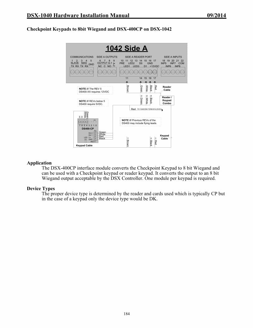
DSX-1040 Hardware Installation Manual 09/2014
184
Checkpoint Keypads to 8bit Wiegand and DSX-400CP on DSX-1042
Application
The DSX-400CP interface module converts the Checkpoint Keypad to 8 bit Wiegand and can be used with a Checkpoint keypad or reader keypad. It converts the output to an 8 bit Wiegand output acceptable by the DSX Controller. One module per keypad is required.
Device Types
The proper device type is determined by the reader and cards used which is typically CP but in the case of a keypad only the device type would be DK.
14 15 16
1042 Side A
1 3 42 5 6 7 8 9 10 11 12 13 14 15 16 17 18 19 20 21 22
GNDTX RXSLAVE
TX RXMAS
COMMUNICATIONS
NC C NO
A-2OUTPUT A-1
SIDE A OUTPUTS
LED1 LED3 D1LED2 D0 GND
+12VDCPRE
SIDE A READER PORT SIDE A INPUTS
INP5INP6
INP7INP8
COM
17
Red
Black
Wh
ite
Gree
n
Brow
n
Black
Red
Bro
wn
Gre
en
White
Red
Bla
ck
11 16 17
14 15
TO 1040CDM TERM #16 (5VDC)
16
Green
RedBlack
White
Gre
enW
hite
Reader /KeypadCombo
Keypad Cable
Reader Cable
Keypad Cable
DS400-CP
5 vGND
RA 0RA 1
7 6 5 4 3 2 1 0
LED D1
P1
P2
NC
NC
11
REV 4
NOTE /// Previous REVs of the DS400 may include flying leads.
NOTE /// REVs below 5 DS400 require 5VDC.
NOTE /// The REV 5 DS400-XX requires 12VDC

DSX-1040 Hardware Installation Manual 09/2014
185
DSX-400DM – Duress Module to DSX-1042
Application
The DSX-400DM duress module is designed to provide a duress alarm for users of keypad systems. The module monitors the data 1 and 0 lines from a Wiegand output keypad waiting for the asterisk ( * ) key hit. When the module sees the asterisk, the modules output pulls low to activate an input on the DSX panel that would be defined as “Keypad Panic”.
Implementation To implement duress with keypad access, all keypad codes must begin with a zero. This allows codes to be 4, 5, or 6 digits in length. Set the “number of digits in a keypad code” selection under location to be 1 more digit than the unique number to be used. All users will then press zero ( 0 ) followed by the remaining digits of their code. To signal a duress alarm the user will press the asterisk (*) instead of the Zero and enter the rest of their code as usual. The panels sees the * as a 0 and will grant access for the user. When the DSX-400DM sees the asterisk (*) it activates its output and trips the controller input that responds as programmed.
Note /// This example allows for an 8-bit or 8-bit Wiegand output keypad to be used. Note /// This example does not allow a 26-bit or BCD keypad to be used.
12 14 15 16 17
1042 Side A
1 3 42 5 6 7 8 9 10 11 12 13 14 15 16 17 18 19 20 21 22
GNDTX RXSLAVE
TX RXMAS
COMMUNICATIONS
NC C NO
A-2OUTPUT A-1
SIDE A OUTPUTS
LED1 LED3 D1LED2 D0 GND
+12VDCPRE
SIDE A READER PORT SIDE A INPUTS
INP5INP6
INP7INP8
COM
BR
OW
N
BLA
CK
RE
D
GR
EE
N
WH
ITE
SHIELD
BLU
EN
C1 2 34 5 67 8 9
* 0 # 16
GR
EE
N
WH
ITE
BLA
CK
1514
RE
D17
To Unused
Input
GREENWHITE
BLACKRED
DS400-DM
12 vGND
RA 0RA 1
LED
Rev 5
4th P
IN
NC
NC
NC
NC
NC
NC
NC
Isolate any unused (N/C or No
Connection) wires from others.
NOTE /// Previous REVs of the DS400 may include flying leads.
NOTE /// REVs below 5 DS400 require 5VDC.
NOTE /// The REV 5 DS400-XX requires 12VDC

DSX-1040 Hardware Installation Manual 09/2014
186
DSX-400DL – Door “Lock” Latch Controller for DSX-1042 Application
The DSX-400DL allows the user to unlock with a card read, latch the door open with a second card read and to re-lock (put to time zone) the door with a third card read. Only users with the appropriate linking level will perform this function. Non-authorized users have normal access through the door.
Operation
On the first card read, output 1 on the DSX panel activates the DPDT relay to unlock the door. Authorized user will pulse output 2 via a code to output link, if there is no second card read while the door is unlocked, the door re-locks normally. If there is a second card read by an authorized user, within the unlock time, then output 2 pulses again which triggers the DSX-400DL to trip its output that is tied to an input on the panel. This input is programmed to link to output 1 on a follow so that as long as the input is faulted, output 1 is open. A third authorized read resets the process and the door relocks.
Programming
1. Define output 1 for normal operation (time zone, etc) with State When Linked of OPEN. 2. Define output 2 to be OPEN 24hrs with State When Linked of SECURE. 3. Define a linking group that contains output 2 to pulse for 1 second. 4. Define a linking level which when read at this door will activate the linking group you
just created. 5. Define a linking group that contains output 1 to follow. 6. Define the input with no time zone to link on status change to the linking group you just
created. 7. Assign the linking level above to an authorized user (Professor). 8. Be sure to enable Linking Logic and Code to Linking Logic under location and Code to
Linking Logic under the device.
1816 177 8 9
1042 Side A
1 3 42 5 6 7 8 9 10 11 12 13 14 15 16 17 18 19 20 21 22
GNDTX RXSLAVE
TX RXMAS
COMMUNICATIONS
NC C NO
A-2OUTPUT A-1
SIDE A OUTPUTS
LED1 LED3 D1LED2 D0 GND
+12VDCPRE
SIDE A READER PORT SIDE A INPUTS
INP5INP6
INP7INP8
COM
External DPDT Relay
NC C NO NC C NO
CO
IL
DS400-DL
12 vGND
RA 1
LED
Rev 5RA 0
NC
NC
NC
NC
NC
NC
NC
NOTE /// The REV 5 DS400-XX requires 12VDC
Rev 7 - 9 1040 PDM
LOCK POWER SOURCE
TO LOCK TO PANEL
GND +VDC35 36 37
MOV
MAGLOCK
LOCK
NOTE /// Diode (1N4001) required.

DSX-1040 Hardware Installation Manual 09/2014
187
DSX-400DL – Door “Bypass” Latch Controller for DSX-1042 Application
The DSX-400DL allows an authorized user with a Linking Level to unlock with a card read, bypass the door indefinitely with a second card read and to re-arm (put to time zone) the door with a third card read. Only users with the appropriate linking level will perform this function. Non-authorized users have normal access through the door. The example shows the door connected to side B.
Operation On the first card read, output 1 on the DSX panel activates to unlock the door. Authorized user will pulse both output 2’s via a code to output link, if there is no immediate second card read, the door re-locks & re-arms normally. If there is a second card read by an authorized user, within 5 seconds, then both output 2’s pulse again which trigger the DSX-400DL to trip its output that is tied to input 5 on the panel. This input is programmed to link to output 2B and input 7B on a follow so that as long as the input 5 is faulted, input 7 is bypassed. A third authorized read resets the process and the door re-arms.
Programming
1. Define output 1 for normal operation (time zone, etc).
2. Define output 2A & 2B with no time zone and a “State When Linked To” of SECURE.
3. Define output 3 (virtual output) with no time zone and a “State When Linked To” of SECURE. This output is only used to prevent the door from staying bypassed.
4. Define input 7 for normal operation (time zone, etc). 5. Define input 5 with no time zone. 6. Define linking group A that contains output 2A to pulse 1 second and 2B for 5
seconds.. Define a Linking Level that activates group A from this device and assign it to the appropriate card(s).
7. Define linking group B that contains output 3 to pulse 15 minutes (timeout period), output 2B to follow, input 7B to follow. Assign linking group B to input 5, link on “Change of State”.
8. Define linking group C that contains output 2B and input 7B with response of time zone. Assign linking group C to output 3, perform link when OPEN.
9. Be sure to enable Linking Logic and Code to Linking Logic under location and Code to Linking Logic under the device.
DS400-DL
12 vGND
RA 1
LED
Rev 5RA 0
NC
NC
NC
NC
NC
NC
NC
1042 Side A & B
36 37 38 39
NC C NO
B-2OUTPUT B-1
SIDE B OUTPUTS
28 29 30 31 32 33 34 35
LED1 LED3 D1LED2 D0 GND
+12VDCPRE
SIDE B READER PORT
23 24 25 26 27
SIDE B INPUTS
INP5INP6
INP7INP8
COM18 19 20 21 22
SIDE A INPUTS
INP5INP6
INP7INP8
COM10 11 12 13 14 15 16 17
LED1 LED3 D1LED2 D0 GND
+12VDCPRE
SIDE A READER PORT
6 7 8 9
NC C NO
A-2OUTPUT A-1
SIDE A OUTPUTS
3923 34 3527
1K EOL
NOTE /// The REV 5 DS400-XX requires 12VDC
9 30
NOTE /// Diode (1N4001) (3) required.

DSX-1040 Hardware Installation Manual 09/2014
188
DSX-DP232 and DSX-DP485 Surge Suppression Modules DSX offers two data line surge suppression modules for use in applications where transient voltages from lightning or RF may cause damage to data communication circuits. The modules offered are the DSX-DP485 and the DSX-DP232. The DSX-DP485 is designed to protect any 5-volt data communications circuit. The DP485 would be used in the DSX system to protect the RS-485 data communications. The DSX-DP232 is designed to protect any 12-volt data communication circuit. The DP232 would be used in the DSX system to protect the RS-232 data communications. These data line protection modules offer 3 stages of surge suppression. Each line has its own voltage divider, gas discharge tube, and transzorb. Both modules appear as a 25-ohm load in series with the communications line. DSX highly recommends the use of these modules anytime the data communications is exposed to transient voltages. An example would be the RS-485 communications between controllers leaving building 1 and going into an underground conduit and entering building 2. You should place a DP485 module in each building. The first would be placed in series with the RS-485 wires after all controllers in building number 1. The second would be placed in series with the RS-485 wires before they connect to any controllers in building 2. By placing a suppression module at both ends of the circuit, you will protect the data communication circuits of the controllers in both buildings from transient voltages. Note /// DSX DP-232 and DP-485 Modules are placed at both ends of the underground or overhead cable, isolating this exposed wiring from the controllers or equipment at both ends.
DP485 ModuleField Side Protected Side
Module requires a unique ground, not same ground as Controller.It is not necessary to Earth Ground both sides of module .
TX-
RX+
TX+
RX-
TX-
RX+
TX+
RX-
DP232 ModuleField Side Protected Side
Module requires a unique ground, not same ground as Controller.It is not necessary to Earth Ground both sides of module .
TX
RX
GND
Not Used
TX
RX
GND
Not Used

DSX-1040 Hardware Installation Manual 09/2014
189
DSX-SMP System Monitoring Panel Description
The DSX-SMP is used in applications requiring an output to indicate a system problem. The DSX-SMP is connected to the Master Controller’s RS-232 or RS-485 transmit terminals. The SMP monitors the communications between the Master Controller and the Host PC or Comm Server. Anytime one of the events listed below occurs; the corresponding relay output on the DSX-1022 SMP will activate. These relay outputs can be used to activate a local indicator, digital dialer or other communications or signaling device.
Relay Definitions
The DSX-SMP monitors the Master Controller Communications for these conditions and energizes the relays to indicate: Device Communication Loss, Consecutive Access Denied Exceeded, Low Battery, and Loss of AC Power. Following is a list of the Relays, their definitions and theory of operation.
A-1 / Device Communication Loss - Activates when there is a loss of communications between the Master Controller and any Slave Controller. The relay energizes on Comm Loss and de-energizes on Comm Restoral. A-2 / Consecutive Access Denied Exceeded - Activates when the pre-set number of Access Denials has occurred at one of the System readers. The relay energizes for 5 minutes upon each alarm. B-1 / Low Battery - Activates when there is a Low Battery Condition at one of the System Controllers. The Relay energizes when there is a Low Battery condition and de-energizes when the battery condition restores to normal. B-2 / Loss of AC Power - Activates when there is a Loss of AC Power at one of the System Controllers. The Relay energizes when there is a Loss of AC Power and de-energizes when the AC Power returns to normal.
LED Operation
The LED’s on the DSX-SMP Processor should be illuminated in the following manner: Power LED = On Poll LED = Off Transaction Buffer LED = Flashing Download LED = Off Heartbeat LED = Flashing
SMP Address Switch Setting
Switches 1-7 can be left in the Off position. Switch 8 must be On.
SMP Panel Firmware Version WinDSX Software requires SMP firmware version 3105

DSX-1040 Hardware Installation Manual 09/2014
190
DSX-1022 SMP Connected to a DSX-1042, DSX-1043 or DSX-1044 Master
PC
/M
OD
EM
New DSX-MCI
TX+
TX-
RX+
RX-
GND
12V
TX
RX
59
58
57
56
55
54
53
52
5150
49
48
12345678
OFFON
TX+
TX-
RX+
RX-
TX+
TX-
RX+
RX-
TX+TX-
RX+
RX-
485 IN
485 OUT
MASTER485 IN
1022SMP
DSX-1042, DSX-1043 or DSX-1042 Master
TX RX TX RX GNDSLAVE PC - MASTER
Host PC
RXTXGND
Host PC Comm Port
12V Power from 1022 to MCI
SMP Output Characteristics:Output LED ON = Relay EnergizedOutput LED OFF = Relay De-energizedRelay Output silkscreen representsDe-energized State of Relay.When Activated :Outputs A1, B1 & B2 FollowOutput A2 will Pulse for 5 minutes.
SMP Relay Assignments
A-1 = Device Comm LossA-2 = Consecutive Access DeniedB-1 = Low BatteryB-2 = Loss of AC Power
SMP Firmware Requirements:The SMP unit requires firmware version 3105.Disconnect SMP from others before flashing others.
50' Maximum Distance
4000' Maximum Distance

DSX-1040 Hardware Installation Manual 09/2014
191
DSX-1022 SMP Testing Procedures Trouble Condition Verification
To verify the trouble condition, the output of the SMP Controller must be observed. The relay's On or Off state can be determined by the illumination of the associated output LED. The LED is illuminated to indicate the Output is On (Trouble). Use a VOM to verify that the relay energizes when the trouble condition is present and the contacts of the relay change state. The silkscreen on the SMP Controller for the outputs indicates the de-energized state (Normal).
Device Communication Loss/Output A-1
The loss of communications between controllers will activate the A-1 output. This output will energize on panel to panel Comm loss. To simulate this condition, disconnect the RS-485 Communication terminal block from the Master or one of the Slave Controllers. Check the relay as described above. Re-connect the RS-485 Comm line and the relay should de-energize.
Consecutive Access Denied Exceeded/Output A-2
This output will activate for 5 minutes. To simulate this condition, use a card or keypad code not authorized for entry. Use the card 4 times consecutively and an alarm should be transmitted and the relay activated. Verify the output as described above. The Number of Consecutive Denials at a Reader for Alarm is set under System Parameters in Setup.
Low Battery/Output B-1
This output will activate on a Low Battery Condition at any controller. To simulate these conditions follow the steps outlined below.
1. At the PC configured with “This PC is Comm Server” running WinDSX, exit Workstation and Database. 2. Move the mouse to the far right side of the start bar and double click on the time being displayed. Set the time to 9:55 AM and click on Apply. Exit the time window 3. Open Database and Workstation and wait for 10:00 AM. 4. At 10:00 AM the panel will check it's back-up battery. Before 10:01 AM disconnect the battery on one controller. The low battery voltage will illuminate the Low Battery LED and will send a report to the PC. At this same time the SMP panel will active output B-1. 5. At 10:01 AM the panel under test will shut down the battery test, extinguishing the Low Battery LED and the SMP panel will reset output B-1. 6. After completing the test, repeat the above step 2 and reset the PC time to the proper setting and reconnect the panels backup battery.
Note /// DSX-1022 system controllers will perform this test every day at 10:00 AM to 10:01 AM
automatically. If the batteries are all present and good, the Low Battery Condition will not be communicated and the SMP panel will not activate B-1.
Note /// DSX-1040 PDM system does not automatically test batteries at 10:00 AM. The test can be initiated by placing a ground on the “Battery Test Input” terminal of the PDM. The above testing procedure for the Low Battery may require modification in systems that include PDMs.
Loss of AC Power/B-2
When there is a loss of AC power to one of the controllers, relay B-2 of the SMP will activate. To simulate these conditions unplug the AC Input to the Master or one of the Slave Controllers. Check relay B-2 as described above. Re-connect the AC power to the panel and the relay B-2 should reset.

DSX-1040 Hardware Installation Manual 09/2014
192
Field Test Procedures Power-UP Check 1. Follow instructions in DSX installation manual for proper dipswitch settings and wiring connections. 2. Connect 12 VDC to terminals 40 and 41 of the DSX-1042 controller.
A. Alive LED above these terminals should blink indicating the processor is running. B. Power LED on the top right corner of the DSX-1042 should light indicate power is present.
3. Master Controller
A. LEDs at terminals 1 and 2 of the controller should blink to indicate communications with the PC. B. Download LED should light to indicate a download in progress to the Slave controllers. C. If there are Slave controllers, the Poll LED will light to indicate polling of the Slave controllers.
4. Slave Controller(s)
A. LEDs at terminals 3 and 4 of the controller will light to indicate communication with the Master controller. B. Download LED will light to indicate a download in progress from the Master. C. Poll LED will light to indicate the Master controller is polling the Slave.
5. Upon Completion of Download
A. All output indicator LEDs should be in the desired state as defined by the database. B. Input indicator LEDs will be lit for all inputs that have the E.O.L. resistor connected.
Reader Function Check 1. Go to a secure reader controlled door
A. The indicator LED on the reader should be Red to indicate a secure state and the door lock should be energized.
2. Use a valid card at the reader
A. The indicator LED on the reader should turn Green to indicate an open state and the door lock should be de-energized. B. An Access Granted message should be displayed at the PC within the Workstation Event Window.
3. Use an invalid card in the reader
A. The indicator LED should flash twice but remain Red to indicate a secure state and the door lock should remain locked. B. An Access Denied message should be displayed at the PC.
Note /// If the controller fails any of these checks, refer to trouble shooting section.

DSX-1040 Hardware Installation Manual 09/2014
193
Trouble Shooting Cannot Communicate with Master from PC in Direct Connect Mode. This is a common problem when setting up a system due to the many parameters involved in establishing the communications from the PC to the Master controller. Go through the following checklist in detail. Even if you think you have already checked an item, check it again. 1. Verify that the dip switch settings of the Master controller match the location address that you have defined in the database. If you have a direct connect Master that is to be location 1, then only dip switches 1 and 8 should be On. With all power disconnected to the controller, physically move each switch back and forth to make sure it is not set half way between the on and off position then power up the controller. 2. Verify that the dipswitches on the Master are set according to the On and Off markings on the circuit board, not the open and close markings of the dip switch. 3. Check the location definition in the PC, make sure the connect type is D for Direct and that at least devices 0&1 are defined in Database of the software. (The number of devices should always be two times the number of controllers.) 4. Check the setup program under Comm Ports, make sure that a serial port has been defined for the direct connect. The port parameters are 9600, 8, 1, N, and D. 5. Make sure there are no other programs running on the PC that are trying to use the same serial port as the DSX system. 6. Use an ohm meter to verify the RS-232 wiring is in accordance with the installation manual wiring connections for a direct connect Master. Make the necessary connections from the PC to the Master as a direct connect system. Also verify that the mode dip switch(es) on the Master Controller are set with 8 On (Master Direct Connect). Distance restrictions for RS-232 are 50 feet, if more than 50 feet and using DSX-MCI modules to span the distance verify correct terminations between MCI’s and proper power is received at both MCI modules. 7. Using Windows Explorer find the WinDSX directory and locate the kb2cw.exe file and double click on it. Make sure that CS, DB andWS are not running before running kb2cw 8. Select Comm Port from the menu at the top and set the port number to match the port used. Then set the Baud Rate to 9600, Word to 8, Stop Bits 1, and Parity to None and click on OK. The program should return a message that displays the port, baud, data length, and stop bit settings and show a single line flashing cursor. If you receive a message that says: “Port could not be initialized”, there is a hardware problem with the PC that must be corrected. 9. Press the Enter key three times. You should see a DSX> prompt returned to the screen. If you do not get this prompt continue with the trouble shooting section of this manual. If you receive the DSX> prompt, the comm port has been verified as good and you have communicated with the firmware of the Master Controller. Verify that another comm port is not the needed port. Define next Comm port and test with it.
DSX-1040 Hardware Installation Manual 09/2014
194
If the cursor is just sitting and flashing, we can continue testing the serial port and wiring. When running the KB2CW program, each time a key is pressed on the keyboard, it is transmitted out the serial port. Any data that is received by the serial port is displayed on the screen. This provides a simple method of testing the serial port by connecting the transmit signal to the receive input. This type of a connection will cause any character that is typed on the keyboard to be displayed on the screen thus testing the serial port's transmit and receive capabilities. On a 25 pin serial port pin 2 is transmit and pin 3 is receive. On a 9 pin serial port pin 3 is transmit and pin 2 is receive. 10. Connect pin 2 to pin 3 right at the computer and then type on the keyboard. If the characters typed are displayed on the screen, the serial port is functioning. If the characters are not displayed, either the serial port is bad or you are connected to the wrong serial port. Try moving the connector to the other serial port and typing in characters. 11. If the serial port test is passed, re-connect the wires at the PC Comm Port that go to the DSX Master controller. Disconnect the RS-232 wires from the Master controller and twist together the wires connected to pins 2 and 3 on the PC. Return to the computer and while running the KB2CW program, type any letter key on the keyboard and see if it is displayed on the screen. If not, then you have an open or grounded wire between the computer and the Master controller. 12. If the characters are displayed on the screen, return to the Master controller and connect the 3rd wire from the ground terminal that is connected to pin 5 on a DB-9, or pin 7 on a DB-25 serial port, to the other two wires previously connected. Return to the PC, while running the KB2CW program, type any letter key on the keyboard and see if it is displayed on the screen. If it is displayed, then you have an open ground wire between the PC and the Master controller. 13. If the characters are not displayed when the above test is run, then the serial port and the wiring are both correct. Use a voltmeter and measure between ground and the transmit and receive wires. The wire that has a negative voltage between -8 and -12 volts DC is the transmit from the computer and should be connected to the RS-232 receive of the Master controller. The other wire should not measure any voltage and should be connected to the RS-232 transmit of the Master. The ground wire of the PC should be connected to ground of the Master. Note /// If trying to perform a loopback test from the Serial Port through a DSX-MCI module, remove the RS-485 wires from the controller and connect TX+ to RX+ and TX- to RX-. This provides a means of testing the RS-485 output of the MCI module.

DSX-1040 Hardware Installation Manual 09/2014
195
Cannot Communicate with a Modem Connect Master. Follow the instructions for the above direct connect system down to step 11 to test the Comm port. After that, perform these tests. 1. Verify the wiring from the Master DSX controller to the modem according to the installation manual drawings. 2. Reset the modems by powering them and the Master controller down and up and possibly initializing the modems by using KB2CW.exe and sending it the AT&F command. The DSX panel will need to dial out once to initialize the modem after a modem is powered up. 3. Remove any other equipment that may be sharing the same telephone line. This is especially true of elevator phone equipment, as it is known to generate large amounts of noise on the phone line. The modems must be on dedicated phone lines. 4. Use a standard telephone to call the number that the Master controller is connected to and verify that the modem answers on the 3rd ring. The Master initializes its modem to answer on the third ring. The following are a few reasons why the modem may not answer the phone:
A. The PC is programmed to call the wrong number.
B. The modem at the Master controller will not answer the phone until the Master controller has attempted to call out at least once since the modem has been powered down and back up. This is due to the fact that the Master controller has to initialize the modem before it will go to the auto-answer mode.
C. The phone lines at the modem have Tip and Ring reversed. Check the polarity of the phone line. The green wire should be positive and the red wire should be negative.
D. The phone cord may be bad. Check to make sure that the modem can dial out successfully.
E. The modem may be bad.
5. Make sure that the Master's location dipswitch settings match the location number you are attempting to contact from the PC. If the PC thinks it’s calling location 4, the Master's location number should be set to 4. 6. Using kb2cw, establish communications to the modem then type “ATDT_### enter” where the _ (underscore) is a space and where #### is the telephone number of receiving modem. When the kb2cw screen reports “Connect 9600” press enter 2 to 4 times. This should cause kb2cw to show a “DSX>” prompt. What should not be seen is characters that are not recognized as common keyboard characters. If this condition exists, it is due to a noisy telephone line and should be reported to the telephone company.

DSX-1040 Hardware Installation Manual 09/2014
196
Device Communication Losses / Missed Polls. Device Communication Fails and a large number of missed polls can be seen from the 1040 Series Controllers when they are added into existing 1030 Series systems. This occurs when the RS-485 Transmit and Receive negatives have been crossed between Controllers. The problem could be undetected in existing 1030 Series systems until the 1040 Series equipment is added. Finding the problem requires a voltmeter on a low AC Voltage scale and measuring voltage at specific places. Examples for Master to Slave wired correctly:
1. Master RS485 IN, measure between tx+ and tx- = should be 2.5 – 3.0 Volts AC 2. Master RS485 IN, measure between rx+ and rx- = should be 2.5 – 3.0 Volts AC 3. Slave RS485 IN, measure between tx+ and tx- = should be 2.5 – 3.0 Volts AC 4. Slave RS485 IN, measure between rx+ and rx- = should be 2.5 – 3.0 Volts AC
Examples for Slave to Slave with correctly connected RS-485 communications.
1. 1st Slave RS485 IN, measure between tx+ and tx- = should be 1.5 – 2.5 Volts AC 2. 1st Slave RS485 IN, measure between rx+ and rx- = should be 2.5 – 3.0 Volts AC 3. 1st Slave RS485 OUT, measure between tx+ and tx- = should be 1.5 – 2.5 Volts AC 4. 1st Slave RS485 OUT, measure between rx+ and rx- = should be 2.5 – 3.0 Volts AC 5. 2nd Slave RS485 IN, measure between tx+ and tx- = should be 1.5 – 2.5 Volts AC 6. 2nd Slave RS485 IN, measure between rx+ and rx- = should be 2.5 – 3.0 Volts AC 7. 2nd Slave RS485 OUT, measure between tx+ and tx- = should be 1.5 – 2.5 Volts AC 8. 2nd Slave RS485 OUT, measure between rx+ and rx- = should be 2.5 – 3.0 Volts AC
Examples for Slave to Slave with negatives crossed between Slave 1 and Slave 2.
1. 1st Slave RS485 IN, measure between tx+ and tx- = should be 1.5 – 2.5 Volts AC 2. 1st Slave RS485 IN, measure between rx+ and rx- = should be 2.5 – 3.0 Volts AC 3. 1st Slave RS485 OUT, measure between tx+ and tx- = would be less than 1Volt AC 4. 1st Slave RS485 OUT, measure between rx+ and rx- = would be 1.0 – 1.5 Volts AC
Negatives are crossed here. 5. 2nd Slave RS485 IN, measure between tx+ and tx- = would be less than 1 Volts AC 6. 2nd Slave RS485 IN, measure between rx+ and rx- = would be 1.0 to 1.5 Volts AC 7. 2nd Slave RS485 OUT, measure between tx+ and tx- = should be 1.5 – 2.5 Volts AC 8. 2nd Slave RS485 OUT, measure between rx+ and rx- = should be 2.5 – 3.0 Volts AC

DSX-1040 Hardware Installation Manual 09/2014
197
No Master to Slave Communications. 1. Verify the address dip-switch settings of the Slave controller. While the controller has been de-energized physically move each switch back and forth to make sure it is not set halfway between the on and off position then re-power the controller. 2. Check to make sure that the communications wiring is connected according to the schematics shown for Master to Slave communications. The “Comm Slave” of the Master (terminals TX & RX) should connect to the 1040CDM “Master Internal Comm” (terminals RX and TX respectively) and should cross TX and RX between the Master and CDM, then the 1040CDM “Slave Internal Comm” (terminals TX and RX) should connect to the first slave within the enclosure at its “Slave” RX and TX and should cross TX and RX between the 1040CDM and first slave. From the first slave to the next slave one would simply terminate the Slave TX and RX to the next Slave TX and RX and not cross the connections. 3. Be sure that all controllers are earth grounded. If controllers are not properly grounded, ground current loops can be formed over the communication wires and interfere with controller communications. 4. Check within Database Location and make sure within Device that we have enough devices listed for the number of controllers. The number of devices listed should be the number of controllers times 2. So if you have 6 DSX controllers in the job, the number of devices shown should be set 12. Each DSX controller counts as 2 devices. 5. Check communication wires with an ohmmeter for continuity and ground faults.
Card Reader Error Messages Receiving Bad Card Read Messages from Card Reader. Example (Bad Card Read **26**) This message means that the DSX-1042 controller is not seeing the correct number of data bits being transmitted from the reader for the reader type that is programmed into the system. The example provided implies that the card reader read 26 bits from the card and the “Device Type” is not set to a 26 bit device type. Verify that the device type selected matches the reader and card combination in use. Check power at the reader. Check to make sure the data 1 and data 0 reader communication lines are connected properly. Measure the voltage on data 1 and data 0 of both sides of the controller. Both data 1 and data 0 should be above 3.7VDC on both sides of the controller. If voltage is low or not present on a reader data line, remove all field wiring from that reader port and test again if the voltage is present without the wire connected the field wiring is shorted or grounded. If the voltage is not present when the wire is disconnected the reader port has failed. Make sure that the field-wiring shield is connected to ground at the controller only. Receiving Parity Error Messages from the Card Reader. This message means that the controller is receiving the proper number of data bits from the reader, but the parity check is not correct. Check under the “Device, Options” definition and make sure the “Reverse Card Data” field is set correctly for your reader. The only time this field should be checked is when a Sensor Wiegand insertion card (not key) reader is connected. Even then, some cards bought from other manufacturers are built so that the “Reverse Card Data” field may need to be turned off even when you are using a Sensor Wiegand card insertion reader. Check to make sure that data 1 and data 0 are connected properly. Make sure that the card is being run through the reader in the proper direction. Make sure that the device type matches the cards and readers in use.

DSX-1040 Hardware Installation Manual 09/2014
198
No Message from Reader when Card is Used. Verify voltages on data 0 and data 1 as described in “Receiving Bad Card Read Messages from Card Reader” section above. Verify that “Display Bad Card Read Events” is enabled in the “Location, Y/N Options”. Verify the Device has a time zone assigned to it. Verify that within Workstation the reader is set to TZ by right clicking on the device. Controller Resets when the Lock is De-Energized. Either there is no MOV installed at the lock or the MOV is not functioning properly. Remove the wire connected to the positive side of the lock from the controller and physically touch the wire to the lock power source. Now pull the wire away from the power source. If you see a spark when the lock wire is removed from the power source, then your MOV is not functioning or is the wrong voltage. Replace the MOV at the lock to correct the problem. If the problem persists, place an MOV in parallel with the lock wire across the relay output of the DSX controller. If your lock power is connected to the NC side of the relay, connect the MOV across the C and NC terminals of the controller. If your lock power is connected to the NO side of the relay, connect the MOV across the C and NO terminals of the controller. Also make sure that the DSX controller is properly grounded. If the problem still exists after MOV and grounding have been verified, an isolation relay may have to be used to prevent the lock surge from affecting the DSX controller. Output 1 will not Secure. Make sure that the exit request input number 8 is not in an abnormal state. When input 8 is used as the exit request, the input must be normal hence the status LED must be On before output 1 will secure. The Input must see the 1K ohm resistor to be normal. Make sure the output relay number 1 for the device in question has an active time zone assigned to it. Output 1 only Unlocks for 1 Second. The “Door Open Detect Relock” feature has been enabled under the Device definition and the door contact input, Input 7, is in a constant abnormal state. As soon as the door is unlocked, the controller sees that the door contact is abnormal and immediately relocks the door. Correct the problem with input seven, the door position switch, or disable the Door Open Detect Relock feature. Output will not Respond to Linking Event. Make sure that the relay to be linked is in the opposite state of the programmed linking state before the link takes place. That is, if you wish a relay to be linked open, make sure that it is secure before the link takes place. Also verify the linking state is programmed correctly for the output. To program an input to output link, enable in “Location”, define the output relay, put it into a linking group, assign the linking group to the input. To program a code to output link, enable in “Location”, define the output relay or Input to link to, put it into a linking group, create an “Linking Level” with the linking group, assign the linking level to the access code with an appropriate access level (not the Master Access Level) Verify that the relay is not already linked to.

DSX-1040 Hardware Installation Manual 09/2014
199
Output 1 will not Respond to Exit Request. Be sure that the Use Inputs 7 and 8 question under the device definition is selected with a checkmark. Also make sure that the relay output is currently in the secure (Energized) state. You can tell if the output is secure by viewing it in “Workstation” or by looking at the LED located nearest the terminal strip for the output. If the LED is on, the output is secure. If the LED is off, the output is open. An output must be in the secure state before the exit request will open it. No Battery Charging Voltage. The battery fuse is blown. Replace the fuse marked BATT with the appropriate fuse. See the section on Fuses in this manual. No 12 VDC Power Output. The 12VDC fuse is blown. Measure the circuit for a short or ground and then replace the fuse. Input Will Not Set Up. Check field wiring with an ohmmeter for shorts, opens, or grounds. Remove field wiring from the controller and place a 1K-ohm resistor directly across the input. If the input still does not setup, replace the controller. No 12VDC at the PDMs Terminals 1 & 2. Check existence of 115/240VAC is going to the SWS150, AS150 or SP150 across the L & N terminals. Disconnect VDC at each Controller, cycle power on SWS150, AS150 or SP150 and reconnect one at a time. No Lock Power at 1040PDM. Check the SWS150-15, SWS150-27, SP150-15, SP150-27, SP320-27, AS100-15, AS100-24, AS150-15 or AS150-27 for 115 or 240VAC primary source input and 15VDC to 27VDC secondary voltage output. Also check the Fire Override terminals, there should be a short across them for voltage to be present at the “To Lock” area of the PDM.
DSX-1040 Hardware Installation Manual 09/2014
200
Routine Maintenance 1. Back-up battery should be replaced if the Low Battery LED lights and a Low Battery message is sent to the PC. 2. Continuity to Earth Ground should be checked periodically. (see Grounding Connections in the manual) 3. Fuses should be replaced if the corresponding indicator LED is lit on the controller or if the fuse measures voltage from one end to the other while installed. (see Replacement Fuse Specifications in the manual)
Conditions Which May Cause Undesired Operation 1. Failure to replace batteries, which have generated a Low Battery report. 2. Failure to replace blown fuses with proper fuse. See Replacement Fuse Specifications in this manual. 3. Failure to provide a good Earth Ground to the DSX-1040 series controller. See Battery and Ground Connections in this manual. 4. Failure to follow recommended cabling specifications. See Cable Specifications in this manual. 5. Failure to provide proper power. See AC Power Connections in this manual. 6. Failure to follow proper addressing conventions for Master and Slave controllers. See Master / Slave Dip-switch Settings in this manual. 7. Failure to follow communication / reader hook-up instructions. See appropriate section in this manual.

DSX-1040 Hardware Installation Manual 09/2014
201
This page is intentionally blank.

®
The Security Professionals’ First Choice