DS160 - skyazul.com part of this document may be photocopied, reproduced, ... The PAT Load Moment...
64
SIGALARM MODEL 210 DS160 Service Manual
Transcript of DS160 - skyazul.com part of this document may be photocopied, reproduced, ... The PAT Load Moment...

SIGALARM
MODEL 210
DS160
Service Manual


SkyAzúl, Equipment Solutions www.skyazul.com 301-371-6126
NOTICE SkyAzúl makes no warranty of any kind with regard to this material, including, but not limited to, the implied warranties of merchantability and/or its fitness for a particular purpose.
SkyAzúl will not be liable for errors contained in this manual or for incidental or consequential damages in connection with the furnishing, performance, or use of this manual. This document contains proprietary information, which is protected by copyright, and all rights are reserved.
No part of this document may be photocopied, reproduced, or translated to another language without the prior written consent of SkyAzúl.
SkyAzúl reserves proprietary rights to all drawings, photos and the data contained therein. The drawings, photos and data are confidential and cannot be used or reproduced without the written consent of SkyAzúl. The drawings and/or photos are subject to technical modification without prior notice.
All information in this document is subject to change without notice.
SkyAzúl, Inc. 16 Walnut Street Middletown, MD 21769 Fax 301-371-0029 [email protected]

SkyAzúl, Equipment Solutions www.skyazul.com 301-371-6126
Service Manual DS 160
SkyAzúl, Equipment Solutions www.skyazul.com 301-371-6126
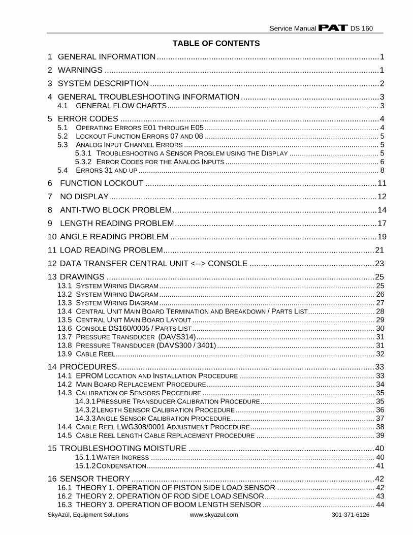
TABLE OF CONTENTS 1 GENERAL INFORMATION..................................................................................................1
2 WARNINGS .........................................................................................................................1
3 SYSTEM DESCRIPTION.....................................................................................................2
4 GENERAL TROUBLESHOOTING INFORMATION .............................................................3 4.1 GENERAL FLOW CHARTS...................................................................................................... 3
5 ERROR CODES ..................................................................................................................4 5.1 OPERATING ERRORS E01 THROUGH E05 .................................................................................... 4 5.2 LOCKOUT FUNCTION ERRORS 07 AND 08 .................................................................................... 5 5.3 ANALOG INPUT CHANNEL ERRORS .............................................................................................. 5
5.3.1 TROUBLESHOOTING A SENSOR PROBLEM USING THE DISPLAY ........................................... 5 5.3.2 ERROR CODES FOR THE ANALOG INPUTS .......................................................................... 6
5.4 ERRORS 31 AND UP .................................................................................................................... 8 6 FUNCTION LOCKOUT ......................................................................................................11
7 NO DISPLAY......................................................................................................................12
8 ANTI-TWO BLOCK PROBLEM..........................................................................................14
9 LENGTH READING PROBLEM.........................................................................................17
10 ANGLE READING PROBLEM ...........................................................................................19
11 LOAD READING PROBLEM.............................................................................................21
12 DATA TRANSFER CENTRAL UNIT <--> CONSOLE .......................................................23
13 DRAWINGS ......................................................................................................................25 13.1 SYSTEM WIRING DIAGRAM........................................................................................................ 25 13.2 SYSTEM WIRING DIAGRAM........................................................................................................ 26 13.3 SYSTEM WIRING DIAGRAM........................................................................................................ 27 13.4 CENTRAL UNIT MAIN BOARD TERMINATION AND BREAKDOWN / PARTS LIST................................ 28 13.5 CENTRAL UNIT MAIN BOARD LAYOUT ........................................................................................ 29 13.6 CONSOLE DS160/0005 / PARTS LIST........................................................................................ 30 13.7 PRESSURE TRANSDUCER (DAVS314)...................................................................................... 31 13.8 PRESSURE TRANSDUCER (DAVS300 / 3401) ............................................................................ 31 13.9 CABLE REEL............................................................................................................................. 32
14 PROCEDURES.................................................................................................................33 14.1 EPROM LOCATION AND INSTALLATION PROCEDURE ................................................................. 33 14.2 MAIN BOARD REPLACEMENT PROCEDURE................................................................................. 34 14.3 CALIBRATION OF SENSORS PROCEDURE ................................................................................... 35
14.3.1 PRESSURE TRANSDUCER CALIBRATION PROCEDURE....................................................... 35 14.3.2 LENGTH SENSOR CALIBRATION PROCEDURE ................................................................... 36 14.3.3 ANGLE SENSOR CALIBRATION PROCEDURE..................................................................... 37
14.4 CABLE REEL LWG308/0001 ADJUSTMENT PROCEDURE............................................................ 38 14.5 CABLE REEL LENGTH CABLE REPLACEMENT PROCEDURE ......................................................... 39
15 TROUBLESHOOTING MOISTURE ..................................................................................40 15.1.1 WATER INGRESS ............................................................................................................ 40 15.1.2 CONDENSATION.............................................................................................................. 41
16 SENSOR THEORY ...........................................................................................................42 16.1 THEORY 1. OPERATION OF PISTON SIDE LOAD SENSOR ............................................... 42 16.2 THEORY 2. OPERATION OF ROD SIDE LOAD SENSOR..................................................... 43 16.3 THEORY 3. OPERATION OF BOOM LENGTH SENSOR ...................................................... 44

SkyAzúl, Equipment Solutions www.skyazul.com 301-371-6126
16.4 THEORY 4. OPERATION OF ANGLE SENSOR..................................................................... 45 17 DS50C TO DS160 UPGRADE INSTALLATION ................................................................ 46
17.1 CONSOLE MOUNTING................................................................................................................ 47 17.2 CENTRAL UNIT MOUNTING ........................................................................................................ 47 17.3 SOFTWARE............................................................................................................................... 47 17.4 PRESSURE TRANSDUCER REPLACEMENT .................................................................................. 47 17.5 DS160 COMPONENT INSTALLATION PROCEDURE........................................................... 48 17.6 LMI SYSTEM TEST PROCEDURE......................................................................................... 55
General Information
SkyAzúl, Equipment Solutions www.skyazul.com 301-371-6126
1
1 GENERAL INFORMATION The PAT Load Moment Indicator (LMI) DS 160 has been designed to provide the crane operator with the essential information required to operate the machine within its design parameters. Using different sensing devices, the Load Moment Indicator monitors various crane functions and provides the operator with a continuous reading of the crane’s capacity. The readings continuously change as the crane moves through the motions needed to make the lift. The LMI provides the operator with information regarding the angle of the boom, working radius, rated load and the total calculated weight being lifted by the crane. If non permitted conditions are approached, the DS 160 Load Moment Indicator will warn the operator by sounding an audible alarm, lighting a warning light and locking out those functions that may aggravate the crane’s condition. Refer to operator’s manual 031-300-190-139 for console operating instructions.
2 WARNINGS The LMI is an operational aid that warns a crane operator of approaching overload conditions and of over hoist conditions that could cause damage to equipment and personnel. The device is not, and shall not, be a substitute for good operator judgment, experience and use of accepted safe crane operating procedures. The responsibility for the safe crane operation shall remain with the crane operator who shall ensure that all warnings and instructions supplied are fully understood and observed. Prior to operating the crane, the operator must carefully and thoroughly read and understand the information in this manual to ensure that he knows the operation and limitations of indicator and crane. Proper functioning depends upon proper daily inspection and observance of the operating instructions set forth in this manual. Refer to Section Pre-Operation Inspection and Calibration Verification of the operator’s manual.
The LMI can only work correctly, if all adjustments have been properly set. For correct adjustment, the operator has to answer thoroughly and correctly all questions asked during the setup procedure in accordance with the real rigging state of the crane. To prevent material damage and serious or even fatal accidents, the correct adjustment of the LMI has to be ensured before starting the crane operation.
Service Manual DS 160
SkyAzúl, Equipment Solutions www.skyazul.com 301-371-6126
2
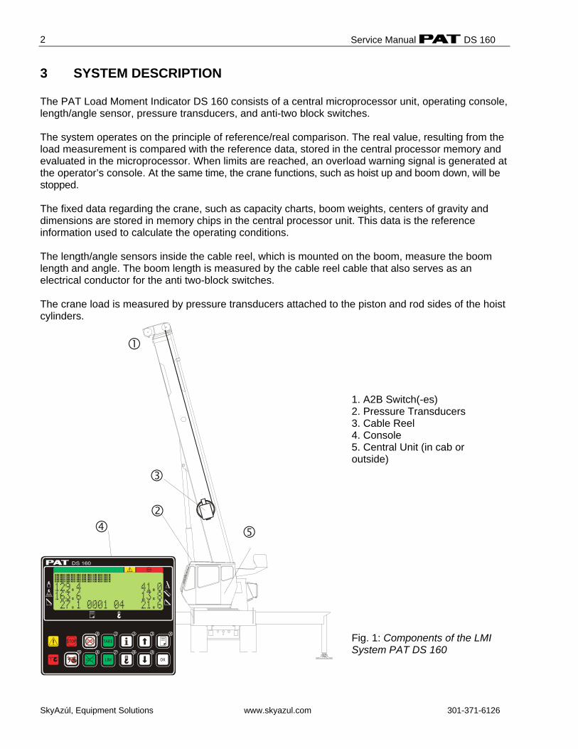
3 SYSTEM DESCRIPTION The PAT Load Moment Indicator DS 160 consists of a central microprocessor unit, operating console, length/angle sensor, pressure transducers, and anti-two block switches. The system operates on the principle of reference/real comparison. The real value, resulting from the load measurement is compared with the reference data, stored in the central processor memory and evaluated in the microprocessor. When limits are reached, an overload warning signal is generated at the operator’s console. At the same time, the crane functions, such as hoist up and boom down, will be stopped. The fixed data regarding the crane, such as capacity charts, boom weights, centers of gravity and dimensions are stored in memory chips in the central processor unit. This data is the reference information used to calculate the operating conditions. The length/angle sensors inside the cable reel, which is mounted on the boom, measure the boom length and angle. The boom length is measured by the cable reel cable that also serves as an electrical conductor for the anti two-block switches. The crane load is measured by pressure transducers attached to the piston and rod sides of the hoist cylinders.
1 2
7
3 4
5 6 98
0
LIM OK
TARESTOP
1. A2B Switch(-es) 2. Pressure Transducers 3. Cable Reel 4. Console 5. Central Unit (in cab or outside) Fig. 1: Components of the LMI System PAT DS 160
General Flow Charts
SkyAzúl, Equipment Solutions www.skyazul.com 301-371-6126
3
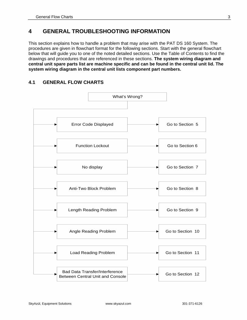
4 GENERAL TROUBLESHOOTING INFORMATION This section explains how to handle a problem that may arise with the PAT DS 160 System. The procedures are given in flowchart format for the following sections. Start with the general flowchart below that will guide you to one of the noted detailed sections. Use the Table of Contents to find the drawings and procedures that are referenced in these sections. The system wiring diagram and central unit spare parts list are machine specific and can be found in the central unit lid. The system wiring diagram in the central unit lists component part numbers.
4.1 GENERAL FLOW CHARTS
What’s Wrong?
Function Lockout Go to Section 6
No display
Anti-Two Block Problem
Angle Reading Problem
Bad Data Transfer/InterferenceBetween Central Unit and Console
Load Reading Problem
Go to Section 7
Go to Section 8
Go to Section 9
Go to Section 10
Go to Section 12
Length Reading Problem
Go to Section 11
Error Code Displayed Go to Section 5
Service Manual DS 160
SkyAzúl, Equipment Solutions www.skyazul.com 301-371-6126
4
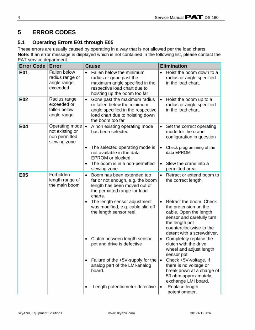
5 ERROR CODES 5.1 Operating Errors E01 through E05 These errors are usually caused by operating in a way that is not allowed per the load charts. Note: If an error message is displayed which is not contained in the following list, please contact the PAT service department. Error Code Error Cause Elimination E01 Fallen below
radius range or angle range exceeded
• Fallen below the minimum radius or gone past the maximum angle specified in the respective load chart due to hoisting up the boom too far
• Hoist the boom down to a radius or angle specified in the load chart.
E02 Radius range exceeded or fallen below angle range
• Gone past the maximum radius or fallen below the minimum angle specified in the respective load chart due to hoisting down the boom too far
• Hoist the boom up to a radius or angle specified in the load chart.
E04
Operating mode not existing or non permitted slewing zone
• A non existing operating mode has been selected
• Set the correct operating mode for the crane configuration in question
• The selected operating mode is not available in the data EPROM or blocked.
• Check programming of the data EPROM
• The boom is in a non-permitted slewing zone
• Slew the crane into a permitted area.
E05
Forbidden length range of the main boom
• Boom has been extended too far or not enough, e.g. the boom length has been moved out of the permitted range for load charts.
• The length sensor adjustment was modified, e.g. cable slid off the length sensor reel.
• Clutch between length sensor
pot and drive is defective • Failure of the +5V-supply for the
analog part of the LMI-analog board.
• Length potentiometer defective.
• Retract or extend boom to the correct length.
• Retract the boom. Check
the pretension on the cable. Open the length sensor and carefully turn the length pot counterclockwise to the detent with a screwdriver.
• Completely replace the clutch with the drive wheel and adjust length sensor pot
• Check +5V-voltage. If there is no voltage or break down at a charge of 50 ohm approximately, exchange LMI board.
• Replace length potentiometer.
Error Codes
SkyAzúl, Equipment Solutions www.skyazul.com 301-371-6126
5
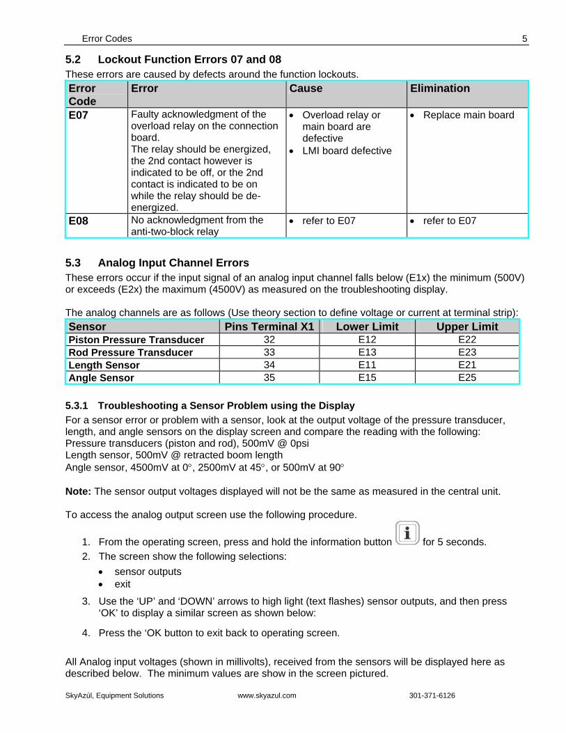
5.2 Lockout Function Errors 07 and 08 These errors are caused by defects around the function lockouts. Error Code
Error Cause Elimination
E07 Faulty acknowledgment of the overload relay on the connection board. The relay should be energized, the 2nd contact however is indicated to be off, or the 2nd contact is indicated to be on while the relay should be de-energized.
• Overload relay or main board are defective
• LMI board defective
• Replace main board
E08 No acknowledgment from the anti-two-block relay
• refer to E07 • refer to E07
5.3 Analog Input Channel Errors These errors occur if the input signal of an analog input channel falls below (E1x) the minimum (500V) or exceeds (E2x) the maximum (4500V) as measured on the troubleshooting display. The analog channels are as follows (Use theory section to define voltage or current at terminal strip): Sensor Pins Terminal X1 Lower Limit Upper Limit Piston Pressure Transducer 32 E12 E22 Rod Pressure Transducer 33 E13 E23 Length Sensor 34 E11 E21 Angle Sensor 35 E15 E25
5.3.1 Troubleshooting a Sensor Problem using the Display For a sensor error or problem with a sensor, look at the output voltage of the pressure transducer, length, and angle sensors on the display screen and compare the reading with the following: Pressure transducers (piston and rod), 500mV @ 0psi Length sensor, 500mV @ retracted boom length Angle sensor, 4500mV at 0°, 2500mV at 45°, or 500mV at 90° Note: The sensor output voltages displayed will not be the same as measured in the central unit. To access the analog output screen use the following procedure.
1. From the operating screen, press and hold the information button for 5 seconds. 2. The screen show the following selections:
• sensor outputs • exit
3. Use the ‘UP’ and ‘DOWN’ arrows to high light (text flashes) sensor outputs, and then press ‘OK’ to display a similar screen as shown below:
4. Press the ‘OK button to exit back to operating screen. All Analog input voltages (shown in millivolts), received from the sensors will be displayed here as described below. The minimum values are show in the screen pictured.

Service Manual DS 160
SkyAzúl, Equipment Solutions www.skyazul.com 301-371-6126
6
5.3.2 Error Codes for the Analog Inputs If it exceeds these limits, the following errors are triggered: (NOTE: the upper limit follows the lower limit error, i.e. 11 and 21, 12 and 22, 13 and 23…) Error Code Error Cause Elimination E11
Fallen below limit for the measuring channel "Length telescopic boom".
• Length sensor potentiometer defective.
• Electronic board in the
measuring channel defective.
• Replace length sensor potentiometer.
• Replace LMI board.
E21
Upper limit value for measuring channel "length telescopic boom" exceeded.
• Length sensor potentiometer defective.
• Electronic part in the
measuring channel defective.
• Replace length sensor potentiometer.
• Replace LMI board.
E12
Fallen below the lower limit value in the measuring channel "pressure piston side"
• Cable between the central unit and pressure transducers defective or water inside the plugs
• Check cable as well as plugs, replace, if need be.
• Pressure transducer is defective.
• Replace pressure transducer
• Electronic component in the measuring channel is defective.
• Replace LMI main board or processor board.
E22
Upper limit value in measuring channel "pressure piston side" has been exceeded
• refer to E12
• refer to E12
Error Codes
SkyAzúl, Equipment Solutions www.skyazul.com 301-371-6126
7
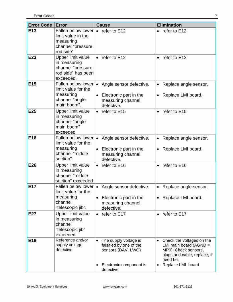
Error Code Error Cause Elimination E13
Fallen below lower limit value in the measuring channel "pressure rod side"
• refer to E12 • refer to E12
E23
Upper limit value in measuring channel "pressure rod side" has been exceeded.
• refer to E12
• refer to E12
E15
Fallen below lower limit value for the measuring channel "angle main boom".
• Angle sensor defective.
• Electronic part in the measuring channel defective.
• Replace angle sensor.
• Replace LMI board.
E25
Upper limit value in measuring channel "angle main boom" exceeded
• refer to E15 • refer to E15
E16
Fallen below lower limit value for the measuring channel "middle section".
• Angle sensor defective.
• Electronic part in the measuring channel defective.
• Replace angle sensor.
• Replace LMI board.
E26
Upper limit value in measuring channel "middle section" exceeded
• refer to E16 • refer to E16
E17
Fallen below lower limit value for the measuring channel "telescopic jib".
• Angle sensor defective.
• Electronic part in the measuring channel defective.
• Replace angle sensor.
• Replace LMI board.
E27
Upper limit value in measuring channel "telescopic jib" exceeded
• refer to E17 • refer to E17
E19
Reference and/or supply voltage defective
• The supply voltage is falsified by one of the sensors (DAV, LWG)
• Check the voltages on the LMI main board (AGND = MP0). Check sensors, plugs and cable, replace, if need be.
• Electronic component is defective
• Replace LMI board
Service Manual DS 160
SkyAzúl, Equipment Solutions www.skyazul.com 301-371-6126
8
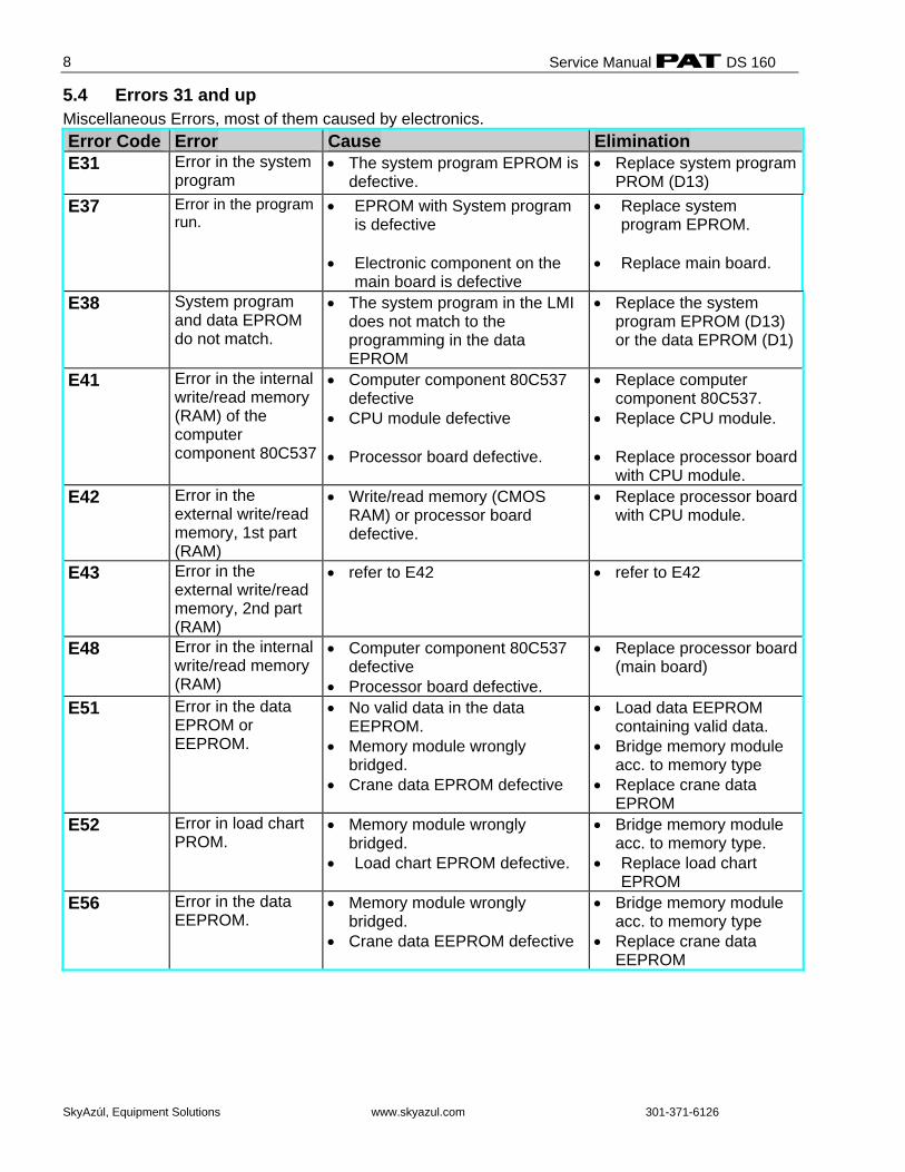
5.4 Errors 31 and up Miscellaneous Errors, most of them caused by electronics. Error Code Error Cause Elimination E31
Error in the system program
• The system program EPROM is defective.
• Replace system program PROM (D13)
E37 Error in the program run.
• EPROM with System program is defective
• Electronic component on the
main board is defective
• Replace system program EPROM.
• Replace main board.
E38
System program and data EPROM do not match.
• The system program in the LMI does not match to the programming in the data EPROM
• Replace the system program EPROM (D13) or the data EPROM (D1)
E41
Error in the internal write/read memory (RAM) of the computer component 80C537
• Computer component 80C537 defective
• CPU module defective • Processor board defective.
• Replace computer component 80C537.
• Replace CPU module. • Replace processor board
with CPU module. E42
Error in the external write/read memory, 1st part (RAM)
• Write/read memory (CMOS RAM) or processor board defective.
• Replace processor board with CPU module.
E43 Error in the external write/read memory, 2nd part (RAM)
• refer to E42 • refer to E42
E48
Error in the internal write/read memory (RAM)
• Computer component 80C537 defective
• Processor board defective.
• Replace processor board (main board)
E51
Error in the data EPROM or EEPROM.
• No valid data in the data EEPROM.
• Memory module wrongly bridged.
• Crane data EPROM defective
• Load data EEPROM containing valid data.
• Bridge memory module acc. to memory type
• Replace crane data EPROM
E52
Error in load chart PROM.
• Memory module wrongly bridged.
• Load chart EPROM defective.
• Bridge memory module acc. to memory type.
• Replace load chart EPROM
E56
Error in the data EEPROM.
• Memory module wrongly bridged.
• Crane data EEPROM defective
• Bridge memory module acc. to memory type
• Replace crane data EEPROM
Error Codes
SkyAzúl, Equipment Solutions www.skyazul.com 301-371-6126
9
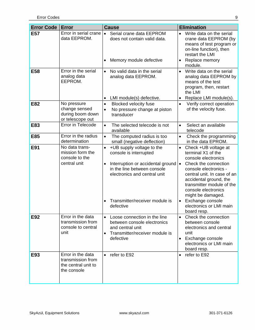
Error Code Error Cause Elimination E57
Error in serial crane data EEPROM.
• Serial crane data EEPROM does not contain valid data.
• Memory module defective
• Write data on the serial crane data EEPROM (by means of test program or on-line function), then restart the LMI
• Replace memory module.
E58
Error in the serial analog data EEPROM.
• No valid data in the serial analog data EEPROM.
• LMI module(s) defective.
• Write data on the serial analog data EEPROM by means of the test program, then, restart the LMI
• Replace LMI module(s). E82 No pressure
change sensed during boom down or telescope out
• Blocked velocity fuse • No pressure change at piston
transducer
• Verify correct operation of the velocity fuse.
E83 Error in Telecode • The selected telecode is not available
• Select an available telecode
E85 Error in the radius determination
• The computed radius is too small (negative deflection)
• Check the programming in the data EPROM.
E91 No data trans-mission form the console to the
• +UB supply voltage to the console is interrupted
• Check +UB voltage at terminal X1 of the console electronics
central unit • Interruption or accidental ground in the line between console electronics and central unit
• Check the connection console electronics - central unit. In case of an accidental ground, the transmitter module of the console electronics might be damaged.
• Transmitter/receiver module is defective
• Exchange console electronics or LMI main board resp.
E92 Error in the data transmission from console to central unit
• Loose connection in the line between console electronics and central unit
• Transmitter/receiver module is defective
• Check the connection between console electronics and central unit
• Exchange console electronics or LMI main board resp.
E93 Error in the data transmission from the central unit to the console
• refer to E92 • refer to E92
Service Manual DS 160
SkyAzúl, Equipment Solutions www.skyazul.com 301-371-6126
10
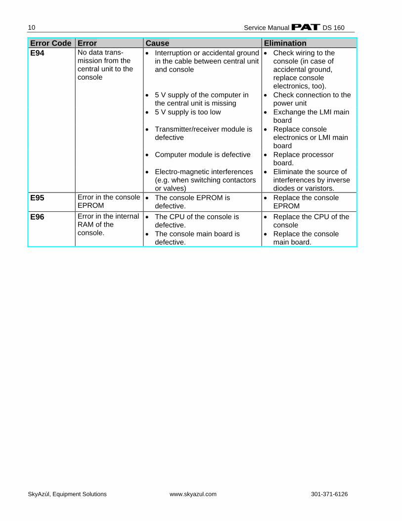
Error Code Error Cause Elimination E94
No data trans-mission from the central unit to the console
• Interruption or accidental ground in the cable between central unit and console
• Check wiring to the console (in case of accidental ground, replace console electronics, too).
• 5 V supply of the computer in the central unit is missing
• Check connection to the power unit
• 5 V supply is too low • Exchange the LMI main board
• Transmitter/receiver module is defective
• Replace console electronics or LMI main board
• Computer module is defective • Replace processor board.
• Electro-magnetic interferences (e.g. when switching contactors or valves)
• Eliminate the source of interferences by inverse diodes or varistors.
E95
Error in the console EPROM
• The console EPROM is defective.
• Replace the console EPROM
E96
Error in the internal RAM of the console.
• The CPU of the console is defective.
• The console main board is defective.
• Replace the CPU of the console
• Replace the console main board.
Error Codes
SkyAzúl, Equipment Solutions www.skyazul.com 301-371-6126
11
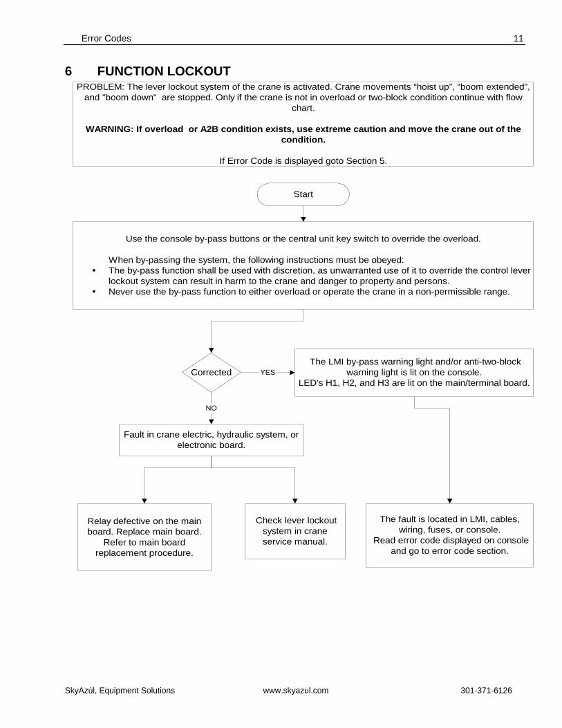
6 FUNCTION LOCKOUT
Fault in crane electric, hydraulic system, orelectronic board.
PROBLEM: The lever lockout system of the crane is activated. Crane movements “hoist up”, “boom extended”,and "boom down" are stopped. Only if the crane is not in overload or two-block condition continue with flow
chart.
WARNING: If overload or A2B condition exists, use extreme caution and move the crane out of thecondition.
If Error Code is displayed goto Section 5.
Corrected
Check lever lockoutsystem in craneservice manual.
Relay defective on the mainboard. Replace main board.
Refer to main boardreplacement procedure.
The LMI by-pass warning light and/or anti-two-blockwarning light is lit on the console.
LED's H1, H2, and H3 are lit on the main/terminal board.
The fault is located in LMI, cables,wiring, fuses, or console.
Read error code displayed on consoleand go to error code section.
Start
Use the console by-pass buttons or the central unit key switch to override the overload.
When by-passing the system, the following instructions must be obeyed:The by-pass function shall be used with discretion, as unwarranted use of it to override the control leverlockout system can result in harm to the crane and danger to property and persons.Never use the by-pass function to either overload or operate the crane in a non-permissible range.
YES
NO
Service Manual DS 160
SkyAzúl, Equipment Solutions www.skyazul.com 301-371-6126
12
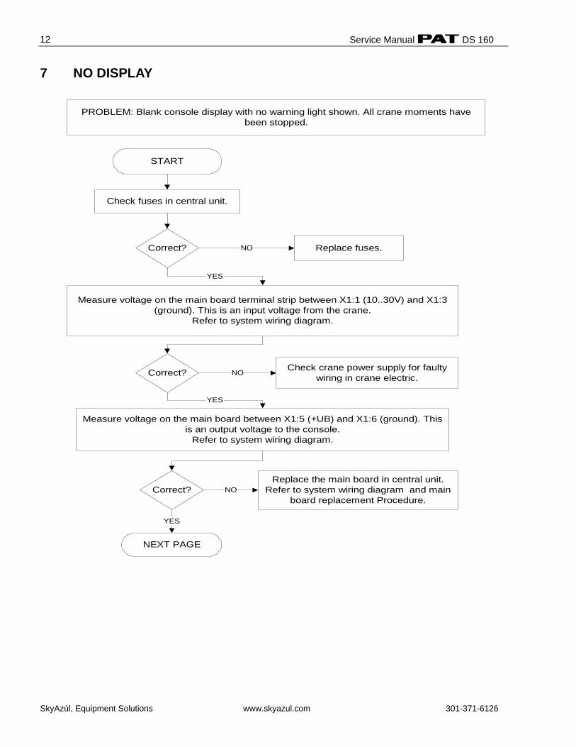
7 NO DISPLAY
PROBLEM: Blank console display with no warning light shown. All crane moments havebeen stopped.
Measure voltage on the main board terminal strip between X1:1 (10..30V) and X1:3(ground). This is an input voltage from the crane.
Refer to system wiring diagram.
Check fuses in central unit.
Replace fuses.
Measure voltage on the main board between X1:5 (+UB) and X1:6 (ground). Thisis an output voltage to the console.
Refer to system wiring diagram.
NEXT PAGE
START
NO
Check crane power supply for faultywiring in crane electric.NO
YES
YES
NOReplace the main board in central unit.
Refer to system wiring diagram and mainboard replacement Procedure.
YES
Correct?
Correct?
Correct?
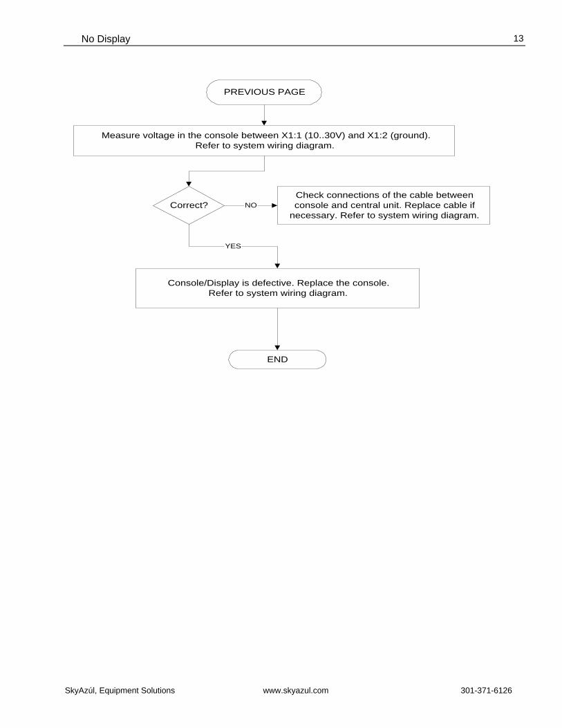
No Display
SkyAzúl, Equipment Solutions www.skyazul.com 301-371-6126
13
Console/Display is defective. Replace the console.Refer to system wiring diagram.
Check connections of the cable betweenconsole and central unit. Replace cable if
necessary. Refer to system wiring diagram.
END
Correct?
PREVIOUS PAGE
NO
Measure voltage in the console between X1:1 (10..30V) and X1:2 (ground).Refer to system wiring diagram.
YES
Service Manual DS 160
SkyAzúl, Equipment Solutions www.skyazul.com 301-371-6126
14
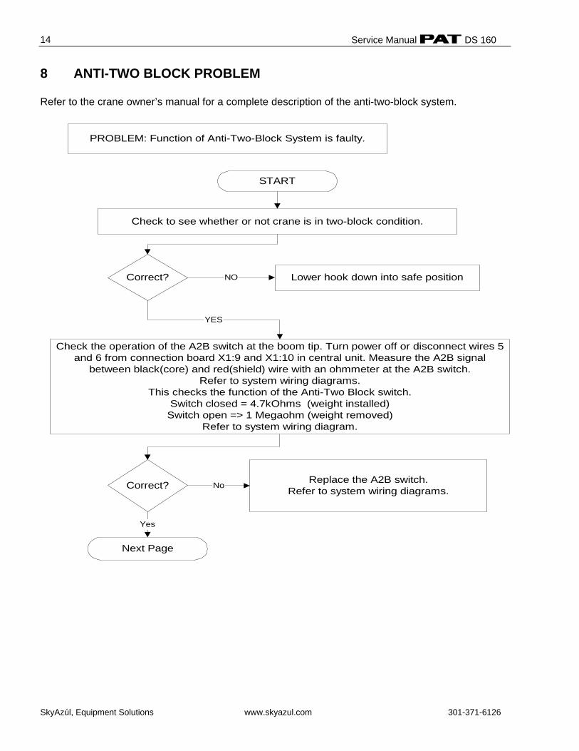
8 ANTI-TWO BLOCK PROBLEM Refer to the crane owner’s manual for a complete description of the anti-two-block system.
PROBLEM: Function of Anti-Two-Block System is faulty.
START
Check to see whether or not crane is in two-block condition.
Correct? Lower hook down into safe position
Check the operation of the A2B switch at the boom tip. Turn power off or disconnect wires 5and 6 from connection board X1:9 and X1:10 in central unit. Measure the A2B signal
between black(core) and red(shield) wire with an ohmmeter at the A2B switch.Refer to system wiring diagrams.
This checks the function of the Anti-Two Block switch.Switch closed = 4.7kOhms (weight installed)Switch open => 1 Megaohm (weight removed)
Refer to system wiring diagram.
Replace the A2B switch.Refer to system wiring diagrams.
Next Page
Correct? No
Yes
NO
YES
Anti-Two Block Problem
SkyAzúl, Equipment Solutions www.skyazul.com 301-371-6126
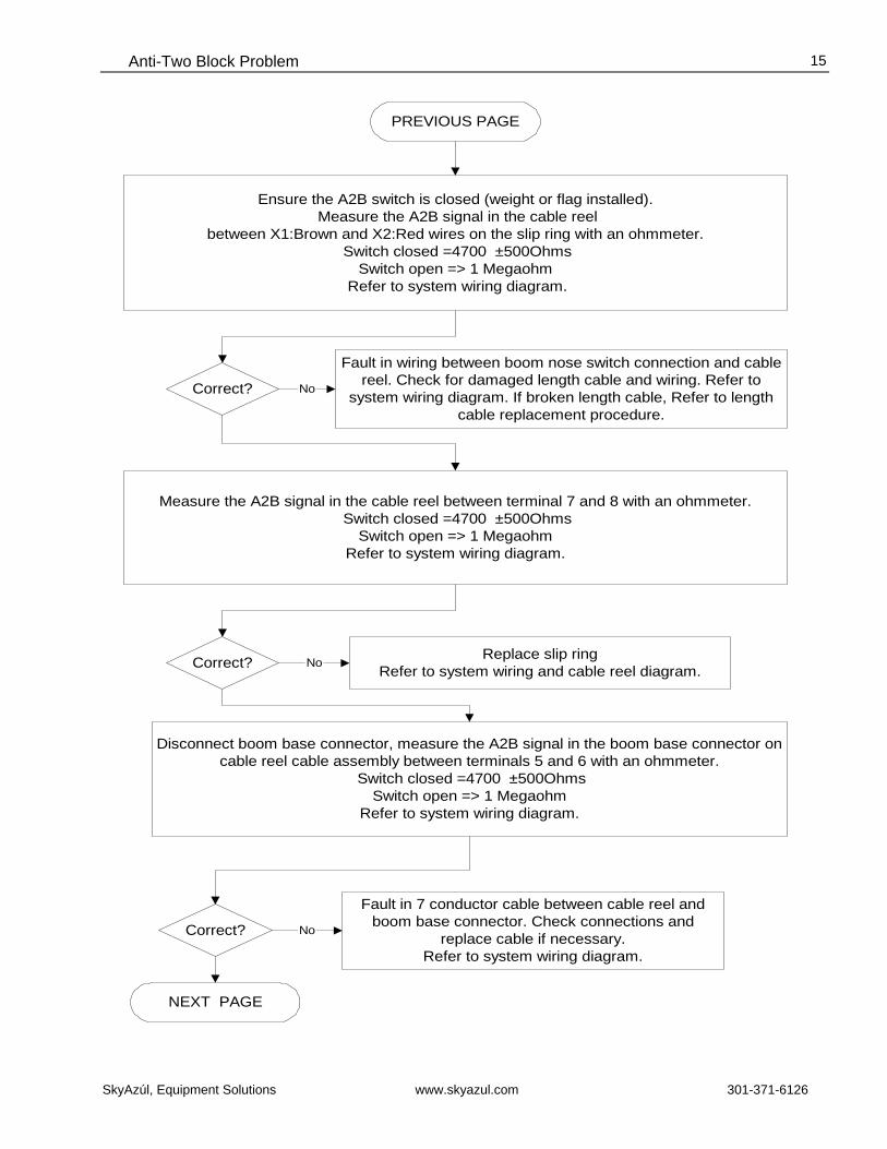
15
Fault in wiring between boom nose switch connection and cablereel. Check for damaged length cable and wiring. Refer to
system wiring diagram. If broken length cable, Refer to lengthcable replacement procedure.
PREVIOUS PAGE
Ensure the A2B switch is closed (weight or flag installed). Measure the A2B signal in the cable reel
between X1:Brown and X2:Red wires on the slip ring with an ohmmeter. Switch closed =4700 ±500Ohms
Switch open => 1 Megaohm Refer to system wiring diagram.
Correct? No
Measure the A2B signal in the cable reel between terminal 7 and 8 with an ohmmeter. Switch closed =4700 ±500Ohms
Switch open => 1 MegaohmRefer to system wiring diagram.
Replace slip ringRefer to system wiring and cable reel diagram.Correct? No
Disconnect boom base connector, measure the A2B signal in the boom base connector oncable reel cable assembly between terminals 5 and 6 with an ohmmeter.
Switch closed =4700 ±500OhmsSwitch open => 1 Megaohm
Refer to system wiring diagram.
No
Fault in 7 conductor cable between cable reel andboom base connector. Check connections and
replace cable if necessary.Refer to system wiring diagram.
Correct?
NEXT PAGE
Service Manual DS 160
SkyAzúl, Equipment Solutions www.skyazul.com 301-371-6126
16
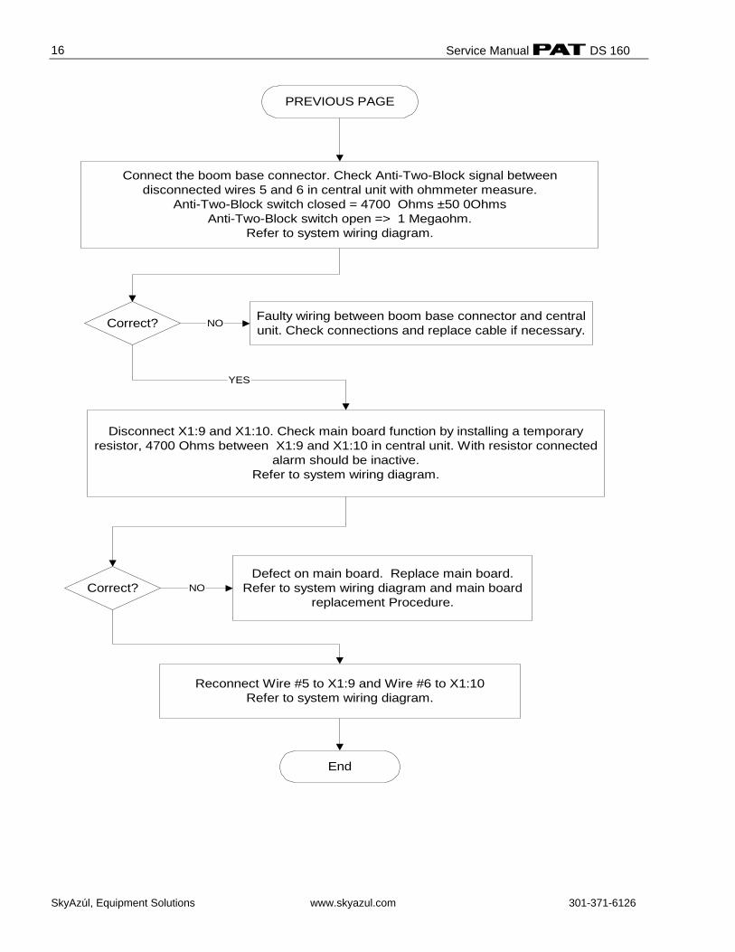
Defect on main board. Replace main board.Refer to system wiring diagram and main board
replacement Procedure.
PREVIOUS PAGE
Correct? Faulty wiring between boom base connector and centralunit. Check connections and replace cable if necessary.
Disconnect X1:9 and X1:10. Check main board function by installing a temporaryresistor, 4700 Ohms between X1:9 and X1:10 in central unit. With resistor connected
alarm should be inactive.Refer to system wiring diagram.
Correct?
End
NO
YES
NO
Connect the boom base connector. Check Anti-Two-Block signal betweendisconnected wires 5 and 6 in central unit with ohmmeter measure.
Anti-Two-Block switch closed = 4700 Ohms ±50 0OhmsAnti-Two-Block switch open => 1 Megaohm.
Refer to system wiring diagram.
Reconnect Wire #5 to X1:9 and Wire #6 to X1:10Refer to system wiring diagram.
Length Reading Problem
SkyAzúl, Equipment Solutions www.skyazul.com 301-371-6126
17
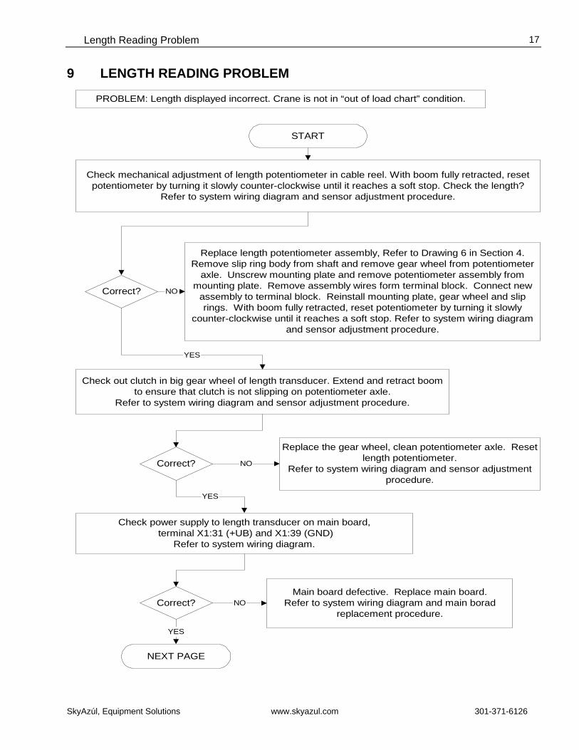
9 LENGTH READING PROBLEM
Check out clutch in big gear wheel of length transducer. Extend and retract boomto ensure that clutch is not slipping on potentiometer axle.
Refer to system wiring diagram and sensor adjustment procedure.
Replace length potentiometer assembly, Refer to Drawing 6 in Section 4.Remove slip ring body from shaft and remove gear wheel from potentiometer
axle. Unscrew mounting plate and remove potentiometer assembly frommounting plate. Remove assembly wires form terminal block. Connect new
assembly to terminal block. Reinstall mounting plate, gear wheel and sliprings. With boom fully retracted, reset potentiometer by turning it slowly
counter-clockwise until it reaches a soft stop. Refer to system wiring diagramand sensor adjustment procedure.
Check mechanical adjustment of length potentiometer in cable reel. With boom fully retracted, resetpotentiometer by turning it slowly counter-clockwise until it reaches a soft stop. Check the length?
Refer to system wiring diagram and sensor adjustment procedure.
START
PROBLEM: Length displayed incorrect. Crane is not in “out of load chart” condition.
Replace the gear wheel, clean potentiometer axle. Resetlength potentiometer.
Refer to system wiring diagram and sensor adjustmentprocedure.
Check power supply to length transducer on main board, terminal X1:31 (+UB) and X1:39 (GND)
Refer to system wiring diagram.
Main board defective. Replace main board.Refer to system wiring diagram and main borad
replacement procedure.
NEXT PAGE
Correct?
Correct?
Correct?
NO
NO
YES
NO
YES
YES
Service Manual DS 160
SkyAzúl, Equipment Solutions www.skyazul.com 301-371-6126
18
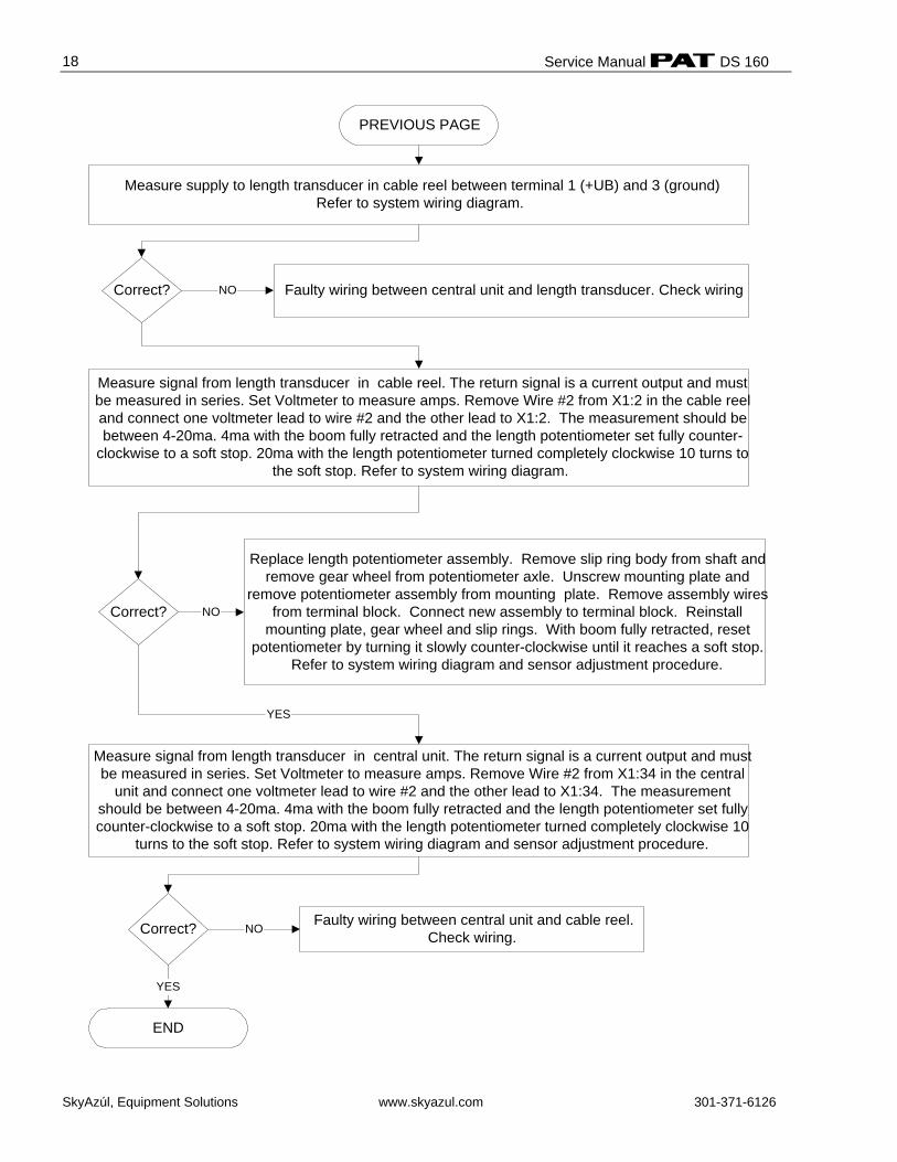
Measure supply to length transducer in cable reel between terminal 1 (+UB) and 3 (ground)Refer to system wiring diagram.
Replace length potentiometer assembly. Remove slip ring body from shaft andremove gear wheel from potentiometer axle. Unscrew mounting plate and
remove potentiometer assembly from mounting plate. Remove assembly wiresfrom terminal block. Connect new assembly to terminal block. Reinstall
mounting plate, gear wheel and slip rings. With boom fully retracted, resetpotentiometer by turning it slowly counter-clockwise until it reaches a soft stop.
Refer to system wiring diagram and sensor adjustment procedure.
Measure signal from length transducer in central unit. The return signal is a current output and mustbe measured in series. Set Voltmeter to measure amps. Remove Wire #2 from X1:34 in the central
unit and connect one voltmeter lead to wire #2 and the other lead to X1:34. The measurementshould be between 4-20ma. 4ma with the boom fully retracted and the length potentiometer set fullycounter-clockwise to a soft stop. 20ma with the length potentiometer turned completely clockwise 10
turns to the soft stop. Refer to system wiring diagram and sensor adjustment procedure.
PREVIOUS PAGE
Faulty wiring between central unit and cable reel.Check wiring.Correct?
END
Correct? NO
YES
NO
Faulty wiring between central unit and length transducer. Check wiringCorrect? NO
Measure signal from length transducer in cable reel. The return signal is a current output and mustbe measured in series. Set Voltmeter to measure amps. Remove Wire #2 from X1:2 in the cable reeland connect one voltmeter lead to wire #2 and the other lead to X1:2. The measurement should bebetween 4-20ma. 4ma with the boom fully retracted and the length potentiometer set fully counter-
clockwise to a soft stop. 20ma with the length potentiometer turned completely clockwise 10 turns tothe soft stop. Refer to system wiring diagram.
YES
Angle Reading Problem
SkyAzúl, Equipment Solutions www.skyazul.com 301-371-6126
19
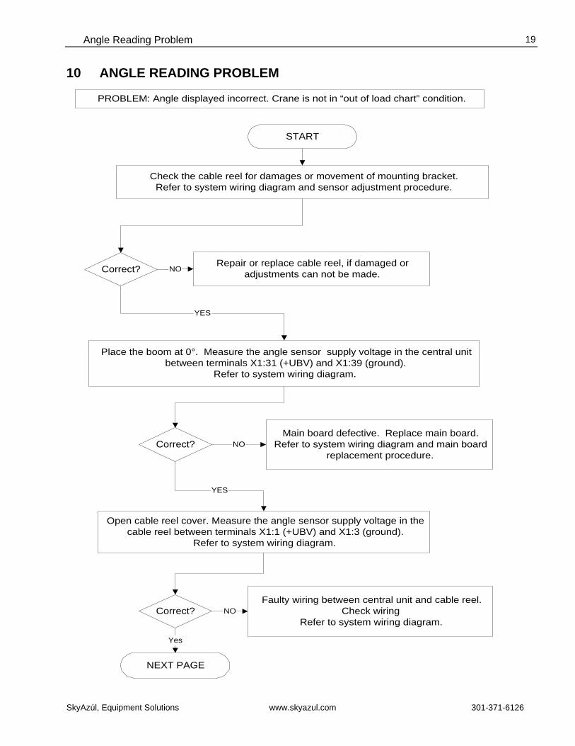
10 ANGLE READING PROBLEM
Place the boom at 0°. Measure the angle sensor supply voltage in the central unitbetween terminals X1:31 (+UBV) and X1:39 (ground).
Refer to system wiring diagram.
Repair or replace cable reel, if damaged oradjustments can not be made.
Check the cable reel for damages or movement of mounting bracket.Refer to system wiring diagram and sensor adjustment procedure.
START
PROBLEM: Angle displayed incorrect. Crane is not in “out of load chart” condition.
Open cable reel cover. Measure the angle sensor supply voltage in thecable reel between terminals X1:1 (+UBV) and X1:3 (ground).
Refer to system wiring diagram.
Faulty wiring between central unit and cable reel.Check wiring
Refer to system wiring diagram.
Main board defective. Replace main board.Refer to system wiring diagram and main board
replacement procedure.
NEXT PAGE
Correct?
Correct?
Correct?
NO
NO
Yes
NO
YES
YES
Service Manual DS 160
SkyAzúl, Equipment Solutions www.skyazul.com 301-371-6126
20
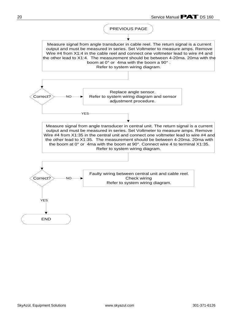
Measure signal from angle transducer in cable reel. The return signal is a currentoutput and must be measured in series. Set Voltmeter to measure amps. RemoveWire #4 from X1:4 in the cable reel and connect one voltmeter lead to wire #4 and
the other lead to X1:4. The measurement should be between 4-20ma. 20ma with theboom at 0° or 4ma with the boom a 90° .
Refer to system wiring diagram.
Faulty wiring between central unit and cable reel.Check wiring
Refer to system wiring diagram.
PREVIOUS PAGE
END
Correct? NO
YES
Replace angle sensor.Refer to system wiring diagram and sensor
adjustment procedure.Correct? NO
Measure signal from angle transducer in central unit. The return signal is a currentoutput and must be measured in series. Set Voltmeter to measure amps. Remove
Wire #4 from X1:35 in the central unit and connect one voltmeter lead to wire #4 andthe other lead to X1:35. The measurement should be between 4-20ma. 20ma with
the boom at 0° or 4ma with the boom at 90°. Connect wire 4 to terminal X1:35.Refer to system wiring diagram.
YES
Load Reading Problem
SkyAzúl, Equipment Solutions www.skyazul.com 301-371-6126
21
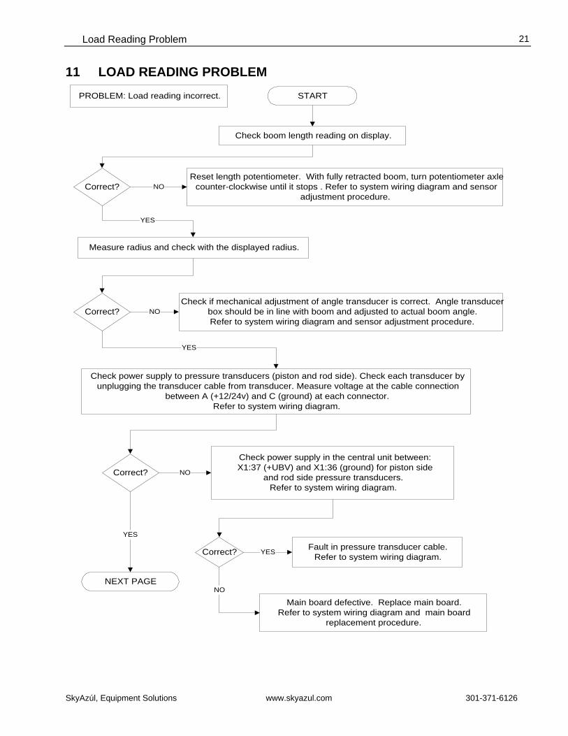
11 LOAD READING PROBLEM
Measure radius and check with the displayed radius.
Check boom length reading on display.
PROBLEM: Load reading incorrect. START
Reset length potentiometer. With fully retracted boom, turn potentiometer axlecounter-clockwise until it stops . Refer to system wiring diagram and sensor
adjustment procedure.
Check power supply in the central unit between: X1:37 (+UBV) and X1:36 (ground) for piston side
and rod side pressure transducers.Refer to system wiring diagram.
Check if mechanical adjustment of angle transducer is correct. Angle transducerbox should be in line with boom and adjusted to actual boom angle.Refer to system wiring diagram and sensor adjustment procedure.
Check power supply to pressure transducers (piston and rod side). Check each transducer byunplugging the transducer cable from transducer. Measure voltage at the cable connection
between A (+12/24v) and C (ground) at each connector.Refer to system wiring diagram.
NEXT PAGE
Correct?
Correct?
NO
YES
Correct? NO
YES
YES
NO
Fault in pressure transducer cable.Refer to system wiring diagram.Correct? YES
NO
Main board defective. Replace main board.Refer to system wiring diagram and main board
replacement procedure.
Service Manual DS 160
SkyAzúl, Equipment Solutions www.skyazul.com 301-371-6126
22
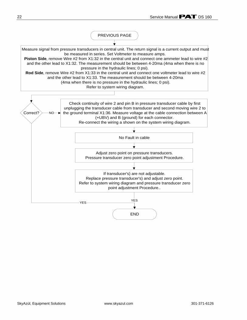
PREVIOUS PAGE
Correct?
No Fault in cable
If transducer's) are not adjustable.Replace pressure transducer's) and adjust zero point.
Refer to system wiring diagram and pressure transducer zeropoint adjustment Procedure..
YES
END
YES
Measure signal from pressure transducers in central unit. The return signal is a current output and mustbe measured in series. Set Voltmeter to measure amps.
Piston Side, remove Wire #2 from X1:32 in the central unit and connect one ammeter lead to wire #2and the other lead to X1:32. The measurement should be between 4-20ma (4ma when there is no
pressure in the hydraulic lines; 0 psi).Rod Side, remove Wire #2 from X1:33 in the central unit and connect one voltmeter lead to wire #2
and the other lead to X1:33. The measurement should be between 4-20ma (4ma when there is no pressure in the hydraulic lines; 0 psi).
Refer to system wiring diagram.
Check continuity of wire 2 and pin B in pressure transducer cable by firstunplugging the transducer cable from transducer and second moving wire 2 tothe ground terminal X1:36. Measure voltage at the cable connection between A
(+UBV) and B (ground) for each connector.Re-connect the wiring a shown on the system wiring diagram.
NO
Adjust zero point on pressure transducers.Pressure transducer zero point adjustment Procedure.
Data Transfer Central Unit <--> Console
SkyAzúl, Equipment Solutions www.skyazul.com 301-371-6126
23
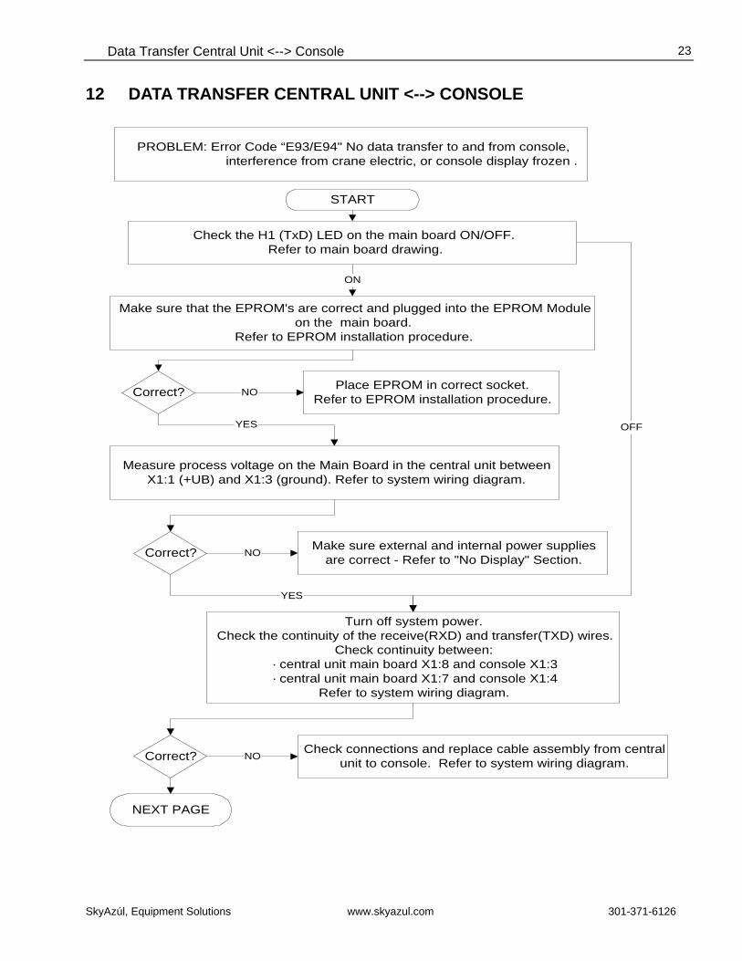
12 DATA TRANSFER CENTRAL UNIT <--> CONSOLE
Measure process voltage on the Main Board in the central unit betweenX1:1 (+UB) and X1:3 (ground). Refer to system wiring diagram.
PROBLEM: Error Code “E93/E94" No data transfer to and from console, interference from crane electric, or console display frozen .
Make sure that the EPROM's are correct and plugged into the EPROM Moduleon the main board.
Refer to EPROM installation procedure.
Place EPROM in correct socket.Refer to EPROM installation procedure.
Make sure external and internal power suppliesare correct - Refer to "No Display" Section.
NEXT PAGE
Correct?
Correct?
START
NO
YES
NO
Turn off system power.Check the continuity of the receive(RXD) and transfer(TXD) wires.
Check continuity between:· central unit main board X1:8 and console X1:3· central unit main board X1:7 and console X1:4
Refer to system wiring diagram.
YES
Correct? NOCheck connections and replace cable assembly from central
unit to console. Refer to system wiring diagram.
Check the H1 (TxD) LED on the main board ON/OFF. Refer to main board drawing.
ON
OFF
Service Manual DS 160
SkyAzúl, Equipment Solutions www.skyazul.com 301-371-6126
24
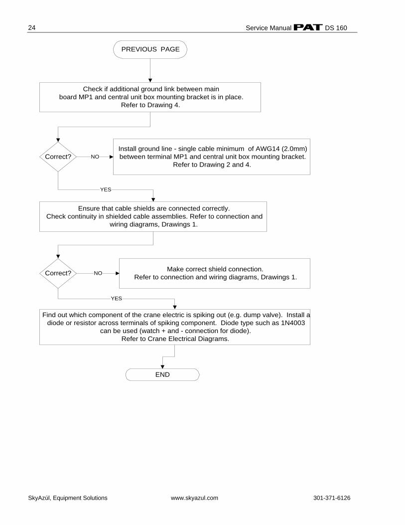
Find out which component of the crane electric is spiking out (e.g. dump valve). Install adiode or resistor across terminals of spiking component. Diode type such as 1N4003
can be used (watch + and - connection for diode).Refer to Crane Electrical Diagrams.
END
Make correct shield connection.Refer to connection and wiring diagrams, Drawings 1.
Ensure that cable shields are connected correctly.Check continuity in shielded cable assemblies. Refer to connection and
wiring diagrams, Drawings 1.
Install ground line - single cable minimum of AWG14 (2.0mm)between terminal MP1 and central unit box mounting bracket.
Refer to Drawing 2 and 4.
Check if additional ground link between mainboard MP1 and central unit box mounting bracket is in place.
Refer to Drawing 4.
PREVIOUS PAGE
Correct? NO
YES
NOCorrect?
YES
Procedures
SkyAzúl, Equipment Solutions www.skyazul.com 301-371-6126
25
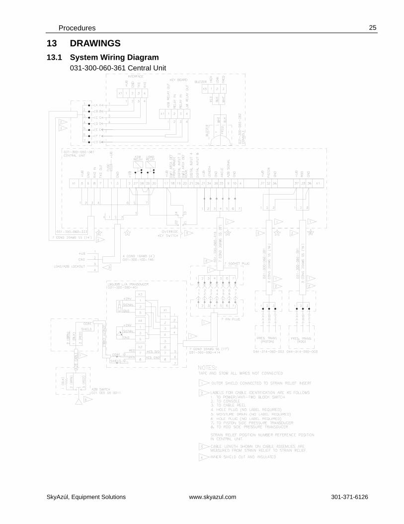
13 DRAWINGS 13.1 System Wiring Diagram
031-300-060-361 Central Unit
Service Manual DS 160
SkyAzúl, Equipment Solutions www.skyazul.com 301-371-6126
26
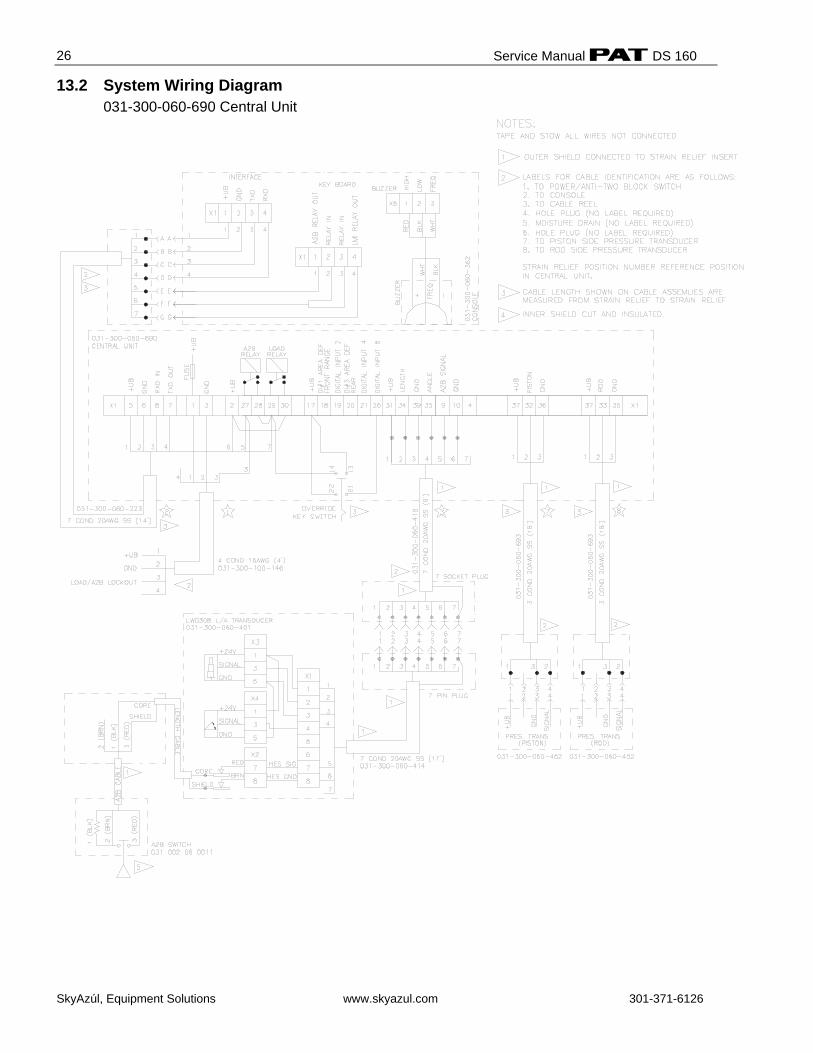
13.2 System Wiring Diagram 031-300-060-690 Central Unit
Procedures
SkyAzúl, Equipment Solutions www.skyazul.com 301-371-6126
27
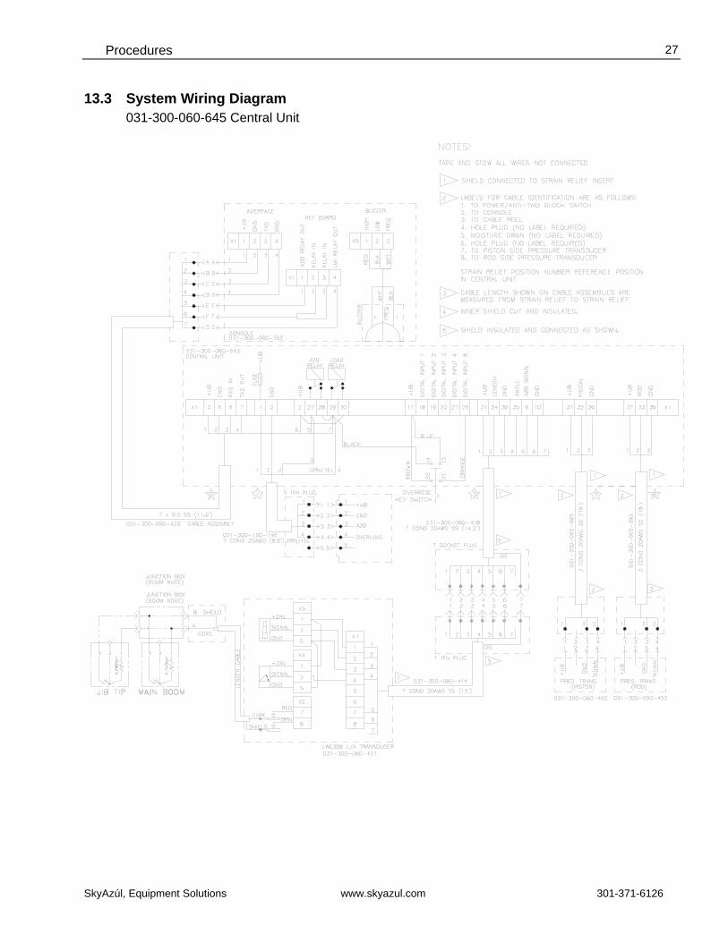
13.3 System Wiring Diagram 031-300-060-645 Central Unit
Service Manual DS 160
SkyAzúl, Equipment Solutions www.skyazul.com 301-371-6126
28
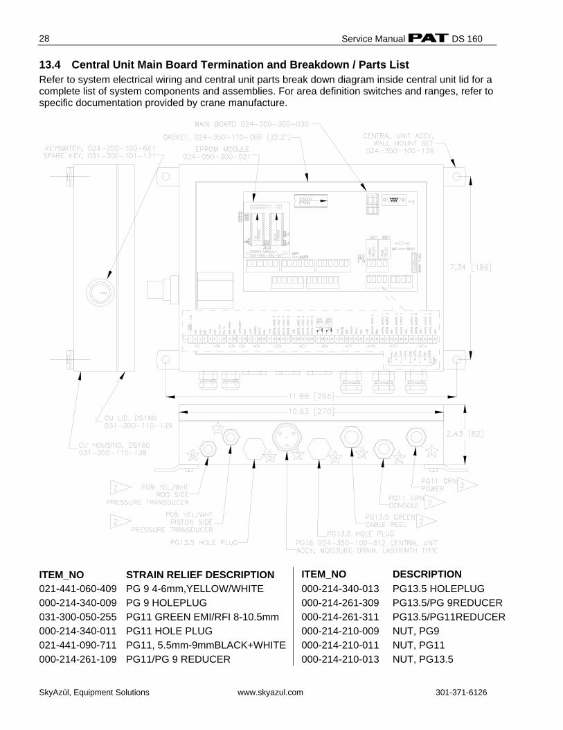
13.4 Central Unit Main Board Termination and Breakdown / Parts List Refer to system electrical wiring and central unit parts break down diagram inside central unit lid for a complete list of system components and assemblies. For area definition switches and ranges, refer to specific documentation provided by crane manufacture.
ITEM_NO STRAIN RELIEF DESCRIPTION ITEM_NO DESCRIPTION 021-441-060-409 PG 9 4-6mm,YELLOW/WHITE 000-214-340-013 PG13.5 HOLEPLUG 000-214-340-009 PG 9 HOLEPLUG 000-214-261-309 PG13.5/PG 9REDUCER 031-300-050-255 PG11 GREEN EMI/RFI 8-10.5mm 000-214-261-311 PG13.5/PG11REDUCER 000-214-340-011 PG11 HOLE PLUG 000-214-210-009 NUT, PG9 021-441-090-711 PG11, 5.5mm-9mmBLACK+WHITE 000-214-210-011 NUT, PG11 000-214-261-109 PG11/PG 9 REDUCER 000-214-210-013 NUT, PG13.5
Procedures
SkyAzúl, Equipment Solutions www.skyazul.com 301-371-6126
29
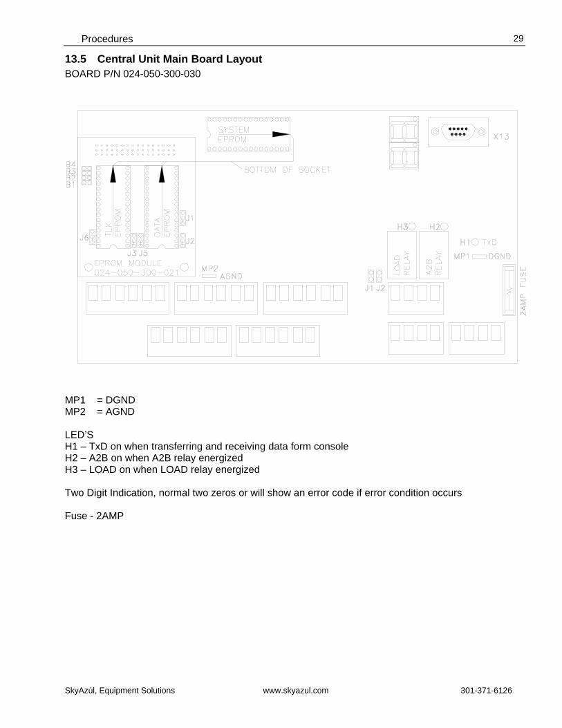
13.5 Central Unit Main Board Layout BOARD P/N 024-050-300-030
MP1 = DGND MP2 = AGND LED’S H1 – TxD on when transferring and receiving data form console H2 – A2B on when A2B relay energized H3 – LOAD on when LOAD relay energized Two Digit Indication, normal two zeros or will show an error code if error condition occurs Fuse - 2AMP

Service Manual DS 160
SkyAzúl, Equipment Solutions www.skyazul.com 301-371-6126
30
13.6 Console DS160/0005 / Parts List Part Number 031-300-060-362 (Refer to system wiring diagram for 050-160-060-005 console wiring connections to central unit) NO. PART NO. QTY DESCRIPTION 01 050-160-120-005 1 DECAL, DS160/5 FRONT FOIL 02 031-300-060-382 1 MOUNTING ARM, RAM MOUNT B-101 W/ 1” BALL 03 050-000-100-267 1 INDICATOR, DISPLAY DS160/0005 04 050-050-300-030 1 MAIN BOARD, D160/0005 05 031-300-050-223 1 FUSE, 2 AMP AUTO 06 050-050-300-036 1 KEYBOARD, DS160 CONSOLE /0005 07 031-300-100-391 1 CONNECTOR, 7-PIN RECEPTACLE 08 024-350-100-312 1 MOISTURE DRAINAGE PLUG 09 050-000-100-274 1 ALARM, DS160 CONSOLE /0005 IP65 W/ CABLE 10 050-160-100-005 1 HOUSING, COMPLETE DS160/0005 W/ DECAL
1 2
3 4
5
6 7 8 9
10 10
Procedures
SkyAzúl, Equipment Solutions www.skyazul.com 301-371-6126
31
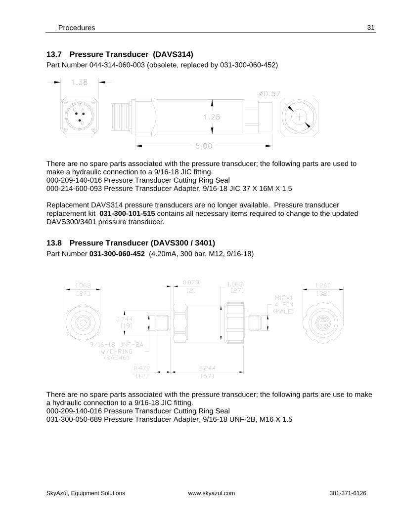
13.7 Pressure Transducer (DAVS314) Part Number 044-314-060-003 (obsolete, replaced by 031-300-060-452)
There are no spare parts associated with the pressure transducer; the following parts are used to make a hydraulic connection to a 9/16-18 JIC fitting. 000-209-140-016 Pressure Transducer Cutting Ring Seal 000-214-600-093 Pressure Transducer Adapter, 9/16-18 JIC 37 X 16M X 1.5 Replacement DAVS314 pressure transducers are no longer available. Pressure transducer replacement kit 031-300-101-515 contains all necessary items required to change to the updated DAVS300/3401 pressure transducer.
13.8 Pressure Transducer (DAVS300 / 3401) Part Number 031-300-060-452 (4.20mA, 300 bar, M12, 9/16-18) There are no spare parts associated with the pressure transducer; the following parts are use to make a hydraulic connection to a 9/16-18 JIC fitting. 000-209-140-016 Pressure Transducer Cutting Ring Seal 031-300-050-689 Pressure Transducer Adapter, 9/16-18 UNF-2B, M16 X 1.5
Service Manual DS 160
SkyAzúl, Equipment Solutions www.skyazul.com 301-371-6126
32
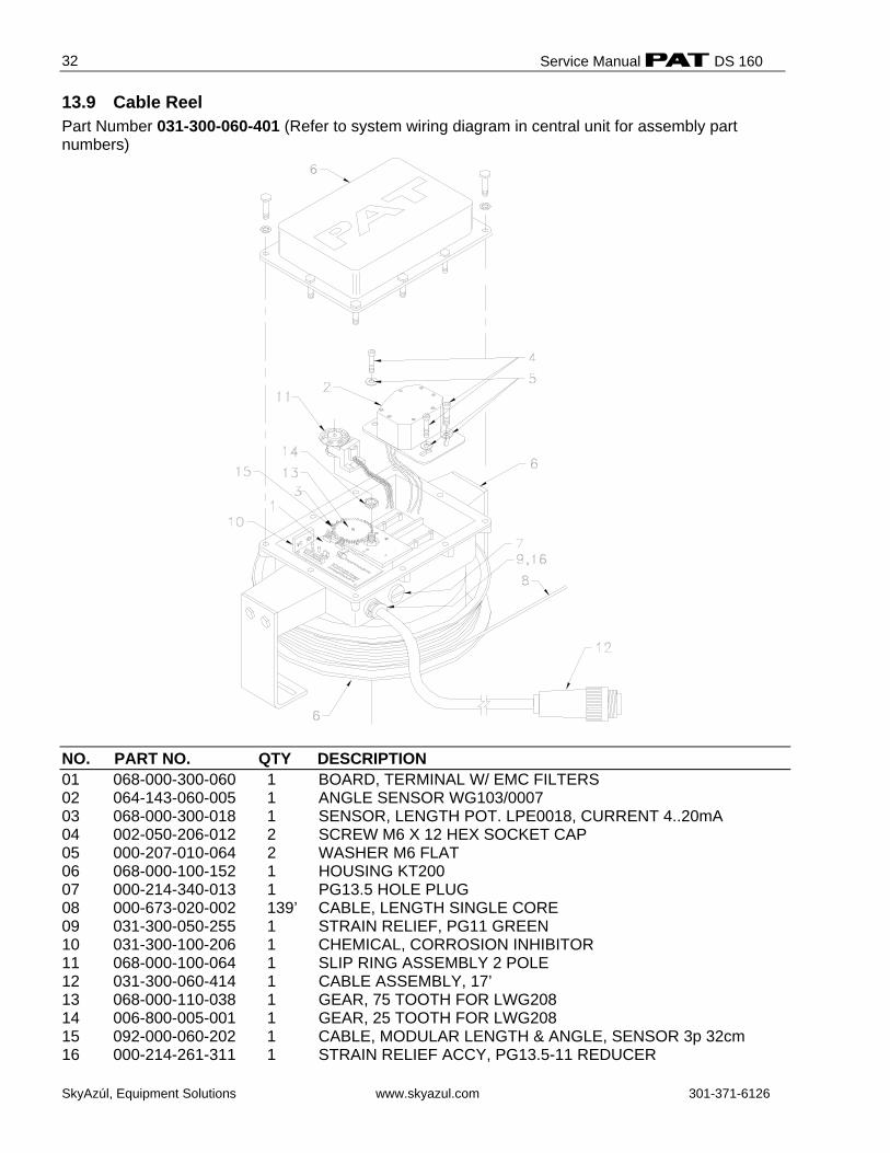
13.9 Cable Reel Part Number 031-300-060-401 (Refer to system wiring diagram in central unit for assembly part numbers)
NO. PART NO. QTY DESCRIPTION 01 068-000-300-060 1 BOARD, TERMINAL W/ EMC FILTERS 02 064-143-060-005 1 ANGLE SENSOR WG103/0007 03 068-000-300-018 1 SENSOR, LENGTH POT. LPE0018, CURRENT 4..20mA 04 002-050-206-012 2 SCREW M6 X 12 HEX SOCKET CAP 05 000-207-010-064 2 WASHER M6 FLAT 06 068-000-100-152 1 HOUSING KT200 07 000-214-340-013 1 PG13.5 HOLE PLUG 08 000-673-020-002 139’ CABLE, LENGTH SINGLE CORE 09 031-300-050-255 1 STRAIN RELIEF, PG11 GREEN 10 031-300-100-206 1 CHEMICAL, CORROSION INHIBITOR 11 068-000-100-064 1 SLIP RING ASSEMBLY 2 POLE 12 031-300-060-414 1 CABLE ASSEMBLY, 17’ 13 068-000-110-038 1 GEAR, 75 TOOTH FOR LWG208 14 006-800-005-001 1 GEAR, 25 TOOTH FOR LWG208 15 092-000-060-202 1 CABLE, MODULAR LENGTH & ANGLE, SENSOR 3p 32cm 16 000-214-261-311 1 STRAIN RELIEF ACCY, PG13.5-11 REDUCER
Procedures
SkyAzúl, Equipment Solutions www.skyazul.com 301-371-6126
33
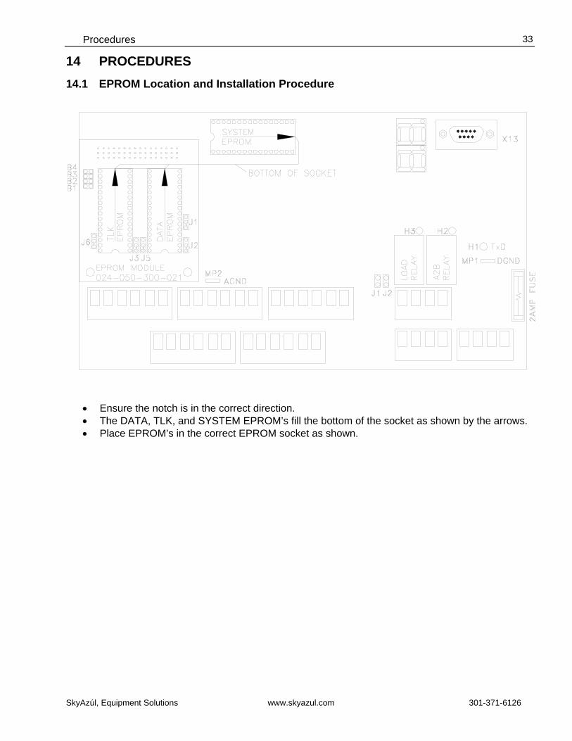
14 PROCEDURES 14.1 EPROM Location and Installation Procedure
• Ensure the notch is in the correct direction. • The DATA, TLK, and SYSTEM EPROM’s fill the bottom of the socket as shown by the arrows. • Place EPROM’s in the correct EPROM socket as shown.
Service Manual DS 160
SkyAzúl, Equipment Solutions www.skyazul.com 301-371-6126
34
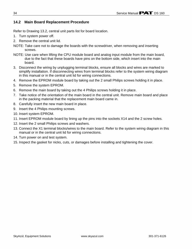
14.2 Main Board Replacement Procedure Refer to Drawing 13.2, central unit parts list for board location. 1. Turn system power off. 2. Remove the central unit lid. NOTE: Take care not to damage the boards with the screwdriver, when removing and inserting
screws. NOTE: Use care when lifting the CPU module board and analog input module from the main board,
due to the fact that these boards have pins on the bottom side, which insert into the main board.
3. Disconnect the wiring by unplugging terminal blocks, ensure all blocks and wires are marked to simplify installation. If disconnecting wires from terminal blocks refer to the system wiring diagram in this manual or in the central unit lid for wiring connections.
4. Remove the EPROM module board by taking out the 2 small Philips screws holding it in place. 5. Remove the system EPROM. 6. Remove the main board by taking out the 4 Philips screws holding it in place. 7. Take notice of the orientation of the main board in the central unit. Remove main board and place
in the packing material that the replacement main board came in. 8. Carefully insert the new main board in place. 9. Insert the 4 Philips mounting screws. 10. Insert system EPROM. 11. Insert EPROM module board by lining up the pins into the sockets X14 and the 2 screw holes. 12. Insert the 2 small Philips screws and washers. 13. Connect the X1 terminal blocks/wires to the main board. Refer to the system wiring diagram in this
manual or in the central unit lid for wiring connections. 14. Turn power on and test system. 15. Inspect the gasket for nicks, cuts, or damages before installing and tightening the cover.
Procedures
SkyAzúl, Equipment Solutions www.skyazul.com 301-371-6126
35
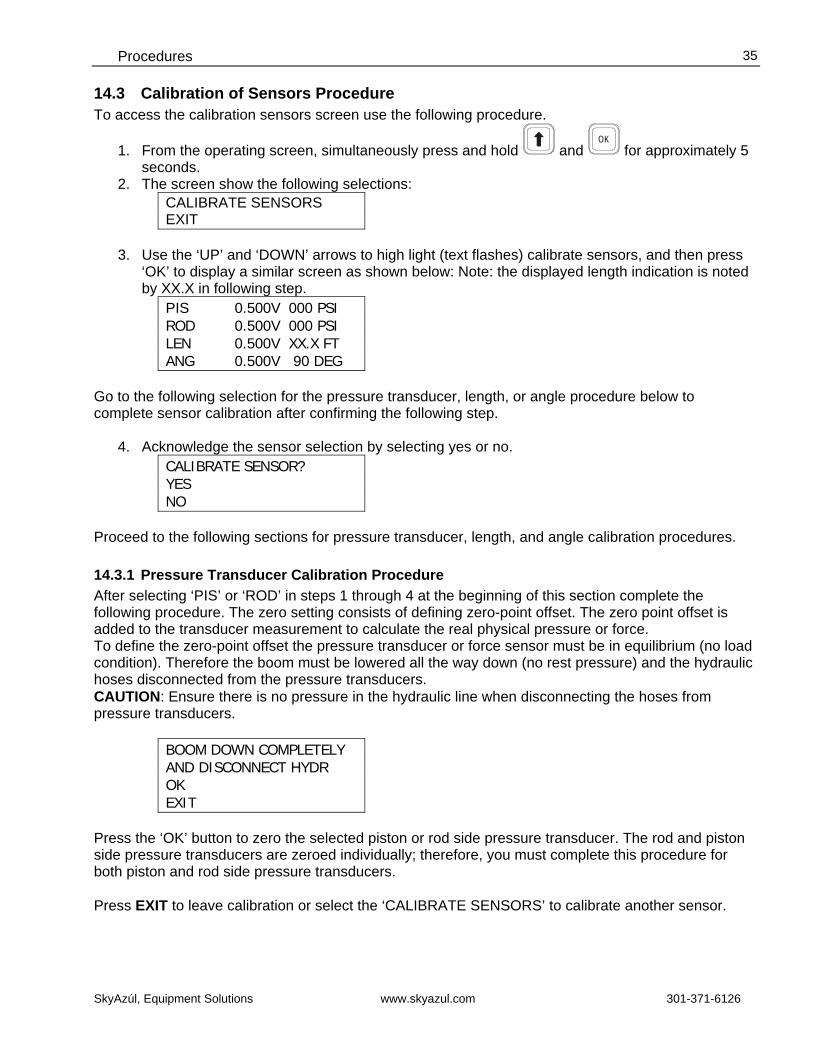
14.3 Calibration of Sensors Procedure To access the calibration sensors screen use the following procedure.
1. From the operating screen, simultaneously press and hold and OK
for approximately 5 seconds.
2. The screen show the following selections: CALIBRATE SENSORS EXIT
3. Use the ‘UP’ and ‘DOWN’ arrows to high light (text flashes) calibrate sensors, and then press ‘OK’ to display a similar screen as shown below: Note: the displayed length indication is noted by XX.X in following step.
PIS 0.500V 000 PSI ROD 0.500V 000 PSI LEN 0.500V XX.X FT ANG 0.500V 90 DEG
Go to the following selection for the pressure transducer, length, or angle procedure below to complete sensor calibration after confirming the following step.
4. Acknowledge the sensor selection by selecting yes or no. CALIBRATE SENSOR? YES NO
Proceed to the following sections for pressure transducer, length, and angle calibration procedures. 14.3.1 Pressure Transducer Calibration Procedure After selecting ‘PIS’ or ‘ROD’ in steps 1 through 4 at the beginning of this section complete the following procedure. The zero setting consists of defining zero-point offset. The zero point offset is added to the transducer measurement to calculate the real physical pressure or force. To define the zero-point offset the pressure transducer or force sensor must be in equilibrium (no load condition). Therefore the boom must be lowered all the way down (no rest pressure) and the hydraulic hoses disconnected from the pressure transducers. CAUTION: Ensure there is no pressure in the hydraulic line when disconnecting the hoses from pressure transducers.
BOOM DOWN COMPLETELY AND DISCONNECT HYDR OK EXIT
Press the ‘OK’ button to zero the selected piston or rod side pressure transducer. The rod and piston side pressure transducers are zeroed individually; therefore, you must complete this procedure for both piston and rod side pressure transducers. Press EXIT to leave calibration or select the ‘CALIBRATE SENSORS’ to calibrate another sensor.
Service Manual DS 160
SkyAzúl, Equipment Solutions www.skyazul.com 301-371-6126
36
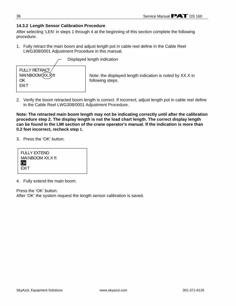
FULLY RETRACT MAINBOOM XX.X ft OK EXIT
Displayed length indication
14.3.2 Length Sensor Calibration Procedure After selecting ‘LEN’ in steps 1 through 4 at the beginning of this section complete the following procedure. 1. Fully retract the main boom and adjust length pot in cable reel define in the Cable Reel
LWG308/0001 Adjustment Procedure in this manual.
Note: the displayed length indication is noted by XX.X in following steps.
2. Verify the boom retracted boom length is correct. If incorrect, adjust length pot in cable reel define
in the Cable Reel LWG308/0001 Adjustment Procedure. Note: The retracted main boom length may not be indicating correctly until after the calibration procedure step 2. The display length is not the load chart length. The correct display length can be found in the LMI section of the crane operator's manual. If the indication is more than 0.2 feet incorrect, recheck step 1. 3. Press the ‘OK’ button.
4. Fully extend the main boom. Press the ‘OK’ button. After ‘OK’ the system request the length sensor calibration is saved.
FULLY EXTEND MAINBOOM XX.X ft OK EXIT
Procedures
SkyAzúl, Equipment Solutions www.skyazul.com 301-371-6126
37
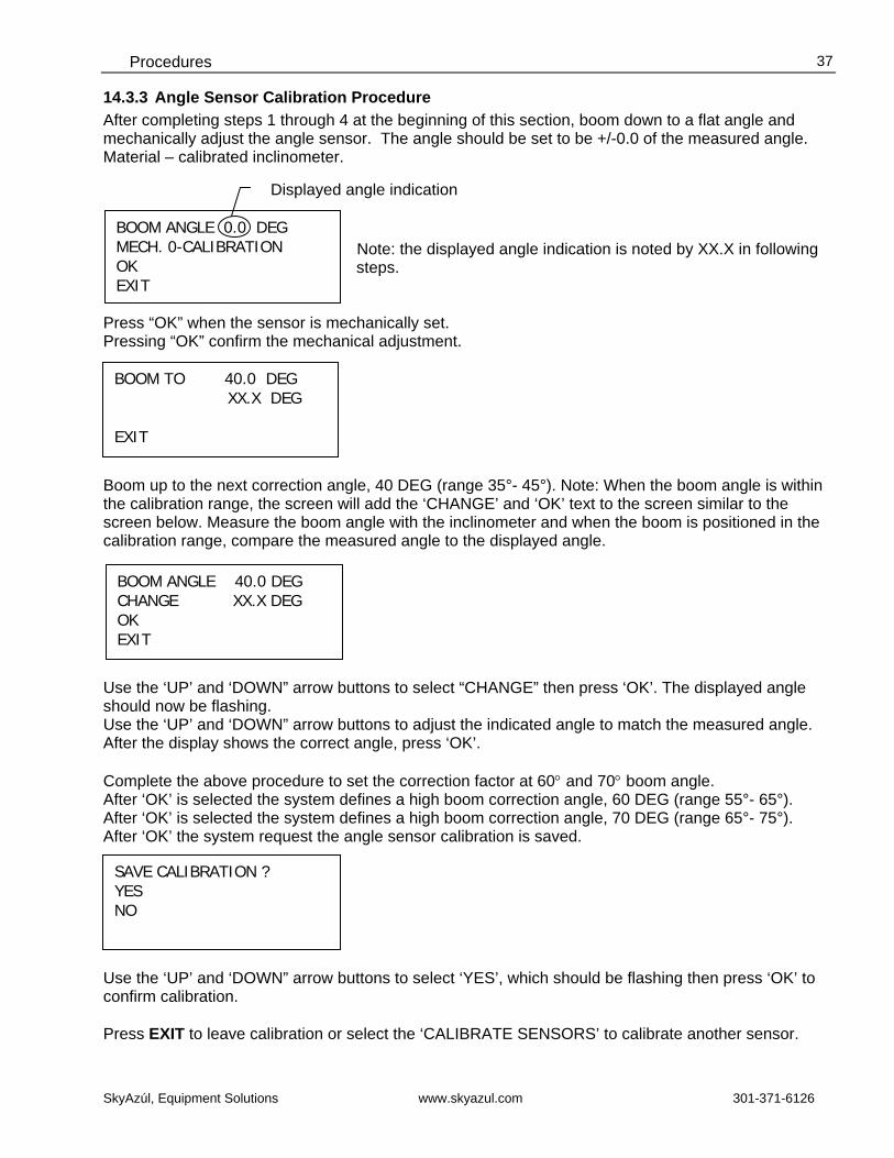
14.3.3 Angle Sensor Calibration Procedure After completing steps 1 through 4 at the beginning of this section, boom down to a flat angle and mechanically adjust the angle sensor. The angle should be set to be +/-0.0 of the measured angle. Material – calibrated inclinometer.
Note: the displayed angle indication is noted by XX.X in following steps.
Press “OK” when the sensor is mechanically set. Pressing “OK” confirm the mechanical adjustment.
Boom up to the next correction angle, 40 DEG (range 35°- 45°). Note: When the boom angle is within the calibration range, the screen will add the ‘CHANGE’ and ‘OK’ text to the screen similar to the screen below. Measure the boom angle with the inclinometer and when the boom is positioned in the calibration range, compare the measured angle to the displayed angle.
Use the ‘UP’ and ‘DOWN” arrow buttons to select “CHANGE” then press ‘OK’. The displayed angle should now be flashing. Use the ‘UP’ and ‘DOWN” arrow buttons to adjust the indicated angle to match the measured angle. After the display shows the correct angle, press ‘OK’. Complete the above procedure to set the correction factor at 60° and 70° boom angle. After ‘OK’ is selected the system defines a high boom correction angle, 60 DEG (range 55°- 65°). After ‘OK’ is selected the system defines a high boom correction angle, 70 DEG (range 65°- 75°). After ‘OK’ the system request the angle sensor calibration is saved.
Use the ‘UP’ and ‘DOWN” arrow buttons to select ‘YES’, which should be flashing then press ‘OK’ to confirm calibration. Press EXIT to leave calibration or select the ‘CALIBRATE SENSORS’ to calibrate another sensor.
BOOM TO 40.0 DEG XX.X DEG EXIT
BOOM ANGLE 40.0 DEG CHANGE XX.X DEG OK EXIT
SAVE CALIBRATION ? YES NO
BOOM ANGLE 0.0 DEG MECH. 0-CALIBRATION OK EXIT
Displayed angle indication
Service Manual DS 160
SkyAzúl, Equipment Solutions www.skyazul.com 301-371-6126
38
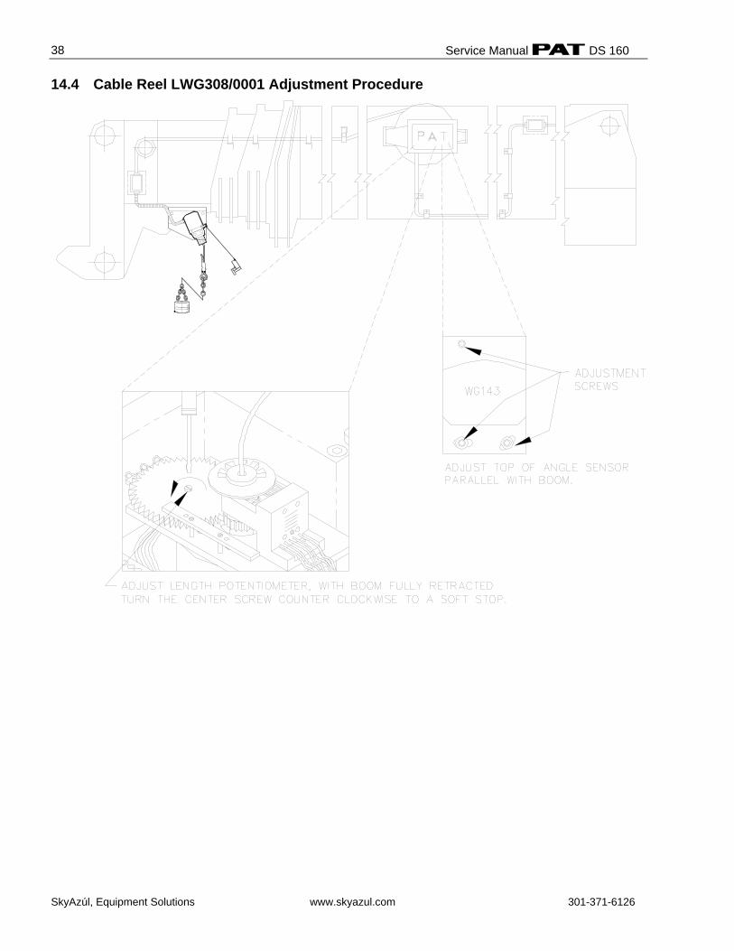
14.4 Cable Reel LWG308/0001 Adjustment Procedure

Procedures
SkyAzúl, Equipment Solutions www.skyazul.com 301-371-6126
39
14.5 Cable Reel Length Cable Replacement Procedure Replace length cable using the following procedure: Refer to system electrical wiring diagram and cable reel - parts list
1. Cut old cable at cable drum. 2. Disconnect damaged length cable from junction box at the boom nose. 3. Open cable reel cover and disconnect wiring from terminal block. Pull 7 conductor cable out of
strain relief. Note: Mark wires to make connection simpler after cable installation. 4. Remove cable reel from mounting brackets. 5. Remove damaged length cable, which is mounted to the slip rings in the cable reel, from slip ring
terminal. 6. On the backside of the cable reel, open the strain relief attached to the axle in the center of the
drum. Pull existing length cable out of the cable reel. 7. Pull new length cable through the hole, pipe and strain relief and push it through the axle of the
reeling drum. Tighten new strain relief to ensure sealing. 8. Reconnect the length cable to the slip ring. 9. Remount cable reel to the boom. 10. Turn reeling drum clockwise to spool the new cable neatly onto the drum. 11. Set pre-load on cable reel by turning the drum counter-clockwise 5 to 8 turns. 12. Run the new length cable through the cable guides and wrap the length cable around the boom
tip anchor pin (4 or 5 wraps) and secure with tie wraps. Leave enough length cable to connect into the boom tip junction box.
13. Connect the length cable into the boom tip junction box. 14. Reset length potentiometer in length angle transducer (screw is located in center of white gear);
with boom fully retracted, turn potentiometer carefully counter-clockwise until it stops. Recheck length and angle display. Refer to Cable Reel LWG308/0001 Adjustment Procedure.
Service Manual DS 160
SkyAzúl, Equipment Solutions www.skyazul.com 301-371-6126
40
15 TROUBLESHOOTING MOISTURE The PAT DS 160 LMI contains electronic components in various locations, such as central unit, sensors, junction boxes etc. These internal components cannot be designed to withstand exposure to moisture over a longer period of time. For this reason, the housings of the components are water protected according to IP 65. If you find water or moisture inside any of the housings, the source for the water ingress has to be detected and corrected to ensure proper operation. There are two major possibilities for the occurrence of excessive moisture inside an enclosure: 1) Water ingress 2) Condensation This outline gives instructions for detecting the cause for excessive moisture by using simple troubleshooting methods and how to prevent the moisture ingress from happening again. 15.1.1 Water Ingress There are 6 possibilities for water to enter an enclosure: 1) Spray Cleaning 2) Missing / Loose Screws 3) Bent Lid 4) Defective Gasket 5) Loose Strain Relieves 6) Water Entry Through External Cabling It is possible to find out the source of water ingress by going through the following steps and ruling out one possibility after the other until the cause is identified: 1) Spray Cleaning
The enclosures used for the PAT DS 160 system are water protected to IP 65. This means protection against the environment, such as rain. However, through the use of spray cleaner at short distances, it is possible to force water through the gasket or strain relieves. For this reason, avoid spraying any components from short distances with spray cleaners. Convey this fact to any member of a maintenance crew.
2) Missing / Loose Screws
All screws have to be present and to be equally tight to ensure water protection of the enclosure. If there are screws missing, replace them. If no screw is missing, check the tightness. If any were loose, then open all screws and then re-tighten them equally.
3) Bent Lid
An enclosure will only seal correctly if the lid is not bent. To check this, loosen all screws of the lid, take the lid off the box and visually inspect it for deflection. If the lid is bent or damaged, it needs to be replaced. Try to determine what has caused the lid to be bent and eliminate the reason for that. Order a new lid through your PAT representative.
Troubleshooting Moisture
SkyAzúl, Equipment Solutions www.skyazul.com 301-371-6126
41
4) Defective Gasket
The gasket underneath the lid seals the unit. The gasket needs to be in good condition in order to seal correctly. If the gasket is torn, brittle or severely bent, it needs to be replaced. Order a new gasket through your PAT representative.
5) Loose Strain Relieves
The strain relieves allow cabling to enter the box without allowing water to enter it. The strain relieves have to be correctly tightened in order to do this. Check the tightness by taking the external cable into one hand and carefully trying to turn it. If the internal wires turn with the outer cable, the strain relief is loose. Get a new grommet (insert) through your PAT representative and replace the existing one with the new one. Tighten the strain relief correctly. Note: Whenever a strain relief is opened, i.e. to replace a cable, a new grommet needs to be used. Never re-use any grommet or the strain relief will not seal properly!
6) Water Entry Through External Cabling
Even with a tight strain relief, water may still enter the box through the inside of the cable. In this case, you have to find out why and where water enters the cable. Look for damages to the cable itself and inspect the opposite side of the cable. In example, if the cable comes from a connector that is full of water, the water will run through the inside of the cable and fill up the central unit, too.
15.1.2 Condensation In a climate with high humidity and rapidly changing temperatures, condensation can happen inside any enclosure, usually the larger the volume of the box, the more likely. In this case, water drops build up on the inner components when humid air is trapped inside the box. With condensation, water tightness is not a problem – the box is sealed just fine, which is what prevents the trapped air from exiting the box. There are two ways to deal with condensation:
1. If the volume is very small, a desiccant bag might be able to soak up the air’s humidity. 2. If the effect is more severe, the only way to get rid of this effect is then to give the box the
ability to breath without sacrificing its water tightness. Contact your PAT representative for breathing elements to than can be added to the box and will help to reduce the effects of humid climates.
Service Manual DS 160
SkyAzúl, Equipment Solutions www.skyazul.com 301-371-6126
42
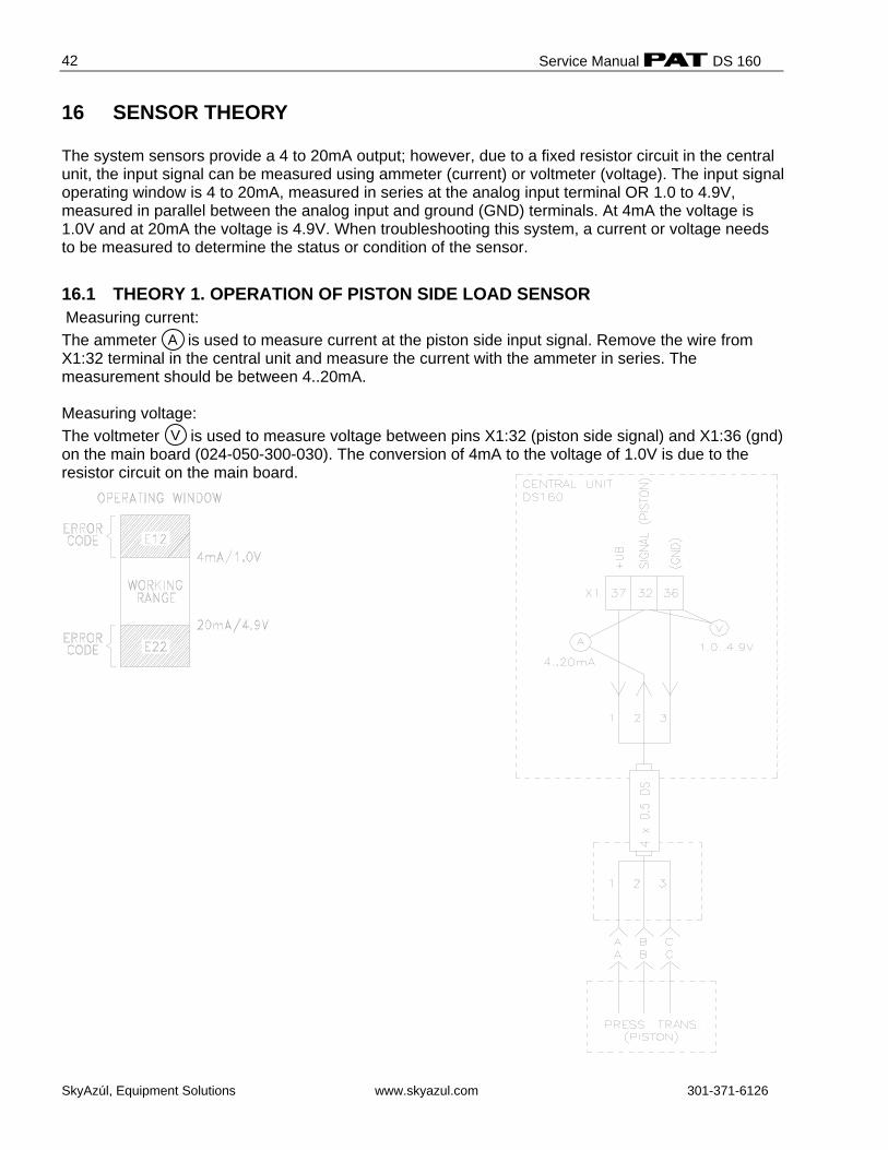
16 SENSOR THEORY The system sensors provide a 4 to 20mA output; however, due to a fixed resistor circuit in the central unit, the input signal can be measured using ammeter (current) or voltmeter (voltage). The input signal operating window is 4 to 20mA, measured in series at the analog input terminal OR 1.0 to 4.9V, measured in parallel between the analog input and ground (GND) terminals. At 4mA the voltage is 1.0V and at 20mA the voltage is 4.9V. When troubleshooting this system, a current or voltage needs to be measured to determine the status or condition of the sensor.
16.1 THEORY 1. OPERATION OF PISTON SIDE LOAD SENSOR Measuring current: The ammeter is used to measure current at the piston side input signal. Remove the wire from X1:32 terminal in the central unit and measure the current with the ammeter in series. The measurement should be between 4..20mA. Measuring voltage: The voltmeter is used to measure voltage between pins X1:32 (piston side signal) and X1:36 (gnd) on the main board (024-050-300-030). The conversion of 4mA to the voltage of 1.0V is due to the resistor circuit on the main board.
A
V
Theory
SkyAzúl, Equipment Solutions www.skyazul.com 301-371-6126
43
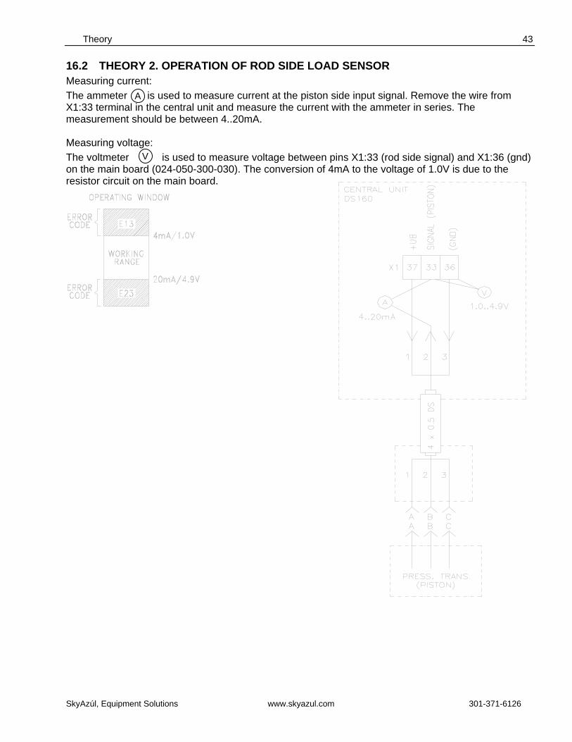
V
16.2 THEORY 2. OPERATION OF ROD SIDE LOAD SENSOR Measuring current: The ammeter is used to measure current at the piston side input signal. Remove the wire from X1:33 terminal in the central unit and measure the current with the ammeter in series. The measurement should be between 4..20mA. Measuring voltage: The voltmeter is used to measure voltage between pins X1:33 (rod side signal) and X1:36 (gnd) on the main board (024-050-300-030). The conversion of 4mA to the voltage of 1.0V is due to the resistor circuit on the main board.
A
Service Manual DS 160
SkyAzúl, Equipment Solutions www.skyazul.com 301-371-6126
44
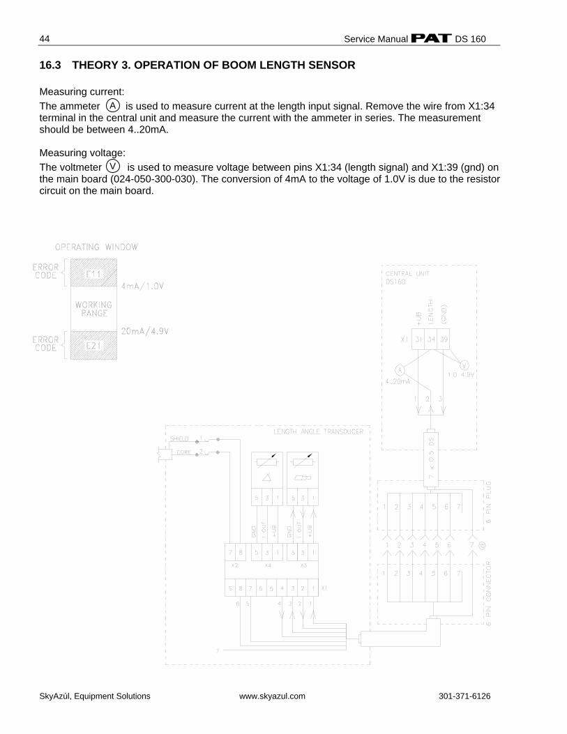
16.3 THEORY 3. OPERATION OF BOOM LENGTH SENSOR Measuring current: The ammeter is used to measure current at the length input signal. Remove the wire from X1:34 terminal in the central unit and measure the current with the ammeter in series. The measurement should be between 4..20mA. Measuring voltage: The voltmeter is used to measure voltage between pins X1:34 (length signal) and X1:39 (gnd) on the main board (024-050-300-030). The conversion of 4mA to the voltage of 1.0V is due to the resistor circuit on the main board.
A
V
Theory
SkyAzúl, Equipment Solutions www.skyazul.com 301-371-6126
45
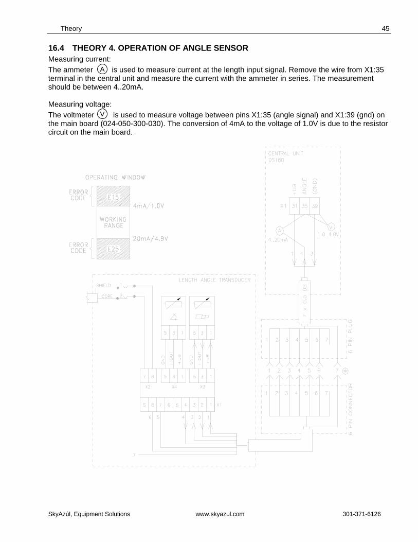
16.4 THEORY 4. OPERATION OF ANGLE SENSOR Measuring current: The ammeter is used to measure current at the length input signal. Remove the wire from X1:35 terminal in the central unit and measure the current with the ammeter in series. The measurement should be between 4..20mA. Measuring voltage: The voltmeter is used to measure voltage between pins X1:35 (angle signal) and X1:39 (gnd) on the main board (024-050-300-030). The conversion of 4mA to the voltage of 1.0V is due to the resistor circuit on the main board.
A
V
Service Manual DS 160
SkyAzúl, Equipment Solutions www.skyazul.com 301-371-6126
46
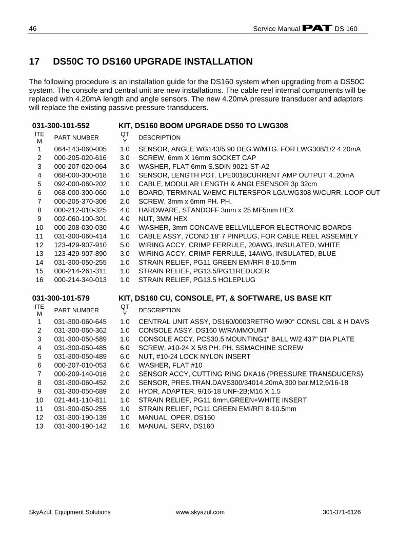
17 DS50C TO DS160 UPGRADE INSTALLATION The following procedure is an installation guide for the DS160 system when upgrading from a DS50C system. The console and central unit are new installations. The cable reel internal components will be replaced with 4.20mA length and angle sensors. The new 4.20mA pressure transducer and adaptors will replace the existing passive pressure transducers. 031-300-101-552 KIT, DS160 BOOM UPGRADE DS50 TO LWG308 ITEM PART NUMBER QT
Y DESCRIPTION
1 064-143-060-005 1.0 SENSOR, ANGLE WG143/5 90 DEG.W/MTG. FOR LWG308/1/2 4.20mA 2 000-205-020-616 3.0 SCREW, 6mm X 16mm SOCKET CAP 3 000-207-020-064 3.0 WASHER, FLAT 6mm S.SDIN 9021-ST-A2 4 068-000-300-018 1.0 SENSOR, LENGTH POT. LPE0018CURRENT AMP OUTPUT 4..20mA 5 092-000-060-202 1.0 CABLE, MODULAR LENGTH & ANGLESENSOR 3p 32cm 6 068-000-300-060 1.0 BOARD, TERMINAL W/EMC FILTERSFOR LG/LWG308 W/CURR. LOOP OUT 7 000-205-370-306 2.0 SCREW, 3mm x 6mm PH. PH. 8 000-212-010-325 4.0 HARDWARE, STANDOFF 3mm x 25 MF5mm HEX 9 002-060-100-301 4.0 NUT, 3MM HEX 10 000-208-030-030 4.0 WASHER, 3mm CONCAVE BELLVILLEFOR ELECTRONIC BOARDS 11 031-300-060-414 1.0 CABLE ASSY, 7COND 18' 7 PINPLUG, FOR CABLE REEL ASSEMBLY 12 123-429-907-910 5.0 WIRING ACCY, CRIMP FERRULE, 20AWG, INSULATED, WHITE 13 123-429-907-890 3.0 WIRING ACCY, CRIMP FERRULE, 14AWG, INSULATED, BLUE 14 031-300-050-255 1.0 STRAIN RELIEF, PG11 GREEN EMI/RFI 8-10.5mm 15 000-214-261-311 1.0 STRAIN RELIEF, PG13.5/PG11REDUCER 16 000-214-340-013 1.0 STRAIN RELIEF, PG13.5 HOLEPLUG
031-300-101-579 KIT, DS160 CU, CONSOLE, PT, & SOFTWARE, US BASE KIT ITEM PART NUMBER QT
Y DESCRIPTION
1 031-300-060-645 1.0 CENTRAL UNIT ASSY, DS160/0003RETRO W/90° CONSL CBL & H DAVS 2 031-300-060-362 1.0 CONSOLE ASSY, DS160 W/RAMMOUNT 3 031-300-050-589 1.0 CONSOLE ACCY, PCS30.5 MOUNTING1" BALL W/2.437" DIA PLATE 4 031-300-050-485 6.0 SCREW, #10-24 X 5/8 PH. PH. SSMACHINE SCREW 5 031-300-050-489 6.0 NUT, #10-24 LOCK NYLON INSERT 6 000-207-010-053 6.0 WASHER, FLAT #10 7 000-209-140-016 2.0 SENSOR ACCY, CUTTING RING DKA16 (PRESSURE TRANSDUCERS) 8 031-300-060-452 2.0 SENSOR, PRES.TRAN.DAVS300/34014.20mA,300 bar,M12,9/16-18 9 031-300-050-689 2.0 HYDR, ADAPTER, 9/16-18 UNF-2B;M16 X 1.5 10 021-441-110-811 1.0 STRAIN RELIEF, PG11 6mm,GREEN+WHITE INSERT 11 031-300-050-255 1.0 STRAIN RELIEF, PG11 GREEN EMI/RFI 8-10.5mm 12 031-300-190-139 1.0 MANUAL, OPER, DS160 13 031-300-190-142 1.0 MANUAL, SERV, DS160
DS160 Upgrade Installation
SkyAzúl, Equipment Solutions www.skyazul.com 301-371-6126
47
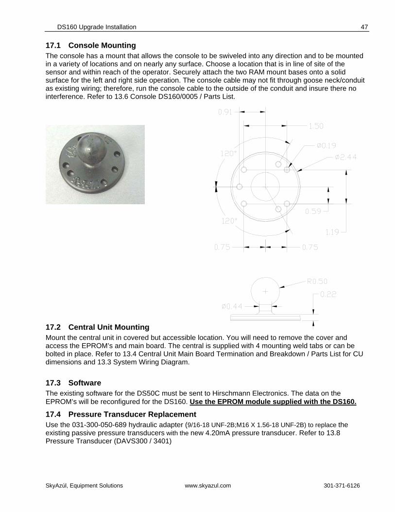
17.1 Console Mounting The console has a mount that allows the console to be swiveled into any direction and to be mounted in a variety of locations and on nearly any surface. Choose a location that is in line of site of the sensor and within reach of the operator. Securely attach the two RAM mount bases onto a solid surface for the left and right side operation. The console cable may not fit through goose neck/conduit as existing wiring; therefore, run the console cable to the outside of the conduit and insure there no interference. Refer to 13.6 Console DS160/0005 / Parts List.
17.2 Central Unit Mounting Mount the central unit in covered but accessible location. You will need to remove the cover and access the EPROM’s and main board. The central is supplied with 4 mounting weld tabs or can be bolted in place. Refer to 13.4 Central Unit Main Board Termination and Breakdown / Parts List for CU dimensions and 13.3 System Wiring Diagram.
17.3 Software The existing software for the DS50C must be sent to Hirschmann Electronics. The data on the EPROM’s will be reconfigured for the DS160. Use the EPROM module supplied with the DS160.
17.4 Pressure Transducer Replacement Use the 031-300-050-689 hydraulic adapter (9/16-18 UNF-2B;M16 X 1.56-18 UNF-2B) to replace the existing passive pressure transducers with the new 4.20mA pressure transducer. Refer to 13.8 Pressure Transducer (DAVS300 / 3401)
Service Manual DS 160
SkyAzúl, Equipment Solutions www.skyazul.com 301-371-6126
48
17.5 DS160 COMPONENT INSTALLATION PROCEDURE
1. Retract the boom fully. Refer to the manufacturer’s operator’s manual and familiarize yourself with its operation and the LMI bypass. Lower the boom to gain access to the DS 50 system.
2. Switch crane power off.
3. Remove the cable reel cover face by loosening all 10 screws. The screws should remain secured in the lid.
4. Remove all connections located at X-1, X-2, X-7 and X-8.
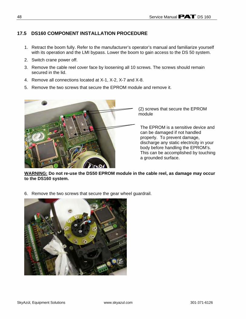
5. Remove the two screws that secure the EPROM module and remove it.
WARNING: Do not re-use the DS50 EPROM module in the cable reel, as damage may occur to the DS160 system.
6. Remove the two screws that secure the gear wheel guardrail.
(2) screws that secure the EPROM module
The EPROM is a sensitive device and can be damaged if not handled properly. To prevent damage, discharge any static electricity in your body before handling the EPROM’s. This can be accomplished by touching a grounded surface.
DS160 Upgrade Installation
SkyAzúl, Equipment Solutions www.skyazul.com 301-371-6126
49
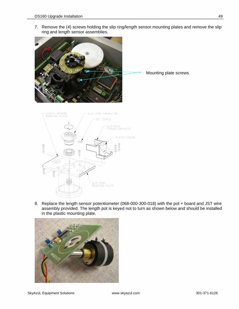
7. Remove the (4) screws holding the slip ring/length sensor mounting plates and remove the slip ring and length sensor assemblies.
8. Replace the length sensor potentiometer (068-000-300-018) with the pot + board and JST wire
assembly provided. The length pot is keyed not to turn as shown below and should be installed in the plastic mounting plate.
Mounting plate screws
Service Manual DS 160
SkyAzúl, Equipment Solutions www.skyazul.com 301-371-6126
50
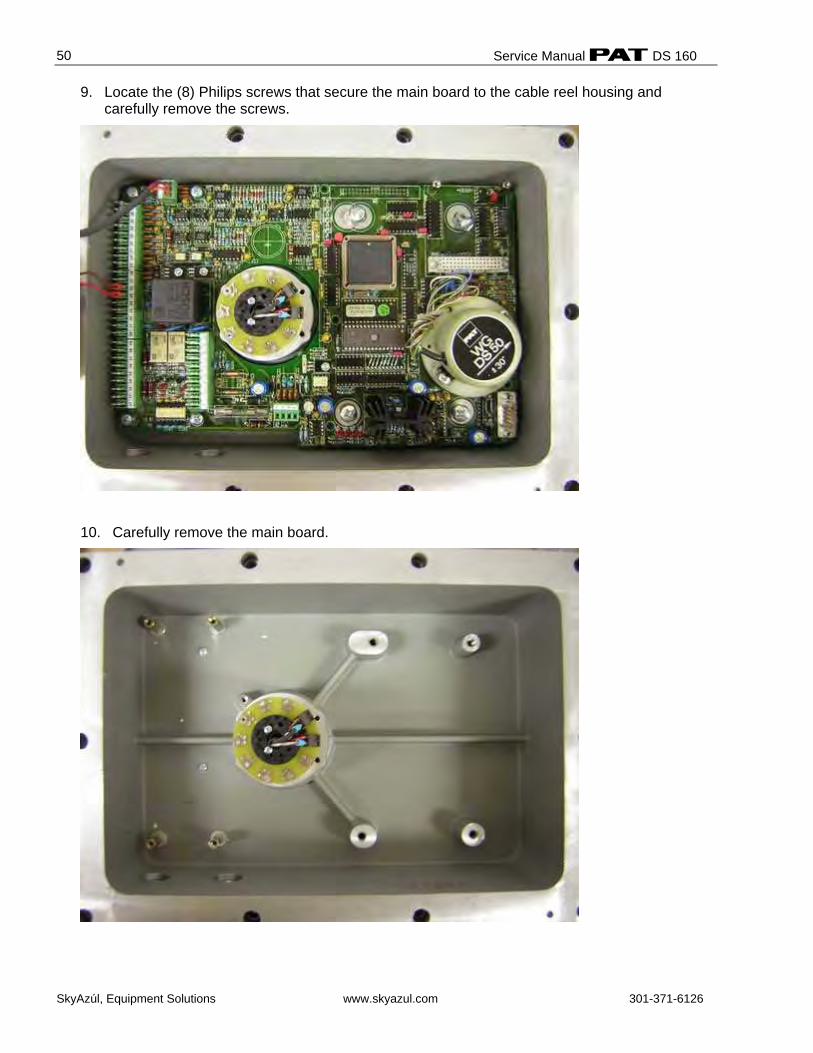
9. Locate the (8) Philips screws that secure the main board to the cable reel housing and carefully remove the screws.
10. Carefully remove the main board.
DS160 Upgrade Installation
SkyAzúl, Equipment Solutions www.skyazul.com 301-371-6126
51
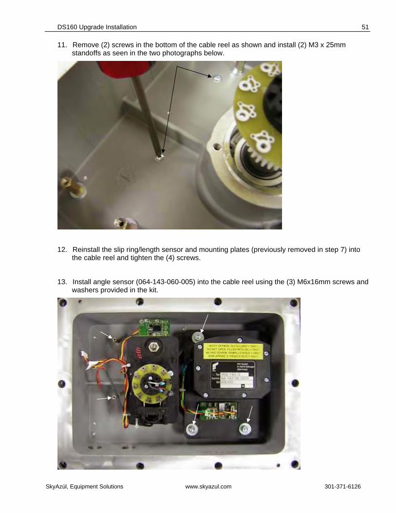
11. Remove (2) screws in the bottom of the cable reel as shown and install (2) M3 x 25mm standoffs as seen in the two photographs below.
12. Reinstall the slip ring/length sensor and mounting plates (previously removed in step 7) into the cable reel and tighten the (4) screws.
13. Install angle sensor (064-143-060-005) into the cable reel using the (3) M6x16mm screws and washers provided in the kit.
Service Manual DS 160
SkyAzúl, Equipment Solutions www.skyazul.com 301-371-6126
52
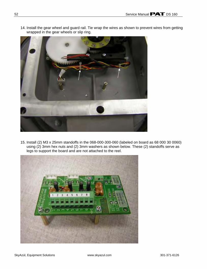
14. Install the gear wheel and guard rail. Tie wrap the wires as shown to prevent wires from getting wrapped in the gear wheels or slip ring.
15. Install (2) M3 x 25mm standoffs in the 068-000-300-060 (labeled on board as 68 000 30 0060) using (2) 3mm hex nuts and (2) 3mm washers as shown below. These (2) standoffs serve as legs to support the board and are not attached to the reel.
DS160 Upgrade Installation
SkyAzúl, Equipment Solutions www.skyazul.com 301-371-6126
53
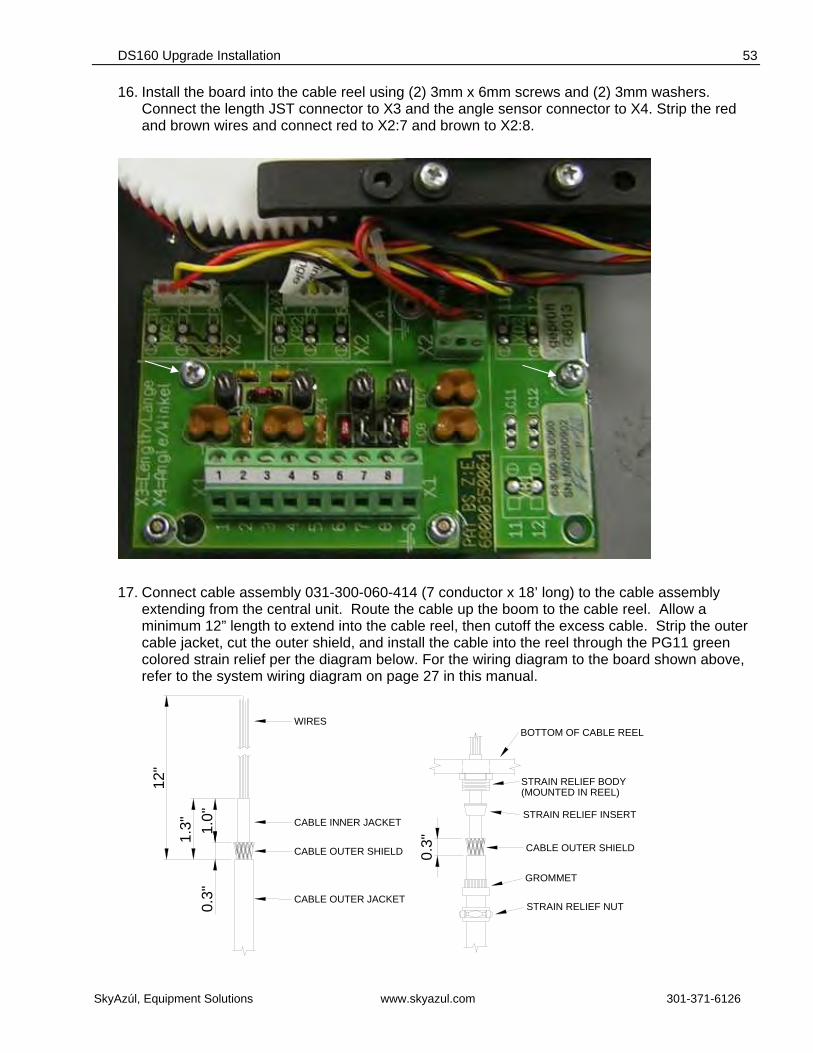
16. Install the board into the cable reel using (2) 3mm x 6mm screws and (2) 3mm washers. Connect the length JST connector to X3 and the angle sensor connector to X4. Strip the red and brown wires and connect red to X2:7 and brown to X2:8.
17. Connect cable assembly 031-300-060-414 (7 conductor x 18’ long) to the cable assembly extending from the central unit. Route the cable up the boom to the cable reel. Allow a minimum 12” length to extend into the cable reel, then cutoff the excess cable. Strip the outer cable jacket, cut the outer shield, and install the cable into the reel through the PG11 green colored strain relief per the diagram below. For the wiring diagram to the board shown above, refer to the system wiring diagram on page 27 in this manual.
0.3" CABLE OUTER JACKET
12"
1.0"
1.3" CABLE INNER JACKET
WIRES
CABLE OUTER SHIELD
GROMMET
STRAIN RELIEF NUT
STRAIN RELIEF INSERT
(MOUNTED IN REEL)STRAIN RELIEF BODY
BOTTOM OF CABLE REEL
CABLE OUTER SHIELD0.3"
Service Manual DS 160
SkyAzúl, Equipment Solutions www.skyazul.com 301-371-6126
54
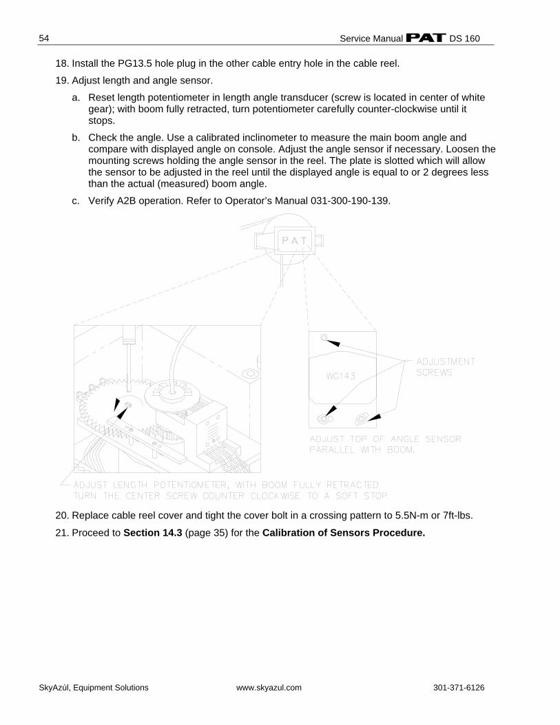
18. Install the PG13.5 hole plug in the other cable entry hole in the cable reel.
19. Adjust length and angle sensor.
a. Reset length potentiometer in length angle transducer (screw is located in center of white gear); with boom fully retracted, turn potentiometer carefully counter-clockwise until it stops.
b. Check the angle. Use a calibrated inclinometer to measure the main boom angle and compare with displayed angle on console. Adjust the angle sensor if necessary. Loosen the mounting screws holding the angle sensor in the reel. The plate is slotted which will allow the sensor to be adjusted in the reel until the displayed angle is equal to or 2 degrees less than the actual (measured) boom angle.
c. Verify A2B operation. Refer to Operator’s Manual 031-300-190-139.
20. Replace cable reel cover and tight the cover bolt in a crossing pattern to 5.5N-m or 7ft-lbs.
21. Proceed to Section 14.3 (page 35) for the Calibration of Sensors Procedure.
DS160 Upgrade Installation
SkyAzúl, Equipment Solutions www.skyazul.com 301-371-6126
55
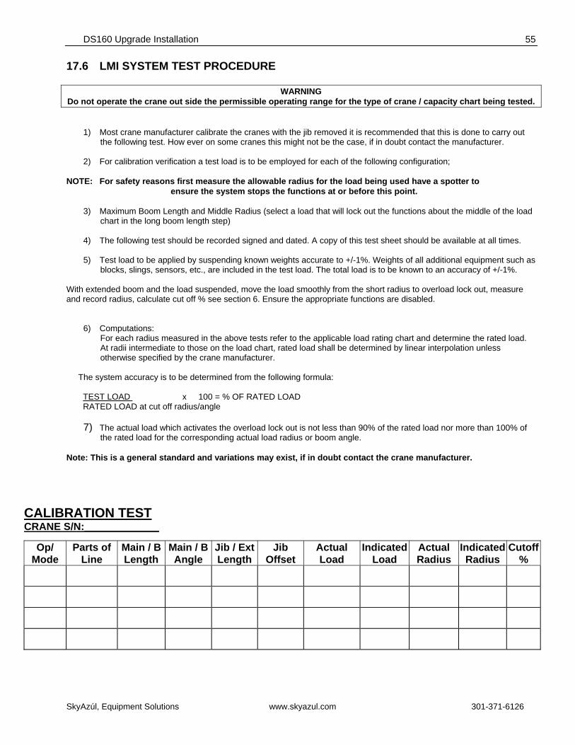
17.6 LMI SYSTEM TEST PROCEDURE
WARNING Do not operate the crane out side the permissible operating range for the type of crane / capacity chart being tested.
1) Most crane manufacturer calibrate the cranes with the jib removed it is recommended that this is done to carry out
the following test. How ever on some cranes this might not be the case, if in doubt contact the manufacturer.
2) For calibration verification a test load is to be employed for each of the following configuration;
NOTE: For safety reasons first measure the allowable radius for the load being used have a spotter to ensure the system stops the functions at or before this point.
3) Maximum Boom Length and Middle Radius (select a load that will lock out the functions about the middle of the load chart in the long boom length step)
4) The following test should be recorded signed and dated. A copy of this test sheet should be available at all times.
5) Test load to be applied by suspending known weights accurate to +/-1%. Weights of all additional equipment such as
blocks, slings, sensors, etc., are included in the test load. The total load is to be known to an accuracy of +/-1%. With extended boom and the load suspended, move the load smoothly from the short radius to overload lock out, measure and record radius, calculate cut off % see section 6. Ensure the appropriate functions are disabled.
6) Computations: For each radius measured in the above tests refer to the applicable load rating chart and determine the rated load. At radii intermediate to those on the load chart, rated load shall be determined by linear interpolation unless otherwise specified by the crane manufacturer.
The system accuracy is to be determined from the following formula: TEST LOAD x 100 = % OF RATED LOAD RATED LOAD at cut off radius/angle
7) The actual load which activates the overload lock out is not less than 90% of the rated load nor more than 100% of the rated load for the corresponding actual load radius or boom angle.
Note: This is a general standard and variations may exist, if in doubt contact the crane manufacturer.
CALIBRATION TEST
CRANE S/N:_____________
Op/ Mode
Parts of Line
Main / B Length
Main / B Angle
Jib / ExtLength
Jib Offset
Actual Load
Indicated Load
Actual Radius
IndicatedRadius
Cutoff%


SkyAzúl, Equipment Solutions www.skyazul.com 301-371-6126

SkyAzúl, Equipment Solutions www.skyazul.com 301-371-6126
SkyAzúl, Inc. 16 Walnut Street Middletown, MD 21769 Phone 301-371-6126 Fax 301-371-0029 [email protected] www.skyazul.com