
ds 63100 9201 en ls500 -1 - Rasesa · Amplifier-separated type Conforming to EMC Directive...
16
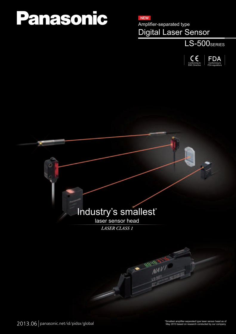
2013.06 panasonic.net/id/pidsx/global LS-500SERIES Digital Laser Sensor Amplifier-separated type Conforming to EMC Directive Conforming to FDA regulations Industry’s smallest * laser sensor head LASER CLASS 1 *Smallest amplifier-separated type laser sensor head as of May 2013 based on research conducted by our company
Transcript of ds 63100 9201 en ls500 -1 - Rasesa · Amplifier-separated type Conforming to EMC Directive...
2013.06 panasonic.net/id/pidsx/global
LS-500SERIES
Digital Laser SensorAmplifier-separated type
Conforming toEMC Directive
Conforming toFDA regulations
Industry’s smallest*
laser sensor head
LASER CLASS 1
*Smallest amplifier-separated type laser sensor head as of May 2013 based on research conducted by our company

Industry’s smallest*
head
*Smallest amplifier-separated type laser sensor head as of May 2013 based on research conducted by our company
Thru-beam
M6 head sensing type
LS-H101
One-pointMM66 iinnssttaallllaattiioonnMM
1 m 3.281 ftsensing range
(In STD amplifier
response time mode)
Wafer detection Workpiece orientation detection
30 mm 1.181 in
M6
Body: Stainless steel (SUS)
Operation indicator (receiver only)
2
Wafer
Actual size
1,000 39.370
Unit: mm in
5
ø3.5ø0.138
ø5ø0.197
500 19.685100 3.937
Beam-emitting part
ø2.3ø0.091
ø2ø0.079
Lead frame position detection
Featuring stainless steel
(SUS) enclosure that won’t
break when bumped during
installation or maintenance.
The LS-H101 features an
easy-to-install design.
1 m 3.sensing
Two-pointinstallation
Simpleppoossiittiioonniinngg
s
*Smallest amplifier-separated type laser sensor head as of May 2013 based on research conducted by our company
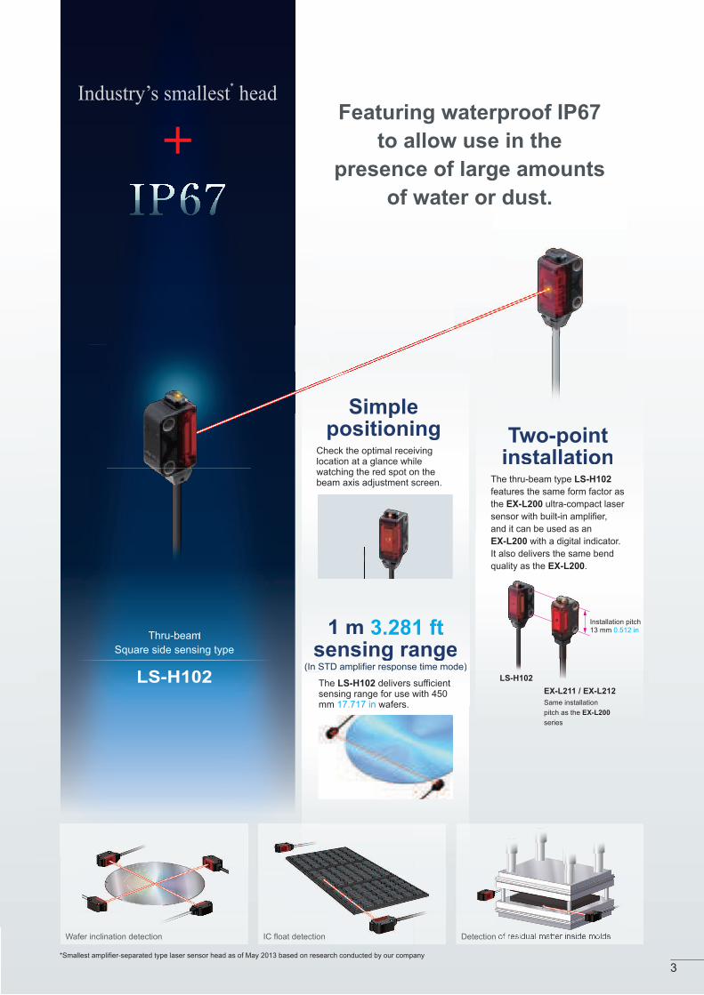
Thru-beam
Square side sensing type
LS-H102
Industry’s smallest*
head
.281 ftg range
Installation pitch13 mm 0.512 in
EX-L211 / EX-L212
LS-H102
STD amplifier res(In ST response time mode)
Wafer inclination detection IC float detection Detection of residual matter inside molds
Same installation
pitch as the EX-L200
series
3
Featuring waterproof IP67
to allow use in the
presence of large amounts
of water or dust.
The thru-beam type LS-H102
features the same form factor as
the EX-L200 ultra-compact laser
sensor with built-in amplifier,
and it can be used as an
EX-L200 with a digital indicator.
It also delivers the same bend
quality as the EX-L200.
Check the optimal receiving location at a glance while watching the red spot on the beam axis adjustment screen.
The LS-H102 delivers sufficient sensing range for use with 450 mm 17.717 in wafers.
Thru-beam

Coaxial reflective type
LS-H201
Small,longgg-ranggge spppot
Detection of workpieces through a work bench. Detection of threaded holes and threadDetection of gaskets in caps
Easy-to-seeoperatttiiionindicator
The LS-H201’s
operation indicator
is visible from all
directions.
ator
l
The LS-H201 produces a spot
with a diameter of 2 mm 0.079
in at a sensing range of up to
300 mm 11.811 in (in STD
amplifier response time mode).Coaxial designC
ø2 mmø0.079 in
300 mm11.811 in
Sensingtarget
Reflected light
Coaxial reflective type
LS-H201
4
By using a laser with high
linearity in a coaxial design, the
LS-H201 is able to deliver stable
sensing in confined spaces as
well as simple installation.
Laser lightReflective surface
Emittingelement
Reflective photoelectric sensor
Coaxial design
Receiving lens
Receiving element
Emittingpart
Receivingpart
Receivingpart
Coaxial principle
Industry’s smallest*
head
*Smallest amplifier-separated type laser sensor head as of May 2013 based on research conducted by our company
8 mm0.315 in
23 mm0.906 in
18 mm0.709 in
Gasket
Featuring a 60% smaller design (by volume)
than previous coaxial reflective models,
our smallest unit is smaller in every
dimension at just W 8 × H 23 × D 18 mm
W 0.315 × H 0.906 × D 0.709 in (excluding indicators).

Industry’sssmmaalllleesstt* aannddhinnest designth
Sensing rangeof 10 mm to 1 m
0.394 in to 3.281 ft(In STD amplifier response time mode)
Coaxial retroreflective type
LS-H901
Detection of tape Detection of bottles
The LS-H901 is even thinner
than previous models,
measuring just W 8 × H 23
(excluding indicators) × D 18 mm
W 0.315 × H 0.906 × D 0.709 in.
The LS-H901 supports
close-range sensing.
Detection of the top of DVDs, sheets of material, etc.
10 mm 0.394 in
1 m 3.281 ft
5
Industry’s smallest*
head
*Smallest amplifier-separated type laser sensor head as of May 2013 based on research conducted by our company
8 mm0.315 in
4 mm 0.157 in
Featuring a simple system design process
thanks to a light source that is placed in the
center of the sensor head and a coaxial design.

FX-500 fiber sensor
LS-500 laser sensor
Amplifier
LS-500
Maximum compatibility with fiber sensorsThe LS-500 features the same operation, menu
displays, and form factor as the FX-500 for increased
compatibility with fiber sensors.
Stable sensing over the long termThe LS-500’s threshold-tracking function helps
maintain stable sensing over the long term and reduce
maintenance man-hours. The incident light intensity
can be checked and the threshold automatically reset
at a user-selected interval to track changes in light
intensity due to environmental changes (such as dust,
etc.) over extended periods of time. Detection of beam axis misalignmentDual outputs (self-diagnosis output)The LS-500 can detect any reduction in incident light
intensity, for example due to the accumulation of dirt
such as dust, and issue an alarm. Output 2 can be set
as self-diagnosis output. When you teach the
threshold for output 1, output 2 is set accordingly,
allowing you to shift the threshold by a previously set
margin.
Logic operationsThe LS-500’s ability to perform three logic operations
(AND, OR, and XOR) on a standalone basis
eliminates the need for a dedicated controller, cuts
down on wiring, and lowers costs. This functionality
can also be combined with the FX-500.
Data bankEight sets of amplifier settings can be stored in the
unit’s built-in memory. The ability to save and load
settings reduces workload when changing the setup in
a multi-model production environment.
6
*Smallest amplifier-separated type laser sensor head as of May 2013 based on research conducted by our company
response times*
Engineered for maximum compatibility with fiber
sensors in every aspect of its design, from form factor
to operability, the LS-500 delivers an environment that
makes it easy to choose a laser sensor.

750 mm 29.528 in600 mm 23.622 in
450 mm 17.717 in300 mm 11.811 in
200 mm 7.874 in150 mm 5.906 in
1 m 3.281 ft1 m 3.281 ft1 m 3.281 ft1 m 3.281 ft1 m 3.281 ft1 m 3.281 ft
1 m 3.281 ft1 m 3.281 ft1 m 3.281 ft1 m 3.281 ft1 m 3.281 ft1 m 3.281 ft
0.01 to 1.5m 0.033 to 4.921 ft0.01 to 1m 0.033 to 3.281 ft
0.01 to 2 m 0.033 to 6.562 ft
0.01 to 1m 0.033 to 3.281 ft
0.01 to 2.5 m 0.033 to 8.202 ft
0.01 to 1m 0.033 to 3.281 ft
AppearanceType
Thru
-beam
type
Model No.
LS-H101
LS-H102
LS-H201
LS-H901
Sensor heads
Cylindrical
Square
Coaxial reflective type
Coaxial retroreflective type
Package without reflector
The LS-H901 is also available without a reflector (RF-330).
When ordering this type, add “-Y” at the end of the model number.
5 m 16.404 ft cable length type
5 m 16.404 ft cable length types (Standard: 2 m 6.562 ft) are available. When ordering this type, add “-C5” at the end of the model number.
LS-H901-Y
LS-H101-C5 LS-H102-C5 LS-H201-C5 LS-H901-C5
AppearanceType
Cable typeWith externalinput
Connector type
Connection method
Use quick-connection cable (4-core) (optional)
2 m 6.562 ft cabtyre cable (6-core) includedCable outer diameter: ø4 mm ø0.157 in
NPN open-collector transistor two outputs
PNP open-collectortransistor two outputs
NPN open-collectortransistor two outputs
PNP open-collectortransistor two outputse
OutputModel No.
LS-501
LS-501P
LS-501-C2
LS-501P-C2
Amplifiers
Quick-connection cables
AppearanceType
Connector foramplifier
Connector included with sensor headUse for maintenance, for example when another connector is damaged.
Model No.
CN-EP4
Connectors
Type Model No. Description
Description
CN-74-C1 Length: 1 m 3.281 ft
0.15 mm2 4-core cabtyre cable, with connector on one endCable outer diameter: ø3 mm ø0.118 in
0.15 mm2 2-core cabtyre cable, with connector on one endCable outer diameter: ø3 mm ø0.118 inUp to 15 sub cables can be connected to 1 main cable.
Length: 2 m 6.562 ft
Length: 1 m 3.281 ft
Length: 2 m 6.562 ft
CN-74-C2
Length: 5 m 16.404 ftCN-74-C5
CN-72-C1
CN-72-C2
Length: 5 m 16.404 ftCN-72-C5
Main cable(4-core)
Sub cable(2-core)
Quick-connection cable is not supplied with the connector type amplifier. Please order it separately.
Appearance
Sensing range
: HYPR : U-LG : LONG : STD : FAST : H-SP
7
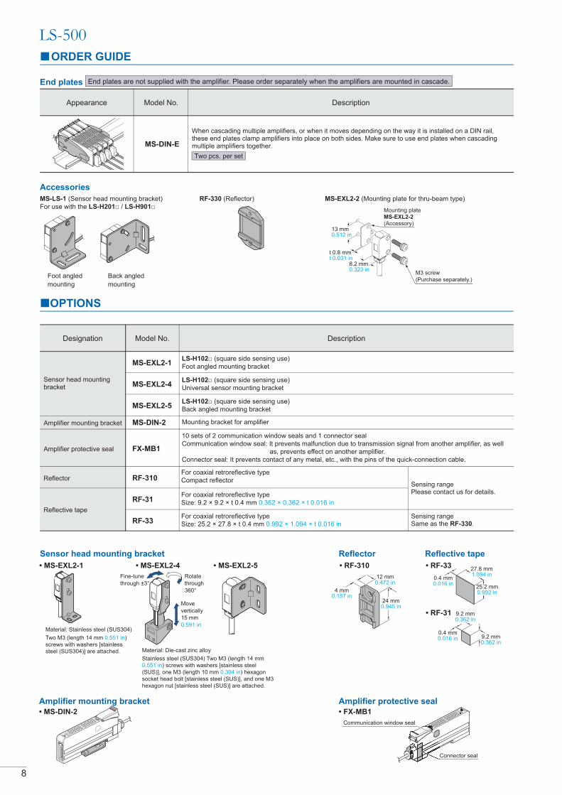
ORDER GUIDE
LS-500
8
OPTIONS
Sensor head mounting bracket
Designation Description
Sensor head mounting bracket
LS-H102
Foot angled mounting bracket
LS-H102
Universal sensor mounting bracket
LS-H102
Back angled mounting bracket
Mounting bracket for amplifier
Amplifier protective seal
10 sets of 2 communication window seals and 1 connector seal
Communication window seal: It prevents malfunction due to transmission signal from another amplifier, as well
as, prevents effect on another amplifier.
Model No.
0.551 in
screws with washers [stainless
Rotate
through
Move
vertically
15 mm
0.591 in
Amplifier mounting bracket Amplifier protective seal
Communication window seal
Connector seal
For coaxial retroreflective type
Compact reflector
For coaxial retroreflective type
For coaxial retroreflective type
Reflector
Reflective tape
Reflector
12 mm
0.157 in
Reflective tape
9.2 mm
9.2 mm
Amplifier mounting bracket
LS-500
End plates are not supplied with the amplifier. Please order separately when the amplifiers are mounted in cascade.
When cascading multiple amplifiers, or when it moves depending on the way it is installed on a DIN rail, these end plates clamp amplifiers into place on both sides. Make sure to use end plates when cascading multiple amplifiers together.
Appearance Model No. Description
Accessories
For use with the LS-H201 LS-H901
Foot angled
mounting
Back angled
mounting
0.512 in
t 0.8 mm
8.2 mm
Mounting plate
Two pcs. per set
Sensing range Same as the .
Sensing range Please contact us for details.
0.551 in
27.8 mm
25.2 mm0.992 in

Type
Model No.
Sensor heads
Coaxial
reflective type
Coaxial
retroreflective type
Item
Spot size
FAST
STD
LONG
HYPR
Approx. ø5 mm ø0.197 in or less
emitter of 1 m
Approx. ø2 mm ø0.079 in or less
11.811 in
or less
emitter of 1 m
Approx. ø5 mm ø0.197 in or less
emitter of 1 m
1 m
1 m
1 m
1 m
1 m
1 m
150 mm
200 mm
11.811 in
17.717 in
750 mm 29.528 in
0.01 to 1 m
0.01 to 1 m
0.01 to 1 m
0.01 to 1.5 m
0.01 to 2 m
0.01 to 2.5 m
1 m
1 m
1 m
1 m
1 m
1 m
Accessories
Net weight: 50 g approx.
Gross weight: 70 g approx.
Toothed lock washer: 2 pcs.
Cover: Polycarbonate
Enclosure: PBT
Cover: AcrylicMaterial Enclosure: PBT, Indicator cover: Polycarbonate,
Applicable amplifiers P P -C2
Sensing object
Operation indicator
1,000 V AC for one min. between all supply terminals connected together and enclosure
0.059 in amplitude in X, Y and Z directions for two hours each
2
Red semiconductor laser diode
Cable
Weight
0.1 mm2, single core two parallel shielded cables, 2 m long0.09 mm2 long
Sensin
g r
ange
LS-H101
Cylindrical
LS-H102
Small
LS-H201 LS-H901
Net weight: 50 g approx.
Gross weight: 80 g approx.
Net weight: 50 g approx.
Gross weight: 85 g approx.
2 mW
Net weight: 50 g approx.
Gross weight: 75 g approx.
2 mW 2 mW 1 mW
Protection
Ambient temperature
Ambient humidity
Ambient illuminance
Voltage withstandability
Insulation resistance
Vibration resistance
Shock resistance
Type
Peak emission wavelength
Laser class
Max. output
Environm
enta
l re
sis
tance
Em
itting e
lem
ent
.
reflector. In addition, the sensing range is the possible setting range
for the reflector. The sensor can detect an object less than 0.01 m away. Note that due to the principles on which coaxial retroreflective sensors
operate, if a mirrored object or other object that diffuses light readily is located close to the sensor, polarized light from these objects may be received,
causing unstable sensing. In such cases, use the amplifier unit’s receiving sensitivity function to lower the sensitivity, change the response time, or
move the sensor head away from the target object. The incident light intensity may vary with the condition of the reflector surface. When using one of
the applicable
LS-H101 LS-H102 series amplifier to level
2 or less. This is because there is a possibility of sensing becoming unstable.
9
LS-500

LS-500
10
Timer functions
SPECIFICATIONS
Amplifiers
Connector type
LS-501
LS-501P
Cable type
LS-501-C2
LS-501P-C2
Type
NPN Output
PNP OutputItem
Power consumption Normal operation: 1,200 mW or less (Current consumption 50 mA or less at 24 V supply voltage)
Supply voltage
Outputs(Output 1, Output 2)
Selectable either Light-ON or Dark-ON
Incorporated
Normal mode, differential mode, hysteresis mode, window comparator mode, selectable
Output operation
Short-circuit protection
Output 1
Output 2
Timer period
<NPN output type>
NPN open-collector transistor
Applied voltage: 30 V DC or less (between output and 0 V)
<PNP output type>
PNP open-collector transistor
Applied voltage: 30 V DC or less (between output and +V)
Response time: 2 ms or less
Response time
Laser emission halt / teaching (full-auto teaching, limit teaching, 2 point teaching) / logic operation setting / copy lock /
display adjustment / data bank load / data bank save, selectable
Sensing output setting
Monitor current output
2-level teaching / limit teaching / full auto teaching / manual adjustment
Operation indicator
Laser emission indicator
Output select indicator
Digital display
Incident light indication range
Sensitivity setting
Logical operation
Incorporated (Note 3)
-10 to +55°C (If 4 to 7 units are mounted close together, -10 to +50°C ; if 8 to 16 units (cable type: 8 to 12 units)
are mounted close together, -10 to +45 °C ) (No dew condensation or icing allowed), Storage: -20 to +70 °C
Interference prevention function
Ambient temperature
<NPN output type>
NPN non-contact input
High: +8 V to +V DC or open,
Low: 0 to +2 V DC (source current 0.5 mA or less)
<Output 1>
switchable either effective of ineffective
Normal mode, differential mode, hysteresis mode,
self-diagnostic output mode, selectable
Normal mode, differential mode, hysteresis mode, self-diagnostic
output mode, answer-back output mode, selectable
<Output 2>
switchable either effective of ineffective
Material
Protection
Cable
Weight
Accessory
Ambient humidity
Voltage withstandability
Insulation resistance
Vibration resistance
Shock resistance
35 to 85 % RH, Storage: 35 to 85 % RH
1,000 V AC for one min. between all supply terminals connected together and enclosure
10 to 150 Hz frequency, 0.75 mm 0.030 in
2
328.084 ft is possible with 0.3 mm2, or more, cable.
FX-MB1 (Amplifier protective seal): 1 set
0.2 mm2 6-core cabtyre cable, 2 m 6.562 ft long
<PNP output type>
PNP non-contact input
High: +4 V to +V DC (sink current 3.0 mA or less),
Low: 0 to +0.6 V DC or open
resis
tance
Mod
el N
o.
Notes: 1) Where measurement conditions have not been specified precisely, the conditions used were an ambient temperature of +23 °C .
12 to 24 V DC % Ripple P-P 10 % or less+10–15
11
LS-500
3
4
5
6
1
2
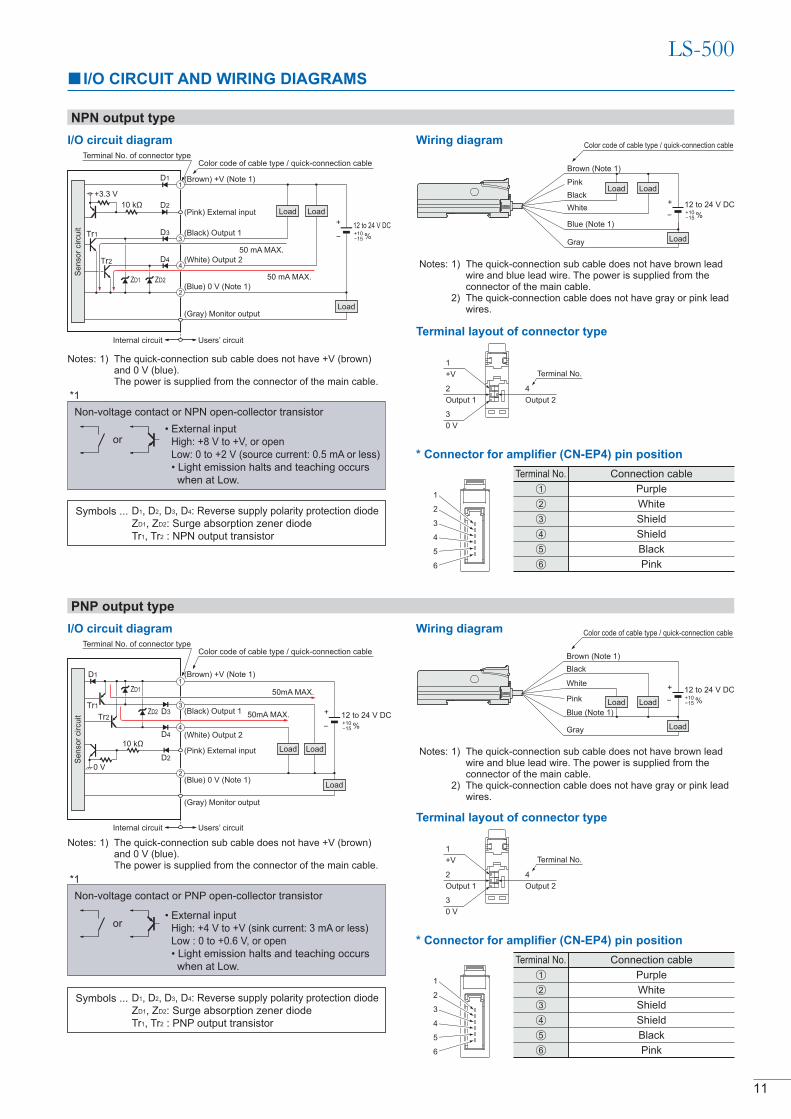
Symbols ... D1, D2, D3, D4: Reverse supply polarity protection diode
ZD1, ZD2: Surge absorption zener diode
Tr1, Tr2 : NPN output transistor
Non-voltage contact or NPN open-collector transistor
or High: +8 V to +V, or open
Low: 0 to +2 V (source current: 0.5 mA or less)
when at Low.
*1
D1
NPN output type
I/O CIRCUIT AND WIRING DIAGRAMS
I/O circuit diagram
PNP output type
Users’ circuitInternal circuit
Notes: 1) The quick-connection sub cable does not have brown lead wire and blue lead wire. The power is supplied from the connector of the main cable.
2) The quick-connection cable does not have gray or pink lead wires.
Wiring diagram
Terminal layout of connector type
12 to 24 V DC+
Color code of cable type / quick-connection cable
Color code of cable type / quick-connection cableWiring diagram
Brown (Note 1)
White
Pink
Blue (Note 1)
Gray
(Brown) +V (Note 1)
Tr1
Tr2
50mA MAX.
(Black) Output 1
(Gray) Monitor output
(White) Output 2
0 V
12 to 24 V DC+
1
+V Terminal No.
3
0 V
2
Output 1
4
Output 2
Notes: 1) The quick-connection sub cable does not have brown lead wire and blue lead wire. The power is supplied from the connector of the main cable.
2) The quick-connection cable does not have gray or pink lead wires.
Color code of cable type / quick-connection cable
12 to 24 V DC+
4
1
50mA MAX.
Load
Load
Load
Terminal No. of connector type
Symbols ... D1, D2, D3, D4: Reverse supply polarity protection diode
ZD1, ZD2: Surge absorption zener diode
Tr1, Tr2 : PNP output transistor
*1
Non-voltage contact or PNP open-collector transistor
or
I/O circuit diagram
3
Load
Black
LoadLoad
* Connector for amplifier (CN-EP4) pin position
Notes: 1) The quick-connection sub cable does not have +V (brown) and 0 V (blue).The power is supplied from the connector of the main cable.
High: +4 V to +V (sink current: 3 mA or less)
Low : 0 to +0.6 V, or open
when at Low.
1
2
3
4
5
6
Terminal No. Connection cable
Purple
White
Shield
Shield
Black
Pink
Terminal No. Connection cable
Purple
White
Shield
Shield
Black
Pink
Terminal layout of connector type
1
+V Terminal No.
3
0 V
2
Output 1
4
Output 2
* Connector for amplifier (CN-EP4) pin position
%+10
%+10
%+10
Users’ circuitInternal circuit
Sensor
circuit
Color code of cable type / quick-connection cable
(Brown) +V (Note 1)
(White) Output 2
(Blue) 0 V (Note 1)
(Gray) Monitor output
(Black) Output 1Tr1
Tr2
LoadLoad
+3.3 V
1
4
2
Terminal No. of connector type
12 to 24 V DC+
ZD2ZD1
D1
D2
D3
D4
Notes: 1) The quick-connection sub cable does not have +V (brown) and 0 V (blue).The power is supplied from the connector of the main cable.
50 mA MAX.
3 %+10
Load
50 mA MAX.
Brown (Note 1)
Black
White
Pink
Blue (Note 1)
Gray
Load
Load
3
4
5
6
1
2
D4
D3
D2Sensor
circuit
2
ZD1
ZD2
(Blue) 0 V (Note 1)
Load
1
2
3
4
5
6

12
PRECAUTIONS FOR PROPER USE
LS-500
Cautions for laser beams
Part description (Amplifier)
Mounting
<How to mount the amplifier>
<Not requiring the metal plate> <Requiring the metal plate>
Amplifier
<How to mount the sensor head>
<How to remove the amplifier>
Sensor head
LS-H101
LS-H201 LS-H901
MS-EXL2-2
MS-EXL2-1MS-EXL2-2
LS-H102
Fig. 1 Proper positioning
Fig. 2 Improper positioning
Wiring
LS-501 P2
2
1
2 1
2 1
MS-EXL2-2
MS-EXL2-1
MS-EXL2-1
MS-EXL2-1
MS-EXL2-2
MS-LS-1MS-LS-1
MS-LS-1

PRECAUTIONS FOR PROPER USE
Others
DIMENSIONS (Unit: mm in)
LS-H101 LS-H102
LS-H201 LS-H901 LS-501 LS-501P
LS-501-C LS-501P-C
1212
12
2
LS-500
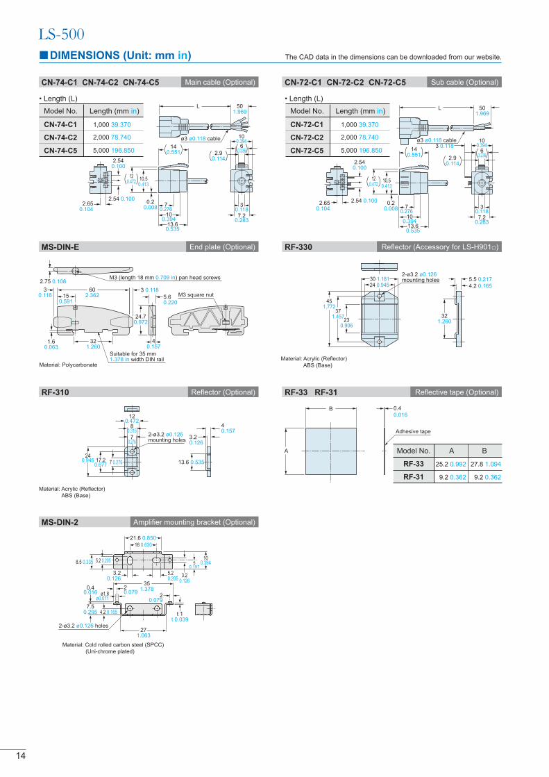
Material: Acrylic (Reflector)
ABS (Base)
2-ø3.2 ø0.126mounting holes
7 0.27617.20.677
240.945
120.472
70.276
3.20.126
40.157
13.6 0.535
80.315
451.772
371.457
230.906
2-ø3.2 ø0.126mounting holes
Material: Acrylic (Reflector)
ABS (Base)
4.2 0.165
5.5 0.217
321.260
351.378
271.063
20.079
t 1t 0.039
0.40.016
7.50.295 4.2 0.165
20.079ø1.8
ø0.071
2-ø3.2 ø0.126 holes
3.20.126
5.20.205
8.5 0.335
3.20.126
50.197
100.394
Material: Cold rolled carbon steel (SPCC)
(Uni-chrome plated)
Adhesive tape
A
B 0.4
0.016
Model No.
RF-33
RF-31
A
25.2 0.992
9.2 0.362
B
27.8 1.094
9.2 0.362
LS-500
14
The CAD data in the dimensions can be downloaded from our website.DIMENSIONS (Unit: mm in)
CN-72-C1
CN-72-C5
Model No. in)
1,000 39.370
5,000 196.850
CN-72-C2 2,000 78.740
CN-74-C1
CN-74-C2
Model No. in)
1,000 39.370
2,000 78.740
CN-74-C5 5,000 196.850
7.20.283
30.118
0.20.008
13.60.535
100.394
70.276
2.650.104
ø3 ø0.118 cable ø3 ø0.118 cable
2.650.104
2.54 0.100
2.540.100
7.20.283
30.118
0.20.008
13.60.535
100.394
70.276
501.969
3 0.118
501.969
2.540.100
2.54 0.100
1.60.063
321.260
40.157
5.60.220
2.75 0.108M3 (length 18 mm 0.709 in) pan head screws
M3 square nut150.591
3 0.11830.118
602.362
Material: Polycarbonate
Suitable for 35 mm1.378 in width DIN rail
120.472
120.472
10.50.413
140.551 2.9
0.114
60.236 6
0.2362.9
0.114
140.551
10.50.413
100.394 10
0.394
24.70.972
30 1.18124 0.945
21.6 0.850
16 0.630
5.2 0.205
CN-74-C1 CN-74-C2 CN-74-C5 Main cable (Optional) Sub cable (Optional)CN-72-C1 CN-72-C2 CN-72-C5
MS-DIN-E End plate (Optional) RF-330
RF-310 Reflector (Optional)
MS-DIN-2 Amplifier mounting bracket (Optional)
Reflective tape (Optional)RF-33 RF-31

10°
3.4°
R23.6R0.929
110.433
2.40.094
15
The CAD data in the dimensions can be downloaded from our website.DIMENSIONS (Unit: mm in)
LS-500
Rear mounting bracket
Foot angled mounting bracket
Universal sensor mounting bracket
Assembly dimensions
Assembly dimensions
Material: Stainless steel (SUS304)Two M3 (length 14 mm 0.551 in) screws with washers [stainless steel (SUS304)] are attached.
Material: Stainless steel (SUS304) * Without using the mounting plate, beam misalignment may occur.
Mounting drawing with the emitter
Assembly dimensions
Note: Screws are not attached. Purchase separately.
t 0.8t 0.031
1.50.059
2.6 0.102
10.039 2-ø3.05 ø0.120
10.60.417
2.8 0.110
3.05 0.120
2.8 0.110
18.80.740
3.5 0.138 1 0.039
2.6 0.102
Beam-emitting part
90.354
4.90.193
2
60.236
140.551
1.50.059
120.472
9.50.374
ø8.5ø0.335
40.157
5.5 0.217
15.50.610
19.50.768
2-hexagon nut seats
ø3.3 ø0.130 thru-hole
2-ø3.2 ø0.126mounting holes
3.8 0.150
140.551
5.5 0.217
150.591
3
3-M3 × 0.5 0.020
10°t 1.5t 0.059
2.50.098
2.50.098
160.630
13 0.512
2.50.098
1
11.20.441
3.450.136
8.4 0.331
3.050.120
3°
30.118
130.512
1.5 0.059
4.10.161
1.50.059
ø8.5ø0.335
3.05 0.120
4 0.157
25.51.00431.5
1.240
301.181
25.51.00428.5
1.122
140.551
60.236
9.50.374
130.512
3 0.118
5.1 0.201
ø8.5 ø0.335
3.8 0.150
Beam-receiving part
2-ø3.2 ø0.126mounting holes
31.51.240
301.181
(Note 1)
Note : This is the adjustable range of the movable part.
19.50.768
2.30.091
6.5 0.256
Mounting drawing with the receiver of
80.315
3 0.118
30.118
4.50.177
16.50.650
8.80.346
3.4 0.134
14° R13R0.512
30.118
14.20.559
t 1.2t 0.047
18.50.728
3.20.126
3.050.120
3.050.120
t 1.5t 0.059
3-M3×0.5
13 0.512
2.50.098
2.50.0982.5 0.098
6 0.236
3.5 0.138
110.433
3.50.138
40.157
8.70.343
50.197
2.40.094
2-ø2.2 ø0.087
t 1.2t 0.047
3.50.138
140.551
t 1.2t 0.047
40.157
R1.5R0.0592-M2 × 0.4 0.016
14.50.571
2.50.098
R23.6R0.929
3.4°
3°
20.2°
26 1.024
29.51.161
190.748
190.748
23.60.929
130.512 16.4
0.646 130.51224
0.945
160.630
21
21
21
6.70.264
150.591
120.472
150.591
Mounting drawing with the
3.050.120
3.20.126
2 0.0798 0.315
3.50.138
3.2 0.126
12.5 0.4927.50.295
30.118
t 1.2t 0.047
14°R13 R0.512
431.693
3.05 0.120
3.10.122
13 0.512
26.5 1.043
t 1.5 t 0.059
3-M3×0.5
2.50.098
10°
2.50.098
2.50.098
16 0.63013 0.512
Beam-receiving part
80.315
2 0.0793.20.1263.5
0.138
30.118
120.472
1.2 0.047
13 0.512
t 1.2t 0.047
R13 R0.512
12.5 0.492
3.20.126
7.50.295
11.6 0.457
14°
MS-LS-1 MS-EXL2-1
MS-EXL2-2
MS-EXL2-4
MS-EXL2-5
24.10.949
160.630
331.299
431.693
26.51.043
160.630
8.80.346
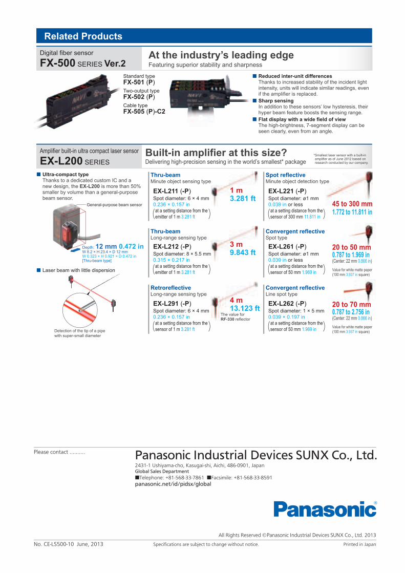
Ultra-compact typeThanks to a dedicated custom IC and a new design, the EX-L200 is more than 50% smaller by volume than a general-purpose beam sensor.
Laser beam with little dispersion
General-purpose beam sensor
Standard type
FX-501 (P)
Two-output type
FX-502 (P)
Cable type
FX-505 (P)-C2
Related Products
Digital fiber sensor
FX-500 SERIES Ver.2At the industry’s leading edgeFeaturing superior stability and sharpness
Amplifier built-in ultra compact laser sensor
EX-L200 SERIES
Built-in amplifier at this size?Delivering high-precision sensing in the world’s smallest* package
Reduced inter-unit differencesThanks to increased stability of the incident light intensity, units will indicate similar readings, even if the amplifier is replaced.
Sharp sensingIn addition to these sensors’ low hysteresis, their hyper beam feature boosts the sensing range.
Flat display with a wide field of viewThe high-brightness, 7-segment display can be seen clearly, even from an angle.
EX-L291 (-P)Spot diameter: 6 × 4 mm
0.236 × 0.157 in
at a setting distance from the
sensor of 1 m 3.281 ft
EX-L211 (-P)Spot diameter: 6 × 4 mm
0.236 × 0.157 in
at a setting distance from the
emitter of 1 m 3.281 ft
EX-L212 (-P)Spot diameter: 8 × 5.5 mm
0.315 × 0.217 in
at a setting distance from the
emitter of 1 m 3.281 ft
The value for RF-330 reflector
1 m 3.281 ft
3 m 9.843 ft
4 m 13.123 ft
45 to 300 mm1.772 to 11.811 in
20 to 50 mm0.787 to 1.969 in(Center: 22 mm 0.866 in)
20 to 70 mm0.787 to 2.756 in(Center: 22 mm 0.866 in)
Thru-beamMinute object sensing type
Thru-beamLong-range sensing type
RetroreflectiveLong-range sensing type
EX-L262 (-P)Spot diameter: 1 × 5 mm
0.039 × 0.197 in
at a setting distance from the
sensor of 50 mm 1.969 in
EX-L221 (-P)Spot diameter: ø1 mm
0.039 in or less
at a setting distance from the
sensor of 300 mm 11.811 in
EX-L261 (-P)Spot diameter: ø1 mm
0.039 in or less
at a setting distance from the
sensor of 50 mm 1.969 in
Spot reflectiveMinute object detection type
Convergent reflectiveSpot type
Convergent reflectiveLine spot type
*Smallest laser sensor with a built-in amplifier as of June 2012 based on research conducted by our company.
Depth: 12 mm 0.472 inW 8.2 × H 23.4 × D 12 mm W 0.323 × H 0.921 × D 0.472 in[Thru-beam type]
Value for white matte paper (100 mm 3.937 in square)
Value for white matte paper (100 mm 3.937 in square)Detection of the tip of a pipe
with super-small diameter
Please contact ..........
2431-1 Ushiyama-cho, Kasugai-shi, Aichi, 486-0901, JapanGlobal Sales Department
■Telephone: +81-568-33-7861 ■Facsimile: +81-568-33-8591
panasonic.net/id/pidsx/global
All Rights Reserved © 2013
Specifications are subject to change without notice. Printed in JapanNo. CE-LS500-10 June, 2013


