DS-08 GO BUS PARK & RIDE DESIGN STANDARD
121
DS-08 GO BUS PARK & RIDE DESIGN STANDARD Version 1.0 March 2021
Transcript of DS-08 GO BUS PARK & RIDE DESIGN STANDARD

DS-08GO BUS PARK & RIDE DESIGN STANDARD Version 1.0March 2021

DESIGN STANDARDS ii
GO BUS PARK & RIDE DESIGN STANDARD
Metrolinx Design Standards GO Bus Park & Ride Design Standard
Publication Date: March 19, 2021COPYRIGHT © 2021
Metrolinx,an Agency of the Government of Ontario
The contents of this publication may be used solely as required for and during a project assignment from Metrolinx or for and during preparing a response to a Metrolinx procurement request. Otherwise, this publication or any part thereof shall not be reproduced, re-distributed, stored in an electronic database or transmitted in any form by any means, electronic, photocopying or otherwise, without written permission of the copyright holder. In no event shall this publication or any part thereof be sold or used for commercial purposes.
The information contained herein or otherwise provided or made available ancillary hereto is provided “as is” without warranty or guarantee of any kind as to accuracy, completeness, fitness for use, purpose, non-infringement of third party rights or any other warranty, express or implied. Metrolinx is not responsible and has no liability for any damages, losses, expenses or claims arising or purporting to arise from use of or reliance on the information contained herein.

DESIGN STANDARDS iii
GO BUS PARK & RIDE DESIGN STANDARD
TABLE OF CONTENTS
1 INTRODUCTION .............................................................. 1
1.1 Preface / Overview ........................................................... 1
1.2 Design Principles for a Regional Network. .................... 2
1.3 The Customer Journey ..................................................... 11
1.4 Touch Points & Infrastructure Design Principles ........... 13
1.5 Transportation Requirements ......................................... 13
2 ADMINISTERING STANDARDS .................................... 15
2.1 How to Use This Document ............................................. 15
2.2 Legislative Codes & Standards........................................ 16
2.3 Design Review, Submittal Process & Requirements ..... 17
2.4 Acronyms & Terminology ................................................. 18
3 GO BUS PARK & RIDE SITE CLASSIFICATION ........... 23
3.1 Site Types ........................................................................... 23
4 PRINCIPAL ELEMENTS ................................................... 25
4.1 Overview ............................................................................ 25
4.2 Safety & Security ............................................................... 27
4.2.1 Life Safety ............................................................. 27
4.2.2 CPTED ................................................................... 27
4.2.3 Bus Safety ............................................................. 30
4.2.4 CCTV ..................................................................... 31
4.2.5 Audio/Public Announcement System ............... 32
4.2.6 Emergency Assistance Device- Reserved ........ 32
4.3 Signage .............................................................................. 33
5 SITE & LANDSCAPE DESIGN ........................................ 48
5.1 Streetscape ....................................................................... 48
5.2 Active Transportation Circulation ................................... 51
5.3 Site Furnishing .................................................................. 57
5.4 Barriers ............................................................................... 59
5.5 Site Lighting ...................................................................... 64
5.6 Pedestrian Scale Lighting ................................................ 66
5.7 Planting Design Requirements ........................................ 67

DESIGN STANDARDS iv
GO BUS PARK & RIDE DESIGN STANDARD
8 APPENDICES........................................................................ 88
8.1 Appendix A- Matrix of Kit of Parts..................................... 89
8.2 Appendix B- Washrooms & Ancillary Facilities............... 91
8.3 Appendix C- Schedules...................................................... 100
6 PASSENGER AMENITIES & ANCILLARY ELEMENTS 74
6.1 Overview ............................................................................ 74
6.2 Passenger Shelter ............................................................. 74
6.3 Fare Device ........................................................................ 75
6.4 Internet ............................................................................... 76
6.5 Bike Shelter ........................................................................ 77
6.6 Advertising (Non-Fare Revenue) ..................................... 81
6.7 Food Vendor...................................................................... 82
6.8 Retail Vending ................................................................... 83
7 COMMUNICATIONS........................................................... 84
7.1 Distribution Network............................................................ 84
7.2 Inter-Facility Network........................................................... 84
7.3 Communications Cabinet.................................................... 84

DESIGN STANDARDS v
GO BUS PARK & RIDE DESIGN STANDARD
LIST OF FIGURES
1 INTRODUCTION
Figure 1-1: GO Bus Park & Ride ................................................... 1
Figure 1-2: Customer Journey Diagram ..................................... 12
2 ADMINISTERING STANDARDS
Figure 2-1: How to Use This Document ...................................... 15
4 PRINCIPAL ELEMENTS
Figure 4-1: DS-02 Universal Design Standard ........................... 26
Figure 4-2: DS-05 Sustainable Design Standard ...................... 26
Figure 4-3: CPTED, Natural Surveillance ................................... 28
Figure 4-4: CPTED, Natural Access Control .............................. 28
Figure 4-5: CPTED, Territorial Reinforcement ........................... 28
Figure 4-6: CPTED, Maintenance ................................................ 29
Figure 4-7: Typical GO Bus Park & Ride Signage Applications - Type A (Major Bus Node) ............................................................. 39
Figure 4-8: Typical GO Bus Park & Ride Signage Applications - Type B (Minor Bus Node) ............................................................. 40
Figure 4-9: Typical GO Bus Park & Ride Signage Applications - Type C (Bus Collector) .................................................................. 41
Figure 4-10: Typical Trailblazer Signage Sequencing .............. 46
5 SITE & LANDSCAPE DESIGN
Figure 5-1: Streetscape Within Metrolinx Boundary................. 49
Figure 5-2: Streetscape Beyond Metrolinx Boundary .............. 49
Figure 5-3: DWA Diagram- Type A (Major Bus Node) ............... 52
Figure 5-4: Entry Sidewalk Access Diagram- Type A (Major Bus Node) or Type B (Minor Bus Node)................................................. 53
Figure 5-5: Entry Sidewalk Access Diagram- Type C (Bus Collector) ........................................................................................ 54
Figure 5-6: MUP Diagram- Type A (Major Bus Node) or Type B (Minor Bus Node) ........................................................................... 55
Figure 5-7: MUP Diagram- Type C (Bus Collector) .................... 55
Figure 5-8: Bike Path Diagram .................................................... 56
Figure 5-9: Bike Path and Sidewalk Intersection ....................... 56
Figure 5-10: Exterior Seating ...................................................... 57
Figure 5-11: Tri-Waste Receptacle Diagram .............................. 58
Figure 5-12: Decorative Metal Fencing ...................................... 59
Figure 5-13: Bollard Diagram ...................................................... 60
Figure 5-14: Retaining Wall Diagram .......................................... 61
Figure 5-15: Sound Attentuation Diagram ................................ 63
Figure 5-16: Bus Loop Lighting Diagram ................................... 64
Figure 5-17: Parking Lot Lighting Diagram ................................ 65

DESIGN STANDARDS vi
GO BUS PARK & RIDE DESIGN STANDARD
Figure 5-18: PUDO Lighting Diagram ........................................ 65
Figure 5-19: Pedestrian Scale Lighting Diagram....................... 66
Figure 5-20: Street Tree Planting in Grates ................................ 69
Figure 5-21: Street Tree Planting in Open Pits .......................... 70
Figure 5-22: Tree Planting in Raised Planter .............................. 70
Figure 5-23: Bioswale................................................................... 70
Figure 5-24: Shrub Planting in Planter ....................................... 71
Figure 5-25: Shrub Planting in Bioswale .................................... 71
Figure 5-26: Shrub Planting Providing Visual Buffer ................ 72
Figure 5-27: Sidewalk Sod Restoration ...................................... 73
6 PASSENGER AMENITIES & ANCILLARY FACILITIES
Figure 6-1: Typical Shelter Type Illustrations ............................. 75
Figure 6-2: Type A (Major Bus Node) or Type B (Minor Bus Node) Open Bike Storage- 12 Bike Capacity, minimum ........................ 78
Figure 6-3: Type C (Bus Collector) Open Bike Storage- 4 bike capacity, minimum ......................................................................... 79
Figure 6-4: Bike Rack Layout ....................................................... 79
Figure 6-5: Covered Bike Storage Station ................................. 79
Figure 6-6: Secure Bike Storage- 16 Bike Capacity, as per DS-07 Bike Infrastructure Standard ......................................................... 80
Figure 6-7: Typical Food Truck Vehicle Size and Clearance for Waiting ............................................................................................ 82
7 COMMUNICATION
Figure 7-1: Typical Communications Component Placement at a Type A (Major Bus Node) facility......................................................87
8 APPENDICES
Figure 8-1: Typical Washroom & Ancillary Facilities Elevation Diagram ........................................................................................... 92
Figure 8-2: Typical Washroom & Ancillary Facilities Floor Plan Layout Diagram.................................................................................. 93
Figure 8-3: Typical Washroom & Ancillary Facilities Elevation Diagram............................................................................................... 108
Figure 8-4: Washroom & Ancillary Facilities Finish Floor Plan Diagram............................................................................................... 110
Figure 8-5: Washroom & Ancillary Facilities Ceiling Plan Diagram............................................................................................... 112

DESIGN STANDARDS vii
GO BUS PARK & RIDE DESIGN STANDARD
LIST OF TABLES
2 ADMINISTERING STANDARDS
Table 2-1: Terminology & Definitions .......................................... 18
Table 2-2: Table of Acronyms ...................................................... 18
4 PRINCIPAL ELEMENTS
Table 4-1: Information Highly Relevant to GO Bus Park & Ride Signage (As per DS-03 MTX Wayfinding Design Standard) ...... 37
Table 4-2: Bilingual Guidelines in Integrated GO/MTO Park & Ride (Carpool Lot Signage Guidelines, 14-15) ............................ 38
6 PASSENGER AMENITIES & ANCILLARY FACILITIES
Table 6-1: Shelter Type based on GO Bus Park & Ride Classification .................................................................................. 74
Table 6-2: Advertising Panel and Device Typologies, Design and Sizes...................................................................................................... 81
8 APPENDICES
Table 8-1: Kit of Parts Matrix ........................................................ 89
Table 8-2: Washrooms & Ancillary Facilities Envelope Details and Requirements ................................................................................. 94
Table 8-3: Public Washroom Requirements ............................... 96
Table 8-4: Janitor / Maintenance Room Requirements ............ 98
Table 8-5: Washroom & Ancillary Facilities General Finishes .. 100
Table 8-6: Washroom & Ancillary Facilities Floor Finishes and Design Requirements....................................................................... 103
Table 8-7: Washroom & Ancillary Facilities Wall Finishes and Design Requirements .................................................................... 104
Table 8-8: Washroom & Ancillary Facilities Door Finishes and Design Requirements........................................................................105
Table 8-9: Washroom & Ancillary Facilities Window Finishes and Design Requirements....................................................................... 107
Table 8-10: Washroom & Ancillary Facilities Specialty Items and Design Requirements....................................................................... 107
Table 8-11: Washroom & Ancillary Facilities Exterior Finishes Schedule ......................................................................................... 109
Table 8-12: Washroom & Ancillary Facilities Interior Finishes Schedule............................................................................................. 111
Table 8-13: Washroom & Ancillary Facilities Luminaire Types. 113

DESIGN STANDARDS 1
GO BUS PARK & RIDE DESIGN STANDARD
1 INTRODUCTION
1.1 PREFACE / OVERVIEW
GO Bus Park & Rides are intermodal transfer facilities, providing a location for travelers to transfer between the auto mode and transit or between the single occupant vehicle (SOV) and other high occupancy vehicle (HOV or carpool) modes. They may also host pedestrian, bicycle, automobile, bus transit, airport service, and other modes, depending on the location and community requirements. GO Bus Park & Rides do not include GO Rail Stations, bus terminals or other rapid transit stations that are served by GO bus. The lots are typically on MTO (Ministry of Transportation of Ontario) property and are owned by regional municipalities or MTO. They are operated and serviced by Metrolinx (GO Transit) and may be used by other local and regional carriers.
This document provides a design standard to inform public-facing elements of the GO Bus Park & Ride. The Design Standard provides requirements regarding future development and renovations to existing GO Bus Park & Rides. Metrolinx advocates for design excellence across all GO facilities, as mandated by the Metrolinx Board of Directors in 2013. Design Standard documents provide a coordinated approach to design excellence, improving the experience of GO facilities and reinforcing the Metrolinx brand.
The GO Bus Park & Ride Strategy and the DS-00 Front End document shall be referenced for further information.
Figure 1-1: GO Bus Park & Ride

DESIGN STANDARDS 2
GO BUS PARK & RIDE DESIGN STANDARD
1.2 DESIGN PRINCIPLES FOR A REGIONAL NETWORK
The Metrolinx vision for transit in the Greater Golden Horseshoe (GGH) region is to deliver a seamless, integrated end to end customer experience that is supported and reinforced by appropriate architectural, interior, landscape and urban design solutions across the network. Metrolinx is planning, designing and building projects that will shape the regional transit network of the future. Everyone in the region is a potential customer. A positive customer experience for all customers will:
• Support increased cross-boundary travel, and increased transfers;
• Enable more seamless and easy first and last-mile options;
• Support a shift in primary trip purpose from commuting to a broader range of trip purposes; and
• Ultimately build ridership and revenue across the network. The objective is a One Network experience that should feel like a seamless trip. From planning, booking, payment, access, use, and transfer to arrival at a final destination.
GO Expansion will be the backbone of an integrated transit network but Metrolinx is also responsible for extensive Subway, Light Rail, and Bus programs. We require a consistent consideration for the entire end-to-end customer journey to create a highly functional system with a connected customer experience.
Understanding and thoughtfully addressing the customer experience across the many touchpoints of the transit journey forms the foundation of this holistic design process. In addition, given the heavy capital investment in transit infrastructure intended to serve and drive economic development in the GGHA for the foreseeable future, it is imperative that we engage in a future thinking mindset, with design solutions that strive to be adaptable, enduring and responsive to the evolution of customer needs & the future of mobility.
The Principles
The six Design Principles below are overarching values that inform and guide the development of the Metrolinx Design Standards and integrate the physical, digital and human aspects of the end to end customer journey. They are as follows:
• Seamless
• Intuitive
• Inclusive
• Safe
• Reliable
• Thoughtful
These Principles largely apply to customer-facing elements and touchpoints such as payment experience, transfer

DESIGN STANDARDS 3
GO BUS PARK & RIDE DESIGN STANDARD
experience etc., while thoughtfully considering spatial adjacencies and sensory aspects of back-of-house elements such as noise, smells and sight lines that may impact the quality of a customer’s experience. The Design Principles are underpinned by safety and making all of our customer’s journeys as safe as possible.
These Guiding Principles set out to ensure that the architectural, interior, landscape and urban design includes, but is not limited to, the following:
SEAMLESS
1.2.1 The end-to-end Customer Experience shall be well-connected, convenient and friction-free to keep customers ‘on the move’.
Site and Public Realm
a) Station or facility site and applicable infrastructure shall be seamlessly connected to the public realm and right of ways and shall maximize opportunities to integrate into the surrounding community and urban or suburban fabric. Design solutions shall thoughtfully consider all modal access including dedicated bike lanes, future expansions, existing and future connections to other multi-modal transit services and adjacent local transit services, and highlight potential future opportunities for integration into the local context.
b) Minimize travel distances for all customers at all journey touchpoints, particularly at points of transfer
between one transit service/mode to the next.
i. The routes the customers take must be clear, direct, and short as possible.
ii. Design shall promote and facilitate ease of transfer between one mode and the next.
Architecture and Interiors
c) Seamless integration of infrastructure elements such as structural, mechanical, electrical and plumbing systems
i. An integrated approach to all systems, including drainage, lighting, and speakers, shall ensure that these elements are visually less prominent for aesthetic consistency, acoustical performance and overall quality while being easily accessible for maintenance.
ii. Optimum simplicity in the appearance of the infrastructure to conceal systems and to prevent vandalism.
iii. Lighting shall be well organized and where possible, integrated into the structure and built environment.

DESIGN STANDARDS 4
GO BUS PARK & RIDE DESIGN STANDARD
INTUITIVE
1.2.2 The end to end navigation experience must be simple, predictable and consistent throughout the region.
Site and Public Realm
a) A consistent landscape vision that includes a primary strategy that complements the Site and Architecture design.
b) Applying consistent design treatments along major pedestrian routes and bike lanes provides a recognizable experiential cue to customers and guides them towards the station or facility and platform. These pathways create seamless connections through the station environment or facility and supports station or facility identification for customers.
Architecture and Interiors
c) A strong and coherent design vision
i. Similar architectural expression, look and feel of infrastructure (consistent materials, architectural elements, design expression and detailing)
ii. Systematic and codified use of colour, modularity, materials, finishes and pattern that integrates with the existing transit infrastructure or system as applicable.
iii. A clear architectural strategy for the application of Elements of Consistency and Variability
d) Visual cues, features and/or elements to support intuitive wayfinding and highlight key decision-making points, such as access points, vertical circulation etc. through the use of lighting, colour, or materiality.
e) Simplified volumes and forms constructed along consistent horizontal and vertical datum’s. Consistent approach to form making, building volumes and detailing, shall reinforce an architectural signature that is recognizable across the system
f) The composition of elements and their visual hierarchy should reinforce a sense of order and help customers find their way
i. Signage and Wayfinding placement strategy and customer information shall always take precedence over Advertising.
ii. Space plan shall support wayfinding simplicity and accessibility, and aid in clarity of the locations of fare purchase and payment devices.
g) Limit visual clutter, distractions and conflicts with other visual elements. Services shall be concealed but accessible by operations and maintenance staff. Create a sense of order, comfort and security to ensure a straightforward and enjoyable customer experience. Designs shall present balanced, clutter-free spaces that are legible and easily understood by all users.

DESIGN STANDARDS 5
GO BUS PARK & RIDE DESIGN STANDARD
h) Modular approach to design and material application to generate an organizational structure for the clean integration of all building systems; develop a modular approach to systems, with structural, mechanical and electrical elements less visually prominent, and a systematic approach to how architectural, structural, mechanical and electrical designs are expressed.
Customer Needs and Amenities
i) Facilitate passenger flows
i. All passenger amenities, services and security items shall be thoughtfully consolidated to achieve maximum visibility, circulation space and clear, direct pedestrian flow.
ii. A clear strategy for organizing the hierarchy and consistency of customer amenities, including but not limited to fare equipment and devices, seating, and waste receptacles.
j) End to end information/notification experience
i. Infrastructure that supports the end-to-end information and travel notifications experience for customers must be holistically considered, including static, digital, reliable Wi-Fi connectivity and on-board strategies. There must be alignment between physical and digital messaging and alerts, both on-site and on the move.
k) Minimize escalator transfers where applicable.
INCLUSIVE
1.2.3 The end to end Customer Experience must serve the diverse needs and abilities of all travellers regardless of age, gender, income or familiarity of the system.
Site and Public Realm
a) Provide access for all through the implementation of the principles of Universal Design
i. Provide an integrated, convenient, usable and safe experience for customers accessing the site using diverse modes and services such as Specialized Transit through designs that are inherently accessible to people with diverse abilities, are simple and intuitive to use, convey perceptible information, minimize hazards, and are designed with appropriate size and space for use regardless of a user’s age, body size, posture or mobility to promote ease of movement for all.
ii. Design shall aim to elevate the customer experience when accessing from the public realm onto the site, that acknowledges diversity and responds to customer’s varying needs and abilities along every point of the customer journey. Providing an equitable and inclusive experience for customers with disabilities shall be at the forefront to inform the design.
iii. Provide an integrated, convenient and safe experience for customers at the extremes of

DESIGN STANDARDS 6
GO BUS PARK & RIDE DESIGN STANDARD
the spectrum with regards to abilities, age, language and familiarity with the transit system.
iv. Designs shall prioritize step-free routes as the main path of travel that are as direct as possible.
Architecture and Interiors
b) Provide access for all through the implementation of the principles of Universal Design
i. Provide an integrated, convenient, usable and safe experience for customers through:
• designs that are inherently accessible to people with diverse abilities,
• are simple and intuitive to use,
• convey perceptible information,
• minimize hazards, and
• are designed with appropriate size and space for use regardless of a user’s age, body size, posture or mobility to promote ease of movement for all.
ii. Design shall aim to elevate the customer experience through built environments that:
• acknowledge diversity and responds to customer’s varying needs and abilities along every point of the customer journey,
• and provide an equitable and inclusive experience for customers with disabilities
shall be at the forefront to inform the design.
iii. Provide an integrated, convenient and safe experience for customers at the extremes of the spectrum with regards to ability, age, language and familiarity with the transit system.
iv. Designs shall prioritize step-free routes as the main path of travel that are as direct as possible.
Customer Needs and Amenities
c) Placement of elements, services and amenities shall be located so as not to impede the passenger flows, but shall be consistently and prominently located to facilitate ease of use for the full spectrum of users.
SAFE
1.2.4 The experience will be designed to ensure all customers feel as safe as possible throughout their end to end journey, at any time of day and at any location.
Site and Public Realm
a) Adoption and thoughtful consideration of Crime Prevention Through Environmental Design (CPTED) principles across all touchpoints in the site and public realm.
b) Provisions shall be made to prevent any potential conflicts between pedestrians, cyclists, and vehicles in open spaces or where pedestrians may wait before crossing.

DESIGN STANDARDS 7
GO BUS PARK & RIDE DESIGN STANDARD
c) Building infrastructure shall support touchless experience for the customers across all touchpoints, including transfers between services.
Architecture and Interiors
d) Adoption and thoughtful consideration of CPTED principles across all touchpoints within the station environment or facility.
e) Openness through clear views/sightlines and spatial penetration
i. Optimize visual transparency to, from and between the infrastructure to support principles of CPTED, increase safety and security (actual and perceived) and promote ease of wayfinding.
ii. Emphasize transparency and openness along all public-facing façades or façades facing open spaces while considering building energy performance.
f) Lighting that enhances a customer’s sense of safety and security
i. Lighting strategy shall provide continuous illumination along the platform edge and mitigate shadows cast by passengers.
ii. Continuous levels of lighting shall be provided to ensure that primary paths of travel to, from and around Facilities and infrastructure are well
lit, and that lighting is diffused so as not to be confusing for customers with low vision.
iii. In areas where customers may feel vulnerable such as a point of fare purchase, facility entrances and designated waiting areas, enhanced lighting levels shall be used to support a customer’s safety.
Customer Needs and Amenities
g) Consideration of locations of equipment, such as fare payment devices and vending that supports a customer’s safety (both actual and perceived).
h) Consideration of locations and function of safety devices, such as Passenger Assistance Intercoms around station site or facility that supports a customer’s safety (both actual and perceived).
RELIABLE
1.2.5 Public transit must be a trusted choice of travel in the region, with a system designed to support reliability through ease of maintenance and operations, durable assets, and a consistent customer experience from end to end. The journey will include real time, location based information and on time service that is clean, durable and comfortable.

DESIGN STANDARDS 8
GO BUS PARK & RIDE DESIGN STANDARD
Site and Public Realm
a) A clear strategy for detailing repeated architectural elements using a Kit-of-Parts to aide a customer’s recognition of essential journey touchpoints.
Architecture and Interiors
b) Simplified, integrated, and modular materials and hardware design that is consistent across the line.
i. Provision for consistent elements, placement and installation methodology.
ii. Provision to promote ease of maintenance and promote a consistent and current appearance that provides a sense of order, comfort and security
iii. Materials and finishes shall be durable and be resistant to vandalism through the provision of tamper-proof design including graffiti-resistant, easy-to-clean surfaces.
iv. Have a consistent palette of high-quality materials, colour and pattern, scaled in proportion to reflect the typical cladding and glazing module.
c) For ease of maintenance and operations, the architectural approach shall be based on high functionality with simplicity and clarity in the design language.
i. Design shall be of high-quality with simplicity
in detailing and carefully resolved material intersections, connections and transitions.
ii. Simple, repeated modules and concealed fasteners used throughout the system.
iii. Organized and consistent visual appearance of finishes and textures.
iv. Design shall reflect the heavy everyday use of a busy transit system, with the application of recyclable, robust and high-quality materials within low life-cycle environmental impacts that will enhance the quality of the transit environment.
v. Consideration of life-cycle costs and ease of operations and maintenance to be demonstrated in all aspects of specifications, design and detailing.
Customer Needs and Amenities
d) Clearly organized and integrated customer amenities
i. Where possible, customer amenities shall be consolidated to avoid visual clutter while facilitating ease of use and maintenance, including the ability to clean or replace components.
ii. Integrate amenities in close proximity to avoid redundant provisions.

DESIGN STANDARDS 9
GO BUS PARK & RIDE DESIGN STANDARD
e) Customer amenities provided across a mode must be consistent and systematized so that customers are able to rely on a consistent service across their end-to-end journey.
Sustainability
f) Consideration shall be given for sustainability, ensuring sufficient climate resiliency, and for redundancy to ensure continuous access to all public areas in the station or facility:
i. Infrastructure shall be designed to maintain or reduce climate vulnerabilities over and projected asset life-cycle
ii. Architecture and landscape design shall support a robust transportation system that contributes significantly to regional sustainable goals through:
• a comprehensive approach to sustainable design and climate resilience now and into the future, with
• an emphasis on energy efficiency, incorporating natural daylight, managing storm water, and mitigating regional environmental impacts.
THOUGHTFUL
1.2.6 Customer experience design standards shall be traveller-centric, personalized and future-ready. Thoughtful consideration shall be given to the address pain points and create a positive, innovative and delightful experience.
Site and Public Realm
a) Customer facing infrastructure shall be timeless and enduring with massing and design that responds to the existing and planned urban or suburban context and character of the municipalities and their diverse neighbourhoods along the Corridor.
b) As part of the elements of Consistency and Variability, stations or facilities should draw inspiration from the unique history and context of the site and reflect the values and character of its community through celebrating locality, highlighting unique landscapes, celebrating heritage, siting that is responsive to the neighbourhood and municipal stakeholder considerations, as well as services, retail and civic amenities that respond to local community needs.
i. It is important to acknowledge that the infrastructure across the system has developed in response to their unique place and time of creation, creating a fragmented visual identity and experience

DESIGN STANDARDS 10
GO BUS PARK & RIDE DESIGN STANDARD
ii. Infrastructure shall be integrated with the neighbourhoods in which it resides, align entrances to work with site circulation and demonstrate a coordinated approach to station or facility elements that clearly links to the adjacent community or surrounding context
iii. Trees and landscaping shall be used to frame views and circulation routes; giving them prominence on the site and making them part of the customer journey and experience.
c) Accommodate for future change including changing climatic conditions, development opportunities, socio-economic trends, customer profiles and behaviour and the evolution of mobility service delivery.
d) Respond to the impact of local site conditions. Properties impacted and demolished for the Project shall be left in an interim condition that includes a primary landscape strategy that limits the need for fencing.
e) Provide the flexibility to allow for future technologies and recognize key trends in transportation technology to ensure station or facility environments remain responsive and relevant in the future.
f) Locate all infrastructure, including ancillary structures, to support the potential for future development and minimize impact to communities.
Architecture and Interiors
g) Lighting that enhances customer experience
i. Special lighting shall be provided to highlight architectural, interior and landscape design features and zones to reinforce and aid in safety and intuitive wayfinding.
h) Vents, mechanical elements, Electrical & IT System Cabinets, etc. shall be generally screened from public view using consistent architectural material palette that is part of the overall line-wide language
Customer Needs and Amenities
i) Customer comfort and protection
i. Where required, provide customer comfort through protection from rain, wind, snow and sun, maintaining customer thermal and acoustical comfort levels, and avoiding extremes in temperatures.

DESIGN STANDARDS 11
GO BUS PARK & RIDE DESIGN STANDARD
1.3 THE CUSTOMER JOURNEY
GO facility design must consider the Customer Journey, the full stages of experience that a GO customer undertakes when travelling from the start of their journey to the end. The GO Bus Park & Ride Customer Journey consists of four stages: Access, Arrival, Platform, and Connection. The Customer Journey is affected by key touchpoints where the customer interacts with GO facilities, systems, or services.
The Customer Journey Diagram illustrates the four key stages of the Customer Journey through a GO Bus Park & Ride and outlines the key options for customer touchpoints throughout the journey.
Providing a clear and consistent GO customer journey aids in encouraging transit usage, as well as providing a positive transit experience. The Customer Journey begins with trip planning. Easily accessible trip planning information, available predominantly digitally, provides the customers with important information necessary to plan their trip. The Customer Journey specific to GO Bus Park & Rides commences with Access stage.
Access is predominantly provided through vehicular access, transit access, bike access, or pedestrian access. GO Bus Park & Rides shall provide access in a manner that is consistent with other Metrolinx facilities, and as a result familiar to Metrolinx users. Employing consistent wayfinding elements throughout the site will aid in ease of usage for GO customers.
Arrival is the next step of the Customer Journey. Catering to the aforementioned access modes, Arrival is facilitated through passenger Pick Up Drop Off (PUDO), vehicular parking, bike parking, pedestrian pathways and/or directional information. PUDO is provided for Taxis and/or ride share, as well as private vehicles. Points of arrival shall be designed to be clear, including next steps on the Customer Journey.
The next step in the Customer Journey is the bus Platform. Within this step, trip planning information is provided, fare purchase is facilitated and trip confirmation and boarding occurs. Standard GO systems, signage and facilities are employed for ease of use.
Connection is a central step in the Customer Journey. Connection involves alighting, arrival and transfer. Clear transferring protocols aid in creating a seamless GO experience.

DESIGN STANDARDS 12
GO BUS PARK & RIDE DESIGN STANDARD
Figure 1-2: Customer Journey Diagram
WC
Vehicular Access
Line - Wide Consistent Touchpoints
Walking Path
Vehicular Access Lane
Transit Access Lane
Bike Lane
Furnishings & Fixtures
DWA Furnishings & Fixtures
Signage / Wayfinding
Advertising
Fence Bollard Fence Bollard
LandscapeLighting
Lighting
Emergency Blue Light
Station
Passenger Assistance
Intercom (PAI)
Lighting
Waste Receptacles
Line - Wide Variable Touchpoints
Vehicular Parking
PUDO Bike Parking
Directional Information
Trip Planning / Information
Fare Purchase
Trip Confirmation
Boarding Alighting / Arrival / TransferTransit Access
Bike Access
Pedestrian Access
ACCESS ARRIVAL PLATFORM CONNECTION
PRE JOURNEY CORRIDOR
Walking Path
Public Vehicle Dropoff Area
Private Vehicle
Dropoff Area
Parking Lots
Bike Parking
Bike Sharing
CCTV
CCTV
CCTV
CCTV
Walking Path
Signage / Wayfinding
Advertising
Safety / Security
Cellular Connectivity
Cellular Connectivity
Washroom Site Telecom-munications
Landscape
Fare Vending
Fare Vending
Waste Receptacles
Waste Receptacles
Signage / Wayfinding
Advertising Safety / Security
Safety / Security
Customer Shelter
Food & Drink Vending

DESIGN STANDARDS 13
GO BUS PARK & RIDE DESIGN STANDARD
1.4 TOUCH POINTS & INFRASTRUCTURE DESIGN PRINCIPLES
Customer touch points are situations in which customers interact with Metrolinx facilities. Providing a similar look and feel throughout GO facilities fosters a sense of consistency and familiarity for GO customers, aiding in providing a seamless and user-friendly transit experience. The customer touch points are intended for use to develop a consistent approach amongst various site elements for GO Bus Park & Rides. Site environments are developed to create a sense of familiarity, but are to respond to local context and site constraints. The GO Bus Park & Ride Design Standard is focused on customer facing elements. The Design Standard provides a manual to develop user friendly facilities with a recognizable look and feel.
1.5 TRANSPORTATION REQUIREMENTS
The transportation requirements for GO Bus Park & Rides serve to improve access to GO services using local transit services, and private vehicles. Requirements for access to GO Bus Park & Rides using shared rides are provided in Section 5.1.3.
1.5.1 BUS SERVICE REQUIREMENTS
Bus service requirements focus on design requirements to facilitate local transit connections to GO Bus Park & Rides, and only apply to Type A (Major Bus Node) and Type B (Minor Bus Node) facilities. The main design requirements to accommodate local transit service are bus access and parking, as directed by the GO Design Requirements Manual. The Metrolinx Standard Drawing Bus Bay Requirements
provide the details for straight and sawtooth platforms that can accommodate the Metrolinx fleet.
Local transit fleets typically utilize 12.5 m standard buses, or 18 m articulated buses, and will have different requirements. Obtaining the necessary standard drawings to accommodate the local transit fleets and any other specific requirements for non-GO buses will be the responsibility of the consultant. Where appropriate, a minimum of one (1) platform should be dedicated to accommodating articulated (18 m) buses.
The number of platforms needed for each GO Bus Park & Ride will vary based on the amount of transit service offered by the Municipal Service Provider (MSP), and on whether other service providers (such as charter buses and inter-city buses) will be accommodated. The amount of local transit service offered to the GO Bus Park & Ride will also determine whether dedicated platforms for each route are required, or whether layover spaces for transit vehicles are needed. Where layover spaces are provided, they should be located away from designated passenger waiting areas (Section 5.2.1).
a) Accessibility
To accommodate accessibility needs at platforms, GO Bus Park & Rides shall:
i. Provide boarding and alighting with firm, stable surfaces, clear of landscape and streetscape elements.
ii. Maintain a hard-surfaced clear area on each platform where the ramps on the transit vehicle would be deployed. The clear area requirements for ramp deployment from transit vehicles and for maneuverability of mobility devices is identified in the DRM.

DESIGN STANDARDS 14
GO BUS PARK & RIDE DESIGN STANDARD
c) Parking
The design and signage requirements for standard parking stalls are provided in the GO Design Requirements Manual and the DS-03 P1 Metrolinx Sign Implementation Manual: GO Transit Edition. Parking layouts will be determined by the size of the site, and surface parking shall be designed as an integral component of the coordinated site plan. The amount of parking to be provided at each type of the GO Bus Park & Ride shall be based on ridership and mode split potential at the facility.
The main design requirements for parking are the vehicle circulation, access and egress, and the design of the parking stalls. To promote safe and efficient vehicle circulation and encourage speed reduction, GO Bus Park & Rides shall:
i. Be designed to the acceptable minimum standards in order to maintain the quality of the pedestrian experience and avoid over-engineering
ii. Plan vehicle paths shall be free flowing between the GO Bus Park & Ride entrance and exit to mitigate lot congestion
iii. Minimize the corner radii of lot entrances and exits to reduce pedestrian crossing distances. Minimum corner radii shall be based on GO Bus radii turning template in Section D of the DRM, and accommodate access for emergency vehicles as well as maintenance vehicles, such as garbage trucks and snow plows.
iv. Separate vehicular traffic from pedestrian and cycling connections to minimize conflict between modes
v. Comply with the design requirements for standard parking in the GO Design Requirements Manual.
c) Accessible Parking
The Accessibility for Ontarians with Disabilities Act (AODA) requires the provision of accessible parking where off-street parking is provided. GO Bus Park & Rides shall:
i. Comply with DS-02 Universal Design Standard, the DRM and DS-03 P1 Metrolinx Sign Implementation Manual: GO Transit Edition for the provision and design of designated accessible parking, including requirements for access aisles, curb cuts, Tactile Attention Indicators (TAI), and signage.
d) Electric Vehicle Charging Stations
EV Charging shall be applied as required for Type A (Major Bus Node), Type B (Minor Bus Node) and Type C (Bus Collector) facilities.
The DRM provides direction for the provision of electric vehicle (EV) charging stations to support fleet operations. Approximately 2% of parking spaces, rounded up to the nearest whole number, can be dedicated to EV charging. EV Charging Stations shall:
i. Be reserved for vehicle purchasing electricity, with signage preventing their use as reserved parking for electric vehicles.
ii. Allow for accessibility and ease of use, providing space to maneuver while charging vehicles, as well as safety, preventing tripping hazards caused be cables in use, in the placement and dimensions of designated EV charging stations.
iii. Provide an electrical distribution system sized to accomodate EV charging stations, as required.

DESIGN STANDARDS 15
GO BUS PARK & RIDE DESIGN STANDARD
2 ADMINISTERING STANDARDS
2.1 HOW TO USE THIS DOCUMENT
The GO Bus Park & Ride Design Standard provides a framework for the development of public-facing elements of GO Bus Park & Rides, informing design decisions for site amenities while allowing flexibility for context-appropriate and innovative design solutions. The GO Bus Park & Ride Design Standard shall be used in conjunction with relevant Metrolinx Design Standards Documents including DS-02 Universal Design Standard, DS-05 Sustainable Design Standard, DS-03 MTX Wayfinding Design Standard, and DS-03 P1 Metrolinx Sign Implementation Manual: GO Transit Edition.
Design Standards are provided for the following types of elements:
• Principal Elements,
• Site & Landscape Design,
• Passenger Amenities & Ancillary Facilities, and
• Communications.
The elements provide a 'kit of parts' approach that can be adapted to different site scenarios and direct individual GO Bus Park & Rides to be designed with an overall experience that is simple, predictable and consistent. Refer to Section 3: GO Bus Park & Ride Site Classifications for site types and functional requirements. Refer to Appendix A - Matrix of Kit of Parts for an overview of the design elements.
The Design Standard provides direction on customer-facing related aspects of the GO Bus Park & Rides that shall be used in conjunction with the appropriate Technical Standards documents, as well as the GO Design Requirements Manual (DRM).
PROJECT SPECIFIC DESIGN REQUIREMENTS
METROLINX DESIGN STANDARD DOCUMENTS
OPERATIONS AND MAINTENANCE REQUIREMENTS
GO BUS PARK & RIDE DESIGN STANDARD
GO DESIGN REQUIREMENTS MANUAL
GO STANDARD DRAWINGS AND SPECIFICATIONS
Figure 2-1: How to Use this Document
+
+

DESIGN STANDARDS 16
GO BUS PARK & RIDE DESIGN STANDARD
2.2 LEGISLATIVE CODES & STANDARDS
Where design alternatives will provide substantially equivalent or where conflicts exist between the requirements of this Standard and standards or legislation enacted by the federal or provincial governments, the most stringent requirements shall apply. It is required that consultants design in accordance with all applicable standards, regulations, and codes to the approval of all authorities having jurisdiction.
The following is a list of codes and standards that have been referenced in this document and is not intended to provide an exhaustive or definitive list of applicable codes and standards.
• DS-00 Front End
• DS-02 Universal Design Standard
• DS-03 MTX Wayfinding Design Standard
• DS-03 PT 1 Metrolinx Sign Implementation Manual: GO Transit Edition
• DS-03 PT 2 Metrolinx Sign Implementation Manual
• DS-04 GO Station Architecture Design Standard
• DS-05 Sustainable Design Standard
• DS-07 Bike Infrastructure Standard
• GO Design Requirements Manual (DRM)
• GO Shelter Standard
• Accessibility for Ontarians with Disabilities Act (AODA)
• Manual of Uniform Traffic Control Devices for Canada
• Ontario Provincial Standards
• National Building Code of Canada (NBC)
• Ontario Building Code (OBC)
• Occupational Health and Safety Act (OHSA)
• National Fire Protection Association (NFPA)
• Canadian Standards Association (CSA)
• International Standards Organization (ISO)
• Ministry of Transportation Ontario (MTO) Reference Documents including MTO Transit-Supportive Guidelines
• Local Governing Municipality, Regional, Provincial and Federal Design Guidelines and Requirements
• Ontario Electrical Safety Code (OESC)

DESIGN STANDARDS 17
GO BUS PARK & RIDE DESIGN STANDARD
2.3 DESIGN REVIEW, SUBMITTAL PROCESS & REQUIREMENTS (DRAWING STANDARDS, DOCUMENT AMENDMENT RECORD)
Information regarding Metrolinx Design Review and Submittal process and requirements can be found within the DS-00 Front End Design Standard document.

DESIGN STANDARDS 18
GO BUS PARK & RIDE DESIGN STANDARD
2.4 ACRONYMS & TERMINOLOGY
The following key terminology and acronyms are employed within the Design Standard:
TERM DEFINITION
Accessibility In transportation terms, accessibility refers to the ease of reaching destinations for users regardless of personal circumstances.
See also Universal Design.
Alighting Exit a train, bus, or other form of transportation.
Amenity Feature or service which provide convenience and comfort to customers, examples of which include washrooms, parking, CCTV, digital signage, etc.
Bikeways Paths designated for use by cyclists. Note these routes apply to both two-wheel and other kinds of cycles, including adaptedcycles, tandems and electric cycles.
Boarding Entering a train, bus, or other form of transportation.
Braille A written language for blind and partially sighted persons. Characters are represented by patterns of raised dots that are felt with the fingertips.
Bus Stop A place on a bus route where buses can stop to pick-up or Drop-off passengers.
Bus Stop Shelter A place beside the bus stop, giving temporary protection from weather, whilst customers wait for the bus to arrive.
Cane detectable Low level vertical surface that can be used by customers who are blind and have low vision who are using canes, to assist with navigation and hazard warning.
Closed Circuit Television (CCTV)
A system that sends television signals to a controlled center, primarily used to prevent crime.
Contrast Tonal differentiation between surfaces to assist navigation for partially sighted persons.
Cross slopes Gradient across a footpath (perpendicular to the main line of travel) for drainage of surface water.
Crosswalks An identified point at which pedestrians and cyclists are provided access across a road.
Curb cut Term to include both depressed curb and curb ramps.
Curbs The edge between a pavement and a road, consisting of a line of curbstones.
Customer Journey
The full stages of experience that a GO customer undertakes when travelling from the start of their journey to the end.
Table 2-1: Terminology & Definitions

DESIGN STANDARDS 19
GO BUS PARK & RIDE DESIGN STANDARD
TERM DEFINITIONS
Depressed curb A continuous length of curb along a pedestrian route that is lowered to the level of an adjacent roadway. Such curb may be located at vehicle loading/unloading areas or at intersections.
Digital Signage Changeable electronic message sign, providing real-time information to passengers (e.g., at bus stops).
Drop-off and Pick-up
Identified areas where vehicles are permitted to stop to Drop-off or to pick-up passengers.
GO Standard Drawings and Specifications
A reference tool for consultants, designers, and contractors. The Standard Drawings and Specifications apply to net new construction, retrofits, and state of good repair capital infrastructure programs.
Handrails A rail fixed to posts or a wall to provide support and guidance. Usually provided for stairs, ramps, and elevators.
lluminance The amount of luminous flux per unit area.
Infrastructure The physical and interconnecting structures supporting the operation of the transportation system (e.g., streets and roads connecting to a transportation facility).
Interchange The connections and links between different modes of transportation.
Islands A raised area in the middle of a road that provides a safe place for pedestrians to stand and marks a division between two lanes of vehicular traffic.
Joints Point at which two paving slabs are joined.
Light Reflectance Value (LRV)
LRV is a measurement of the amount of light reflected from a surface. It is measured by percentage. Pure white has a LRV of 100; pure black has a LRV of 0.
Lux The unit of illuminance, equal to one lumen per square meter.
Metrolinx Design Standards
Documents prepared by the Design Division at Metrolinx to set requirements around the design of architecture, landscape, urban design, interior design, wayfinding, and sustainability in support of customer experience, greater operational efficiency and reduced capital costs. Metrolinx Design Standards include DS-02 Universal Design Standard, DS-03 MTX Wayfinding Design Standard and DS-04 GO Station Architecture Design Standard.
Table 2-1, Continued: Terminology & Definitions

DESIGN STANDARDS 20
GO BUS PARK & RIDE DESIGN STANDARD
TERM DEFINITIONS
Metrolinx Technical Standards
Document that specifies design, prescriptive performance requirements and maintenance and operations specifications for Metrolinx facility materials, devices or methods. Metrolinx Technical Standards include Architectural, Electrical & Communications and Mechanical Drawings and Standards including the GO Design Requirements Manual, and GO Shelters standards.
Modules A strategy for the design of Station Buildings using scalability to address levels of ridership served and services provided.
Motion Sensors Devices to detect movement by measuring change in speed or vector of an object or objects in the field of view.
Operations and Maintenance Requirements
Passenger Operations Facility Maintenance Requirements as prepared by Station Services, Metrolinx
Slip Resistance Materials with appropriate characteristics to prevent slippage or skidding.
Slopes Gradients that are shallower than 1:20, therefore not considered to be ramps.
Tactile Attention Indicators (TAI)
Attention indicator (truncated domes) that signal a need for caution at a change in elevation, a vehicular route, train platforms, etc.
Tactile Walking Surface Indicators (TWSI)
Detectable underfoot, paving to assist navigation for blind and partially sighted persons. There are two different types of TWSI, attention indicators (truncated domes) to signal a change in elevation, etc. and guiding indicators (elongated flat top bar surface) that facilitate wayfinding in open areas.
Universal Design Design that is suitable for all users. See also Accessibility.
Weather Protection
Shading from the natural elements. This may include purpose-built canopies, use of overhanging upper floors of a building, trees and vegetation.
Table 2-1, Continued: Terminology & Definitions

DESIGN STANDARDS 21
GO BUS PARK & RIDE DESIGN STANDARD
TERM ABBREVIATION
AODA Accessibility for Ontarians with Disabilities Act
AP Access Points
APBP Association of Pedestrian and Bicycle Professionals
ATM Automatic Teller Machines
AVM Added Value Machine
BOH Back of House
CCTV Closed Circuit Television
CPTED Crime Prevention Through Environmental Design
CSA Canadian Standards Association
DRM Design Requirements Manual
DWA Designated Waiting Area
ENT Electrical Non-Metallic Tubing
EQ Equal
FD Floor Drain
FFL Finish Floor Level
FOH Front of House
GGHA Greater Golden Horseshoe Area
GL Glass
TERM ABBREVIATION
HDPC High-Density Plastic Composite
HDPE High-Density Polyethylene
HOV High-Occupancy Vehicle
HVAC Heating Ventilation and Air Conditioning
IoT Internet of Things
IP Internet Protocol
ISO International Standards Organization
ISP Internet Service Providers
LED Light Emitting Diode
LRV Light Reflectance Value
MSP Municipal Service Provider
MTO Ontario Ministry of Transportation
MUP Multi-Use Path
MX Metrolinx
N Newton
NBC National Building Code of Canada
NEMA National Electrical Manufacturers Association
NFPA National Fire Protection Association
Table 2-2: Table of Acronyms

DESIGN STANDARDS 22
GO BUS PARK & RIDE DESIGN STANDARD
TERM ABBREVIATION
OBC Ontario Building Code
O.C. On Centre
OESC Ontario Electrical Safety Code
OSHA Occupational Safety and Health Act
PAI Passenger Assistance Intercom
PEEP Personal Emergency Evacuation Plans
PUDO Pick-Up and Drop-Off
PV Photovoltaic
SME Subject Matter Experts
SOV Single Occupant Vehicle
SRI Solar Reflectance Index
SSG Structural Silicone Glazing
TAC Transportation Association of Canada
TAI Tactile Attention Indicators
T/O Top of
TGS Toronto Green Standards (City of Toronto)
TNC Transportation Network Company
TWSI Tactile Walking Surface Indicators
TERM ABBREVIATION
UDS Universal Design Standard
U/S Underside
USB Universal Serial Bus
WC Washroom
WMA Wheeled Mobility Aid
Table 2-2, Continued: Table of Acronyms

DESIGN STANDARDS 23
GO BUS PARK & RIDE DESIGN STANDARD
3 GO BUS PARK & RIDE SITE CLASSIFICATION
3.1 SITE TYPES
For the purpose of the Design Standard, GO Bus Park & Rides are classified as either Type A (Major Bus Node), Type B (Minor Bus Node), or Type C (Bus Collector). The typologies aid in informing the relevant Design Standard to be applied.
3.1.1 TYPE A (MAJOR BUS NODE)
Type A (Major Bus Node) facilities are classified through the following parameters:
a) located in suburban areas or towns/smaller city centres with low-to-medium population density;
b) have high use / high potential (ridership >250 average weekday boardings);
c) have or are projected to have high frequency GO bus service; and
d) served by multiple transit providers.
3.1.2 TYPE B (MINOR BUS NODE)
Type B (Minor Bus Node) facilities are classified through the following parameters:
a) located in suburban areas or towns/smaller city centres with low-to-medium population density;
b) have medium use / medium potential (ridership of 50 to 250 average weekday boardings);
c) have or are projected to have high frequency GO bus service; and
d) served by multiple transit providers.
> 250 WEEKDAY BOARDINGS
50 - 250 WEEKDAY BOARDINGS
< 50 WEEKDAY BOARDINGS
> 250 WEEKDAY BOARDINGS
50 - 250 WEEKDAY BOARDINGS
< 50 WEEKDAY BOARDINGS

DESIGN STANDARDS 24
GO BUS PARK & RIDE DESIGN STANDARD
3.1.3 TYPE C (BUS COLLECTOR)
Type C (Bus Collector) facilities are classified through the following parameters:
a) located in rural areas or small towns with low population density;
b) have low use / low potential (ridership of less than 50 average weekday boardings);
c) located along secondary highway; and
d) served by one GO Bus route.
3.1.4 FUNCTIONAL REQUIREMENT
The elements in the Design Standard provide a 'kit of parts' approach that can be adapted to different site types and direct individual GO Bus Park & Rides to be designed to provide an overall experience that is simple, predictable and consistent. Some elements are required in every facility, while others are not. Refer to Appendix A - Matrix of Kit of Parts for an overview of design elements. The following requirement classifications aid in the decision-making process for GO Bus Park & Rides:
• Required: The design requirement is deemed to be mandatory on site and as noted.
• As Required: The design requirement may be required under certain circumstances or conditions, as noted or as dependent on related Standards or may be included if funding or other determination through project scoping allows for it.
> 250 WEEKDAY BOARDINGS
50 - 250 WEEKDAY BOARDINGS
< 50 WEEKDAY BOARDINGS

DESIGN STANDARDS 25
GO BUS PARK & RIDE DESIGN STANDARD
Additionally, the GO Bus Park & Ride shall be designed to:
e) Conform to all applicable provincial codes and regulations;
f) Increase accessibility, inclusiveness, safety and comfort throughout the site;
g) Link to local neighbouring site contexts through pedestrian, cycling and vehicular circulation routes; and
h) Conform to the principles of Crime Prevention Through Environmental Design (CPTED).
4.1.1 UNIVERSAL DESIGN REQUIREMENTS
As per the DS-02 Universal Design Standard, universal design is the practice of design to accommodate the widest variety and number of customers throughout their life span. Universal Design is a fundamental condition of good design that reflects the diversity of people who use it and does not impose barriers of any kind. By applying innovative universal design solutions and adopting a user-centered approach, Metrolinx strives for inclusivity, safety, equity and ease of movement for all.
The Regional Transportation Network serves a variety of users with diverse needs. The diversity of those using the region’s transportation system every day includes customers of all ages and abilities, with different levels of familiarity with the system, with different trip purposes and traveling with luggage, strollers, bicycles or other items. Considering
4.1 OVERVIEW
The GO Bus Park & Ride Design Standard establishes requirements to ensure the design outcome and customer experience are applied consistently to GO Bus Park & Rides of differing contexts across the network. Generalized Design Standards, such as DS-02 Universal Design and DS-05 Sustainable Design, are utilized throughout all Metrolinx facilities to reinforce a consistent customer experience throughout the network. Further, consistent layouts, adjacencies, and relationships aid in providing a seamless and high-quality customer experience.
Elements of continuity must be incorporated into all GO facility design throughout the network to foster a consistent and simple customer experience and reinforce the Metrolinx brand. Elements of continuity include the following:
a) Signage and Wayfinding, as outlined in the DS-03 MTX Wayfinding Design Standard and DS-03 P1 Metrolinx Sign Implementation Manual: GO Transit Edition;
b) Architecture, site related design elements and communications per standards;
c) Site layout including Designated Waiting Areas (DWA) and Passenger Pick Up and Drop Off (PUDO). GO Design Requirements Manual (DRM) shall be followed for all site elements; and
d) Universal design elements, as outlined in the DS-02 Universal Design Standard.
4 PRINCIPAL ELEMENTS

DESIGN STANDARDS 26
GO BUS PARK & RIDE DESIGN STANDARD
the range of customers who will use the GO Bus Park & Ride and their varying needs and abilities, throughout the design process, ensures a responsive design that is welcoming, accessible, safe, usable and convenient to all. Universal Design requirements at GO Bus Park & Rides shall follow the DS-02 Universal Design Standard.
4.1.2 SUSTAINABLE DESIGN REQUIREMENTS
Sustainable design is the practice of encouraging resilience throughout all design elements, including selecting sustainably sourced local materials when possible, optimizing green infrastructure and surfaces that are permeable to rainwater, providing facilities that are flexible to shifting usage patterns, and encouraging a prolonged life-cycle. Sustainable Design requirements at GO Bus Park & Rides shall follow the DS-05 Sustainable Design Standard.
1DESIGN STANDARDS
UNIVERSAL DESIGN STANDARD
DS-02UNIVERSAL DESIGN STANDARD
THIS SECTION COVERS:
• Reach and Space Ranges
• Designated Accessible Parking
• Barrier Free Passenger Pick-up and Drop-off (PUDO)
• Exterior Paths of Travel
• Vertical Circulation
• Interior Horizontal circulation
• Service Counters and Self-service Machines
•
•
•
• Boarding and Alighting
• Finishes
•
•
•
• Accessibility During Construction
Version 1.1July 2019THIS SECTION COVERS:
• Reach and Space Ranges
• Designated Accessible Parking
• Barrier Free Passenger Pick-up and Drop-off (PUDO)
• Exterior Paths of Travel
• Vertical Circulation
• Interior Horizontal Circulation
• Service Counters and Self-service Machines
• Enhanced Way nding and Public Communications Systems
• Customer Facilities
• Provisions for Service Animals
• Boarding and Alighting
• Finishes
• Safety and Emergency
• Maintenance of Accessible Elements
• Accessibility During Construction
DS-02UNIVERSAL DESIGN STANDARD
Figure 4-1: DS-02 Universal Design Standard Figure 4-2: DS-05 Sustainable Design Standard

DESIGN STANDARDS 27
GO BUS PARK & RIDE DESIGN STANDARD
4.2 SAFETY & SECURITY
4.2.1 LIFE SAFETY
Life Safety features are required for Type A (Major Bus Node), Type B (Minor Bus Node) and Type C (Bus Collector) facilities.
Applying methods to minimize occupational hazards early in the design process, with an emphasis on optimizing health and safety throughout the life-cycle of a project will be critical in the design and delivery of Metrolinx capital infrastructure. Metrolinx adheres to Safety by Design, a concept that encourages construction and/or product designers to identify and mitigate health and safety risks to the greatest extent during the design development phase. Along with quality, programme and cost, safety must be factored into all considerations as it increases the cost-effectiveness of enhancements to occupational safety and health.
As an added layer of safety, Crime Prevention Through Environmental Design (CPTED), also known as defensible space, is defined as a multi-disciplinary approach for reducing crime through urban and environmental design and the management and use of built environments. CPTED strategies aim to reduce victimization, deter offender decisions that precede criminal acts, and build a sense of community among inhabitants so they can gain territorial control of areas and reduce opportunities for crime and fear of crime.
4.2.2 CRIME PREVENTION THROUGH ENVIRONMENTAL DESIGN (CPTED)
CPTED features are required for Type A (Major Bus Node), Type B (Minor Bus Node) and Type C (Bus Collector) facilities.
Crime Prevention Through Environmental Design (CPTED) is a multi-disciplinary approach of crime prevention that uses urban and architectural design and the management of built and natural environments. CPTED strategies aim to reduce victimization, deter offender decisions that precede criminal acts, and build a sense of community among inhabitants so they can gain territorial control of areas, reduce crime, and minimize fear of crime. The main CPTED principles include: Natural Surveillance; Natural Access Control; Territorial Reinforcement; and Maintenance. For CPTED submission requirements, refer to DS-00 Front End.
Natural surveillance is the state and condition of a site that is under human senses — observed by eyes and heard by ears. Under this notion, various parts of the site are observable without any electronic devices (camera or audiovisual recorder) in both day and night. The real and perceived risk of legitimate users ‘witnessing’ criminal activity acts as a deterrent to crime being committed. Based on this concept, CPTED principles are designed on the basic condition of safety through the use of human senses. As a design strategy, natural surveillance is based on the built environment and directed to minimize fear of crime and loss. Natural surveillance gives the sense that any conduct in public space is under the direct observation of the occupants space and surrounding site context.

DESIGN STANDARDS 28
GO BUS PARK & RIDE DESIGN STANDARD
Natural access control focuses the movement of people by strategically directing them towards areas of heightened natural surveillance and away from crime opportunities. It verifies who should have access to the site. The physical setting is created to make potential intruders uncomfortable through a sense that their escape is always at risk.
Territorial reinforcement occurs when design is used to realize people’s sense of ownership, which can translate into users taking responsibility for public safety and security. This can be encouraged by creating a defensible space featuring a well defined and observed area which provides strong transition from public to private space. However, this does not mean that territorial reinforcement encourages building walled communities. Design solutions bring about this sense at various levels of articulation from obvious to subtle expression. Therefore, in its implementation, territorial strategies will often include both natural surveillance and natural access control strategies.
Territorial reinforcement, together with natural surveillance and access control, promotes more responsiveness by users in protecting their territory. A well designed territorial environment is defensible in nature.
Code compliant lighting
Clear sightlines to all circulation routes
Provide curb ramp with TWSI
Limit number of pedestrian access points
Figure 4-4: CPTED, Natural Access Control
Code compliant lighting
Plantings to provide pedestrian-level sight lines
Increased visibility
Casual surveillance
Accessible clear path of travel to pedestrian
destinations
Figure 4-3: CPTED, Natural Surveillance
Accessible path
Clear orientation and connection
Defined spaces that provide a sense of changed environment
Active relationship with surrounding site context
Figure 4-5: CPTED, Territorial Reinforcement

DESIGN STANDARDS 29
GO BUS PARK & RIDE DESIGN STANDARD
4.2.2.1 Design Requirements
a) Natural surveillance shall be provided through site design.
b) Site design shall limit number of pedestrian access points to ensure sufficient surveillance of the site.
c) Accessible clear paths of travel shall be provided to site destinations.
d) Clear sightlines shall be provided to all circulation routes.
e) Pedestrian sight lines shall be protected for, through eliminating concealment areas. Sight lines shall be protected for throughout the design of all site elements, including signage, site furnishing, site facility form and material, and plant species selection, placement and maintenance.
f) Facility structures shall eliminate concealment areas through form, circulation design, the use of transparent materials.
g) Site and facility design shall eliminate blind corners and entrapment areas such as alcoves.
h) Lighting shall comply to relevant codes and provide sufficient visibility, including eliminating blind-spots, glare, or deep shadows.
i) GO Bus Park & Ride site shall be clearly defined.
j) An active relationship with the surrounding site context shall be fostered.
Maintenance is an expression of ownership of property. Lack of site maintenance indicates less control by the intended users of a site and suggests disorder. For example, the faster the graffiti is removed, the less likely one is to repeat because no one saw what has been done. Having a positive image in the community shows a sense of pride and self-worth. A maintenance program outlining daily, weekly and monthly tasks is to be created for all GO Bus Park & Rides to ensure lasting improvements and strengthen the CPTED principles.
CREATE AN ASSET LIST
PRIORITIZE ASSETS
DETERMINE FAILURE MODES
ADD INFORMATION TO UPKEEP
Figure 4-6: CPTED, Maintenance

DESIGN STANDARDS 30
GO BUS PARK & RIDE DESIGN STANDARD
k) Unobstructed access to facilities for emergency response agencies shall be provided.
l) GO Bus Park & Rides maintenance shall be planned to occur frequently in order to reinforce CPTED.
m) Safety and CPTED requirements shall be prioritized over other requirements.
n) A maintenance program outlining daily, weekly and monthly tasks shall be created for all GO Bus Park & Rides to ensure lasting improvements and to strengthen the CPTED principles.
4.2.3 BUS SAFETY
Bus Safety is required for Type A (Major Bus Node), Type B (Minor Bus Node) and Type C (Bus Collector) facilities.
4.2.3.1 Design Requirements
a) The development of bus infrastructure shall comply with the DRM.
b) Risk assessments for GO Bus Park & Rides shall be coordinated with the Metrolinx Safety and Security team and completed during the design development.
c) Bus loops shall provide separate access and egress for buses, segregated from other vehicular, bicycle, and pedestrian traffic.
d) Bus drivers have limited visibility to the side and rear of vehicles, therefore sight lines between pedestrians and drivers shall be reviewed to confirm clear visibility for all stops on the platform, for all turning movements within the GO Bus Park & Ride, and for the facility entrances and exits. The recommended dimensions of the clear sight triangles are determined by the types of buses using the bus loop.
e) For linear platform configurations, bus driver sight lines shall not be obscured by any signage, landscaping, or buildings for both the pull-in and pull-out movements.
f) There shall be no pedestrian crossings at bus loops. Pedestrian crossings shall be located to avoid any potential conflict with buses.

DESIGN STANDARDS 31
GO BUS PARK & RIDE DESIGN STANDARD
4.2.4 CCTV
CCTV cameras are required for Type A (Major Bus Node) and Type B (Minor Bus Node) facilities and shall be applied as required for Type C (Bus Collector) facilities.
CCTV cameras shall be implemented at strategic locations at GO Bus Park & Rides. The primary purpose for implementation of CCTV cameras shall be to enhance passenger security and safety, automate facility monitoring and act as crime and vandalism deterrent. In addition, CCTV cameras shall provide a tool to record events which can potentially help in collection of evidence in case of security incidents and assist in further decision making. CCTV cameras are particularly instrumental in improving emergency response due to proactive monitoring.
In order to aid passenger safety, Internet Protocol (IP) based video cameras are recommended. IP based camera typically transmits the video footage for viewing and recording at the Control Centre via communication network.
4.2.4.1 Design Requirements
a) CCTV cameras shall support the following objectives:
ii. Monitor & Record;
iii. Recognize; and
iv. Detect and Analyze
b) Technical requirements associated with CCTV cameras including type of cameras and their location shall be in compliance with the GO Technical Standards and the DRM.
g) Parking shall be designed to avoid potential conflicts between pedestrians and bus movements.
h) The only acceptable configuration for a bus loop is a linear platform, which provides clear visibility for pedestrians and drivers.
i) Bus movement within GO Bus Park & Rides shall be free-flowing between the entrance and exit.
j) There shall be no reversing or back up movements by buses.
k) The configuration of bus infrastructure shall be selected based on site-specific constraints and optimal traffic flow, as described in the DRM.
l) The layout of bus platforms shall be based on the turning space and turning radii of GO vehicles. The DRM provides requirements for vehicle turning.

DESIGN STANDARDS 32
GO BUS PARK & RIDE DESIGN STANDARD
4.2.5 AUDIO / PUBLIC ANNOUNCEMENT SYSTEM
A Public Announcement (PA) System is required for Type A (Major Bus Node) facilities and shall be applied as required for Type B (Minor Bus Node) and Type C (Bus Collector) facilities.
The PA system is generally used to make public and emergency announcements at the facility, thus aiding in facility safety and security. Assembled messages will be generated based on various inputs (e.g. bus late, on time, early, arrival time, bus coming from, and many others, etc.).
4.2.5.1 Design Requirements
a) Where a Public Announcement (PA) System is required, it shall be in compliance with the DRM.
b) PA system speakers for announcements shall be placed throughout the facility and common areas and speakers shall be suitable for exterior installation.
c) The number and location of PA speakers shall be in accordance with the acoustic modeling done for the facility and in compliance with the GO Bus Park & Ride Design Standard for architectural design, functionality and aesthetics.
d) Only PA speakers shall be installed externally with all PA headend equipment such as distribution amplifiers, ambient noise sensor etc. installed inside the communications cabinet.
e) Public Announcement (PA) Systems shall be an Internet Protocol (IP) based device that enables audio broadcast messages to the passengers.
f) The PA system shall have the ability to play-out pre-recorded messages, text to speech translation, assembled messages, or live announcements.
g) The PA system shall have provision for emergency announcements to be made on a per speaker zone, per facility, selection of facility, or a system wide basis.
4.2.6 EMERGENCY ASSISTANCE DEVICE- RESERVED
This standard element is under development as part of the regional customer amenities standards program and will be updated once information is available.

DESIGN STANDARDS 33
GO BUS PARK & RIDE DESIGN STANDARD
4.3 SIGNAGE
4.3.1 GENERAL
GO Bus Park & Rides use two main types of signage: static signage and digital signage. Static signage displays information that does not change over the long term, e.g., facility name. Digital signage displays information that is frequently updated, e.g., bus scheduling, real-time information.
Static and digital signage within the GO Bus Park & Rides serves the following four primary functions:
a) Identify the site and locations within the site, such as bus bays, parking areas and passenger amenities;
b) Direct vehicles and pedestrians to, from and within the site;
c) Inform travellers and guests waiting to pick up passengers about service details pertaining to the GO Bus Park & Ride, e.g., bus routes and schedules;
d) Regulate transportation and safety within the GO Bus Park & Ride.
Uniformity in signage design, application and placement is fundamental. GO Bus Park & Ride signage requires multi-agency coordination to address the implications of site ownership and operations agreements, and planning and design implementation approach. The nature of coordination applicable to each main sign type is outlined in the sections to come.
For information about signage installation, refer to the DS-03 MTX Wayfinding Design Standard and DS-03 P1 Metrolinx Sign Implementation Manual: GO Transit Edition.
4.3.1.1 Design Requirements
a) GO Bus Park & Ride wayfinding signage shall conform to the DS-03 MTX Wayfinding Design Standard.
b) In cases where specific GO Bus Park & Ride signage has not yet been fully developed, the signage design shall follow the overall guidelines of the DS-03 Wayfinding Design Standard and DS-03 P1 Metrolinx Sign Implementation Manual: GO Transit Edition, with final design to be confirmed with Metrolinx.
c) GO Bus Park & Ride signage design shall be in accordance with all applicable standards, regulations, and codes, to the approval of all authorities having jurisdiction. In the case of conflict between requirements of different applicable jurisdictions, the most stringent requirements shall apply.
d) The signage design shall adhere to other industry codes and requirements indicated in the GO Design Requirements Manual.

DESIGN STANDARDS 34
GO BUS PARK & RIDE DESIGN STANDARD
4.3.2 WAYFINDING
Wayfinding is required for Type A (Major Bus Node), Type B (Minor Bus Node) and Type C (Bus Collector) facilities.
GO Bus Park & Ride wayfinding signage shall follow the Planning Guidelines in Section 4 of the DS-03 MTX Wayfinding Design Standard. Of particular note is the Sequence Planning summary, which provides a high-level consideration of how pedestrians and vehicles move through the site, and the location-based signage needs of the GO Bus Park & Ride users.
4.3.2.1 Design Requirements
a) GO Bus Park & Ride wayfinding signage shall be seamlessly integrated, both physically and conceptually, with other wayfinding media including site layout design, architecture, landscape architecture and other public-facing elements.
b) Infrastructure that supports the end-to-end information experience for customers shall be holistically considered, including static, digital, Wi-Fi-based and on-board strategies.
c) There shall be alignment between physical and digital messaging and alerts, both on-site and along the journey.
d) Barrier-free routes provide a continuous step-free access route from entering a transit facility to the point of boarding the transit vehicle. Signage along the barrier-free routes shall indicate wayfinding to features where
the barrier-free route diverges from the standard route, for example an elevator or ramp.
e) GO Bus Park & Ride signage shall provide only essential information to drivers of private vehicles, bus operators, bicyclists, pedestrians, and other users of the facility.
f) Signage for the various users shall be located in a predictable location.
g) Signage shall be streamlined and minimized to avoid visual clutter that may obscure the purpose of the signage and lead to user confusion.
h) The design and placement of signage at GO Bus Park & Rides shall follow the criteria below to support the Customer Journey:
i. Experience: the customer experience shall be easy and efficient;
ii. Consistency: signage shall be in alignment with the relevant Metrolinx, MTO and jurisdictional standards, manuals and codes;
iii. Location: all signs shall be placed in predictable and conspicuous locations along the Customer Journey to best serve customers;
iv. Scale: signage shall be clear and legible; and
v. Quantity: signs shall be streamlined and minimized to avoid visual clutter that may obscure sign purpose and cause confusion.

DESIGN STANDARDS 35
GO BUS PARK & RIDE DESIGN STANDARD
i. Digital Departure Signs: display bus departure information and other real-time service information, e.g., at an information hub
1. Digital Departure signage shall display departure information, service changes, disruptions and alerts, and shall be provided as part of a static (e.g., mapping) and dynamic information hub integrated into the GO shelter. The information hub shall be co-located with fare systems (ticket vending machine, add value machine), GO marketing and third-party advertisements, together comprising a digital service module within the shelter.
ii. Digital Platform Specific Signs: display bus departure information specific to one bus platform or bay
1. Digital Platform Specific signs shall be located on the platform or bus bay, shall provide real-time information that confirms to the user the next service that is leaving from that location.
2. Real-time information signage (e.g., PVIS, Customer Visual Information System, digital screens, etc.) shall comply with the GO Shelter Standard, the GO Design Requirements Manual and the DS-03 MTX Wayfinding Design Standard and DS-03 P1 Metrolinx Sign Implementation Manual: GO Transit Edition.
3. The use of digital signage is dependent on Wi-Fi availability on site. Where digital signage is
4.3.3 DIGITAL SIGNAGE
Digital Signage is required for Type A (Major Bus Node) and Type B (Minor Bus Node) facilities and shall be applied as required for Type C (Bus Collector) facilities.
Digital signage is provided to inform customers of real-time service information (e.g., dynamic trip departure information, service changes, disruptions and alerts). Dynamic digital information supports the overall customer experience across the system, especially in more remote areas.
4.3.3.1 Design Requirements
a) Digital signage at GO Bus Park & Rides shall conform to the DS-03 MTX Wayfinding Design Standard and DS-03 P1 Metrolinx Sign Implementation Manual: GO Transit Edition, the GO Design Requirements Manual, the I&IT Specifications Standard for Digital Signage, and documentation on the Pre-Qualified Vendors for LDC/LED Monitor Screens. In addition to the graphic parameters that apply to static signage (e.g., sign size, font type and size, colour, iconography, language), digital signage standards also include electronic parameters (e.g., brightness, resolution, contrast, glare, viewing angle, power, communications).
b) If digital signs are not provided at a GO Park & Ride, up-to-date schedule-based information shall be provided on static signs, along with contact details (elinks, telephone numbers) for access to real-time information.
c) Applications of digital signage at GO Park & Rides shall include:

DESIGN STANDARDS 36
GO BUS PARK & RIDE DESIGN STANDARD
used, power and data sources shall be provided for both backlit and digital advertising panels and devices.
4. Coordination with Metrolinx I&IT, Design Division, and Non Fare Sales, Advertising Manager is required and shall occur during planning and design implementation.
iii. Advertisement Panels (Backlit or Digital): display dynamic advertisements
1. Except where demonstrated not possible, GO Bus Park & Rides shall include various types of advertising, which form an integral part of the architecture and appearance of the lots, without compromising customer safety.
2. Provisions for advertising panels shall be governed by the DS-04 GO Station Architecture Design Standard, DS-03 MTX Wayfinding Design Standard, DS-03 P1 Metrolinx Sign Implementation Manual: GO Transit Edition, and GO Shelter Standard.
3. Advertisement panels shall be located in a central area, typically inside the shelter, and optionally on the outside wall of an ancillary structure (such as a washroom building), if available.
4. Advertisement panels shall be grouped with the static information display signage in an information hub, but leaving a distinct
separation space, with a buffer of 1 m if possible between the two types of signage, in locations where customer information has been provided as required.
5. The strategy for wayfinding and signage shall always take precedence over advertising.
6. The use of advertisement panels is dependent on Wi-Fi availability on site. Where advertisement panels are used, power and data sources shall be provided for both backlit and digital advertising panels and devices.
7. Scheduling of advertising shall be coordinated with Metrolinx Non-Fare Sales/ Marketing. During design review, Third Party Advertising and Design Division (RT Design Implementation) Subject Matter Experts (SMEs) shall be included for consultation.
8. Coordination with Metrolinx I&IT, Design Division, and Non Fare Sales, Advertising Manager is required and shall occur during planning and design implementation.

DESIGN STANDARDS 37
GO BUS PARK & RIDE DESIGN STANDARD
4.3.4 STATIC SIGNAGE: GENERAL
Static Signage shall be applied as required for Type A (Major Bus Node) and Type B (Minor Bus Node) facilities and is required for Type C (Bus Collector) facilities.
4.3.4.1 Design Requirements
a) Static signs shall comply with Section 5.0 of the DS-03 MTX Wayfinding Design Standard and the DS-03 P1 Metrolinx Sign Implementation Manual: GO Transit Edition.
b) The key information relevant to GO Bus Park & Ride static signage design is summarized and shall be followed as indicated in Table 4-1, adjacent.
c) Metrolinx provides bilingual signing at all of its facilities, whereas MTO provides bilingual signs only in municipalities that are officially designated to be bilingual. Where GO Bus Park & Rides are integrated into MTO owned and operated lots, language guidelines for signage shall be followed as indicated in Table 4-2, on the following page.
d) Sign placement shall follow Section 4.8 of the DS-03 MTX Wayfinding Design Standard.
SIGNAGE
ATTRIBUTE
INFORMATION HIGHLY RELEVANT TO GO BUS PARK
& RIDE SIGNAGE
Font TypeClearviewADA Demibold shall be used on Metrolinx signage
Font SizeShall be large enough to meet the legibility requirements of the signage audience from at an intended viewing distance
Colour
Most relevant palettes: English/French text legends on light/dark backgrounds, special use icons (e.g., accessibility, emergency), bus routes, bus operators, mapping
IconographyRelevant examples: network identifier (Regional Transit Network), transportation modes, mode-specific parking, barrier free access, attention
Arrows For directional wayfinding within the siteTable 4-1: Information Highly Relevant to GO Bus Park & Ride Signage (As per DS-03 MTX Wayfinding Design Standard)

DESIGN STANDARDS 38
GO BUS PARK & RIDE DESIGN STANDARD
USER SIGN STANDARD TO BE FOLLOWED
SIGNS MANUFACTURED AND
SUPPLIED BY
MUNICIPAL DESIGNATION
Bilingual Not Bilingual
Auto-Driver / Motorist OTM MTO Sign Shop 1 2
Pedestrian (Parking Area) OTM MTO Sign Shop 1 2
Metrolinx Coach Driver Metrolinx GO Transit Always Bilingual
Metrolinx Passenger (Bus Bay Area) GO Transit Metrolinx Always Bilingual
Table 4-2: Bilingual Guidelines in Integrated GO/MTO Park & Rides (Carpool Lot Signage Guidelines, 14-15)
Note: 1 = Bilingual signs must be provided; 2 = Bilingual signs are not required.

DESIGN STANDARDS 39
GO BUS PARK & RIDE DESIGN STANDARD
Sign placement shall follow Section 4.8 of the DS-03 MTX Wayfinding Design Standard.
Figures 4-7, 4-8 and 4-9, as follows, show typical signage applications of Metrolinx and MTO signage for standard layouts of the three GO Bus Park & Ride site classifications.
Figure 4-7: Typical GO Bus Park & Ride Signage Applications - Type A (Major Bus Node)

DESIGN STANDARDS 40
GO BUS PARK & RIDE DESIGN STANDARD
Sign placement shall follow Section 4.8 of the DS-03 MTX Wayfinding Design Standard.
Figure 4-8: Typical GO Bus Park & Ride Signage Applications - Type B (Minor Bus Node)

DESIGN STANDARDS 41
GO BUS PARK & RIDE DESIGN STANDARD
Sign placement shall follow Section 4.8 of the DS-03 MTX Wayfinding Design Standard.
Figure 4-9: Typical GO Bus Park & Ride Signage Applications - Type C (Bus Collector)

DESIGN STANDARDS 42
GO BUS PARK & RIDE DESIGN STANDARD
4.3.5 STATIC SIGNAGE: SITE ID
Static Signage shall be applied as required for Type A (Major Bus Node) and Type B (Minor Bus Node) facilities and is required for Type C (Bus Collector) facilities.
The purpose of site ID signage is to identify and confirm a sought destination to users of the wayfinding system. The primary destination for site ID signage in this context is the GO Bus Park & Ride itself. The principles of site ID signage also apply to secondary destinations within the GO Bus Park & Ride, e.g., bus platforms, amenities. Site ownership and operations agreements may impact what signage is installed.
Examples of site ID signs of particular relevance to GO Bus Park & Ride applications include: mode-specific site entrance identifiers; bike parking/storage and ride share identifiers; pick-up and drop-off location identifiers (aligning with the DRM for Pick-Up and Drop-Off (PUDO) Standard); designated parking stall identifiers (accessible parking, carpool parking); bus platform identifiers; and amenity identifiers, e.g., washrooms.
4.3.5.1 Design Requirements
a) Site ID signage shall comply with the requirements of the DS-03 MTX Wayfinding Design Standard and DS-03 P1 Metrolinx Sign Implementation Manual: GO Transit Edition.
b) If the GO Bus Park & Ride is an MTO (Ministry of Transportation, Ontario) owned site, MTO signage
requirements (for sign format, size, location, setbacks, etc.) shall be applied as required.
c) Coordination with the Metrolinx Design Division is required during planning and design implementation.
d) Site entrance identifiers (threshold signs) shall be internally illuminated, with the cabling concealed within the sign structure.
e) Static sign power, lighting and data requirements shall comply with the Product Standards and Specifications section of the DS-03 P1 Metrolinx Sign Implementation Manual: GO Transit Edition.

DESIGN STANDARDS 43
GO BUS PARK & RIDE DESIGN STANDARD
4.3.6 STATIC SIGNAGE: STATIC INFORMATION DISPLAY
Static Signage shall be applied as required for Type A (Major Bus Node) and Type B (Minor Bus Node) facilities and is required for Type C (Bus Collector) facilities.
Static information hubs refer to one or more postercases that are used to centrally organize and provide information to users at transit facilities such as GO Bus Park & Rides.
Static information display signage for information hubs is fairly complex in design, and is documented in detail in the DS-03 MTX Wayfinding Design Standard and the DS-03 P1 Metrolinx Sign Implementation Manual: GO Transit Edition. Key features of static information display hub signage that are relevant to GO Bus Park & Rides include map types, poster layout configuration, size, and colour palettes for bus routes and mapping.
4.3.6.1 Design Requirements
a) Static information display signage shall comply with the DS-03 MTX Wayfinding Design Standard (see “information hub”), the DS-03 P1 Metrolinx Sign Implementation Manual: GO Transit Edition, and the GO Shelter Standard for provision requirements.
b) Static display signage shall only be applied if no Wi-Fi or digital information is provided at a given GO Bus Park & Ride.
c) A static information display (poster case for service map and schedule) shall not be provided at a GO Bus Park & Ride, unless rigorous and pro-active provisions are
in place for updated information to be installed when service / network updates are scheduled.
d) Static information signage at the bus platform shall include the Bus Bay Flag: Standard and the Bus Schedule Panel, as described in the DS-03 MTX Wayfinding Design Standard.
e) Information hub signage shall be grouped in central locations, indicating an understanding of site-specific customer paths of travel to ensure messages are communicated in a clear, consistent and consolidated manner so that over-signing and unnecessary visual clutter is avoided.

DESIGN STANDARDS 44
GO BUS PARK & RIDE DESIGN STANDARD
4.3.7 OPERATIONS, LIABILITY & LIFE SAFETY SIGNAGE
Operations, Liability & Safety Signage is required for Type A (Major Bus Node), Type B (Minor Bus Node) and Type C (Bus Collector) facilities.
As well as core wayfinding signs, transit facilities will require signs communicating rules, regulations and warnings. Where standards for regulatory or safety signs already exist, for example regulatory signs for vehicular or pedestrian traffic, these existing standards should be used. Site ownership and operations agreements may impact how and what operations, liability and life safety signage are installed.
Regulatory signs of particular relevance include signage at: access points (no trucks, no stopping); exit points (seatbelts, stop, yield, no entry); and along primary parking lot laneways (stop, one way, no entry, restricted parking, no parking).
Site liability signage is intended to remind users of the GO Bus Park & Ride to take appropriate action in protecting their property, and the liability limitation of the owners and operators of the site, e.g., MTO, Metrolinx.
Examples of safety signage of particular relevance to GO Bus Park & Rides include: video surveillance notices, emergency notices (fire extinguisher), prohibitions (no smoking, no pedestrian entry), and hazards (slipping, tripping). In addition to signage that specifically addresses safety issues, the location and placement of signage in general must support customer safety.
4.3.7.1 Design Requirements
a) Regulatory Traffic Signage
i. Vehicular and pedestrian traffic within the GO Bus Park & Ride, and at its accesses and egresses, shall follow the jurisdictional standards in place for regulatory traffic signage.
ii. Regulatory signage on Provincial roads shall comply with Book 5 of the Ontario Traffic Manual.
iii. The regulatory signage design principles in the Ontario Ministry of Transportation Central Region Carpool Lot Signage Guidelines shall apply to GO Bus Park & Rides on MTO roadways
iv. Warning signs at GO Bus Park & Rides are generally limited to hazard markings for traffic islands, or where traffic is channelized. Warning signs shall comply with the requirements outlined in Book 5 of the Ontario Traffic Manual.
v. As per the DRM for Pick-Up and Drop-Off (PUDO) Standard, a PUDO Facility shall have priority over drive and park traffic, for accessing and exiting the local road network. The priority hierarchy shall be supported by:
1. minimizing the number of stop or yield signs between the PUDO Facility and the local road network;
2. providing stop and yield signs for drive and park traffic when merging with PUDO traffic.

DESIGN STANDARDS 45
GO BUS PARK & RIDE DESIGN STANDARD
b) Safe Location of Signage
i. Sign locations shall follow jurisdictional codes and avoid creating hazards.
ii. Safety and security shall be optimized through sign placement when considering the location of the user with respect to:
1. pedestrian or vehicular movement near the sign;
2. hazards, such as platform edges and stairs;
3. blocking CCTV cameras;
4. obstructing driver sight lines;
5. likelihood of signs being hit by drivers while parking vehicles; and
6. interference with bike lanes and bike amenities (e.g., parking).
c) Site Liability
i. General liability limitations signage shall be placed at the entrance to the lot, and an additional sign shall be provided at the main pedestrian access to transit shelter areas. Additional signs may be placed in large lots or where the internal arrangement of the lot is complex.
ii. Duplicate (redundant) site liability signage shall be minimized on GO Bus Park & Rides.
iii. MTO and GO liability disclaimer signage shall be coordinated as single sign format rather than separate signs for each.
iv. Coordination with Metrolinx Design Division is required and shall occur during planning and design implementation.
v. Liability signage shall include:
1. Secure bicycle parking liability limitation; and
2. Vehicle tag and tow expense responsibilities related to accessible parking restrictions, parking duration time period violations, unattended commercial vehicles or large vehicles.
vi. Site liability signage types and placement shall comply with DS-03 P1 Metrolinx Sign Implementation Manual: GO Transit Edition.
vii. Signage requirements for parking stall tow away zones signage shall comply with the Bus Infrastructure Amendment to the GO Design Requirements Manual.
d) Safety
i. Site safety signage shall comply with the DS-03 MTX Wayfinding Design Standard and DS-03 P1 Metrolinx Sign Implementation Manual: GO Transit Edition.
ii. Coordination with the Metrolinx Design Division is required and shall occur during planning and design implementation.

DESIGN STANDARDS 46
GO BUS PARK & RIDE DESIGN STANDARD
4.3.8 TRAILBLAZER SIGNAGE BY MINISTRY OF TRANSPORTATION, ONTARIO (MTO)
Trailblazer Signage by MTO is required for Type A (Major Bus Node) and Type B (Minor Bus Node) and shall be applied as required for Type C (Bus Collector) facilities.
Trailblazer signs by MTO are off-site signage directing customers to the nearby GO Bus Park & Ride. The purpose of trailblazer signage is to orient users from a point of origin along their mode-appropriate transportation system and guide them to their specific destinations. Site ownership and operations agreements may impact how and what trailblazer signage is installed.
Roadway trailblazing for motor vehicles generally guides travellers from high speed major roads (e.g., 400 series highways) to lower speed highways and minor roads to the final GO Bus Park & Ride destination. The typical sequencing of trailblazer signage is shown in Figure 4-10, adjacent. Examples of MTO trailblazer signs of particular relevance to GO Bus Park & Ride applications include: advance and turn-off signage to the site (advance freeway composite service board, assembly markers with arrows), and advance and turn-off signage from the site to the nearest freeway or major highway.
4.3.8.1 Design Requirements
a) Trailblazer sign selection shall comply with the DS-03 MTX Wayfinding Design Standard, GO and MTO requirements (in particular, Book 8 of the Ontario Traffic Manual and Carpool Lot Signage Guidelines), and the relevant Municipal or local jurisdictional signage requirements.
b) Trailblazer wayfinding signage shall perform the following functions:
i. Provides advance notice of destinations;
ii. Provides turning notice at decision points to access destinations; and
Figure 4-10: Typical Trailblazer Signage Sequencing
FREEWAY RAMP
PROVINCIAL HIGHWAY
ENTRANCE TO GO P & R SITE
LOCAL ROAD
DESTINATION WITHIN SITE

DESIGN STANDARDS 47
GO BUS PARK & RIDE DESIGN STANDARD
iii. Provides confirmation notice after a turn is complete that the traveller is still enroute to the destination.
c) To qualify for signing from a given provincial roadway, the GO Bus Park & Ride shall be within 10 km of a Provincial Route or within 20 km in remote areas, as measured along the most direct and appropriate route.
d) Trailblazing along bicycle and pedestrian routes shall follow similar principles, scaled down to address lower speed traffic. Wayfinding to specific locations (e.g., bus platforms, amenities) within the GO Bus Park & Ride shall also follows these overall principles.
e) To complete the customer wayfinding experience, trailblazer signage shall also be provided to guide GO Bus Park & Ride users from the site to the nearest freeway or main highway.
f) Coordination with the Metrolinx Design Division shall occur during planning and design implementation to ensure that the MTO contract information is captured.
g) The need for specifying MTO signs, their location, fabrication and installation all shall fall within the responsibility of MTO. Note that MTO has responsibility for setting the sign standards, but not necessarily delivering the signage.
h) MTO trailblazer signage types, design and sizes shall comply with Book 8 of the Ontario Traffic Manual and Carpool Lot Signage Guidelines.

DESIGN STANDARDS 48
GO BUS PARK & RIDE DESIGN STANDARD
5.1 STREETSCAPE
5.1.1 STREETSCAPE WITHIN METROLINX PROPERTY BOUNDARY
Streetscape within the Metrolinx Property Boundary is required for Type A (Major Bus Node) facilities and shall be applied as required for Type B (Minor Bus Node) and Type C (Bus Collector) facilities.
Streetscape design elements greatly strengthen the customer experience for GO Bus Park & Rides. Ensuring there is physical and visual separation between pedestrian, cyclist and vehicular traffic within the interior portion of the site will allow a safe commute to and from the site entrance and the platform.
5.1.1.1 Design Requirements
a) Layout
i. Sidewalk design shall meet or exceed the requirements as outlined within 5.2.2 Pedestrian Access – Sidewalks
ii. Pedestrian clearway surfaces shall be smooth, broom finished concrete
iii. Edge zone / Kill strip shall be provided at 1.0m at perimeter parking stalls for vehicle overhangs, typically includes road curb and concrete paving
iv. A furnishing zone (1.4m minimum) shall be provided to organize site furnishings (benches, waste receptacles, light standards, etc.)
v. Planting zones/buffers shall align with furnishing zones. Provide breaks in planter layout to allow for snow storage, light standard placement, pick-up / drop-off locations, etc.
b) Sustainability
Sustainable measures within the streetscape design shall be employed where appropriate, including:
i. Vegetated bioswales to collect and treat overland flow
ii. Native and drought tolerant plant species
c) Planting
i. Branching for street trees shall not be in conflict with vehicular movement
ii. Site lines shall be maintained both horizontally and vertically
iii. Local municipality recommended soil volumes shall be maintained. At a minimum, the soil volumes shown below shall be provided for all street tree plantings:
1. Small Trees: 3m mature canopy diameter, 8-11 m3
2. Medium Trees: 5m mature canopy diameter, 20-23 m3
3. Large Trees: 8m mature canopy diameter, 30m3
for each tree planted individually or 20 m3 in a shared bed
5 SITE & LANDSCAPE DESIGN

DESIGN STANDARDS 49
GO BUS PARK & RIDE DESIGN STANDARD
5.1.2 STREETSCAPE BEYOND METROLINX PROPERTY BOUNDARY
Streetscape beyond the Metrolinx Property Boundary is required for Type A (Major Bus Node) facilities and shall be applied as required for Type B (Minor Bus Node) and Type C (Bus Collector) facilities.
5.1.2.1 Design Requirements
a) General
i. Local municipal streetscape guidelines shall be followed for GO Bus Park & Rides that front roadways and occur within the right-of-way.
ii. Should local governing agency standards for streetscape design not be applicable for specific GO Bus Park & Rides, refer to 5.1.1 Streetscape Within Metrolinx Property Boundary.
iii. Customer facing elements for the site shall be placed within or near the right-of-way. Examples of appropriate elements facing and within the right-of-way are seen below:
1. Designated Waiting Areas
2. Pick Up / Drop Offs
3. Bus Shelters
4. Bus Platforms
iv. The following elements are not appropriate and shall not be located within or near the right of way:
1. Any and all Service and Ancillary Structures
2. Washroom buildings (customer or operator)
b) Planting
i. Local municipality recommended soil volumes shall be provided.
Figure 5-2: Streetscape Beyond Metrolinx Boundary
Figure 5-1: Streetscape Within Metrolinx Boundary

DESIGN STANDARDS 50
GO BUS PARK & RIDE DESIGN STANDARD
5.1.3 PICK-UP DROP-OFF (PUDO) LAYBY
Pick-Up Drop-Off (PUDO) is required for Type A (Major Bus Node) facilities and shall be applied as required for Type B (Minor Bus Node) and Type C (Bus Collector) facilities.
Passenger pick-up drop-off (PUDO) facilities are short-term parking facilities to allow access to GO services for passengers that are being dropped-off and/or picked-up.
5.1.3.1 Design Requirements
a) General
i. The GO Design Requirements Manual shall be referenced for PUDO requirements.
ii. To meet accessibility requirements, PUDO shall be designed in accordance with the DS-02 Universal Design Standard.
b) Location
i. The passenger PUDO shall be conveniently located near pedestrian facilities and GO bus platforms to facilitate convenient pick-up and drop-off.
ii. Vehicle paths to the PUDO shall be:
1. Separated from vehicular access to the parking;
2. Free flowing between the GO Bus Park & Ride entrance and exit;
3. Minimize conflict with other users of the site; and have no cross over between vehicles.
iii. Passenger PUDO shall be located and designed:
1. To maximize safety and minimize any conflicts between autos and pedestrian/patron/cyclist traffic;
2. In immediate proximity to the GO Bus platforms in a designated and clearly signed area to minimize conflict and deter use of transit stops (where applicable) for private vehicle PUDO activity;
3. Within 25m of the shortest and most convenient accessible pedestrian route to the designated accessible GO bus platforms; and
4. In a location that is visible from enclosed passenger waiting areas.

DESIGN STANDARDS 51
GO BUS PARK & RIDE DESIGN STANDARD
5.2 ACTIVE TRANSPORTATION CIRCULATION
Active transportation allows for a healthy and safe commute to and from GO Bus Park & Rides. The active transportation circulation network is to be designed to mitigate any potential vehicular, cycling and pedestrian conflict areas. A transportation study conducted by a consultant is required to confirm that the layout of the GO Bus Park & Ride provides adequate access and circulation for all modes on the site. The transportation study should anticipate and optimize access to the GO Bus Park & Ride from existing and future intensification sites.
5.2.1 DESIGNATED WAITING AREAS (DWA)
Designated Waiting Areas (DWA) are required for Type A (Major Bus Node) facilities and shall be applied as required for Type B (Minor Bus Node) and Type C (Bus Collector) facilities.
At GO Bus Park & Rides the Designated Waiting Area (DWA) consists of the shelter and platform. DWAs bridge the gap from user transportation modes both vehicular and pedestrian to the GO bus transit networks.
5.2.1.1 Design Requirements
a) DWAs shall provide barrier-free and inclusive access for all passengers.
b) An intuitive “destination” or “point of arrival” shall be provided through the site design and construction process.
c) Wi-Fi and Site Telecommunications shall be provided, except where demonstrated not possible.
d) Bus platforms, including accomodating barrier-free access and specific platforms details such as painted curbs and materials, shall be designed per the DRM.
e) Bus bay requirements are governed by GO vehicles and shall be designed per the Metrolinx Standard Drawings.
f) DWA Site-Specific Elements
i. Bus Shelter with overhead canopy providing weather protection
ii. DWA’s limit shall accommodate peak passenger volumes
iii. Enhanced Site Lighting (increased lighting levels) to promote safety and security
iv. Short term bike parking within 30m
v. Seating and trash/recycling highly visible
vi. Tree plantings shall be applied where feasible to increase shade
vii. CCTV to be included (refer to section 4.2.2)
viii. Audio/Public Announcement System to be included (refer to section 4.2.3)
ix. Emergency Assistance Device- RESERVED (refer to 4.2.5)
x. Wi-Fi to be included (refer to section 6.4.1)

DESIGN STANDARDS 52
GO BUS PARK & RIDE DESIGN STANDARD
g) Location
i. DWAs shall be provided at bus platforms and stops.
ii. DWAs shall be adjacent to passenger surface parking areas.
iii. DWAs shall be in immediate proximity to designated Passenger Pick Up and Drop Off Areas.
h) Signage
i. DWA signage shall include Station ID signage.
ii. DWA signage shall be provided at DWA locations and wayfinding signage shall be provided along routes within the GO Bus Park & Ride site leading to DWA locations
iii. DWA signage shall also include designated accessible route signage
Figure 5-3: DWA Diagram- Type A (Major Bus Node)
6.0m min3.0m min
Clear Accessible Area
Furnishing / Planting Strip
Type 1 - Large Passenger Shelter (refer to Section 6.2.1)Accessible
Route
Pedestrian Scale Lighting
Tree in Flush Grate
Sidewalk
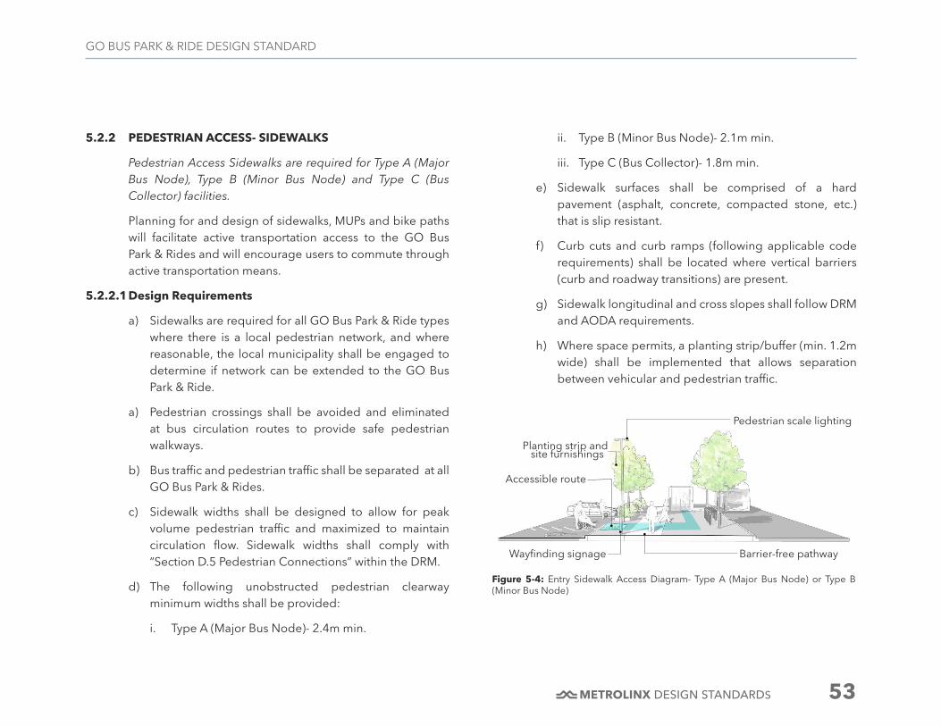
DESIGN STANDARDS 53
GO BUS PARK & RIDE DESIGN STANDARD
5.2.2 PEDESTRIAN ACCESS- SIDEWALKS
Pedestrian Access Sidewalks are required for Type A (Major Bus Node), Type B (Minor Bus Node) and Type C (Bus Collector) facilities.
Planning for and design of sidewalks, MUPs and bike paths will facilitate active transportation access to the GO Bus Park & Rides and will encourage users to commute through active transportation means.
5.2.2.1 Design Requirements
a) Sidewalks are required for all GO Bus Park & Ride types where there is a local pedestrian network, and where reasonable, the local municipality shall be engaged to determine if network can be extended to the GO Bus Park & Ride.
a) Pedestrian crossings shall be avoided and eliminated at bus circulation routes to provide safe pedestrian walkways.
b) Bus traffic and pedestrian traffic shall be separated at all GO Bus Park & Rides.
c) Sidewalk widths shall be designed to allow for peak volume pedestrian traffic and maximized to maintain circulation flow. Sidewalk widths shall comply with “Section D.5 Pedestrian Connections” within the DRM.
d) The following unobstructed pedestrian clearway minimum widths shall be provided:
i. Type A (Major Bus Node)- 2.4m min.
ii. Type B (Minor Bus Node)- 2.1m min.
iii. Type C (Bus Collector)- 1.8m min.
e) Sidewalk surfaces shall be comprised of a hard pavement (asphalt, concrete, compacted stone, etc.) that is slip resistant.
f) Curb cuts and curb ramps (following applicable code requirements) shall be located where vertical barriers (curb and roadway transitions) are present.
g) Sidewalk longitudinal and cross slopes shall follow DRM and AODA requirements.
h) Where space permits, a planting strip/buffer (min. 1.2m wide) shall be implemented that allows separation between vehicular and pedestrian traffic.
Wayfinding signage
Accessible route
Pedestrian scale lighting
Planting strip and
Barrier-free pathway
Figure 5-4: Entry Sidewalk Access Diagram- Type A (Major Bus Node) or Type B (Minor Bus Node)
site furnishings

DESIGN STANDARDS 54
GO BUS PARK & RIDE DESIGN STANDARD
5.2.3 PEDESTRIAN ACCESS- MULTI-USE PATHS (MUP)
Multi-Use Paths (MUP) are required for Type A (Major Bus Node) facilities and shall be applied as required for Type B (Minor Bus Node) and Type C (Bus Collector) facilities.
Off-Road Multi-Use Paths (MUP) or Shared Pathways are an effective way to allow for higher volume pedestrian travel within one pedestrian pathway.
5.2.3.1 Design Requirements
a) Multi-Use Paths are required for all GO Bus Park & Ride types where there is a local pedestrian network, and where reasonable, the local municipality shall be engaged to determine if the network can be extended to the site.
b) The layout of the MUP, clear distances and stopping distances shall follow applicable code requirements.
c) The width of the MUP shall allow for two-way travel, either pedestrian or cyclists, which minimizes conflicts and creates perceived lanes of travel.
d) MUP longitudinal and cross slopes shall follow DRM requirements.
e) Planting improvements shall be included along the MUP to enhance the customer’s experience.
f) Resting and viewing areas along longer paths of travel to the shelter location shall be planned for and included within the MUP, except where demonstrated not possible.
Accessible route
Pedestrian scale lighting
Planting strip
Barrier-free pathway
Figure 5-5: Entry Sidewalk Access Diagram- Type C (Bus Collector)
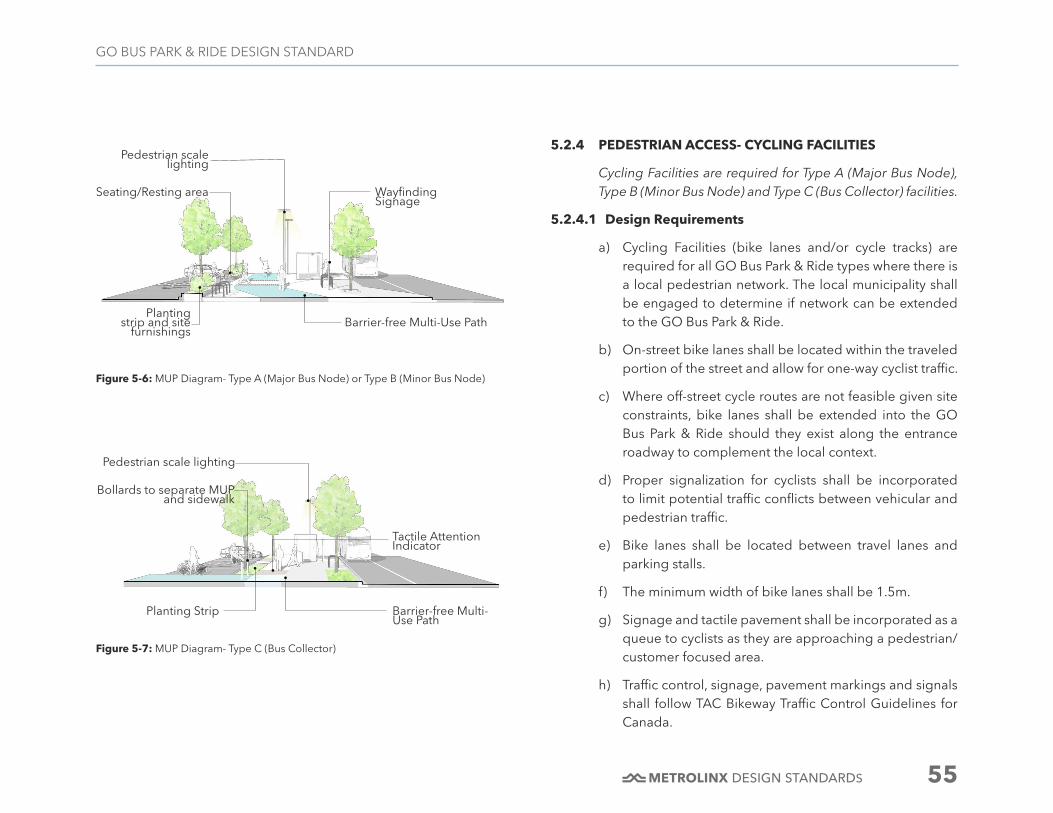
DESIGN STANDARDS 55
GO BUS PARK & RIDE DESIGN STANDARD
5.2.4 PEDESTRIAN ACCESS- CYCLING FACILITIES
Cycling Facilities are required for Type A (Major Bus Node), Type B (Minor Bus Node) and Type C (Bus Collector) facilities.
5.2.4.1 Design Requirements
a) Cycling Facilities (bike lanes and/or cycle tracks) are required for all GO Bus Park & Ride types where there is a local pedestrian network. The local municipality shall be engaged to determine if network can be extended to the GO Bus Park & Ride.
b) On-street bike lanes shall be located within the traveled portion of the street and allow for one-way cyclist traffic.
c) Where off-street cycle routes are not feasible given site constraints, bike lanes shall be extended into the GO Bus Park & Ride should they exist along the entrance roadway to complement the local context.
d) Proper signalization for cyclists shall be incorporated to limit potential traffic conflicts between vehicular and pedestrian traffic.
e) Bike lanes shall be located between travel lanes and parking stalls.
f) The minimum width of bike lanes shall be 1.5m.
g) Signage and tactile pavement shall be incorporated as a queue to cyclists as they are approaching a pedestrian/customer focused area.
h) Traffic control, signage, pavement markings and signals shall follow TAC Bikeway Traffic Control Guidelines for Canada.
Figure 5-6: MUP Diagram- Type A (Major Bus Node) or Type B (Minor Bus Node)
Figure 5-7: MUP Diagram- Type C (Bus Collector)
Wayfinding Signage
Seating/Resting area
Pedestrian scale lighting
Planting strip and site
furnishingsBarrier-free Multi-Use Path
Bollards to separate MUP and sidewalk
Pedestrian scale lighting
Planting Strip Barrier-free Multi-Use Path
Tactile Attention Indicator

DESIGN STANDARDS 56
GO BUS PARK & RIDE DESIGN STANDARD
Figure 5-8: Bike Path Diagram
Wayfinding signage
Raised curb separation
Planting strip and site furnishings
1.5m minimum width
Figure 5-9: Bike Path and Sidewalk Intersection
Bicycle Dismount Sign
Multi-use Path
Sidewalk
Tactile Attention Indicators

DESIGN STANDARDS 57
GO BUS PARK & RIDE DESIGN STANDARD
5.3 SITE FURNISHING
5.3.1 EXTERIOR SEATING
Exterior Seating is required for Type A (Major Bus Node) facilities and shall be applied as required for Type B (Minor Bus Node) and Type C (Bus Collector) facilities.
Depending on site conditions, exterior seating (excluding seating in shelters) may be required at GO Bus Park & Rides. Where possible, incorporating seating in other forms than stand-alone benches and integrating seating into site features (seatwalls, armour stone, etc.) is a powerful multi-functional approach that provides space saving techniques and minimizes costs associated with standalone benches.
5.3.1.1 Design Requirements
a) Seating shall be added at areas within a site that have been determined to be waiting and/or resting areas that are outside of the shelter platform and DWAs.
b) Exterior seating shall comply with the requirements outlined by DS-02 Universal Design Standard.
c) Seating shall be provided every 30 metres, and located adjacent to the main accessible pedestrian path of travel with a minimum of 500mm offset.
d) Accessible seating areas shall be located at the ends of benches, and shall comply with relevant sections of the DS-02 Universal Design Standard.
e) Bench surface and back materials used shall have a low ability for heat retention. Suitable materials include:
high-density, FSC certified wood; HDPE; HDPC; etc. Metal seating surfaces shall be prohibited.
f) Seating shall be located in areas that promote a comfortable microclimate in all seasons.
g) Anti-vagrant measures shall be added to bench surfaces that prohibit laying and/or sleeping.
h) Accessible seating areas shall be located at the ends of benches (min. 900mm wide and 1500mm long) as per the DS-02 Universal Design Standard.
i) Accessible seating areas shall enable persons who use wheelchairs to sit alongside other seated users (i.e. so that the back of the wheelchair is aligned with the backrest of the benches).
j) Where seating is demonstrated possible, the GO Standard Bench shall be referenced.
Figure 5-10: Exterior Seating
0.5m
min

DESIGN STANDARDS 58
GO BUS PARK & RIDE DESIGN STANDARD
5.3.2 WASTE AND RECYCLING RECEPTACLES
Waste and Recycling Receptacles are required for Type A (Major Bus Node), Type B (Minor Bus Node) and Type C (Bus Collector) facilities.
5.3.2.1 Design Requirements
a) Two-Three (minimum) receptacles shall be provided for Type A (Major Bus Node) and Type B (Minor Bus Node) sites and one (minimum) receptacle for Type C (Bus Collector) sites.
b) A garbage bin enclosure (applicable size depends on site specifics) shall be provided at each GO Bus Park & Ride.
c) The garbage bin enclosure shall shield views to the garbage bin and comply with the requirements set forth in the DRM.
d) Receptacle style and dimensions shall be provided based on local municipality and/or service provider and per Metrolinx Standards and the DRM.
e) Tri-waste receptacles are preferred to allow for disposal of bottles/cans, paper and trash.
f) Placement shall be in high visibility areas such as Designated Waiting Areas and pedestrian pathways.
g) Waste receptacle placement shall be easily accessible and highly visible pertaining to seating/resting area locations.
h) Visibility shall be provided through transparency to the interior of the receptacle.
i) A hood or top shall be provided to ensure weather protection to the receptacle opening.
Figure 5-11: Tri-Waste Receptacle Diagram
0.5m m
in

DESIGN STANDARDS 59
GO BUS PARK & RIDE DESIGN STANDARD
5.4 SITE BARRIERS
5.4.1 GENERAL
In order to restrict pedestrian and/or vehicular access within the site, or to minimize sound impacts both on site and off site, the use of vertical barriers is an effective approach. There are several types of barriers that may be utilized depending on the location within the site and the intent of the physical barrier.
5.4.2 FENCING
Fencing shall be applied as required for Type A (Major Bus Node), Type B (Minor Bus Node) and Type C (Bus Collector) facilities.
5.4.2.1 Design Requirements
a) General
i. Decorative types of fencing shall be used in public facing areas of the GO Bus Park & Ride.
ii. Fencing shall be placed to not obstruct pedestrian/cyclist direct pathways.
iii. Utilitarian types of fencing, such as a chain link fence, shall be prohibited.
iv. A clear line of sight shall be provided to and from public areas within the site
b) Size
i. Fences shall have a maximum height of 1.2m.
c) Colour/Finish
i. Fences shall have a medium to dark grey colour/finish to minimize visual impacts on the surrounding context.
d) Planting
i. A planting buffer shall be provided along the fence line to soften the visual effect.
ii. The planting buffer shall be a minimum of 1.2m wide.
Figure 5-12: Decorative Metal Fencing
1.2
m

DESIGN STANDARDS 60
GO BUS PARK & RIDE DESIGN STANDARD
5.4.3 BOLLARDS
Bollards shall be applied as required for Type A (Major Bus Node), Type B (Minor Bus Node) and Type C (Bus Collector) facilities.
5.4.3.1 Design Requirements
a) Location
i. Bollards shall be placed in areas to prohibit automobile traffic and integrated into pedestrian and vehicular circulation routes within the site.
ii. Proper clearances shall be provided for bus swept path at bus platform location.
iii. The offset distance from bollard row to back of curb shall be 500mm minimum.
iv. Bollards shall be placed so that the edge to edge distance (opening) meets accessibility requirements per the DS-02 Universal Design Standard, while not impacting the bollards intended use to prohibit vehicular traffic.
b) Colour/Finish
i. Bollards shall have a 304 grade stainless steel w/Satin finish.
c) Type
i. Bollards shall be either fixed or removable, depending on vehicular access requirements.
Figure 5-13: Bollard Diagram
0.5 m m
in
1.2 m min(clear width)

DESIGN STANDARDS 61
GO BUS PARK & RIDE DESIGN STANDARD
5.4.4 RETAINING WALLS
Retaining Walls shall be applied as required for Type A (Major Bus Node), Type B (Minor Bus Node) and Type C (Bus Collector) facilities.
5.4.4.1 Design Requirements
b) Design
i. Retaining walls shall be consistent in their appearance throughout all GO Bus Park & Ride types.
ii. Retaining walls that abut property lines and right-of-ways perpendicularly shall be minimized in height, with a maximum 600mm height accepted.
iii. Where pedestrian walkways are adjacent to retaining walls and there is an immediate fall concern greater than 600mm, a guardrail (meeting code requirements) shall be installed on top of the retaining wall or before the retaining wall on the walkway side.
iv. Guardrail design shall be low profile and complementary to the architectural elements of the site.
v. Provisions shall be made for proper drainage behind the wall and drains or weep holes where required.
c) Materials
i. Wood is not an acceptable material for retaining walls
ii. Long expanses of concrete retaining walls shall have reveals.
iii. Concrete retaining walls, either precast or cast-in-place, which are public facing, shall be light sandblasted.
iv. Decorative formliners or embossed patterns for cast-in-place walls shall be included to add interest to the wall face design, where required.
v. All retaining walls shall have graffiti protection coating, either applied by manufacturer or applied on site.
vi. Low retaining walls (less than 1.5m height) shall be precast concrete units.
vii. Gabion walls are permitted for use in non-public facing areas.
d) Code Requirements
i. Building Code requirements (local, provincial and federal) shall be implemented.
Figure 5-14: Retaining Wall Diagram

DESIGN STANDARDS 62
GO BUS PARK & RIDE DESIGN STANDARD
5.4.5 TRAFFIC BARRIERS
Traffic Barriers shall be applied as required for Type A (Major Bus Node), Type B (Minor Bus Node) and Type C (Bus Collector) facilities.
In order to restrict circulation paths for both automobiles and buses, there are several forms of traffic barriers.
5.4.5.1 Design Requirements
b) The aesthetic of traffic barriers shall be complementary to the site’s architectural character.
c) Depending on the site’s design characteristics, intent for barrier and space limitations, the following acceptable traffic barriers shall be used:
i. Prefabricated raised planters
ii. Bollards
iii. Decorative Guardrails
iv. Armour Stone
v. Prefabricated curbs (including curb stops at parking locations)
d) The following traffic barriers shall be prohibited for use at GO Bus Park & Rides:
i. Concrete jersey barriers
ii. Traffic Cones
iii. Delineator Posts
iv. Flexible Posts
v. Traffic Barricades
vi. Safety Fence

DESIGN STANDARDS 63
GO BUS PARK & RIDE DESIGN STANDARD
5.4.6 SOUND ATTENUATION WALLS
Sound Attenuation Walls shall be applied as required for Type A (Major Bus Node), Type B (Minor Bus Node) and Type C (Bus Collector) facilities.
To restrict on-site noise and mitigate or control off-site impacts and noise pollution to GO Bus Park & Rides, the use of sound attenuation walls may be required. The walls also prohibit undesirable views and provide a level of security.
5.4.6.1 Design Requirements
b) Design
i. Sound attenuation walls shall be consistent in its appearance throughout all GO Bus Park & Ride types.
c) Location
i. Sound attenuation walls shall be placed closest to the noise source to increase effectiveness.
ii. Sound attenuation walls shall be placed adjacent to residential neighborhood sites.
iii. Sound attenuation walls shall be placed within close proximity to bus stop and bus standing locations.
iv. Sound attenuation walls shall be placed along major highways (400 series) to separate customer facing areas (bus platform, DWAs, etc.) and roadway traffic noise.
v. Where required, an integrated retaining and sound attenuation wall approach shall be designed.
d) Materials
i. Shall be durable and low maintenance.
ii. Shall be either a precast concrete patterned wall or transparent wall (glass, acrylic material)
iii. Shall include graffiti protection coating along the wall face
Figure 5-15: Sound Attenuation Diagram

DESIGN STANDARDS 64
GO BUS PARK & RIDE DESIGN STANDARD
5.5.2 BUS LOOP LIGHTING
5.5.2.1 Design Requirements
a) Bus loops shall provide a line of full cut-off single-headed downlights on lampposts aligned with the back of bus shelters.
b) Lighting shall comply with the requirements of the DRM.
c) Lamppost height shall be kept to a minimum.
d) Maximum height for poles shall not exceed 30m.
e) Increased lighting levels shall be provided at DWA locations.
f) Colour temperature shall comply with the DRM.
5.5 SITE LIGHTING
Site Lighting required for Type A (Major Bus Node), Type B (Minor Bus Node) and Type C (Bus Collector) facilities.
5.5.1 GENERAL
Ample lighting will enhance safety and strengthen the customer experience.
5.5.1.1 Design Requirements
a) Ensure lighting levels are as uniform across the site to the greatest extent possible.
b) Lighting coverage shall eliminate dark spots, and where required, be coordinated with the municipality so that illumination and light spreads minimize overlaps and contrasts.
c) Ensure placement of site lighting is shielded from glare and light pollution on adjacent neighbouring properties.
d) Lighting shall comply with the DRM and Metrolinx Standard Drawings and Specifications.
e) GO Bus Park & Rides shall be well lit from both a vehicular and pedestrian perspective.
Figure 5-16: Bus Loop Lighting Diagram

DESIGN STANDARDS 65
GO BUS PARK & RIDE DESIGN STANDARD
5.5.3 SURFACE PARKING LIGHTING
5.5.3.1 Design Requirements
a) The lighting for surface parking and drive aisle areas shall be provided by full cut-off single and double-headed downlights on lampposts.
b) Lighting shall comply with the requirements of the DRM.
c) Lamppost height shall be kept to a minimum.
d) Maximum height for poles shall not to exceed 30m.
e) Colour temperature shall comply with the DRM.
Figure 5-17: Parking Lot Lighting Diagram
Figure 5-18: PUDO Lighting Diagram

DESIGN STANDARDS 66
GO BUS PARK & RIDE DESIGN STANDARD
5.6 PEDESTRIAN SCALE LIGHTING
Pedestrian Scale Lighting is required for Type A (Major Bus Node), Type B (Minor Bus Node) and Type C (Bus Collector) facilities.
5.6.1 GENERAL
Lighting of pedestrian circulation routes plays an integral role to the safety and functionality at the GO Bus Park & Ride. Inclusion of pedestrian scale type lighting is to be designed at path, waiting, seating and pedestrian prominent locations throughout the GO Bus Park & Ride.
5.6.1.1 Design Requirements
a) Pedestrian scale lighting including light standards, light bollards and plant lighting shall be designed to:
i. Meet dark sky standards
ii. Be aimed downwards to avoid light pollution
iii. Placed and shielded to reduce glare and light on adjacent neighbouring properties
b) Light levels shall comply with the DRM.
c) Light pole height shall not exceed 6.0m.
d) Luminaire shall be LED light type, as LED greatly increases life expectancy and reduces maintenance and operational costs.
e) Illumination shall be designed to provide visual comfort and minimum glare for pedestrians and motorists alike.
f) Lighting shall be integrated into built site elements; site furnishings; wayfinding signage; etc. to strengthen the feel and comfort of pedestrian spaces, except where demonstrated not possible.
g) Light bollards shall be used for pathway lighting, except where demonstrated not possible.
h) Planting bed lighting shall be positioned to effectively light the pedestrian pathway.
Figure 5-19: Pedestrian Scale Lighting Diagram
Pedestrian scale lighting
Tree canopy down lights
Light bollard to delineate pedestrian path of travel

DESIGN STANDARDS 67
GO BUS PARK & RIDE DESIGN STANDARD
5.7 PLANTING DESIGN REQUIREMENTS
5.7.1 GENERAL
Green space provides measurable benefits that are vital to the overall health of the GO Bus Park & Ride and neighboring communities.
5.7.1.1 Design Requirements
a) Planting strategies shall be consistent, resilient, sustainable, adaptable and create identity.
b) The planting design shall conform to the DRM and GO Sustainable Design Standard, and follow local governing agency requirements.
c) Plantings selected for the GO Bus Park & Ride shall contain only native species. Up to 50% introduced (non-native) species may be proposed in areas with restricted or harsh planting conditions and that do not have a direct connection to a natural heritage system. Invasive species shall not be proposed.
d) All plant material shall be salt-resilient, drought-tolerant and native/ adaptive/ non-invasive/ hardy species, with a mix of deciduous and conifer plant types. Ensuring that these requirements are met will strengthen the local ecology and contribute to the success of the surrounding plant community.
e) Where directed by Metrolinx, non-freeze type hose bibs shall be provided in flush mounted boxes with locking covers at bus platform locations for maintenance purposes, sized to suit the site requirement.
5.7.2 TREES
Trees are required for Type A (Major Bus Node) and Type B (Minor Bus Node) and shall be applied as required for Type C (Bus Collector) facilities.
Trees provide shade and create buffers within a site, also managing the stormwater and reducing urban heat island effect. Placement of trees can provide visual order as well as dictate site lines that are an essential organizational and orientation device used to get to and from the shelter platform.
5.7.2.1 Design Requirements
a) Location
i. Trees shall be provided along pedestrian access routes and near passenger waiting areas to enhance the customer experience and comfort level.
ii. Trees shall be placed in proximity to shelters and passenger waiting areas to offer natural shading from summer weather.
iii. Branching shall not interfere with vehicular circulation patterns and with CPTED principles of natural surveillance.
iv. Visibility and sight line requirements at intersections shall be maintained.
v. Appropriate species that keep their form to maintain clear visibility shall be planted.

DESIGN STANDARDS 68
GO BUS PARK & RIDE DESIGN STANDARD
vi. Coniferous plant material shall be introduced where visual screening is appropriate.
vii. Native plant material with ecological compatibility, appropriate for site conditions (e.g. salt and drought tolerant) shall be utilized.
viii. Strategic planting shall be used to maintain and enhance pedestrian circulation connections from off site to the DWA.
ix. The tree planting zone shall have a minimum soil depth of 1.0m, with 1.2m preferred.
x. Soil trenches shall be connected so that they are continuous either below or above grade, except where deomonstrated not possible.
b) Spacing Between Trees
i. Spacing of trees shall be based on the size and form of the tree species at maturity.
ii. In general, tree spacing shall range from 8 to 10 metres, unless otherwise regulated by local municipalities.
iii. Designers shall consider alternative tree planting schemes that are compatible with the site context, when demonstrated possible.
c) Soil Volumes
i. Local municipality recommended soil volumes shall be maintained. At a minimum, the soil volumes shown below shall be provided for all tree plantings:
1. Small Trees: 3m mature canopy diameter, 8-11 m3
2. Medium Trees: 5m mature canopy diameter, 20-23 m3
3. Large Trees: 8m mature canopy diameter, 30m3 for each tree planted individually or 20m3 in a shared bed
d) Offset from Curb
i. Preference shall be given for the offset from curb to follow the minimum distances for fixed objects as defined in the Roadside Safety Manual to allow for snow storage.
ii. A tree species’ salt tolerance shall also be of concern when considering the offset from curb.
e) Offset From Intersections and Entrances
i. Sight distance triangles shall be maintained free of tree trunks and branches.
ii. To maintain minimum sight line distances the following offsets shall be followed:
1. Trees shall not be planted within 9.0 metres of an intersection
2. Trees shall not be planted within 3.0 metres of an entranceway or driveway
iii. The local municipality's requirements surrounding planting design and other landscaping elements within sight triangles shall be referenced for specific design criteria.

DESIGN STANDARDS 69
GO BUS PARK & RIDE DESIGN STANDARD
f) Offset From Sidewalk and Property Boundaries
i. Street trees shall be planted to minimize conflicts with sidewalk construction and maintenance.
ii. To allow for sidewalk construction and maintenance the following offsets shall be followed:
1. Trees shall be planted a minimum of 1.0 metres from edge of sidewalk, a 1.5 metre offset is preferred.
2. Trees shall be planted a minimum of 1.0 metres from property boundaries.
g) Offset from Ditches and Drainage
i. Trees shall not be located within 1.0 metre of the ditch line in order to allow for maintenance of the ditch.
ii. Trees shall not be planted where water may collect and temporarily pool.
h) Offset from Utilities
i. Tree placement shall follow specified criteria regarding horizontal and vertical clearance distances by governing utility companies.
ii. Tree shall not be planted within the right-of-way, in streetscape conditions which front undeveloped properties or in areas where future grade changes are anticipated.
i) Species Selection
i. Diversity shall be created at the urban forest level allowing for the creation of aesthetically pleasing landscapes in both the immediate platform and the GO Bus Park & Ride. This design approach supports Metrolinx's commitment to maintaining a healthy urban forest and encouraging biodiversity.
Figure 5-20: Street Tree Planting in Grates

DESIGN STANDARDS 70
GO BUS PARK & RIDE DESIGN STANDARD
Figure 5-21: Street Tree Planting in Open Pits
Figure 5-22: Tree Planting in Raised Planter
Figure 5-23: Bioswale

DESIGN STANDARDS 71
GO BUS PARK & RIDE DESIGN STANDARD
5.7.3 SHRUBS / ORNAMENTAL GRASSES
Shrubs are required for Type A (Major Bus Node) and Type B (Minor Bus Node) and shall be applied as required for Type C (Bus Collector) facilities.
Shrubs and ornamental grass species contribute to a resilient and sustainable planting community and also contribute to the walkability and pedestrian experience by providing seasonal interest, and protection.
5.7.3.1 Design Requirements
a) The selected shrubs/ornamental grass species shall both complement the existing surrounding context and emphasize the tree line as a significant site feature.
b) The planting zone shall have a minimum soil depth of 0.6 m.
c) The selected species shall promote diversity and shall be low maintenance.
d) Groundcover/seeding/sodding shall contain at least 50% native species that are suitable to the local soil, moisture, and light condition.
e) Proposed percentages in the seeding mix for each species shall be provided.
f) All disturbed areas shall be seeded as soon as possible following the completion of construction.
g) In general, a minimum of 15 cm of topsoil shall be applied to disturbed areas prior to seeding/sodding applications.
Figure 5-25: Shrub Planting in Bioswale
Figure 5-24: Shrub Planting in Planter

DESIGN STANDARDS 72
GO BUS PARK & RIDE DESIGN STANDARD
5.7.4 GROUNDCOVERS / SEEDING / SODDING
Groundcover / Seeding / Sodding are required for Type A (Major Bus Node), Type B (Minor Bus Node) and Type C (Bus Collector) facilities.
Groundcovers are required to restore and stabilize disturbed soils. Unacceptable mixes can undermine the ecological integrity when the mix is not suited to the site conditions and fails to stabilize soils.
5.7.4.1 Design Requirements
a) Groundcover/seeding/sodding shall contain at least 50% native species that are suitable to the local soil, moisture, and natural sunlight exposure.
b) Sodding shall only be utilized in small areas (1.0m-2.0m width) with adjacent hardscape surfaces. For example, sod is acceptable at areas of disturbance that require a “greening” impact to tie into existing grassed areas, which are adjacent to proposed sidewalks and pathways. Moreover, areas that require immediate erosion control and/or slope stabilization measures may be considered for sodding.
c) Terraseeding shall be utilized for larger softscape type areas, due to lower operational costs and expanded grass choices.
d) In the seeding mix that is proposed the percentages for each species in the mix shall be provided.
e) All disturbed areas shall be seeded as soon as possible following the completion of construction.
Figure 5-26 Shrub Planting Providing Visual Buffer
DESIGN STANDARDS 73
GO BUS PARK & RIDE DESIGN STANDARD
f) Seeding/Sodding is prohibited under car overhangs and a 1.0m wide kill strip shall be provided at perimeter parking stalls.
g) In general, a minimum of 15 cm of topsoil shall be applied to disturbed areas prior to seeding/sodding applications.
Figure 5-27: Sidewalk Sod Restoration

DESIGN STANDARDS 74
GO BUS PARK & RIDE DESIGN STANDARD
6 PASSENGER AMENITIES & ANCILLARY FACILITIES
6.1 OVERVIEW
Adding to the customer experience by providing safe, secure and intuitive passenger amenities will further define the success of a GO Bus Park & Ride. Accessibility is to be a top priority when locating amenities and ancillary facilities. Clear sight lines aided by strategically placed wayfinding signage will enhance the customer’s journey throughout the GO Bus Park & Ride from Access, to Arrival, to Platform and finally Connection.
6.2 PASSENGER SHELTER
Passenger Shelters are required for Type A (Major Bus Node), Type B (Minor Bus Node) and Type C (Bus Collector) facilities.
6.2.1 GENERAL
Shelters are a key customer amenity at GO Park & Rides and are intended to serve all customers and maximize customer
6.2.1.1 Design Requirements
a) Passenger shelters, including all required lighting, electric radiant heater, and other requirements shall be as specified in the GO Shelter Standard.
b) The passenger shelters shall be designed to:
i. Provide maximum customer comfort and protection from rain, wind, snow and sun.
ii. Conform to the GO Shelter Drawings and Specifications;
iii. Be at least 3 metres away from edge of curb, to accommodate accessible boarding and alighting from buses; and
iv. Conform to the DS-02 Universal Design Standard and the DRM.
c) Shelter types shall be applied at each type of GO Bus Park & Ride as per Table 6-1, below:
TYPE A (MAJOR BUS
NODE)
TYPE B (MINOR BUS
NODE)
TYPE C (BUS COLLECTOR)
Shelter Type Type 1 Type 2 Type 3
Table 6-1: Shelter Type based on GO Bus Park & Ride Classification

DESIGN STANDARDS 75
GO BUS PARK & RIDE DESIGN STANDARD
The following illustrations depict the typical shelter types for GO Bus Park & Rides:
6.3 FARE DEVICE
Fare Devices are required for Type A (Major Bus Node) and shall be applied as required for Type B (Minor Bus Node) and Type C (Bus Collector) facilities.
6.3.1 GENERAL
Fare Devices are touchscreen-based ticketing machines which shall enable passengers to purchase tickets for their commute in addition to supporting reloading of passenger’s Presto cards for the top-up balance. The Fare Device is required to be Presto-enabled in order to replace the need for a separate Add Value Machine (AVM). Fare Devices are essential to ease the process of ticketing, and to enhance and automate the passenger experience. Presto is the electronic payment card that can be used as a method of payment for using local transit services in Greater Toronto and Hamilton Area and Ottawa, thus eliminating the need of cash, tokens, tickets or passes.
6.3.1.1 Design Requirements
a) Fare Devices are required at Type 1- Large Passenger Shelters. For Type 2- Medium Passenger Shelters and Type 3- Small Passenger Shelters, alternative fare payment mechanisms, such as payment on bus etc., shall be considered.
b) Fare Devices shall support the functionality of Presto and together, they form a part of the revenue management system for GO Bus Park & Rides.
c) Fare Devices shall be housed in a steel enclosure and
Figure 6-1: Typical Shelter Type Illustrations
1
2
3
Type 1- Large Passenger Shelter
Type 2- Medium Passenger Shelter
Type 3- Small Passenger Shelter

DESIGN STANDARDS 76
GO BUS PARK & RIDE DESIGN STANDARD
include colour, logos and branding, except where demonstrated not possible.
d) Technical requirements associated with the Fare Device shall comply with the guidelines and requirements of Presto and the DRM.
e) Fare Devices shall have a bright and user-friendly interface.
f) Fare Devices shall be modular in nature and shall have the capability of including any future modification, upgradations and iterations when they are available.
6.4 INTERNET
6.4.1 WI-FI
Wi-Fi is required for Type A (Major Bus Node) facilities and shall be applied as required for Type B (Minor Bus Node) and Type C (Bus Collector) facilities.
Availability of wireless broadband internet service has become an essential component in enhancing digital connectivity. Devices such as cell phones, laptops and tablets can connect with the Wi-Fi service for Internet browsing or any other connectivity needs. Additionally, Wi-Fi may also act as the backhaul for wireless communication between facility operators and also in supporting connectivity requirements of any future IoT devices implemented at the facility. Wi-Fi infrastructure is typically comprised of a combination of Wi-Fi Access Points (APs), mounting infrastructure, and associated active and passive infrastructure.
6.4.1.1 Design Requirements
a) Wi-Fi APs shall be installed in the facility to allow mobile devices to connect to the Wi-Fi service.
b) Installation of Wi-Fi APs shall be undertaken in a way that is aesthetically pleasing, unobtrusive and in-line with the design and architectural guidelines of Metrolinx and the facility.
c) As per the finalized design, Wi-Fi APs shall be installed on walls or ceilings.
d) Wi-Fi services shall be provided across strategic locations at the facility, with the most prominent being the DWA and common areas.

DESIGN STANDARDS 77
GO BUS PARK & RIDE DESIGN STANDARD
ii. Bike parking facilities shall be located in the immediate vicinity of the platform shelter and/or Designated Waiting Area.
iii. Bike parking facilities shall be in highly visible locations near primary pedestrian routes.
iv. Bike parking facilities shall be a maximum distance of 10m from the terminus of bikeway facilities, with a barrier-free access pathway from the bikeway facilities.
v. Bike parking shall not be located along “accessible” routes, to minimize potential conflicts between pedestrians and cyclists.
c) Signage and Wayfinding
i. A consistent signage approach for the site shall incorporate the bike parking facilities.
ii. Signage shall be placed at bike path and bike lane entrances to the site, advertising that bike parking is available near the Designated Waiting Areas and shall direct users to the bike parking locations.
6.5.2 OPEN BIKE STORAGE
Open Bike Storage is required for Type A (Major Bus Node), Type B (Minor Bus Node) and Type C (Bus Collector) facilities.
Bike racks both individual and combined styles allow for a non-covered location for bikes to be secured by transit visitors at GO Bus Park & Rides.
6.5 BIKE SHELTER
6.5.1 GENERAL
Bike parking is an integral part of a successful pedestrian circulation route and is necessary to encourage cycling as an active transportation mode. Bike parking provide passengers with an attractive, convenient and user-friendly solution for passengers to secure their bikes at the GO Bus Park & Ride before embarking on their transit trip.
Bike storage may be intended for short term or long term use, depending on the transit user’s trip duration.
6.5.1.1 Design Requirements
a) Short Term vs. Long Term Bike Parking
i. Short term bike parking shall be provided for uses 4 hours or less and shall:
1. Be unsheltered
2. Be located within 30m of the bus shelter.
iii. Long term bike parking shall be provided for uses exceeding 4 hours and shall:
1. Include bike lockers and/or enclosed shelters.
2. Be located within 30m of any Designated Waiting Area (DWA).
b) Preferred Location of Bike Parking Facilities
i. Bike parking facilities shall be located and installed as per the DS-07 Bike Infrastructure Design Standard, GO Bike Shelter Standard and GO Rail Station Access Plan.

DESIGN STANDARDS 78
GO BUS PARK & RIDE DESIGN STANDARD
6.5.2.1 Design Requirements
a) Bike Rack Materiality
i. Bike racks shall comply with the “Essentials of Bike Parking,” published by the Association of Pedestrian and Bicycle Professionals (APBP).
ii. Bike Racks shall comply with the DS-07 Bike Infrastructure Design Standard.
iii. Bike rack styles that are listed in the “Racks to Avoid” section of the above reference document shall be prohibited.
iv. Approved Materials for use shall be as follow:
1. Steel – galvanized
2. Steel – powder coat
3. Steel – thermoplastic
4. Stainless steel
v. Bike rack materials and colours shall be selected to match the design vision while maximizing durability.
vi. Non-corrosive materials shall be specified.
vii. Bike racks shall provide 2-points of contact to the bike frame which will stabilize the bicycle and allow for various locations for a bike U-shaped or similar lock to be used.
b) Bike Rack Layout
i. Bike racks shall be located on hardscaped (paving) surfaces.
ii. Covered bike racks shall be considered in appropriate locations to encourage cycling.
iii. Bike rack parking shall be situated in locations where overhead canopy structures could potentially be utilized for weather protection purposes.
iv. Bike racks shall be located adjacent sidewalks to ensure that no portion of the parked bicycle extends into the path of travel. A minimum of 500mm offset distance shall be provided.
v. Bike Racks shall be located away from the “accessible” route, and the open bike storage locations must be cane-detectable and color contrasting (at least 50 Light Reflectance Value point difference) with ground surface treatment for customers with visual impairments.
Figure 6-2: Type A (Major Bus Node) or Type B (Minor Bus Node) Open Bike Storage- 12 Bike Capacity, minimum
0.5 m min

DESIGN STANDARDS 79
GO BUS PARK & RIDE DESIGN STANDARD
6.5.3 COVERED BIKE STORAGE
Covered Bike Storage is required for Type A (Major Bus Node) facilities and shall be applied as required for Type B (Minor Bus Node) and Type C (Bus Collector) facilities.
Standalone bike lockers or shelters are generally utilized for long term parking and offer a degree of weather protection. To decrease necessary shelter size, it is recommended that combined style bike racks are provided. GO Type 4 shelter or approved (through consultation with Metrolinx Design Division) canopy will be required.
6.5.3.1 Design Requirements
a) Standalone Covered Bike Storage shall comply with DS-07 Bike Infrastructure Design Standard.
b) The GO Shelter Standard shall be referred to for specifics regarding components of the bike shelter and sizing.
c) Bike shelter lighting levels shall comply with the DRM.
d) Shelters shall be mounted to a concrete slab foundation on grade.
e) Pavement at entrance to shelter shall be barrier-free.
Figure 6-4: Bike Rack Layout Figure 6-5: Covered Bike Storage Station
0.5
m m
in
2.4
m
(1.8
m m
in)
2.4
m
(1.8
m m
in)
0.5
m
0.9 m
0.9 m(0.6m min)
1.5
m
(1.2
m m
in)
Plan
ter
Figure 6-3: Type C (Bus Collector) Open Bike Storage- 4 bike capacity, minimum
0.5 m min

DESIGN STANDARDS 80
GO BUS PARK & RIDE DESIGN STANDARD
6.5.4 SECURE BIKE STORAGE
Secure Bike Storage is required for Type A (Major Bus Node) facilities and shall be applied as required for Type B (Minor Bus Node) and Type C (Bus Collector) facilities.
Depending on site conditions, Secured Bike Storage facilities may be required at GO Bus Park & Rides. Secured bike storage adds a level of comfort and confidence that a user’s bicycle will be secured until they return.
6.5.4.1 Design Requirements
a) Secured Bike Storage facilities, if provided, shall comply with the DS-07 Bike Infrastructure Design Standard.
6.5.5 BIKE SHARE INTEGRATION
Bike Share Integration shall be applied as required for Type A (Major Bus Node), Type B (Minor Bus Node) and Type C (Bus Collector) facilities.
6.5.5.1 Design Requirements
a) Bike Share facilities, if included, shall be installed and located to comply with the GO Rail Station Access Plan.
Figure 6-6: Secure Bike Storage- 16 Bike Capacity, as per the DS-07 Bike Infrastructure Design Standard

DESIGN STANDARDS 81
GO BUS PARK & RIDE DESIGN STANDARD
g) During design review, Third Party Advertising and Design Division (RT Design Implementation) Subject Matter Experts (SMEs) shall be included for consultation.
h) Shall coordinate with Metrolinx I&IT, Design Division, and Non Fare Sales, Advertising Manager during planning and design implementation.
i) Advertising panels shall comply with the DS-04 GO Station Architecture Standard, DS-03 MTX Wayfinding Design Standard, DS-03 P1 Metrolinx Sign Implementation Manual: GO Transit Edition, GO Shelter Standard and DS-02 Universal Design Standard.
j) Advertising panel and device typologies, design and sizes shall follow the requirements summarized in Table 6-2, below.
6.6 ADVERTISING (NON-FARE REVENUE)
Advertising is required for Type A (Major Bus Node), Type B (Minor Bus Node) and Type C (Bus Collector) facilities.
6.6.1 GENERAL
6.6.1.1 Design Requirements
a) GO Bus Park & Rides shall include various types of advertising, which form an integral part of the architecture and appearance of the lots, without compromising customer safety.
b) Advertisement panels shall be located in a central area, typically inside the shelter, and optionally on the outside wall of an ancillary structure (such as a washroom building) if available.
c) Advertisement panels shall be grouped with the static information display signage in an information hub, but leaving a distinct separation space, with a buffer of 1m if possible between the two types of signage, in locations where customer information has been provided as required.
d) The strategy for wayfinding and signage shall always take precedence over advertising.
e) The use of advertisement panels is dependent on Wi-Fi availability on site. Where advertisement panels are used, power and data sources shall be provided for both backlit and digital advertising panels and devices.
f) Scheduling of advertising shall be coordinated with Metrolinx Non-Fare Sales/ Marketing.
Table 6-2: Advertising Panel and Device Typologies, Design and Sizes
TYPE TECHNOLOGY REQUIREMENTS
Wall Mounted
Digital and Static Backlit
i. Framed digital and static ad panels
integrated within wall cladding
systems in the customer shelters and
on the walls of public washroom/
ancillary buildings.
ii. Framed digital 4’x6’ ad panels,
digital 55 inch and large format
digital matrix walls.

DESIGN STANDARDS 82
GO BUS PARK & RIDE DESIGN STANDARD
6.7 FOOD VENDOR (NON-FARE REVENUE)
Food Vendor (Non-Fare Revenue) shall be applied as required for Type A (Major Bus Node), Type B (Minor Bus Node) and Type C (Bus Collector) facilities.
6.7.1 GENERAL
Depending on site location and local demand provision of space for food vendors may be included at GO Bus Park & Rides. The requirement is site specific and is subject to scoping approval for inclusion in projects.
6.7.1.1 Design Requirements
a) Food vendor locations shall be highly visible, such as near PUDOs, bus platforms and DWAs.
b) The location shall not impede the accessible route to and from bus platforms.
c) The route to and from the food truck vendor designated location shall be comprised of heavy duty paving that will support vehicular loads;
d) The location shall not restrict traffic or pedestrian flow to and from the DWA.
e) The location shall be well lit and meet all DS-02 Universal Design Standard requirements.
f) Trucks shall operate independently and be self-sufficient without requiring utility hook-ups.
g) Operators shall bring their own garbage bins and remove waste daily at end of operations.
h) Typical vehicle size with clearance for waiting (for information only) shall be 10m x 2.5m, except where demonstrated not possible.
Figure 6-7: Typical Food Truck Vehicle Size and Clearance for Waiting
33 ft
8 ft
2 ft
2 ft
Trash & Recycling Area
Fro
nt o
f Tru
ck

DESIGN STANDARDS 83
GO BUS PARK & RIDE DESIGN STANDARD
6.8 RETAIL VENDING
Retail Vending is required for Type A (Major Bus Node) facilities and shall be applied as required for Type B (Minor Bus Node) and Type C (Bus Collector) facilities.
6.8.1 GENERAL
Vending machines and their various offerings shall be selected by Metrolinx.
6.8.1.1 Design Requirements
a) Opportunities for the purchase of snacks and beverages shall be provided at GO Bus Park & Rides.
b) Vending machines shall be automated, free standing kiosk.
c) A maximum of two (2) vending machines shall be provided.
d) Vending machines shall be located against the Washrooms & Ancillary Facilities, facing the public with a canopy. Refer to the DS-04 GO Station Architecture Design Standard for guidelines on canopies and Figures 8-1and 8-2, in Appendix B. Vending machines may also be located under the canopy of the large passenger shelter, co-located with other amenities.
e) Machines shall not obstruct passenger flow or compromise any requirements of the DS-02 Universal Design Standard.
f) Machines shall be aesthetically pleasing and comply with Metrolinx branding requirements.
g) Waste and Recycling Receptacles shall be provided in the vicinity of vending machines.
h) Usage of vending machine shall be universally accessible. Refer to DS-02 Universal Design Standard.
i) Provision of two (2) 15 amp power receptacles should be available near vending machines for power requirements.
j) Vending machines shall have the capability of accepting cashless payments.
k) Vending machines shall support wired connectivity (RJ-45 connection) for data requirements. Additionally, they shall have the functionality of supporting wireless connectivity via Wi-Fi and cellular options.

DESIGN STANDARDS 84
GO BUS PARK & RIDE DESIGN STANDARD
7 COMMUNICATION
7.1 POWER & DISTRIBUTION NETWORK
A Distribution Network is required for Type A (Major Bus Node), Type B (Minor Bus Node) and Type C (Bus Collector) facilities.
7.1.1 GENERAL
7.1.1.1 Design Requirements
a) For the distribution network that will be required to inter-connect all devices at a particular facility, a communications cabinet shall be implemented per site.
b) From this communications cabinet, all devices shall be connected using a dedicated communications network (typically 10/100/1000TxBase).
c) The communications cabinet shall house any headend equipment required for any of the platform communications devices along with the cable terminations and network switches. Further, the communications cabinet may also house the required UPS with batteries to support operations of critical communication devices in case of any power disruption
d) The general requirements for the Distribution Network shall comply with the DRM.
7.2 INTER-FACILITY NETWORK
An Inter-Facility Network is required for Type A (Major Bus Node), Type B (Minor Bus Node) and Type C (Bus Collector) facilities.
7.2.1 GENERAL
7.2.1.1 Design Requirements
a) The general requirements for an Inter-Facility Network shall comply with the DRM.
7.3 COMMUNICATIONS CABINET
A Communications Cabinet is required for Type A (Major Bus Node) and Type B (Minor Bus Node) facilities and shall be applied as required for Type C (Bus Collector) facilities.
7.3.1 GENERAL
From the communications cabinet, the backhaul connectivity using fibre optic link or internet service provider/telecom service provider link can be leveraged to communicate back to the control centre. Typically, communications cabinets house a network switch for data aggregation, a fibre termination panel, patch panel, UPS with batteries and any additional active or passive equipment that may be required to operate communications network for connectivity to the ITS/Communications devices.

DESIGN STANDARDS 85
GO BUS PARK & RIDE DESIGN STANDARD
7.3.1.1 Design Requirements
a) At Type A (Major Bus Node) facilities, the Communications Cabinet shall be located inside the Technical Facilities Room.
b) For Type B (Minor Bus Node) and Type C (Bus Collector) facilities, when Technical Facilities are not available, a standalone communications cabinet shall be used, preferably attached to the Washroom & Ancillary Facilities, if provided.
c) Dedicated Communication cabinets shall be provided at GO Bus Park & Rides where there is ITS/Communications equipment.
d) Communications cabinet shall accommodate all headend equipment which will be utilized to connect individual communications/ITS devices such as CCTV cameras, Wi-Fi Access Points, Fare Device, etc.
e) Communications Cabinet shall be located such that all individual communications devices are within a 90m distance from the cabinet.
f) A dedicated CAT6 or better cable shall be used to provide the connectivity to individual IP based devices. However, if the distance between the communications cabinet and the end device is more than 90m, fibre optic cable shall be used to provide this connectivity with provision of media converter.
g) A minimum of two (2) conduits shall be installed between communications cabinet and individual
communications device, with one (1) being dedicated for the communications cable and one (1) dedicated for power.
h) A minimum of two (2) conduits shall be utilized for connecting a GO Bus Park & Ride with the Control Centre via fibre optic link or ISP connection. The size and number of these conduits shall be in compliance with the DRM.
i) Depending on the exact location, communications cabinets shall be stainless steel NEMA 4X rated and in compliance with the DRM.
j) All equipment installed within the cabinet shall be environmentally rated to support the operating environment within the cabinet.
k) If heating and ventilation inside the cabinet is required, then the necessary equipment shall be provided based upon prior approval of the Client.
l) Size of the communication cabinet shall be similar to the size of the electrical cabinet and in compliance with the DRM.
m) Both the communications cabinet and electrical cabinet shall be adjacent to each other, except where demonstrated not possible.
n) Depending on each individual facility, the size of the cabinet shall be such that it includes a minimum amount of spare capacity to house any future equipment. The spare capacity inside the cabinet shall be in compliance with the DRM.

DESIGN STANDARDS 86
GO BUS PARK & RIDE DESIGN STANDARD
o) The communications cabinet and electrical cabinet shall be located away from highly public areas.
p) When the cabinets cannot be located off the platform, the enclosure shall have a similar colour, finish and rectilinear form as the architectural language of the GO shelter for passengers.
q) The overall design including colour and branding shall comply with the DRM and the Metrolinx Design Standards for architectural and design aesthetics.
r) Refer to the DRM for Electrical requirements.
s) All headend equipment being housed inside the communication cabinet and any additional communication components shall require backup power. The DRM shall also be referred for backup power requirements.
t) Communications Component Placement shall follow Figure 7-1, provided on the following page, except where demonstrated not possible.
i. Fare Devices shall be placed inside passenger shelters in order to make them easily accessible to passengers. Additionally, fare devices under passenger shelters shall also protect the device from adverse environmental conditions.
ii. CCTV camera locations and placements shall ensure that GO Bus Park & Ride common areas such as DWA are under CCTV surveillance. The location of CCTV cameras shall be in compliance with the DRM;
iii. Wi-Fi Access Point (AP) locations shall be at the available poles in the DWA in order to ensure complete coverage of Wi-Fi at GO Bus Park & Rides. Additionally, Wi-Fi APs shall also be located inside passenger shelter for ubiquitous coverage.
iv. Public Announcement (PA) speakers shall be located at available poles in the DWA and inside passenger shelter area in order to ensure all passengers and staff are in the vicinity of speaker coverage.

DESIGN STANDARDS 87
GO BUS PARK & RIDE DESIGN STANDARD
Figure 7-1: Typical Communications Component Placement at a Type A (Major Bus Node) facility
Fare Device
PA System
Wi-Fi AP
CCTV

DESIGN STANDARDS 88
GO BUS PARK & RIDE DESIGN STANDARD
8.1 APPENDIX A- MATRIX OF KIT OF PARTS
8.2 APPENDIX B- WASHROOM & ANCILLARY FACILITIES
8.3 APPENDIX C- SCHEDULES
8 APPENDICES
8.1 APPENDIX A- MATRIX OF KIT OF PARTS
8.2 APPENDIX B- WASHROOM & ANCILLARY FACILITIES
8.3 APPENDIX C- SCHEDULES
8 APPENDICES
The Appendices include mandatory requirements that are part of the GO Bus Park & Ride Design Standard and shall be enforced accordingly.

DESIGN STANDARDS 89
GO BUS PARK & RIDE DESIGN STANDARD
GO BUS PARK & RIDE DESIGN STANDARD KIT OF PARTS MATRIX
KIT OF PARTS ELEMENTTYPE A
(MAJOR BUS NODE)
TYPE B (MINOR
BUS NODE)
TYPE C (BUS
COLLECTOR)
PRINCIPLE ELEMENTS THROUGHOUT
Transportation Considerations
Electric Vehicle (EV) Charging
As Required As Required As Required
Safety & Security
Life Safety Required Required Required
CCTV Required Required As Required
Audio / Public Announcement System
Required As Required As Required
CPTED Required Required Required
Bus Safety Required Required Required
Signage
Wayfinding Required Required Required
Digital Signage Required Required As Required
Static Display Signage As Required As Required Required
Operations, Liability and Life Safety Signage
Required Required Required
Trailblazer Signage by MTO Required Required As Required
SITE & LANDSCAPE DESIGN
Streetscape
Streetscape Within Metrolinx Property
Required As Required As Required
Streetscape Beyond Metrolinx Property
Required As Required As Required
PUDO Required As Required As Required
Active Transportation Circulation
Designated Waiting Area (DWA)
Required As Required As Required
Pedestrian Access-SidewalksRequired Required Required
Pedestrian Access-Multi-Use Paths (MUP)
Required As Required As Required
Pedestrian Access-Cycle Track
Required Required Required
Site Furnishing
Exterior Seating Required As Required As Required
Waste and Recycling Receptacles
Required Required Required
Site Barriers
Fencing As Required As Required As Required
Bollards As Required As Required As Required
8.1 APPENDIX A - MATRIX OF KIT OF PARTS
The Kit of Parts Matrix provides an overview of design elements that are covered in the GO Bus Park & Ride Design Standard. Refer to Section 3: GO Bus Park & Ride Site Classifications for site types and functional requirements.

DESIGN STANDARDS 90
GO BUS PARK & RIDE DESIGN STANDARD
KIT OF PARTS ELEMENT
TYPE A (MAJOR
BUS NODE)
TYPE B (MINOR
BUS NODE)
TYPE C (BUS
COLLECTOR)
Site Barriers (Continued)
Retaining Walls As Required As Required As Required
Traffic Barriers As Required As Required As Required
Sound Attenuation Walls As Required As Required As Required
Site Lighting
Site Lighting Required Required Required
Pedestrian Scale Lighting
Pedestrian Scale Lighting Required Required Required
Planting
Trees Required Required As Required
Shrubs Required Required As Required
Groundcover / Seeding / Sodding
Required Required Required
PASSENGER AMENITIES & ANCILLARY FACILITIES
Passenger Shelter
Passenger Shelter Required Required Required
Fare Device
Fare Device Required As Required As Required
Internet
Wi-Fi Required As Required As Required
Bike Shelter
Open Bike Storage Required Required Required
Covered Bike Storage Required As Required As Required
Secure Bike Storage Required As Required As Required
Bike Share Integration As Required As Required As Required
Washroom & Ancillary Facilities
Envelope and Massing As Required As Required As Required
Public Washroom As Required As Required As Required
Operator Washroom As Required As Required As Required
Ancillary Facilities As Required As Required As Required
Janitor/Maintenance Room As Required As Required As Required
Technical Facilities As Required As Required As Required
Advertising & Vending
Advertising (Non-Fare Revenue)
Required Required Required
Food Vendor As Required As Required As Required
Retail Vending Required As Required As Required
COMMUNICATION & ELECTRICAL REQUIREMENTS
Power & Distribution Network
Power& Distribution Network Required Required Required
Inter-Facility Network
Inter-Facility Network Required Required Required
Communications Cabinet
Communications Cabinet Required Required As RequiredTable 8-1: Kit of Parts Matrix

DESIGN STANDARDS 91
GO BUS PARK & RIDE DESIGN STANDARD
8.2 APPENDIX B - WASHROOM & ANCILLARY FACILITIES
The following as-required/possible amenities are site specific and are subject to scoping as identified in the Sponsor’s Directive. A whole life-cycle analysis, including CPTED and safety analysis, operational and maintenance cost, are required prior to scoping approval.
8.2.1 ENVELOPE AND MASSING
The Washroom & Ancillary Facilities at a GO Bus Park & Ride will be the most prominent built structure on the site. It presents a landmark for customers to orient themselves on the overall site and guide them to the associated waiting area.
It also provides an opportunity to reinforce GO branding through a language consistent with other GO structures.
8.2.1.1 Design Requirements
a) Washroom & Ancillary Facilities will share the site with the GO Shelters for passengers and bicycles, and shall engage these visually and in material terms.
b) The Washroom & Ancillary Facilities building shall follow the requirements of the DS-04 GO Station Architecture Design Standard.
c) The building envelope shall be mostly solid with daylighting introduced when possible while maintaining privacy and security.
d) The construction shall use restrained, unassertive cladding and finishes and avoid nonessential form making with a flat roof style.
e) The locations of service elements such as louvres, exterior light fixtures and other possible devices shall be integrated, except where demonstrated not possible.
f) The elevation and floor plan of the Washroom & Ancillary Facilities on the following page are for reference only and shall not be considered as minimum requirements.
g) The building envelope details and requirements for Washroom & Ancillary Facilities shall follow Table 8-2.

DESIGN STANDARDS 92
GO BUS PARK & RIDE DESIGN STANDARD
Figure 8-1: Typical Washroom & Ancillary Facilities Elevation Diagram
REFER TO DS-04 GO STATION ARCHITECTURE DESIGN STANDARD & DS-03 WAYFINDING DESIGN STANDARD

DESIGN STANDARDS 93
GO BUS PARK & RIDE DESIGN STANDARD
Figure 8-2: Typical Washroom & Ancillary Facilities Floor Plan Layout Diagram
*Refer to DRM for Technical Room(s) requirements

DESIGN STANDARDS 94
GO BUS PARK & RIDE DESIGN STANDARD
ELEMENT KEY DETAILS OR REQUIREMENTS
Exterior Wall Base
i. Shall be architectural concrete
ii. Top of base shall be 400 mm above finish floor
Cladding
i. A modular rhythm shall be expressed in the joints and panel sizes as illustrated in Figure 8-1. Panel width to be 1200 mm or close there to.
Joints to be 12mm maximum width between panels.
ii. Exterior cladding façade panels shall be vertically oriented with minimal horizontal breaks
iii. Expression of the parapet cap shall be minimized to 150 mm
Louvres i. Shall be flush with façade cladding
ii. Shall be understated and use architectural style louvres only with the minimum allowable free area per mechanical requirements
iii. Materials shall be consistent with overall façade material approach. Refer to DRM
Glazing i. No glazing units shall be larger than 1200mm x 2000mm
Entry Doors
i. Shall be stainless steel, insulated hollow metal and meet O.B.C. and DS-02 Universal Design Standard requirements for an exit and
accessibility including vertical power door operators
ii. Provide for access control system
Roof i. Surfaces other than vegetation or solar PV panels shall have a high albedo with an SRI of at least 39 at installation, in accordance with the
Sustainable Design Standard
ii. No penetration of pipes, stacks, intakes and outlets shall be visible when viewed from grade
iii. All penetrations shall be concealed within metal enclosures
iv. Roof design shall incorporate access for installation, cleaning, inspection and maintenance without jeopardizing the safety of bus operations
or station users. Consideration shall be given to roof access hatches and permanent maintenance walkways. Roof top fall protection systems
are a requirement for Operations staff if parapet or screen heights are not above typical OBC guard height
v. If roof-top equipment is required that shall follow the requirements of the DRM and DS-04 GO Station Architecture Design Standard and
shall be screened from public view
General i. Joints between the same material shall be minimized
ii. Joints between different materials shall be expressed as a reveal or shadow line
iii. All signage to follow DS-03 MTX Wayfinding Design Standard
Table 8-2: Washrooms & Ancillary Facilities Envelope Details and Requirements

DESIGN STANDARDS 95
GO BUS PARK & RIDE DESIGN STANDARD
8.2.2 PUBLIC WASHROOMS
This as-required condition is site specific and is subject to scoping as identified in the Sponsor’s Directive. A whole life-cycle analysis, including CPTED and safety analysis, operational and maintenance cost, are required prior to scoping approval.
Public Washrooms are a key customer amenity at GO Bus Park & Rides. They shall be designed to serve all customers and to meet requirements found within the DS-02 Universal Design Standard.
Public washrooms may be provided when the GO Bus Park & Ride is in a remote location with no nearby alternate option or if transit service to the site includes a route greater than 60 minutes in duration from a previous stop with no washroom onboard vehicle. Washrooms may also be provided if there are high transfer volumes to other routes.
8.2.2.1 Design Requirements
a) Public washrooms shall conform to the Metrolinx Design Standards.
b) Public washrooms shall be highly visible and located near pedestrian facilities, GO bus platforms and enclosed or open passenger waiting areas.
c) Public washrooms shall be designed such that rooftop units, mechanical equipment and any major service attachments to the building shall be located away from the public and screened from view.
d) Public washrooms shall be durable and easy to maintain.
e) Public washrooms shall conform to the principles of Crime Prevention Through Environmental Design (CPTED).
f) Public washrooms shall promote customer safety and comfort.
g) Public washrooms shall promote natural daylighting.
h) Public washrooms shall apply passive means of reducing energy consumption where it does not conflict with other customer service and operational requirements.
i) Public washrooms shall maximize the use of photocells, motion sensors and controls to activate lighting when necessary, while balancing the perception of safety.
j) Public washrooms shall minimize projections above the roof plane.
k) Public washrooms shall maximize non-fare revenue opportunities through the design and placement of strategic digital and static advertising.
l) Public washrooms shall include a mechanical system and plumbing fixtures per the DRM.
m) Public Washrooms shall conform to DS-02 Universal Design Standard, the DRM, the Ontario Building Code and CSA B651-12 (Accessible Design for the Built Environment). The most stringent requirements shall apply.
n) Public Washrooms shall also conform to the design requirements outlined in Table 8-3, on the following page.

DESIGN STANDARDS 96
GO BUS PARK & RIDE DESIGN STANDARD
ELEMENTS REQUIREMENTS
Design Requirements
i. All plumbing fixtures shall be located on chase walls
ii. One standard infant change table shall be provided in each washroom
iii. Floor drains shall not be located in pedestrian or wheelchair paths
iv. All universal washrooms shall comply with the DS-02 Universal Design Standard
v. General washroom room finish strategy to be anti-scratch, anti-graffiti, vandal proof and anti-microbial
vi. Toilets and urinals shall be wall hung with touch-less flush valve.
vii. Lavatories shall be wall hung and barrier free
viii. Lavatory faucets shall be touchless
ix. Tilt mirrors shall be barrier free and have stainless steel frames
x. 1 electric hand dryer shall be provided for every 2 lavatories. Integrated faucet/hand dryer units can be suggested as an option.
xi. Locate close to sinks to minimize dripping on floors.
xii. Where only one lavatory is in room, 1 electric hand dryer shall be provided
xiii. Toilet paper dispenser shall be surface mounted, multi-roll vertical type, lockable, and commercial grade
xiv. Waste receptacles shall be wall-mounted, stainless steel, vertical type with a capacity of 20L minimum, commercial grade
xv. Soap dispensers shall be wall mounted, commercial grade, touch-less.
xvi. One coat hook at barrier-free height shall be provided per washroom or washroom stall.
Lighting Strategy
i. Linear LED lighting shall be provided in the ceiling cove at the back wall of washrooms to create a soft, uniform glow in the space
ii. Perimeter ceiling cove and linear lighting shall be provided along the wall above mirrors/ lavatories
iii. Recessed LED fixtures shall be provided for the rest of the washroom area
iv. Perimeter ceiling cove and linear lighting shall be provided along the wall above mirrors/ lavatories
v. Lighting shall conform to the Interior Lighting Fixtures Schedule (Table 8-9)
Operations & Maintenance Requirements
i. Wall tile shall extend the full height of the walls
ii. Measures shall be taken to ensure wall tiles are protected from damage at corners
Technical Requirements
i. Mechanical systems (i.e. HVAC, drainage and vent, domestic hot and cold water systems and distribution) and plumbing fixtures shall
be designed in accordance with the DRM and Metrolinx mechanical standard specifications
Table 8-3: Public Washroom Requirements

DESIGN STANDARDS 97
GO BUS PARK & RIDE DESIGN STANDARD
8.2.3 ANCILLARY FACILITIES
This as-required condition is site specific and is subject to scoping as identified in the Sponsor’s Directive. A whole life-cycle analysis, including CPTED and safety analysis, operational and maintenance cost, are required prior to scoping approval.
Ancillary facilities are an important asset for staff and operators at GO Bus Park & Rides.
8.2.3.1 Design Requirements
a) Ancillary Facilities shall be designed to serve operators and staff to meet the same basic requirements for public washrooms as found within the DS-02 Universal Design Standard, unless otherwise specified.
b) Ancillary Facilities shall be located away from highly public areas (such as GO bus platforms and enclosed or open passenger waiting areas) with doors facing away from the most public facing areas in closest proximity.
c) Ancillary Facilities shall integrate with other facilities where another structure exists or is being proposed on site.
d) Ancillary Facilities shall be designed such that rooftop units, mechanical equipment and any major service attachments to the building shall be located away from the public and screened from view.
e) Ancillary Facilities shall contain mechanical system and plumbing fixtures as per the DRM;
f) Ancillary Facilities shall include controlled access for all non-customer entrances.
g) Ancillary Facilities shall follow the basic approach of the public washroom (Table 8-3) in the design of operator washrooms.
h) Ancillary Facilities shall include a janitor/maintenance room at all facilities where washrooms are required and conform to the requirements outlined in Table 8-4 on the following page.

DESIGN STANDARDS 98
GO BUS PARK & RIDE DESIGN STANDARD
ELEMENTS REQUIREMENTS
Design
Requirements
i. Shall be provided with direct access to building
exterior
ii. Shall be dedicated space for maintenance
equipment and storage only, and shall not contain
items such as meters, water tanks or other intrusions
iii. Door to Maintenance Room shall be: an in-swinging
door; extra wide heavy-duty hollow metal double
door with a single 915mm leaf and a second 305mm
latching section, for a total opening of 1220mm;
provided with a minimum of four (4) butt hinges per
door
iv. Lighting shall be provided in accordance with DRM
v. Shall accommodate space for a mop bucket (610
mm x 460 mm x 460 mm)
vi. Fixtures and furnishings shall include:
1. 4-6 power receptacles with 208V and 110V
supply and 60-amp service
2. Floor-mounted slop sink (610 mm x 610 mm x
250 mm) with easy access clean out for slop
sink P trap
3. Faucets and floor drains
4. Wall-mounted water purification system
5. Hot water tank or wall-mounted tankless hot
water heater
6. Exhaust fan
7. Wall mounted hose rack
8. Wall mounted hangers for 3 brooms
ix. Two staff lockers, full height with vented louvres at
base
Design
Requirements
(Continued)
x. One or two lockable metal storage cabinets (910
mm x 460 mm x 1830 mm)
xi. One small table and chair
xii. Key fob access
Technical
Requirements
i. Mechanical systems (i.e. HVAC, drainage and
vent, domestic hot and cold water systems and
distribution) and plumbing fixtures shall be
designed in accordance with the DRM and Metrolinx
mechanical standard specifications
Table 8-4: Janitor / Maintenance Room Requirements
ELEMENTS REQUIREMENTS

DESIGN STANDARDS 99
GO BUS PARK & RIDE DESIGN STANDARD
8.2.4 TECHNICAL FACILITIES
This as-required condition is site specific and is subject to scoping as identified in the Sponsor’s Directive. A whole life-cycle analysis, including CPTED and safety analysis, operational and maintenance cost, are required prior to scoping approval.
8.2.4.1 Design Requirements
a) Apart from compliance with good Engineering practice, the design shall meet the requirement as per the relative regulations, codes and standards, and address energy use to reduce consumption.
b) All equipment shall be provided from a recognized manufacturer with proven product testing.
c) Any alterations or changes to equipment shall be approved for use prior to installation.
d) Technical facilities shall comply with the GO Standard Specifications and Drawings.
e) Detailed Electrical, Communications and Mechanical shall comply with the technical requirements in the DRM.
f) Where possible, electrical, communications, mechanical and Third-Party rooms shall be designed as integral parts of the Washroom and Ancillary Facilities building. Refer to Figures 8-1 and 8-2, previous, for a diagrammatic layout.
g) Site specific requirements shall include free standing exterior cabinets, cabinets attached to an Ancillary structure or fully integrated into the Washroom and
Ancillary Facilities building, where demonstrated possible.
h) Free standing cabinets and equipments shall be located away from highly public areas.
i) When technical equipment cannot be located off the platform, the enclosure shall have a similar colour, finish and rectilinear form as the architectural language of the GO shelter for passengers.
j) Technical facilities shall be located away from highly public areas (such as GO bus platforms and enclosed or open passenger waiting areas) with doors facing away from the most public facing areas in closest proximit.
k) Technical facilities shall integrate with other facilities where another structure exists or is being proposed on site;
l) Technical facilities shall be complete with sections/subdivisions for utility metering, electrical power distribution, communications and any 3rd party (if required).
m) Technical facilities shall be accessible to utility and maintenance staff and trucks.
n) Any landscaping shall not obstruct access to entrances or cabinets; and
o) Mechanical systems for heating and cooling shall be provided in accordance with the DRM and Metrolinx mechanical standard specifications and standard drawings.

DESIGN STANDARDS 100
GO BUS PARK & RIDE DESIGN STANDARD
ELEMENT REQUIREMENTS
Safety i. Materials shall be selected to reduce the risk of hazard to patrons and maintenance staff
ii. Proper fasteners and adequate bond strength shall be used to minimize hazards from dislodgement due to temperature change,
vibration, wind, seismic forces, aging, or other causes, such as vandalism
Sustainability i. Material selection shall comply with Appendix B of the DRM for compulsory LEED Prerequisites and GO Transit Mandatory credits
ii. Shall conform to the DS-05 Sustainable Design Standard
Durability and Performance
i. Materials with excellent wear, strength, and weathering qualities shall be used, with due regard to both initial replacement costs
and required maintenance
ii. Waste during construction and regular operations to be diverted from landfill back to the manufacturing process and reused
wherever possible
iii. Materials shall maintain their good appearance throughout their useful life and shall have a minimum twenty-five (25) year
performance capability
iv. Materials shall also be:
1. Easily maintainable and repairable
2. Of high quality and installed at high levels of workmanship
3. Selected with consideration to the total acoustic environment, so as to minimize reverberation while meeting other
design and performance criteria
4. Selected with respect to costs by balancing initial material costs against long-term maintenance costs
5. Easily replaced/repaired, such as by including a wear surface separate from the structural slab to facilitate replacement
when a floor is in a heavy wear area
6. Chosen, where appropriate, with reference to the potential need for access to service ducts, etc.
7. Shall be chemically inert, acid and alkali-resistant, dense, non-porous and non-staining
i. All materials shall be able to withstand corrosion and uphold its intended use and function, and maintain its appearance (no
rusting or fading in colour)
Table 8-5: Washroom & Ancillary Facilities General Finishes
8.3 APPENDIX C - SCHEDULES
8.3.1 WASHROOMS & ANCILLARY FACILITIES SCHEDULES
a) General Finishes

DESIGN STANDARDS 101
GO BUS PARK & RIDE DESIGN STANDARD
Maintenance and Cleaning
i. Materials selected shall have matching replacement stock available for the expected life of the material
ii. Shall be selected for ease of cleaning, repair, or replacement
iii. Shall resist soiling and be cleanable with commonly used equipment and environmentally benign cleaning agents
iv. Walking surfaces shall utilize materials that are not damaged by pressure washing
v. Access to windows for cleaning shall not be obstructed except where absolutely necessary (required structural member, etc.)
Unit Size i. Units shall be large enough to reduce the number of joints yet small enough to facilitate replacement if damaged
Installation and Application
i. Materials shall be detailed and specified to be installed in accordance with industry standards and manufacturers printed
directions for long life, low maintenance, and compliance with warranty requirements
ii. All materials shall be installed using tested and proven methods, in accordance with established trade standards
iii. All materials shall be secured in a manner which deters and prevents tampering and vandalism
iv. Installation of materials shall generally facilitate their removal without affecting the integrity of adjacent materials
Colour, Pattern, Tonal Contrast and
Texture
i. Shall conform to Universal Design Standard
ii. Highly pattered walking surfaces shall be avoided
iii. Integral and applied colours shall be selected which resist undue fading in the environment in which they are used
iv. Textures shall not conflict with those used in the information and guidance system
v. Materials with staining and colour shall have through-colour properties and non-fading characteristics
vi. Finishing of steel shall be appropriate to the location of the material, i.e. exterior vs. interior
vii. All interior finish steel (such as handrails) shall be stainless steel unless otherwise noted
viii. All exterior finish steel shall be stainless steel or galvanized
ix. Anchors and fasteners as required shall match with fixture
x. Finishing of steel in the field shall be kept to a minimum by designing structures that can be shop fabricated in sections, primed,
and finished in the shop, and bolted together on site
xi. Designers shall minimize field welding and touch up galvanizing
xii. Any galvanized metals to receive a paint finish shall be factory primed and painted
xiii. Field painting on site shall not be permitted
Table 8-5, Continued: Washroom & Ancillary Facilities General Finishes
ELEMENT REQUIREMENTS

DESIGN STANDARDS 102
GO BUS PARK & RIDE DESIGN STANDARD
High Contact Zone i. Shall include areas within normal passenger reach and extends from the floor, up to 2.5 m above the floor
ii. Ceilings less than 3.8 m shall also be treated as High Contact Zones
iii. The selection of materials for use in this zone shall reflect outstanding durability, especially in and around passenger circulation
routes or public amenities
iv. Finishing materials used in the lowermost 500 mm of this zone must be unaffected by salt and slush, and shall be capable of
being quickly and easily cleaned
v. Edges of finishing materials shall be reinforced where vulnerable to damage, this shall include, outside corners and projecting
sills
vi. Paint applied to walls, ceiling, etc. shall be graffiti-resistant
vii. Hardware and fastenings in this zone shall particularly discourage tampering
Low Contact Zone i. This zone is less susceptible to public contact and extends up from 2.5 m above the finished floor
ii. Materials in the Low Contact Zone are subject to less convenient service access, and are still vulnerable to vandalism, dirt, and
grime
Bird Control i. Comply with requirements within the City of Toronto TGS (Toronto Green Standards)
Table 8-5, Continued: Washroom & Ancillary Facilities General Finishes
ELEMENT REQUIREMENTS

DESIGN STANDARDS 103
GO BUS PARK & RIDE DESIGN STANDARD
ELEMENTS REQUIREMENTS
Design i. Joints shall be coordinated with structural grids and thresholds
ii. Floors shall be virtually flush with exterior surroundings across door openings to create a visually continuous
surface
Slip Resistance i. Floors shall be non-slip and shall retain their slip resistance under both wet and dry conditions
Thresholds i. Shall be beveled to accommodate different floor materials
Floor Areas containing plumbing fixtures or water lines or subject to water penetration
i. Shall be sloped and drained
ii. Maximum slopes shall conform to the DS-02 Universal Design Standard
Floor Drains i. Shall be screened and capped flush with finished floor.
Table 8-6: Washroom & Ancillary Facilities Floor Finishes and Design Requirements
b) Floor Finishes Schedule

DESIGN STANDARDS 104
GO BUS PARK & RIDE DESIGN STANDARD
ELEMENTS REQUIREMENTS
Finish i. Shall be smooth, non-glossy, and non-abrasive
Wall Bases i. Shall be provided at 150 mm up from the finished floor
ii. Electrical boxes and other wall-mounted equipment shall not project into this base
iii. The bases of floor-anchored equipment shall be continuous, matching adjacent wall base details
iv. Thresholds shall be flush with the finished floor
v. Thresholds higher than 10 mm from the finished floor shall be beveled to a 30° angle
Washroom Walls (Public & Ancillary Building)
i. Porcelain panel or wall tile to 2500mm as per Interior Finishes Schedule
Electrical Room Walls i. Major electrical panels, inverters and the UPS unit is floor mounted and transformers are generally exterior located
ii. Walls shall be concrete block with latex eggshell enamel painted finish
Mechanical Room Walls i. Walls shall be concrete block with latex eggshell enamel painted finish
Maintenance Building Walls i. Shall be painted with a vinyl base
Steel Columns i. Shall be painted
Table 8-7: Washroom & Ancillary Facilities Wall Finishes and Design Requirements
c) Wall Finishes Schedule
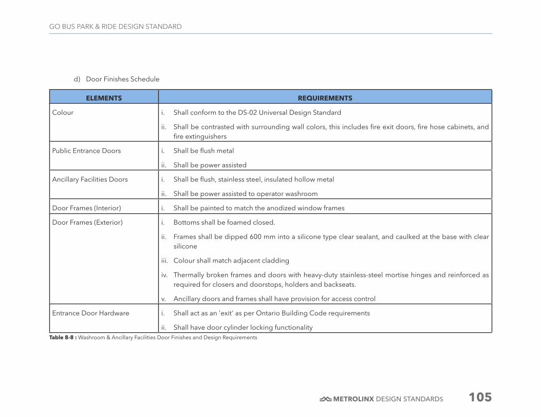
DESIGN STANDARDS 105
GO BUS PARK & RIDE DESIGN STANDARD
ELEMENTS REQUIREMENTS
Colour i. Shall conform to the DS-02 Universal Design Standard
ii. Shall be contrasted with surrounding wall colors, this includes fire exit doors, fire hose cabinets, and fire extinguishers
Public Entrance Doors i. Shall be flush metal
ii. Shall be power assisted
Ancillary Facilities Doors i. Shall be flush, stainless steel, insulated hollow metal
ii. Shall be power assisted to operator washroom
Door Frames (Interior) i. Shall be painted to match the anodized window frames
Door Frames (Exterior) i. Bottoms shall be foamed closed.
ii. Frames shall be dipped 600 mm into a silicone type clear sealant, and caulked at the base with clear silicone
iii. Colour shall match adjacent cladding
iv. Thermally broken frames and doors with heavy-duty stainless-steel mortise hinges and reinforced as required for closers and doorstops, holders and backseats.
v. Ancillary doors and frames shall have provision for access control
Entrance Door Hardware i. Shall act as an 'exit' as per Ontario Building Code requirements
ii. Shall have door cylinder locking functionality Table 8-8 : Washroom & Ancillary Facilities Door Finishes and Design Requirements
d) Door Finishes Schedule

DESIGN STANDARDS 106
GO BUS PARK & RIDE DESIGN STANDARD
Door Guards i. Power-assisted doors where they open into a barrier free route of travel shall be provided with cane- detectable guardrails or other barriers at right angles to the wall containing the door. To make it easy to locate the power door operator, the push bar shall be installed along the vertical surface at the end of the door guard
Controls for Power Assisted Doors
i. Shall conform to the DS-02 Universal Design Standard
ii. Controls for automatic doors shall consist of vertical push bars 914mm in height and 152mm in width, providing an activation area along the entire span of the vertical bar.
Bottom edge of controls for automatic doors shall be mounted 200mm max above the floor and located at least 600mm clear from the door in the open position.
iii. Controls for automatic doors shall be mounted at least 1000mm away from any adjacent inside corner and return wall
Hinges i. Shall not be piano type
ii. Exterior doors shall have restriction to opening beyond 90 degreesTable 8-8, Continued: Washroom & Ancillary Facilities Door Finishes and Design Requirements
ELEMENTS REQUIREMENTS
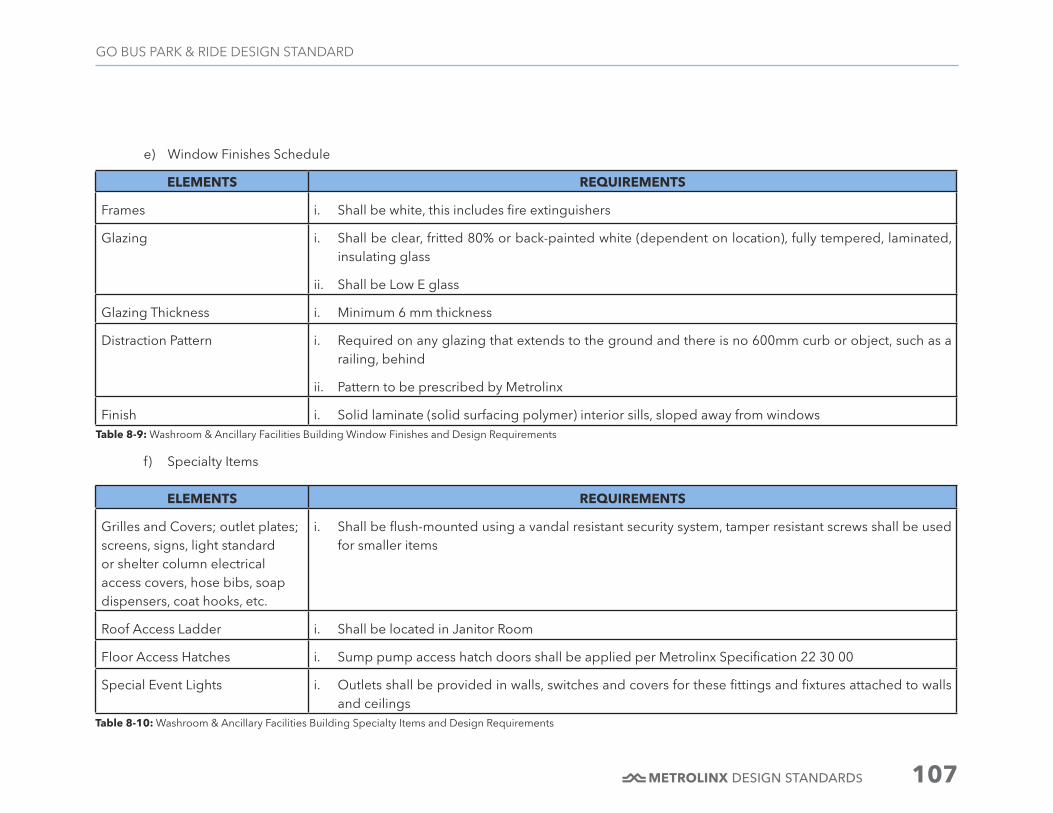
DESIGN STANDARDS 107
GO BUS PARK & RIDE DESIGN STANDARD
ELEMENTS REQUIREMENTS
Frames i. Shall be white, this includes fire extinguishers
Glazing i. Shall be clear, fritted 80% or back-painted white (dependent on location), fully tempered, laminated, insulating glass
ii. Shall be Low E glass
Glazing Thickness i. Minimum 6 mm thickness
Distraction Pattern i. Required on any glazing that extends to the ground and there is no 600mm curb or object, such as a railing, behind
ii. Pattern to be prescribed by Metrolinx
Finish i. Solid laminate (solid surfacing polymer) interior sills, sloped away from windows
f) Specialty Items
ELEMENTS REQUIREMENTS
Grilles and Covers; outlet plates; screens, signs, light standard or shelter column electrical access covers, hose bibs, soap dispensers, coat hooks, etc.
i. Shall be flush-mounted using a vandal resistant security system, tamper resistant screws shall be used for smaller items
Roof Access Ladder i. Shall be located in Janitor Room
Floor Access Hatches i. Sump pump access hatch doors shall be applied per Metrolinx Specification 22 30 00
Special Event Lights i. Outlets shall be provided in walls, switches and covers for these fittings and fixtures attached to walls and ceilings
Table 8-10: Washroom & Ancillary Facilities Building Specialty Items and Design Requirements
e) Window Finishes Schedule
Table 8-9: Washroom & Ancillary Facilities Building Window Finishes and Design Requirements

DESIGN STANDARDS 108
GO BUS PARK & RIDE DESIGN STANDARD
g) Exterior Finishes
Figure 8-3: Typical Washroom & Ancillary Facilities Elevation Diagram
REFER TO GO STATION ARCHITECTURAL DESIGN STANDARD DS-04 & WAYFINDING DESIGN STANDARD DS-03

DESIGN STANDARDS 109
GO BUS PARK & RIDE DESIGN STANDARD
ID NAME DESCRIPTION
Exterior Wall Systems
EW1 N/A N/A
EW2 Prefinished Aluminum Panel System 2
Prefinished aluminum panel, rain- screen assembly with concealed fasteners. Colour Pantone 2333 C
EW3 Prefinished Aluminum Louvre System 3
Prefinished aluminum architectural louvre. Colour Pantone 2333 C
EW4 Exterior Wall Base Sandblasted Architectural Precast Concrete.
Roofing
R1 Insulated Membrane Roofing System Insulated, low solar reflectance (SR) roofing.
Exterior Windows
W1 Exterior window - Vision Glass Thermally Broken Aluminium window system - Double-glazed units, Vision Glass Low E coating on the #3 Surface; anodised finish
W2 Exterior window - 80% Fritted Vision Glass
Same as W1 w/80% ceramic frit on #2 surface
W3 Exterior window - Fritted Glazed Spandrel Panel
Same as W1 w/80% ceramic frit on #2 surface, back painted white on #4 surface
Table 8-11: Washroom & Ancillary Facilities Exterior Finishes Schedule

DESIGN STANDARDS 110
GO BUS PARK & RIDE DESIGN STANDARD
h) Interior Finishes
Figure 8-4: Washroom & Ancillary Facilities Finish Floor Plan Diagram
*Refer to DRM for Technical Room(s) requirements

DESIGN STANDARDS 111
GO BUS PARK & RIDE DESIGN STANDARD
ID NAME DESCRIPTION
Floors
FF1 Floor Finish 1 Small format, non-slip porcelain tile. Colour: slate gray
FF2 Floor Finish 2 Sealed concrete
Walls
WF1 Wall Finish 1 Painted gypsum wall board-white
WF2 Wall Finish 2 Large format porcelain panel- max 2.5m x 1.2m x 3mm- Colour: Pantone Cool Grey 1CP
WF3 Wall Finish 3 Small format porcelain wall tile. Colour: Pantone P1-1 C
WB1 Wall Base 1 Porcelain tile wall base- Colour: slate grey
WB2 Wall Base 2 Epoxy cove base
Ceilings
CF1 Ceiling Finish 1 No ceiling – underside of structure painted white
CF2 Ceiling Finish 2 Painted gypsum wall board - white
CF3 Ceiling Finish 3 High Gloss Lacquered Panel (Exterior Grade Solid Surfacing for exterior conditions)- Colour: Pantone 2019 CP
Table 8-12: Washroom & Ancillary Facilities Interior Finishes Schedule

DESIGN STANDARDS 112
GO BUS PARK & RIDE DESIGN STANDARD
Figure 8-5: Washroom & Ancillary Facilities Ceiling Plan Diagram
*Refer to DRM for Technical Room(s) requirements
LE2
LE2

DESIGN STANDARDS 113
GO BUS PARK & RIDE DESIGN STANDARD
Table 8-13: Washroom & Ancillary Facilities Luminaire Types
LUMINAIRE LE-1
Location i. Washrooms (Public and Staff)
Requirements i. Provides general lighting to the Public Washrooms
ii. Recessed adjustable LED fixture
Product Description i. Adjustable round LED module integrated with a gray finish square trim
ii. Die cast aluminum optical assembly and frame with black steel housing
iii. Vacuum plated metallized PC reflector available in 29°
iv. Optical assembly adjustable 30° in all axes
v. Optical accessories options (Frosted lens/ Louver/Visor)
vi. Recessed fixture must be rated IP67
LUMINAIRE LE-2
Location i. Janitor Rooms
Requirements i. Hung from open ceiling/ structural members
ii. Light levels must have minimum 50 lux horizontal and 30 lux vertical.
Product Description i. LED linear fixture with reflectors
ii. LED system must be suitable for damp locations