DryVAC™ Vapor Recovery Systems - Symex...
22
DryVAC™ Vapor Recovery Systems HEADQUARTERS OFFICE SYMEX Americas, LLC 5397 West 86 th Street P.O. Box 681246 Indianapolis, IN 46268 Phone: 317-872-4321 Attention: Tim Hammond, Pres. Or The Tulsa Office SYMEX Americas, LLC 6840 East 112 th Street South Bixby, OK 74008-2062 Phone 918-231-9698 Attention: Bill Ball, VP E-Mail: [email protected]
-
Upload
vuongnguyet -
Category
Documents
-
view
267 -
download
7
Transcript of DryVAC™ Vapor Recovery Systems - Symex...
DryVAC™ Vapor Recovery Systems
HEADQUARTERS OFFICE SYMEX Americas, LLC
5397 West 86th Street P.O. Box 681246
Indianapolis, IN 46268 Phone: 317-872-4321
Attention: Tim Hammond, Pres.
Or The Tulsa Office
SYMEX Americas, LLC 6840 East 112th Street South
Bixby, OK 74008-2062 Phone 918-231-9698 Attention: Bill Ball, VP E-Mail: [email protected]
Page 3 ©2003 SYMEX Americas, LLC
DDDrryyy VVVRr RRUUU SSSyyysssttteeemmmsss
Vapour Recovery Units
VAPOR RECOVERY SYSTEMS
Adsorption on Activated Carbon
&
Regeneration by means of a DryVAC™ Vacuum Compressor
Page 4 ©2003 SYMEX Americas, LLC
The SYMEX Americas DryVAC™ VRS process consists of three major events:
1) Adsorption on activated carbon
2) Regeneration by means of vacuum
3) Re-absorption in a liquid (gasoline)
Page 5 ©2003 SYMEX Americas, LLC
Adsorption on Activated Carbon
The pore structure of activated carbon provides a fast internal surface of up to 1800 m2 per gram (7,231,624 ft2 per pound).
This surface is activated by steam or by phosphoric acid (H3PO4)
The internal surface has a huge affinity towards hydrocarbon molecules.
The “loading factor” for gasoline vapors is 35 to 50 % by weight.
Not all the hydrocarbons are regenerated by vacuum.
A significant quantity stays on the carbon and forms the so-called “heel”. The effective loading factor is called “working capacity” of the carbon.
The working capacity for gasoline vapors is 4 to 20 % by weight.
Gasoline vapor consists mainly of propane, butane, pentane, hexane, heptane and some aromatics.
(approximately 5, 40, 40, 10, 4 and 1 percent by volume respectively
All emission regulations can be achieved:
TA-Luft: 150 mg/m3
EU Directive: 35 g/m3
US EPA 5 mg/liter loaded
The natural emission value of activated carbon regenerated by vacuum is approximatley 0.1 to 2.0 g/m3 (0.0000075 pounds per cubic foot to 0.00015
pounds per cubic foot).
Page 6 ©2003 SYMEX Americas, LLC
Regeneration by Vacuum
The loading factor of an adsorption process depends on the partial pressure of the components and the temperature.
The adsorption of the hydrocarbons takes place at atmospheric pressure and temperature. The loading factor at low vacuum is much lower, providing the
energy necessary to release (desorb) hydrocarbons from the surface of the activated carbon.
A vacuum compressor transfers the released vapors to an atmospheric re-absorber column where they are returned to the liquid phase.
The adsorption of the hydrocarbons from carbon produces heat. The
temperature in the carbon bed will rise during adsorption and fall during regeneration.
Because of the relative huge mass of the carbon compared to the small mass of the adsorbed vapors to be desorbed, the actual carbon bed temperature will not
change significantly during proper operation. A temperature swing of approx. 5 to 15
oC (9°F to 27°F) is normal.
The most effective desorption pressure is between
30 to 130 millibars absolute (0.435 to 1.885 pounds/in2 absolute).
In the last phase of the regeneration a small amount of air is bled in over the activated carbon bed from the top. This air strips and displaces hydrocarbons
from the top layer of the activated carbon to ensure the desired emission level.
The hydrocarbon concentration of the hydrocarbon/air mixture leaving the activated carbon beds is 80 to 100 percent by volume. This means it is
relatively easy to recover the hydrocarbon vapor in a simple absorber column, operating at atmospheric pressure and ambient temperature.
Page 7 ©2003 SYMEX Americas, LLC
Types of Vacuum Systems
Vacuum can be generated in many different ways.
The most important factors for the selection of the vacuum system are safety, low energy consumption, and reliability.
Safety related risks are fire and explosion since the vapors may be in the
flammable range. The compressor selected should be explosion-shock proof
to a minimum of 10 bars (140 psig) and the internal process temperature should be less than 140
oC (284°F).
(Explosive gas Group IIA, T3)
Page 8 ©2003 SYMEX Americas, LLC
Liquid ring vacuum pumps
The first VRU manufacturers used liquid ring vacuum pumps. Due to the direct contact of the vapor with the internal liquid ring
inside the pump the temperature stays relatively low (40 to 70
oC, 104°F to 158°F)
The energy consumption is high (0.04 kWh/m3) (0.00113 kWh/ft3)
due to the friction losses in the liquid ring.
In most applications the liquid ring needs to be protected against frost when it is idle in the wintertime. Ethylene glycol or a 85/15 percent by weight
glycol/water mixture is used as seal fluid on the liquid ring. The fluid is injected into the pump and leaves the pump together with the desorbed vapors.
Gasoline and glycol do not mix and can be easily separated on basis of difference in specific gravity. The glycol is cooled in a heat exchanger during
its continuous circulation.
Glycol is sensitive to degradation by many factors such as emulsification of hydrocarbons by virtue of mutual solvents such as MTBE and TAME used as oxygenated, pH variance leading to severe corrosion when low, and foaming and carryover when high. The result is glycol losses and/or severe corrosion.
The major disadvantages of the wet vacuum system are:
a) High energy consumption
b) Glycol losses
c) Corrosion and abrasion
d) Secondary waste problem
e) Limited vacuum level
Page 9 ©2003 SYMEX Americas, LLC
DryVAC™ screw vacuum compressors
DryVAC™ Screw Vacuum Compressors have been used for several years. They have been proven so reliable and beneficial that many liquid ring
vacuum pumps have been replaced with DRYVac™ compressors. Even though the initial replacement cost is higher, the justifications for these
replacements are 1) lower operational costs, 2) no waste treatment costs, 3) much lower energy costs, 4) higher reliability, and 5) increased safety.
Oil injected compressors are less suitable for the application in VRS’s, since some of the desorbed products will condense inside the compressor, mix with
and emulsify with the lubrication oil.
The DryVAC™ Screw Vacuum Compressors use only half the energy of a liquid ring vacuum compressor, resulting in a much lower
compressor temperature (40°C to 50 oC, 104°F to 122°F).
The major advantages of the DryVAC™ Vacuum Vapor Recovery System are:
a) Low energy consumption
b) No glycol losses
c) No Corrosion problems
d) Low vacuum level possible (Wider field of application)
e) Highly reliable
f) Very simple system
g) Energy consumption proportional to mass of HC recovered
h) Lower gasoline circulation flow rate (smaller pumps with smaller motors using lower electrical energy)
Page 10 ©2003 SYMEX Americas, LLC
Re absorber column
The vapors recovered from the loading of tank trucks consist mainly of light end hydrocarbons (butane and pentane). The most effective recovery approach is to put them back into the product they originally came from. That product is
usually gasoline.
The vapors removed from the activated carbon during regeneration are highly concentrated.
By bringing them in direct contact with a counter flowing stream of gasoline in a re-absorber vessel, the hydrocarbon vapors leaving the vacuum compressor
are recovered and sent back to storage as recovered gasoline.
The air present inside the carbon beds, and the purge air pulled in during the final phase of the regeneration, saturates with hydrocarbons inside the re-
absorber. It is directed into the inlet vapor stream coming from the loading rack where it enters the on-stream adsorber vessel and is recovered.
This recycle flow is returned to the inlet of the system and passes through the
adsorber on line where the hydrocarbons are re-adsorbed.
Page 11 ©2003 SYMEX Americas, LLC
Gasoline circulation system
The recovered products desorbed from the activated carbon during regeneration are volatile hydrocarbons, which originate from gasoline. Since they leave the activated carbon at a high concentration, they can be easily recovered in a re-absorber via a counter flow of gasoline at ambient pressure and temperature.
The Reid Vapor Pressure (RVP) of the gasoline used for the recovery process will gradually increase. It is therefore recommended to use a product with a
predetermined daily exchange in the terminal, to prevent the product from going off spec. The gasoline day tank is the ideal source of the absorbent.
Two independent centrifugal pumps maintain the circulation of the gasoline.
The gasoline flows from the top down over a bed of contact rings inside the re-absorber column. It is collected in the bottom of the column.
The inlet flow to the top of the re-absorber usually has a fixed setting by means of an adjustable hand valve. The return flow is controlled in such a way that the liquid level in the bottom of the column is constant. This is accomplished by a
variable frequency drive on the motor of the return pump.
To prevent overfilling of the column, two independent and automatic shut-off alarm systems are included; the PLC, and a hard-wired safety loop which
interact with:
Motorised ball valves in the absorbents inlet and outlet line. Safety valves in the inlet and outlet lines. Automatic start of the return compressor at high level in the re-
absorber during stand-by of the VRS.
Page 12 ©2003 SYMEX Americas, LLC
Start-Stop Control of the VRS
The SYMEX Americas VRS only runs during actual truck loading. This means that a signal has to be derived from loading preparation activity at the truck rack
to signal that loading is about to start or stop. On modern truck terminals this signal is usually generated by the loading automation system.
Energy efficient operation
The rate and the hydrocarbon concentration of the vapors coming from any loading facility vary a great deal. The capacity of carbon beds and the vacuum pump is fixed. This implies that during low activity at the terminal, the VRS is oversized and the energy consumption related to the mass of product recovered
is high.
To offset this deficiency, the SYMEX Americas DryVAC™ VRS uses a dry screw vacuum compressor driven with a motor controlled by a variable frequency controller. This means that the energy consumption of the compressor is directly proportional to its speed, which his controlled
proportionally to the loading rate and hydrocarbon concentration.
It seems logical that the vacuum level at the end of the regeneration cycle depends on the mass of hydrocarbons to be removed. If the load on the carbon
bed is low, the required end vacuum level will sooner be achieved. The vacuum level in the carbon beds is measured by means of an electronic pressure
transmitter. The speed of the vacuum compressor is thereby reduced, resulting in even lower energy consumption.
This way the energy consumption is proportional to the mass of
hydrocarbons to be recovered.
Page 13 ©2003 SYMEX Americas, LLC
Safety Aspects of the DryVAC™ VRS
The DryVAC™ Screw Vapor Recover Unit is considered to be the most safe and reliable system available on the market today.
Due to the special design of the Vacuum Compressor the thermodynamic energy required for compressing is reduced to an absolute minimum, resulting
in very low compressor temperatures. Liquid ring compressors rely on the injection of liquid to achieve the same level of safe compression temperatures.
The very solid construction of the DryVAC™ compressor does not present any risk of breakdown of fragile blades, spark potentials, cavitation corrosion, or corrosion, plugging, or fouling of the glycol circulation system as occurs in
systems with liquid ring pumps..
The DryVAC™ compressor can easily be speed controlled to adapt the compression capacity to the variable vapor inlet conditions. This minimises the
risk of carbon bed overheats to nearly zero.
The safety and reliability of the DryVAC™ System is recognized by the world’s major Chemical and Petrochemical industries and storage companies
such as:
DOW Chemicals, Oiltanking, BP Oil, SHELL, TOTAL FINA ELF, REPSOL, EKO etc.
Page 14 ©2003 SYMEX Americas, LLC
Design Basis for a VRS
The following data are required for a proper design of a VRS.
The Peak Throughput
The peak (maximum instantaneous) throughput is required information. It is needed to calculate the pressure drop over the entire vapor collection system
including the VRS. In principle the pressure available at the vapor connection of the truck should be sufficient to transport the vapors through the vapor arm,
the flame arrestors, the vapor collection pipeline and the VRS.
The peak throughput depends on the number of loading arms connected simultaneously at all loading spots.
For a two spot terminal this can be eight arms. For a ten spot terminal this is usually not more than twenty arms.
The actual number is specific to each terminal and should be agreed upon with the terminal operator.
SYMEX Americas provides basic engineering and pressure drop calculations as
a standard part of the supply of the VRS.
Page 15 ©2003 SYMEX Americas, LLC
b) The throughput per cycle
The cycle time of the VRS is usually equal to the truck turn around time (15 minutes).
The amount of vapor generated by the loading of trucks per cycle is equal to the
sum of the truck capacities loaded simultaneously.
If the average truck capacity is 35 m3 (9,245 gallons) and the number of loading spots is four,
the maximum vapor throughput per cycle is 4x 35 = 140 m3 (36,984 gallons or 4,944 cubic feet).
This value is one of the parameters to determine the size of activated carbon
beds.
Page 16 ©2003 SYMEX Americas, LLC
c) The four-hour throughput period
The intensity of loading is not a constant in any terminal. Usually there is peak activity in the morning and in the afternoon.
The activated carbon beds act as buffers. They store peak volumes of hydrocarbons during high loading rate periods, and give up the stored
hydrocarbons during regeneration in low loading rate periods. This is why the size of the vacuum system is based on an extended period of
time rather than one averaged loading cycle.
If terminal activity is relatively low in the afternoon, the vacuum system creates a buffer for the next expected peak loading cycle.
In order to size a VRS vacuum system the daily/weekly throughput profile is required over the total period that the terminal is open.
If the loading profile of a terminal is not available, SYMEX Americas can assist
in determining the actual a profile. This is done by observation, and requires the full cooperation of the client.
Page 17 ©2003 SYMEX Americas, LLC
d) The vapor concentration
The vapor concentration depends strongly on whether or not vapor balancing is actually taking place as the tank truck off-loads its product. This is mandated
by the US EPA, the Clean Air Act, and Phase 2 of the EU Directive.
This means the vapor circuit including the recovery of the vapors at the service station is completely closed. The concentration of the vapor above the gasoline
liquid level of the in-ground storage tank at the service station will be approximately 40 percent by volume.
The vapor space above diesel storage tanks contains almost no hydrocarbons.
In the case of mixed loading, where gasoline and diesel are laoded simultaneously, the hydrocarbon concentration of the vapors leaving the loading
rack will be less.
Page 18 ©2003 SYMEX Americas, LLC
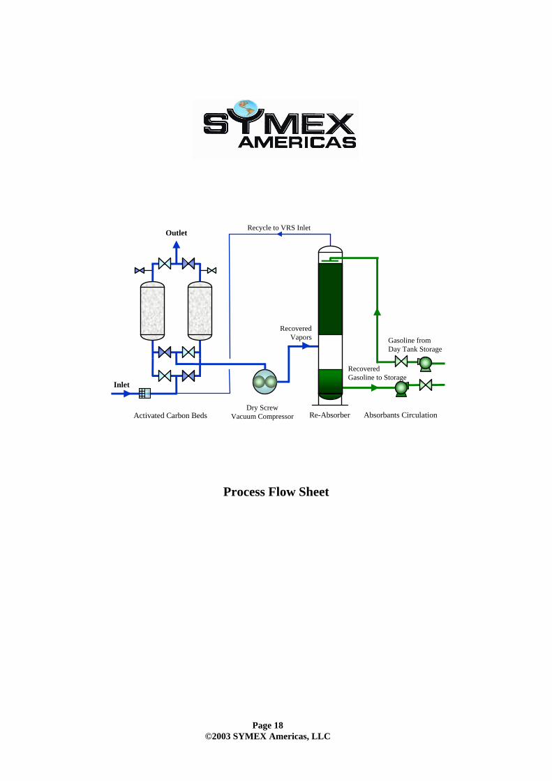
Re-Absorber Absorbants CirculationDry ScrewVacuum Pumps
Inlet
Activated Carbon Bed
Outlet
Dry Screw Vacuum Compressor
Process Flow Sheet
Recycle to VRS Inlet
Recovered Vapors
Recovered Gasoline to Storage
Gasoline from Day Tank Storage
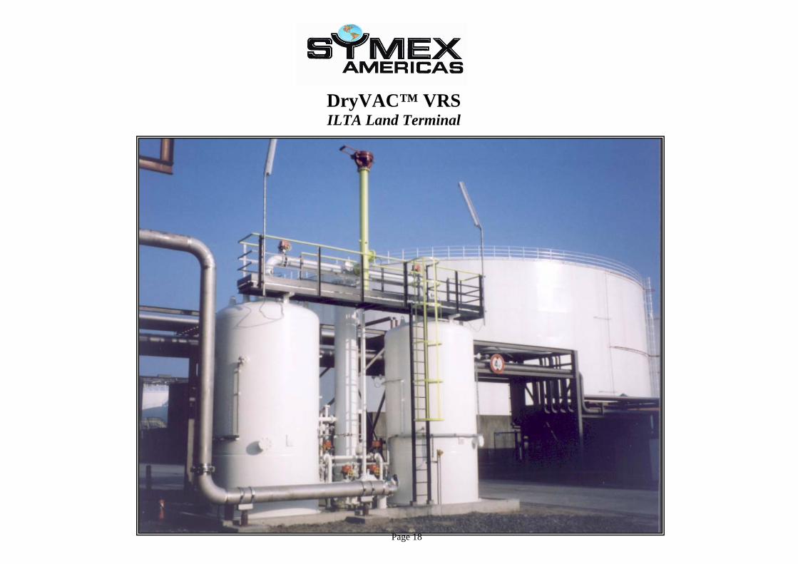
DryVAC™ VRS ILTA Land Terminal
Page 18
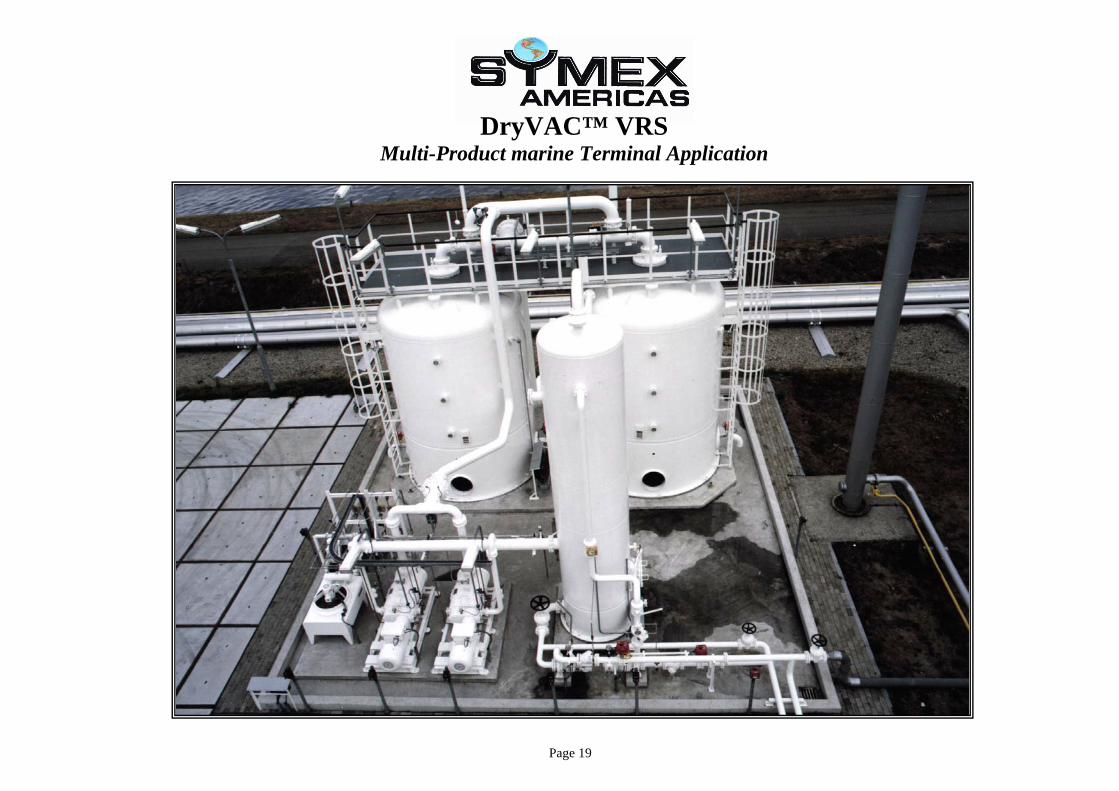
DryVAC™ VRS Multi-Product marine Terminal Application
Page 19
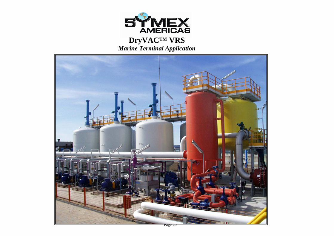
DryVAC™ VRS Marine Terminal Application
Page 20
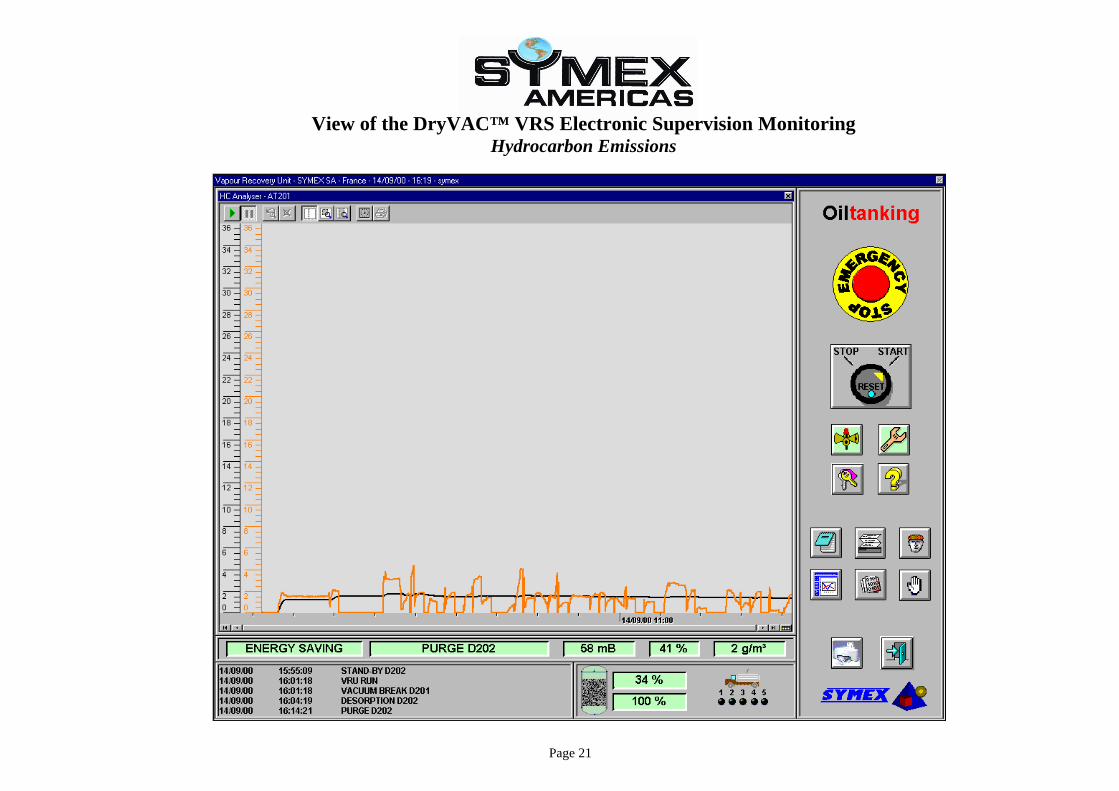
View of the DryVAC™ VRS Electronic Supervision Monitoring Hydrocarbon Emissions
Page 21
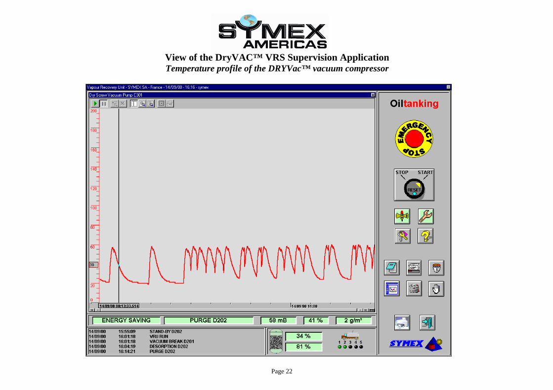
View of the DryVAC™ VRS Supervision Application Temperature profile of the DRYVac™ vacuum compressor
Page 22