DRYVAC 50 & 100 S - PolVac Corp · DRYVAC 50/100 S Manual ... The gas enters the pump through the...
32
Français DRYVAC 50 & 100 S GA 01.413/1.02
Transcript of DRYVAC 50 & 100 S - PolVac Corp · DRYVAC 50/100 S Manual ... The gas enters the pump through the...

Fran
çais
DRYVAC 50 & 100 SGA 01.413/1.02

2
DRYVAC 50/100 S Manual
Contents Page
Safety Information ...................................................... 2
1 Description ............................................................ 41.1 Design and Function ......................................... 41.2 Standard Equipment ......................................... 61.3 Technical Data .................................................. 81.4 Ordering Data ................................................... 9
2 Installation ........................................................... 102.1 Adapting the Pump to the Process .................. 102.2 Setting up the Pump ....................................... 102.3 Electrical Connections .................................... 11
2.3.1 Setting the Pump to theOperating Voltage .................................. 12
2.3.2 Connecting an ExternalRemote Control ..................................... 13
2.4 Connecting the Cooling Water ........................ 152.5 Connecting the Inert Gas and
Compressed Air Supply .................................. 152.6 Setting the Pump to Match the Process ..........162.7 Checking the Direction of Rotation .................172.8 Connecting the Intake and Exhaust Lines .......18
2.8.1 Connecting the Intake Line ................... 182.8.2 Connecting the Exhaust Line .................18
2.9 Options (Standby, Flush, LTO, & Battery) .......182.9.1 Standby Option ..................................... 182.9.2 Flush Valve Option ................................. 202.9.3 LTO Option ............................................ 212.9.4 Battery Backup Option .......................... 21
3 Operation ............................................................. 223.1 Start-up ........................................................... 223.2 Pumping Non-Aggressive Gases ..................... 233.3 Shutdown ........................................................ 233.4 Response to Malfunctions ............................... 23
3.4.1 Process Temperature Fault ................... 233.4.2 Warnings .............................................. 243.4.3 Alarms ................................................... 243.4.4 Oil Pressure Warning and Alarm ..........24
3.5 Shutdown for an Extended Period .................. 253.6 Storing and Shipping ...................................... 253.7 Report (REPORT button) ................................. 26
4 Maintenance......................................................... 284.1 Routine Maintenance ...................................... 284.2 Replacing the Exhaust Silencer ...................... 28
5 Troubleshooting .................................................. 29
Note:
References to illustrations consist of (figure number/itemnumber). For example, (1/2) refers to Figure 1, Item 2.
Safety InformationHazard analyses per European standard EN 1012 wereconducted for the DR YVAC 50 and 100 S pumps. Everyperson involved with connecting, operating or maintain-ing these pumps shall have read and understood thisDRYVAC operating instruction manual in order to avoidhazards and operating malfunctions.
DRYVAC pumps are designed to pump down vacuumchambers to pressure values in the rough and finevacuum ranges, and are intended for industrial use.
Precautionary notes in these instructions:Warning – This indicates procedures and operationswhich must be strictly observed to prevent hazards topersons.
Caution – This indicates procedures and operationswhich must be strictly observed to prevent damage ordestruction of the pump.
Media compatibilityDRYVAC pumps are authorized for use only in those ap-plications and processes which are listed in the descrip-tion section of this instruction manual. Contact Leyboldbefore using a DR YVAC for applications and processeswhich are not listed.
Warning Standard DRYVAC pumps are notsuited for pumping media whichcould ignite or explode. If thesepumps are nonetheless used in suchapplications, the owner / operatormust take the precautionary mea-sures required for explosion protec-tion in compliance with legalrequirements.
Electrical Safety
Warning Disconnect the pump from the mainpower supply before beginning anyassembly or disassembly work. Takemeasures to ensure that the pumpcannot be started. The electrical con-nections shall be made only by aqualified and licensed electrician, inaccordance with VDE standard 0105and as per the VDE 0100 guidelinesand local codes.
3
DRYVAC 50/100 S Manual
Mechanical Safety
Warning Do not expose any parts of the body tothe vacuum. In particular do not oper-ate the pump with flanges open, orloosen any flange, oil filling or drainscrews when a vacuum is present,even if the pump is switched off.
Remove the cover panels only when the pump isswitched of f.
Do not remove the pump or perform any maintenancework before it has been vented and has come to a com-plete stop.
Protection Against Hazardous GasesThe exhaust line connections must be tight. Hazardousgases could escape at leaks or the gases being pumpedcould react with humid air .
The pump’ s overall leak rate is <1·10 -5 mbar·l·s -1. Installa housing evacuation unit when pumping hazardousgases.
Whenever the pump is opened to:• refit the purge-control plate• check the direction of rotation• remove the intake or exhaust line• remove the pump from the system
the following safety instructions must be observed:
WarningIf the DRYVAC has pumped hazard-ous gases, you must determine thenature of the hazard and take the ap-propriate safety precautions. Complywith all safety regulations. Take ad-equate safety precautions beforeopening the intake or exhaust.
If necessary, use gloves, a respiratorand/or protective clothing and workunder an exhaust hood.
DRYVACs that are used in semiconductor processes, forexample, can be contaminated with process gases. Thesegases may be toxic and hazardous to health. In addition,deposits with similarly dangerous properties can form in-side the pump. Many of these gases and deposits canseriously corrode the pump, especially when they aremixed with humid air .
To avoid health hazards and corrosion damage when thepump is detached from the system, lay a container ofdesiccant on the inlet splinter guard and then seal thepump immediately at all flange connections. Store thepump with a desiccant, in a polyethylene bag.
Handling PFPESince PFPE is used when pumping corrosive media, itcan be contaminated with these media during use. Thusit is necessary to take appropriate precautionary mea-sures depending on the medium that has been pumped(see “Protection against hazardous gases”).
WarningHazardous decomposition productsmay be formed at temperatures ex-ceeding 350°C (660°F). Thus smok-ing is prohibited in rooms wherePFPE is being used or handled; donot expose cigarettes or other to-bacco products to PFPE.
All safety regulations applicable to handling the mediumbeing pumped shall also be observed when working withPFPE and the pump.
PFPE must be reclaimed or disposed of as a toxicwaste.
Returning EquipmentComplete the form at the back of this manual before re-turning equipment to Leybold for service. This form noti-fies us of any toxic or other harmful products (as definedby the applicable regulations such as the Common Mar-ket Guideline L360, 1976/1979 or VBG 16) that may ex-ist in or near the equipment. Attach the form to the pumpor enclose it with the pump. This statement detailing thecontamination is required to satisfy legal requirementsand to protect our employees.
4
DRYVAC 50/100 S ManualSection 1 — Description
1 Description
1.1 Design and FunctionThe DRYVAC 50S and 100S are dry-compressionvacuum pumps designed especially for semiconductoretching and CVD processes.
Each of these DR YVACs are four-stage hook-and-clawvacuum pumps.
Although both DR YVAC pumps are similar in design andoperation, there are differences, and these differencesare detailed in Section 1.3 Technical Data.
Pump operating principle
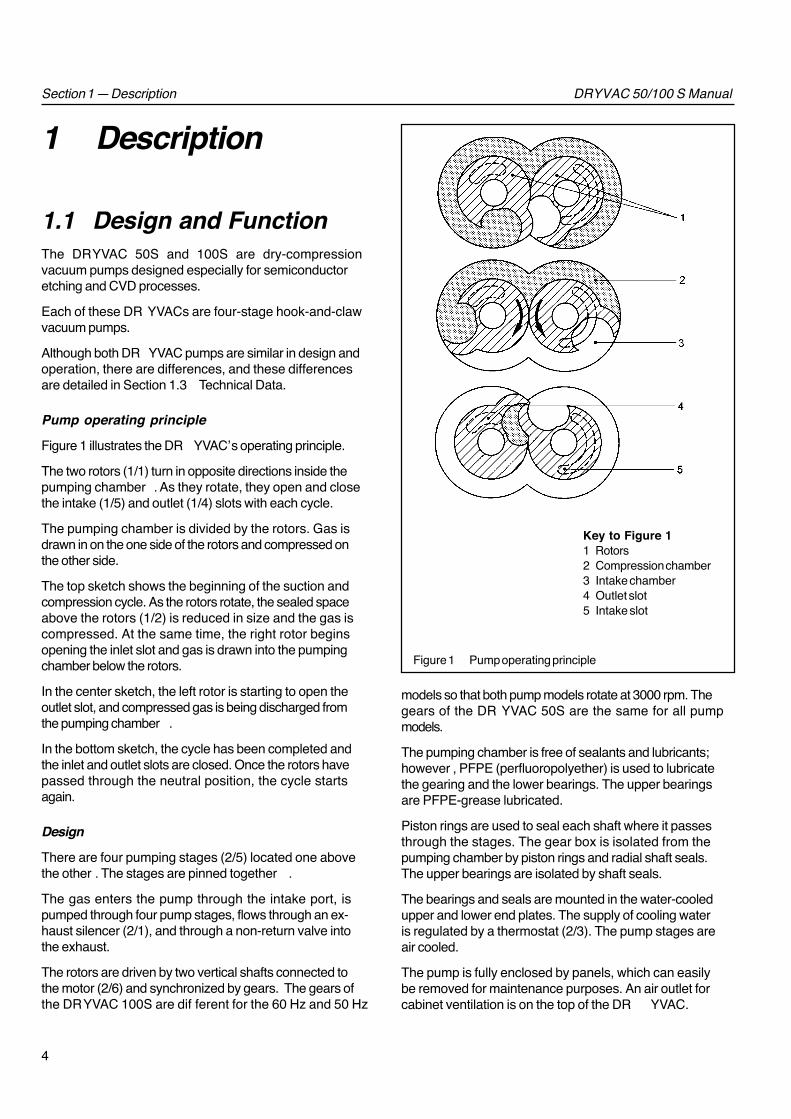
Figure 1 illustrates the DR YVAC’s operating principle.
The two rotors (1/1) turn in opposite directions inside thepumping chamber . As they rotate, they open and closethe intake (1/5) and outlet (1/4) slots with each cycle.
The pumping chamber is divided by the rotors. Gas isdrawn in on the one side of the rotors and compressed onthe other side.
The top sketch shows the beginning of the suction andcompression cycle. As the rotors rotate, the sealed spaceabove the rotors (1/2) is reduced in size and the gas iscompressed. At the same time, the right rotor beginsopening the inlet slot and gas is drawn into the pumpingchamber below the rotors.
In the center sketch, the left rotor is starting to open theoutlet slot, and compressed gas is being discharged fromthe pumping chamber .
In the bottom sketch, the cycle has been completed andthe inlet and outlet slots are closed. Once the rotors havepassed through the neutral position, the cycle startsagain.
Design
There are four pumping stages (2/5) located one abovethe other . The stages are pinned together .
The gas enters the pump through the intake port, ispumped through four pump stages, flows through an ex-haust silencer (2/1), and through a non-return valve intothe exhaust.
The rotors are driven by two vertical shafts connected tothe motor (2/6) and synchronized by gears. The gears ofthe DRYVAC 100S are dif ferent for the 60 Hz and 50 Hz
models so that both pump models rotate at 3000 rpm. Thegears of the DR YVAC 50S are the same for all pumpmodels.
The pumping chamber is free of sealants and lubricants;however , PFPE (perfluoropolyether) is used to lubricatethe gearing and the lower bearings. The upper bearingsare PFPE-grease lubricated.
Piston rings are used to seal each shaft where it passesthrough the stages. The gear box is isolated from thepumping chamber by piston rings and radial shaft seals.The upper bearings are isolated by shaft seals.
The bearings and seals are mounted in the water-cooledupper and lower end plates. The supply of cooling wateris regulated by a thermostat (2/3). The pump stages areair cooled.
The pump is fully enclosed by panels, which can easilybe removed for maintenance purposes. An air outlet forcabinet ventilation is on the top of the DR YVAC.
Figure 1 Pump operating principle
Key to Figure 11 Rotors2 Compression chamber3 Intake chamber4 Outlet slot5 Intake slot

5
DRYVAC 50/100 S ManualSection 1 — Description
Key to Figure 21 Exhaust silencer 5 Pump stages2 Pressure regulator 6 Motor3 Thermostat valve 7 Control unit4 Shutoff valve for the exhaust 8 Cooling water drain port (50S only)
Figure 2 Sectional drawing of a DRYVAC 50S (the 100S model is similar)
Exhaust shutoff valve
The exhaust valve (2/4) closes the exhaust when the pumpis not running. It operates on compressed air and is con-trolled by a solenoid valve. The valve’s position indicatorssignal whether the valve is open or closed.
Inert Gas Barrier and Purge Gas Device
The DRYVAC has a mechanism for barrier gas and forpurge gas.
Inert gas for these devices is connected at the back of thepump. It flows into the pump through the main inert gasvalve and two pressure regulators.
The barrier gas protects the lower radial shaft seals andbearings against aggressive media and particles. In addi-tion, the barrier gas is pumped to the exhaust pressureswitches and protects them against contamination.
The purge gas flows through the interstage purge block,the purge control plate, connecting pipes and nozzles,and into the three lower pump stages.
Electrical Equipment
The DRYVAC is monitored by several limit switches and aPT100 temperature sensor (refer to Table 1).
The temperature sensor measures the outlet temperatureof the cooling water . The pump monitors the process’ set-ting with this sensor and with the purge-gas flow indicator .
The signals of all monitoring equipment are brought to-gether in the control unit (2/7) where they are processed.
The control unit includes pushbutton controls and athree-line display which shows the DR YVAC’s operatingstatus in clear text; you have the option of English orGerman.

6
DRYVAC 50/100 S ManualSection 1 — Description
Figure 3 Simplified schematic of the DRYVAC pump
The control unit is mounted on the DR YVAC. It can also be at-tached up to 2.5 meters (8 feet) away . Its front panel fitsinto one half of a standard 19" rack (3 height modules).
During the initial start-up, you must set the DR YVAC tothe desired process. Thereafter , it can be switched onand of f with the ST ART and STOP buttons. Run-up, op-eration, and run-down are then automatically controlledas appropriate for the relevant process.
When unacceptable conditions arise, the DR YVAC auto-matically switches of f. The error messages are stored tosimplify troubleshooting.
The DRYVAC’s parallel interface allows you to connectthe pump to a central control system (see Figure 8).
The DRYVAC’s transformer and rectifier generate theDC voltages required for control and operation. Eachcontrol voltage has a separate fuse.
The DRYVAC also features a lockable main switch.
1.2 Standard EquipmentThe DRYVAC is delivered ready for operation with itsgear box filled with PFPE (perfluoropolyether) lubricant.
A sealing disk with dirt trap and a union flange are at-tached to the intake port.
The intake and exhaust ports and the inert gas fitting aresealed for shipping.
The pump is shipped with the following:• 2-meter (6.5-foot) main power cable without plug• Extension cable for the control unit• Allen key for removing or installing the exhaust
silencer
7
DRYVAC 50/100 S ManualSection 1 — Description
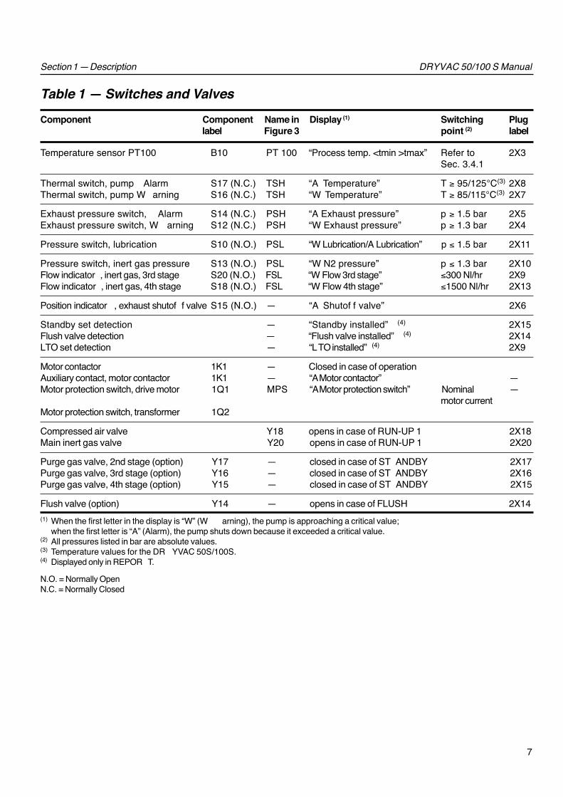
Table 1 — Switches and ValvesComponent Component Name in Display (1) Switching Plug
label Figure 3 point (2) label
Temperature sensor PT100 B10 PT 100 “Process temp. <tmin >tmax” Refer to 2X3Sec. 3.4.1
Thermal switch, pump Alarm S17 (N.C.) TSH “A Temperature” T ≥ 95/125°C(3) 2X8Thermal switch, pump W arning S16 (N.C.) TSH “W Temperature” T ≥ 85/115°C(3) 2X7
Exhaust pressure switch, Alarm S14 (N.C.) PSH “A Exhaust pressure” p ≥ 1.5 bar 2X5Exhaust pressure switch, W arning S12 (N.C.) PSH “W Exhaust pressure” p ≥ 1.3 bar 2X4
Pressure switch, lubrication S10 (N.O.) PSL “W Lubrication/A Lubrication” p ≤ 1.5 bar 2X11
Pressure switch, inert gas pressure S13 (N.O.) PSL “W N2 pressure” p ≤ 1.3 bar 2X10Flow indicator , inert gas, 3rd stage S20 (N.O.) FSL “W Flow 3rd stage” ≤300 Nl/hr 2X9Flow indicator , inert gas, 4th stage S18 (N.O.) FSL “W Flow 4th stage” ≤1500 Nl/hr 2X13
Position indicator , exhaust shutof f valve S15 (N.O.) — “A Shutof f valve” 2X6
Standby set detection — “Standby installed” (4) 2X15Flush valve detection — “Flush valve installed” (4) 2X14LTO set detection — “LTO installed” (4) 2X9
Motor contactor 1K1 — Closed in case of operationAuxiliary contact, motor contactor 1K1 — “A Motor contactor” —Motor protection switch, drive motor 1Q1 MPS “A Motor protection switch” Nominal —
motor currentMotor protection switch, transformer 1Q2
Compressed air valve Y18 opens in case of RUN-UP 1 2X18Main inert gas valve Y20 opens in case of RUN-UP 1 2X20
Purge gas valve, 2nd stage (option) Y17 — closed in case of ST ANDBY 2X17Purge gas valve, 3rd stage (option) Y16 — closed in case of ST ANDBY 2X16Purge gas valve, 4th stage (option) Y15 — closed in case of ST ANDBY 2X15
Flush valve (option) Y14 — opens in case of FLUSH 2X14(1) When the first letter in the display is “W” (W arning), the pump is approaching a critical value;
when the first letter is “A” (Alarm), the pump shuts down because it exceeded a critical value.(2) All pressures listed in bar are absolute values.(3) Temperature values for the DR YVAC 50S/100S.(4) Displayed only in REPOR T.
N.O. = Normally OpenN.C. = Normally Closed

8
DRYVAC 50/100 S ManualSection 1 — Description
1.3 Technical DataDRYVAC Model 50S
Pumping Speed:60 Hz operation ........................ 55 m3 · h-1 (32 cfm)50 Hz operation ........................ 45 m3 · h-1 (26 cfm)
Ultimate pressure:60 Hz operation .... ≤2.5 · 10-2 mbar (1.9 x 10⁻² Torr)50 Hz operation .......... ≤4 · 10-2 mbar (3 x 10⁻² Torr)
Maximum intake pressurein continuous operation* .......... 500 mbar (375 Torr)
Motor power ................................................. 3 kW (4 hp)
Rotational speed:60 Hz operation ........................................ 3600 rpm50 Hz operation ........................................ 3000 rpm
Noise level with the exhaust line connected .... 64 dB(A)
Cooling water requirements, approx:At water temp. of 15 °C (59°F) .. 70 l · hr -1 (18 gal/hr)Maximum cooling water temp. ............. 25°C (77°F)Cooling water pressure* ..... 2–10 bar (14–130 psig)Cooling water connection, female threads NPT 1/2"
Inert gas pressure* .................... 4–10 bar (43–130 psig)Inert gas connection, female thread ..................NPT 3/8"Inert gas consumption ........................... Refer to Table 2
Barrier gas pressure* ............................. 1.5 bar (7 psig)Purge gas pressure* ............................. 3.0 bar (29 psig)
Air pressure for activatingexhaust shutoff valve ............. 6–7 bar (72–87 psig)
Compressed-air connection, female thread .NPT 1/4"
Lubricant quantity gear box .......................... 0.8 l (0.8 qt)Maximum ambient temp. .......................... 40°C (104°F)Weight .....................................................190 kg (419 lb)
Intake port ..................................................DN 63 ISO-KExhaust port .................................................... DN 25 KF
*All pressures given in bar or mbar are absolute values.
DRYVAC Model 100S
Pumping Speed:60 Hz operation ........................ 100 m3 · h-1 (59 cfm)50 Hz operation ........................ 100 m3 · h-1 (59 cfm)
Ultimate pressure:60 Hz operation ......≤1.5 · 10-2 mbar (1.1 x 10⁻² Torr)50 Hz operation ......≤1.5 · 10-2 mbar (1.1 x 10⁻² Torr)
Maximum intake pressurein continuous operation* .......... 150 mbar (112 Torr)
Motor power ............................................ 4.0 kW (5.4 hp)
Rotational speed:60 Hz operation ........................................ 3000 rpm50 Hz operation ........................................ 3000 rpm
Noise level with the exhaust line connected .... 68 dB(A)
Cooling water requirements, approx:At water temp. of 15 °C (59°F) ... 100 l · hr -1 (26 gal/hr)Maximum cooling water temp. ............. 25°C (77°F)Cooling water pressure* ..... 2–10 bar (14–130 psig)Cooling water connection, female threads NPT 1/2"
Inert gas pressure* .................... 4–10 bar (43–130 psig)Inert gas connection, female thread ..................NPT 3/8"Inert gas consumption ........................... Refer to Table 2
Barrier gas pressure* ............................. 1.5 bar (7 psig)Purge gas pressure* ............................. 3.0 bar (29 psig)
Air pressure for activatingexhaust shutoff valve ............. 6–7 bar (72–87 psig)
Compressed air connection, female thread .NPT 1/4"
Lubricant quantity gear box .......................... 0.8 l (0.8 qt)Maximum ambient temp. ............................ 40°C (104°F)Weight ..................................................... 220 kg (485 lb)
Intake port ..................................................DN 63 ISO-KExhaust port .................................................... DN 25 KF
9
DRYVAC 50/100 S ManualSection 1 — Description
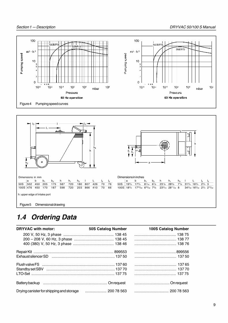
Figure 4 Pumping speed curves
Dimensions in mma b b1 b2 h h1 h2 I I1 I2 I3
50S 502 450 205 175 587 720 180 807 426 70 76100S 476 450 170 187 598 720 203 866 410 70 66
Dimensions in inchesa b b1 b2 h h1 h2 I I1 I2 I3
50S 193/4 173/4 81/16 67/8 231/8 283/8 71/8 313/4 163/4 23/4 3100S 183/4 1723/32 623/32 73/8 239/16 2811/32 8 343/32 165/32 23/4 219/32
h: upper edge of intake port
Figure 5 Dimensional drawing
1.4 Ordering DataDRYVAC with motor: 50S Catalog Number 100S Catalog Number
200 V, 50 Hz, 3 phase ............................................... 138 45 ....................................... 138 75200 – 208 V, 60 Hz, 3 phase ..................................... 138 45 ....................................... 138 77400 (380) V, 50 Hz, 3 phase ...................................... 138 46 ....................................... 138 76
Repair Kit ........................................................................... 899553 .......................................899556Exhaust silencer SD ........................................................... 137 50 ....................................... 137 50
Flush valve FS .................................................................... 137 60 ....................................... 137 65Standby set SBV ................................................................ 137 70 ....................................... 137 70LTO-Set .............................................................................. 137 75 ....................................... 137 75
Battery backup ............................................................ On request ................................. On request
Drying canister for shipping and storage .................... 200 78 563 ................................ 200 78 563
1 0
DRYVAC 50/100 S ManualSection 2 — Installation
2 Installation
2.1 Adapting the Pumpto the Process
Warning If the DRYVAC has pumped hazardousgases, you must determine the natureof the hazard and take the appropri-ate safety precautions. Comply withall safety regulations. Take adequatesafety precautions before opening theintake or exhaust.
The DRYVAC is delivered set up for the processes ofgroup B in Table 2 – unless specified otherwise by thesales order . This setup opens the purge-gas supply to theindividual pump stages.
If your process is in the “C” group in Table 2, installthe LTO set as described in Section 2.9.3.
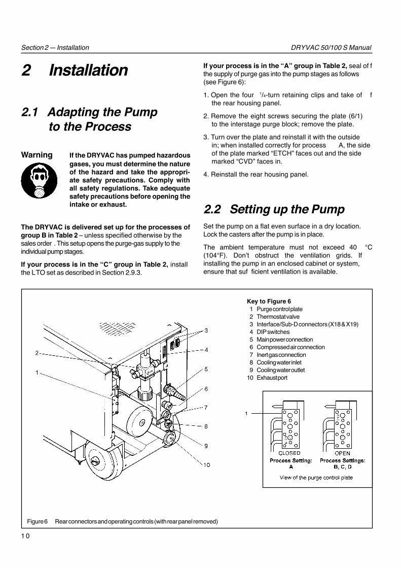
If your process is in the “A” group in Table 2, seal of fthe supply of purge gas into the pump stages as follows(see Figure 6):
1. Open the four 1/4-turn retaining clips and take of fthe rear housing panel.
2. Remove the eight screws securing the plate (6/1)to the interstage purge block; remove the plate.
3. Turn over the plate and reinstall it with the outsidein; when installed correctly for process A, the sideof the plate marked “ETCH” faces out and the sidemarked “CVD” faces in.
4. Reinstall the rear housing panel.
2.2 Setting up the PumpSet the pump on a flat even surface in a dry location.Lock the casters after the pump is in place.
The ambient temperature must not exceed 40 °C(104°F). Don’t obstruct the ventilation grids. Ifinstalling the pump in an enclosed cabinet or system,ensure that suf ficient ventilation is available.
Figure 6 Rear connectors and operating controls (with rear panel removed)
Key to Figure 61 Purge control plate2 Thermostat valve3 Interface/Sub-D connectors (X18 & X19)4 DIP switches5 Main power connection6 Compressed air connection7 Inert gas connection8 Cooling water inlet9 Cooling water outlet
10 Exhaust port
1 1
DRYVAC 50/100 S Manual
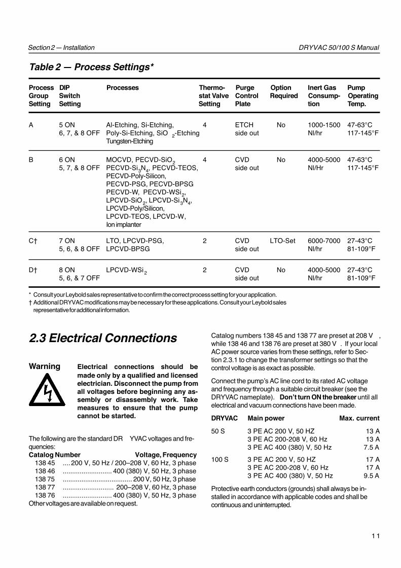
Table 2 — Process Settings*
Process DIP Processes Thermo- Purge Option Inert Gas PumpGroup Switch stat Valve Control Required Consump- OperatingSetting Setting Setting Plate tion Temp.
A 5 ON Al-Etching, Si-Etching, 4 ETCH No 1000-1500 47-63°C6, 7, & 8 OFF Poly-Si-Etching, SiO 2-Etching side out Nl/hr 117-145°F
Tungsten-Etching
B 6 ON MOCVD, PECVD-SiO2 4 CVD No 4000-5000 47-63°C5, 7, & 8 OFF PECVD-Si3N4, PECVD-TEOS, side out Nl/Hr 117-145°F
PECVD-Poly-Silicon,PECVD-PSG, PECVD-BPSGPECVD-W, PECVD-WSi2,LPCVD-SiO2, LPCVD-Si3N4,LPCVD-Poly/Silicon,LPCVD-TEOS, LPCVD-W,Ion implanter
C† 7 ON LTO, LPCVD-PSG, 2 CVD LTO-Set 6000-7000 27-43°C5, 6, & 8 OFF LPCVD-BPSG side out Nl/hr 81-109°F
D† 8 ON LPCVD-WSi2 2 CVD No 4000-5000 27-43°C5, 6, & 7 OFF side out Nl/hr 81-109°F
Section 2 — Installation
* Consult your Leybold sales representative to confirm the correct process setting for your application.† Additional DRYVAC modifications may be necessary for these applications. Consult your Leybold sales
representative for additional information.
2.3 Electrical Connections
Warning Electrical connections should bemade only by a qualified and licensedelectrician. Disconnect the pump fromall voltages before beginning any as-sembly or disassembly work. Takemeasures to ensure that the pumpcannot be started.
The following are the standard DR YVAC voltages and fre-quencies:Catalog Number Voltage, Frequency
138 45 ....200 V, 50 Hz / 200–208 V, 60 Hz, 3 phase138 46 .......................... 400 (380) V, 50 Hz, 3 phase138 75 ..................................... 200 V, 50 Hz, 3 phase138 77 ........................... 200–208 V, 60 Hz, 3 phase138 76 .......................... 400 (380) V, 50 Hz, 3 phase
Other voltages are available on request.
Catalog numbers 138 45 and 138 77 are preset at 208 V ,while 138 46 and 138 76 are preset at 380 V . If your localAC power source varies from these settings, refer to Sec-tion 2.3.1 to change the transformer settings so that thecontrol voltage is as exact as possible.
Connect the pump’s AC line cord to its rated AC voltageand frequency through a suitable circuit breaker (see theDRYVAC nameplate). Don’t turn ON the breaker until allelectrical and vacuum connections have been made.
DRYVAC Main power Max. current
50 S 3 PE AC 200 V, 50 HZ 13 A3 PE AC 200-208 V, 60 Hz 13 A3 PE AC 400 (380) V, 50 Hz 7.5 A
100 S 3 PE AC 200 V, 50 HZ 17 A3 PE AC 200-208 V, 60 Hz 17 A3 PE AC 400 (380) V, 50 Hz 9.5 A
Protective earth conductors (grounds) shall always be in-stalled in accordance with applicable codes and shall becontinuous and uninterrupted.

1 2
DRYVAC 50/100 S ManualSection 2 — Installation
Caution If you are adding a purge to the foreline,install a solenoid valve that automati-cally shuts off this purge when powerto the DRYVAC is disconnected. Other-wise, the DRYVAC could be damagedfrom excessive pressure after power isdisconnected.
Refer to Section 2.3.2 if you want to connect theDRYVAC to an external remote control.
2.3.1 Setting the Pump to theOperating Voltage
The DRYVAC’s transformer generates the voltages re-quired for control and regulation.
DRYVAC model 100S catalog number 138 75 can beset only to 200V – its transformer can’t be adjusted.
DRYVAC catalog numbers 138 76 and 138 46 are presetat 380 V; if your local AC power source is 390 V or 400 V ,change the transformer setting as described below .
DRYVAC catalog numbers 138 77 and 138 45 are presetat 208 V; if your local AC power source is 200V , changethe transformer settings as described below .
WarningDisconnect the DRYVAC from your ACpower source before making any elec-trical connections. Electrical connec-tions should be changed only by aqualified electrician.
1. Turn of f the main switch and open the front door withthe power supply cabinet key (7/3). Note that the keyhas been replaced with a screwdriver slot on recentpump models.
2. Change the connection of a black lead at the terminalblock (7/4) to match the voltage of your local AC powersource.
3. Ensure that the motor protection switches (7/1 and7/2) and the automatic circuit breakers F1, F2, and F3are turned ON. Then, close the front door .
The pump can be modified for use with other supply volt-ages or frequencies. Contact Leybold for details.
Figure 7 Opening the front door
Key to Figure 71 Motor protection switch for drive motor2 Motor protection switch for transformer3 Power supply cabinet key*4 Terminal block
F1 Circuit breakerF2 Circuit breakerF3 Circuit breaker
* Your model of the DRYVAC may nothave a cabinet key. The key hasrecently been eliminated and replacedwith a screwdriver slot.

1 3
DRYVAC 50/100 S ManualSection 2 — Installation
Figure 8 Contacts of the parallel interface
Note: Sub-D connectors X18 and X19are located on the rear panel(see Item 3 of Figure 6).
Sub-Dconnectorwith pins
Max. contact rating:26 V, 50 mA
*Refer to Table 3 for the status of each X18 contactduring initialization, operation, and shutdown.
Sub-Dconnectorwith sockets
2.3.2 Connecting an ExternalRemote Control
The parallel interface allows the DR YVAC to be con-nected to an external remote control. The connection ismade via two 9-pin sub-D connectors (6/3).
Connector X18 allows you to check the DR YVAC opera-tional status.
Connector X19 allows for remote control of the DR YVACby way of floating (dry) contacts.
The voltage source for the control circuits must be pro-vided from the secondary windings of an isolation trans-former or from some other isolated source. In addition,ensure that the control voltage applied to Terminal 4 ofX19 does not exceed 24 V (AC or DC), and that the con-tact load of each switch connected to X18 does notexceed 26 V AC/DC @ 50 mA.
The DRYVAC’s input and output signals must be positivelyisolated from potentially hazardous voltages in down-lineprocessing. This isolation shall be effective even if thereis a defect in the electrical system.
Caution Do not connect equipment to termi-nals other than the ones listed in thefollowing instructions.
Failure to connect the switches as de-scribed may result in major damage tothe pump, and lead to a loss of war-ranty.
Figure 8 shows the pin-out of the individual contacts ofthe sub-D connectors. See Table 3 for the status of eachX18 contact during initialization, operation, and shutdown
The customer-supplied lines for plugs X18 and X19 mustbe shielded control lines. Connect the shielding accord-ing to Figure 8.
Standby Contact(applies only if you have the stand-by set option)
Momentarily closing the contact changes the status of thepurge valves. It closes the purge-gas valves to the pumpstages if they were open; if they were closed, it opensthem.

1 4
DRYVAC 50/100 S ManualSection 2 — Installation
Table 3 — Interface (X18) Contact Status
Run
X18 Contacts Initialization/Ready to Start Wait Operation Rundown Off
1 & 7 (Fail) Close Close Close Close Open
1 & 8 (Operation) Open Open Close Open Open
1 & 9 (Warning) Close Open Close Close Open
Flush Contact(applies only if you have the flush-valve option)
Momentarily closing the contact changes the status of theflush valve. It closes the flush valve if it was open; it opensthe flush valve if it was closed.
Direct Stop Contact
When the direct stop contact closes, the DR YVAC is shutdown immediately; there is no run-down phase. Usethis contact only in emergencies.
Signal lamp
A signal lamp, which lights when the DR YVAC is operat-ing, can be connected via contact 5 of connector X19.
Start/Stop Contact
The DRYVAC can be started via the Start/Stop contact ifthe control unit hasn’t received an alarm message.
If you shutdown the DR YVAC at the control unit, it won’trestart automatically even if the contact is closed. To re-start the pump, open the contact and close it again.
If the DR YVAC doesn’t start (the signal lamp doesn’tlight), review the error report at the control unit (refer toSection 3.7).
Remote Contact
When the remote contact is open, commands can begiven simultaneously from the parallel interface and thecontrol unit. When the remote contact is closed, all ofthe buttons on the control unit are disabled exceptREPORT. The DRYVAC can only be operated throughthe remote control interface.
Disconnecting the Control Unit
The control unit can be removed from the DR YVAC andinstalled up to 2.5 meters (8 feet) away as follows:
1. Remove four screws on the front of the control unit toremove it from the pump enclosure.
2. Disconnect the cable plug from the back of the controlunit.
3. Use the adapter cable supplied with the DR YVAC toconnect the control unit to the cable.
4. Install the control unit at its new location. Its front paneldimensions allow it to be mounted in half of a standard19" rack (3 height modules). Don’t attempt to extendthe cable any farther than its maximum permissible ex-tension of 2.5 meters (8 feet).

1 5
DRYVAC 50/100 S ManualSection 2 — Installation
2.5 Connecting the Inert Gasand Compressed AirSupply
Remove the shipping seal from the DRY NITROGEN fitting(6/7) and connect your inert gas supply . The supply pres-sure should be 4 to 10 bar absolute (43 to 130 psig). Drynitrogen is normally used as the inert gas.
Remove the shipping seal from the COMPRESSED AIRfitting (6/6) and connect your compressed air supply . Theair pressure should be 6 to 7 bar absolute (72 to 87 psig).Ensure that the compressed air pressure remainsabove 5 bar (58 psig) during operation. Even a briefdrop below 5 bar (58 psig) will cause the DRYVAC toautomatically shut down .
2.4 Connecting theCooling Water
The cooling water should have the following properties:pH ....................................... 7.0 to 8.5Chloride (Cl –) ...................≤ 75 mg/l = 2.1 mmol/lSulfate (SO 4
– –) ...................≤ 70 mg/l = 0.7 mmol/lCalcium ions ................ > 1.0 mmol/l = 100 ppm
................ ≤ 2.7 mmol/l = 268 ppmHydrogencarbonate hardness .......... 125 to 179 ppm
Significant deviations from the recommended values mayresult in premature corrosion or deposits.
Connect the cooling water lines. Ensure that your watersupply line is connected to the DR YVAC water inlet (6/8)and your drain line is connected to the DR YVAC wateroutlet (6/9).
If you will be using a water-flowmeter , install it in thewater-supply line rather than in the drain line.
Caution Operation without cooling water willdamage the DRYVAC.
Note: Special modifications may be required when usingdeionized (DI) water . Consult your Leybold sales or ser-vice representative for information.
Note: If you will be using a closed-loop cooling system,flush out the DR YVAC’s cooling water to remove any re-sidual rust before connecting the pump to your coolingsystem; also add a rust inhibitor to the cooling water .
The DRYVAC is shipped without cooling water . Fill thecooling channels as follows:
1. Open the four 1/4-turn retaining clips on the rear of thepump and remove the rear panel.
2. Open the thermostat valve all the way down.
3. Open the cooling water supply and wait until the waterflows out of the cooling water outlet.
4. Set the thermostat to the recommended setting for yourprocess (refer to Table 2). Contact your Leybold salesor service representative if you have questions aboutthe correct thermostat-valve setting.
Caution Operating the DRYVAC with an incor-rect thermostat valve setting maycause premature failure of the pumpand void the warranty.

1 6
DRYVAC 50/100 S ManualSection 2 — Installation
Figure 9 DIP switches - typical settings forProcess B and no battery backup
2.6 Setting the Pump toMatch the Process
This section describes how to set each of the eight DIPswitches (6/4) on the rear of the DR YVAC. The settingfor switches 5 through 8 depends on your process aslisted in Table 2. Turn of f the main switch (10/2) beforesetting the DIP switches.
DIP Switch 1: Response following a power failure.Switch 1 should always be switched ON.Switch 1 OFF – The pump remains off after a powerfailure.Switch 1 ON – The pump returns to its previous opera-tional status when the power returns. “AUT O START”appears on the DR YVAC’s LCD display .
Exception: If a power failure occurs during run-down, the pump remains off.
DIP Switch 2: Battery backupSwitch 2 is switched ON when the battery backupoption is installed. Refer to Section 2.9.4.
DIP Switch 3: Sets the timer for low oil pressure.This switch is normally OFF; it must be reset to OFFafter a repair as explained in Section 3.4.4.
DIP Switch 4: Language on the displaySwitch OFF – Text on the display is in German.Switch ON – Text on the display is in English.
DIP Switches 5 to 8: Setting to match the process.Refer to Table 2 to determine if your process is ingroup A, B, C, or D. Only one process setting can beON; the rest must be off.Process A – Switch 5 ON; Switches 6, 7, & 8 OFF .Process B – Switch 6 ON; Switches 5, 7, & 8 OFF .Process C – Switch 7 ON; Switches 5, 6, & 8 OFF .Process D – Switch 8 ON; Switches 5, 6, & 7 OFF .
After setting the DIP switches, turn ON the main switch:
Initialization
is displayed for about 2 minutes while the DR YVACchecks the settings. The pump won’t respond to any com-mands until it finishes this internal check.
Once its internal check is finished, the DR YVAC displaysthe process setting; for example:
PROC SETTINGPROCESS A
Confirm!
is displayed.• If the process displayed is wrong, turn off the main
switch and reset DIP switches 5 through 8 accordingto Table 2.
• If the process displayed is correct, confirm bysimultaneously pressing the REPORT and STOPbuttons.
Once you have confirmed the process, the DR YVAC dis-plays the following:
PROCESS AReady to start
Check the direction of rotation as described in Sec-tion 2.7 before starting the pump.

1 7
DRYVAC 50/100 S ManualSection 2 — Installation
Key to Figure 101 Locking casters2 Main power switch3 Handle4 Control unit5 Intake port6 Outlet for housing ventilation7 Middle segment of top cover8 Power supply cabinet door lock
Figure 10 Connectors and operating controls at front
2.7 Checking theDirection of Rotation
WarningIf the pump previously pumped haz-ardous gases, take appropriate pre-cautions.
Caution Don’t remove the shipping seals untilyou are ready to install the pump. Thepump’s interior must be protectedagainst humidity as long as possible.
Check the direction of rotation as follows:
1. Remove the shipping seals from the intake port (seeFigure 11) and ensure that the pump’ s intake and ex-haust ports are open. Save the shipping seals for fu-ture use.
2. Loosen the two 1/4-turn retaining clips and remove themiddle segment of the top cover (10/7).
3. Briefly switch ON the pump and check whether themotor fan turns in the direction indicated by the arrowdecal on top of the motor; then immediately shutdownthe pump at the main switch. If the pump rotated inthe wrong direction, ensure that the incoming powerto the pump is OFF and then interchange two of the in-put leads at the motor junction box.
The pump will automatically shutdown if you allow it torun in the wrong direction for more than 3 seconds (re-fer to Section 3.4.4).
4. Reinstall the cover .
WarningDuring operation, the pump’s tem-perature can exceed 100°C (212°F). Allhousing panels and covers must bereinstalled to protect the operatorsagainst contact with the hot pump.
1 8
DRYVAC 50/100 S ManualSection 2 — Installation
2.8 Connecting the Intakeand Exhaust Lines
Caution Air/moisture leaks in the system’s inletor exhaust line can cause depositsand premature failure.
2.8.1 Connecting the Intake LineThe intake line should have the same or larger diameterthan the DR YVAC intake flange. The line must be cleanand oil-free.
We recommend installing a valve between the pump andthe vacuum chamber . Wire the valve so that it opens onlywhen the DR YVAC is in the OPERA TION mode. A contact(Sub-D connector X18, contact 4) is available at the inter-face for controlling this inlet valve (see Figure 8).
A RUVAC WS/WSU 251/501 roots pump can be con-nected directly to the DR YVAC intake port.
Connect the intake line to the intake port; use bellows toeliminate tension in the line.
If dirt might enter the pump from the vacuum chamber orfrom the piping, ensure that the screened dirt trap is in-stalled in the DR YVAC’s intake flange.
When etching aluminum, we recommend that the intakeline be at least 100 mm (4 inches) in diameter or beheated to at least 80 °C (176°F).
LPCVD nitride and TEOS applications may require spe-cial configurations to ensure satisfactory DR YVAC op-eration. Consult your Leybold sales or service represen-tative.
2.8.2 Connecting the Exhaust LineConnect the exhaust line; use bellows to eliminate tensionin the line.
The exhaust line should have the same or larger diameterthan the DR YVAC exhaust flange. The exhaust line mustbe able to withstand 1.5 bar absolute (7 psig) since theDRYVAC doesn’t automatically shutdown until the exhaustpressure increases to 1.5 bar (7 psig).
Keep the exhaust line free of deposits. If the flow in theexhaust line becomes restricted, deposits often collect inthe DRYVAC.
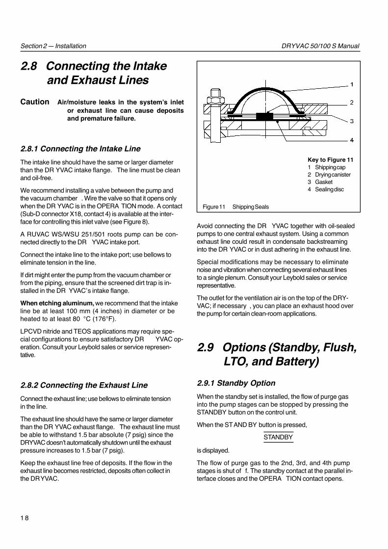
Figure 11 Shipping Seals
Key to Figure 111 Shipping cap2 Drying canister3 Gasket4 Sealing disc
Avoid connecting the DR YVAC together with oil-sealedpumps to one central exhaust system. Using a commonexhaust line could result in condensate backstreaminginto the DR YVAC or in dust adhering in the exhaust line.
Special modifications may be necessary to eliminatenoise and vibration when connecting several exhaust linesto a single plenum. Consult your Leybold sales or servicerepresentative.
The outlet for the ventilation air is on the top of the DRY-VAC; if necessary , you can place an exhaust hood overthe pump for certain clean-room applications.
2.9 Options (Standby, Flush,LTO, and Battery)
2.9.1 Standby OptionWhen the standby set is installed, the flow of purge gasinto the pump stages can be stopped by pressing theSTANDBY button on the control unit.
When the STAND BY button is pressed,
STANDBY
is displayed.
The flow of purge gas to the 2nd, 3rd, and 4th pumpstages is shut of f. The standby contact at the parallel in-terface closes and the OPERA TION contact opens.
1 9
DRYVAC 50/100 S ManualSection 2 — Installation
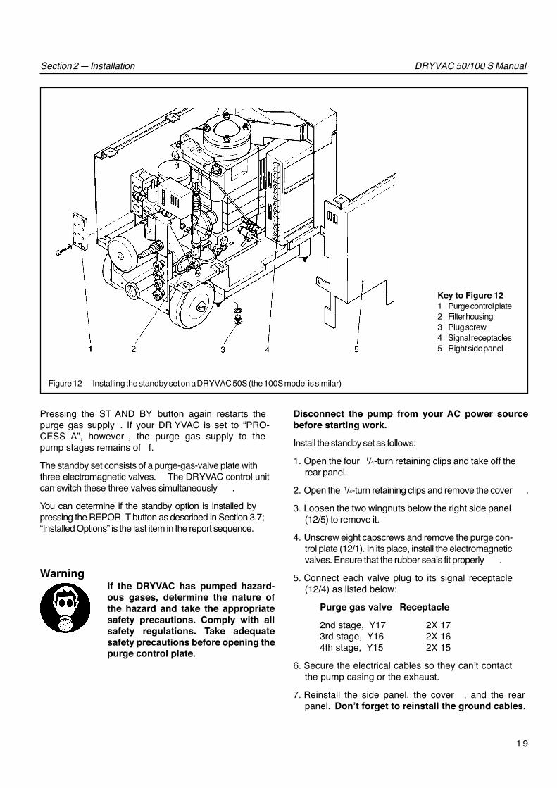
Key to Figure 121 Purge control plate2 Filter housing3 Plug screw4 Signal receptacles5 Right side panel
Figure 12 Installing the standby set on a DRYVAC 50S (the 100S model is similar)
Pressing the ST AND BY button again restarts thepurge gas supply . If your DR YVAC is set to “PRO-CESS A”, however , the purge gas supply to thepump stages remains of f.
The standby set consists of a purge-gas-valve plate withthree electromagnetic valves. The DRYVAC control unitcan switch these three valves simultaneously .
You can determine if the standby option is installed bypressing the REPOR T button as described in Section 3.7;“Installed Options” is the last item in the report sequence.
WarningIf the DRYVAC has pumped hazard-ous gases, determine the nature ofthe hazard and take the appropriatesafety precautions. Comply with allsafety regulations. Take adequatesafety precautions before opening thepurge control plate.
Disconnect the pump from your AC power sourcebefore starting work.
Install the standby set as follows:
1. Open the four 1/4-turn retaining clips and take off therear panel.
2. Open the 1/4-turn retaining clips and remove the cover .
3. Loosen the two wingnuts below the right side panel(12/5) to remove it.
4. Unscrew eight capscrews and remove the purge con-trol plate (12/1). In its place, install the electromagneticvalves. Ensure that the rubber seals fit properly .
5. Connect each valve plug to its signal receptacle(12/4) as listed below:
Purge gas valve Receptacle
2nd stage, Y17 2X 173rd stage, Y16 2X 164th stage, Y15 2X 15
6. Secure the electrical cables so they can’t contactthe pump casing or the exhaust.
7. Reinstall the side panel, the cover , and the rearpanel. Don’t forget to reinstall the ground cables.

2 0
DRYVAC 50/100 S ManualSection 2 — Installation
Key to Figure 131 Purge gas tube, 3rd stage2 Retainer plate3 Nozzle4 Plug screw5 Right side panel6 Flow indicator7 Retaining plate8 Left side panel9 Exhaust silencer
Figure 13 Installing the flush valve and LTO set on a DRYVAC 50S (100S is similar)
2.9.2 Flush Valve OptionWhen the flush option is installed, the pump can beflushed with purge gas by pressing the FLUSH button.
When the FLUSH button is pressed,
FLUSH
is displayed. The flush valve is opened and purge gasflows below the intake port into the pump. If the standbyset is installed, the purge gas valves also open.
The flush valve closes automatically after 5 minutes. Youcan close it sooner by pressing the FLUSH button a sec-ond time.
You can determine if the Flush option is installed bypressing the REPORT button as described in Section 3.7;“Installed Options” is the last item in the report sequence.
WarningIf the DRYVAC has pumped hazardousgases, determine the nature of thehazard and take the appropriatesafety precautions. Comply with allsafety regulations. Take adequatesafety precautions before openingthe purge-gas tubing.
Disconnect the pump from the your AC powersource before starting work.
Proceed as follows to install the flush valve:
1. Remove the DR YVAC panels as follows:a. Open the four 1/4-turn retaining clips and take
off the rear panel.b. Open the 1/4-turn retaining clips and remove the
cover .c. Loosen the two wingnuts below each side panel
(13/8 and 13/5) and remove the left and right sidepanels.
2. Remove plug screw (13/4). In its place, screw the tubecomplete with solenoid valve into the threaded hole onthe intake port.
3. Remove plug screw (12/3) from filter housing (12/2). Inits place, connect the tube from the flush kit. Connectthe other end of this tube to the solenoid valve/tube as-sembly installed in step 2.
4. Connect the valve plug to its signal receptacle (12/4)(receptacle 2X 14).
5. Secure the electrical cables so they can’t contact thepump casing or the exhaust.
6. Reinstall the side panels, the cover , and the rear panel.Don’t forget to reinstall the ground cables.

2 1
DRYVAC 50/100 S ManualSection 2 — Installation
2.9.3 LTO OptionThe LTO set must be installed for processes included inthe “PROCESS C” group (refer to Table 2). It results in alarge flow of purge gas into the 3rd pump stage. The flowindicator for the 3rd stage is also modified. Contact yourLeybold sales or service representative for recommenda-tions for these applications.
You can determine if the L TO option is installed by press-ing the REPORT button as described in Section 3.7; “In-stalled Options” is the last item in the report sequence.
WarningIf the DRYVAC has pumped hazardousgases, determine the nature of thehazard and take the appropriatesafety precautions. Comply with allsafety regulations. Take adequatesafety precautions before openingthe purge-gas tubing.
Disconnect the pump from your AC power source be-fore starting work. Proceed as follows to install the L TOset:
1. Remove the DR YVAC panels as follows:a. Open the 1/4-turn retaining clips and remove the
cover .b. Loosen the two wingnuts below each side panel
(13/8 and 13/5) and remove the left and right sidepanels.
c. Remove the two retainer plates (13/2).
2. Install the new nozzle as follows:a. Pull out the center purge-gas tube (13/1).b. Unscrew the nozzle (13/3) and replace it with the
LTO-set nozzle.c. Reinstall the tube (13/1).
3. Install the new 3rd-stage flow indicator as follows:a. Disconnect the plug of the 3rd-stage flow indicator
from its receptacle 2X 9 (12/4).b. Remove the retaining plate (13/7).c. Pull out the flow indicator (13/6) for the 3rd stage
and replace it with the L TO flow indicator .d. Insert the plug of the L TO flow indicator into signal
receptacle 2X 9.e. Secure the electrical cables so they can’t contact
the pump casing or the exhaust.
4. Reinstall the retaining plates (13/2 and 13/7).
5. Reinstall the side panels and the cover . Don’t forget toreinstall the ground cables.
2.9.4 Battery Backup OptionThe battery backup option affects the pump’s operationas follows:
• It skips the 2-minute initialization period during start-up and after a power failure.
• It keeps the pump running during a short power fail-ure. If the power failure lasts for longer than one sec-ond, the pump shuts down.
• It allows you to restart the pump during the 10-minuterundown by pressing ST ART.
The battery backup option must be installed at our factoryor at one of our service centers.
Before starting the pump, ensure that the second dipswitch (switch 2) is set to the ON (right) position.
The Sub-D connectors on the battery box are identical tothe ones on the pump except for contact 7 of X18. Con-tact 7 of X18 or X18-1 on the battery box sends a failuresignal when the pump is off. Contact 7 of X18 on thepump does not send a failure signal when the pump is off.
The battery is fully charged when you receive the pump,and it recharges as the pump runs. Thus, it is not normallynecessary to recharge the battery . The battery should lastfor about 5 years.
To check the battery , turn of f the main power switch. If thebattery is OK, the background light on the display will dimbut the text will remain visible for about 5 seconds. If thebattery is discharged, the display and text will fade imme-diately when you switch of f power .
If you do need to recharge the battery , turn the pump’ spower switch ON and allow it to recharge for 24 hoursbefore starting the pump.
If you have the AMAT interface PC board installed, thestatus of all X18 interface contacts are the same asshown in Table 3 except that contact 1 & 7 (Fail) are openduring initialization.

2 2
DRYVAC 50/100 S ManualSection 3 — Operation
Figure 14 Control unit display
Note: The FLUSH or STAND BY button operates only if the optional flush or stand-by kit is installed.
3 OperationBefore starting the pump, use the start-up checklist onpage 32 to ensure that the pump is set up properly .
3.1 Start-upCaution Do not open the pump to process gas
until the display indicates “OPERA-TION.” If you open the pump to pro-cess while the display indicates“WAIT,” vapors may condense in thepump.
1. Switch ON the pump.
Initialization
is displayed for about 2 minutes while the DR YVACchecks the settings.You can not operate the DR YVAC until it finishes thisinternal check.
2. Open the inert gas supply; ensure that the inert gaspressure is at least 4 bar abs. (43 psig).
3. Open the compressed air supply; ensure that the airpressure is 6 to 7 bar abs. (72 to 87 psig).
4. Open the cooling water supply .The DRYVAC displays the following:
PROCESS A, B, C, or DReady to start
The STOP LED lights up.
5. Press the ST ART button.The STOP LED goes out and the ST ART LED flashes.
RUN-UP
is displayed.After the pump has run up, it must reach the tempera-ture required for the process that you selected. Whilethe DRYVAC is warming up,
WAITProcess temp. <tmin
is displayed. This WAIT status lasts about 20 to40 minutes.

2 3
DRYVAC 50/100 S ManualSection 3 — Operation
When the pump has reached its process temperature,
OPERATION
is displayed. The DRYVAC is ready to evacuate pro-cess gases.
Section 3.7 describes how to use the REPORT button.The FLUSH and STAND BY buttons operate only if the op-tional flush or stand-by kit is installed on your DR YVAC(refer to Section 2.9).
If the motor protection switch trips when evacuating alarge vacuum chamber , pre-evacuate the chamber witha small diameter line (soft pump line).
3.2 Pumping Non-Aggressive Gases
The DRYVAC is designed to pump aggressive gases dur-ing semiconductor production.
It can also be used to pump clean gases by setting thepump to “PROCESS A” and starting it. When the pumpis in the OPERA TION status, shut of f the inert gas supply .
You can ignore the “W N2 pressure” warning when pump-ing clean gases.
Caution When the inert gas supply is shut off,the shaft seals aren’t protectedagainst dust or against aggressivegases or vapors.
3.3 ShutdownWe recommend that you operate the DR YVAC continu-ously . Allow it to continue operating overnight with its in-let closed to avoid corrosion during idle periods.
To shutdown, press the ST OP button.
RUN-DOWN
is displayed. The pump continues to run for 10 minuteswith the inert gas valve open. The STOP LED flashes.Then the motor is switched off and the main inert gasvalve and the shutof f valve are closed. The STOPLED lights.
In an emergency , you can use the main switch to shut-down the pump without purging. If you shutdown thepump without purging, correct any malfunctions, restartthe pump, and then shut it down with inert-gas purging toremove toxic or hazardous gases from the pump.
Caution If you have a foreline purge, shut offthis purge flow when power is discon-nected from the DRYVAC. Purging theforeline after power is disconnectedcould result in damage to the pumpfrom excessive pressure. The pump’sexhaust valve cannot open to releasethe pressure when power is not avail-able to the pump.
WarningDuring operation, the pump’s tem-perature can exceed 100°C (212°F).Always allow the pump to cool downbefore removing it from the systemor before opening its housing.
WarningIf the DRYVAC previously pumpedhazardous gas, take appropriate pre-cautions before opening the intakeor exhaust.
If the DRYVAC will be shutdown for an extended period,seal its intake and exhaust ports, and purge it with inertgas at a pressure of 1,000 mbar (760 Torr); refer to Sec-tion 3.5.
Refer Section 3.6 if the DR YVAC will be disconnectedfrom the system.
3.4 Response toMalfunctions
Refer to Section 5 (troubleshooting) for the recom-mended corrective actions for each error displayed onthe control unit.
3.4.1 Process Temperature FaultNote: The DRYVAC warning and alarm temperatures re-ferred to in Table 1 are independent of the process; thesetemperature limits are set to prevent excessive tempera-ture from damaging the pump.
2 4
DRYVAC 50/100 S Manual
The operating temperatures listed below are auto-matically set depending on which process groupyou selected in Section 2.6.
Process Group Setting A, B C, D
Thermostat valve setting 4 2
Minimum operating temp. 47°C (117°F) 27°C (81°F)
Maximum operating temp. 63°C (145°F) 43°C (109°F)
If the pump is below the minimum operatingtemperature for the selected process,
Process temp < tmin
is displayed and the pump shifts to the W AIT status.It switches back to the OPERA TION status only afterthe temperature rises 3 °C (5°F) above the minimumoperating temperature.
If the pump is above the maximum operating tempera-ture for the selected process,
Process temp > tmax
is displayed and the pump shifts to the W AIT status.It switches back to the OPERA TION status only afterthe temperature drops 3 °C (5°F) below the maximumoperating temperature.
Thus, there is a delay in returning to the OPERA TIONstatus after a cold start or after a short overheating. Thewait status lasts about 20 to 40 minutes during a normalcold start (refer to Section 3.1).
3.4.2 WarningsWhen the first letter in the display is a “W” (W arning), thepump is approaching a critical operating limit; when thefirst letter is an “A” (Alarm), the pump shuts down be-cause it exceeded a critical limit. Refer to Section 3.4.3for information on Alarms.
If the flow indicator reading does not correspond to theprocess group setting,
W flow 3rd/4th stage
is displayed and the pump switches to the W AIT status.This is the only W arning that changes the pump’ s status.Other warnings, such as “W temperature”, just alert youthat the pump is approaching a critical operating limit, butthey don’t change the pump’s operational mode. When awarning is displayed, determine the source of the prob-lem and correct any malfunctions.
Note: If the DR YVAC is set to “Process A” and it doesnot display the “W N2-Pressure” warning when you shutoff nitrogen to its “dry nitrogen” port, contact Leyboldconcerning the N2-purge retrofit (P/N 200-77-009).
3.4.3 AlarmsWhen the following “A” (alarm) messages are dis-played, the DR YVAC shuts down immediately andautomatically closes the main inert gas valve and theexhaust shutof f valve:• A Motor protection switch
• A Motor contactor
• A Temperature
• A Exhaust pressure
• A Shutof f valve
After eliminating any malfunctions, restart the DR YVACand then shut it down with an inert gas purging cycle.Shutdown with inert gas purging removes toxic or haz-ardous gases from the pump.
3.4.4 Oil Pressure Warning and AlarmThe warning
W Lubrication
is displayed if the oil pressure in the DR YVAC gear boxremains under 1.5 bar (7 psig) for longer than 3 secondswhile the pump is running .
A timer starts when this warning is displayed and beginsdecreasing from 240 minutes (4 hours). The currentcounter reading can be displayed by pressing theREPORT button. The pump automatically shuts down anddisplays
A Lubrication
when the counter reaches zero. This delayed shutdownallows you to complete your process. Following shutdown,the pump must be repaired. After repair , reset the timer to240 minutes as follows:
1. Turn DIP switch 3 ON while the pump is shutdown (seeFigures 6 and 9).
2. Turn the pump ON at the main switch.The message
PROC. SETTINGSet oil t = 4h
Confirm!
is displayed.
3. Press the REPOR T and STOP buttons simultaneously .
The message
Reset switch
is displayed.
Section 3 — Operation

2 5
DRYVAC 50/100 S Manual
WarningHazardous process gas may be re-leased from the DRYVAC or the pro-cess chamber when the exhaust valveopens. Therefore, always disconnectthe pump from the mains beforeworking near the exhaust to preventthe valve from opening. You must alsoshutoff the inert-gas flow to the pumpwhen the exhaust valve can’t open toprevent the pressure in the pumpfrom rising to dangerous levels.
The control unit won’t accept any operator com-mands while the exhaust valve is open in response toan overpressure during a standstill.
3.6 Storing and ShippingShutdown the pump as described in Section 3.3.
WarningsDuring operation, the DRYVAC’s tem-perature can exceed 100°C (212°F).Always allow the pump to cool downbefore removing it from the system orbefore opening its housing.
If the DRYVAC previously pumpedhazardous gases, take appropriateprecautions before opening the intakeor exhaust.
Place drying canisters into the pump’s inlet to protect thepump’ s interior from moisture. Then, seal the DR YVAC’sintake and exhaust ports. You can reuse the shippingseals that were originally on the pump (see Figure 1 1); butyou must use new drying canisters (P/N 200-78-563).
Caution Always drain the cooling water beforestoring or shipping the pump. Failureto drain the water can result in thewater freezing and bursting the pumphousing.
Turn off the cooling water supply and then drain thecooling water as described in the following para-graphs before storing or shipping.
Section 3 — Operation
4. Turn of f DIP switch 3.
Another timer in the control unit records every period thatthe pump ran without oil pressure for more than 3 sec-onds. This counter can’t be reset.
If the oil pressure is below 1.5 bar (7 psig) for more than3 seconds during run-up, the pump switches of f.
3.5 Shutdown for anExtended Period
Press the STOP button. The pump continues to run for10 minutes with the inert gas valve open. Then, the mo-tor switches of f and the main inert-gas valve and the ex-haust valve close.
WarningsDuring operation, the DRYVAC’s tem-perature can exceed 100°C (212°F).Always allow the pump to cool downbefore removing it from the system orbefore opening its housing.
If the DRYVAC previously pumpedhazardous gas, take appropriate pre-cautions before opening the intake orexhaust.
Isolate the pump’s intake port from the system either by avalve or a blank flange, or vent the system and the pumpwith inert gas to a pressure of 1000 mbar (750 T orr).
WarningIf you continue to purge the pump withinert gas after shutdown, avoid exceed-ing a pressure of 1.5 bar (7 psig).
When the pump is at a standstill and the main switch isturned ON, the exhaust valve automatically opens whenthe pressure in the pump’s exhaust exceeds 1.5 bar(7 psig). It closes again when the pressure drops. Thisprocess is repeated as long as incoming inert gas causesthe pressure limit to be exceeded. This protects the pumpfrom a detrimental overpressure at standstill. However ,you should not operate the pump in this way for anextended period.

2 6
DRYVAC 50/100 S Manual
Draining Water From the DRYVAC 100S Model
1. Open the four 1/4-turn retaining clips on the rearpanel, and take of f the panel.
2. Open the thermostat valve to a setting less than 1.
3. Disconnect the cooling water hoses and drain thewater. Then blow out the cooling water lines with com-pressed air .
4. Reinstall the rear panel.
Draining Water From the DRYVAC 50S Model
1. Open the four 1/4-turn retaining clips and take of fthe rear panel.
2. Loosen the 1/4-turn retaining clips on top of thepump and remove the top cover .
3. Loosen the two wingnuts below the left side paneland remove the panel.
4. Completely open the thermostat valve.
5. Disconnect the cooling water hoses; remove theM12x1.5 plug screw (2/8); and let the water drain out.Then blow out the cooling water lines with compressedair.
6. Reinstall the plug screw , left side panel, top cover , andrear panel.
The DRYVAC must be shipped either in a gas tight con-tainer or sealed in plastic.
If the pump will be returned to Leybold, it must be accom-panied by a listing of all hazardous substances whichmight be present in or around it. Complete the form at theback of this manual before sending any equipment toLeybold.
3.7 Report(REPORT button)
Press the REPOR T button to display information aboutthe pump’ s operational status. Refer to Section 5, thetroubleshooting chart, for the recommended correctiveactions for each error report.
When the REPORT button is pressed,
DRYVAC V (Software-version) REPORT
is displayed. Each report is displayed for 3 seconds be-fore automatically moving on to the next report.
Information is displayed in the following sequence:
Stored alarms (A’s), such as:• A Temperature
• A Exhaust pressure
• A Shutoff valve
• A Motor protection switch
• A Motor contactor
• A Lubrication
These stored alarms indicate why the pump was shut-down.
Current alarms (A’s) — These are the same as thestored alarms except that the pump isn’t ready to re-start. Correct the malfunction before restartingthe pump.
Warnings (W’s), such as:• Process temp < tmin
• Process temp > tmax
• W Temperature
• W Exhaust pressure
• W Lubrication
• W N2 pressure
• W Flow
Warnings mean that the pump is nearing a critical limitbut is still fully operational. Determine the reason forthe warning and correct any malfunction as soonas possible.For the “W N2 pressure” or “W flow” Warnings,you must shut off the process gas if the malfunctioncan’t be eliminated immediately . Operating withoutpurge will eventually cause serious damage to theDRYVAC. Refer to Section 3.2 if you are pumpingclean gases.
Operating hours — Displays the total hours the unit hasoperated.
Process Temperature — Displays its cooling watertemperature in °C.
Section 3 — Operation

2 7
DRYVAC 50/100 S Manual
Lubr. Lack — If the oil pressure in the gear housinghas always been normal, the DR YVAC displays:
Lubr lack DV(4h) 240
and then:
Lubr lack DV 000.0 h
If the oil pressure is inadequate, the first display showsless than 4 hours (240 minutes). This indicates the timeremaining until the DR YVAC shuts down because ofinsufficient oil pressure (refer to Section 3.4.4).The second display shows the total cumulative time theDRYVAC has run with inadequate oil pressure. If theDRYVAC has never operated with inadequate oil pres-sure, the second display will indicate 000.0 hours.
Process Setting — Displays the process you selectedsuch as A, B, C, or D (refer to Table 2 and Sec-tion 2.6).
Installed Option — Displays any installed options assuch as:• Standby set
• Flush valve
• LTO set
If no options are installed, it skips this item.
The report can be interrupted by pressing the REPORTbutton again. It can be restarted at any time.
Stored alarms can be ignored when the DR YVAC is beingput into operation for the first time. If an error report isdisplayed when the DR YVAC is switched on, you mustpress the REPOR T button before starting the DR YVAC.
Once all malfunctions have been eliminated, you can re-start the pump by pressing the ST ART button. This erasesall stored error reports.
Section 3 — Operation

2 8
DRYVAC 50/100 S Manual
4 Maintenance
4.1 Routine MaintenanceThe DRYVAC may require rebuilding periodically de-pending on your application and your production cycle.In some installations, the rebuild interval may vary from 12to 24 months. If you seldom need to clean the inlet andexhaust lines, then the rebuild interval could belonger . Contact your Leybold service center for rec-ommendations on rebuild intervals for your particularinstallation. Also ask about the service options availablein your region.
Typically , the only other routine maintenance is replacing theexhaust silencer if it becomes clogged (see Sec. 4.2).
All work must be done by suitably trained personnel.Maintenance or repair done by inexperienced personnelmay affect the life and performance of the pump and mayvoid the warranty .
WarningsDisconnect the DRYVAC from your ACpower source before maintaining orrepairing the pump. Take appropriateprecautions to ensure that the pumpcannot be started.
During operation, the DRYVAC’s tem-perature can exceed 100ºC (212ºF).Always allow the pump to cool beforeremoving it from the system or beforeopening its housing.
If the DRYVAC has pumped hazardousgases, determine the nature of thehazard and take the appropriatesafety precautions. Comply with allsafety regulations.
Before doing any maintenance or repair , shutdown theDRYVAC as described in Section 3.3 and disconnect itfrom the system. Refer to Section 3.6 to prepare thepump for shipping.
Caution Always drain the cooling water beforestoring or shipping the DRYVAC. Fail-ure to drain the water can result inthe water freezing and bursting theDRYVAC housing.
If the DRYVAC will be returned to Leybold, it must be ac-companied by a listing of all hazardous substances thatmight be present in or around it. Complete the form at theback of this manual before sending any equipment to Leybold.
4.2 Replacing the ExhaustSilencer
The spin-on exhaust silencer (13/9) may need to be re-placed periodically in certain processes.As deposits build up in the exhaust silencer , the DRYVACexhaust pressure increases until,
W Exhaust pressure
is displayed. The DRYVAC can continue to operate; how-ever, the exhaust silencer must be changed as soon aspossible. Otherwise, the exhaust pressure will continue toincrease until the DR YVAC switches of f and
A Exhaust pressure
is displayed.Refer to Item 7 of the troubleshooting chart for other pos-sible causes of excessive exhaust pressure.
WarningsDisconnect the DRYVAC from yourAC power source before removingthe exhaust silencer. Take appropri-ate precautions to ensure that thepump cannot be started.During operation, the DRYVAC’s tem-perature can exceed 100°C (212°F).Always allow the pump to cool beforeremoving it from the system or beforeopening its housing.If the DRYVAC has pumped hazardousgases, determine the nature of thehazard and take the appropriatesafety precautions. Comply with allsafety regulations.
Change the exhaust silencer (P/N 137 50) as follows:1. Open the four 1/4-turn retaining clips and take of f
the rear panel.2. Use the Allen key supplied with the pump, and a 17-mm
wrench to unscrew the exhaust silencer (13/9).3. Unscrew the shipping cover from the new exhaust si-
lencer .4. Apply PFPE grease on the gasket of the new exhaust
silencer .5. Install the exhaust silencer and tighten it to 20 Nm
(27 ft-lb).The shipping cover can be used to seal the old exhaustsilencer .
Caution Comply with local environmentalregulations when disposing of the oldexhaust silencer.
Section 4 — Maintenance

2 9
DRYVAC 50/100 S Manual
Motor circuit switch 1Q2 is turned off.Errors in the main power connection.
One of the malfunctions listed below at 6, 7,8 or 12 has been detected.
The position indicator at the exhaust shutoffvalve is malfunctioning.The pump has seized causing the motorprotection switch to trip during start-up
Motor is malfunctioning.Pump is rotating in the wrong direction.
Insufficient lubricant in the gearbox.
Unsuitable measurement procedure or gauge.
Purge gas supply is open
The pump has an external leak.Optional flush valve is leaking or will not close.Evaporating liquids in the pump.
Vacuum chamber is leaking or dirtyIntake line is leaking or dirty.Intake line is too long or too narrow.
Dirt trap in the intake port is clogged.Pump is contaminted by deposits.Pump rotation speed is too slow.
System or intake line is leaking.The pump has an external leak.
* This column refers to the section in the Operating instructions that contains the applicable repair information.
Section 5 — Troubleshooting
5 TroubleshootingMalfunction/Display at theControl Unit
Probable Cause Refer-ences*Recommended Corrective Action
2.3.12.3
3.7
Service
Service
Service2.7
Service
---
2.9.1
Service2.9.2---
------2.8.1
---ServiceName-plate2.3---Service
1.1 Pump does notstart/No display
1.2 Pump does notstart/“ STOP” LEDlights up.
1.3 Pump runs upbriefly, then“W Lubrication”is displayed.
2. Pump does notreach ultimatepressure
3. Evacuation periodis too long.(Pumping speedis too low.)
4. The pressure inthe system risestoo quickly afterthe pump shutsdown.
Open the door at the front; turn switch on.Check and rectify the wiring. Verify that themain supply voltage is correct.Refer to the descriptions of malfunctions under6, 7, 8 & 12. Press the REPORT button toreview the error report.Repair the exhaust shutoff valve.
Repair the pump. If it does not start, checkwhether it turns freely by removing the middlesegment of the top cover, and use a 5-mmAllen key (200 mm long) to turn the motor shaftfrom the outside.Repair the pump.Shut off power to the pump. Interchange two ofthe phase leads.Measure the oil level via the fill plug. The targetvalue is 6 to 9 mm ( 1/4 to 3/8 inch) for the 100Sand 12 to 15 mm (1/2 to 5/8 inch) for the 50S.Measure pressure at pump’s intake port usingsuitable gauge.If you have the STANDBY option and if theprocess permits, use the STAND BY button toclose the purge-gas valve.Find the leak; repair the pump.Replace the valve.Measure the partial pressure of the non-condensable gases. To do so, insert a low-temperature trap between the gauge and theintake port. If the ultimate pressure is achievedwhile this trap is operating, liquids are evaporat-ing in the pump. One possible remedy: Openthe purge gas valve and let the pump run1/2 hour without process load.Seal or clean the vacuum chamber.Seal or clean the intake line.Install intake lines that have an adequatediameter; keep lines as short as possible.Clean dirt trap.Clean the pump.Check whether the frequency of your AC powersource complies with the specifications for thispump.Check the system and the intake line.Repair the pump.

3 0
DRYVAC 50/100 S Manual
Bearings are malfunctioning.Liquid “knocking” in the pump (too muchliquid in the pump).
Insufficient air pressure at the exhaustshutoff valve.Supply of compressed air was interruptedbriefly.Switch, plug, or cable malfunction.
Exhaust line is clogged.Exhaust line is too narrow or too long.
Exhaust shutoff valve is malfunctioning.Exhaust silencer is clogged.Switch, plug, or cord malfunction.
Process gas is too hot.Ambient temperature is too high.Cooling air flow is restricted.
Friction in the pump is too high.The switch, plug, or cable is malfunctioning.
Pump is in the warm-up phase.
Cooling water supply is not opened.Cooling water pressure is too low.Cooling water flow is too low.Cooling water temperature is too high.
Lime deposits in the cooling water lines tothe pump. During normal operation, thecooling water temperature will be below70°C (158°F). At these temperatures,deposits form very slowly. Early clogging isan indication of some operational difficulty.Dirt deposits in the pump’s cooling waterchannels.Cooling water lines are connected incorrectly.The thermostat valve is set incorrectly.The pump was not filled with cooling waterduring installation.Switch, plug, or cable is malfunctioning.
5. The pump isextremely loud.
6. “ A Shutoffvalve” isdisplayed.
7. Exhaust pressure
“ W Exhaustpressure” isdisplayed first. If itcontinues to rise“A Exhaustpressure” isdisplayed and thepump switchesoff.
8. Temperature
“ W Temperature”is displayed first.If it continues torise, “ A Tempera-ture” is displayedand the pumpswitches off.
9. “ ProcessTemperature<tmin or >tmax”is displayed.
Service2.8.2
2.5
2.5
Service
---2.8.2
Service4.1Service
---------
ServiceService
3.1
---2.4
Service
Service
2.42.42.4
Service
Repair the pump.Install the exhaust line so that it slopes down-ward from the pump, or install a condensatetrap. Increase the purge gas supply.Ensure that the compressed air supply is atleast 6 bar (72 psig).Ensure that the compressed air supply is atleast 6 bar (72 psig).Replace the malfunctioning part. Switch circuitbreakers ON.Clean the exhaust line.Install an exhaust line which is large enough,and is as short as possible.Replace the valve.Replace the exhaust silencer.Replace the malfunctioning part. Switch thecircuit breakers ON.
Change the process.Change pump site or supply cooler air.Clean the ventilation grids and the cooling airducts; increase the distance between the gridsand the walls.Repair the pump.Replace the malfunctioning part. Switch thecircuit breakers ON.
Wait until the pump has reached its processtemperature.Turn ON the cooling water supply.Ensure that there is an adequate supply ofcooling water: pressure 2–10 bar (14–130 psig) ,consumption about 100 l/hr (100 qt/hr) at watertemperature of 15 °C (59°F). The max. coolingwater inlet temperature is 25 °C (77°F).Repair the pump.
Dismantle the pump and clean the coolingwater channels.Connect the cooling water lines correctly.Set the thermostat valve correctly.Fill the pump with cooling water.
Replace the malfunctioning part; switch thecircuit breakers ON.
Section 5 — Troubleshooting
* This column refers to the section in the Operating instructions that contains the applicable repair information.
Malfunction/Display at theControl Unit
Probable Cause Refer-ences*Recommended Corrective Action

3 1
DRYVAC 50/100 S Manual
10. Oil pressure
First“W Lubrication”is displayed.After 4 hours,“A Lubrication”is displayed andthe pump isswitched off.See Sect. 3.4.4.
11. Either “ W N2-pressure” or“ W Flow” isdisplayed.
12. “ A Motorprotectionswitch” isdisplayed
(the motorprotectionswitch hastripped).
13. “ Key notallowed” isdisplayed
14. “ Call errorreport” isdisplayed
15. “ Remoteoperation” isdisplayed
16. “ Process notallowed” isdisplayed
17. “ Wrong proc.setting” isdisplayed
18. “Confirm” isdisplayed
The pump is rotating in the wrong direction;see malfunction 1.3.Insufficient oil in the gear box.
The oil pump is malfunctioning.Switch, plug, or cable malfunction.
The inert-gas valve is not open.Insufficient inert gas pressure.
The purge-gas valves are restricted.The main inert-gas valve is restricted.
The purge-gas nozzles are dirty.The purge-gas valve plate or purge-gas linewas mounted incorrectly during pumpconversion.Switch, plug, or cable is malfunctioning.
The intake pressure is too high.The pump has seized.
Main supply voltage is too low.Ambient temperature is too high.Switch, plug, or cable malfunction.
---The user pressed the FLUSH or STAND BYbuttons which function only if the FLUSH orSTANDBY options have been installed.When this is displayed, review the errorreport.
The pump is set to remote operation at theinterface.
Process setting isn’t allowed since animportant option is absent.
More than one process has been set at theDIP switches.
---
2.7
Service
ServiceService
---2.5
ServiceFigure 7Service
Service2.9.1/2.9.3
Service
---Service
2.3---Service
Figure 72.9.1 and2.9.2
3.7
2.3.2
2.6/2.9.3
2.6
2.6
Shut off power to the pump. Interchange two ofthe phase leads.Measure the oil level via the fill plug. The targetvalue is 6 to 9 mm ( 1/4 to 3/8 inch) for the 100Sand 12 to 15 mm (1/2 to 5/8 inch) for the 50S.Repair the pump.Replace the malfunctioning part. Switch circuitbreakers ON.
Open the inert gas supply.Set the correct inert gas pressure (4–10 bar,43–130 psig).Replace the valves.Replace the valve. The valve is closed whendeenergized. If it does not open, check thepower supply, connections, and fuses.Clean the nozzles.Correctly install the purge-gas valve plate orpurge-gas line.
Replace the malfunctioning part. Switch circuitbreakers ON.Modify the system.Repair the pump. If the pump doesn’t start,check whether it turns freely. Remove themiddle segment of the top cover and use a5-mm Allen key (200 mm long) to turn themotor shaft from the outside.Connect the pump to the correct voltage.Change the site or ensure a cooler air supply.Replace the malfunctioning part. Switch thecircuit breakers ON.Switch the motor protection switch ON.Press permissible buttons.
Press the REPORT button.
Open the REMOTE contact at the parallelinterface.
Install option or select another process.
Set only a single process.
Press the STOP and REPORT keyssimultaneously.
Section 5 — Troubleshooting
* This column refers to the section in the Operating instructions that contains the applicable repair information.
Malfunction/Display at theControl Unit
Probable Cause Refer-ences*Recommended Corrective Action

3 2
DRYVAC 50/100 S Manual
Start-up ChecklistHave you read the installation &start-up instructions in this manual? .......❐Is the pump converted for the process? ...❐Is mains voltage correct for your pumpmodel (see Section 2.3)? ........................... ❐Is pump set to the correct mains voltage ..❐Are cooling water inlet and outletconnected correctly? ................................ ❐Is pump filled with cooling water? ............. ❐Is thermostat valve set to correctprocess? .................................................. ❐Is inert gas connected (4-10 bar ,43-130 psig)? ........................................... ❐Is compressed air connected (6-7 bar ,72-86 psig)? ............................................. ❐Are DIP switches set to correct process? ...❐Is the main switch turned ON? .................. ❐Is the process confirmed(REPORT + STOP)? ................................. ❐Are the shipping seals removed? .............. ❐Is the direction of rotation correct? .......... ❐Are the enclosure panels reinstalled? ....... ❐Is the intake line equipped for theprocess (see Section 2.8.1)? ................... ❐Is the intake line clean and oil free? ......... ❐Is the intake line connected with bellows? ...❐Is the exhaust line connected to aproper exhaust system? ............................ ❐Are the inlet and exhaust lines freeof leaks? ................................................... ❐Is the inert gas supply open? .................... ❐Is the compressed air supply open? ......... ❐Is the cooling water supply open? ............ ❐Is the exhaust line open and free ofdeposits? .................................................. ❐Are the preset process group and“Ready to Start” displayed? ...................... ❐Press the start button and wait for thepump to reach its process temperature.
Process Settings
Process DIP Thermo- Purge Optiongroup switches stat valve control plate Required
A 5 ON 4 closed —
B 6 ON 4 open —
C 7 ON 2 open LTO
D 8 ON 2 open —
Start-up: Date: ________ Name: _________________________ Dept.: ___________Remarks: