Drying cellulose nanofibrils: in search of a suitable … · Drying cellulose nanofibrils: in...
12
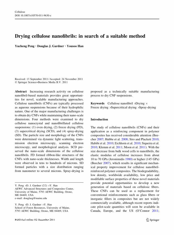
Drying cellulose nanofibrils: in search of a suitable method Yucheng Peng • Douglas J. Gardner • Yousoo Han Received: 13 September 2011 / Accepted: 24 November 2011 Ó Springer Science+Business Media B.V. 2011 Abstract Increasing research activity on cellulose nanofibril-based materials provides great opportuni- ties for novel, scalable manufacturing approaches. Cellulose nanofibrils (CNFs) are typically processed as aqueous suspensions because of their hydrophilic nature. One of the major manufacturing challenges is to obtain dry CNFs while maintaining their nano-scale dimensions. Four methods were examined to dry cellulose nanocrystal and nanofibrillated cellulose suspensions: (1) oven drying, (2) freeze drying (FD), (3) supercritical drying (SCD), and (4) spray-drying (SD). The particle size and morphology of the CNFs were determined via dynamic light scattering, trans- mission electron microscopy, scanning electron microscopy, and morphological analysis. SCD pre- served the nano-scale dimensions of the cellulose nanofibrils. FD formed ribbon-like structures of the CNFs with nano-scale thicknesses. Width and length were observed in tens to hundreds of microns. SD formed particles with a size distribution ranging from nanometer to several microns. Spray-drying is proposed as a technically suitable manufacturing process to dry CNF suspensions. Keywords Cellulose nanofibril Á Drying Á Freeze drying Á Supercritical drying Á Spray-drying Introduction The study of cellulose nanofibrils (CNFs) and their application as a reinforcing component in polymer composites has received considerable attention (Bee- cher 2007; Hubbe et al. 2008; Siro and Plackett 2010; Habibi et al. 2010; Eichhorn et al. 2010; Siqueira et al. 2010; Klemm et al. 2011; Moon et al. 2011). With the size decrease from bulk wood cells to nanofibrils, the elastic modulus of cellulose increases from about 10 to 70 GPa (Jeronimidis 1980) or higher (145 GPa) (Beecher 2007), which results in significant mechan- ical property improvement for cellulose nanofibril- reinforced polymer composites. The biodegradability, low density, worldwide availability, low price and modifiable surface properties of these novel materials provide potential opportunities to develop a new generation of materials based on cellulosic fibers. These CNFs can be used as a replacement for conventional reinforcements such as glass fibers or inorganic fillers in composites but are not widely commercially available, although recent reports indi- cate pilot-scale quantities will soon be available in Canada, Europe, and the US (O’Connor 2011; Y. Peng Á D. J. Gardner (&) Á Y. Han AEWC Advanced Structures and Composites Center, University of Maine, 5793 AEWC Building, Orono, ME 04469, USA e-mail: [email protected] Y. Peng Á D. J. Gardner Á Y. Han School of Forest Resources, University of Maine, 5793 AEWC Building, Orono, ME 04469, USA 123 Cellulose DOI 10.1007/s10570-011-9630-z
Transcript of Drying cellulose nanofibrils: in search of a suitable … · Drying cellulose nanofibrils: in...
Drying cellulose nanofibrils: in search of a suitable method
Yucheng Peng • Douglas J. Gardner • Yousoo Han
Received: 13 September 2011 / Accepted: 24 November 2011
� Springer Science+Business Media B.V. 2011
Abstract Increasing research activity on cellulose
nanofibril-based materials provides great opportuni-
ties for novel, scalable manufacturing approaches.
Cellulose nanofibrils (CNFs) are typically processed
as aqueous suspensions because of their hydrophilic
nature. One of the major manufacturing challenges is
to obtain dry CNFs while maintaining their nano-scale
dimensions. Four methods were examined to dry
cellulose nanocrystal and nanofibrillated cellulose
suspensions: (1) oven drying, (2) freeze drying (FD),
(3) supercritical drying (SCD), and (4) spray-drying
(SD). The particle size and morphology of the CNFs
were determined via dynamic light scattering, trans-
mission electron microscopy, scanning electron
microscopy, and morphological analysis. SCD pre-
served the nano-scale dimensions of the cellulose
nanofibrils. FD formed ribbon-like structures of the
CNFs with nano-scale thicknesses. Width and length
were observed in tens to hundreds of microns. SD
formed particles with a size distribution ranging
from nanometer to several microns. Spray-drying is
proposed as a technically suitable manufacturing
process to dry CNF suspensions.
Keywords Cellulose nanofibril � Drying �Freeze drying � Supercritical drying � Spray-drying
Introduction
The study of cellulose nanofibrils (CNFs) and their
application as a reinforcing component in polymer
composites has received considerable attention (Bee-
cher 2007; Hubbe et al. 2008; Siro and Plackett 2010;
Habibi et al. 2010; Eichhorn et al. 2010; Siqueira et al.
2010; Klemm et al. 2011; Moon et al. 2011). With the
size decrease from bulk wood cells to nanofibrils, the
elastic modulus of cellulose increases from about
10 to 70 GPa (Jeronimidis 1980) or higher (145 GPa)
(Beecher 2007), which results in significant mechan-
ical property improvement for cellulose nanofibril-
reinforced polymer composites. The biodegradability,
low density, worldwide availability, low price and
modifiable surface properties of these novel materials
provide potential opportunities to develop a new
generation of materials based on cellulosic fibers.
These CNFs can be used as a replacement for
conventional reinforcements such as glass fibers or
inorganic fillers in composites but are not widely
commercially available, although recent reports indi-
cate pilot-scale quantities will soon be available in
Canada, Europe, and the US (O’Connor 2011;
Y. Peng � D. J. Gardner (&) � Y. Han
AEWC Advanced Structures and Composites Center,
University of Maine, 5793 AEWC Building, Orono,
ME 04469, USA
e-mail: [email protected]
Y. Peng � D. J. Gardner � Y. Han
School of Forest Resources, University of Maine,
5793 AEWC Building, Orono, ME 04469, USA
123
Cellulose
DOI 10.1007/s10570-011-9630-z
Vartiaine et al. 2011; Bloch 2011). In most cases,
CNFs are processed as aqueous suspensions because
of their hydrophilic nature and propensity to agglom-
erate during drying (Gardner et al. 2008). There is a
well perceived need to develop robust processes to dry
CNF which will maintain nano-scale dimensions for
materials applications where a dry form is necessary
and, secondarily, to mitigate the higher transportation
costs of the aqueous suspensions. Having a dried form
of CNF is especially important in the field of
thermoplastic processing like extrusion or injection
molding where thermal melting processes are
encountered. During thermal melting processes with
non-polar thermoplastics, water is a detriment to
satisfactory processing. Therefore, drying of aqueous
suspensions of CNFs and understanding the drying
process are necessary for their utilization in develop-
ing industrially relevant polymer nanocomposites.
Four different forms of cellulose fibrils on the nano-
scale can be prepared (Gardner et al. 2008). Two of
them were studied in this research work. With wood
pulp as the raw material, CNFs are manufactured by
two general methods: mechanical fibrillation and
chemical hydrolysis. The corresponding products are
referred to as nanofibrillated cellulose (NFC) and
cellulose nanocrystals (CNC), respectively. NFC is
obtained by processing dilute slurries of cellulose
fibers through grinding or high-pressure homogeniz-
ing action while the production of cellulose nanocrys-
tals involves the digestion of amorphous cellulosic
domains by an acid hydrolysis process (Herrick et al.
1983; Hubbe et al. 2008). After manufacturing, an
evenly dispersed CNF aqueous suspension occurs as a
colloidal system. The strong hydrogen bonds among
water and cellulose particles enable the system to
remain thermally or kinetically stable throughout a
range of water contents. Water can penetrate into
amorphous regions of NFC while it can only hydrogen
bond to the surfaces of CNCs or to the crystalline
regions of NFCs. The adsorbed water on cellulose
fibers is categorized into three different states based on
the thermodynamic property of water: free water,
freezing bound water, and nonfreezing bound water
(Nakamura et al. 1981). Free water is defined as bulk
water with the same thermal characteristics of pure
water. Freezing bound water is water reacted with
hydroxyl groups on cellulose molecules; the transition
temperature is lower than pure water because of the
restriction of reactions between water and cellulose
fibers. Nonfreezing bound water is defined as a subset
of bound water with a non-detectable thermal transi-
tion. At the same time, nonfreezing bound water is
interpreted as water reacting with hydroxyl groups of
cellulose molecules directly while freezing bound
water is located relatively far away from the hydroxyl
groups (Weise et al. 1996). Some of the freezing
bound water molecules might not be bound to the
hydroxyl groups, but are still close enough to be
influenced by these hydrophilic groups and exhibit a
depressed transition temperature.
Removing water from CNF suspensions to maintain
nano-scale dimensions of the nanofibrils is a delicate
process. Dehydration of CNF suspensions using eth-
anol showed significant increase in nanofibril diameter
(Thimm et al. 2000). The existence of air–water
interfaces with fibril-sized curvature in the suspensions
may exert sufficient attractive capillary pressures to
displace fibrils from their original positions. These
capillary forces have been demonstrated by pulling
adjacent fibers together in the wet state of paper (Lyne
and Galay 1954). At the same time, mutual diffusion of
nano-scale fibrils at interfacing surfaces may also drive
the CNFs to agglomerate. The molecular segments of
cellulose fibrils which are partially dissolved in water
(Clark 1985) tend to mix in the wet state, resulting in
interpenetration and tangling among the nano-scale
cellulose fibrils (McKenzie 1984; Pelton 1993). In
addition, hydrogen bonds and Van der Waals forces are
expected to hold the fibrils together after the removal
of water (Hiemenz and Rajagopalan 1997; Hunter
2001). Hydrogen bonding among CNFs requires that
hydroxyl groups at the facing surfaces approach each
other within 0.25–0.35 nm, i.e. molecular contact. For
dispersion forces (Van der Waals) to occur, the
distances among nanofibrils need to be closer than
the distances for hydrogen bonds (Hiemenz and
Rajagopalan 1997; Lindstrom et al. 2005). In a stable
CNF suspension, the distances among fibrils are not
small enough to form molecular contact. During
drying, forces resulting from the removal of water
and high temperatures may drive the molecular contact
of CNFs and cause agglomeration. The objective of our
study is to identify a suitable drying process to produce
reasonable quantities of dry cellulose nanofibrils.
Three methods are proposed to dry the CNFs:
freeze drying, spray-drying, and supercritical drying
(Pakowski 2007). Oven drying of CNF suspensions
will be performed as a control.
Cellulose
123
Experimental
Suspension preparation
Two CNF suspensions were involved: (1) a commer-
cial product of NFC suspension ARBOCEL MF40–10
at 10 wt. % from J. Rettenmaier & Sohne
GMBH?CO.KG, Germany, and (2) a CNC suspen-
sion at 6.5 wt. % from the Forest Products Laboratory
in Madison, Wisconsin. Before drying, distilled water
was added into the original suspensions and mixed
using a Speed Mixer� (Flack Tek Inc., US) for 4 min
at 2,000 rpm to obtain final weight concentrations of
CNC and NFC suspensions at 0.001, 0.1, and 2%.
Dynamic light scattering (DLS)
Measurements of all cellulose nanofibril suspensions
at 0.1 wt. % were made with a Zetasizer Nano ZS
(Malvern Instruments, Malvern UK) using a detection
angle of 173� at a temperature of 25 �C. The viscosity
value for water was used in all measurements. The
Nano ZS uses a 4mW He–Ne laser operating at a
wavelength of 633 nm. The intensity size distributions
were obtained from analysis of the correlation func-
tions using the Multiple Narrow Modes algorithm in
the instrument software. This algorithm is based upon
a non-negative least squares fit (Lawson and Hanson
1995; Desobry et al. 1997). These intensity particle
size distributions were converted into volume using
Mie theory (Mie 1908).
Transmission electron microscopy (TEM)
Drops of 0.001 wt. % NFC and CNC suspensions were
deposited on carbon coated electron microscope grids
and negatively stained with 2 wt. % uranyl acetate.
The grids were dried in air and observed with a Philips
CM10 Transmission Electron Microscope operated at
an acceleration voltage of 80 kV.
Drying of suspensions
Different drying methods were applied to the suspen-
sions just after mixing. Oven drying (OD) was
performed at 105 �C for 24 h in glass beakers. Prior
to freeze drying (FD), CNF suspensions (about 20 mL)
were frozen in vials at a temperature of -80 �C for
24 h. Frozen suspensions were then transferred to a
Virtis Freezemobile 25 SL freeze dryer, which has a
condenser temperature of -80 �C and a vacuum of 11
mTorr. Lyophilization was allowed to continue for
72 h. Supercritical drying (SCD) of the prepared
suspension was conducted on the Tousimis Samdri
PVT-3 Critical-Point dryer. Four steps were involved
in this process: (1) dehydration of aqueous suspension
with a series of ethanol solutions (50, 75, 95, and
100%) was performed before drying until water was
completely replaced with ethanol, (2) replacement of
ethanol with liquid CO2, and (3) liquid CO2 and the
cellulose mixture is pressurized and heated to the
supercritical conditions, and (4) the liquid CO2 is
eliminated by decompression to the atmosphere. A
novel spray-drying method was conducted using a
Mini Spray Dryer B-290 (Buchi, Switzerland). Details
of the spray drying process are the subject of a
provisional patent application.
Scanning electron microscopy (SEM)
SEM studies on the morphologies of dried samples
were carried out using an AMR 1000 (AMRay Co.)
scanning electron microscope. All samples were
sputter-coated with gold before the microscopic
observations were obtained. SEM images were taken
at an accelerating voltage of 10 kV at various
magnifications.
Particle size analysis
Quantitative characterization of particle size distribu-
tion was conducted using a Morphologi G3S system
(Malvern, UK). The Morphologi G3S system provides
the ability to measure the morphological characteris-
tics (size and shape) of particles. The principle of the
operation is based on digital image analysis utilizing
an optical microscope. A sample is prepared and
placed on the measurement slide or plate. Then the
sample is scanned with transmitted or reflected light
and high-resolution digital images are produced.
Using the optical microscope under this situation, a
two dimensional (2D) projected image of the three
dimensional (3D) particles are obtained. The captured
high-resolution image is then analyzed with the
integrated analysis software to obtain the particle size
characteristics. The area of captured 2D image for
each particle is converted to a circle of same area and
the diameter of the circle is reported as the circle
Cellulose
123
equivalent (CE) diameter of the particle. During the
2D image capturing process, a technique called Z
stacking can be used to better characterize the 3D
particles. A 3D particle sitting on the measurement
plate cannot be completely in contact with the bottom
plate surface. Since the objective lens of the instru-
ment exhibits a narrow depth of field under high
magnification, accurate focus cannot always be
achieved across the entire body of a 3D particle. Z
stacking is a utility that takes several images of the
sample, each at different Z heights (Z axis is the
direction normal to the measurement plate) and then
overlays to form a single composite image. In this
study, identical volumes of CNC and NFC powders
(5 mm3) were uniformly dispersed onto a glass plate
using an integrated sample dispersion unit (SDU) with
a dispersing pressure 0.5 MPa, injection time 10 ms,
and settling time 60 s. The powder sample is first
placed in a holder of SDU and held by 25 lm carrier
foils. Another carrier foil is placed in the top of the
holder. Air pressure is then applied to break the foil and
the resulting turbulence disperses the samples onto the
measurement glass plate uniformly. After dispersion, a
suitable objective lens was chosen according to the
particle sizes. In this work, an objective lens of 509
which corresponds to 2,468 times magnification was
selected to take the 2D image of the three dimensional
(3D) particles. Z stacking with additional two layers
above initial focus was used to take three images of the
sample, each at different Z heights (0, 3.6, and 7.3 lm)
and then overlays to form a single composite image.
Image analysis converted the captured image for each
particle to a circle of same area and the circle
equivalent (CE) diameter distribution of the charac-
terized particles were reported as the particle size
distribution.
Results and discussion
Characterization of cellulose nanofibrils
in suspension
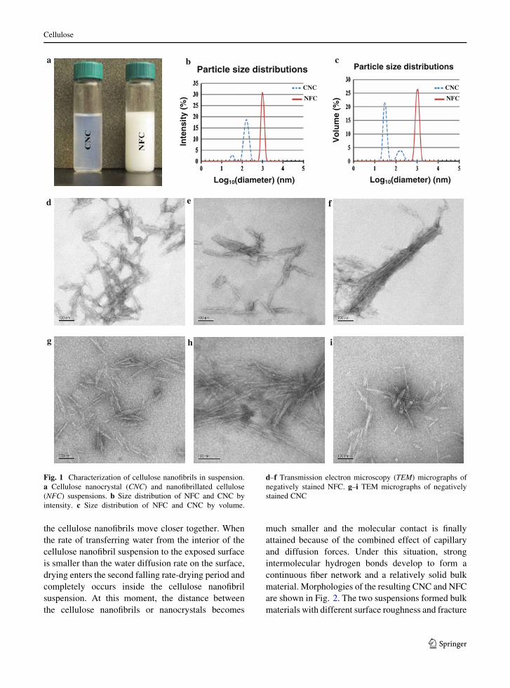
The prepared NFC and CNC suspensions at 2 wt. %
are shown in Fig. 1a. The NFC suspension is milky
white while the CNC suspension is a bluish translucent
solution. Quantitative characterization of cellulose
nanofibril size distributions in suspensions was per-
formed on a 0.1 wt. % suspension using dynamic light
scattering (DLS). The obtained hydrodynamic diam-
eter distributions of NFC and CNC at 0.1 wt. % are
shown in Fig. 1b by intensity. A single peak at around
1,000 nm (from 712 to 1,484 nm) was observed on the
NFC size distribution curve while two peaks at around
of 35 (from 24 to 44 nm) and 165 nm (from 91 to
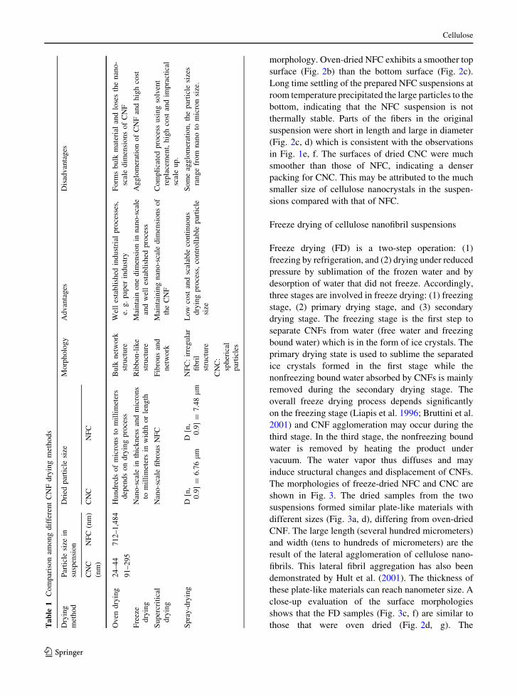
295 nm) were on the CNC curve (Table 1). Based on
the Mie theory (Mie 1908), size distributions can be
converted into volume distribution as shown in
Fig. 1c. The size distribution by volume is slightly
different than the measured size distribution by
intensity. For CNC, a volume of about 76% is in the
particle size range of 21–51 nm while about 24% are
in the size range of 79–342 nm. The dimensions of
NFC and CNC in suspension were also examined
directly using a transmission electron microscope and
the obtained micrographs of NFC and CNC are shown
in Fig. 1d, i. Both NFC and CNC showed needlelike
fibrils (Fig. 1d, g). NFC showed greater dimensions
(diameter and length) than those of CNC, as indicated
by the DLS measurement. A portion of relatively short
and large cell wall sections (chunks) in the NFC
suspension were also observed (Fig. 1e, f). A large
aggregation of many individual fibrils was also
observed in Fig. 1f. At the same time, entanglement
of NFC (Fig. 1e) and CNC (Fig. 1h, i) fibrils occurred
when air dried at a concentration of 0.001 wt. %.
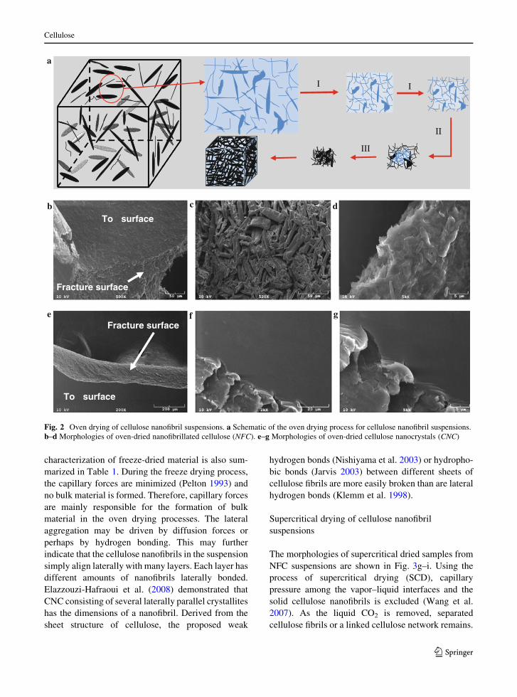
Oven drying of cellulose nanofibril suspensions
Oven drying (OD) was conducted by exposing the
suspensions in a conventional laboratory oven at
105 �C with circulating air. The schematic of the
drying process is shown in Fig. 2a. Water evaporation
can be divided into three parts (Brinker and Scherer
1990; Scherer 1990; Mujumdar and Devahastin 2000):
(1) the constant rate-drying period, (2) the first falling
rate-drying period, and (3) the second falling rate-
drying period. In the constant rate drying period, CNFs
move together with the shrinkage of suspension
volume as water evaporates. In this process, the
capillary forces which are mainly used to move
cellulose nanofibrils increases as a function of water
evaporation. When the cellulose nanofibril surface or
partial surfaces are exposed, the first falling rate-
drying period begins and water evaporation primarily
takes place over the cellulose nanofibril surfaces.
The capillary tension reaches a maximum value and
vapor diffusion begins to take over. Simultaneously,
Cellulose
123
the cellulose nanofibrils move closer together. When
the rate of transferring water from the interior of the
cellulose nanofibril suspension to the exposed surface
is smaller than the water diffusion rate on the surface,
drying enters the second falling rate-drying period and
completely occurs inside the cellulose nanofibril
suspension. At this moment, the distance between
the cellulose nanofibrils or nanocrystals becomes
much smaller and the molecular contact is finally
attained because of the combined effect of capillary
and diffusion forces. Under this situation, strong
intermolecular hydrogen bonds develop to form a
continuous fiber network and a relatively solid bulk
material. Morphologies of the resulting CNC and NFC
are shown in Fig. 2. The two suspensions formed bulk
materials with different surface roughness and fracture
d
a b c
e f
g h i
Particle size distributions
Inte
nsi
ty (
%)
Log10(diameter) (nm)
Particle size distributions
Vo
lum
e (%
)
Log10(diameter) (nm)
NFC
CNC
NFC
CNC
Fig. 1 Characterization of cellulose nanofibrils in suspension.
a Cellulose nanocrystal (CNC) and nanofibrillated cellulose
(NFC) suspensions. b Size distribution of NFC and CNC by
intensity. c Size distribution of NFC and CNC by volume.
d–f Transmission electron microscopy (TEM) micrographs of
negatively stained NFC. g–i TEM micrographs of negatively
stained CNC
Cellulose
123
morphology. Oven-dried NFC exhibits a smoother top
surface (Fig. 2b) than the bottom surface (Fig. 2c).
Long time settling of the prepared NFC suspensions at
room temperature precipitated the large particles to the
bottom, indicating that the NFC suspension is not
thermally stable. Parts of the fibers in the original
suspension were short in length and large in diameter
(Fig. 2c, d) which is consistent with the observations
in Fig. 1e, f. The surfaces of dried CNC were much
smoother than those of NFC, indicating a denser
packing for CNC. This may be attributed to the much
smaller size of cellulose nanocrystals in the suspen-
sions compared with that of NFC.
Freeze drying of cellulose nanofibril suspensions
Freeze drying (FD) is a two-step operation: (1)
freezing by refrigeration, and (2) drying under reduced
pressure by sublimation of the frozen water and by
desorption of water that did not freeze. Accordingly,
three stages are involved in freeze drying: (1) freezing
stage, (2) primary drying stage, and (3) secondary
drying stage. The freezing stage is the first step to
separate CNFs from water (free water and freezing
bound water) which is in the form of ice crystals. The
primary drying state is used to sublime the separated
ice crystals formed in the first stage while the
nonfreezing bound water absorbed by CNFs is mainly
removed during the secondary drying stage. The
overall freeze drying process depends significantly
on the freezing stage (Liapis et al. 1996; Bruttini et al.
2001) and CNF agglomeration may occur during the
third stage. In the third stage, the nonfreezing bound
water is removed by heating the product under
vacuum. The water vapor thus diffuses and may
induce structural changes and displacement of CNFs.
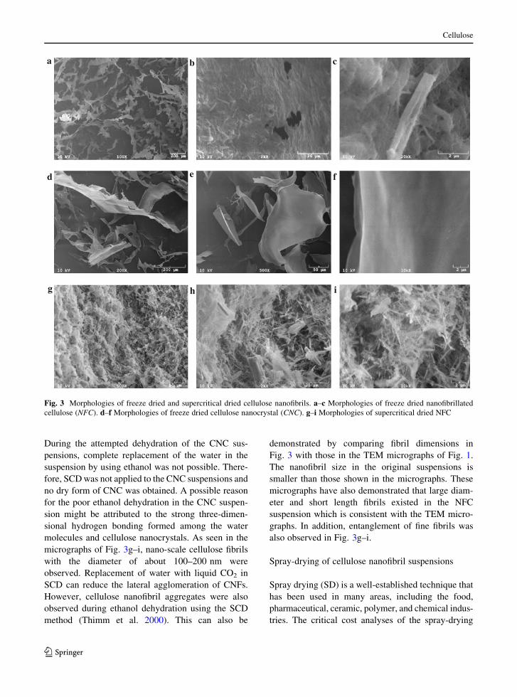
The morphologies of freeze-dried NFC and CNC are
shown in Fig. 3. The dried samples from the two
suspensions formed similar plate-like materials with
different sizes (Fig. 3a, d), differing from oven-dried
CNF. The large length (several hundred micrometers)
and width (tens to hundreds of micrometers) are the
result of the lateral agglomeration of cellulose nano-
fibrils. This lateral fibril aggregation has also been
demonstrated by Hult et al. (2001). The thickness of
these plate-like materials can reach nanometer size. A
close-up evaluation of the surface morphologies
shows that the FD samples (Fig. 3c, f) are similar to
those that were oven dried (Fig. 2d, g). TheTa
ble
1C
om
par
iso
nam
on
gd
iffe
ren
tC
NF
dry
ing
met
ho
ds
Dry
ing
met
hod
Par
ticl
esi
zein
susp
ensi
on
Dri
edp
arti
cle
size
Mo
rph
olo
gy
Ad
van
tages
Dis
advan
tag
es
CN
C
(nm
)
NF
C(n
m)
CN
CN
FC
Ov
end
ryin
g2
4–
44
71
2–
1,4
84
Hu
nd
reds
of
mic
ron
sto
mil
lim
eter
sd
epen
ds
on
dry
ing
pro
cess
Bu
lkn
etw
ork
stru
ctu
reW
ell
esta
bli
shed
indust
rial
pro
cess
es,
e.g
.p
aper
ind
ust
ryF
orm
sb
ulk
mat
eria
lan
dlo
ses
the
nan
o-
scal
ed
imen
sion
so
fC
NF
91
–2
95
Fre
eze
dry
ing
Nan
o-s
cale
inth
ick
nes
san
dm
icro
ns
tom
illi
met
ers
inw
idth
or
len
gth
Rib
bo
n-l
ike
stru
ctu
reM
ain
tain
on
ed
imen
sio
nin
nan
o-s
cale
and
wel
les
tabli
shed
pro
cess
Ag
glo
mer
atio
no
fC
NF
and
hig
hco
st
Su
per
crit
ical
dry
ing
Nan
o-s
cale
fib
rou
sN
FC
Fib
rou
san
d
net
wo
rk
Mai
nta
inin
gn
ano
-sca
led
imen
sio
ns
of
the
CN
F
Com
pli
cate
dp
roce
ssu
sing
solv
ent
repla
cem
ent,
hig
hco
stan
dim
pra
ctic
alsc
ale
up
.
Sp
ray
-dry
ing
D[n
,0
.9]
=6
.76
lmD
[n,
0.9
]=
7.4
8lm
NF
C:
irre
gu
lar
fib
ril
stru
ctu
re
Lo
wco
stan
dsc
alab
leco
nti
nuo
us
dry
ing
pro
cess
,co
ntr
oll
able
par
ticl
e
size
So
me
agg
lom
erat
ion
,th
ep
arti
cle
size
sra
ng
efr
om
nan
oto
mic
ron
size
.
CN
C:
sph
eric
alp
arti
cles
Cellulose
123
characterization of freeze-dried material is also sum-
marized in Table 1. During the freeze drying process,
the capillary forces are minimized (Pelton 1993) and
no bulk material is formed. Therefore, capillary forces
are mainly responsible for the formation of bulk
material in the oven drying processes. The lateral
aggregation may be driven by diffusion forces or
perhaps by hydrogen bonding. This may further
indicate that the cellulose nanofibrils in the suspension
simply align laterally with many layers. Each layer has
different amounts of nanofibrils laterally bonded.
Elazzouzi-Hafraoui et al. (2008) demonstrated that
CNC consisting of several laterally parallel crystallites
has the dimensions of a nanofibril. Derived from the
sheet structure of cellulose, the proposed weak
hydrogen bonds (Nishiyama et al. 2003) or hydropho-
bic bonds (Jarvis 2003) between different sheets of
cellulose fibrils are more easily broken than are lateral
hydrogen bonds (Klemm et al. 1998).
Supercritical drying of cellulose nanofibril
suspensions
The morphologies of supercritical dried samples from
NFC suspensions are shown in Fig. 3g–i. Using the
process of supercritical drying (SCD), capillary
pressure among the vapor–liquid interfaces and the
solid cellulose nanofibrils is excluded (Wang et al.
2007). As the liquid CO2 is removed, separated
cellulose fibrils or a linked cellulose network remains.
I
II
III
I
b
a
c d
e f g
To surface
Fracture surface
To surface
Fracture surface
Fig. 2 Oven drying of cellulose nanofibril suspensions. a Schematic of the oven drying process for cellulose nanofibril suspensions.
b–d Morphologies of oven-dried nanofibrillated cellulose (NFC). e–g Morphologies of oven-dried cellulose nanocrystals (CNC)
Cellulose
123
During the attempted dehydration of the CNC sus-
pensions, complete replacement of the water in the
suspension by using ethanol was not possible. There-
fore, SCD was not applied to the CNC suspensions and
no dry form of CNC was obtained. A possible reason
for the poor ethanol dehydration in the CNC suspen-
sion might be attributed to the strong three-dimen-
sional hydrogen bonding formed among the water
molecules and cellulose nanocrystals. As seen in the
micrographs of Fig. 3g–i, nano-scale cellulose fibrils
with the diameter of about 100–200 nm were
observed. Replacement of water with liquid CO2 in
SCD can reduce the lateral agglomeration of CNFs.
However, cellulose nanofibril aggregates were also
observed during ethanol dehydration using the SCD
method (Thimm et al. 2000). This can also be
demonstrated by comparing fibril dimensions in
Fig. 3 with those in the TEM micrographs of Fig. 1.
The nanofibril size in the original suspensions is
smaller than those shown in the micrographs. These
micrographs have also demonstrated that large diam-
eter and short length fibrils existed in the NFC
suspension which is consistent with the TEM micro-
graphs. In addition, entanglement of fine fibrils was
also observed in Fig. 3g–i.
Spray-drying of cellulose nanofibril suspensions
Spray drying (SD) is a well-established technique that
has been used in many areas, including the food,
pharmaceutical, ceramic, polymer, and chemical indus-
tries. The critical cost analyses of the spray-drying
d
a
e f
g h i
b c
Fig. 3 Morphologies of freeze dried and supercritical dried cellulose nanofibrils. a–c Morphologies of freeze dried nanofibrillated
cellulose (NFC). d–f Morphologies of freeze dried cellulose nanocrystal (CNC). g–i Morphologies of supercritical dried NFC
Cellulose
123
process have encouraged the acceptance of spray-
drying as a standard industrial dehydration method
(Hardy 1955; Quinn 1965). One of the major concerns
about the inefficiency of the spray-drying process (low
solid contents requirements) has also been eliminated
(Quinn 1965). The relatively low labor and mainte-
nance costs demonstrate that spray-drying can be used
for those applications where specific product charac-
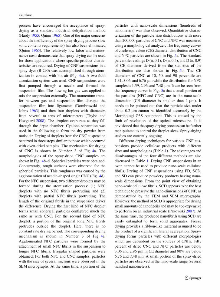
teristics are required. Drying of CNF suspensions in a
spray dyer (B-290) was accomplished through atom-
ization in contact with hot air (Fig. 4a). A two-fluid
atomization system was used. CNF suspensions were
first pumped through a nozzle and formed the
suspension film. The flowing hot gas was applied to
mix the suspension externally. The momentum trans-
fer between gas and suspension film disrupts the
suspension film into ligaments (Dombrowski and
Johns 1963) and then into droplets with diameters
from several to tens of micrometers (Thybo and
Hovgaard 2008). The droplets evaporate as they fall
through the dryer chamber. Cyclone separation was
used in the following to form the dry powder from
moist air. Drying of droplets from the CNC suspension
occurred in three steps similar to those which occurred
with oven-dried samples. The mechanism for drying
of CNC is shown in Number 2 of Fig. 4a. The
morphologies of the spray-dried CNC samples are
shown in Fig. 4b–d. Spherical particles were obtained.
Concurrently, rough surfaces were observed for the
spherical particles. This roughness was caused by the
agglomeration of needle-shaped single CNC (Fig. 4d).
For the NFC suspension, two different droplets may be
formed during the atomization process: (1) NFC
droplets with no NFC fibrils protruding and (2)
droplets with partial NFC fibrils protruding. The
length of the original fibrils in the suspension drives
the difference. Drying the first kind of NFC droplet
forms small spherical particles configured much the
same as with CNC. For the second kind of NFC
droplet, a portion of the original long NFC fibrils
protrudes outside the droplet. Here, there is no
constant rate drying period. The corresponding drying
mechanism is shown in Number 3 of Fig. 4a.
Agglomerated NFC particles were formed by the
attachment of small NFC fibrils in the suspension to
longer NFC fibrils. Irregular shaped particles were
obtained. For both NFC and CNC samples, particles
with the size of several microns were observed in the
SEM micrographs. At the same time, a portion of the
particles with nano-scale dimensions (hundreds of
nanometers) was also observed. Quantitative charac-
terization of the particle size distributions with more
than 200,000 particles of CNC and NFC was measured
using a morphological analyzer. The frequency curves
of circle equivalent (CE) diameter distribution of CNC
and NFC particles are shown in Fig. 5a. The standard
percentile readings D (n, 0.1), D (n, 0.5), and D (n, 0.9)
of CE diameter derived from the statistics of the
distribution are also shown in Fig. 5b. The CE
diameters of CNC at 10, 50, and 90 percentile are
1.31, 3.06, and 6.76 lm while the distribution for NFC
samples is 1.59, 2.96, and 7.48 lm. It can be seen from
the frequency curves in Fig. 5a that a small portion of
the particles (NFC and CNC) are in the nano-scale
dimension (CE diameter is smaller than 1 lm). It
needs to be pointed out that the particle size under
about 0.2 lm cannot be identified accurately by the
Morphologi G3S equipment. This is caused by the
limit of resolution of the optical microscope. It is
envisioned that the spray-drying process can be further
manipulated to control the droplet sizes. Spray-drying
studies are currently ongoing.
Different drying techniques for various CNF sus-
pensions provide cellulose products with different
sizes and morphologies (Table 1). The advantages and
disadvantages of the four different methods are also
discussed in Table 1. Drying CNF suspensions in an
oven cannot be used to produce nano-scale cellulose
fibrils. Drying of CNF suspensions using FD, SCD,
and SD can produce powdery products having nano-
scale dimensions. From the point view of obtaining
nano-scale cellulose fibrils, SCD appears to be the best
technique to preserve the nano-dimensions of CNF, as
demonstrated by the TEM and SEM micrographs.
However, the method of SCD is appropriate for drying
small amounts of nanofibrils and may be too expensive
to perform on an industrial scale (Pakowski 2007). At
the same time, the produced nanofibrils using SCD are
easily entangled to form solid aggregates. Freeze
drying provides a ribbon-like material assumed to be
the product of a significant lateral aggregation. Spray-
drying forms particles with different morphologies
which are dependent on the sources of CNFs. Fifty
percent of dried CNC and NFC particles are below
3.06 and 2.96 lm in CE diameter and 90% are below
6.76 and 7.48 lm. A small portion of the spray-dried
particles are observed in the nano-scale range (several
hundred nanometers).
Cellulose
123
Spray Gas jet
Gas
Gas
Suspension
Suspension film Ligament Droplet
1. Suspension film break-up process
Droplet Vapor CNC Dried CNC
2. Drying of CNC droplet
b
a
c d
e f g
3. Drying of NFC droplet
NFC Dried NFC Vapor Droplet
Fig. 4 Spray-drying of cellulose nanofibril suspensions. a Mechanism of spray-drying process. b–d Morphologies of spray-dried
cellulose nanocrystal (CNC). e–g Morphologies of spray-dried nanofibrillated cellulose (NFC)
Cellulose
123

In term of process economics, as reported by the
food industry (Filkova et al. 2007) or the flavor
industry (Desobry et al. 1997), freeze drying is
5–10 times more expensive than spray-drying. In
addition, involving solvent exchange in the process
of supercritical drying complicates the drying process
and makes this process expensive (Pakowski 2007).
Based on the results obtained by examining the
various lab scale drying methods, spray-drying is
proposed to be a suitable manufacturing process which
can be used to dry cellulose nanofibril suspensions.
Conclusions
The morphological properties of the dried cellulose
nanofibrils are dependent on the particular drying
method and the starting materials (NFC and CNC).
The agglomeration mechanisms occurring among the
cellulose nanofibrils are different for each drying
method. SCD and FD created highly networked
structures of cellulose agglomerates with multi-scalar
dimensions including the nano-scale. An agglomera-
tion mechanism was introduced for the SD method,
showing how the dried particulates could be formed.
Only the SD method produced particulates of dried
cellulose which, range in size from nano to micron,
and are viewed as potentially suitable for use as
additives or fillers in composite manufacturing utiliz-
ing conventional thermoplastic compounding tech-
niques. The highly-networked structures of dried
cellulose from SCD and FD may limit the use of the
products in particular composite applications since the
difficulties in dispersion would remain as a barrier in
conventional thermoplastic compounding. In terms of
nano material production from cellulose suspensions,
SD is suggested for its potential capability to create
particulates on the nano-scale.
Acknowledgments The authors acknowledge the US Army
Corps of Engineers, Engineering R&D Center, and the Maine
Agricultural and Forestry Experiment Station McIntire-Stennis
Project ME09615-06 for financial support. The content and
information does not necessarily reflect the position of the
funding agencies. Maine Agricultural and Forest Experiment
Station Publication Number 3242.
References
Beecher JF (2007) Organic materials: wood, trees and nano-
technology. Nat Nanotechnol 2:466–467
Bloch J (2011) UMaine to build nation’s only cellulose nano-
fibrils pilot plant. http://umaine.edu/news/blog/2011/10/
28/umaine-to-build-nation’s-only-cellulose-nanofibrils-
pilot-plant/
Brinker CJ, Scherer GW (1990) Drying. In: Brinker CJ, Scherer
GW (eds) Sol-gel science: the physics and chemistry of sol-
gel processing, 1st edn. Academic Press Limited, London,
pp 453–513
Bruttini R, Grosser OK, Liapis AI (2001) Energy analysis for the
freezing stage of the freeze drying process. Dry Technol
19:2303–2314
Clark JD’A (1985) Fibrillation and fiber bonding. In: Clark
JD’A (ed) Pulp technology and treatment for paper,
2nd edn. Miller Freeman Publications, San Francisco,
pp 160–180
Desobry SA, Netto FM, Labuza TP (1997) Comparison of
spray-drying, drum-drying and freeze-drying for b-Caro-
tene encapsulation and preservation. J Food Sci 62:
1158–1162
Dombrowski N, Johns WR (1963) The aerodynamic instability
and disintegration of viscous liquid sheets. Chem Eng Sci
18:203–214
Eichhorn SJ, Dufresne A, Aranguren M, Marcovich NE, Ca-
padona JR, Rowan SJ, Weder C, Thielemans W, Roman M,
Renneckar S, Gindl W, Veigel S, Keckes J, Yano H, Abe K,
Nogi M, Nakagaito AN, Mangalam A, Simonsen J, Benight
AS, Bismarck A, Berglund LA, Peijs T (2010) Review:
CE diameter (µm)
Sample D(n,0.1) D (n, 0.5) D (n, 0.9)
CNC 1.31 3.06 6.76
NFC 1.59 2.96 7.48
b a
CNC NFC
Fig. 5 Particle size distributioin of spray-dried cellulose
nanofibrils. a Frequency curves of number based circle
equivalent diameter (CE) of nanofibrillated cellulose (NFC)
and cellulose nanocrystal (CNC). b The standard percentile
readings of CE diameter distribution of NFC and CNC in a
Cellulose
123
current international research into cellulose nanofibres and
nanocomposites. J Mater Sci 45:1–33
Elazzouzi-Hafraoui S, Nishiyama Y, Putanus J, Heux L, Deb-
reuil F, Rochas C (2008) The shape and size distribution of
crystalline nanoparticles prepared by acid hydrolysis of
native cellulose. Biomacromolecules 9:57–65
Filkova I, Huang LX, Mujumdar AS (2007) Industrial spray
drying systems. In: Mujumdar AS (ed) Hankbook of
industrial drying, 3rd edn. CRC Press, New York,
pp 215–254
Gardner DJ, Oporto GS, Mills R, Samir MASA (2008) Adhesion
and surface issues in cellulose and nanocellulose. J Adhes
Sci Technol 22:545–567
Habibi Y, Lucia LA, Rojas OJ (2010) Cellulose nanocrystals:
chemistry, self-assembly, and applications. Chem Rev
110:3479–3500
Hardy WL (1955) Costs process and construction-spray drying
cost analysis shows labor is largest item, utilizes constant.
Ind Eng Chem 47:73A–74A
Herrick FW, Casebier RL, Hamilton JK, Sandberg KR (1983)
Microfibrillated cellulose: morphology and accessibility.
J Appl Polym Sci Appl Polym Symp 37:797–813
Hiemenz PC, Rajagopalan R (1997) Principles of colloid and
surface science. CRC Press, New York
Hubbe MA, Rojas OJ, Lucia LA, Sain M (2008) Cellulosic
nanocomposites: a review. BioResources 3(3):929–980
Hult EL, Larsson PT, Iversen T (2001) Cellulose fibrils aggre-
gation—an inherent property of kraft pulps. Polymer
42:3309–3314
Hunter RJ (2001) Foundations of colloid science. Oxford Univ.
Press, Oxford
Jarvis M (2003) Cellulose stacks up. Nature 426:611–612
Jeronimidis G (1980) Wood, one of nature’s challenging com-
posites. Symp Soc Exp Biol 34:169–182
Klemm D, Philipp B, Heinze T, Heinze U, Wagenknecht W
(1998) Comprehensive cellulose chemistry. Volume 1,
fundamentals and analytical methods. Wiley-VCH, New
York
Klemm D, Kramer F, Moritz S, Lindstrom T, Ankerfors M, Gray
D, Dorris A (2011) Nanocelluloses: a new family of nature-
based materials. Angew Chem Int Ed 50:5438–5466
Lawson CL, Hanson RJ (1995) Solving least squares problems.
Society for industrial and applied mathematics (SIAM),
Philadelphia
Liapis AI, Pikal MJ, Bruttini R (1996) Research and develop-
ment needs and opportunities in freeze-drying. Dry Tech-
nol 14:1265–1300
Lindstrom T, Wagberg L, Larsson T (2005) On the nature of
joint strength in paper- a review of dry and wet strength
resins used in paper manufacturing. In: Proceedings of 13th
fundamental research symposium, Cambridge, Pira Inter-
national, Leatherhead
Lyne LM, Galay W (1954) Studies in the fundamentals of wet
web strength. Tappi 37(12):698–704
McKenzie AW (1984) The structure and properties of paper.
Part XXI: the diffusion theory of adhesion applied to
interfiber bonding. Appita 37(7):580–583
Mie G (1908) Beitrage zur optic truber medien, speziell kol-
loidaler metallosungen. Ann Physik 4:377–445
Moon RJ, Marini A, Nairn J, Simonsen J, Youngblood J (2011)
Cellulose nanomaterials review: structure, properties and
nanocomposites. Chem Soc Rev 40:3941–3994
Mujumdar AS, Devahastin S (2000) Fundamental principles of
drying. In: Devahastin S (ed) Mujumdar’s practical guide
to industrial drying. Exergex Vorp, Montreal, pp 1–22
Nakamura K, Hatakeyma T, Hatakeyma H (1981) Studies on
bound water of cellulose by differential scanning calo-
rimetry. J Textile Inst 72(9):607–613
Nishiyama Y, Sugiyama J, Chanzy H, Langan P (2003) Crystal
structure and hydrogen bonding system in cellulose I alpha
from synchrotron X-ray and neutron fiber diffraction. J Am
Chem Soc 125:14300–14306
O’Connor B (2011) Ensuring the safety of manufactured nano-
crystalline cellulose: a risk assessment under Canada’s
new substances notification regulations. http://www.
tappi.org/content/events/11nano/paper/11Nano03.pdf.
Accessed 21 June 2011
Pakowski Z (2007) Modern methods of drying nanomaterials.
Transp Porous Med 66:19–27
Pelton R (1993) A model of the external surface of wood pulp
fibers. Nordic Pulp Paper Res J 8(1):113–119
Quinn JJ (1965) The economics of spray drying. Ind Eng Chem
57:35–37
Scherer GW (1990) Theory of drying. J Am Ceram Sco 73:3–14
Siqueira G, Bras J, Dufresne A (2010) Cellulosic bionano-
composites: a review of preparation, properties and appli-
cations. Polymers 2:728–765
Siro I, Plackett D (2010) Microfibrillated cellulose and new
nanocomposite materials: a review. Cellulose 17:459–494
Thimm JC, Burritt DJ, Ducker WA, Melton LD (2000) Celery
(Apium graveolens L.) parenchyma cell walls examined by
atomic force microscopy: effect of dehydration on cellu-
lose microfibrils. Planta 212:25–32
Thybo P, Hovgaard L (2008) Droplet size measurements for
spray dryer scale-up. Pharm Dev Technol 13:93–104
Vartiaine J, Pohler T, Sirola K, Pylkkanen L, Alenius H,
Hokkinen J, Tapper U, Lahtine P, Kapanen A, Putkisto K,
Hiekkataipale P, Eronen P, Ruokolainen J, Laukkanen A
(2011) Health and environmental safety aspects of friction
grinding and spray drying of microfibrillated cellulose.
Cellulose 18:775–786
Wang B, Huang LX, Mujumdar AS (2007) Drying of nanosize
products. In: Mujumdar AS (ed) Hankbook of industrial
drying, 3rd edn. CRC Press, New York, pp 713–727
Weise U, Maloney T, Paulapuro H (1996) Quantification of
water in different states of interaction with wood pulp
fibres. Cellulose 3:189–202
Cellulose
123