DRY BENEFICIATION OF HIGH ASH NON- COKING...
33
NATIONAL INSTITUTE OF TECHNOLOGY ROURKELA A THESIS SUBMITTED In partial fulfillment of the requirements of Bachelor of Technology (Chemical Engineering) SUBMITTED BY ASISH KUMAR SAHOO 10500001 Session: 2008-09 Under the Guidance of Prof. G. K. Roy Department of Chemical Engineering National Institute of Technology Rourkela 2009 “DRY BENEFICIATION OF HIGH ASH NON- COKING COAL USING AN AIR DENSE MEDIUM FLUIDIZED BED”
Transcript of DRY BENEFICIATION OF HIGH ASH NON- COKING...

NATIONAL INSTITUTE OF TECHNOLOGY
ROURKELA
A THESIS SUBMITTED
In partial fulfillment of the requirements of
Bachelor of Technology (Chemical Engineering)
SUBMITTED BY
ASISH KUMAR SAHOO
10500001 Session: 2008-09
Under the Guidance of
Prof. G. K. Roy Department of Chemical Engineering
National Institute of Technology Rourkela 2009
“DRY BENEFICIATION OF HIGH ASH NON-COKING COAL USING AN AIR DENSE
MEDIUM FLUIDIZED BED”

National Institute of Technology
Rourkela
CERTIFICATE
This is to certify that the thesis entitled, “DRY BENEFICIATION OF HIGH
ASH NON-COKING COAL USING AN AIR DENSE MEDIUM FLUIDIZED
BED” submitted by Sri Asish Kumar Sahoo in partial fulfillments of the requirements for
the award of Bachelor of Technology Degree in Chemical Engineering at National
Institute of Technology, Rourkela (Deemed University) is an authentic work carried out
by him under my supervision and guidance.
To the best of my knowledge, the matter embodied in the thesis has not been
submitted to any other University / Institute for the award of any Degree or Diploma.
Date:
Rourkela (Prof. G. K. Roy)
Dept. of Chemical Engineering,
National Institute of Technology
Rourkela - 769008, Orissa

ACKNOWLEDGEMENT
I would like to make my deepest appreciation and gratitude to Prof. G. K. Roy for his
valuable guidance, constructive criticism and encouragement during every stage of this
project.
Thanks to Prof. R. K. Singh for being uniformly excellent advisor. He was always
open, helpful and provided strong broad idea. I am also thankful to Prof. (Mrs) S. Mishra
for helping me in procuring some of the utilities related to this project.
I would like to express my gratitude to Prof. K. C. Biswal (HOD) for giving me
permission for my visit to IMMT(CSIR), Bhubaneswar and UCIL, Jadugoda Mines,
Jharkhand for procuring material and providing me the necessary opportunities for the
completion of my project.
Grateful acknowledgement is made to Mr A. Mohanty for his all time technical
support in carrying out the experiments, the Laboratory assistants Mr Jhaja Nayak and Mr
Rajendra Tirkey for helping me in the Fuel Lab, Mechanical Operations and Fluid Flow
Laboratory.
I would also like to extend my sincere thanks to all of them inside and outside
NIT Rkl for their kind co-operation and sincere help. In spite of the numerous citations
mentioned, the author accepts full responsibility for the contents that follow.
Rourkela
Date: ASISH KUMAR SAHOO
Dept. of Chemical Engineering,
National Institute of Technology, Rourkela - 8

CONTENTS
Page No ABSTRACT 1
1.SIGNIFICANCE OF THE PROJECT 2
1.1 WHY DRY BENEFICIATION 2
2. HISTORY AND DEVELOPMENT 4
3. AIR DENSE MEDIUM FLUIDIZED BED BENEFICIATION (SEPARATION) PROCESS 5
3.1 PRINCIPLE OF AIR DENSE MEDIUM FLUIDIZED BED SEPARATOR 5
3.2 MATHEMATICAL EQUATIONS FOR CHECKING DYNAMIC STABILITY OF BED 6
3.3 SEPARATION MECHANISM WITH AIR DENSE MEDIUM FLUIDIZED BED 7
4. MATERIALS AND UTILITIES 12
4.1 MATERIALS 12
4.2 UTILITIES 12
5. EXPERIMENTAL 13
5.1 EXPERIMENTAL SET UP 13
5.2 EXPERIMENTAL PROCEDURE 13
5.2.1 FOR CHECKING THE BED STABILITY 13
5.2.2 FOR DRY BENEFICIATION OF COARSE HIGH ASH COAL 14
5.2.3 SAMPLE COLLECTION PROCEDURE 15
6. INTERPRETATION OF EXPERIMENTAL DATA 16
6.1 STUDY OF DISTRIBUTOR BEHAVIOUR 16
6.2 BED STABILITY ANALYSIS IN 50 MM DIA SETUP 16
6.3 BED STABILITY ANALYSIS IN 100 MM DIA SETUP 18
6.4 COAL ENRICHMENT ANALYSIS 20
7. RESULTS AND DISCUSSIONS 21
7.1 DEVELOPMENT OF CORRELATION 21
7.2 DISCUSSION ON RESULTS AND CONCLUSION 24
8. POTENTIAL APPLICATION OF THE PRESENT PROJECT WORK 25
9. NOTATIONS 26
10. REFERENCES 27
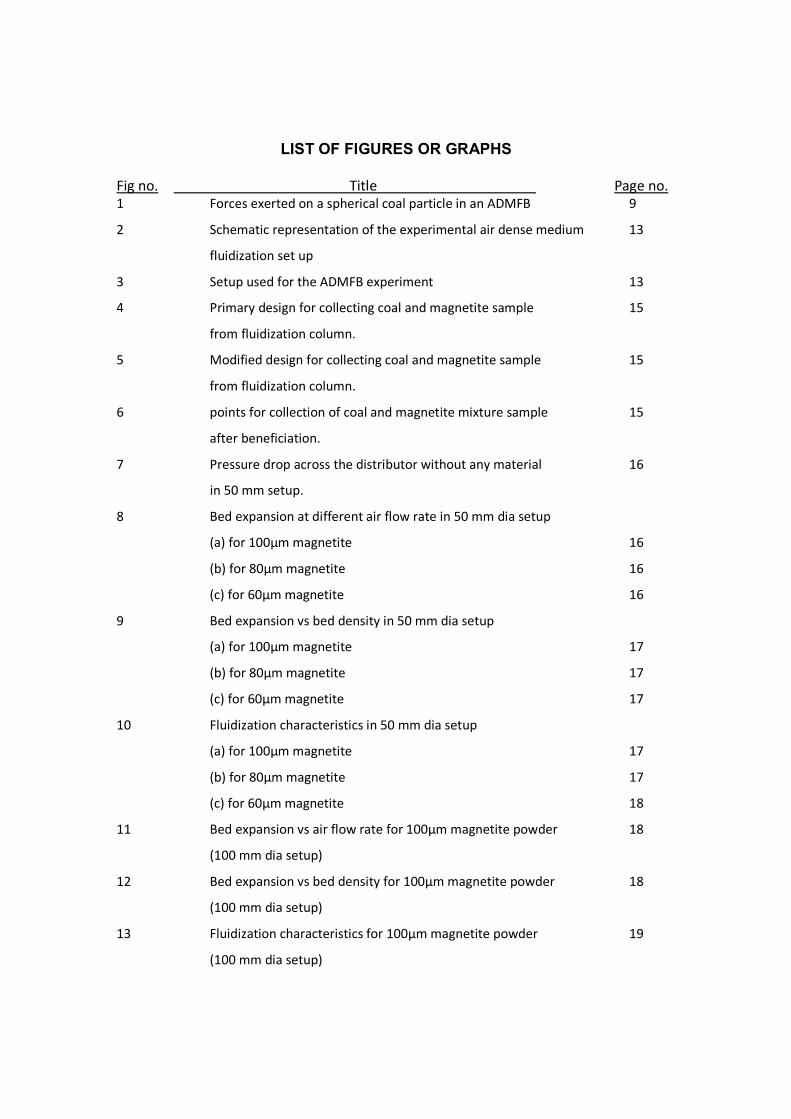
LIST OF FIGURES OR GRAPHS
Fig no. Title Page no.
1 Forces exerted on a spherical coal particle in an ADMFB 9
2 Schematic representation of the experimental air dense medium 13
fluidization set up
3 Setup used for the ADMFB experiment 13
4 Primary design for collecting coal and magnetite sample 15
from fluidization column.
5 Modified design for collecting coal and magnetite sample 15
from fluidization column.
6 points for collection of coal and magnetite mixture sample 15
after beneficiation.
7 Pressure drop across the distributor without any material 16
in 50 mm setup.
8 Bed expansion at different air flow rate in 50 mm dia setup
(a) for 100µm magnetite 16
(b) for 80µm magnetite 16
(c) for 60µm magnetite 16
9 Bed expansion vs bed density in 50 mm dia setup
(a) for 100µm magnetite 17
(b) for 80µm magnetite 17
(c) for 60µm magnetite 17
10 Fluidization characteristics in 50 mm dia setup
(a) for 100µm magnetite 17
(b) for 80µm magnetite 17
(c) for 60µm magnetite 18
11 Bed expansion vs air flow rate for 100µm magnetite powder 18
(100 mm dia setup)
12 Bed expansion vs bed density for 100µm magnetite powder 18
(100 mm dia setup)
13 Fluidization characteristics for 100µm magnetite powder 19
(100 mm dia setup)

14 ln E vs ln (Wc/Wm) 22
15 ln E vs ln (dpc/dpm) 22
16 ln E vs ln (dpc/Dt) 22
17 ln E vs ln (Gf-Gmf)/Gmf) 22
18 ln E vs ln (product) 23
19 comparison plot between experimental and calculated enrichment 24
LIST OF TABLES
Table no. _____ _ Title Page no.
1 Coal reserves in India (as on 1.1.2007) in billion tonnes 2
(data from Coal India Ltd)
2 Cost comparison of dry beneficiation processes 4
3 Technical Specification of filter cloth 12
4 Bed height vs air flow rate for varying quantities of 100µm 14
magnetite powder in 50 mm setup.
5 Bed expansion vs bed density for varying quantities 14
of 100µm magnetite powder in 50 mm setup.
6 Scope of experiment 15
7 Ash content of beneficiated coal (Abc) 20
8 Enrichment of coal after dry beneficiation in ADMFB 21
9 Data used for plotting ln E vs ln product 23

1
ABSTRACT
In this project, dry beneficiation of high ash non-coking coal has been conducted by air
dense medium fluidized bed. For dry separation, creating and sustaining the air dense
medium is a complex process which requires intensive investigation. The dynamic
stability of the bed which plays an important role in the sharpness of the separation has
also been studied. Based on experimental data, four dimensionless groups i.e. Froude
number, Reynolds number, ratio of density of fluid and solid and aspect ratio of the
system are used to characterize the s tabi l i t y and quality of fluidization. The above
stabilized bed is used to beneficiate coarse coal of -10 +0.1 mm size. The quality of
separation is judged by ash analysis of the beneficiated coal samples collected from
specified heights of the bed. Enrichment is represented as a function of different
operating parameters represented by four dimensionless groups obtained from
dimensional analysis approach. The values of enrichment calculated with the developed
correlation have been tested which agrees fairly well with the experimental values of
enrichment.
Keywords: Air dense medium fluidized bed, dry beneficiation of coal, Dynamic stability
of bed, Coal enrichment.

2
1. SIGNIFICANCE OF THE PROJECT
Beneficiation of non-coking coals in India was not given due importance till last
decade due to its low value or not being able to meet the cost of the process. About 73%
of the non-coking coal is used by the thermal power plants containing high ash
ranging from 40-50%. Recently, the Ministry of Environment and forest, govt. of India
has made a regulation to use the coal having ash less than 34% for the thermal plants
situated 1000 kms away from pit head or close to the urban/sensitive/critical area. These
categories of power plants in India are around 60% of total power plants. In addition
there is high demand for low ash content coal for sponge iron and blast furnace process.
In view of this it is required to reduce the ash content in present Indian non-coking coals
by any suitable beneficiation techniques so that the demand from steel plants (blast
furnace operation) , sponge iron and power plants can be met.
Table-1 COAL RESERVES IN INDIA (as on 1.1.2007) in billion tonnes (data from Coal India Ltd)
TOTAL
RESERVE
PROVED
RESERVE
INDICATED
RESERVE
INFERRED
RESERVE
COKING 32 17 13 2
NON-COKING 255 98 119 36
TOTAL 287 115 132 40
Due to the huge reserves of non-coking coal in India, in near future the dry beneficiation
technology associated with such non-coking coal is gradually going to gain importance.
1.1 WHY DRY BENEFICIATION
Dry coal beneficiation has constantly lost its importance vis-à-vis hydraulic
beneficiation during the last five decades, primarily because of the sharper separations
achievable with the modern hydraulic beneficiation technologies, such as gravity
separation and flotation for reduction of ash materials. Nevertheless, there are certain
inherent advantages of dry separation methods which would give them advantages in
the competitive market place to increase their thermal efficiency vis-à-vis hydraulic
processes. These advantages are

3
� A dry product, resulting in a higher calorific value per ton.
� The water source problem is acute in semi-arid areas. Hydraulic
processing of coal requires large quantity of water .Water is consumed as
product moisture, tailings disposal and evaporation.
� Waste generated from hydraulic process after maximizing the recycle the
water is unsuitable for disposal to water resources, because it contains
good amount of waste solids fines, which causes the pollution of water
bodies. Dry processes avoid the problems associated with treatment and
storage of process waste water.
� The fines generated in dry processing are suitable for ideal fuel for
fluidized bed combustor.
Water demand and pollution have opened up scope of research in the
development of the process for dry cleaning of coal. Significant developmental work in
dry beneficiation of coal is in progress in Canada, China and India.
There are different types of dry cleaning processes for coal beneficiation. Hand
picking of gangue minerals or shale in coarse size is one of the simplest, oldest and
labour intensive techniques of dry cleaning processes. The other dry cleaning techniques
are mechanical methods (screening, classifier, gravity concentrations, heavy media
separation etc.), magnetic separation, electrostatic separation, etc. These processes
depend on the differences in physical properties between coal and gangue minerals such
as density, size, shape, lusterness, magnetic conductivity, electric conductivity,
radioactivity etc. These methods have both advantages and disadvantages. Air dense
medium fluidized bed separation is one of the dry beneficiation processes that would
offer benefits compared to other dry beneficiation processes .The results of economic
evaluation for different processes is given in Table-2. The factor used to assess the main
processes under consideration is the cost per heat unit delivered to the power station. This
factor takes into account the benefit of reduced transport costs due to lower moisture
product.

4
Table-2 Cost comparison of dry beneficiation processes
2. HISTORY AND DEVELOPMENTS
Major efforts have been made in China for developing high efficiency dry coal
beneficiation methods. A dry beneficiation technology with air dense medium fluidized
bed separation has been under development by Mineral Processing Research Centre of
China University of Mining and Technology (CMUT), since 1984 by Q.Chen & Yufen
Yang.
The first dry coal beneficiation plant in the world with air dense medium fluidized bed
has been established by CUMT for beneficiation of -50 +6 mm size coal. The first
commercial sized dense medium fluidized bed separator with 7,00,000 TPA of –50+6
mm coal size had been operational since 1994 in Heiongjiang province of China.
It is claimed that high separation efficiency Ep value in the range of 0.05 to 0.07 is
achievable for the coal in the range of size –50+6 mm.
Two kinds of dense medium were used for the system like
� magnetic pearl for low density medium.
� fine magnetite powder for high density medium.
In some cases fine coal powder have been added to the magnetite medium for creating a
stable fluidizing bed.
Process Product
quality,
Kcal/kg
Yield,
%
Process operating
cost,
$/t
Cost delivered to
power station, $/Kcal
Conventional 5947.11 84.2 1.79 1.94
Rare Earth Magnetic
Separator
6281.5 68.4 1.55 2.16
Air Dense Medium Fluidized
Bed Separator
6281.5 80.6 1.91 1.91
(minimum)
Electrostatic Separator at
Mine
6639.75 59.9 5.01 2.65
Electrostatic Separator at
Power Station
6639.75 59.9 1.42 2.51
Air Table 6281.5 71.4 1.78 2.12

5
An air dense medium fluidized bed separator was designed and tested at Institute of
Minerals and Material Testing lab, (CSIR) Bhubaneswar, India in 2003 for beneficiation
of high ash Indian non-coking coal in the size range of -25+6 mm. The overall dimension
of the unit is 1507 mm x1022 mm x 130 mm width. The capacity of the unit is 600 kg/ hr
using high ash Indian coal. The ash percentage of feed coal is around 40%. The
characteristics of this type coal is totally different in comparison with other coal. The
near gravity material (NGM) is very high (15-20%). At the optimum condition, the ash
percentage of the feed could be reduced from 40 to 34% with 70% yield of product.
3. AIR DENSE MEDIUM FLUIDIZED BED BENEFICIATION
(SEPARATION) PROCESS--(ADMFB PROCESS)
The air dense medium separation uses a dense fluidized medium of air and fine
magnetite particles for beneficiation of any material. By means of a two phase gas-
solid pseudo-fluid separating medium, the light and heavy particles stratify in the
fluidized bed according to their individual densities. The bed density is more or less same
throughout fluidizing region. As the bed density of medium is presumed to be equal to
the separating density and the distribution of pressure in fluidized bed is the same as in
the static fluid, the motion of particles in the bed has been considered to explain the
mechanism of the beneficiation process.
3.1 PRINCIPLE OF AIR DENSE MEDIUM FLUIDIZED BED SEPARATOR
It is known that the general beds of particles fluidized by liquids behave very differently
from those fluidized by gases. In case of fluidized by liquid, it almost behaves
homogeneous manner with increasing liquid flow rate, whereas gas beds are
characterized by existence of bubbles. When fine powder is fluidized by gases, the bed
expands homogeneously up to a certain point over a range of gas velocity extending well
beyond minimum fluidization at which bubbles start to appear. The void fraction of the
dense phase is greater than at incipient fluidization where the velocity of the gas

6
increases, then the homogeneous or particulate system transfers to heterogeneous or
aggregate fluidization.
It has been reported that the addition of fines in a bed of small particles improves the
quality of fluidization by increasing the minimum bubbling velocity and the extent of
particulate expansion. Between minimum fluidization and minimum bubbling velocity,
fluidized bed of fine powder can exhibit particulate expansion to a large extent.
The current stage of progress in establishing theoretical criteria for the transition from
Particulate to aggregate fluidization has been reported by different mathematical forms 2,
3, 4, 5 & 6. An attempt was made in the present investigation on the stability of fluidized
bed using magnetite fine powder by air in dense medium fluidized bed separator under
particulate behaviour. The concept of this has been utilized later for beneficiation of non-
coking coal in dry process.
3.2 MATHEMATICAL EQUATIONS FOR CHECKING DYNAMIC STABILITY
OF ADMFB
A bed of particles resting on a distributor for a uniform up-flow of gas is considered. The
onset of fluidization occurs when the drag force by upward moving gas is equal to the
weight of the particles. It can be expressed mathematically as;
(Pressure drop across bed) (Cross sectional area of the bed) =
(Volume of the bed) (Fraction consisting of solids) (specific weight of solid)
( ) ( )
−−=×∆
c
gsmfmfttg
gLAAp ρρε1 (1)
The superficial velocity at the minimum fluidizing condition
( )mf
smfgsp
mf
gdU
ε
φε
µ
ρρ
−
−=
1150
232
,Rep,mf <20 (2)
For fine particles, the values recommended by Wen et al4, gives
( )[ ] 7.330408.033.7 Re5.02
mfp, −+= Ar (3)
7
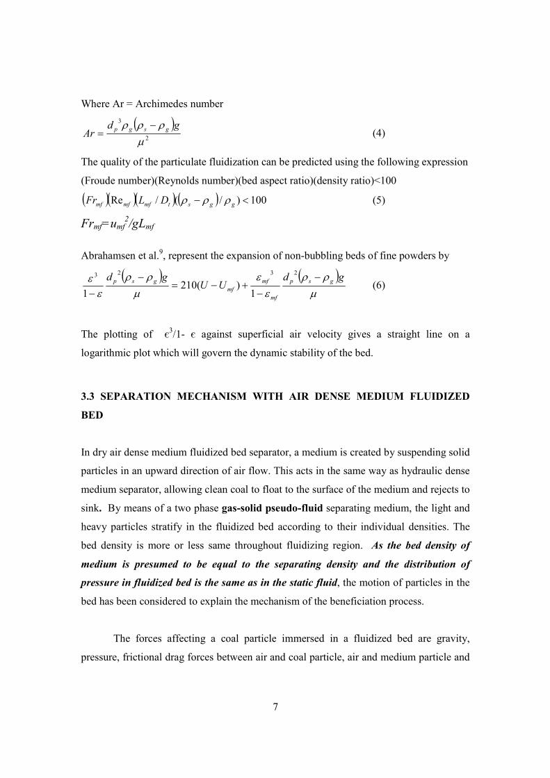
Where Ar = Archimedes number
( )2
3
µ
ρρρ gdAr
gsgp −= (4)
The quality of the particulate fluidization can be predicted using the following expression
(Froude number)(Reynolds number)(bed aspect ratio)(density ratio)<100
( )( )( ) ( ) 100)/(/Re <− ggstmfmfmf DLFr ρρρ (5)
Frmf=umf2/gLmf
Abrahamsen et al.9, represent the expansion of non-bubbling beds of fine powders by
( ) ( )µ
ρρ
ε
ε
µ
ρρ
εε gd
UUgd gsp
mf
mf
mf
gsp −
−+−=
−
−
2323
1)(210
1 (6)
The plotting of є3/1- є against superficial air velocity gives a straight line on a
logarithmic plot which will govern the dynamic stability of the bed.
3.3 SEPARATION MECHANISM WITH AIR DENSE MEDIUM FLUIDIZED
BED
In dry air dense medium fluidized bed separator, a medium is created by suspending solid
particles in an upward direction of air flow. This acts in the same way as hydraulic dense
medium separator, allowing clean coal to float to the surface of the medium and rejects to
sink. By means of a two phase gas-solid pseudo-fluid separating medium, the light and
heavy particles stratify in the fluidized bed according to their individual densities. The
bed density is more or less same throughout fluidizing region. As the bed density of
medium is presumed to be equal to the separating density and the distribution of
pressure in fluidized bed is the same as in the static fluid, the motion of particles in the
bed has been considered to explain the mechanism of the beneficiation process.
The forces affecting a coal particle immersed in a fluidized bed are gravity,
pressure, frictional drag forces between air and coal particle, air and medium particle and

8
medium and coal particle. It is the fluid like characteristics of the air dense medium
fluidized bed that separates the heavy and light particles. Some of the characteristics of
the bed are:
a) The air flow expands the bed surface,
b) The pressure drop between two points in the bed is almost equal to the difference
between the hydrostatic heads of same points,
ρ)( 2121 hhPPP −=−=∆ (7)
c) The bed demonstrates pseudo fluid flow characteristics.
d) Particles with relative density less than the bed density float to the top surface of
the bed while particles denser than the bed density sink towards the bottom of the
system, hence,
21 ρρρ << (8)
Where
ρ = density of bed
1ρ = density of light particle
2ρ = density of sink particle
Pseudo fluid characteristics in an air dense medium fluidized bed separator form a stable
and uniform gas–solid suspension with a certain bulk density in which light particles float
and heavy particles sink in the suspension medium.
The average density of the bed is bρ given by
ρb = (1-є)ρs + єρa= W/(LAg) (9)
Where,
ε = porosity of bed, %
sρ = density of the medium, kg/m3
aρ = density of air, kg/m3
W = total weight of the medium, kg
L = depth of the bed, m
A = cross section area of the fluidized system, m2
g = acceleration due to gravity, m/s2

9
Archimedes principle is generally referred to explain the mechanism of separation of coal
particles in the ADMFBS. But Archimedes principle can not explain the actual
experimental results, in which a small amount of light and heavy products are misplaced
during the separation process. Therefore, motion of the medium solids should be
considered to study the mechanism of separation in ADMFBS.
Compressed air
Fig. 1 Forces exerted on a spherical coal particle in an ADMFB
Therefore, making the force balance on the coal particle
sdgdbcc FFFgadG ++=+= )()6/(3ρπ (10)
Where,
=G gravitational force on coal particle, Newton
bF = effective buoyancy force exerted on the coal particle, Newton
gdF = friction drag force of gas exerted on the coal particle, Newton
sdF = drag force of air dense medium exerted on the coal particle, Newton
cρ = density of the coal particle, kg/m3
cd = equivalent diameter of the coal particle, m
a = acceleration of the coal particle, m/s2
g = gravitational acceleration , m/s2
µ = viscosity of medium, kg/m.s

10
The axial pressure distribution of fluidized bed can be expressed as
[ ] ggdxdp bas ρερρε =+−=− )1(/ (11)
Where,
bρ = density of bed, kg/m3
aρ = density of air, kg/m3
sρ = density of medium solids, kg/m3
ε = void fraction in the bed, %
The effective buoyancy force is
gdF csb
3)6/( ρπ= (12)
The general drag formula of fluid, sdF can be expressed as
rrcbsd UUdCF 2)6/( ρπ= (13)
Where,
C = drag co-efficient,
rU = relative velocity between coal particle and dense medium particles, m/s
As the diameter of a coal particle is much larger than that of the medium solid, the
friction drag force of the gas exerted on coal particle can be neglected.
The equation on simplification becomes
Acceleration, a = rr
cc
b
c
cb UUd
Cg
ρρ
ρρρ
+−
)( (14)
Let terminal velocity b
cbct
C
gdU
ρρρ )( −
= (15)
tU is the terminal velocity of coal particle in a fluidized bed when there is no relative
motion between the coal particle and the medium .

11
When rU is 0 i.e., there is no relative velocity between coal particle and fluidizing
medium, acceleration ccb ga ρρρ /)( −= the coal particles can be perfectly separated
according to the bed density,
and if cb ρρ = , rrccb UUdCa )/(ρρ= .
The position of coal particles in the bed depends on the relative velocity between the
coal particle and medium solids.
Separation efficiency is generally decided by the motion of the coal particles (i.e.,
misplacing effect of viscosity) and the velocity of medium solids (misplacing effect of
motion). At too low gas velocity the activity of medium solids is weak, which results in a
higher misplacing effect of viscosity.
Moreover, when the medium of solids are not well dispersed and gas can not be
uniformly distributed in the bed, the misplacing effect of motion is also larger in some
areas of bed. At too high gas velocity, back mixing of the medium solids caused by gas
bubbles is enhanced and the misplacing effect of motion will also be intensified. With
decrease of coal size, the specific surface increases and the terminal velocity of coal
particle decreases, resulting in the increase of ratio of drag to gravity exerted on the coal
particle and the increase of the misplacing effect of both viscosity and motion. Therefore,
the gas velocity of fluidization should be chosen according to the optimal velocity for the
separation of feed stock with minimum size.

12
4. MATERIALS AND UTILITIES
4.1 Material :
• The magnetite powder was collected from UCIL, Jaduguda. The true density of
the magnetite powder is 4.7 gm/cc .
• The coal used is taken from Mahanadi coal fields ltd, Ib Valley, Brajrajnagar. The
proximate analysis of the coal sample gives 43.9% ash content.
4.2 Utilities :
• The filter cloths were used as air distributor supplied by M/s Weaverbird Fabrics,
Nagpur and M/s Popat Brothers, Mumbai.
Table-3 : Technical Specification of filter cloth
• Here we are checking PL-2510, 1405, 2525, 2620. Among all the above PL-2511
is the best distributor but as it is not available, so we’ll use the next better one i.e.
2620.
• Compressor with air accumulator connected through silica gel tower.
• Rotameter (air) 0-100 lpm range
• Manometer 2 nos.(Hg and CCl4)
• A strong magnet of wide field for separating coal and magnetite particles.

13
5. EXPERIMENTAL WORK
5.1 EXPERIMENTAL SET UP
The experimental apparatus used in this study consists of three main parts; the air supply,
beneficiation apparatus and the pressure measurement of the bed. Two different set ups
were fabricated using perspex tube having diameter 50 and l00mm with height of 1250
and 1400 mm respectively. The air flow rate was measured using rotameter with range of
0-100 litre/minute. The filter cloths were used as air distributor. The pressure drop across
the distributor was measured with a manometer between one tapping placed on plenum
chamber and other just above the air distributor.
Fig-2 Schematic representation of the experimental
air dense medium fluidization set up
Fig-3 Setup used for the ADMFB experiment
5.2 EXPERIMENTAL PROCEDURE
5.2.1 FOR CHECKING THE BED STABILITY
Different filter cloths were used as distributor in 50 mm set up. Based on the bed
expansion and onset of bubbling, the 2620 filter cloth was used as air distributor for
further study. The compressed air was used in the system without any magnetite powder
to determine the pressure drop across the distributor only in 50 mm set up. Then the dried
magnetite powder was used to study the bed expansion at different air flow rate. The

14
quantity of magnetite powder was varied in the succesive experiments(refer to sample
tables: 4 and 5 and corresponding figures 8(a) and 9(a). The expansion of the bed was
studied at different air flow rate till the minimum bubbling starts in the bed.
Then same procedure was followed for 100 mm setup. The density of bed at different air
flow rates and corresponding voidage were determined by using the measuring
parameters of height of the expansion bed, true density of the solid and weight of the
sample.
Table-4 Bed height vs air flow rate for varying quantities of 100µm magnetite powder in 50 mm setup.
Height of bed, cm
air flow rate, lpm
200 gm of magnetite
300 gm of magnetite
400 gm of magnetite
500 gm of magnetite
0 6 9 12 15
5 7 10.5 13 17
10 8 11.5 15 19
15 9 13 16 20.5
20 10 14 18 23
25 10.5 15.5 19 24
30 11 16 20 25
40 13 18 24 29
50 14 18.5 26 30
Table-5 Bed expansion vs bed density for varying quantities of 100µm magnetite powder in 50 mm setup.
200 gm of magnetite 300 gm of magnetite 400 gm of magnetite 500 gm of magnetite air flow rate, lpm
Bed expansion
cm
Bed density gm/cc
Bed expansion
cm
Bed density gm/cc
Bed expansion
cm
Bed density gm/cc
Bed expansion
cm
Bed density gm/cc
0 0 1.698 0 1.698 0 1.698 0 1.698
5 1 1.456 1.5 1.4558 1 1.568 2 1.572
10 2 1.274 2.5 1.329 3 1.359 4 1.341
15 3 1.132 4 1.176 4 1.274 5.5 1.243
20 4 1.019 5 1.092 6 1.132 8 1.108
25 4.5 0.970 6.5 0.986 7 1.073 9 1.061
30 5 0.926 7 0.955 8 1.019 10 1.019
40 7 0.784 9 0.849 12 0.849 14 0.878
50 8 0.728 9.5 0.826 14 0.784 15 0.849
5.2.2 FOR DRY BENEFICIATION OF COARSE HIGH ASH COAL
After a uniform and stable ADMFB is formed, the coal of given size was put into the
fluidized bed. After 20 minutes, the air supply was cut off and bed samples were taken
from four equidistant bed heights (s1, s2, s3, s4) (Fig-6) using a vaccum pump. After
separation of magnetite, the ash of the coal samples from four equidistant bed heights

15
were analyzed by taking one gm of coal sample in a open silica crucible and heating in
muffle furnace at temp 750±15ºC for 1and ½ hrs. This was repeated with varying the air
flow rate and the sizes and amount of coal and magnetite. The scope of the experiment is
presented in table-6.
Table-6 SCOPE OF EXPERIMENT
dpc dpm Wc Wm Air flow rate Dt
1 mm 100µm 150 gm 100 gm 20 lpm 50 mm
5 mm 80µm 175 gm 100 gm 25 lpm 100 mm
10 mm 60µm 200 gm 100 gm 30 lpm
45µm 225 gm 100 gm 35 lpm
5.2.3 SAMPLE COLLECTION PROCEDURE
Fig-4 Primary design for collecting coal and
magnetite sample from fluidization column.
Fig-5 Modified design for collecting coal and
magnetite sample from fluidization column.
In the primary design (Fig-4) while collecting the
sample, a significant amount of fines entered into
the suction line connected to the vaccum pump
resulting chocking of the pump. So to rectify it,
collection design was modified (as shown in Fig-5)
so that the fines instead of entering into the suction
line got arrested over the cotton packing.
Fig-6 points for collection of coal and magnetite
mixture sample after beneficiation.
16
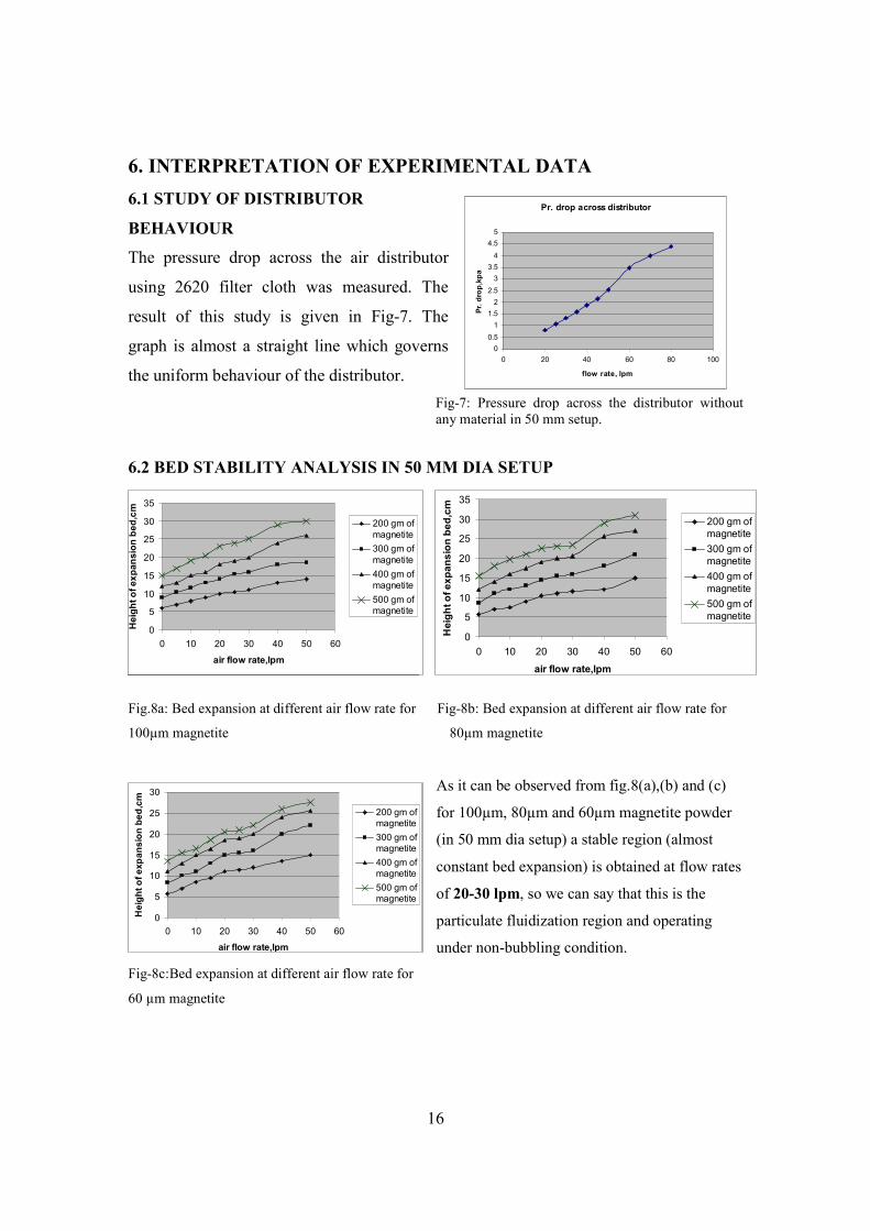
6. INTERPRETATION OF EXPERIMENTAL DATA
6.1 STUDY OF DISTRIBUTOR
BEHAVIOUR
The pressure drop across the air distributor
using 2620 filter cloth was measured. The
result of this study is given in Fig-7. The
graph is almost a straight line which governs
the uniform behaviour of the distributor.
Fig-7: Pressure drop across the distributor without
any material in 50 mm setup.
6.2 BED STABILITY ANALYSIS IN 50 MM DIA SETUP
Fig.8a: Bed expansion at different air flow rate for Fig-8b: Bed expansion at different air flow rate for
100µm magnetite 80µm magnetite
As it can be observed from fig.8(a),(b) and (c)
for 100µm, 80µm and 60µm magnetite powder
(in 50 mm dia setup) a stable region (almost
constant bed expansion) is obtained at flow rates
of 20-30 lpm, so we can say that this is the
particulate fluidization region and operating
under non-bubbling condition.
Fig-8c:Bed expansion at different air flow rate for
60 µm magnetite
0
5
10
15
20
25
30
35
0 10 20 30 40 50 60
air flow rate,lpm
Height of expansion bed,cm
200 gm of
magnetite
300 gm of
magnetite
400 gm of
magnetite
500 gm ofmagnetite
0
5
10
15
20
25
30
35
0 10 20 30 40 50 60
air flow rate,lpm
Height of expansion bed,cm
200 gm of
magnetite
300 gm of
magnetite
400 gm of
magnetite
500 gm of
magnetite
Pr. drop across distributor
0
0.5
1
1.5
2
2.5
3
3.5
4
4.5
5
0 20 40 60 80 100
flow rate, lpm
Pr. drop,kpa
0
5
10
15
20
25
30
0 10 20 30 40 50 60
air flow rate,lpm
Height of expansion bed,cm
200 gm of
magnetite
300 gm of
magnetite
400 gm of
magnetite
500 gm of
magnetite

17
Fig-9(a) Bed expansion versus bed density for Fig-9(b) Bed expansion versus bed density for
100µm magnetite 80µm magnetite
Further for 100µm magnetite, more
uniform curves (straight lines) are
obtained when bed expansion is plotted
against bed density (fig.9(a)). So 100µm
magnetite is selected. It shows that the
bed expansion is linear at different
quantities of magnetite powder, hence
the system is in non-bubbling condition.
Fig-9(c) Bed expansion versus bed density for
60µm magnetite
Fig-10(a)Fluidization characteristics for 100µm Fig-10(b) Fluidization characteristics for 80µm
magnetite in 50 mm dia setup magnetite in 50 mm setup
60 µm
0.60.70.80.91
1.11.21.31.41.51.61.71.81.92
-2 0 2 4 6 8 10 12 14 16
bed expansion,cm
bed density,gm/cc
500 gm
400 gm
300 gm
200 gm
Linear
(500 gm)Linear
(400 gm)Linear
(300 gm)Linear
(200 gm)
for 100 µm
-8
-7
-6
-5
-4
-3
-2
-1
0
1 1.5 2 2.5 3 3.5 4
ln U
ln(є
3/1-є)
200 gm
300 gm
400 gm
500 gm
Linear (200
gm)
Linear (300
gm)
Linear (400
gm)
Linear (500
gm)
for 80 µm
-7
-6
-5
-4
-3
-2
-1
0
1 1.5 2 2.5 3 3.5 4
ln U
ln(є
3/1-є)
200gm
300gm
400gm
500gm
Linear
(200gm)Linear
(300gm)Linear
(400gm)Linear
(500gm)
100 µm
0.7
0.8
0.9
1
1.1
1.2
1.3
1.4
1.5
1.6
1.7
1.8
-2 0 2 4 6 8 10 12 14 16
bed expansion,cm
bed density,gm/cc
500 gm
400 gm
300 gm
200 gm
Linear
(500 gm)Linear
(400 gm)Linear
(300 gm)Linear
(200 gm)
80 µm
0.6
0.7
0.8
0.9
1
1.1
1.2
1.3
1.4
1.5
1.6
1.7
1.8
1.9
-2 0 2 4 6 8 10 12 14 16 18
bed expansion,cm
bed density,gm/cc
500 gm
400 gm
300 gm
200 gm
Linear
(500 gm)Linear
(400 gm)Linear
(300 gm)Linear
(200 gm)

18
Again the characteristics of the
fluidized bed was examined using
equation (6) and the plotting of є3/1- є
against superficial air velocity gives a
straight line on a logarithmic plot. The
results are given in Fig-10(a), (b) &
(c).For 100µm magnetite, the
converging trend indicates that the Fig-
10(c) Fluidization characteristics for 60µm system operates in non-bubbling
magnetite in 50 mm dia setup condition.
6.3 BED STABILITY ANALYSIS IN 100 MM DIA SETUP
To see the effect of diameter on bed stability and thereafter on beneficiation, the larger
dia (100 mm) fluidized bed was used for a mixture of coal and 100µm magnetite powder
in varying amounts.
Fig-11: Bed expansion vs air flow rate for
100µm magnetite powder (100 mm dia setup)
Fig-12: Bed expansion vs bed density for 100µm
magnetite powder (100 mm dia setup)
As it can be observed for 100 mm dia setup almost constant bed heights are obtained for
air flow rates in the range 25-50 lpm. Further for 100µm magnetite powder the bed
expansion vs bed density plot (Fig-12) and Fluidization characteristics plot (ln(є3/1- є) vs
ln U) (Fig-13) give satisfactory results.
60 µm
0.60.70.80.91
1.11.21.31.41.51.61.71.81.92
-2 0 2 4 6 8 10 12 14 16
bed expansion,cm
bed density,gm/cc
500 gm
400 gm
300 gm
200 gm
Linear
(500 gm)Linear
(400 gm)Linear
(300 gm)Linear
(200 gm)
magnetite in 100 mm dia setup
0.7
0.8
0.9
1
1.1
1.2
1.3
1.4
1.5
1.6
1.7
1.8
-1 0 1 2 3 4
bed expansion,cm
bed density,gm/cc
500 gm
400 gm
300 gm
200 gm
Linear
(500 gm)Linear
(400 gm)Linear
(300 gm)Linear
(200 gm)0
1
2
3
4
5
6
7
8
0 10 20 30 40 50 60 70
air flow rate,lpm
Height of expansion bed,cm
200 gm of
magnetite
300 gm of
magnetite
400 gm of
magnetite
500 gm of
magnetite

19
Fig-13: Fluidization characteristics for 100µm magnetite powder in 100 mm dia setup
Now let’s calculate the minimum fluidizing velocity for the 50 mm dia setup.
Wt. of magnetite=400 gm
Initial bed height Linitial=12.0 cm
Mean dia. dp=100µm=0.01cm
Air viscosity µ=0.00019 gm/cm.sec
Particle density ρs=4.7 gm/cc
Air density ρg=0.0012928 gm/cc
Dia of column Dt=5.0 cm
Bed height at minimum fluidization Lmf=16 cm
Lmf / Dt =16/5=3.2
(ρs - ρg)/ ρg =3634.52
Ar = Archimedes number =165.07
For fine particles, the values recommended by Wen et al;
=0.0998
εmf=( Lmf - Linitial)/ Linitial =0.25
As Rep,mf<20
Hence ,the superficial velocity at the minimum fluidizing condition,
= 0.336 cm/sec or 0.4 lpm
So we need to operate above this flow rate.
Froude number Frmf=umf2/gLmf= 7.19*10
-6
Fluidization characteristics for 100 µm magnetite
in 100 mm dia setup
-6
-5
-4
-3
-2
-1
0
0.5 1 1.5 2 2.5 3
ln U
ln(є
3/1-є)
200 gm
300 gm
400 gm
500 gm
Linear
(200 gm)Linear
(300 gm)
Linear
(400 gm)Linear
(500 gm)
( )2
3
µ
ρρρ gdAr
gsgp −=
( )[ ] 7.330408.033.7 Re5.02
mfp, −+= Ar
( )mf
smfgsp
mf
gdU
ε
φε
µ
ρρ
−
−=
1150
232

20
The quality of the particulate fluidization can be predicted.
=0.0083 <100
Hence well with in the particulate fluidization range.
Similarly the minimum fluidization velocity for the bed (coal + magnetite) was calculated
to be Umf =0.784 cm/sec =0.923 lpm and checked for particulate fluidization.
Air flow rate used=25 lpm i.e. around 30 times Umf.
6.4 COAL ENRICHMENT ANALYSIS
The various coal samples were taken by varying Wc/Wm, dpc/Dt, dpc/dpm and (Gf-
Gmf)/Gmf.
Table-7 Ash content of beneficiated coal (Abc) Initial ash content Ac=43.9 %
Ash content, Abc % Run
no
dpc
mm
dpm
µm
Wc
gm
Wm
gm
Air flow rate,
lpm
Column
dia,mm S1 S2 S3 S4
1 1 100 200 100 25 50 32.5 34.5 37.5 40
2 1 80 200 100 25 50 36 36.5 38 39
3 1 60 200 100 25 50 37 37 37.5 41
4 5 100 200 100 25 50 34.5 37 38.5 40
5 5 80 200 100 25 50 36.5 38 38 41
6 5 60 200 100 25 50 38 39 39.5 41.5
7 10 100 200 100 25 50 35 38.2 38.7 41.1
8 10 80 200 100 25 50 37 38.3 38.8 41.4
9 10 60 200 100 25 50 38 39 40.6 42
10 1 45 200 100 25 50 36.4 37.6 39.3 41
11 1 100 150 100 25 50 36 36.5 38.5 40.1
12 1 100 175 100 25 50 36 37.1 37.4 41.3
13 1 100 225 100 25 50 32.9 35.2 37.4 40
14 1 100 200 100 20 50 34.6 35.2 37.1 41.4
15 1 100 200 100 30 50 32 35.1 36.8 41
16 1 100 200 100 35 50 32.3 35 36.5 41
17 1 100 200 100 25 100 32.6 33.4 35.2 36
( )( )( )( )ggstmfmfmf DLFr ρρρ //Re −

21
The magnetite particles from the samples were separated by magnetic separation and the
coal samples were subjected to ash analysis. The ash content of the above coal samples
after dry beneficiation is given in Table-7 from which the percentage Enrichments were
calculated using equation (16).
E= (Ac-Abc)/Ac*100= (43.9- Abc)/43.9*100 (16)
Table-8 Enrichment of coal after dry beneficiation in ADMFB
Ash content, Abc % Enrichment, E % Run
no S1 S2 S3 S4 S1 S2 S3 S4
1 32.5 34.5 37.5 40 26 21.4 14.6 8.88
2 36 36.5 38 39 18 16.8 13.44 11.16
3 37 37 37.5 41 15.72 15.72 14.58 6.6
4 34.5 37 38.5 40 21.4 15.72 12.3 8.88
5 36.5 38 38 41 16.86 13.44 13.44 6.6
6 38 39 39.5 41.5 13.44 11.16 10.02 5.46
7 35 38.2 38.7 41.1 20.27 12.98 11.84 6.38
8 37 38.3 38.8 41.4 15.72 12.76 11.6 5.69
9 38 39 40.6 42 13.44 11.16 7.52 4.33
10 36.4 37.6 39.3 41 17.08 14.35 10.48 6.6
11 36 36.5 38.5 40.1 18 16.86 12.3 8.65
12 36 37.1 37.4 41.3 18 15.49 14.8 5.9
13 32.9 35.2 37.4 40 25.06 19.82 14.8 8.88
14 34.6 35.2 37.1 41.4 21.18 19.82 15.49 5.69
15 32 35.1 36.8 41 27.11 20.04 16.17 6.6
16 32.3 35 36.5 41 26.4 20.27 16.86 6.6
17 32.6 33.4 35.2 36 25.74 23.9 19.82 18
7. RESULTS AND DISCUSSIONS
7.1 DEVELOPMENT OF CORRELATION
Considering acceptable value of ash in the beneficiated samples as 36 %, the values of
Enrichment for the first two sample points in case of each of the runs have been used in
the development of correlation and its testing with the additional experimental points.

22
The enrichment of coal (E) can be expressed as a function of various system and
operating parameters as:
E= f( Wc , Wm, Dt, dpc, dpm, Gf, Gmf ) (17)
From Dimensional analysis approach , the above equation can be represented in terms of
dimensionless groups as
E=
nd
mf
mff
c
t
pc
b
pm
pc
a
m
c
G
GG
D
d
d
d
W
Wk
−
=k (product)
n (18)
Where a, b, c and d are the exponents of the individual groups calculated from log-log
plots of E vs. the groups. (Fig.14, 15, 16 and 17 respectively)
Fig.14: ln E vs ln (Wc/Wm) Fig.16: ln E vs ln (dpc/Dt)
Fig.15: ln E vs ln (dpc/dpm) Fig.17: ln E vs ln (Gf-Gmf)/Gmf)
y = 0.7997x + 2.4907
R2 = 0.4874
2.7
2.8
2.9
3
3.1
3.2
3.3
0.2 0.4 0.6 0.8 1
ln(Wc/Wm)
ln E
y = -0.1615x + 2.5308
R2 = 0.4673
2
2.2
2.4
2.6
2.8
3
3.2
3.4
-5 -4 -3 -2 -1 0
ln(dpc/Dt)
ln E
y = -0.4799x + 4.1695
R2 = 0.64
2
2.2
2.4
2.6
2.8
3
3.2
3.4
2 2.2 2.4 2.6 2.8 3 3.2
ln(dpc/dpm)
ln E
y = 0.3858x + 1.9336
R2 = 0.7208
3
3.1
3.2
3.3
3.4
3 3.1 3.2 3.3 3.4 3.5 3.6 3.7
ln((Gf-Gmf)/Gmf)
ln E

23
Values of the exponents obtained are a=0.800 b=-0.480 c= -0.162
d=0.386
The final correlation is obtained by plotting the product
−
−− 386.0162.048.08.0
mf
mff
t
pc
pm
pc
m
c
G
GG
D
d
d
d
W
W against E on a log-log plot (as shown in
fig.18) .The data which are used for plotting Fig-18 are given in Table-9.
So we get, k=7.715 n=0.8179
Fig.18: ln E vs ln (product)
Table-9 Data used for plotting ln E vs ln product
Wc/Wm dpc/dpm (Gf-Gmf)/Gmf dpc/Dt Eexpt
1.5 10 26.08 0.02 18
1.75 10 26.08 0.02 18
2 10 26.08 0.02 26
2.25 10 26.08 0.02 25.06
2 12.5 26.08 0.02 18
2 16.67 26.08 0.02 15.72
2 22.22 26.08 0.02 17.08
2 10 20.68 0.02 21.18
2 10 31.52 0.02 27.11
2 10 36.88 0.02 26.4
2 10 26.08 0.1 21.4
2 10 26.08 0.2 20.27
y = 0.8179x + 2.0432
R2 = 0.5835
2.7
2.8
2.9
3
3.1
3.2
3.3
3.4
0 0.5 1 1.5 2
ln (product)
ln E

24
Thus the final correlation obtained is:
E=
−
−− 3155.01321.03925.06541.0
715.7mf
mff
t
pc
pm
pc
m
c
G
GG
D
d
d
d
W
W (19)
Now, the rest experimental enrichment data (other than used for calculating the
correlation) were used to verify the above correlation.
The enrichment values calculated from the above correlation have been compared with
the experimental values of enrichment (fig.19) and fairly good agreement has been found.
Fig-19 Comparison plot between the experimental
and the calculated values of enrichment
7.2 DISCUSSION ON RESULTS AND CONCLUSION
It has been found that enrichment is a direct function of coal to magnetite and excess
velocity ratios. But both of the above variables Contribute to high bed pressure drop
marginally with the increase in power consumption. Enrichment is inversely proportional
to coal particle size as indicated by the negative exponent of the of the other two groups
but there is a limiting size from the operational convenience as fine coal particles will
create environmental problem and the beneficiated small-sized coal particles will have
limited downstream uses.
10
15
20
25
30
10 15 20 25 30
E, experimental
E,calulated
Standard deviation=9.915
Mean deviation=10.17

25
From the above considerations, coal and magnetite particles of sizes 1 mm and 100µm
respectively in the amount ratio 2:1 with 30 times the minimum fluidization velocity has
been found to be effective for enrichment in a 50 mm diameter fluidized bed reducing the
ash content of the coals of Mahanadi coal fields ltd, Ib Valley, Brajrajnagar from 43.9%
to nearly 36% on an average with 60 percent yield of product. The single test in a large
diameter (100 mm) fluidized bed also corroborates the above conclusion.
8. POTENTIAL APPLICATION OF THE PRESENT PROJECT
WORK
In view of appreciable beneficiation achieved with respect to the reduction of ash content
obtained in the present experimental studies and tested for a relatively larger size
equipment, there is an excellent potential for the application of this result for further
scale up in the pilot plant/semi-commercial and commercial unit for the ultimate use of
the presently-discarded high ash coal with dry beneficiation for various process
applications viz. thermal power plant, sponge iron unit and coke ovens.

26
9. NOTATIONS
Ac=ash content of coal before beneficiation, percentage
Abc=ash content of beneficiated coal, percentage
Ar = Archimedes number
( )2
3
µ
ρρρ gdAr
gsgp −= , dimensionless
At= Area of cross section of the fluidized bed, cm2
dp = particle diameter, cm
dpc= coal particle diameter, cm
dpm=magnetite particle diameter, cm
Dt = Diameter of the fluidization column, cm
E= Enrichment, percentage
Frmf= Fraud number at minimum fluidization
=umf2/gLmf , dimensionless
g =Acceleration due to gravity, cm/sec2
Gf=mass velocity of air at any flow rate, gm/cm2.sec
Gmf= mass velocity of air at minimum fluidization velocity, gm/cm2.sec
L = Bed height, cm
Lmf = Bed height at minimum fluidization, cm
Remf= Reynolds number at minimum fluidization
=(dp Umf ρg)/ µ , dimensionless
Umf= superficial velocity at minimum fluidization, cm/sec
Wc=Weight of coal taken, gms
Wm= Weight of magnetite taken, gms
єmf= Bed voidage at minimum fluidization
ρs= Particle density, gm/cc
ρg = air density, gm/cc
∆p = pressure drop across bed, bar
Φs= sphericity of particle
µ= Air viscocity, gm/cm.sec

27
10. REFERENCES
1. Zhenfu L. and Qingru C., Dry Beneficiation Technology of Coal with an Air Dense
Medium Fluidized Bed, International Journal of Mineral Processing 43: (2001) 147-175.
2. Luo, Z., Chen, Q., Zhao, Y.,. Dry beneficiation of coarse coal using an air dense
medium fluidized bed, Coal Preparation, 22, (2002) 57-64.
3. Luo, Z., Chen, Q. Zhao, Y., Tao, X., Fan, M., and Wei, L.,. Progress in dry coal
cleaning using air dense medium fluidized beds. Coal Preparation, 23, (2003) 13-20.
4. Wen C Y, and Yu Y H, AIChEJ, 12 (1966) 610-612.
5. IMMT, Bhubaneswar, 2003, Report No. T/MPT/436/Oct/2003. Dry beneficiation of
high ash non-coking coal using air dense medium fluidized bed separator.
6. Sahu, A.K., Biswal, S. K., Parida, A., Reddy, P.S.R., and Misra, V. N.,. A study of
dynamic stability of medium in fluidized bed separator. IIM Transactions (India), 56(1),
(2005) 103-107.
7. Dwari, R. K. and Rao, K. Hanumantha 'DRY BENEFICIATION OF COAL—A
REVIEW', Mineral Processing and Extractive Metallurgy Review,28:3, (2007) 177 –
234.
8. McCabe W L, Smith J C, Harriott P, “Unit Operations of Chemical Engineering”,
seventh edition, McGraw-Hill Higher Education (2005)177-188.
9. Abrahamsen A R, and Geldart D, Powder Technology, 26 (1980) 46.
10. Kunii D, and Levenspiel O, Fluidization Engineering 2nd Ed.’Chapter-3 (1991) 61-
94.