DrJ Research Report DRR 1303-04
19
For current information on this topic refer to Quick Guide: Cladding Connections to Wood Frame Walls with FPIS ci DrJ Research Report DRR 1303-04 Attachment of Exterior Wall Coverings through Foam Plastic Insulating Sheathing to Wood Wall Framing Foam Sheathing Committee (FSC) Members Code Compliance Process: Attachment of exterior wall coverings through Foam Plastic Insulating Sheathing (FPIS) to wood wall framing Issue Date: August 18, 2014 Revision Date: October 19, 2020
Transcript of DrJ Research Report DRR 1303-04

For current information on this topic refer to
Quick Guide: Cladding Connections to Wood Frame Walls with FPIS ci
DrJ Research Report
DRR 1303-04
Attachment of Exterior Wall Coverings
through Foam Plastic Insulating
Sheathing to Wood Wall Framing
Foam Sheathing Committee
(FSC) Members
Code Compliance Process:
Attachment of exterior wall
coverings through Foam Plastic
Insulating Sheathing (FPIS) to
wood wall framing
Issue Date:
August 18, 2014
Revision Date:
October 19, 2020

DRR 1303-04: ATTACHMENT OF EXTERIOR WALL COVERINGS THROUGH FOAM PLASTIC INSULATING SHEATHING TO WOOD WALL FRAMING
REVISION 10/19/2020 © 2021 DRJ ENGINEERING, LLC
PAGE 2 OF 19
REPORT HOLDER
INFORMATION:
Foam Sheathing Committee (FSC) Members
fsc.americanchemistry.com/Members
continuousinsulation.org
DIVISION: 07 00 00 - THERMAL AND MOISTURE PROTECTION
SECTION: 07 21 00 - Thermal Insulation
SECTION: 07 40 00 - Roofing and Siding Panels
SECTION: 07 46 00 - Siding
1 PRODUCT EVALUATED1
Attachment of exterior wall coverings through Foam Plastic Insulating Sheathing (FPIS) to wood wall framing
2 APPLICABLE CODES AND STANDARDS2,3
Codes
2.1.1 IBC—12, 15, 18: International Building Code®
2.1.2 IRC—12, 15, 18: International Residential Code®
Standards and Referenced Documents
2.2.1 ANSI/AWC NDS: National Design Specification (NDS) for Wood Construction
2.2.2 ASCE/SEI 7: Minimum Design Loads and Associated Criteria for Buildings and Other Structures
2.2.3 ASTM C1063: Standard Specification for Installation of Lathing and Furring to Receive Interior and Exterior
Portland Cement-Based Plaster
2.2.4 ASTM C1289: Standard Specification for Faced Rigid Cellular Polyisocyanurate Thermal Insulation Board
2.2.5 ASTM C578: Standard Specification for Rigid, Cellular Polystyrene Thermal Insulation
2.2.6 ASTM C847: Standard Specification for Metal Lath
2.2.7 ASTM F1667: Standard Specification for Driven Fasteners: Nails, Spikes, and Staples
2.2.8 SBCA ANSI/FS 100: Standard Requirements for Wind Pressure Resistance of Foam Plastic Insulating
Sheathing Used in Exterior Wall Covering Assemblies
3 EVALUATION SCOPE
1 Building codes require data from valid research reports be obtained from approved sources. Work of licensed registered design professionals (RDPs) meets the code requirements for
approval by the building official.
Building official approval of a licensed RDP is performed by verifying the RDP and/or their business entity complies with all professional engineering laws of the relevant jurisdiction. Therefore, the work of licensed RDPs is accepted by building officials, except when plan (i.e. peer) review finds an error with respect to a specific section of the code. Where this DRR is not approved, the building official responds in writing stating the reasons for disapproval.
For more information on any of these topics or our mission, product evaluation policies, product approval process, and engineering law, visit drjengineering.org or call us at 608-310-6748.
2 Unless otherwise noted, all references in this DRR are from the 2018 version of the codes and the standards referenced therein (e.g., ASCE 7, NDS, ASTM). This material, design, or
method of construction also complies with the 2000-2015 versions of the referenced codes and the standards referenced therein.
3 All terms defined in the applicable building codes are italicized.

DRR 1303-04: ATTACHMENT OF EXTERIOR WALL COVERINGS THROUGH FOAM PLASTIC INSULATING SHEATHING TO WOOD WALL FRAMING
REVISION 10/19/2020 © 2021 DRJ ENGINEERING, LLC
PAGE 3 OF 19
This research report examines the attachment of exterior wall coverings through FPIS, with thickness up to 4", to
wood wall studs.
This research report also provides a systematic approach for the design process of attaching exterior wall
coverings through FPIS to wood wall framing.
This evaluation and design methodology considers only the weight of the exterior covering on fasteners
cantilevered though the FPIS and into wall framing.
Wind pressure resistance of the exterior covering is outside the scope of this research report. Consult the
cladding manufacturer for cladding and attachment instructions for required wind pressure resistance. For wind
pressure resistance of FPIS, consult the FPIS manufacturer’s installation instructions and wind pressure
resistance data complying with ANSI/SBCA FS100.
3.4.1 The intent of this research report is not to reduce minimum fastener size, penetration, and spacing required to
resist wind loads. Where fastener requirements for wind load resistance are more stringent than those
included herein for the purpose of supporting cladding weight, they shall control the design.
Attachment of window flanges over FPIS is outside the scope of this research report. For this application see
DRR 1304-01.
Any code compliance issues not specifically addressed in this section are outside the scope of this DRR.
Any engineering evaluation conducted for this DRR was performed on the dates provided in this DRR and within
DrJ’s professional scope of work.
4 PRODUCT DESCRIPTION AND MATERIALS
FPIS products used in accordance with this research report shall comply with the following material standards:
4.1.1 Expanded polystyrene (EPS) manufactured in compliance with ASTM C578
4.1.2 Extruded polystyrene (XPS) manufactured in compliance with ASTM C578
4.1.3 Polyisocyanurate (Polyiso) manufactured in compliance with ASTM C1289
FPIS products used in accordance with this research report shall have a minimum compressive strength of 15 psi.
Where wind pressure resistance is required, FPIS products used in accordance with this research report shall
comply with SBCA ANSI/FS 100.
FPIS products are produced under proprietary manufacturing processes and are formed into rigid insulation
panels.
FPIS products are typically available in the following sizes:
4.5.1 Thicknesses range from ½" to 6".
4.5.2 The standard product width is 48".
4.5.3 Standard lengths include 96", 108", and 120".
Consult the manufacturer for the availability of a given product with non-standard width or length.
The following FPIS products meet the requirements of Section 4.1 and 4.2:
4.7.1 Atlas Roofing Corporation – Energy Shield®, Energy Shield® Pro, Energy Shield® Pro2, Energy Shield®
CGF, Energy Shield® CGF PRO, Stucco Shield®, ThermalStar® LCi 15, ThermalStar® LCi 25, ThermalStar®
One, ThermalStar® GX, and ThermalStar® XTR T&G
4.7.2 BASF Corporation – Neopor®
4.7.3 DuPont de Nemours, Inc. – Styrofoam™, Tuff-R™, Super Tuff-R™, Thermax™, Thermax™ (ci) Exterior,
Thermax™ Heavy Duty, Thermax™ Light Duty, Thermax™ White Finish, Thermax™ Metal Building Board,
and Isocast™ R Thermal
4.7.4 Hunter Panels – Xci Foil (Class A), Xci CG (Class A), Xci 286, Xci Ply (Class A), Xci Foil, Xci CG, Xci Ply, and
Xci NB
4.7.5 Kingspan Insulation, LLC – GreenGuard® Insulation Boards: CM, SL, SLX, and PGU

DRR 1303-04: ATTACHMENT OF EXTERIOR WALL COVERINGS THROUGH FOAM PLASTIC INSULATING SHEATHING TO WOOD WALL FRAMING
REVISION 10/19/2020 © 2021 DRJ ENGINEERING, LLC
PAGE 4 OF 19
4.7.6 Rmax – R-Matte® Plus-3, Durasheath®, Thermasheath®, Thermasheath®-SI, Thermasheath®-XP,
ECOMAXci® FR, ECOMAXci® FR White, TSX-8500, TSX-8510, ECOMAXci® Wall Solution, ECOMAXci®
Ply, ECOMAXci® FR Ply, and THERMABASEci™
5 APPLICATIONS
Design Procedure
5.1.1 Determine an appropriate cladding attachment requirement in accordance with Section 5.1 through 5.2.
5.1.2 Select one of the following methods of cladding attachment:
5.1.2.1 Direct attachment of cladding through FPIS to wall framing, Figure 1.
5.1.2.2 Furring attachment through FPIS to wall framing, Figure 2, whereby cladding is attached to furring in
accordance with the applicable building code and the cladding manufacturer’s installation instructions.
5.1.2.3 Direct attachment of cladding to qualifying wood structural panels, Figure 3.
5.1.2.3.1 Exterior wall coverings weighing not more than 3 psf are permitted to be fastened through FPIS up to
2 inches in thickness into wood structural panel sheathing without penetrating into the framing. The
attachment shall be in accordance with the manufacturer’s instructions and supported by a testing
report, or a product certification report, or shall be fastened in accordance with the IRC Section
R703.3.3 and Table R703.3.3.
(a) Cladding
(b1) Fastener (Foam to Stud)
(b2) Fastener (Cladding to Stud)
(d) FPIS
(e) Framing
(f) Cavity Insulation
(g) Wall Finish
FIGURE 1. PLAN VIEW – DIRECT CLADDING ATTACHMENT THROUGH FPIS
(a) Cladding
(b1) Fastener (Foam to Stud)
(b2) Fastener (Furring to Stud)
(b3) Fastener (Cladding to Furring)
(c) Wood Furring
(d) FPIS
(e) Framing
(f) Cavity Insulation
(g) Wall Finish
FIGURE 2. CLADDING ATTACHMENT THROUGH FURRING
DRR 1303-04: ATTACHMENT OF EXTERIOR WALL COVERINGS THROUGH FOAM PLASTIC INSULATING SHEATHING TO WOOD WALL FRAMING
REVISION 10/19/2020 © 2021 DRJ ENGINEERING, LLC
PAGE 5 OF 19
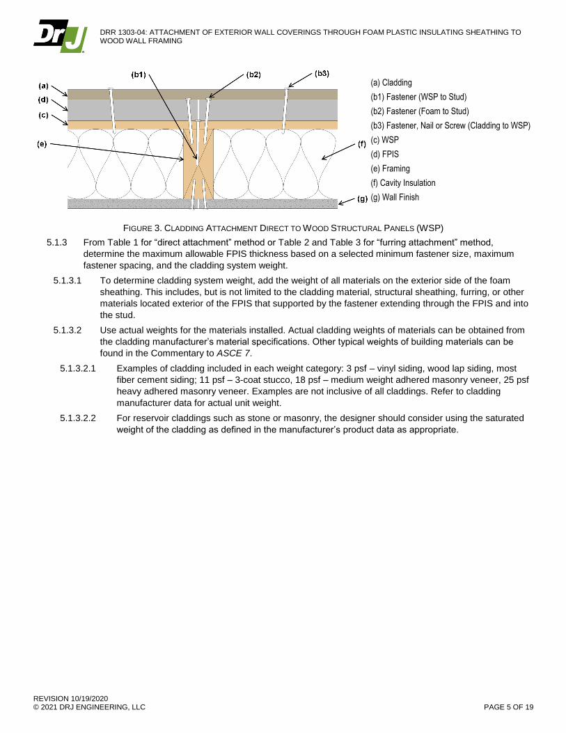
(a) Cladding
(b1) Fastener (WSP to Stud)
(b2) Fastener (Foam to Stud)
(b3) Fastener, Nail or Screw (Cladding to WSP)
(c) WSP
(d) FPIS
(e) Framing
(f) Cavity Insulation
(g) Wall Finish
FIGURE 3. CLADDING ATTACHMENT DIRECT TO WOOD STRUCTURAL PANELS (WSP)
5.1.3 From Table 1 for “direct attachment” method or Table 2 and Table 3 for “furring attachment” method,
determine the maximum allowable FPIS thickness based on a selected minimum fastener size, maximum
fastener spacing, and the cladding system weight.
5.1.3.1 To determine cladding system weight, add the weight of all materials on the exterior side of the foam
sheathing. This includes, but is not limited to the cladding material, structural sheathing, furring, or other
materials located exterior of the FPIS that supported by the fastener extending through the FPIS and into
the stud.
5.1.3.2 Use actual weights for the materials installed. Actual cladding weights of materials can be obtained from
the cladding manufacturer’s material specifications. Other typical weights of building materials can be
found in the Commentary to ASCE 7.
5.1.3.2.1 Examples of cladding included in each weight category: 3 psf – vinyl siding, wood lap siding, most
fiber cement siding; 11 psf – 3-coat stucco, 18 psf – medium weight adhered masonry veneer, 25 psf
heavy adhered masonry veneer. Examples are not inclusive of all claddings. Refer to cladding
manufacturer data for actual unit weight.
5.1.3.2.2 For reservoir claddings such as stone or masonry, the designer should consider using the saturated
weight of the cladding as defined in the manufacturer’s product data as appropriate.

DRR 1303-04: ATTACHMENT OF EXTERIOR WALL COVERINGS THROUGH FOAM PLASTIC INSULATING SHEATHING TO WOOD WALL FRAMING
REVISION 10/19/2020 © 2021 DRJ ENGINEERING, LLC
PAGE 6 OF 19
TABLE 1. SIDING MINIMUM FASTENING REQUIREMENTS FOR DIRECT CLADDING ATTACHMENT OVER FPIS TO SUPPORT CLADDING
SYSTEM WEIGHT
Framing Member
Siding Fastener Type &
Minimum Size
Siding Fastener Vertical Spacing
(in)
Maximum Thickness of FPIS (in)
16" o.c. Fastener Horizontal Spacing 24" o.c. Fastener Horizontal Spacing
Maximum Cladding Weight (psf)
3 11 18 25 3 11 18 25
Wood Framing
(minimum 1¼"
penetration)
0.113" diameter
nail
6 2.00 1.45 0.75 DR 2.00 0.85 DR DR
8 2.00 1.00 DR DR 2.00 0.55 DR DR
12 2.00 0.55 DR DR 1.85 DR DR DR
0.120" diameter
nail
6 3.00 1.70 0.90 0.55 3.00 1.05 0.50 DR
8 3.00 1.20 0.60 DR 3.00 0.70 DR DR
12 3.00 0.70 DR DR 2.15 DR DR DR
0.131" diameter
nail
6 4.00 2.15 1.20 0.75 4.00 1.35 0.70 DR
8 4.00 1.55 0.80 DR 4.00 0.90 DR DR
12 4.00 0.90 DR DR 2.70 0.50 DR DR
0.162" diameter
nail
6 4.00 3.55 2.05 1.40 4.00 2.25 1.25 0.80
8 4.00 2.55 1.45 0.95 4.00 1.60 0.85 0.50
12 4.00 1.60 0.85 0.50 4.00 0.95 DR DR
SI: 1 in = 25.4 mm, 1 psf = 0.0479 kN/m2
1. Tabulated requirements are based on wood framing of Spruce-Pine-Fir or any wood species with a specific gravity of 0.42 or greater in accordance with NDS
2. See Applied Building Technology Group (ABTG) Research Report 1503-02 for information on how the table values were derived.
3. Nail fasteners shall comply with ASTM F1667, except nail length shall be permitted to exceed ASTM F1667 standard lengths. Other approved fasteners of equivalent or greater diameter and bending strength shall be permitted.
4. For cladding system weights exceeding 25 psf with any thickness of foam sheathing, a design professional should be consulted.
5. Table 1 solutions are limited to 4" maximum thickness of foam sheathing. Design is required for thicknesses of foam sheathing greater than 4".
6. Foam sheathing shall have a minimum compressive strength of 15 psi in accordance with ASTM C578 or ASTM C1289.
7. Metal lath shall be minimum 2.5 lb/yd2 diamond mesh in accordance with ASTM C847. Metal lath lock washers on fasteners are highly recommended.
8. Vertical spacing of fasteners in metal lath shall not exceed 7" o.c., in accordance with ASTM C1063 and the Masonry Veneer Manufacturer Association (MVMA) Installation Guide except where an approved design is provided.
9. Where adhered masonry is used, it shall be installed in accordance with the MVMA Installation Guide or an approved design.
10. Linear interpolation between cladding weight categories is not permissible.
11. DR = Design Required

DRR 1303-04: ATTACHMENT OF EXTERIOR WALL COVERINGS THROUGH FOAM PLASTIC INSULATING SHEATHING TO WOOD WALL FRAMING
REVISION 10/19/2020 © 2021 DRJ ENGINEERING, LLC
PAGE 7 OF 19
TABLE 2. FURRING MINIMUM FASTENING REQUIREMENTS FOR APPLICATION OVER FPIS TO SUPPORT CLADDING SYSTEM WEIGHT
Furring Material
Framing Member
Fastener Type &
Minimum Size
Minimum Penetration
into Wall Framing (in)
Fastener Spacing
in Furring
(in)
Maximum Thickness of FPIS (in)
16" o.c. Furring 24" o.c. Furring
Maximum Cladding Weight (psf)
3 11 18 25 3 11 18 25
Minimum 1x3
Wood Furring
Minimum 2x Wood
Stud
Nail (0.120" shank; 0.271" head)
11/4
8 3.00 1.85 1.05 0.65 3.00 1.20 0.60 DR
12 3.00 1.20 0.60 DR 3.00 0.70 DR DR
16 3.00 0.80 DR DR 2.30 DR DR DR
Nail (0.131" shank; 0.281" head)
11/4
8 4.00 2.45 1.45 0.95 4.00 1.60 0.85 DR
12 4.00 1.60 0.85 DR 4.00 0.95 DR DR
16 4.00 1.10 DR DR 3.05 0.60 DR DR
0.162" diameter
nail 11/4
8 4.00 4.00 2.45 1.60 4.00 2.75 1.45 0.85
12 4.00 2.75 1.45 0.85 4.00 1.65 0.75 DR
16 4.00 1.90 0.95 DR 4.00 1.05 DR DR
#10 wood screw
1
12 4.00 2.30 1.20 0.70 4.00 1.40 0.60 DR
16 4.00 1.65 0.75 DR 4.00 0.90 DR DR
24 4.00 0.90 DR DR 2.85 DR DR DR
¼" lag screw
11/2
12 4.00 2.65 1.50 0.90 4.00 1.65 0.80 DR
16 4.00 1.95 0.95 0.50 4.00 1.10 DR DR
24 4.00 1.10 DR DR 3.25 0.50 DR DR
SI: 1 in = 25.4 mm, 1 psf = 0.0479 kN/m2
1. Table values are based on:
a. Minimum ¾" (19.1 mm) thick wood furring and wood studs of SPF or any softwood species with a specific gravity of 0.42 or greater per NDS
2. Nail fasteners shall comply with ASTM F1667, except nail length shall be permitted to exceed ASTM F1667 standard lengths. Wood screws and lag screws shall comply with NDS Appendix L and ANSI/ASME B18.6.1. Other approved fasteners of equivalent or greater diameter and bending strength shall be permitted.
3. Furring shall be spaced a maximum of 24" o.c. in a vertical or horizontal orientation.
a. In a vertical orientation, furring shall be located over wall studs and attached with the required fastener spacing.
b. Where placed horizontally, wood furring shall be preservative treated wood in accordance with IRC Section R317.1 or naturally durable wood and fasteners shall be corrosion resistant in accordance IRC Section R317.3.
c. Furring strips installed in a horizontal direction shall be fastened at each stud with a number of fasteners equivalent to that required by the fastener spacing. If the required nail spacing is 12" o.c. and the studs are 24" o.c., then two (2) nails would be required at each stud (24/12=2). In no case shall fasteners be spaced more than 24" (0.6 m) apart.
4. Lag screws shall be installed with a standard cut washer.
5. Lag screws and wood screws shall be pre-drilled in accordance with NDS.
6. A minimum 2x wood furring shall be used where the required siding fastener penetration into wood material exceeds ¾" (19.1 mm) and is not more than 1½" (38.1 mm), unless approved deformed shank siding nails or siding screws are used to provide equivalent withdrawal strength, allowing the siding connection to be made to a 1x wood furring.
7. For cladding system weights exceeding 25 psf with any thickness of foam sheathing, a design professional should be consulted.
8. Table 2 solutions are limited to 4" maximum thickness of foam sheathing. Design is required for thicknesses of foam sheathing greater than 4".
9. Foam sheathing shall have a minimum compressive strength of 15 psi, in accordance with ASTM C578 or ASTM C1289.
10. Linear interpolation between cladding weight categories is not permissible.
11. DR = Design Required

DRR 1303-04: ATTACHMENT OF EXTERIOR WALL COVERINGS THROUGH FOAM PLASTIC INSULATING SHEATHING TO WOOD WALL FRAMING
REVISION 10/19/2020 © 2021 DRJ ENGINEERING, LLC
PAGE 8 OF 19
TABLE 3. FURRING MINIMUM FASTENING REQUIREMENTS FOR APPLICATION OVER FOAM PLASTIC INSULATING SHEATHING TO
RESIST ALLOWABLE STRESS WIND PRESSURE
Furring Material
Framing Member
Fastener Type &
Minimum Size
Minimum Penetration into Wall Framing (in)
Fastener Spacing in Furring (in)
Allowable Wind Pressure Resistance of Furring Attachment (psf)
16" o.c. Furring 24" o.c. Furring
Minimum 1x3 Wood
Furring
Minimum 2x
Wood Stud
Nail (0.120" shank; 0.271"
head) 11/4
8 42.6 28.4
12 28.4 18.9
16 21.3 14.2
Nail (0.131" shank; 0.281"
head) 11/4
8 46.5 31.0
12 31.0 20.7
16 23.3 15.5
0.162" diameter nail
11/4
8 57.5 38.3
12 38.3 25.6
16 28.8 19.2
#10 wood screw
1
12 107.3 71.6
16 79.0 52.7
24 35.1 23.4
¼" lag screw 11/2
12 140.4 93.6
16 79.0 52.7
24 35.1 23.4
SI: 1 in = 25.4 mm, 1 psf = 0.0479 kN/m2
1. Table values are based on:
a. Minimum ¾" (19.1 mm) thick wood furring and wood studs of SPF or any softwood species with a specific gravity of 0.42 or greater per NDS
2. Nail fasteners shall comply with ASTM F1667, except nail length shall be permitted to exceed ASTM F1667 standard lengths. Wood screws and lag screws shall comply with NDS Appendix L and ANSI/ASME B18.6.1. Other approved fasteners of equivalent or greater withdrawal shall be permitted.
3. Furring shall be spaced a maximum of 24" o.c. in a vertical or horizontal orientation.
a. In a vertical orientation, furring shall be located over wall studs and attached with the required fastener spacing.
b. Where placed horizontally, wood furring shall be preservative treated wood in accordance with IRC Section R317.1 or naturally durable wood and fasteners shall be corrosion resistant in accordance IRC Section R317.3.
c. Furring strips installed in a horizontal direction shall be fastened at each stud with a number of fasteners equivalent to that required by the fastener spacing. If the required nail spacing is 12" o.c. and the studs are 24" o.c., then two (2) nails are required at each stud (24/12=2) and the wind load resistance of the furring installation should be based on a 24" fastener spacing in furring. In no case shall fasteners be spaced more than 24" (0.6 m) apart.
4. Lag screws shall be installed with a standard cut washer.
5. Lag screws and wood screws shall be pre-drilled in accordance with NDS.
6. A minimum 2x wood furring shall be used where the required siding fastener penetration into wood material exceeds ¾" (19.1 mm) and is not more than 1½" (38.1 mm), unless approved deformed shank siding nails or siding screws are used to provide equivalent withdrawal strength, allowing the siding connection to be made to a 1x wood furring.
7. For allowable stress design wind loads exceeding the tabulated allowable wind pressure resistance above, an approved design providing equivalent wind pressure resistance and lateral load resistance shall be permitted.
8. DR = Design Required
The minimum fastening requirement shall be the more stringent of that required by:
5.2.1 Fastening schedule determined in accordance with Section 5.1.3 of this research report.
5.2.2 Fastener type, head size, diameter, spacing, and penetration into framing required by the applicable building
code for the specific cladding material and the cladding manufacturer’s installation instructions.4
4 An example of this would be lath attachments for stucco where a maximum of 7" o.c. spacing is required.

DRR 1303-04: ATTACHMENT OF EXTERIOR WALL COVERINGS THROUGH FOAM PLASTIC INSULATING SHEATHING TO WOOD WALL FRAMING
REVISION 10/19/2020 © 2021 DRJ ENGINEERING, LLC
PAGE 9 OF 19
5.2.2.1 For buildings within the scope of the IRC and where the seismic provisions of IRC Section R301.2.2
apply, the wall assembly shall not exceed the weight limits of IRC Section R301.2.2.1, unless an
engineered design is provided in accordance with IRC Section R301.1.3.
5.2.2.2 For buildings within the scope of the IBC and where the seismic load provisions of IBC Section 1613
apply, the cladding attachment shall be verified to provide resistance to meet or exceed minimum
required earthquake loads.
5.2.3 Attachments using fasteners with different characteristics than prescribed in Section 5.2.2 shall be designed
to provide at least equivalent support of cladding weight, resistance to wind loading, and seismic loads as
required by the applicable building code.
Allowable wind load resistance shall be verified to meet or exceed the minimum required allowable stress design
wind load of the applicable code, or an approved design shall be required. (See Appendix A: Weights of Cladding
Materials and Design Example for an example design including verification of connections for wind pressure
resistance)
5.3.1 Refer to IRC Table R301.2(2) for components and cladding wind loads for the applicable wall wind zone (i.e.,
corner zone or interior zone) and for an effective wind area of 10 square feet.
5.3.2 For IBC required wind loads, see IBC Section 1609.
5.3.3 For wind load resistance of wood furring and attachments, refer to Table 3 or a design in accordance with the
NDS.
5.3.4 For wind load resistance of cladding materials and attachments, refer to the cladding manufacturer’s data and
installation instructions, or an approved design.
Where the application exceeds the limitations set forth herein, design shall be permitted in accordance with
accepted engineering procedures, experience, and technical judgment.
6 INSTALLATION
Installation shall comply with the manufacturer’s installation instructions and this DRR. In the event of a conflict
between the manufacturer’s installation instructions and this DRR, the more restrictive shall govern.
Verify that materials comply with the following provisions of this research report:
6.2.1 FPIS materials shall comply with the requirements of Section 4, unless otherwise approved by the
manufacturer evaluation report for the product and thickness intended.
Wall framing materials shall comply with Section 5, specifically the minimum wood framing member requirements
in the footnotes to Table 1, Table 2, and Table 3, as applicable.
Cladding or furring fastener type and size, including fastener length to obtain required penetration into or through
framing members, complies with the solution determined in accordance with Section 5.2, or Section 5.1.2.3 where
attachment to qualified wood structural panel sheathing is used.
Fasteners shall be driven flush and snug such that gaps between layers are removed, except where a gap under
the cladding fastener head is required for attachment of vinyl siding.
Fasteners shall be installed in a workmanlike manner and not over-driven, resulting in material damage or
excessive distortion of cladding, furring, or FPIS materials.
Ensure framing members or blocking are provided as required to allow for attachment of siding and trim materials
at transitions such as corners and wall penetrations. Refer to DRR 1205-05 for construction detailing concepts.
Ensure that a code-compliant water-resistive barrier system and flashing is provided prior to or during the
installation of cladding materials; refer to DRR 1205-05 for construction detailing concepts and DRR 1410-05 for
applications of FPIS as a water-resistive barrier system.
Where required by contract documents, the project owner or owner’s agent, or good practice, construct a mock-
up assembly to demonstrate constructability and a proper integration of components.
7 TEST ENGINEERING SUBSTANTIATING DATA

DRR 1303-04: ATTACHMENT OF EXTERIOR WALL COVERINGS THROUGH FOAM PLASTIC INSULATING SHEATHING TO WOOD WALL FRAMING
REVISION 10/19/2020 © 2021 DRJ ENGINEERING, LLC
PAGE 10 OF 19
ANSI/AWC NDS: National Design Specification (NDS) for Wood Construction
AWC TR 12: General Dowel Equations for Calculating Lateral Connection Values
ABTG Research Report 1503-02, Attachment of Exterior Wall Coverings Through Foam Plastic Insulating
Sheathing (FPIS) to Wood or Steel Wall Framing, 2017
The product(s) evaluated by this research report falls within the scope of one or more of the model, state, or local
building codes for building construction. The testing and/or substantiating data used in this research report is
limited to buildings, structures, building elements, construction materials, and civil engineering related specifically
to buildings.
Some information contained herein is the result of testing and/or data analysis by other sources which conform to
IBC Section 1703 and relevant professional engineering law. DrJ relies on accurate data from these sources to
perform engineering analysis. DrJ has reviewed and found the data provided by other professional sources to be
credible.
Where appropriate, DrJ’s analysis is based on design values that have been codified into law through codes and
standards (e.g., IBC, IRC, NDS®, and SDPWS). This includes review of code provisions and any related test data
that aids in comparative analysis or provides support for equivalency to an intended end-use application. Where
the accuracy of design values provided herein is reliant upon the published properties of commodity materials
(e.g., lumber, steel, and concrete), DrJ relies upon the grade mark, stamp, and/or design values provided by raw
material suppliers to be accurate and conforming to the mechanical properties defined in the relevant material
standard.
8 FINDINGS
This research report uses professional engineering law, the building code, ANSI/ASTM consensus standards and
generally accepted engineering practice as its criteria for all testing and engineering analysis. DrJ’s professional
engineering work falls under the jurisdiction of each state Board of Professional Engineers, when signed and
sealed.
The prescriptive solutions, specifications, and installation requirements outlined in this research report may be
used to attach exterior wall coverings through foam sheathing to wood wall framing. For design of alternative
solutions, refer to ABTG Research Report 1503-02 for the design methodology serving as the basis for
prescriptive solutions included in this DRR and also in the IBC and IRC.
IBC Section 2603.13 and IRC Section R703.3 and Section R703.15 (Appendix B: Prescriptive Code
Requirements) include provisions for the attachment of cladding and/or furring over FPIS to appropriately resist
the required design wind loads.

DRR 1303-04: ATTACHMENT OF EXTERIOR WALL COVERINGS THROUGH FOAM PLASTIC INSULATING SHEATHING TO WOOD WALL FRAMING
REVISION 10/19/2020 © 2021 DRJ ENGINEERING, LLC
PAGE 11 OF 19
IBC Section 104.11 (IRC Section R104.11 and IFC Section 104.9 are similar) states:
104.11 Alternative materials, design and methods of construction and equipment. The provisions of this code are not
intended to prevent the installation of any material or to prohibit any design or method of construction not specifically prescribed
by this code, provided that any such alternative has been approved. An alternative material, design or method of construction
shall be approved where the building official finds that the proposed design is satisfactory and complies with the intent of the
provisions of this code, and that the material, method or work offered is, for the purpose intended, not less than the equivalent
of that prescribed in this code…Where the alternative material, design or method of construction is not approved, the building
official shall respond in writing, stating the reasons the alternative was not approved.
This product has been evaluated in the context of the codes listed in Section 2 and is compliant with all known
state and local building codes. Where there are known variations in state or local codes applicable to this
evaluation, they are listed here.
8.5.1 No known variations
9 REFERENCES
The Foam Sheathing Committee (FSC) of the American Chemistry Council sponsors research and tools to
support the reliable, efficient, and economic design and installation of foam sheathing. This report is developed by
DrJ from a grant provided by FSC. Learn more about foam sheathing at continuousinsulation.org.
10 CONDITIONS OF USE
The attachment of cladding materials through the FPIS described in this research report comply with the IBC and
IRC and are compliant with the intent of previous versions of the code as defined in the alternative means and
methods section(s) subject to the following conditions:
10.1.1 Installation shall comply with the manufacturer’s installation instructions and this research report. In the event
of a conflict between the manufacturer’s installation instructions and this research report, the more restrictive
shall govern.
10.1.2 Installation shall be on exterior walls with code-compliant wood framing meeting the minimum requirements
as indicated in Table 1, Table 2, and Table 3.
Where required by the building official, also known as the authority having jurisdiction (AHJ) in which the project is
to be constructed, this DRR and the installation instructions shall be submitted at the time of permit application.
Any generally accepted engineering calculations needed to show compliance with this DRR shall be submitted to
the AHJ for review and approval.
Design loads shall be determined in accordance with the building code adopted by the jurisdiction in which the
project is to be constructed and/or by the Building Designer (e.g., owner or registered design professional).
At a minimum, this product shall be installed per Section 6 of this DRR.
These products are manufactured under a third-party quality control program in accordance with IBC Section
104.4 and 110.4 and IRC Section R104.4 and R109.2.
The actual design, suitability, and use of this DRR, for any particular building, is the responsibility of the owner or
the owner's authorized agent. Therefore, the DRR shall be reviewed for code compliance by the building official
for acceptance.

DRR 1303-04: ATTACHMENT OF EXTERIOR WALL COVERINGS THROUGH FOAM PLASTIC INSULATING SHEATHING TO WOOD WALL FRAMING
REVISION 10/19/2020 © 2021 DRJ ENGINEERING, LLC
PAGE 12 OF 19
11 IDENTIFICATION
The foam sheathing described in this research report is identified by a label on the board or packaging material
bearing the manufacturer’s name, product name, label of the third-party inspection agency, and other information
to confirm code compliance.
Additional technical information can be found at the respective FSC member websites found at
fsc.americanchemistry.com/Members.
12 REVIEW SCHEDULE
For the most recent version or current status of this DRR, visit drjengineering.org or contact DrJ Engineering.

DRR 1303-04: ATTACHMENT OF EXTERIOR WALL COVERINGS THROUGH FOAM PLASTIC INSULATING SHEATHING TO WOOD WALL FRAMING
REVISION 10/19/2020 © 2021 DRJ ENGINEERING, LLC
PAGE 13 OF 19
APPENDIX A: WEIGHTS OF CLADDING MATERIALS AND DESIGN EXAMPLE
This example is from ABTG RR 1503-02 – please reference for further details.
Cladding manufacturer’s data should be consulted for the unit weight of specific cladding materials. For the cladding
weight categories described in the IBC and IRC connection provisions based on this research report, typical examples are
as follows:
3 psf cladding weight category: wood lap siding, vinyl siding, fiber cement siding (most types), panel siding, etc.
11 psf: 3-coat Portland cement stucco (see calculation below)
18 psf: medium weight adhered masonry veneer
25 psf: heavy adhered masonry veneer
Weight of Portland Cement Plaster (Stucco)
On wood framing, three-coat plaster is typically installed over metal lath to a 7/8" nominal thickness. A typical plaster
mixture weighs about 142 lbs. per cubic foot, roughly the same as mortar, and this amount of material would cover about
13.7 sq. ft. at 7/8" thick. The metal lath may add a small additional amount of weight, so the end result is that three-coat
stucco weighs about 10.4 lbs. per sq. ft. (psf) installed.5
Typical weight of softwood dimensional framing materials6 are as follows (1x3, 1x4, 2x3, and 2x4 are common furring
choices):
*Weight is based on softwood lumber having a weight of 35 pcf
Design Example
Given
Foam Sheathing Thickness: 4"
Cladding Material: Fiber cement lap siding
Design Wind Speed/Exposure: 90/B
Seismic Design Category: B (exempt)
Wood Framing: 2x6 at 24" o.c.
Solution
5 Source: Portland Cement Association [PCA], https://www.cement.org/learn/materials-applications/stucco/stucco-frequently-asked-questions
6 Source: https://www.engineeringtoolbox.com/softwood-lumber-dimensions-d_1452.html

DRR 1303-04: ATTACHMENT OF EXTERIOR WALL COVERINGS THROUGH FOAM PLASTIC INSULATING SHEATHING TO WOOD WALL FRAMING
REVISION 10/19/2020 © 2021 DRJ ENGINEERING, LLC
PAGE 14 OF 19
STEP 1: Use 1x3 (min) wood furring (vertical orientation over studs per Figure 2). Direct siding attachment using Table 1 (without furring per Figure 1) could also be considered in similar fashion, but direct cladding attachment is generally more feasible for foam sheathing thicknesses not in excess of about 2 inches.
STEP 2: Consult siding manufacturer data for siding weight (2.3 psf) and add 0.24 psf for furring.
Total = 2.54 psf (Use 3 psf)
Note: The material weight for the 1x3 furring in the table above is listed as 0.47 pounds per lineal foot. At 24” o.c., this equates to 0.24 pounds per square foot.
STEP 3: Using Table 2 (and column for 3 psf siding weight), min 1x3 wood furring at 24" o.c. attached to studs can be attached with a ¼" diameter lag screw at 24" o.c. through furring and foam sheathing and penetrating framing a minimum of 1½". Other fastening solutions in Table 2 are also possible.
STEP 4: Check to ensure the allowable wind pressure resistance of the selected furring and attachment schedule (Step 3) is capable of resisting the allowable stress design wind load required by the building code (refer to Section 5.3). For direct cladding attachments (or the cladding attachment to furring), the allowable wind load resistance of the specific cladding material is usually specified by the cladding manufacturer or the building code (if specifically addressed in the code). In this example, which uses 1x3 furring spaced at 24”oc and attached with a ¼” diameter lag screw at 24”oc along the furring, Table 3 is used to determine an allowable wind pressure resistance of 23.4 psf for the furring and its attachment (building codes generally do not address furring wind load resistance prescriptively). Consulting the IRC Table R301.2(2), this will satisfy the components and cladding allowable stress wind load for wind speeds of at least 120 mph (and slightly less than 130 mph) for wind Exposure B (suburban/wooded terrain) for buildings with a mean roof height up to 30 feet. For other wind exposure and building height conditions, refer to IRC Table R301.2(2) or an allowable stress design wind load calculated in accordance with ASCE 7. To gain greater wind load resistance, the fastener spacing in the furring could be decreased (providing more support than needed for the cladding weight per Step 3 above).
STEP 5: The minimum length of fastener required is 0.75" (furring) + 4" (foam) + 1.5" (penetration) = 6.25". Select a 61/2" or 7" lag screw. Note: Add length for thickness of additional sheathing material layer behind foam, if included. Verify furring provides adequate thickness for siding fastener per code or siding manufacturer’s installation instructions. If needed, specify a thicker furring (i.e., 2x4) or an appropriate siding fastener for use in ¾"-thick furring.
STEP 6: Ensure installation follows the practices required in Section 6

DRR 1303-04: ATTACHMENT OF EXTERIOR WALL COVERINGS THROUGH FOAM PLASTIC INSULATING SHEATHING TO WOOD WALL FRAMING
REVISION 10/19/2020 © 2021 DRJ ENGINEERING, LLC
PAGE 15 OF 19
APPENDIX B: PRESCRIPTIVE CODE REQUIREMENTS
The following code excerpts are from the IRC and IBC as justified by the test data and engineering analysis methodology
presented in this research report. In addition, a provision added by others to the 2015 edition of the IRC allows connection
directly to wood structural panels with certain limitations and is included at the end of this appendix due to its relevance.
IRC
R703.15 Cladding attachment over foam sheathing to wood framing. Cladding shall be specified and installed in accordance
with Section R703, the cladding manufacturer’s approved instructions including any limitations for use over foam plastic
sheathing, or an approved design. In addition, the cladding or furring attachments through foam sheathing to framing shall
meet or exceed the minimum fastening requirements of Section R703.15.1, Section R703.15.2, or an approved design for
support of cladding weight.
Exceptions:
1. Where the cladding manufacturer has provided approved installation instructions for application over foam
sheathing, those requirements shall apply.
2. For exterior insulation and finish systems, refer to Section R703.9.
3. For anchored masonry or stone veneer installed over foam sheathing, refer to Section R703.7.
R703.15.1 Direct attachment. Where cladding is installed directly over foam sheathing without the use of furring,
cladding minimum fastening requirements to support the cladding weight shall be as specified in Table R703.15.1.
TABLE R703.15.1 CLADDING MINIMUM FASTENING REQUIREMENTS FOR DIRECT ATTACHMENT OVER FOAM PLASTIC SHEATHING TO SUPPORT
CLADDING WEIGHTa
CLADDING FASTENER
THROUGH FOAD SHEATHING
CLADDING FASTENER TYPE AND MINIMUM
SIZEb
CLADDING FASTENER VERTICAL SPACING (inches)
MAXIMUM THICKNESS OF FOAM SHEATHINGc(inches)
16″ o.c. Fastener Horizontal Spacing 24″ o.c. Fastener Horizontal Spacing
Cladding Weight: Cladding Weight:
3 psf 11 psf 18 psf 25 psf 3 psf 11 psf 18 psf 25 psf
Wood Framing (minimum 1-1/4 -inch
penetration)
0.113″ diameter nail
6 2.00 1.45 0.75 DR 2.00 0.85 DR DR
8 2.00 1.00 DR DR 2.00 0.55 DR DR
12 2.00 0.55 DR DR 1.85 DR DR DR
0.120″ diameter nail
6 3.00 1.70 0.90 0.55 3.00 1.05 0.50 DR
8 3.00 1.20 0.60 DR 3.00 0.70 DR DR
12 3.00 0.70 DR DR 2.15 DR DR DR
0.131″ diameter nail
6 4.00 2.15 1.20 0.75 4.00 1.35 0.70 DR
8 4.00 1.55 0.80 DR 4.00 0.90 DR DR
12 4.00 0.90 DR DR 2.70 0.50 DR DR
0.162″ diameter nail
6 4.00 3.55 2.05 1.40 4.00 2.25 1.25 0.80
8 4.00 2.55 1.45 0.95 4.00 1.60 0.85 0.50
12 4.00 1.60 0.85 0.50 4.00 0.95 DR DR
For SI: 1 inch = 25.4 mm, 1 pound per square foot = 0.0479 kPa, 1 pound per square inch = 6.895 kPa. DR = Design required. o.c. = on center a. Wood framing shall be Spruce-pine-fir or any wood species with a specific gravity of 0.42 or greater in accordance with AWC NDS. b. Nail fasteners shall comply with ASTM F 1667, except nail length shall be permitted to exceed ASTM F 1667 standard lengths. c. Foam sheathing shall have a minimum compressive strength of 15 psi in accordance with ASTM C 578 or ASTM C 1289.

DRR 1303-04: ATTACHMENT OF EXTERIOR WALL COVERINGS THROUGH FOAM PLASTIC INSULATING SHEATHING TO WOOD WALL FRAMING
REVISION 10/19/2020 © 2021 DRJ ENGINEERING, LLC
PAGE 16 OF 19
R703.15.2 Furred cladding attachment. Where wood furring is used to attach cladding over foam sheathing, furring minimum
fastening requirements to support the cladding weight shall be as specified in Table R703.15.2. Where placed horizontally,
wood furring shall be preservative-treated wood in accordance with Section R317.1 or naturally durable wood and fasteners
shall be corrosion resistant in accordance Section R317.3.
TABLE R703.15.2
FURRING MINIMUM FASTENING REQUIREMENTS FOR APPLICATION OVER FOAM PLASTIC SHEATHING TO SUPPORT CLADDING WEIGHTa,b
FURRING MATERIAL
FRAMING MEMBER
FASTENER TYPE AND MINIMUM
SIZE
MINIMUM PENETRATION
INTO WALL FRAMING (inches)
FASTENER SPACING IN
FURRING (inches)
MAXIMUM THICKNESS OF FOAM SHEATHINGd(inches)
16″ o.c. Furringe 24″ o.c. Furringe
Siding Weight: Siding Weight:
3 psf 11 psf
18 psf
25 psf
3 psf 11 psf
18 psf
25 psf
Minimum 1× Wood Furringc
Minimum 2× Wood
Stud
0.131″ diameter
nail 1-1/4
8 4.00 2.45 1.45 0.95 4.00 1.60 0.85 DR
12 4.00 1.60 0.85 DR 4.00 0.95 DR DR
16 4.00 1.10 DR DR 3.05 0.60 DR DR
0.162″ diameter
nail 1-1/4
8 4.00 4.00 2.45 1.60 4.00 2.75 1.45 0.85
12 4.00 2.75 1.45 0.85 4.00 1.65 0.75 DR
16 4.00 1.90 0.95 DR 4.00 1.05 DR DR
No.10 wood screw
1
12 4.00 2.30 1.20 0.70 4.00 1.40 0.60 DR
16 4.00 1.65 0.75 DR 4.00 0.90 DR DR
24 4.00 0.90 DR DR 2.85 DR DR DR
1/4 ″ lag screw
1-1/2
12 4.00 2.65 1.50 0.90 4.00 1.65 0.80 DR
16 4.00 1.95 0.95 0.50 4.00 1.10 DR DR
24 4.00 1.10 DR DR 3.25 0.50 DR DR
For SI: 1 inch = 25.4 mm, 1 pound per square foot = 0.0479 kPa, 1 pound per square inch = 6.895 kPa. DR = Design required. o.c. = on center a. Wood framing shall be Spruce-pine-fir or any wood species with a specific gravity of 0.42 or greater in accordance with AWC NDS. b. Nail fasteners shall comply with ASTM F 1667, except nail length shall be permitted to exceed ASTM F 1667 standard lengths. c. Where the required cladding fastener penetration into wood material exceeds 3/4 inch and is not more than 11/2 inches, a minimum 2x wood furring or an approved design shall be used. d. Foam sheathing shall have a minimum compressive strength of 15 psi in accordance with ASTM C 578 or ASTM C 1289. e. Furring shall be spaced not more than 24 inches on center, in a vertical or horizontal orientation. In a vertical orientation, furring shall be located over wall studs and attached with the required fastener spacing. In a horizontal orientation, the indicated 8-inch and 12-inch fastener spacing in furring shall be achieved by use of two fasteners into studs at 16 inches and 24 inches on center, respectively.

DRR 1303-04: ATTACHMENT OF EXTERIOR WALL COVERINGS THROUGH FOAM PLASTIC INSULATING SHEATHING TO WOOD WALL FRAMING
REVISION 10/19/2020 © 2021 DRJ ENGINEERING, LLC
PAGE 17 OF 19
IBC
2603.13 Cladding attachment over foam sheathing to wood framing. Cladding shall be specified and installed in accordance
with Chapter 14 and the cladding manufacturer's installation instructions. Where used, furring and furring attachments shall be
designed to resist design loads determined in accordance with Chapter 16. In addition, the cladding or furring attachments
through foam sheathing to framing shall meet or exceed the minimum fastening requirements of Section 2603.13.1, Section
2603.13.2, or an approved design for support of cladding weight.
Exceptions:
1. Where the cladding manufacturer has provided approved installation instructions for application over foam
sheathing, those requirements shall apply.
2. For exterior insulation and finish systems, refer to Section 1408.
3. For anchored masonry or stone veneer installed over foam sheathing, refer to Section 1405.
2603.13.1 Direct attachment. Where cladding is installed directly over foam sheathing without the use of furring, cladding
minimum fastening requirements to support the cladding weight shall be as specified in Table 2603.13.1.
2603.13.2 Furred cladding attachment. Where wood furring is used to attach cladding over foam sheathing, furring minimum
fastening requirements to support the cladding weight shall be as specified in Table 2603.13.2. Where placed horizontally,
wood furring shall be preservative treated wood in accordance with Section 2303.1.9 or naturally durable wood and fasteners
shall be corrosion resistant in accordance with Section 2304.10.5.
TABLE 2603.13.1 CLADDING MINIMUM FASTENING REQUIREMENTS FOR DIRECT ATTACHMENT OVER FOAM PLASTIC SHEATHING TO SUPPORT
CLADDING WEIGHTa
CLADDING FASTENER
THROUGH FOAM SHEATHING
CLADDING FASTENER TYPE AND MINIMUM
SIZEb
CLADDING FASTENER VERTICAL SPACING (inches)
MAXIMUM THICKNESS OF FOAM SHEATHINGc(inches)
16″ o.c. Fastener Horizontal Spacing 24″ o.c. Fastener Horizontal Spacing
Cladding Weight: Cladding Weight:
3 psf 11 psf 18 psf 25 psf 3 psf 11 psf 18 psf 25 psf
Wood Framing (minimum 1-1/4 -inch
penetration)
0.113″ diameter nail
6 2.00 1.45 0.75 DR 2.00 0.85 DR DR
8 2.00 1.00 DR DR 2.00 0.55 DR DR
12 2.00 0.55 DR DR 1.85 DR DR DR
0.120″ diameter nail
6 3.00 1.70 0.90 0.55 3.00 1.05 0.50 DR
8 3.00 1.20 0.60 DR 3.00 0.70 DR DR
12 3.00 0.70 DR DR 2.15 DR DR DR
0.131″ diameter nail
6 4.00 2.15 1.20 0.75 4.00 1.35 0.70 DR
8 4.00 1.55 0.80 DR 4.00 0.90 DR DR
12 4.00 0.90 DR DR 2.70 0.50 DR DR
0.162″ diameter nail
6 4.00 3.55 2.05 1.40 4.00 2.25 1.25 0.80
8 4.00 2.55 1.45 0.95 4.00 1.60 0.85 0.50
12 4.00 1.60 0.85 0.50 4.00 0.95 DR DR
For SI: 1 inch = 25.4 mm, 1 pound per square foot = 0.0479 kPa, 1 pound per square inch = 6.895 kPa. DR = Design required. o.c. = on center a. Wood framing shall be Spruce-pine-fir or any wood species with a specific gravity of 0.42 or greater in accordance with AWC NDS. b. Nail fasteners shall comply with ASTM F 1667, except nail length shall be permitted to exceed ASTM F 1667 standard lengths. c. Foam sheathing shall have a minimum compressive strength of 15 psi in accordance with ASTM C 578 or ASTM C 1289.
TABLE 2603.13.2

DRR 1303-04: ATTACHMENT OF EXTERIOR WALL COVERINGS THROUGH FOAM PLASTIC INSULATING SHEATHING TO WOOD WALL FRAMING
REVISION 10/19/2020 © 2021 DRJ ENGINEERING, LLC
PAGE 18 OF 19
FURRING MINIMUM FASTENING REQUIREMENTS FOR APPLICATION OVER FOAM PLASTIC SHEATHING TO SUPPORT CLADDING WEIGHTa,b
FURRING MATERIAL
FRAMING MEMBER
FASTENER TYPE AND MINIMUM
SIZE
MINIMUM PENETRATION
INTO WALL FRAMING (inches)
FASTENER SPACING IN
FURRING (inches)
MAXIMUM THICKNESS OF FOAM SHEATHINGd (inches)
16″ o.c. Furringe 24″ o.c. Furringe
Siding Weight: Siding Weight:
3 psf 11 psf
18 psf
25 psf
3 psf 11 psf
18 psf
25 psf
Minimum 1× Wood Furringc
Minimum 2× Wood
Stud
0.131″ diameter
nail 1-1/4
8 4.00 2.45 1.45 0.95 4.00 1.60 0.85 DR
12 4.00 1.60 0.85 DR 4.00 0.95 DR DR
16 4.00 1.10 DR DR 3.05 0.60 DR DR
0.162″ diameter
nail 1-1/4
8 4.00 4.00 2.45 1.60 4.00 2.75 1.45 0.85
12 4.00 2.75 1.45 0.85 4.00 1.65 0.75 DR
16 4.00 1.90 0.95 DR 4.00 1.05 DR DR
No.10 wood screw
1
12 4.00 2.30 1.20 0.70 4.00 1.40 0.60 DR
16 4.00 1.65 0.75 DR 4.00 0.90 DR DR
24 4.00 0.90 DR DR 2.85 DR DR DR
1/4 ″ lag screw
1-1/2
12 4.00 2.65 1.50 0.90 4.00 1.65 0.80 DR
16 4.00 1.95 0.95 0.50 4.00 1.10 DR DR
24 4.00 1.10 DR DR 3.25 0.50 DR DR
For SI: 1 inch = 25.4 mm, 1 pound per square foot = 0.0479 kPa, 1 pound per square inch = 6.895 kPa. DR = Design required. o.c. = on center a. Wood framing and furring shall be Spruce-pine-fir or any wood species with a specific gravity of 0.42 or greater in accordance with AWC NDS. b. Nail fasteners shall comply with ASTM F 1667, except nail length shall be permitted to exceed ASTM F 1667 standard lengths. c. Where the required cladding fastener penetration into wood material exceeds 3/4 inch and is not more than 1-1/2 inches, a minimum 2× wood furring or an approved design shall be used. d. Foam sheathing shall have a minimum compressive strength of 15 psi in accordance with ASTM C 578 or ASTM C 1289. e. Furring shall be spaced a maximum of 24 inches (610 mm) on center in a vertical or horizontal orientation. In a vertical orientation, furring shall be located over wall studs and attached with the required fastener spacing. In a horizontal orientation, the indicated 8 inch (203 mm) and 12 inch (305 mm) fastener spacing in furring shall be achieved by use of two fasteners into studs at 16 inches (406 mm) and 24 inches (610 mm) on center, respectively.

DRR 1303-04: ATTACHMENT OF EXTERIOR WALL COVERINGS THROUGH FOAM PLASTIC INSULATING SHEATHING TO WOOD WALL FRAMING
REVISION 10/19/2020 © 2021 DRJ ENGINEERING, LLC
PAGE 19 OF 19
In addition to the above model code provisions based on engineering methods and data as documented in this research
report, the following additional provision for cladding attachments through foam sheathing to wood structural panels is
included in the 2015 and 2018 editions of the IRC: