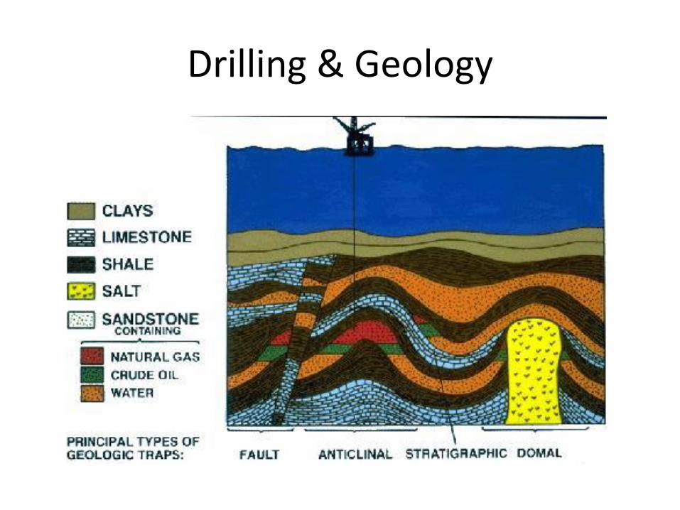
Drilling & Geology
65
Drilling & Geology Resource presentation for exercises related to Storvola & Festningen Kjell Kåre Fjelde – UiS
Transcript of Drilling & Geology
Drilling & Geology Resource presentation for exercises related to Storvola & Festningen
Kjell Kåre Fjelde – UiS
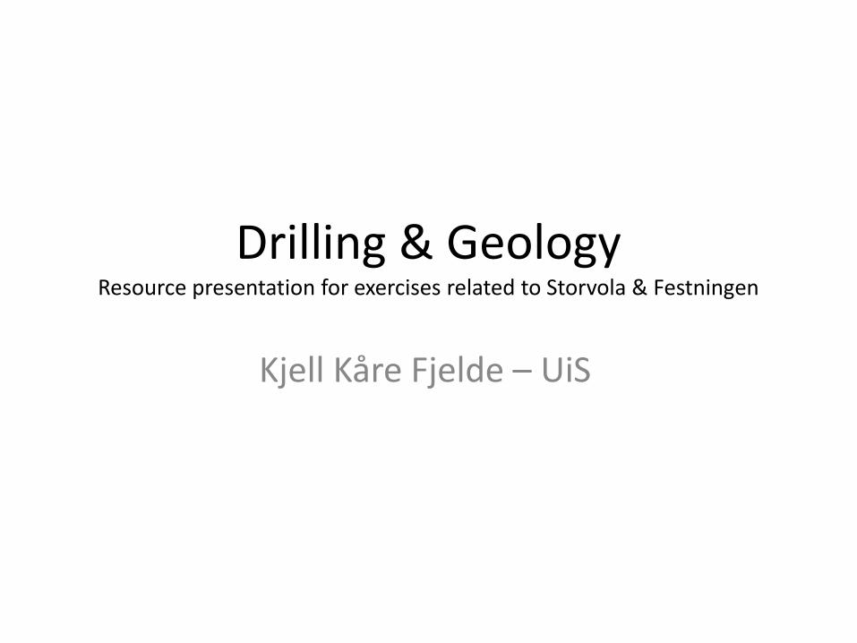
Festningen Exercise
• Solve an exercise that is focusing on elements to be considered when constructing a drilling program
• Can also be found on the resource CD
Festningen exercise
• Exercise handed out to each group in advance
• Work with it during the excursion and afterwards.
• Two groups will be selected to present and go through the assignment for discussion (powerpoint presentation)
Festningen Exercise
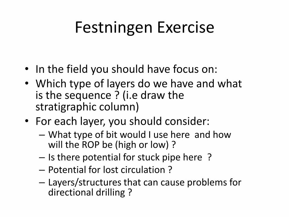
• In the field you should have focus on: • Which type of layers do we have and what
is the sequence ? (i.e draw the stratigraphic column)
• For each layer, you should consider: – What type of bit would I use here and how
will the ROP be (high or low) ? – Is there potential for stuck pipe here ? – Potential for lost circulation ? – Layers/structures that can cause problems for
directional drilling ?
Drilling & Geology
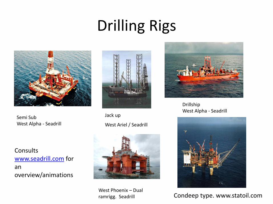
Drilling Rigs
Jack up
West Ariel / Seadrill
Semi Sub West Alpha - Seadrill
Drillship West Alpha - Seadrill
Condeep type. www.statoil.com West Phoenix – Dual ramrigg. Seadrill
Consults www.seadrill.com for an overview/animations
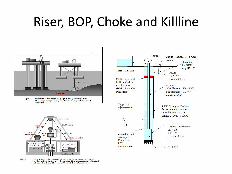
Riser, BOP, Choke and Killline
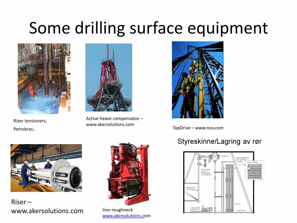
Some drilling surface equipment
Riser tensioners,
Petrobras.
Riser – www.akersolutions.com
Active heave compensator – www.akersolutions.com
Iron roughneck www.akersolutions.com
TopDrive – www.nov.com
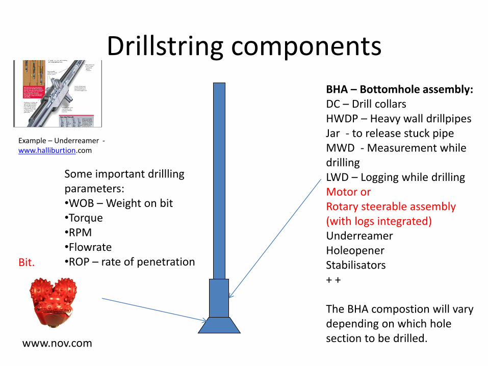
Drillstring components
BHA – Bottomhole assembly: DC – Drill collars HWDP – Heavy wall drillpipes Jar - to release stuck pipe MWD - Measurement while drilling LWD – Logging while drilling Motor or Rotary steerable assembly (with logs integrated) Underreamer Holeopener Stabilisators + + The BHA compostion will vary depending on which hole section to be drilled.
Bit.
www.nov.com
Example – Underreamer - www.halliburtion.com
Some important drillling parameters: •WOB – Weight on bit •Torque •RPM •Flowrate •ROP – rate of penetration
Drilling bits
Depending on the formation type, hardness and abbrasiveness – a proper bit has to be selected to optimise ROP etc. Consult the homepages of the different vendors to see which bit that is most approriate.
Some vendors
• National Oilwell (Reed Hycalog drillbits) – www.nov.com
• BakerHughes (Hughes Christensen) – www.bakerhughesdirect.com
• Smith – (www.smith.com)
• Varel – www.varelintl.com
• Halliburton – www.halliburton.com
ROP – rate of penetration
• ROP tells us how fast we drill. – (1 m/ hour – very slow, 60 m / hour – quite good)
• Low ROP - > Expensive operations.
• ROP will depend on formation hardness & bit choice
• Bit change (wear, failure etc) is time consuming & costs money
• Important to choose the right bit for the formation to ensure – As high ROP as possible
– Avoid wearing out the bits too early.
Formation hardness
• The choice of an approriate bit will depend on formation hardness & abrasiveness – Soft/Medium soft formation
• Shale, clay, limestone, sands.
– Medium hard/hard formation • Hard limestone, sandstone, dolomite
– Hard and abrasive formations • Granites, basalts, quartzite and chert
• Check www.adriatech.com for appropriate rock bits for the different formation types.
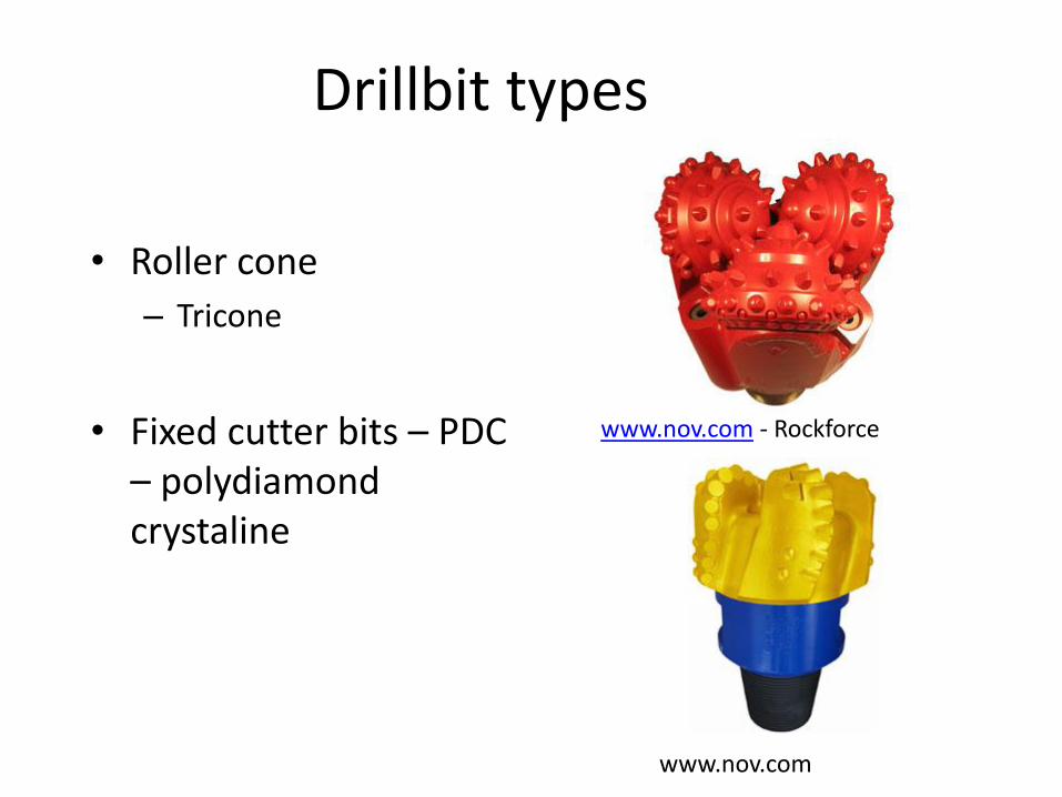
Drillbit types
• Roller cone
– Tricone
• Fixed cutter bits – PDC – polydiamond crystaline
www.nov.com - Rockforce
www.nov.com
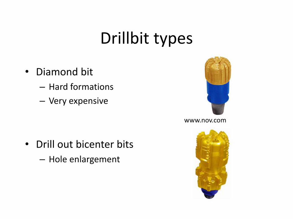
Drillbit types
• Diamond bit
– Hard formations
– Very expensive
• Drill out bicenter bits
– Hole enlargement
www.nov.com
Drillbit types
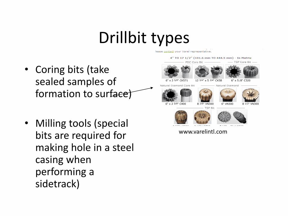
• Coring bits (take sealed samples of formation to surface)
• Milling tools (special bits are required for making hole in a steel casing when performing a sidetrack)
www.varelintl.com
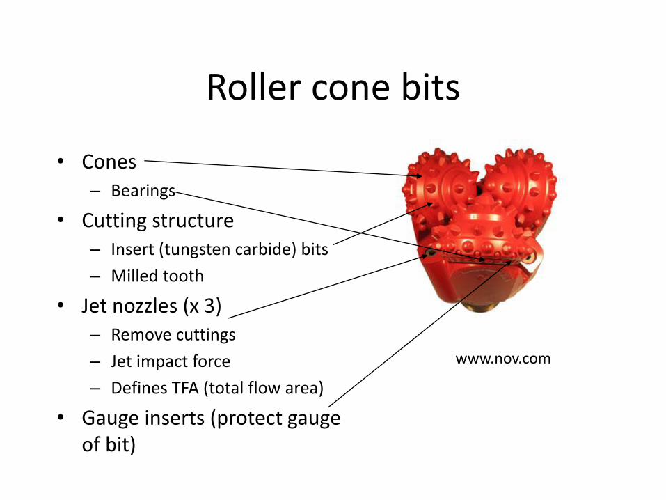
Roller cone bits
• Cones – Bearings
• Cutting structure – Insert (tungsten carbide) bits
– Milled tooth
• Jet nozzles (x 3) – Remove cuttings
– Jet impact force
– Defines TFA (total flow area)
• Gauge inserts (protect gauge of bit)
www.nov.com
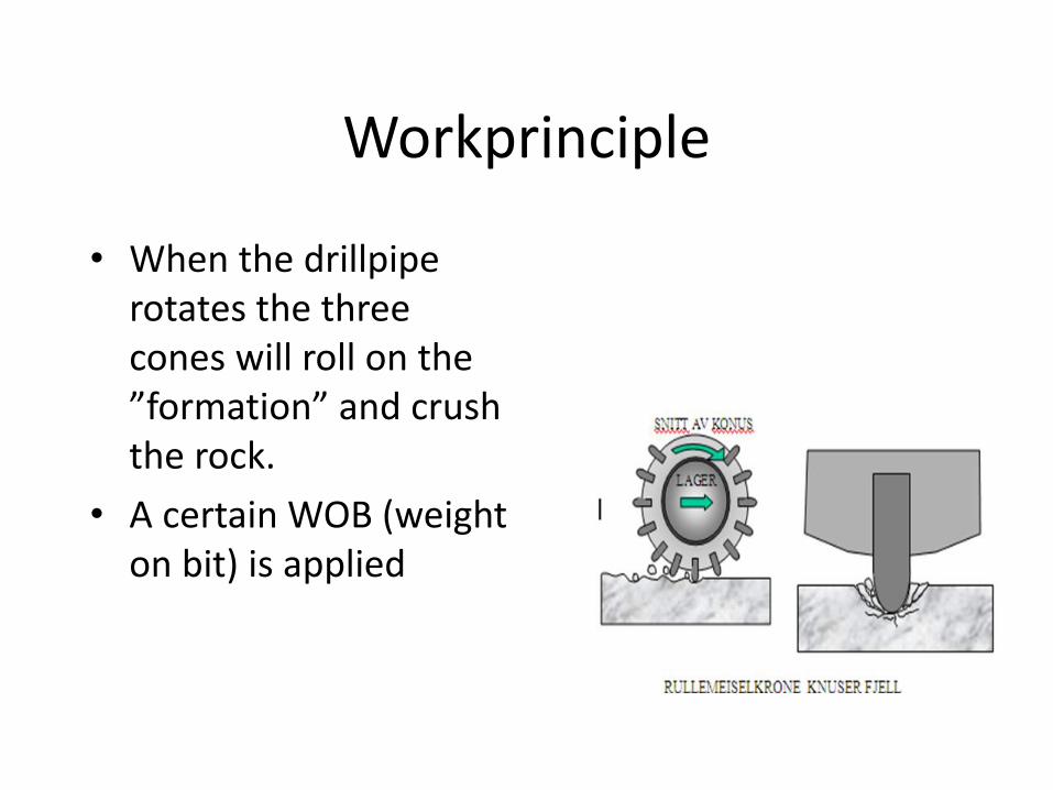
Workprinciple
• When the drillpipe rotates the three cones will roll on the ”formation” and crush the rock.
• A certain WOB (weight on bit) is applied
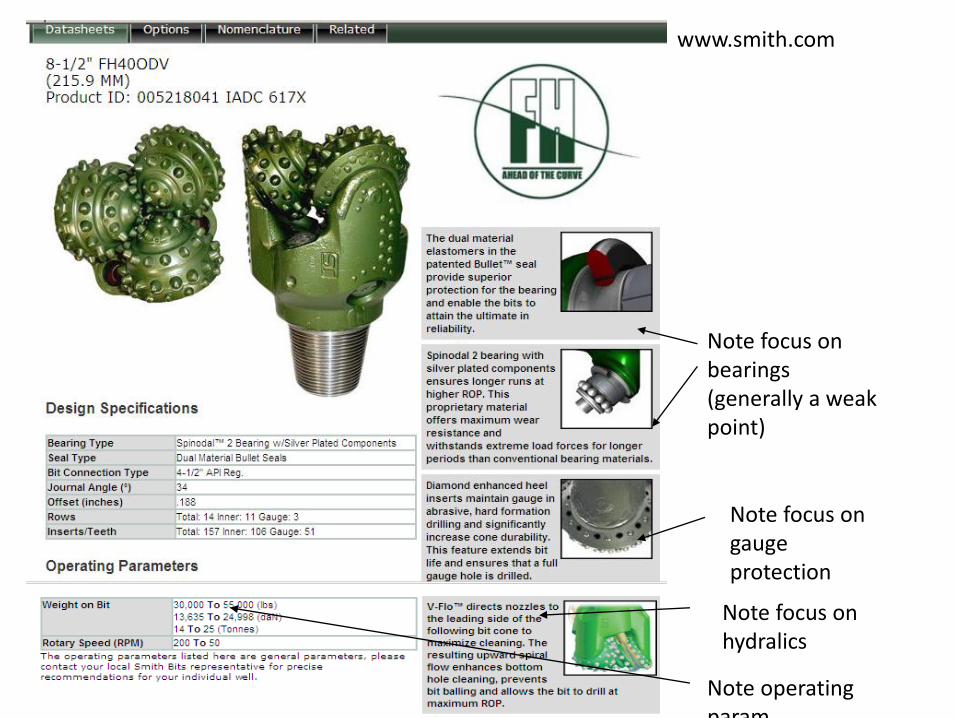
www.smith.com
Note operating param
Note focus on hydralics
Note focus on gauge protection
Note focus on bearings (generally a weak point)
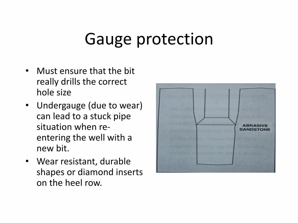
Gauge protection
• Must ensure that the bit really drills the correct hole size
• Undergauge (due to wear) can lead to a stuck pipe situation when re-entering the well with a new bit.
• Wear resistant, durable shapes or diamond inserts on the heel row.
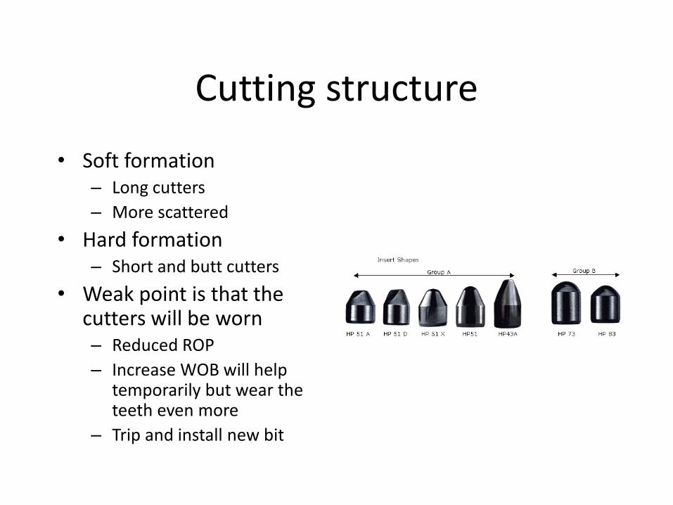
Cutting structure
• Soft formation – Long cutters
– More scattered
• Hard formation – Short and butt cutters
• Weak point is that the cutters will be worn – Reduced ROP
– Increase WOB will help temporarily but wear the teeth even more
– Trip and install new bit
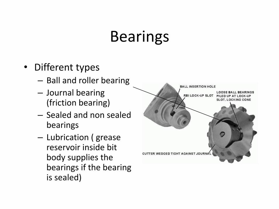
Bearings
• Different types – Ball and roller bearing
– Journal bearing (friction bearing)
– Sealed and non sealed bearings
– Lubrication ( grease reservoir inside bit body supplies the bearings if the bearing is sealed)
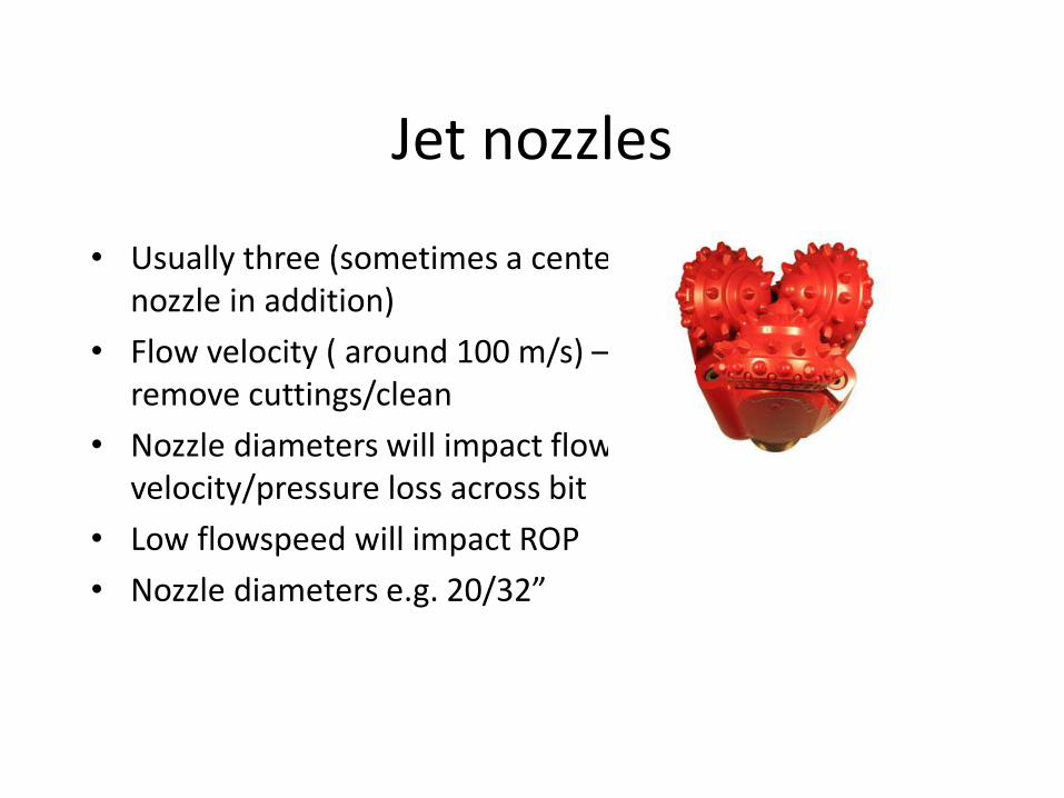
Jet nozzles
• Usually three (sometimes a center nozzle in addition)
• Flow velocity ( around 100 m/s) – remove cuttings/clean
• Nozzle diameters will impact flow velocity/pressure loss across bit
• Low flowspeed will impact ROP
• Nozzle diameters e.g. 20/32”
Roller cone application areas
• Steel tooth – Top hole, Soft formations
• Tungsten carbid inserts – Medium to very hard formations – Formations where PDC does not work – Drill out shoe (cement)
• Rate of penetration – Medium, Slow • Steerability – Good • More trips to change bit due to wear compared
to using PDC bits.
Some issues to be aware of
• Cones can be lost (fishing operations)
• The cutters will be worn down
• Bearings is a weak point
• Gauge wear
• Bit balling (bit packed with formation)
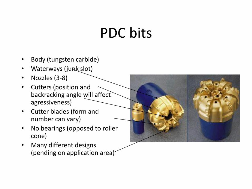
PDC bits
• Body (tungsten carbide)
• Waterways (junk slot)
• Nozzles (3-8)
• Cutters (position and backracking angle will affect agressiveness)
• Cutter blades (form and number can vary)
• No bearings (opposed to roller cone)
• Many different designs (pending on application area)
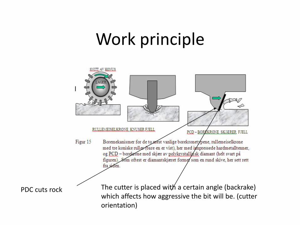
Work principle
PDC cuts rock The cutter is placed with a certain angle (backrake) which affects how aggressive the bit will be. (cutter orientation)
PDC Cutters
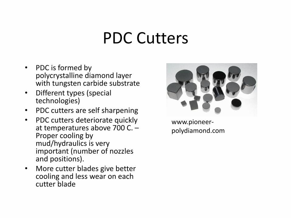
• PDC is formed by polycrystalline diamond layer with tungsten carbide substrate
• Different types (special technologies)
• PDC cutters are self sharpening • PDC cutters deteriorate quickly
at temperatures above 700 C. – Proper cooling by mud/hydraulics is very important (number of nozzles and positions).
• More cutter blades give better cooling and less wear on each cutter blade
www.pioneer-polydiamond.com
Application areas
• Soft to medium hard formations (not applicable in very hard & abrasive formations)
• Shales are easier to drill (ROP) than limestone/sandstone and PDC bits usually drills twice as fast in shale compared to roller cone
• Lower sections (12 ¼” hole ->) • Steerable and rotary applications (motor & RSS) • High ROP (opposed to roller cones) • More expensive • More robust (fewer trips compared to roller cone) • Steerability depends on design
– Aggressives of cutters – Backrake of cutters – Blade count – etc
Bit stability – important in design
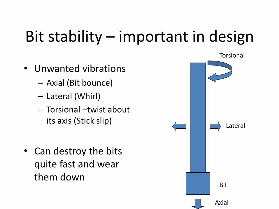
• Unwanted vibrations
– Axial (Bit bounce)
– Lateral (Whirl)
– Torsional –twist about its axis (Stick slip)
• Can destroy the bits quite fast and wear them down
Torsional
Lateral
Axial
Bit
Vibration roller cone
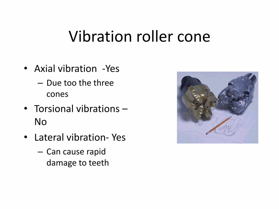
• Axial vibration -Yes
– Due too the three cones
• Torsional vibrations – No
• Lateral vibration- Yes
– Can cause rapid damage to teeth
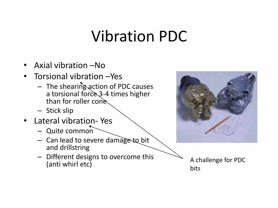
Vibration PDC
• Axial vibration –No • Torsional vibration –Yes
– The shearing action of PDC causes a torsional force 3-4 times higher than for roller cone
– Stick slip
• Lateral vibration- Yes – Quite common – Can lead to severe damage to bit
and drillstring – Different designs to overcome this
(anti whirl etc)
A challenge for PDC bits
Vibration - PDC
• To reduce vibrations and increase the stability of the bit is a very important part of the bit design process.
• When using PDC bit in a very hard formation (e.g. hard abrasive sandstone), the bit can easily be destroyed by vibrations (SPE 79797).
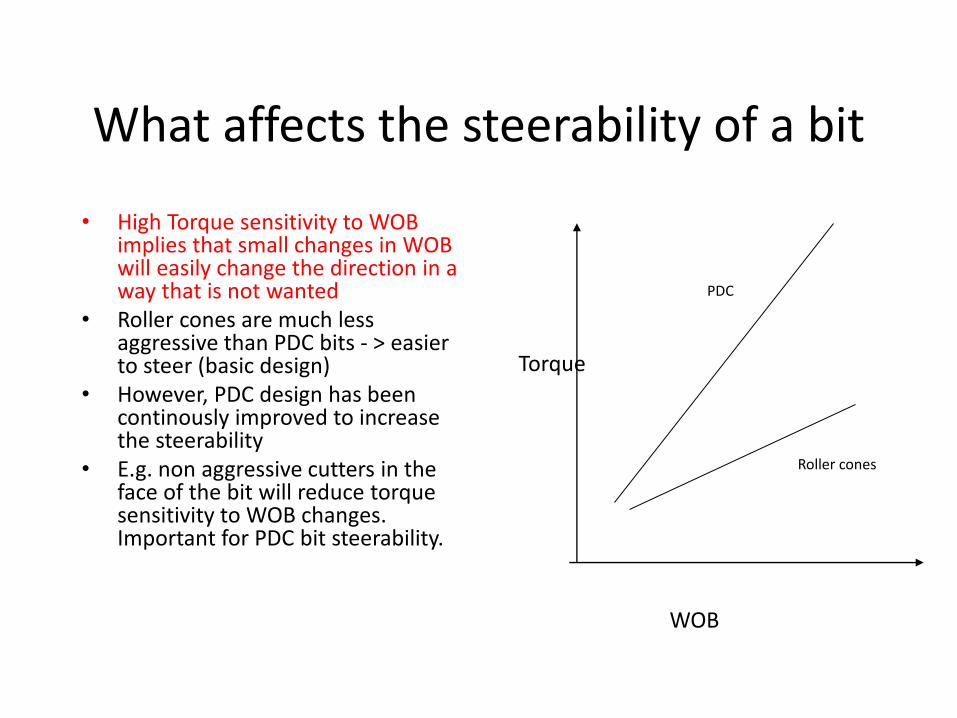
What affects the steerability of a bit
• High Torque sensitivity to WOB implies that small changes in WOB will easily change the direction in a way that is not wanted
• Roller cones are much less aggressive than PDC bits - > easier to steer (basic design)
• However, PDC design has been continously improved to increase the steerability
• E.g. non aggressive cutters in the face of the bit will reduce torque sensitivity to WOB changes. Important for PDC bit steerability.
WOB
Torque
Roller cones
PDC
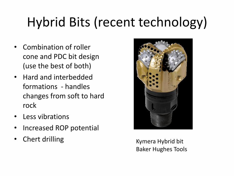
Hybrid Bits (recent technology)
• Combination of roller cone and PDC bit design (use the best of both)
• Hard and interbedded formations - handles changes from soft to hard rock
• Less vibrations
• Increased ROP potential
• Chert drilling
Kymera Hybrid bit Baker Hughes Tools
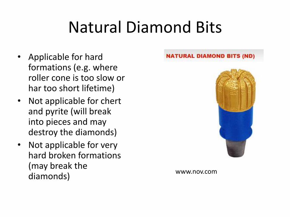
Natural Diamond Bits
• Applicable for hard formations (e.g. where roller cone is too slow or har too short lifetime)
• Not applicable for chert and pyrite (will break into pieces and may destroy the diamonds)
• Not applicable for very hard broken formations (may break the diamonds)
www.nov.com
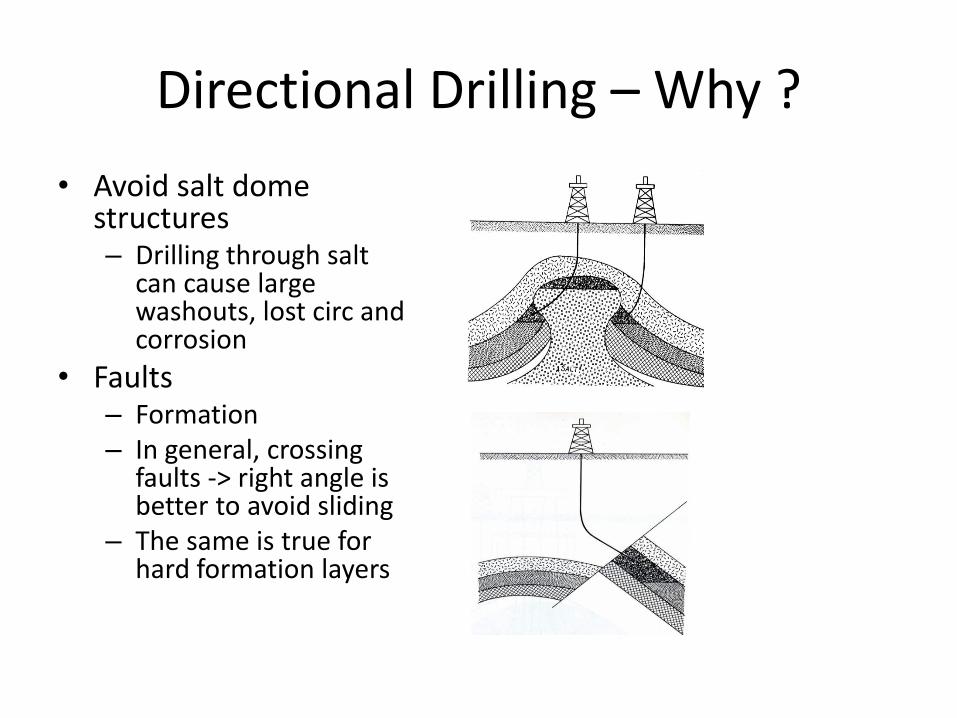
Directional Drilling – Why ?
• Avoid salt dome structures – Drilling through salt
can cause large washouts, lost circ and corrosion
• Faults – Formation – In general, crossing
faults -> right angle is better to avoid sliding
– The same is true for hard formation layers
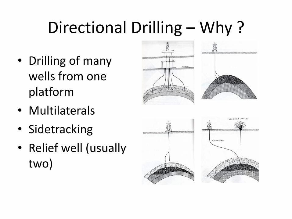
Directional Drilling – Why ?
• Drilling of many wells from one platform
• Multilaterals
• Sidetracking
• Relief well (usually two)
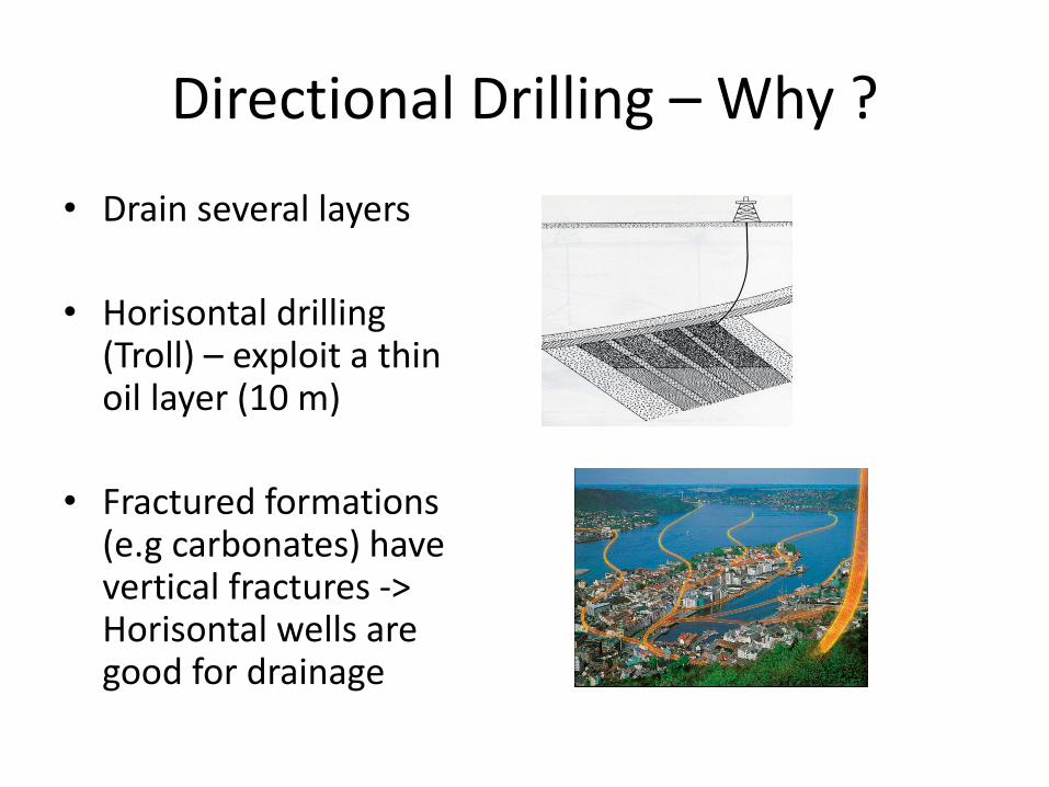
Directional Drilling – Why ?
• Drain several layers
• Horisontal drilling (Troll) – exploit a thin oil layer (10 m)
• Fractured formations (e.g carbonates) have vertical fractures -> Horisontal wells are good for drainage
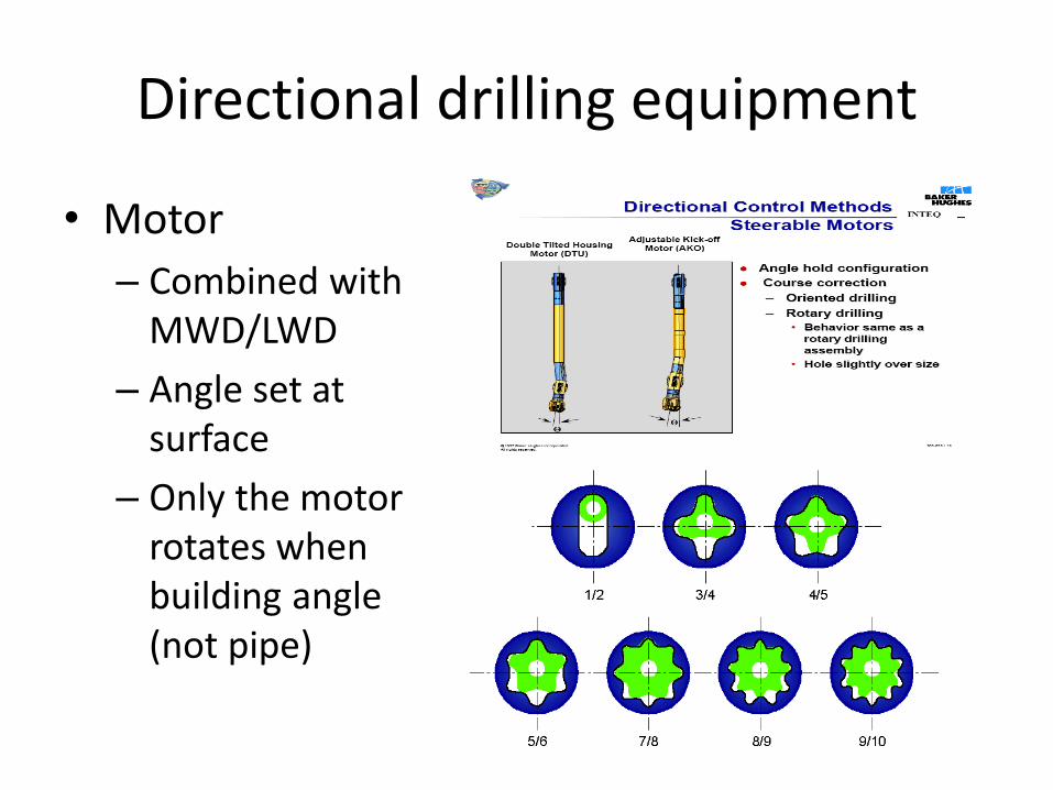
Directional drilling equipment
• Motor
– Combined with MWD/LWD
– Angle set at surface
– Only the motor rotates when building angle (not pipe)
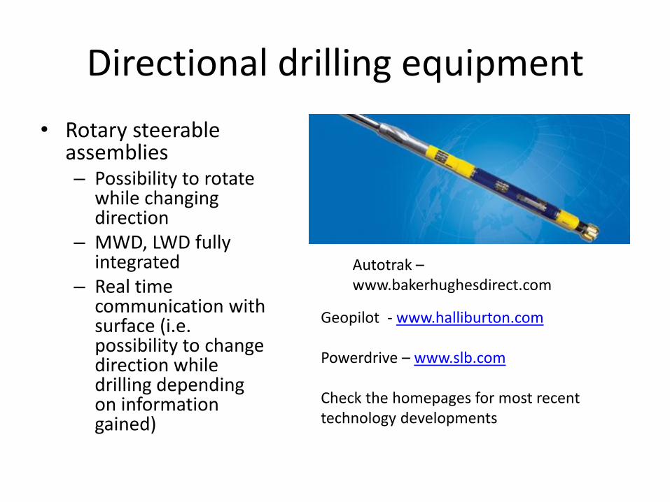
Directional drilling equipment
• Rotary steerable assemblies – Possibility to rotate
while changing direction
– MWD, LWD fully integrated
– Real time communication with surface (i.e. possibility to change direction while drilling depending on information gained)
Autotrak – www.bakerhughesdirect.com
Geopilot - www.halliburton.com Powerdrive – www.slb.com Check the homepages for most recent technology developments
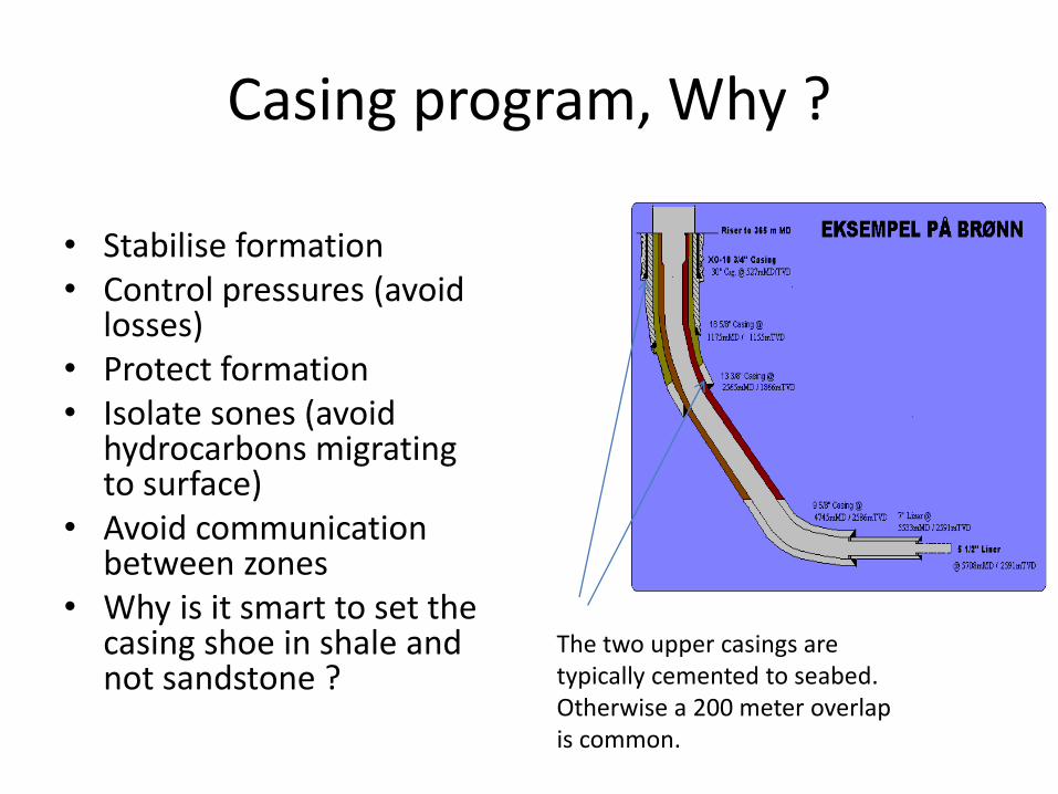
Casing program, Why ?
• Stabilise formation • Control pressures (avoid
losses) • Protect formation • Isolate sones (avoid
hydrocarbons migrating to surface)
• Avoid communication between zones
• Why is it smart to set the casing shoe in shale and not sandstone ?
The two upper casings are typically cemented to seabed. Otherwise a 200 meter overlap is common.
Casing program, why ?
• Install equipment/completion
• Reduce well friction
• Isolate sones – Avoid contamination
– Avoid unwanted production • Coning
• Shut off gas/water bearing formation
– Possibility to control production from different layers.
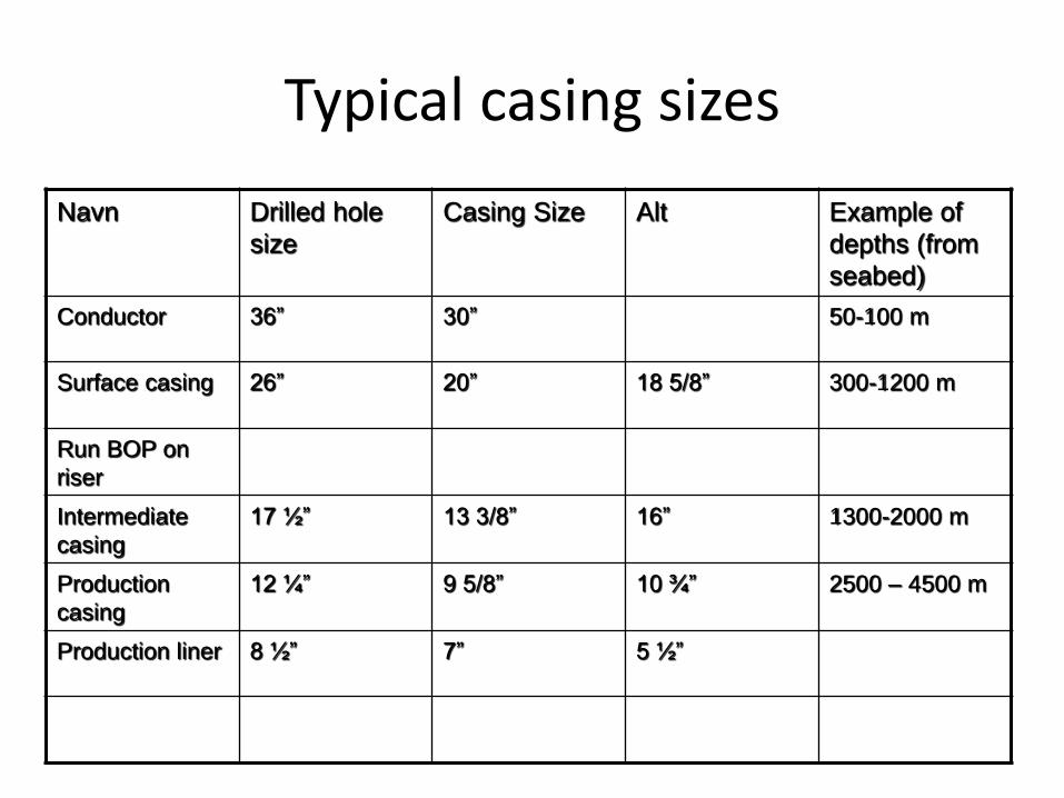
Typical casing sizes
Navn Drilled hole
size
Casing Size Alt Example of
depths (from
seabed)
Conductor 36” 30” 50-100 m
Surface casing 26” 20” 18 5/8” 300-1200 m
Run BOP on
riser
Intermediate
casing
17 ½” 13 3/8” 16” 1300-2000 m
Production
casing
12 ¼” 9 5/8” 10 ¾” 2500 – 4500 m
Production liner 8 ½” 7” 5 ½”
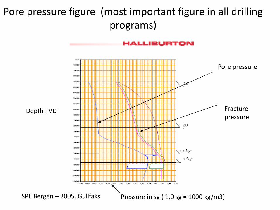
Pore pressure figure (most important figure in all drilling programs)
SPE Bergen – 2005, Gullfaks Pressure in sg ( 1,0 sg = 1000 kg/m3)
Depth TVD
Pore pressure
Fracture pressure
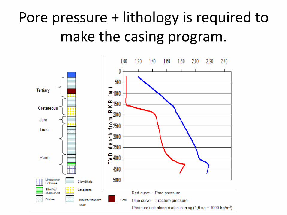
Pore pressure + lithology is required to make the casing program.
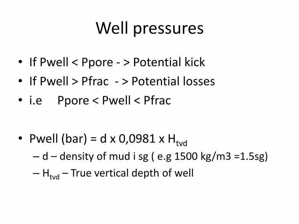
Well pressures
• If Pwell < Ppore - > Potential kick
• If Pwell > Pfrac - > Potential losses
• i.e Ppore < Pwell < Pfrac
• Pwell (bar) = d x 0,0981 x Htvd
– d – density of mud i sg ( e.g 1500 kg/m3 =1.5sg)
– Htvd – True vertical depth of well
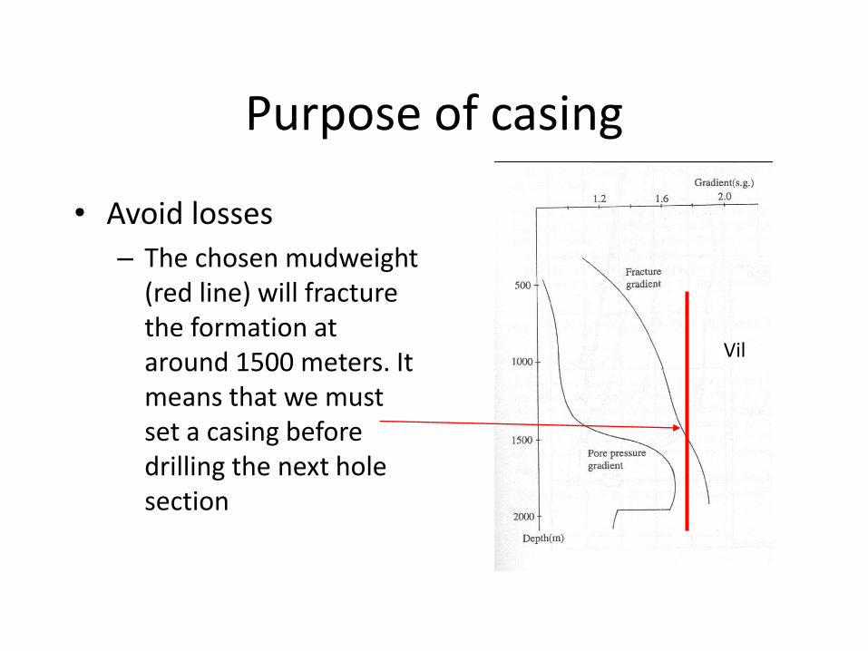
Purpose of casing
• Avoid losses
– The chosen mudweight (red line) will fracture the formation at around 1500 meters. It means that we must set a casing before drilling the next hole section
Vil
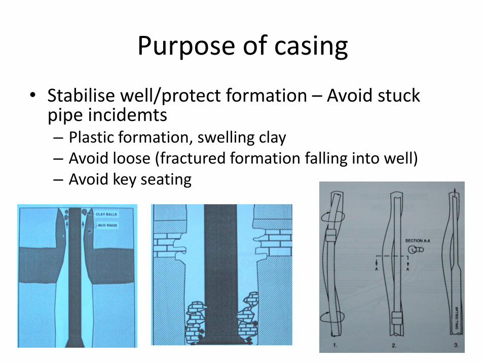
Purpose of casing
• Stabilise well/protect formation – Avoid stuck pipe incidemts – Plastic formation, swelling clay – Avoid loose (fractured formation falling into well) – Avoid key seating
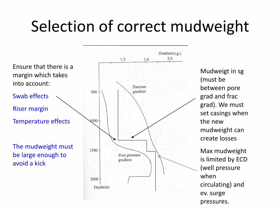
Selection of correct mudweight
Mudweigt in sg (must be between pore grad and frac grad). We must set casings when the new mudweight can create losses
Max mudweight is limited by ECD (well pressure when circulating) and ev. surge pressures.
Ensure that there is a margin which takes into account:
Swab effects
Riser margin
Temperature effects
The mudweight must be large enough to avoid a kick
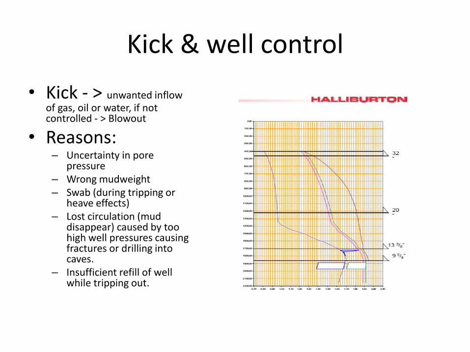
Kick & well control
• Kick - > unwanted inflow of gas, oil or water, if not controlled - > Blowout
• Reasons: – Uncertainty in pore
pressure – Wrong mudweight – Swab (during tripping or
heave effects) – Lost circulation (mud
disappear) caused by too high well pressures causing fractures or drilling into caves.
– Insufficient refill of well while tripping out.
Well kill
• After the kick has been detected. – Close BOP – Monitor shut in pressures – Open choke and circulate the kick out through
chokeline to separator/flare • Drillers method (kill mud after the kick has been circ out) • Wait and weight (circulate kill mud immediately)
– Bullheading • Last option method – reverse kill by pumping/forcing kick
back into formation • Reasons (H2S, unacceptable large kick volumes that can
break down the formations on its way up)
BOP - Barrier
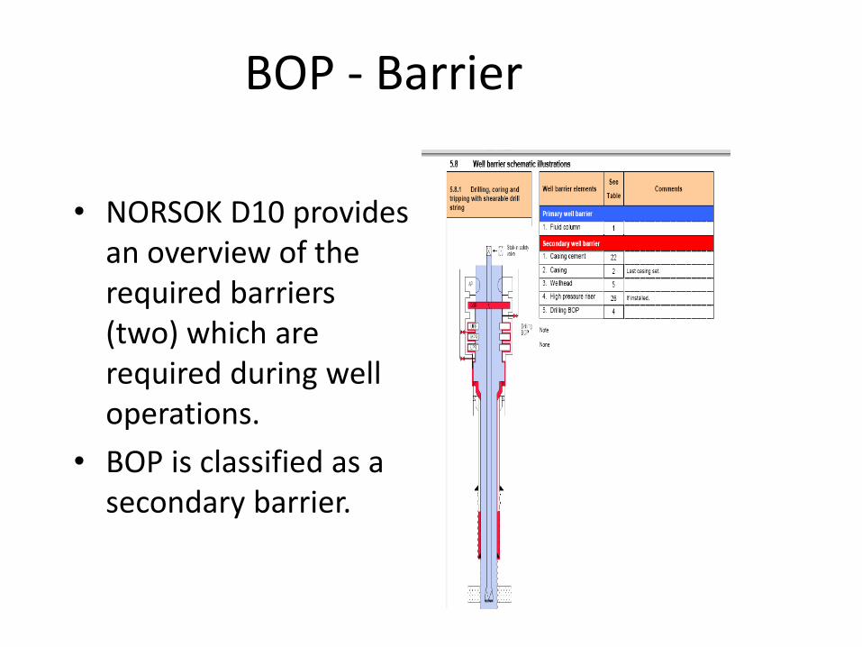
• NORSOK D10 provides an overview of the required barriers (two) which are required during well operations.
• BOP is classified as a secondary barrier.
Chokeline, Killine, Choke
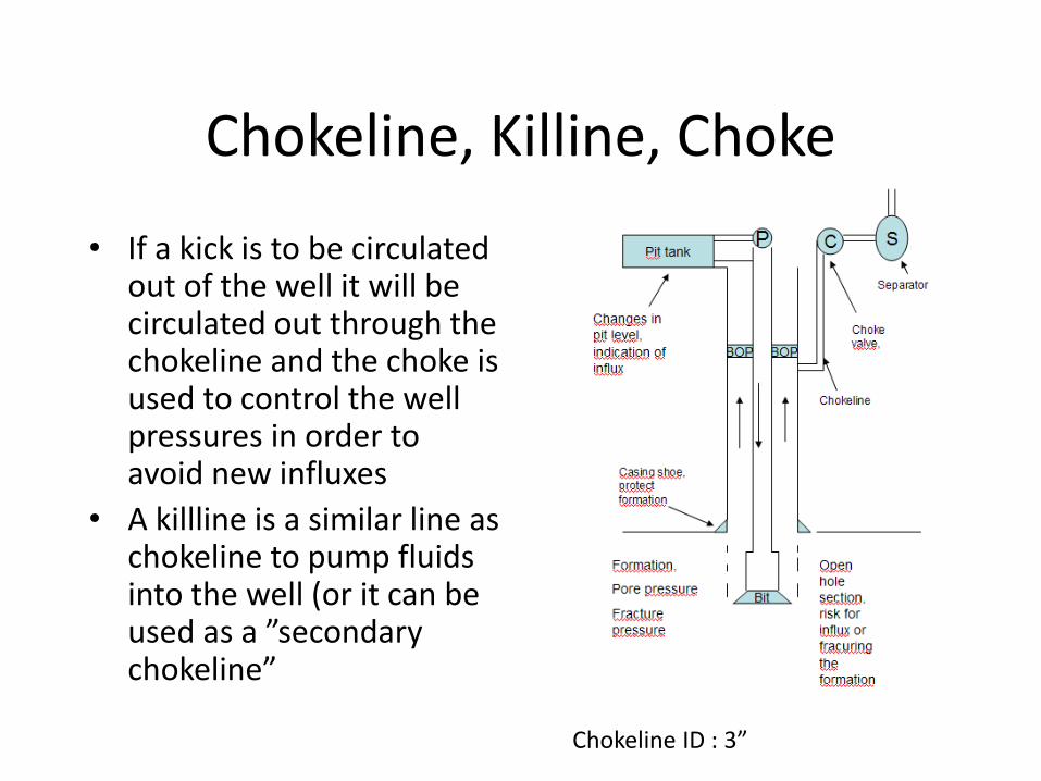
• If a kick is to be circulated out of the well it will be circulated out through the chokeline and the choke is used to control the well pressures in order to avoid new influxes
• A killline is a similar line as chokeline to pump fluids into the well (or it can be used as a ”secondary chokeline”
Chokeline ID : 3”
Separator
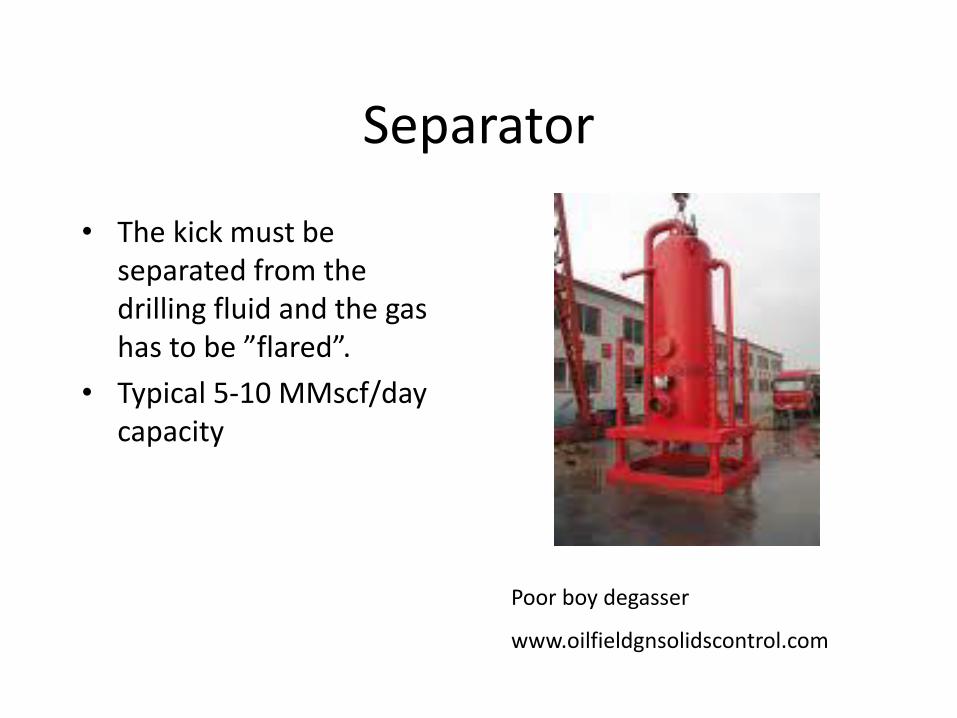
• The kick must be separated from the drilling fluid and the gas has to be ”flared”.
• Typical 5-10 MMscf/day capacity
Poor boy degasser
www.oilfieldgnsolidscontrol.com
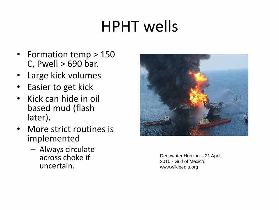
HPHT wells
• Formation temp > 150 C, Pwell > 690 bar.
• Large kick volumes • Easier to get kick • Kick can hide in oil
based mud (flash later).
• More strict routines is implemented – Always circulate
across choke if uncertain.
Deepwater Horizon – 21 April
2010.- Gulf of Mexico,
www.wikipedia.org
Choice of type of mud
• OBM (oil based mud) – Advantage:
• Often more compatible with the reservoir • Less risk for fracturing the well at the last casing shoe in case
of a kick (HPHT) • Reduce problem with swelling clay, thinner mud filter cake ->
reduced risk for getting stuck.
– Disadvantage • HSE, environment, more expensive • Can be difficult to detects kicks in HPHT wells (the gas influx
will hide in the mud) -> Special HPHT procedures are introduced in drilling to reduce the problem.
Choice of type of mud
• WBM (water based mud) – Often used in the upper sections
– Advantage: • Cheaper, less HSE issues, more environmental friendly
• Easier to detect kicks in HPHT wells (High pressure, high temperature wells)
– Disadvantage: • Swelling Clay/Shale
• Less lubrication
• Thicker mudcake /easier to get differential stuck
Geology related drilling problems
• Stuck pipe is one of the more severe events that can occur during drilling and can lead to large costs – Fishing operation
– In worst case, a sidetrack is the final solution.
• Three main causes – Mechanical related
– Formation related
– Differential sticking (pressure related)
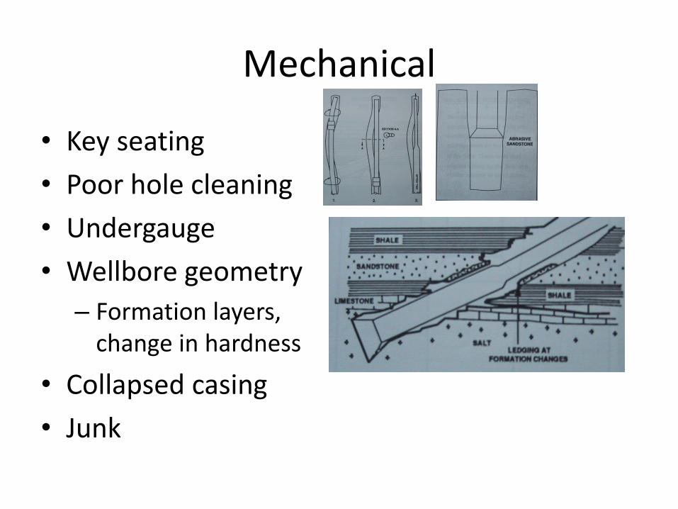
Mechanical
• Key seating
• Poor hole cleaning
• Undergauge
• Wellbore geometry
– Formation layers, change in hardness
• Collapsed casing
• Junk
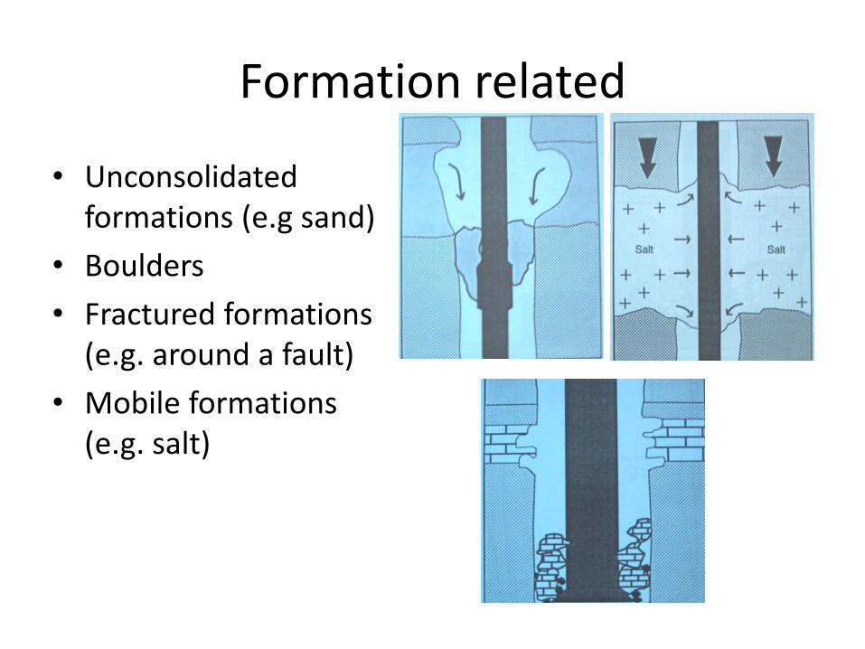
Formation related
• Unconsolidated formations (e.g sand)
• Boulders
• Fractured formations (e.g. around a fault)
• Mobile formations (e.g. salt)
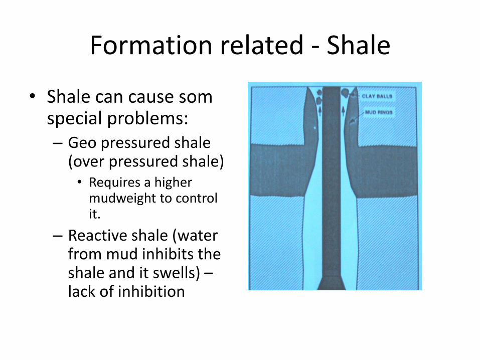
Formation related - Shale
• Shale can cause som special problems: – Geo pressured shale
(over pressured shale) • Requires a higher
mudweight to control it.
– Reactive shale (water from mud inhibits the shale and it swells) – lack of inhibition
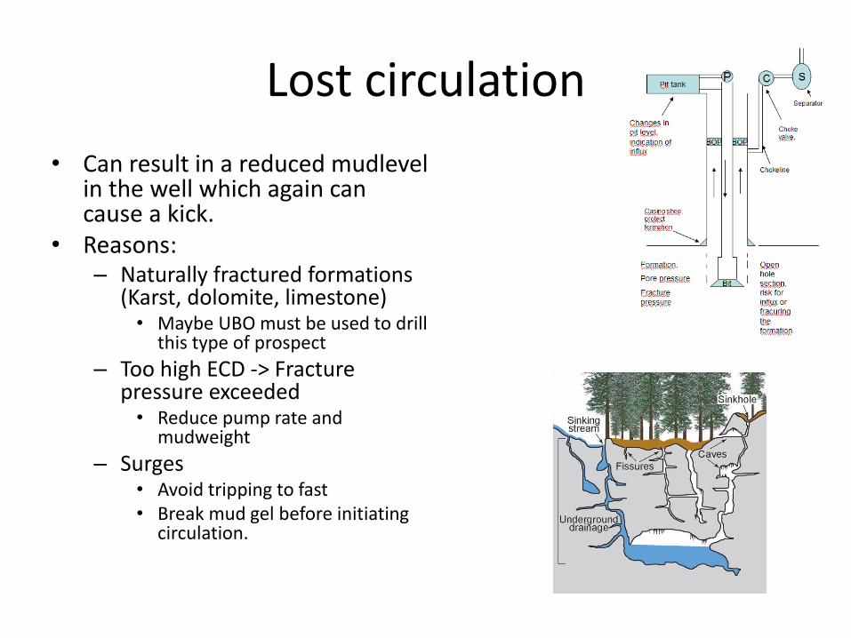
Lost circulation
• Can result in a reduced mudlevel in the well which again can cause a kick.
• Reasons: – Naturally fractured formations
(Karst, dolomite, limestone) • Maybe UBO must be used to drill
this type of prospect
– Too high ECD -> Fracture pressure exceeded
• Reduce pump rate and mudweight
– Surges • Avoid tripping to fast • Break mud gel before initiating
circulation.
Lost circulation
• LCM – Lost circulation material pills are pumped (marbles etc ) to try to plug the fractures.
• Note that a lost circulation incident can have some very negative consequences – Increase Kick probability
– Reduced cuttings transport -> possible stuck pipe
– Reduced fracture pressure next time
– Possible collapse of well
Lost circulation
• Important to identify potential loss circulation sones in advance. – Seismic, geology
• Isolate potential low pressure sones with casings
• Control ECD, cuttings transport
• Avoid pressure surges
• Have equipment ready for injecting LCM into well.