DressView Dressing system - BMR GmbH€¦ · -Menu with the MENU-Key and the menu point DressView...
32
…when it comes to quality! BMR GmbH 1
Transcript of DressView Dressing system - BMR GmbH€¦ · -Menu with the MENU-Key and the menu point DressView...

…when it comes to quality! BMR GmbH 1

2 DressView Dressing system
…when it comes to quality! BMR GmbH 1
Issue June 2017
1 Introduction - Overview 3
2 Key Functions 5
3 Menu Structure 6
3.1 Main Menu 7
3.2 Terminal-Menu 8
3.2.1 Adjusting the rotational speed of the spindle 8
3.3 Characteristic-Menu 9
3.3.1 Selection of a characteristic 9
3.4 Dressing-Menu 10
3.4.1 DressView-Configuration menu 10
3.4.1.1 Adjusting the rotational speed 10
3.4.1.2 Display mode / changing the function 11
3.4.1.3 Alternating 11
3.4.1.4 Invert colors 12
3.4.1.5 Negative values 12
3.4.1.6 Shadow or Ghost images 12
3.4.1.7 Time base 12
3.4.1.8 Automatic scaling the time base 12
3.4.1.9 Scaling 13
3.4.1.10 Zoom 10% 13
3.4.1.11 Crash level 13
3.4.1.12 enabled 14
3.4.1.13 Save changes 14
3.4.1.14 Graph-Button 14
3.4.2 Dressing 15
3.4.2.1 Basics 16
3.4.2.2 Additional display functions 16
3.4.2.3 Behaviour of the inputs and outputs 17
3.5 Debug-Menu 18
3.5.1 Digital inputs and outputs (not yet implemented) 18
3.5.2 Analogue inputs and outputs (not yet implemented) 18
2 DressView Dressing system
3.5.3 Status- and error messages 19
3.6 Setup menu 20
3.6.1 System language 20
3.6.2 Settings for the Terminal menu 20
3.6.2.1 Display of Vario-load 20
3.6.2.2 Value of Vario-load 20
3.6.3 General settings 21
3.6.3.1 Boot window 21
3.6.3.2 Direction of rotation 21
3.6.3.3 Update 21
4 Use of the system in the drilling / milling 22
5 DressView ®-specific inputs and outputs 23
6 USB-Interface 24
7 Connection 24
7.1 Connecting the SSE-System 24
8 Delivery contents 25
9 Dimensions and Mounting 26

…when it comes to quality! BMR GmbH 3
1 Introduction - Overview In the abrasive industry grinding tools are worn or dull after a certain process time
and cannot thus guarantee the precision in machining. In this case, they must be
brought in form or sharpened again, which is called "dressing".
This dressing is generally a very important feature because it is controlling directly the
quality of the product but on the other hand a lot of process time is lost. The goal is
to produce always the most accurate surface precision and simultaneously remove as
little material as possible.
When dressing, there are two basic methods, first the use of stationary dressing tools
and second the use of rotating tools.
For highest accuracy mostly the latter method is used, and is supported for
reconsideration increasing the precision usually also through the use of sensor
systems subject. In this case, sensors are installed in the spindle, that are connected
to an additional electronic evaluation system.
The DressView® system is a completely new and innovative system and takes a
different approach. It works without sensors and yet allows process precisions of
0.5 - 1 microns, and is thus in a similar capacity range as sensor-prone systems.
The DressView® system of BMR works together with frequency converters of BMR
and dressing spindles in a mounting range from 33mm to 72mm and is available in
two different versions and performance classes. For capacities up to 3 kW it is
available as DressView-0303 and for lower power ratings up to 400VA as DressView-
0200.
Moreover, both versions are also available in two versions either as a desktop unit or
as cabinet solution.
The integrated solution in a desktop version includes the drive and the DressView
system along with the LCD so it is immediately ready for connection.
The separate version as DressView-SSE is particularly suitable for use in control
cabinets. Here the BMR drive and the DressView dock for DressView® is then
installed. All signals from and to the PLC are wired here and DressView display can be
mounted directly on the machine. Only a slim cable as "umbilical cord" is then
connected with the docking station and the drive.
A characteristic control signal is derived, and graphically presented on a LCD display
from the operation of the spindle. For signal output to the PLC in each case a limit
value for signal detection and, in addition, a higher one can be set to a potential crash
detection.
The DressView® system is easily operated and adjusted via laterally arranged
membrane keys. Various settings can be made for the dressing process, such as the
afterglow of last measurement processes as silhouettes and the time base or the

4 DressView Dressing system
scaling of the display
For communication with the PLC 3 digital inputs, 3 digital outputs and one analog
output are available. Using
indicated. The analog output
dressing.
With this system BMR has succeeded in creating a bridge between the existing
concepts and to combine the best of both worlds. It is a system with a very high
resolution with modest cost and low follow
be used, because - the spindle is the sensor.
Dressing system
For communication with the PLC 3 digital inputs, 3 digital outputs and one analog
Using them the system can be started and the current status
. The analog output is derived directly from the measurement signal of the
succeeded in creating a bridge between the existing
concepts and to combine the best of both worlds. It is a system with a very high
resolution with modest cost and low follow-up costs because standard
the spindle is the sensor.
For communication with the PLC 3 digital inputs, 3 digital outputs and one analog
the system can be started and the current status is
irectly from the measurement signal of the
succeeded in creating a bridge between the existing
concepts and to combine the best of both worlds. It is a system with a very high
p costs because standard spindles can

2 Key Functions
Display Control
1
2
3
4
5
Number Key Function
1 MENU jump one level ahead , back, Open menu
2 ↑ Increase value or shifts up (graph menu)
3 SELECT Jump to the next selectable item
4 ↓ Reduce value or shifts down (graph menu)
5 ENTER confirms a selection
6 START Spindle Start
7 + To increase speed of spindle
8 ↔ Selects digit, where speed value is to be changed
(100, 1.000 or 10.000 digit)
9 - To reduce speed of spindle
10 STOP Spindle Stop
In case it is not selected the T
jump back to the Terminal Menu with the keys of "Spindle Control" in order to start,
stop the spindle or change it's rotational speed
…when it comes to quality!
Function
jump one level ahead , back, Open menu
Increase value or shifts up (graph menu)
Jump to the next selectable item
Reduce value or shifts down (graph menu)
confirms a selection
Spindle Start
To increase speed of spindle
Selects digit, where speed value is to be changed
(100, 1.000 or 10.000 digit)
To reduce speed of spindle
Spindle Stop
In case it is not selected the Terminal- or Dressing Menu, there is the possibility to
jump back to the Terminal Menu with the keys of "Spindle Control" in order to start,
stop the spindle or change it's rotational speed
…when it comes to quality! BMR GmbH 5
Spindle Control
6
7
8
9
10
Selects digit, where speed value is to be changed
Dressing Menu, there is the possibility to
jump back to the Terminal Menu with the keys of "Spindle Control" in order to start,

6 DressView Dressing system
3 Menu Structure
Main Menu
Terminal-
Menu
Spindle
Characteristics
Dressing-
Menu
Debug-
Menu
Setup-
Menu
Dressing system

3.1 Main Menu
In the Main Menu all functions of the
Moreover it shows the date
connected and it's number of firmware version.
This menu can be accessed by actuating the
…when it comes to quality!
In the Main Menu all functions of the DressView®-system can be accessed
oreover it shows the date and number of version, the type of converter being
connected and it's number of firmware version.
menu can be accessed by actuating the MENU-key one or several times.
…when it comes to quality! BMR GmbH 7
can be accessed.
of version, the type of converter being
key one or several times.

8 DressView Dressing system
3.2 Terminal-Menu
The Terminal-Menu is the window where all basic functions of
controlled. With the Keys "
to start and stop the spindle and to set up it's rotational speed. Furthermore the
current status messages of the converter are displayed, such as selected
characteristic, direction of rotation and load status.
displayed in the status area, whose background then turn red.
3.2.1 Adjusting the rotational speed of
Adjusting the rotational speed is carried out with the "+" and "
located to the right of the display. The speed will not change with
safety reasons, but enables the function.
After that, the background colour of this field changes into white. Additionally the
range of speed being possible with this spindle is displayed in the
With pressing on "+" or "-"
adjusted. The selection of the according digit in the range of 100, 1.000 or 10.000
value can be carried out with the Double arrow
Enter confirms this setting and applies the rotational speed
Dressing system
Menu is the window where all basic functions of the converter can be
controlled. With the Keys "START", "STOP", "+", "-" and "double arrow
to start and stop the spindle and to set up it's rotational speed. Furthermore the
current status messages of the converter are displayed, such as selected
characteristic, direction of rotation and load status. If an error appears it will
e status area, whose background then turn red.
Adjusting the rotational speed of the spindle
Adjusting the rotational speed is carried out with the "+" and "-" spindle control keys
located to the right of the display. The speed will not change with
safety reasons, but enables the function.
After that, the background colour of this field changes into white. Additionally the
range of speed being possible with this spindle is displayed in the
" the digit being indicated with a blue underscore can be
adjusted. The selection of the according digit in the range of 100, 1.000 or 10.000
value can be carried out with the Double arrow-key.
confirms this setting and applies the rotational speed
the converter can be
double arrow" it is possible,
to start and stop the spindle and to set up it's rotational speed. Furthermore the
current status messages of the converter are displayed, such as selected
If an error appears it will
" spindle control keys
located to the right of the display. The speed will not change with the first hit, for
After that, the background colour of this field changes into white. Additionally the
range of speed being possible with this spindle is displayed in the Status-field
the digit being indicated with a blue underscore can be
adjusted. The selection of the according digit in the range of 100, 1.000 or 10.000

3.3 Characteristic-Menu
To change the current selected spindle characteristic or list all available
characteristics, it has to be moved to the Main
it has to be navigated with the
Selection" and confirmed with
After that, a list of all characteristics being stored in the converter will be uploaded
and displayed. The current selected characteristic is marked with a
3.3.1 Selection of a characteristic
To select a certain characteristic
menu it has to be moved to the respective characterist
finally this selection has to be confirmed with
Depending on the type of converter, i
which takes around 3s. Within this time no further setup is possible
…when it comes to quality!
Menu
To change the current selected spindle characteristic or list all available
characteristics, it has to be moved to the Main-Menu by pressing
it has to be navigated with the SELECT or Arrow Keys to the point "
" and confirmed with ENTER.
After that, a list of all characteristics being stored in the converter will be uploaded
and displayed. The current selected characteristic is marked with a
of a characteristic
haracteristic to be used in the inverter, in the characteristics
to the respective characteristic with the
finally this selection has to be confirmed with ENTER.
Depending on the type of converter, it will be carried out a reset on the converter,
which takes around 3s. Within this time no further setup is possible
…when it comes to quality! BMR GmbH 9
To change the current selected spindle characteristic or list all available
Menu by pressing MENU. Being there,
to the point "Characteristic
After that, a list of all characteristics being stored in the converter will be uploaded
and displayed. The current selected characteristic is marked with a green marker.
in the characteristics
c with the Arrow Keys and
t will be carried out a reset on the converter,
which takes around 3s. Within this time no further setup is possible

10 DressView Dressing system
3.4 Dressing-Menu
In case it is intended to carry out a
the current window to the Main
Dressing to be selected. From there it is entered the
menu.
3.4.1 DressView-Configuration
In the DressView®-Configuration
be set up being required in advance for dressing operation.
All settings will be saved and after reentering automatically reloaded.
3.4.1.1 Adjusting the rotational speed
With pressing on "+" or "-" the digit being indicated with a blue underscore can be
adjusted. The selection of the according digit in the range of 100, 1.000 or 10.000
value can be carried out with the Double arrow
START, Save-Button or leaving the window
rotational speed
In case that the current setting is equal to
the speed field will be placed a
switched to LOW. Precondition for entering the Ready state again, is carrying out a
calibration while the spindle is running wit
Dressing system
it is intended to carry out a dressing with the system, it has to be moved from
the current window to the Main-Menu with the MENU-Key and the menu point
From there it is entered the DressView
onfiguration menu
onfiguration menu all basic settings of the dressing window can
in advance for dressing operation.
All settings will be saved and after reentering automatically reloaded.
Adjusting the rotational speed
" the digit being indicated with a blue underscore can be
n of the according digit in the range of 100, 1.000 or 10.000
value can be carried out with the Double arrow-key.
or leaving the window confirms this setting and applies the
In case that the current setting is equal to the setting of the converter, along side of
the speed field will be placed a check symbol in green and the READY output OUT1 is
switched to LOW. Precondition for entering the Ready state again, is carrying out a
calibration while the spindle is running with pressing on SELECT or by remote.
it has to be moved from
Key and the menu point
DressView®-configuration
of the dressing window can
All settings will be saved and after reentering automatically reloaded.
" the digit being indicated with a blue underscore can be
n of the according digit in the range of 100, 1.000 or 10.000
confirms this setting and applies the
converter, along side of
in green and the READY output OUT1 is
switched to LOW. Precondition for entering the Ready state again, is carrying out a
or by remote.

…when it comes to quality! BMR GmbH 11
3.4.1.2 Display mode / changing the function
The display mode field can be entered with pressing on the SELECT-key. The
respective setting between "Continuous", "In Blocks" or "Controlled" can be selected
with ↑ and ↓
Display Mode Behaviour Use
Continuous The display runs continuously. In case
the graph exceeds the trigger level, it is
output on OUT3
Manual operation
In Blocks The display runs continuously. As soon
as the graph reaches the display
border, it restarts and continues.
Possibility for enabling shadow lines for
the last 3 graphs. Output function same
as with Continuous mode.
Semi automized procedure with
fixed time base and constant
feed
Controlled Similar to "InBlocks". Display starts if a
start signal is detected at IN3. As soon
as a further signal is detected,
thegraph runs back or restarts, even if
the display border is not reached,
yet.(siehe 2.4.1.3)
Full automized operation
3.4.1.3 Alternating
This option is only available in "Controlled" Mode.
In case it is selected, the graph runs from left to right and reverses the direction with
reaching the display border or with repetition of the start signal.
It is displayed the direction of movement and if display is active or in a wait state.
(see 2.4.2).

12 DressView Dressing system
3.4.1.4 Invert colors
This checkbox inverts the colors of the dressing window. The background color
changes to black respectively dark grey and the text color to white.
3.4.1.5 Negative values
This Option could set to "show" and "hide".
At counter direction dressing the option "hide" should be chosen, because only
positive values occur. If the values falls below 0% (through omission of a coolant jet
or prolonged running of the spindle), the line is limited to 0%.
At synchronous dressing, the option "show" can be selected, as there only negative
values can occur during the dressing process. Important here is zeroing at idle, but
with restricting factors such as Coolant jets. (see 3.4.2.1)
3.4.1.6 Shadow or Ghost images
This function is only available in the display modes "In Blocks" and "Controlled"
Up to 3 previous graphs can be displayed as gray lines behind the current colored one.
With reaching the number of lines being setup, the oldest line is deleted.
3.4.1.7 Time base
This is the setting of the time which the regulation value takes to run on the display
once (see 2.4.2) equally to the feed rate of the dressing spindle across the grinding
tool. The default value is 10s and can be adjusted between 3 to 60s.
3.4.1.8 Automatic scaling the time base
The system has the possibility, to adjust the time base of the display according to the
feed rate across the work space of the workpiece.
To achieve this, the "Controlled" mode has to be selected and the work space has to
be covered in the teach-in mode one time.
The teach-in mode is activated with applying a HI-signal to the inputs IN1 and IN2
simultaneously, and as start point is defined the left border of the display.
As soon as this signal is switched to LO, it marks the end of the work space and
defines the elapsed time as right hand border.
Now the width of the display is calibrated according to the elapsed time of feeding
across the work space.

3.4.1.9 Scaling
With this setting it is possible, to
expand the display range of the
dressing display.
By default this value is 1,
representing a display range of 0
100%
Important: The accuracy is not affected by
expanded accordingly.
Higher values of scaling give the opportunity to setup the trigger level
with a finer grade
3.4.1.10 Zoom 10%
If Zoom 10% is selected, the scaling option
setup menu is disabled.
In this setting a display range up to 50% is possible, where the area up to 10%
is expanded highly. This makes possible a very sensitive detection besides a
capability to display signals
This setup is especially useful for a sensitive and quick contact dete
a following firm dressing process. Additionally it could be useful for a work
process with highly changing load conditions, either.
3.4.1.11 Crash level
The Crash level is the value where the
because of machine or operating failures
…when it comes to quality!
ng it is possible, to
the display range of the
representing a display range of 0-
The accuracy is not affected by the scaling factor, but
expanded accordingly.
Higher values of scaling give the opportunity to setup the trigger level
with a finer grade
If Zoom 10% is selected, the scaling option is set to 1 automatically and its
play range up to 50% is possible, where the area up to 10%
highly. This makes possible a very sensitive detection besides a
signals up to 50%, equally.
This setup is especially useful for a sensitive and quick contact dete
firm dressing process. Additionally it could be useful for a work
process with highly changing load conditions, either.
is the value where the DressView®system detects a crash
operating failures.
Scaling
1 0 - 100 %
2 0 - 50 %
3 0 - 35 %
4 0 - 25 %
5 0 - 20 %
6 0 - 15 %
…when it comes to quality! BMR GmbH 13
, but the display area is
Higher values of scaling give the opportunity to setup the trigger level
is set to 1 automatically and its
play range up to 50% is possible, where the area up to 10%
highly. This makes possible a very sensitive detection besides a
This setup is especially useful for a sensitive and quick contact detection with
firm dressing process. Additionally it could be useful for a work
®system detects a crash event
Value
0 - 100 %
0 - 50 %
0 - 35 %
0 - 25 %
0 - 20 %
0 - 15 %

14 DressView Dressing system
This value can be adjusted in the range from 0 to 100% of the measure value
This function is not activated at once with moving to the dressing window (see
2.4.1.9), but only after having carried out a calibration (see 2.4.2.1).
As soon as the system has detected that the measure value has exceeded the crash
level, the display will be colored into red and the message "Crash detected" is
displayed.
Additionally the READY- output OUT1 is switched to LOW
Acknowledging of the event
The error message can be acknowledged by several possibilities:
1. Stopping the spindle with STOP-Key or applying a signal on input IN3
2. Actuating the ENTER-Key
Important
With acknowledging the error message with the ENTER-Key the READY- output OUT1
is switched immediately on HIGH. A recalibration is not necessary
In difference to acknowledging with STOP or via IN3, where the spindle stops, it has
to be carried out a calibration as usual after a restart.
3.4.1.12 enabled
Activates or deactivates the crash detection.
3.4.1.13 Save changes
As soon as a value was changed, the "Save changes" button appears. When selecting
the button with SELEC and activate it with ENTER, all date will be stored in the device
and will be available after power off. The data will also be saved, if you leave this
window.
3.4.1.14 Graph-Button
After entering the Graph-Button (see Pic. 2.4.1) and pressing ENTER the Dressing-
Menu is opened, where the DressView® regulation value is displayed as graphic.
With leaving the DressView configuration menu, all settings are stored.

3.4.2 Dressing
The Dressing window shows
Load: Displaying the current load of the converter
Rotational speed: current setting of the rotational speed
(--> / <--): Feed direction via the screen.
( ^ / v ): Arrow direction in
the negat
synchronous dressing, since there the dressing spindle can be
accelerated.
t: Time base of the display representing the feed time
Additionally displaying the feed direction and the indication of
"RUN" or "STOP" state ( in "Controlled mode, only)
Spindle state: "Standstill"
"Starting"/"Stopping"
"rpm OK"
Calibration status:"calib. ok" or "not calib." indicates whether the sy
zeroed/calibrated or not
Work level: Threshold above which the dressing process takes place
Trigger level: Level which represents contact detection
Graphic: Graph, which draws the regulation value of the converter as
measure of its load state
…when it comes to quality!
The Dressing window shows:
Displaying the current load of the converter
current setting of the rotational speed
Feed direction via the screen.
Arrow direction indicates if the values are within
negative ( v ) area. Negative values might come up during
synchronous dressing, since there the dressing spindle can be
accelerated.
Time base of the display representing the feed time
Additionally displaying the feed direction and the indication of
"RUN" or "STOP" state ( in "Controlled mode, only)
"Standstill"
"Starting"/"Stopping"
"rpm OK"
"calib. ok" or "not calib." indicates whether the sy
zeroed/calibrated or not.
old above which the dressing process takes place
Level which represents contact detection (see 2.4.2.1)
which draws the regulation value of the converter as
sure of its load state
…when it comes to quality! BMR GmbH 15
are within positive (^) or
might come up during
synchronous dressing, since there the dressing spindle can be
Time base of the display representing the feed time (see 2.4.1.4)
Additionally displaying the feed direction and the indication of
"RUN" or "STOP" state ( in "Controlled mode, only)
"calib. ok" or "not calib." indicates whether the system has been
old above which the dressing process takes place
(see 2.4.2.1)
which draws the regulation value of the converter as

16 DressView Dressing system
3.4.2.1 Basics
Before starting the dressing operation the items below have to be regarded:
1. Starting the spindle
After a long time of standstill of the spindle, it has to be carried out a warm up
and run in procedure according its specifications (min. 10 Min)
2. System calibration (Zeroing) with SELECT or IN2
Important: This has to be carried out after every change of speed and in
advance of feeding across the grinding wheel to be dressed, by using the
SELECT-key or input IN2.If coolant is sprayed onto the dressing spindle while
dressing, this must also be calibrated out.
3. Adjusting the Trigger- and Work level according to the required value with ↑
and ↓ keys
If the dressing spindle is strained (comes into contact with the grinding wheel), the
regulation value of the converter increases accordingly. In case the load increases
further, it may exceed the Trigger level.
The Trigger level represents a threshold, where the system detects a cutting event
and the Work level which helps to qualify the dressing result. This level has to be
adjusted and setup by the operator according to the application.
As soon as the Trigger level is exceeded, the graph of the regulation value beyond
the limit changes the colour from green to red or from grey to black in case of
shadow images are activated.
3.4.2.2 Additional display functions
Additional display functions are available in the dressing window which can be
activated with key combinations using ENTER (ENTER must always be pressed first):
ENTER + STOP Stops the display. Thus, work results can be viewed in peace.
ENTER + START Restarts the display.
ENTER + SELECT Creates a shadow image of the current screen

…when it comes to quality! BMR GmbH 17
3.4.2.3 Behaviour of the inputs and outputs
In case the system is operated in the "Controlled" mode, it needs and delivers the
following signals on the I/Os after a spindle start via START-button or via IN1:
After the duty speed is confirmed, this is indicated with a green check-symbol in the
speed field of the configuration-window.
With the SELECT-key or by remote via IN2 the system is calibrated (zeroed). By this
also the output OUT3 is resetted, which might has been set by a previous dressing
cycle.
After that, the system is ready for a dressing cycle, which is indicated at the output
OUT1 as a LOW state.
With applying a HI to IN1, the system starts drawing the regulation value. The display
continues drawing, even if IN3 is reset, but as soon as the border of the display is
reached, it will stop.
If IN1 is set again while drawing is active, it restarts drawing or it changes the
direction of drawing in case the Alternating mode is selected (see 2.4.1.3).
As soon as the Trigger-level is exceeded, OUT2 is set and at the first time of this event
OUT3 is set additionally.
Hint:
In the operating modes "Continuously" and "In Blocks", there will be no output signal
for "Dressing result" on OUT3, because the system cannot detect if a new dressing
cycle is initiated. Additionally input signals at input IN1 "Dressing start" will be
ignored. All other functions will work as described previously.

18 DressView Dressing system
3.5 Debug-Menu
The debug menu gives the opportunity to read out and check several parameters of
the spindle controlling converter. This is helpful in case of troubleshooting or
checking a connected PLC.
The parameters are:
1. Digital inputs and outputs
2. Analog inputs and outputs
3. Status- and error messages
With the SELECT-key it can be switched between the 3 tabs alternately.
3.5.1 Digital inputs and outputs (not yet implemented)
This window displays all digital I/Os of the converter, with it's function and it's current
state.
3.5.2 Analogue inputs and outputs (not yet implemented)
This window displays all analogue I/Os of the converter with it's function and it's
current state as bargraph and numerical with it's voltage.

3.5.3 Status- and error messages
This window displays a list of status and error flags
…when it comes to quality!
error messages
This window displays a list of status and error flags
…when it comes to quality! BMR GmbH 19
20 DressView Dressing system
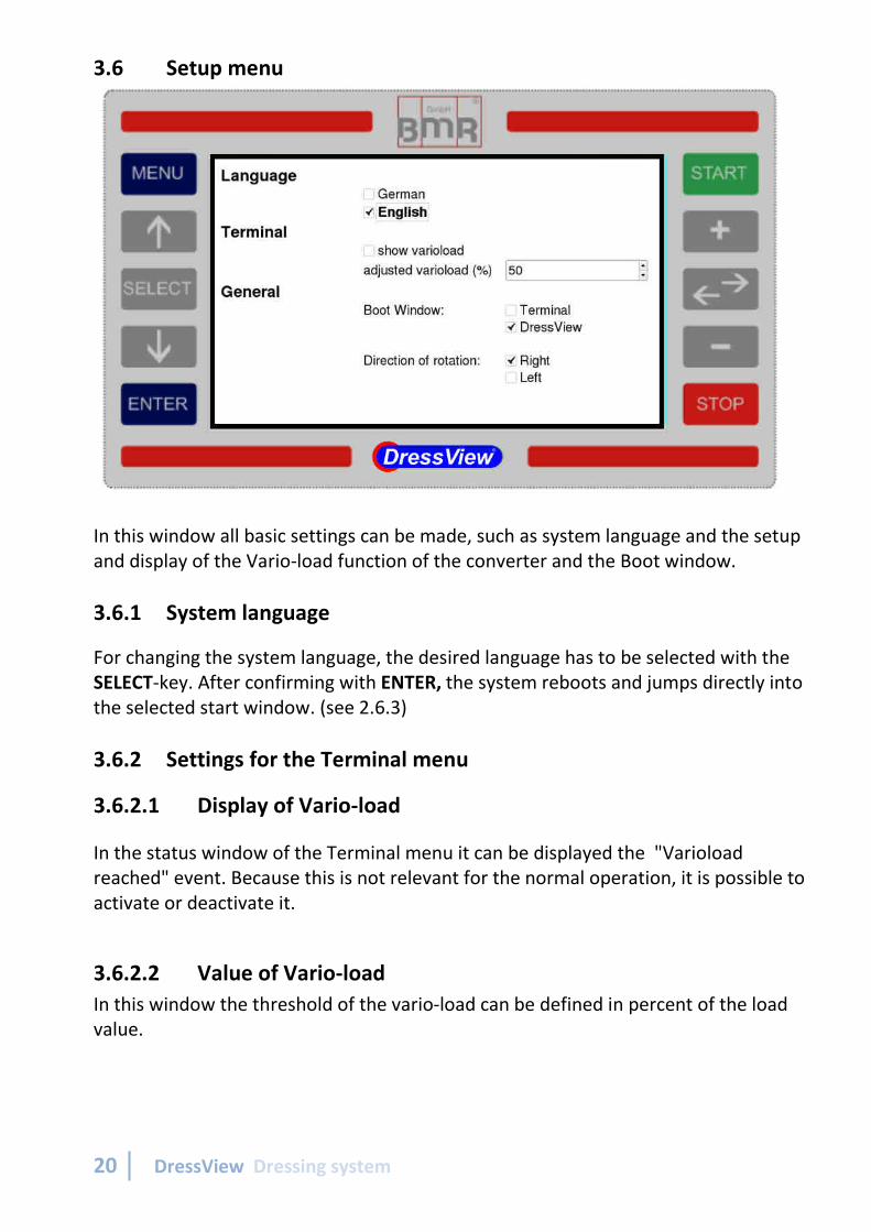
3.6 Setup menu
In this window all basic setting
and display of the Vario-load function of the conver
3.6.1 System language
For changing the system language, the desired language has to be selected with the
SELECT-key. After confirming with
the selected start window.
3.6.2 Settings for the
3.6.2.1 Display of Vario
In the status window of the Terminal menu it can be displayed the "Varioload
reached" event. Because this is
activate or deactivate it.
3.6.2.2 Value of Vari
In this window the threshold of the vario
value.
Dressing system
In this window all basic settings can be made, such as system language and
oad function of the converter and the Boot
System language
For changing the system language, the desired language has to be selected with the
After confirming with ENTER, the system reboots and jumps
the selected start window. (see 2.6.3)
ngs for the Terminal menu
Vario-load
In the status window of the Terminal menu it can be displayed the "Varioload
eached" event. Because this is not relevant for the normal operation, it is possible to
Vario-load
In this window the threshold of the vario-load can be defined in percent of the load
can be made, such as system language and the setup
Boot window.
For changing the system language, the desired language has to be selected with the
the system reboots and jumps directly into
In the status window of the Terminal menu it can be displayed the "Varioload
not relevant for the normal operation, it is possible to
load can be defined in percent of the load

…when it comes to quality! BMR GmbH 21
3.6.3 General settings
3.6.3.1 Boot window
specifies into which start window should be booted after power on.
• Terminal - window: For manual operation
• DressView - window: is suitable, in case if the device is operated in the
controlled mode and it should be used with same settings as before. By this an
automatic operation with a PLC is possible.
3.6.3.2 Direction of rotation
Here it is determined the direction of rotation of the spindle. If the rotational
direction is set via a digital input, the direction which is selected in this window is
overridden.
3.6.3.3 Update
When choosing "Update" the software reboots itself and searchs for an attached
update-qualified USB stick which contains a firmware newer than the device itself.
If an update-qualified USB stick is detected, a message box appears, which shows the
version date of the newer firmware as well as the version date of the device.
Now there is the option to cancel this message box with pressing "ENTER" or
choosing "OK" with pressing "SELECT", "Arrow up" or "Arrow down". As soon as "OK"
is chosen and "ENTER" is pressed, the update process starts. After having finished.
the software immediately restarts with the newer firmware.
Update-qualified USB stick and Firmware
A preconfigured and update-qualified USB stick with the latest firmware can be
ordered by BMR on a charge.
As a second option there is the possibility to create an own update-qualified USB stick.
This stick has to fulfill the following criteria:
Name: BMR
File format: ext2, ext3, ext4 or MS-DOS-FAT
In general, the latest firmware is available by BMR on request. It can be downloaded
and copied on an USB stick, which can plugged into the USB jack on the back of the
desktop device or direct at the DressView Operating Terminal.

22 DressView Dressing system
4 Use of the system in the drilling / milling
Additionally to dressing applications, the system can also be used very easily in other
applications, such as automated drilling and milling. The resulting benefits are, that
the current signal of the regulation value can steadily be compared to a nominal
value.
So, for example, the detection of tools getting dull or having reduced sharpness can
be detected very early. This would result in an increase of the regulation value in
comparison to the value of the sharp state. This gives the chance to notify the
operator to change the tool before the quality of the surface gets too bad or the tool
breaks.
Another possibility is the detection of broken tool, because here is the value
significantly low during operation. So in this case the automated process can be
interrupted immediately, and it is not wasted time while working without tool.
For this purpose also the dressing menu must be called and the "in blocks" or
"controlled" display mode can be set.

…when it comes to quality! BMR GmbH 23
5 DressView ®-specific inputs and outputs
The DressView ® specific interface is located on the back panel of DressView 0200 or
DressView 0303 and on the front panel of DressView SSE.
It is realized with a pluggable screw terminal. It's functions are described in 2.4.2.2
PIN Function Decription Type
GND Ground
Digital IN 1 Dressing startstarts drawing the regulation value into
the dressing graph in "Controlled" mode0-24V
Digital IN 2 Zeroing Zeroing or Calibration of the system 0-24V
Digital IN 3 Spindle start Start spindle in Dressing menu 0-24V
Digital OUT 3 Dressing resultdelivers depending on usage a result for
cutting detection or for dressing
Open Collector-output
45V/0,5A
Digital OUT 2 LimitDelivers a HI-signal when exceeding the
trigger level during activated dressing
Open Collector-output
45V/0,5A
Digital OUT 1 ReadyIndicates, if the system is ready or if it is
on error
Open Collector-output
45V/0,5A
Analog OUTRegulation
value
Analogue value, corrosponding to the
graph line in the dressing window0…10V
GND / Uh Ground or auxilary voltage on option 12V / 20mA
� Switch level of digital inputs: "0" = 0…7V / "1" = 18….24V PLC Standard Level
� Voltage range analogue output: 0…10V
Important:
When the spindle is started via the digital input IN3, it is no longer possible to stop
the spindle via the slide keys. A stop can then only be triggered by a corresponding
level change to IN 3.
1 2 3 4 5 6 7 8 9

24 DressView Dressing system
6 USB-Interface
Each DressView device (SSE or Deskto
built-in or connected inverter can be configured directly by PC (SFU
If a PC is connected via USB, the following message appears on the display of
DressView:
"PC-connection detected. DressView i
As long as this connection exists
all functions are available, immediately.
7 Connection
The sketch shown in section 3.4.2.2 may be used as an example
for connecting.
7.1 Connecting the SSE
Besides the integrated desktop versions, the system is available as
separated solution for cabinet mounting, also. It consists of the
DressView SSE unit and the Operating Terminal, which have to be
connected with a specific
the power supply. The DressView SSE
interface between the machine, BMR converter and DressView
Operating Terminal.
SFU I/O: looped through digital an
the connected SFU0200
To connect a PC to the SFU0200 you have to use the
USB-interface.
SFU 0200: Connection port to SFU0200
SFU 0303: RS232 Connection plug for connecting the SFU0303
DressView OT: Plug for the connec
Operating Terminal
I/O Interface: Interface as specified in section 5.
USB: Communication interface to BMR
for configuration with SFU
Power supply: 24VDC 2.5A
Dressing system
Each DressView device (SSE or Desktop) always includes an USB Interface.
connected inverter can be configured directly by PC (SFU
If a PC is connected via USB, the following message appears on the display of
connection detected. DressView is not active while a PC is connected."
connection exists, the dressing system is inactive. After disconnection,
immediately.
The sketch shown in section 3.4.2.2 may be used as an example
Connecting the SSE -System
Besides the integrated desktop versions, the system is available as
separated solution for cabinet mounting, also. It consists of the
unit and the Operating Terminal, which have to be
cable which carries all data signals and
. The DressView SSE acts as the communication
interface between the machine, BMR converter and DressView
looped through digital and analog In- and outputs of
nnected SFU0200. RS232 is no longer available.
To connect a PC to the SFU0200 you have to use the
interface.
Connection port to SFU0200
RS232 Connection plug for connecting the SFU0303
Plug for the connection cable to the DressView
Operating Terminal
Interface as specified in section 5.
Communication interface to BMR-frequency converter
for configuration with SFU-Terminal on PC.
24VDC 2.5A
USB Interface. By this the
connected inverter can be configured directly by PC (SFU-Terminal).
If a PC is connected via USB, the following message appears on the display of
s not active while a PC is connected."
, the dressing system is inactive. After disconnection,
Besides the integrated desktop versions, the system is available as
separated solution for cabinet mounting, also. It consists of the
unit and the Operating Terminal, which have to be
ta signals and
the communication
interface between the machine, BMR converter and DressView
and outputs of
. RS232 is no longer available.
To connect a PC to the SFU0200 you have to use the
to the DressView
frequency converter

…when it comes to quality! BMR GmbH 25
8 Delivery contents
The DressView® system from BMR works only with frequency converters from BMR
and dressing spindles in a mounting range from 33mm to 72mm.
It is always supplied as a unit consisting of the DressView unit and a dressing spindle.
For that reason it is necessary to specify the desired spindle size and also the type of
dressing tool with an order.

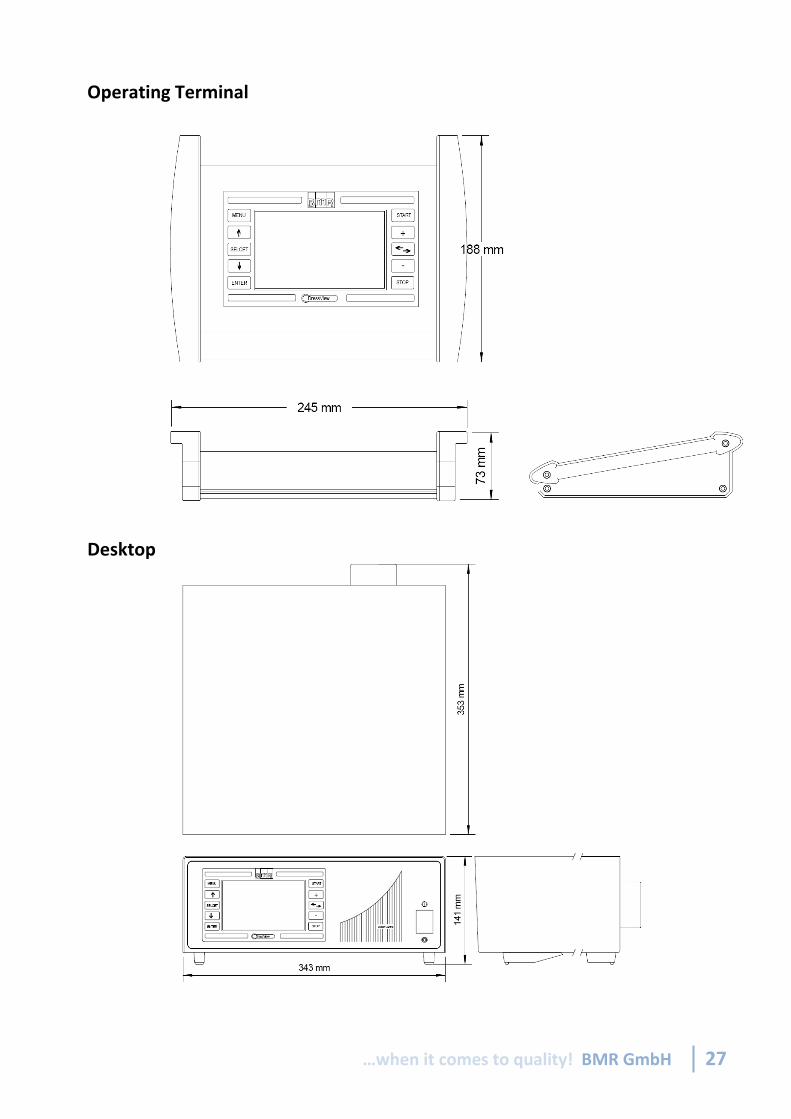
26 DressView Dressing system
9 Dimensions and Mounting
SSE
…when it comes to quality! BMR GmbH 27
Desktop
Operating Terminal

28 DressView Dressing system
OUR QUALITY COMMITMENT
100% „Made in Germany“
100% precision
100% reliability
100% support
100% flexibility
Subject to technical alterations.
June 2017

…when it comes to quality! BMR GmbH 29

30 DressView Dressing system