
DREDGE SYSTEMS - irp-cdn.multiscreensite.com · VORTEX INTERNATIONAL - Vortex 2.5-inch Operations...
25
2.5-INCH ROV DREDGE EQUIPMENT OPERATIONS MANUAL PATENTS PENDING DREDGE SYSTEMS All information correct as of August 2012 and subject to change without notice
-
Upload
nguyenhanh -
Category
Documents
-
view
214 -
download
0
Transcript of DREDGE SYSTEMS - irp-cdn.multiscreensite.com · VORTEX INTERNATIONAL - Vortex 2.5-inch Operations...

2.5-INCH ROV DREDGEEQUIPMENT OPERATIONS MANUAL
PATENTS PENDING
DREDGE SYSTEMS
All information correct as of August 2012 and subject to change without notice

2.5-INCH ROV DREDGEEQUIPMENT OPERATIONS MANUAL
2 VORTEX INTERNATIONAL - Vortex 2.5-inch Operations Manual - www.vortexdredge.com
ContentsIntroduction ................................................................................................................................................................................ 3
Operating Limits .......................................................................................................................................................................... 4
Risks - Normal Operations ........................................................................................................................................................... 4
Safety ......................................................................................................................................................................................... 4
Vortex 2.5-inch Introduction ........................................................................................................................................................ 4
Vortex 2.5-inch Dredge Capacity ................................................................................................................................................. 5
Main Components Weights and Measures ................................................................................................................................... 6
User Checklist BEFORE Dive ......................................................................................................................................................... 7
User Checklist AFTER Dive .......................................................................................................................................................... 8
Vortex 2.5-inch Hydraulics ........................................................................................................................................................... 9
Pump and Motor ......................................................................................................................................................................... 9
Pipe Work ................................................................................................................................................................................... 9
Pressure Hose ............................................................................................................................................................................. 9
Suction Hose and Handle ............................................................................................................................................................. 9
Schematics Drawings ................................................................................................................................................................. 10
Vortex 2.5-inch Hydraulics ......................................................................................................................................................... 11
Vortex 2.5-inch Hydraulic Hoses ................................................................................................................................................ 11
Installation - Component Placement ......................................................................................................................................... 12
Installation ................................................................................................................................................................................ 14
Installation - Frame Configuration .............................................................................................................................................. 15
Installation - Water Pump Remote Mounted Individually ............................................................................................................. 16
Installation - Hose Connections ................................................................................................................................................. 18
Installation - Flotation .............................................................................................................................................................. 20
Spare Components .................................................................................................................................................................. 21
Shipping Box and Correct Stowage of Components ................................................................................................................... 22
Trouble Shooting ..................................................................................................................................................................... 23

2.5-INCH ROV DREDGEEQUIPMENT OPERATIONS MANUAL
VORTEX INTERNATIONAL - Vortex 2.5-inch Operations Manual - www.vortexdredge.com 3
Introduction
These new systems have been manufactured from 316 Stainless Steel to reduce corrosion and time consuming maintenance
requirements.
This powerful ROV operable dredging system is easy to install and operate from most electric ROV.
The Vortex ROV 2.5-inch is designed for Subsea excavation and disposal of seabed materials up to 59 millimetres in size. It can be
mounted to any Work Class ROV and requires no ship deck space and sea fastening.
The Vortex 2.5-inch is very powerful, has no depth limitations and is quick and easy to mobilize and operate, it can also be run in
air.
The Vortex 2.5-inch equipment can be operated and maintained by the ROV crew, however it is advised Vortex personnel be
involved in the initial set up and testing phase on each operation.
Vortex has developed a dredge kit with two primary considerations:
First priority is ease of mobilization. The client needs to see rapid deployment of hire gear. We have included a comprehensive
range of the many brackets and fixtures the ROV operator commonly has to manufacture whilst offshore. Flotation is supplied as
standard kit, again alleviating the need to source suitable buoyancy. The entire kit is shipped in one single box.
Wear components are replaceable and manufactured from very high grade, wear resistant stainless steel.
Your safety is your responsibility. Please ask if you are unsure about anything.

2.5-INCH ROV DREDGEEQUIPMENT OPERATIONS MANUAL
4 VORTEX INTERNATIONAL - Vortex 2.5-inch Operations Manual - www.vortexdredge.com
Operating LimitsThe operating limit for the Vortex 2.5-inch, will be the responsibility of the Senior ROV person on-site. The limitation being the
ability to safely deploy and recover the ROV system with the Vortex 2.5-inch attached. Care must be taken whilst during launch
and recovery operations to prevent damage to all components of the dredge system and the ROV.
Risks - Normal OperationsAll personnel involved in deck operations shall be aware of the potential risk described hereafter.
• Crane handling (possible danger of e.g. heavy falling object)
• Launch and recovery of equipment over the side of the vessel
• Personnel working over open sea (typical personnel working with launch and recovery of equipment from
vessel deck or moon pool)
• Object falling down from height (rocks following the equipment when recovering)
• Working with equipment under pressure (hydraulics or water)
• Hydraulic oil spillage
SafetyPersonal protection equipment recommended for use when working on ship/platform deck.
• Hard hat
• Safety glasses
• Gloves
• Safety boots
• Overall
Vortex 2.5-inch IntroductionThe Vortex 2.5-inch is designed for Subsea excavation and disposal of sediments and gravel up to 59 millimetres. It is easily
mounted to the ROV and requires no ship deck space and sea fastening. The Vortex 2.5-inch requires no specialist operator or
additional cables between ship and sea floor.

2.5-INCH ROV DREDGEEQUIPMENT OPERATIONS MANUAL
VORTEX INTERNATIONAL - Vortex 2.5-inch Operations Manual - www.vortexdredge.com 5
The Vortex 2.5-inch is characterized by the following advantages:
• No depth limitations
• Quick mobilization
• Easy operation
The Vortex 2.5-inch equipment is easy to set up and use. However, if on site support is agreed in the contract, Vortex personnel
will assist during mobilization and demobilization and or support the project during the entire operation.
Vortex 2.5-inch Dredge Capacity
Removal rates based on actual material moved during testing using Magnetite black iron sand and
rocks weighing 2.375 kg per litre
• 6.8 ton / hr - using 15 lpm (3.9 gpm) and 140 bar (2030 psi)
• 4.5 cubic meter / hr - using 15 lpm (3.9 gpm) and 140 bar (2030 psi)
• 6% solids by volume
• Suction capabilities
= 58 kpa (17.1in/hg) using 15 lpm (3.9 gpm) and 140 bar (2030 psi)
• Minimum hydraulic supply required
= 15 lpm (3.9 gpm) and 140 bar (2030 psi)
• Hydraulic hoses supplied:
pressure and return = 3 mtr long, 4250 psi (293 bar) rated. -8 jic female swivel ends
case drain = 3 mtr long, 1000 psi (68 bar), -6 jic female swivel ends
• Complete kit in box = 260 kg, 930 mm high x 1000 mm wide x 1600 mm long
• Water pump weight in air = 40 kg
• Water pump weight in water = 38 kg
• Suction hose diameter = 50 mm
• Actual internal dredge diameter = 59 mm
• Potential debris diameter = 56 to 58.5 mm
• Weight of optional aluminum pump frame
= 9 kg, 600 mm high x 420 mm wide x 700 mm long

2.5-INCH ROV DREDGEEQUIPMENT OPERATIONS MANUAL
6 VORTEX INTERNATIONAL - Vortex 2.5-inch Operations Manual - www.vortexdredge.com
Main Components Weights and Measures
Pump weight in air 40 kg (complete pump unit)
Pump weight in water 38 kg (complete pump unit)
Venturi 6 kg
Water pump to Venturi U bend 6 kg
Bungee cord and carabiner n/a
Cargo straps 1 kg each (5 units)
Exhaust hose 6 kg
Frame 6 kg
Hydraulic hoses 6 kg
Inlet hose 12 kg
Shipping box 260 kg full and ready to ship
Spare gaskets n/a
Spare hose clamps 1 kg
Saddle clamp 1 kg each (2 units)
Brackets to mount pump 0.5 kg (2 units)
Water pump outlet 45 degree bend 2 kg
Spare cam locks 1 kg (2 units)
2.5-inch water pump to Venturi hose 4 kg
Manuals n/a
Buoyancy of flotation combination Buoyancy = 1000 mtr or 3000 mtr optional
VORTEX remote pump inlet filter kit 1x flange with straight pipe, 1 x flange with 90 degree bend,
1 x 4 inch hose section.
VORTEX pump spares kit with spare over run check valve CXFA-XAN.
All items must be accounted for upon return to avoid damage / loss charges.

2.5-INCH ROV DREDGEEQUIPMENT OPERATIONS MANUAL
VORTEX INTERNATIONAL - Vortex 2.5-inch Operations Manual - www.vortexdredge.com 7
User Checklist BEFORE Dive
To prevent any damage to the equipment this checklist must be followed
Project: ............................................................................................................... Dredge No: ................................................................................................
Item Description Checked Comments Date
1 Ensure ROV can and does supply 14 lpm
@ 140 bar before fitting dredge kit
Follow hose directions as shown
2 All fittings are checked for leakage
3 All hose clamps are checked
4 Pumps are fastened, no loose screws
5 Suction hose is fastened
6 Dredge is fastened, no loose ends
7 All hoses are fastened and in proper condition
8 Filter for induction is mounted
9 No hoses are squeezed or bent
10 Inlet nozzle is mounted correctly
11 Case drain and coupling are filled
with clean oil
Comments: ...............................................................................................................................................................................................................................................
............................................................................................................................................................................................................................................................................
............................................................................................................................................................................................................................................................................
Dredge is checked by: ........................................................................................................ Date: ...........................................................................................
2.5-INCH ROV DREDGEEQUIPMENT OPERATIONS MANUAL
8 VORTEX INTERNATIONAL - Vortex 2.5-inch Operations Manual - www.vortexdredge.com
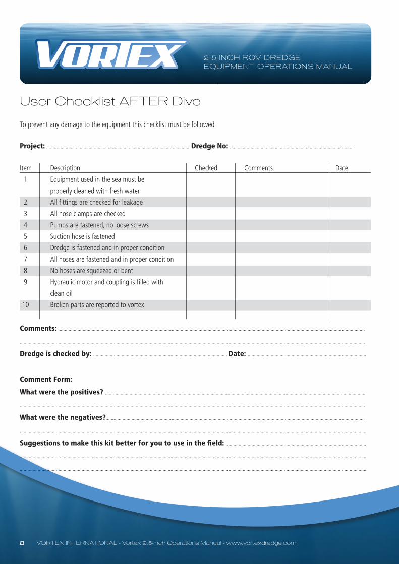
User Checklist AFTER Dive
To prevent any damage to the equipment this checklist must be followed
Project: ............................................................................................................... Dredge No: ................................................................................................
Item Description Checked Comments Date
1 Equipment used in the sea must be
properly cleaned with fresh water
2 All fittings are checked for leakage
3 All hose clamps are checked
4 Pumps are fastened, no loose screws
5 Suction hose is fastened
6 Dredge is fastened and in proper condition
7 All hoses are fastened and in proper condition
8 No hoses are squeezed or bent
9 Hydraulic motor and coupling is filled with
clean oil
10 Broken parts are reported to vortex
Comments: ..............................................................................................................................................................................................................................................
............................................................................................................................................................................................................................................................................
Dredge is checked by: ........................................................................................................ Date: ............................................................................................
Comment Form:
What were the positives? ..........................................................................................................................................................................................................
............................................................................................................................................................................................................................................................................
What were the negatives?.........................................................................................................................................................................................................
.............................................................................................................................................................................................................................................................................
Suggestions to make this kit better for you to use in the field: .............................................................................................................
.............................................................................................................................................................................................................................................................................
.............................................................................................................................................................................................................................................................................

2.5-INCH ROV DREDGEEQUIPMENT OPERATIONS MANUAL
VORTEX INTERNATIONAL - Vortex 2.5-inch Operations Manual - www.vortexdredge.com 9
Vortex 2.5-inch Hydraulics
Hose Connectors1/2” Pressure Hydraulic Hose -8 JIC Female fittings
1/2” Return Hydraulic Hose -8 JIC Female fittings
3/8” Case Drain Hydraulic Hose -6 JIC Female fittings
Hydraulic Motor Requirements (minumum)Capacity / Pressure: 14 litre per minute (3.9 gpm)
140 bar ( 2030 psi)
Vortex 2.5-inch Pump and MotorThe pump must be mounted on the ROV with ample room for both hydraulic and water hose connections.
Hydraulic connections seen at the top. Fill hydraulic motor with clean oil before start up.
Pump can also be run in air.
Vortex 2.5-inch Pipe WorkVortex pipe-work with cam locks for suction hose and pressure hose (left) and exhaust tube (right). The pipe work is easily
fixed to the ROV using cargo straps or ropes.
Vortex 2.5-inch Pressure HosePressure hose between pipe-work and pump. Inlet filter for pump flexible hoses to simplify assembly and placement of
equipment on the ROV.
Suction Hose and HandleThe suction head comes equipped with a fish-tail style handle for ROV manipulator. Other handle versions can be supplied.

2.5-INCH ROV DREDGEEQUIPMENT OPERATIONS MANUAL
10 VORTEX INTERNATIONAL - Vortex 2.5-inch Operations Manual - www.vortexdredge.com
Schematics Drawing Vortex 2.5-inch
To facilitate mobilization times, the water pump hydraulic motor has an ‘over spin’ valve fitted as standard equipment so ROV crew do not need to find or adapt a check valve .‘Reverse flow’ of hydraulic fluid through the motor will result in water pump not working, but will not damage components as hydraulic fluid will flow through ‘over spin’ valve back to tank.Important - ensure motor case is filled with clean oil before start up. Failure to do this can cause hydraulic motor failure. Always ensure a high standard of cleanliness when connecting and disconnecting hoses and couplings.
HYDRAULIC SUPPLY (Minimum):14 litre per minute (3.9 gpm)
140 bar ( 2030 psi)
Maximum of 4000psi (275BAR)

2.5-INCH ROV DREDGEEQUIPMENT OPERATIONS MANUAL
11 VORTEX INTERNATIONAL - Vortex 2.5-inch Operations Manual - www.vortexdredge.com
2.5-inch Performance Graph

2.5-INCH ROV DREDGEEQUIPMENT OPERATIONS MANUAL
VORTEX INTERNATIONAL - Vortex 2.5-inch Operations Manual - www.vortexdredge.com 12
Vortex 2.5-inch Hydraulics
Hydraulic Schematics
Vortex 2.5-inch Hydraulic Hoses
Hydraulic hoses for pump/motor connections.
Two 3 mtr lengths 1/2’ hoses
One 3 mtr length 3/8”
Weight approx. 6 kg Hydraulic hoses 3 mtr long each.4250 psi (293 bar) pressure rating.-8 jic Pressure, -8 jic tank, -6 jic case drain.

2.5-INCH ROV DREDGEEQUIPMENT OPERATIONS MANUAL
13 VORTEX INTERNATIONAL - Vortex 2.5-inch Operations Manual - www.vortexdredge.com
Installation - Component Placement
WATER PUMP IN FRAME OPTION:This illustration depicts only one of many combinations that may be used to mount the water pump onto the ROV utilizing the supplied frame.If needed, the supplied buoyancy should be placed where it would be most effective to balance the weight of the dredge components to achieve neutral pitch and roll of the ROV when submerged.

2.5-INCH ROV DREDGEEQUIPMENT OPERATIONS MANUAL
VORTEX INTERNATIONAL - Vortex 2.5-inch Operations Manual - www.vortexdredge.com 14
Installation - Component Placement
Modular system shown for various installation methods

2.5-INCH ROV DREDGEEQUIPMENT OPERATIONS MANUAL
VORTEX INTERNATIONAL - Vortex 2.5-inch Operations Manual - www.vortexdredge.com 15
Installation - Component Placement
Venturi will often fit inside ROV frame, greatly increasing A-Frame launching clearance.
Simple fast and secure installation options. Supplied, pre-made pump brackets greatly reduce mobilization time.
WATER PUMP MOUNTED AWAY FROM VENTURI INSTALLATION:This illustration depicts only one of many combinations that may be used to mount the water pump onto the ROV independently of the Venturi by using the supplied brackets, cargo straps and pipe clamps.Installation should have as few bends in hoses as possible.If needed, the supplied buoyancy should be placed where it would be most effective to balance the weight of the dredge components to achieve neutral pitch and roll of the ROV when submerged.

2.5-INCH ROV DREDGEEQUIPMENT OPERATIONS MANUAL
16 VORTEX INTERNATIONAL - Vortex 2.5-inch Operations Manual - www.vortexdredge.com
Installation
Cargo straps for general tie backs of hoses and mounting of Venturi to ROV frame if need be.Weight = 0.5 kg each
Bungee cord with carabiner used to tie back inlet hose on ROV frame and allow movement of inlet hose.Weight = N/A
Frame to mount water pump and Venturi. Bolt frame complete with water pump and Venturi directly to ROV frame, or strip components to mobilize as location allows.Weight = 6 kg Dimensions = 420 mm wide x 700 mm long x 600 mm high
Optional water jetter: Uses water taken from the water pump outlet and shown in tests not to affect dredge suction performance. Included in kit, ‘slip-on’ jetter head goes on end of suction inlet, diverter valve, hydraulic hoses.

2.5-INCH ROV DREDGEEQUIPMENT OPERATIONS MANUAL
17 VORTEX INTERNATIONAL - Vortex 2.5-inch Operations Manual - www.vortexdredge.com
Installation - Water Pump Remote Mounted Individually
Water pump shown with hydraulic hose marking tags. Hydraulic motor is fitted with over spin valve as standard equipment.Coupling has been engineered to operate without external compensator to avoid oil leakage. Water pump shown with 90 degree water outlet. Also supplied is a 45 degree water outlet. Both outlets have multi-position bolt holes to facilitate installation in ROV frame. Water pump with hydraulic hose marking tags for easy identification and mobilization.
Water pump shown mounted on brackets supplied as optional method for mounting on ROV frame.Weight = 40 kg in airWeight = 38 kg in water
Water pump mounted on generic brackets and motor ‘over spin’ valve block mounted on hydraulic motor.
Brackets to mount water pump generically to ROV frame.Weight = 0.5 kg Dimensions = 500 mm x 40 mm x 40 mm

2.5-INCH ROV DREDGEEQUIPMENT OPERATIONS MANUAL
VORTEX INTERNATIONAL - Vortex 2.5-inch Operations Manual - www.vortexdredge.com 18
Installation - Hose Connections
Water pump to Venturi hose cam locks for generic ROV installation. Field fit on supplied hose between water pump and Venturi use when mounting water pump and Venturi separately on ROV frame.Weight = 1 kg each
Water pump to Venturi hose for field fitting during generic ROV installation.Weight = 3 kg Length = 2500 mm
Venturi 2.5-inchWeight = 6 kg Length overall = 615 mm
INLET FROMWATER PUMP
VENTURI INLET / SUCTION
VENTURIEXHAUSTOUTLET

2.5-INCH ROV DREDGEEQUIPMENT OPERATIONS MANUAL
19 VORTEX INTERNATIONAL - Vortex 2.5-inch Operations Manual - www.vortexdredge.com
Installation - Hose Connections
Inlet and exhaust 4-inch hose bends for routing inlet and exhaust hoses.45 degree = 0.75 kg each 90 degree = 1 kg each
Inlet hose with suction head and ROV manipulator handle. Operator can ‘tape’ on depth markings in 200 increments. Clip hose onto Venturi and attach to ROV using bungee cord or rope as required.Weight = 9 kg Length = 3500 mm
Hydraulic hose fitted with clear markings to facilitate mobilization times.Pressure and return hoses have identical pressure rating to avoid chance of failure through incorrect assembly.
Vortex water pump “Remote” mounting inlet filter flanges. Use to mount inlet filter in CLEAN water to avoid pump damage.

2.5-INCH ROV DREDGEEQUIPMENT OPERATIONS MANUAL
VORTEX INTERNATIONAL - Vortex 2.5-inch Operations Manual - www.vortexdredge.com 20
Installation
Installation - Hose Connections
Pipe clamps to secure Venturi to frame and generically to ROV frame. Remove from frame and use to mount Venturi as desired. Weight = 1 kg each
Exhaust hose fitted to rear of Venturi.Weight = 6 kg Length = 1700 mm
One example of water pump placement.
Water pump remote inlet filter option.
Water pump remote inlet filter option placed in “clean water” area away from sand.
One example of Venturi placement.

2.5-INCH ROV DREDGEEQUIPMENT OPERATIONS MANUAL
21 VORTEX INTERNATIONAL - Vortex 2.5-inch Operations Manual - www.vortexdredge.com
Installation - Flotation
Flotation shown mounted on top of frame. Blocks can be secured with threaded rod or rope lashing using holes provided in blocks and aligning holes in frame.
Flotation blocks measure approximately 680 mm long x 400 mm wide x 110 to 170 mm high for varying options of buoyancy.
1000 mtr Flotation blocks or optional 3000 mtr Flotation blocks.
(Note: Flotation blocks may differ from kit to kit)
Flotation shown mounted on side of frame. Blocks can be mounted on either side or top of frame to suit application or mount blocks to ROV where convenient.

2.5-INCH ROV DREDGEEQUIPMENT OPERATIONS MANUAL
VORTEX INTERNATIONAL - Vortex 2.5-inch Operations Manual - www.vortexdredge.com 22
Spare Components
Vortex pump spares kit.Spare exhaust cone.

2.5-INCH ROV DREDGEEQUIPMENT OPERATIONS MANUAL
23 VORTEX INTERNATIONAL - Vortex 2.5-inch Operations Manual - www.vortexdredge.com
Shipping Box and Correct Stowage of Components
Shipping box: Weight = 120 kg empty, 392 kg fullDimensions = 1000 mm wide x 1600 mm long x 930 mm high
Forklift slots fitted to alleviate need for certified lifting points. No protrusions from box reduce risk to box and surrounding equipment. Lockable at two points. Aluminium construction for lightweight.
NOTE: It is the field crew’s responsibility to ensure the correct placement of components in box prior to return to avoid incurring damage / loss costs.
Full kit shown in shipping box as deployed. The entire kit is in one shipping box for ease of deployment.
PLEASE RE- ASSEMBLE ALL COMPONENTS AS FOUND TO ENSURE SAFE SHIPPING TO BASE.FAILURE TO DO SO MAY INCUR DAMAGE COSTS.
Above photo shows placement of components for shipping.Please ensure kit is packed away correctly.

2.5-INCH ROV DREDGEEQUIPMENT OPERATIONS MANUAL
VORTEX INTERNATIONAL - Vortex 2.5-inch Operations Manual - www.vortexdredge.com 24
Trouble Shooting
Symptom: Water pump not operatingRemedy:
1. Ensure that the hydraulic hoses are connected as per manual drawings and match connection labels.
2. Check that 14 lpm at 140 bar can be seen directly at the Vortex water pump hydraulic motor.
3. Check any quick connect fittings you may have in the circuit as they can sometimes be faulty.
4. Are your thrusters using most of the available system flow and starving your circuit feeding the Vortex water pump?
5. Ensure the Vortex case drain is connected directly to tank. It is preferable to connect as close as possible to the
reservoir and not run any hoses through quick connects.
6. Has the water pump impeller been damaged by excessive silt or other dirt ingress? If so, please repair as
necessary with accordance to supplied Vortex pump servicing handbook.
7. Check that the over spin valve is operating correctly and does not have dirt ingress causing fluid to bypass the
check valve. Replace with SUN valve, part number HCV 2743 as necessary.
Symptom: Debris removal slowRemedy:
1. Check the caged nozzle of inlet hose is not blocked. Stop hydraulic flow to water pump to allow rocks and
debris to be cleared.
2. Check that all cam locks are fastened and secured correctly.
3. Check all cam lock o-rings are in place and in good condition.
4. Use steady and consistent movements when plunging suction hose inlet into seabed. Try side to side and up and
down movements of suction hose inlet. Differing conditions may require changing methods.
5. Check all hydraulic remedies as seen in “water pump not operating” section of trouble shooting.
6. Check inlet and exhaust hoses are not bent or blocked.

Joe Goodin - Managing Director VORTEX International Ltd, 27 Parrs Road, RD1, New Plymouth, New ZealandTel/Fax: +64 (6) 753 8102, Mobile: +64 (0) 27 688 5372Email: [email protected], www.vortexdredge.com
In association with Ashtead Technology:
ABERDEENAshtead Technology LtdAshtead House, Discovery Drive, ArnhallBusiness Park, Westhill, Aberdeenshire AB32 6FGTel: +44 (0)1224 771888, Email: [email protected]
SINGAPOREAshtead TechnologyLoyang Offshore Supply Base, 25 Loyang Crescent, Block 302, Unit 02-12 TOPS Ave 3, PO Box 5157, SINGAPORE 508988Tel: +65 6545 9350, Email: [email protected]
HOUSTONAshtead Technology Inc, 19407 Park Row, Suite 170, Houston, TX 77084, U.S.ATel: +1 281 398 9533, Fax: +1 281 398 3052, Email: [email protected]
SCOPE ENGINEERING (Ashtead Technology Agent)Scope Engineering (WA) Pty Ltd35 Stuart Drive, Henderson, Western Australia 6166T: +61 8 6498 9642 F: +61 8 6498 9584, Email: [email protected]
DREDGE SYSTEMS