
Draught Surveys - Second Edition
54
DRAUGHT SURVEYS A GUIDE TO GOOD PRACTICE Second Edition JIM DIBBLE, PETER MITCHELL and North of England P&I Association NORTH OF ENGLAND P&I ASSOCIATION
Transcript of Draught Surveys - Second Edition

Draught SurveySa guIDe tO gOOD PraCtICeSecond edition
JIM DIBBLe, Peter MItCheLL and North of england P&I association
NORTH OF ENGLAND P&I ASSOCIATION
JIM
DIB
BLe,
Pet
er M
ItCh
eLL
aND
NO
rth
OF
eNg
LaN
D P&
I aSS
OCI
atIO
N
Dra
ug
ht
Surv
eyS
Sec
ond
editi
onDraught SurveyS a guIDe tO gOOD PraCtICe Second edition
by JIM DIBBLe, Peter MItCheLL and North of england P&I association
The accurate measurement of dry bulk cargoes by a vessel can minimise considerably the risk of shortage claims and disputes. This guide outlines the methods and corrections for a draught survey to be carried out to the required accuracy. It is designed to help surveyors and recommends procedures and formulas for every circumstance likely to be encountered during the conduct of draught surveys. The UN ECE draught survey forms have been included in an effort to achieve standardisation throughout the industry.
Jim Dibble is a master mariner with 50 years experience in the shipping industry. He spent 12 years at sea as a deck officer and 31 years in the marine education department at South Tyneside College, where he led the development of the Marine Simulation Centre. He has since worked as a marine consultant and is currently UK managing director of Seagull Maritime Information Technologies Ltd.
Peter Mitchell is a master mariner with 40 years experience in the shipping industry, firstly as a deck officer and then as a senior lecturer in the marine department at South Tyneside College, UK. He is now retired.
North of England P&I Association has offices in the UK, Greece, Hong Kong and Singapore and is one of the leading international mutual marine liability insurers with over 100 million GT of entered tonnage. Founded in 1860, the Association has long recognised the importance of providing practical loss prevention advice to its members, believing this to be the most effective way to reduce the number and scale of claims. The Association has developed a world-wide reputation for the quality and diversity of its loss prevention initiatives, which include this series of loss prevention guides co-authored with industry experts.
NORTH OF ENGLAND P&I ASSOCIATION
£30ISBN: 978-0-9558257-5-0

Draught SurveySa guIDe tO gOOD PraCtICe Second edition
JIM DIBBLe, Peter MItCheLL and North of england P&I association
NORTH OF ENGLAND P&I ASSOCIATION
Authorised User (see Terms of Use): Member of North of England P&I Association
Dra
ught
Sur
veys
Originally published in 1994 and reprinted in 2005 by Mid-C ConsultancyISBN 0 9521164 1 3
Second edition published in 2009 by North of England P&I Association LimitedThe Quayside, Newcastle upon Tyne, NE1 3DU, United Kingdom
Telephone: +44 191 232 5221Fax: +44 191 261 0540Email: [email protected]: www.nepia.com
All rights reserved. No part of this publication may be reproduced, stored in a retrieval system or transmitted, in any form or by any means (electronic, mechanical, photocopying, recording or otherwise) without the written permission of the publisher.
Copyright © North of England P&l Association Limited 2009The Authors assert moral copyright in the work.
ISBN 978-0-9558257-5-0
Authors: Jim Dibble, Peter Mitchell and North of England P&l Association
Printed and bound in the UK
This publication is intended for general guidance only to assist in the conduct of a draught survey but it cannot apply to every situation. Readers should take care to ensure that the recommendations contained in this publication are appropriate for a particular situation before implementing them. Whereas every effort has been made to ensure that recommendations are comprehensive, North of England P&I Association and the authors do not under any circumstances whatsoever accept responsibility for any errors, omissions and mis-statements or for the consequences of implementing or attempting to implement the recommendations.
The authors would like to thank the following for their assistance: Commander T. Lilley of the International Institute of Marine Surveyors, Captain D. Green, Captain R. Ward, Captain P. Coombs and Captain Y. Aysuna.
Authorised User (see Terms of Use): Member of North of England P&I Association
CONTENTS
Chapter Page
1. INTRODUCTION 3
2. PRACTICAL PROCEDURE 4
3. INFORMATION REQUIRED 10
4. ASSESSMENT OF UNDERWATER VOLUME 15
5. DEDUCTIBLES 30
APPENDICES 35
I Glossary 35
II UN ECE draught survey code forms 37
III Equipment checklist 44
IV Information checklist 45
V Checklist of factors that may influence survey accuracy 46
VI Alternative hydrometer corrections 47
VII Corrections checklist 48
INDEX 49
Co
nte
nts
Authorised User (see Terms of Use): Member of North of England P&I Association
GUIDE TO USING ELECTRONIC VERSION1. Allbooksections,headingsandsubheadingsappearasbookmarks in the left-hand
navigationpane–usethisastheprimarynavigation.
2. Usethe‘FullAcrobatSearch’button(orCtrl+Shift+F)tosearchforalloccurrencesofawordorphraseinthetext(click‘ArrangeWindows’tofitallonscreen).
3. Clickontextwhichreferstoanotherpartofthebooktogothere,usetheAcrobat‘returntopreviouspageview’buttontogoback.
4. Manywordsorphrasesarelinkedtofurtherinformationinotherpartsofthebook(cursorchangestoahand)–clicktogothereandusetheAcrobat‘returntopreviouspageview’togoback.
5. Clickontextwhichreferstoanotherpublicationororganisationtogoitswebsiteviayourbrowser.ForIMOpublications,enterthetitle intotheIMOPublishing ‘Findproduct’box.
TERMS OF USEThispublicationmaybeusedsolelybytheAuthorisedUser.
TheAuthorisedUsershallcompriseanycompanyorindividual(oremployeesthereof)towhichNorthofEnglandP&IAssociationhasgrantedpermissiontousethispublication.
Anyotherunauthorisedmannerofexhibition,broadcastordistributionoftheinformation,form,contentorpresentationcontainedhereinandanypublicperformance,diffusion,editing,copying,reselling,hiringinwholeorinpart,isprohibited.
Authorised User (see Terms of Use): Member of North of England P&I Association
Chapter 1
INTRODUCTION
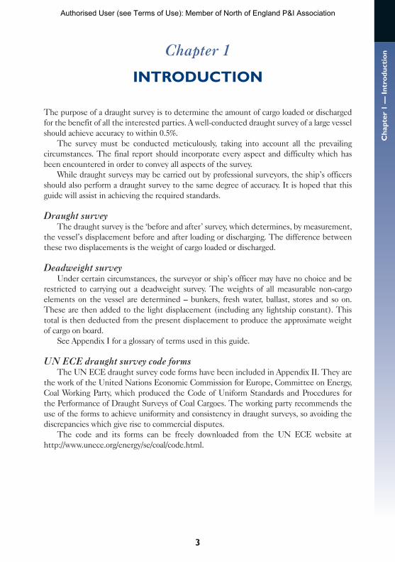
The purpose of a draught survey is to determine the amount of cargo loaded or discharged for the benefit of all the interested parties. A well-conducted draught survey of a large vessel should achieve accuracy to within 0.5%.
The survey must be conducted meticulously, taking into account all the prevailing circumstances. The final report should incorporate every aspect and difficulty which has been encountered in order to convey all aspects of the survey.
While draught surveys may be carried out by professional surveyors, the ship’s officers should also perform a draught survey to the same degree of accuracy. It is hoped that this guide will assist in achieving the required standards.
Draught surveyThe draught survey is the ‘before and after’ survey, which determines, by measurement,
the vessel’s displacement before and after loading or discharging. The difference between these two displacements is the weight of cargo loaded or discharged.
Deadweight surveyUnder certain circumstances, the surveyor or ship’s officer may have no choice and be
restricted to carrying out a deadweight survey. The weights of all measurable non-cargo elements on the vessel are determined – bunkers, fresh water, ballast, stores and so on. These are then added to the light displacement (including any lightship constant). This total is then deducted from the present displacement to produce the approximate weight of cargo on board.
See Appendix I for a glossary of terms used in this guide.
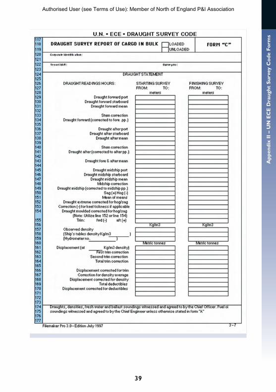
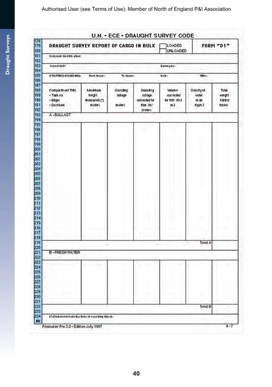
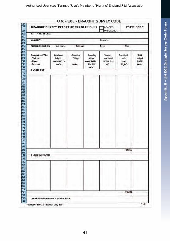
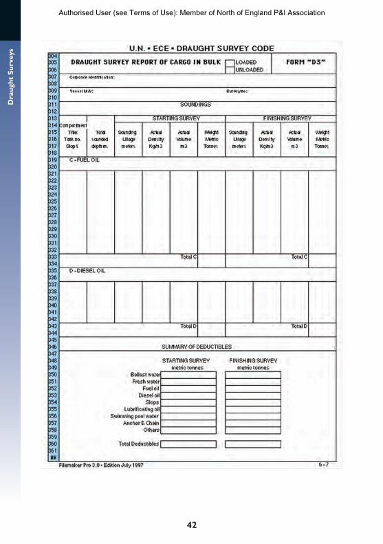
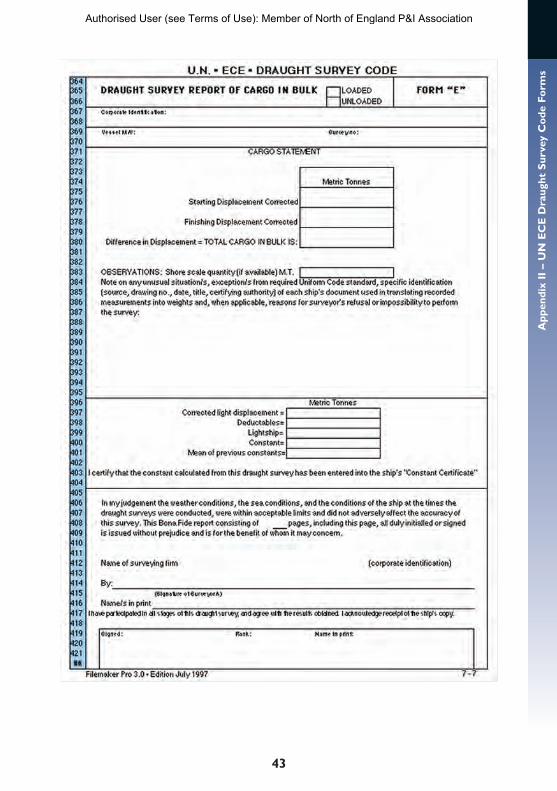
UN ECE draught survey code formsThe UN ECE draught survey code forms have been included in Appendix II. They are
the work of the United Nations Economic Commission for Europe, Committee on Energy, Coal Working Party, which produced the Code of Uniform Standards and Procedures for the Performance of Draught Surveys of Coal Cargoes. The working party recommends the use of the forms to achieve uniformity and consistency in draught surveys, so avoiding the discrepancies which give rise to commercial disputes.
The code and its forms can be freely downloaded from the UN ECE website at http://www.unece.org/energy/se/coal/code.html.
3
Cha
pter
1 —
Int
rodu
ctio
n
Authorised User (see Terms of Use): Member of North of England P&I Association
4
Dra
ught
Sur
veys Chapter 2
PRACTICAL PROCEDURE
It is impossible to cover every conceivable problem likely to be encountered when carrying out a draught survey. Ships and ports vary so much that there will always be the unforeseen circumstances which will require an on-the-spot decision. These notes and steps to be taken give only a broad approach to the subject. There is however no substitute for experience.
An inaccurate survey may result in considerable expense to several parties, therefore it should be conducted carefully and accurately. Being well prepared and having sufficient time will allow the survey to be conducted correctly. It may not appear expedient to delay the ship to complete the draught survey properly, but it could save money in the long term. This decision must lie with the master. However careful preparation could reduce delays to a minimum.
All parties should work together for a unanimous result. The facts should be established by inspection and not by verbal agreement.
STEPS TO BE TAKEN1. The ship and ship’s staff must be prepared for the survey. Shore surveyors must be ready for the ship’s arrival.
The ship should be asked to prepare for the draught survey.The ballast tanks should be adjusted to a level covered by the sounding tables. It should
be remembered that full tanks can be pressed up but still retain air pockets and also it can be difficult to establish that a tank is completely empty without visual inspection.
Ballast holds (main cargo holds used for ballast) should be empty of ballast on arrival at the loading port, if possible.
The vessel should arrive with a safe trim, suitable for navigation to enter port and within the limits of trim covered by the trim corrections of the sounding tables. The vessel should
arrive in an upright condition.Staff, documentation and equipment
should be ready on the arrival of the ship.
There should be no movement of ballast, fresh water, bunkers or cargo and hatches, cranes and moorings until all measurements are taken and agreed by surveyors and ship’s officers. The prudent surveyor will have observed the shore-side draughts before boarding as these can be used to indicate any changes.
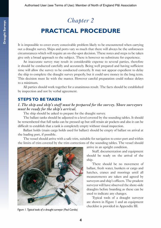
Typical tools of a draught surveyor are shown in Figure 1 and an equipment checklist is provided in Appendix III.
Figure 1. Typical tools of a draught surveyor (Paul Combs)
Authorised User (see Terms of Use): Member of North of England P&I Association
5
Ch
apte
r 2
– P
ract
ical
Pro
ced
ure
2. Examine the ship’s documentation and discuss the ship’s present conditionSurveyors and ship’s officers should discuss documentation details and the location
and state of all compartments. The instruction pages of the stability information book and calibration tables should be studied and a check made of the tank capacities with the capacity plan. It should be remembered that the port and starboard tanks may not be the same and consequently have separate calibration tables.
The base for measurement of vertical heights, the reference point for longitudinal measurements, the units and the sign conventions used in the tables must all be verified. The units used in the correction tables should also be carefully noted because there is sometimes a mixture of units and sign conventions contained within the same documentation. The calculations and corrections in this guide are all based on the metric units of metres and tonnes.
The full sounding depths of tanks, the summer draught and freeboard and the record of recent tank soundings should be noted.
If a bunker survey is not to be carried out, the chief engineer’s bunker figures (fuel oil, diesel oil and lubrication oil) are required, also the daily port consumption quantities. Should any bunkers or stores be delivered during the stay then the delivery notes must be sighted for the additional quantities to be included in the final survey. The draught survey only takes account of changes to the bunkers on board, that is consumption and deliveries.
The position of the anchors should be checked. Should any alterations be proposed during the stay then the weight of the anchors and cables should be determined.
The ship’s staff and surveyors should work together throughout. An information checklist is provided in Appendix IV.
3. Take accurate overboard water samples and draughtsDensity
Using a sample bucket take samples from half draught depths from at least two positions on the offshore and the onshore side, avoiding discharges, stagnant water between ship and jetty and outfall areas. Take samples of about one litre and do not mix the samples.
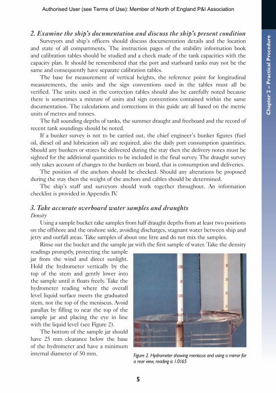
Rinse out the bucket and the sample jar with the first sample of water. Take the density readings promptly, protecting the sample jar from the wind and direct sunlight. Hold the hydrometer vertically by the top of the stem and gently lower into the sample until it floats freely. Take the hydrometer reading where the overall level liquid surface meets the graduated stem, not the top of the meniscus. Avoid parallax by filling to near the top of the sample jar and placing the eye in line with the liquid level (see Figure 2).
The bottom of the sample jar should have 25 mm clearance below the base of the hydrometer and have a minimum internal diameter of 50 mm. Figure 2. Hydrometer showing meniscus and using a mirror for
a rear view, reading is 1.0165
Authorised User (see Terms of Use): Member of North of England P&I Association
6
Dra
ught
Sur
veys
If densities obtained show no major variation then calculate the average value, however if there are suspicious variations in the readings then additional samples should be taken and this factor included in the report. Measure the apparent density with a suitable glass draught survey hydrometer, such as manufactured by Zeal, and be aware of any tidal changes which may affect the sample density (see density section in Chapter 4).
Draughts The draughts and densities should be obtained at nearly the same time if possible.
Draughts and densities taken at slack water are the most accurate but this may not be practicable.
All the draughts should be read with great care and every effort made to read directly from ship’s side using a boat, ladder or other available means. The figures should be written down as they are obtained to avoid mistakes of memory.
If required, the midships draughts can be obtained by measuring the freeboard from the waterline to the top of the deckline or to a convenient point above the deckline, when a correction must be applied. A tape with a float plate at the zero mark can be usefully employed to achieve this measurement (see draught measurement section in Chapter 4).
4. Calculate the ship’s underwater volume and displacementa) Correct the observed draughts to the centreline, that is the mean of the port and
starboard draughts.b) Correct the centreline draughts to their value at the correct position of the
perpendiculars.c) Allow for hog or sag and obtain the correct draught midships.d) Enter the corrected draught into the hydrostatic tables to obtain the uncorrected
displacement. e) Correct this value of displacement for
• first trim correction • second trim correction• list (if necessary) • density.
See Chapter 4 for details of these calculations.
5. Determine the quantity of deductiblesBallast and fresh water soundings
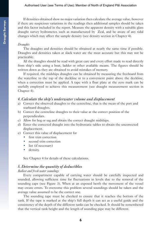
Every compartment capable of carrying water should be carefully inspected and sounded, allowing sufficient time for fluctuations in levels due to the removal of the sounding caps (see Figure 3). When at an exposed berth the movement of the vessel may create errors. To overcome this problem several soundings should be taken and the average value assumed to be the correct one.
The sounding tape must be checked to ensure that it reaches the bottom of the tank. If the tape is marked at the ship’s full depth it can act as a useful guide and the consistency of the depth of the different tanks can be checked. It should be remembered that the vertical tank height and the length of sounding pipe may be different.
Authorised User (see Terms of Use): Member of North of England P&I Association
7
Ch
apte
r 2
– P
ract
ical
Pro
ced
ure
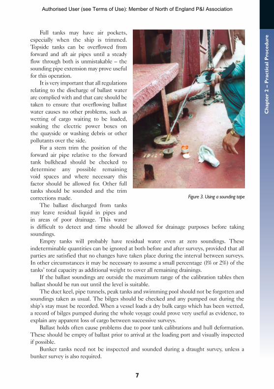
Full tanks may have air pockets, especially when the ship is trimmed. Topside tanks can be overflowed from forward and aft air pipes until a steady flow through both is unmistakable – the sounding pipe extension may prove useful for this operation.
It is very important that all regulations relating to the discharge of ballast water are complied with and that care should be taken to ensure that overflowing ballast water causes no other problems, such as wetting of cargo waiting to be loaded, soaking the electric power boxes on the quayside or washing debris or other pollutants over the side.
For a stern trim the position of the forward air pipe relative to the forward tank bulkhead should be checked to determine any possible remaining void spaces and where necessary this factor should be allowed for. Other full tanks should be sounded and the trim corrections made.
The ballast discharged from tanks may leave residual liquid in pipes and in areas of poor drainage. This water is difficult to detect and time should be allowed for drainage purposes before taking soundings.
Empty tanks will probably have residual water even at zero soundings. These indeterminable quantities can be ignored at both before and after surveys, provided that all parties are satisfied that no changes have taken place during the interval between surveys. In other circumstances it may be necessary to assume a small percentage (l% or 2%) of the tanks’ total capacity as additional weight to cover all remaining drainings.
If the ballast soundings are outside the maximum range of the calibration tables then ballast should be run out until the level is suitable.
The duct keel, pipe tunnels, peak tanks and swimming pool should not be forgotten and soundings taken as usual. The bilges should be checked and any pumped out during the ship’s stay must be recorded. When a vessel loads a dry bulk cargo which has been wetted, a record of bilges pumped during the whole voyage could prove very useful as evidence, to explain any apparent loss of cargo between successive surveys.
Ballast holds often cause problems due to poor tank calibrations and hull deformation. These should be empty of ballast prior to arrival at the loading port and visually inspected if possible.
Bunker tanks need not be inspected and sounded during a draught survey, unless a bunker survey is also required.
Figure 3. Using a sounding tape
Authorised User (see Terms of Use): Member of North of England P&I Association
8
Dra
ught
Sur
veys
See soundings and ullages section in Chapter 5.
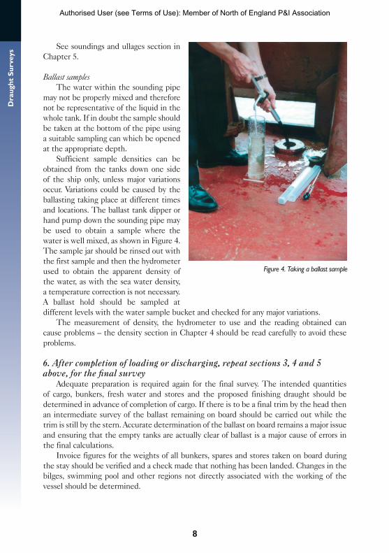
Ballast samples The water within the sounding pipe
may not be properly mixed and therefore not be representative of the liquid in the whole tank. If in doubt the sample should be taken at the bottom of the pipe using a suitable sampling can which be opened at the appropriate depth.
Sufficient sample densities can be obtained from the tanks down one side of the ship only, unless major variations occur. Variations could be caused by the ballasting taking place at different times and locations. The ballast tank dipper or hand pump down the sounding pipe may be used to obtain a sample where the water is well mixed, as shown in Figure 4. The sample jar should be rinsed out with the first sample and then the hydrometer used to obtain the apparent density of the water, as with the sea water density, a temperature correction is not necessary. A ballast hold should be sampled at different levels with the water sample bucket and checked for any major variations.
The measurement of density, the hydrometer to use and the reading obtained can cause problems – the density section in Chapter 4 should be read carefully to avoid these problems.
6. After completion of loading or discharging, repeat sections 3, 4 and 5 above, for the final survey
Adequate preparation is required again for the final survey. The intended quantities of cargo, bunkers, fresh water and stores and the proposed finishing draught should be determined in advance of completion of cargo. If there is to be a final trim by the head then an intermediate survey of the ballast remaining on board should be carried out while the trim is still by the stern. Accurate determination of the ballast on board remains a major issue and ensuring that the empty tanks are actually clear of ballast is a major cause of errors in the final calculations.
Invoice figures for the weights of all bunkers, spares and stores taken on board during the stay should be verified and a check made that nothing has been landed. Changes in the bilges, swimming pool and other regions not directly associated with the working of the vessel should be determined.
Figure 4. Taking a ballast sample
Authorised User (see Terms of Use): Member of North of England P&I Association
9
Ch
apte
r 2
– P
ract
ical
Pro
ced
ure
ACCURACY AND CONSISTENCYAll calculations contained in this guide should be carefully executed and agreed between
parties. The same survey methods should be used at the loading and the discharging ports to achieve consistency of results.
The calculations should deal only with the acquired facts and not introduce any unsubstantiated constants. The constant often referred to with draught surveys is dealt with in the lightship constant section in Chapter 3 and its significance should be understood.
All circumstances that may influence the accuracy of the surveys should be recorded on the survey report – see checklist in Appendix V.
Shortage claims on bulk cargoes are a major concern to the shipowner and their P&l clubs. They result in claims involving significant sums of money. Well maintained records when used as evidence, including accurate and comprehensively documented draught surveys from both the load and discharge ports, may enable these claims to be successfully defended.
Authorised User (see Terms of Use): Member of North of England P&I Association
10
Dra
ught
Sur
veys Chapter 3
INFORMATION REQUIRED
It is the master’s responsibility to ensure that the draught marks are clearly visible at a minimum of six positions on the hull, that is at the forward end, the aft end and midships, on both sides.
It is also the responsibility of the ship’s master to provide the surveyor with up- to-date and accurate information which has been certified by the ship’s flag state. This information should contain details of the ship and its present condition.
For details of what should be included refer to the information checklist in Appendix IV. The presentation and precision of the information will vary widely from ship to ship and the language may not be that of the surveyor.
Take great care when using the data. Read the stability information book introduction pages to determine the contents of each of the tables, and how they should be applied. Not all the information will be required for every draught survey.
The United Nations recommends that every ship carrying bulk cargoes should be provided with a data manual for draught surveys, which should be certified by the ship’s flag-state administration or its classification society.
UN recommendations for data manual for draught surveys
The language of the manual should be English or have English translations. The metric system of units should be used throughout.
Longitudinal measurements should be based upon midships.Sign convention: measurements forward are negative (–), measurements aft are
positive (+).Vertical measurements are to be taken from the bottom of the keel plate.It is recommended that vessels in excess of 200 m length overall (LOA) should be
marked at five points on each side: forward, midships and aft as usual and also at the mid points between these positions. This allows a more accurate assessment of any hogging or sagging effects.
The positions of the draught marks relative to the appropriate perpendicular should be included in the data manual.
Unfortunately such as data manual is often not available.
HYDROSTATIC PARTICULARSInformation is calibrated against draught, usually for the even-keel condition. The displacement is the weight of the ship, derived from volume of water
displaced by the ship × apparent density.In the metric system, the displacement is often given in tonnes of salt water at an
apparent density (weight in air) of 1.025 t/m3.It is important to establish the exact weight-to-volume relationship.
Authorised User (see Terms of Use): Member of North of England P&I Association
11
Ch
apte
r 3
– In
form
atio
n R
equ
ired
Draught and freeboardForward draught
The forward draught is the distance from the bottom of the keel to the waterline on the forward perpendicular when the ship is upright.
Aft draught The aft draught is the distance from the bottom of the keel to the waterline on the aft
perpendicular when the ship is upright.
Freeboard Freeboard is the distance from the waterline to the deckline, normally measured midships.
Depth of ship The depth of the ship is the distance from the bottom of the keel to the deckline. That is
Depth = draught + freeboard
Arithmetical mean draughtThe arithmetical mean of the forward draught and the aft draught will equal the draught
midships if there is no hog or sag. This is called the arithmetical mean draught (AMD).
True mean draught A ship trims about the longitudinal centre of flotation (LCF). When a ship trims due to
shifting a weight, that is no change of displacement, the only draught which does not change is the draught at the longitudinal centre of flotation. It is this draught which will give the appropriate displacement on the hydrostatic tables, and it is called the true mean draught (TMD). The position of the LCF is therefore critical to a draught survey.
Layer correctionThe difference between the true mean draught and the arithmetical mean draught is
known as the layer correction.
Trim factors Some stability information books tabulate trim factors, forward and aft, but no position
for the longitudinal centre of flotation (LCF) forward of the aft perpendicular (AP).The LCF can be found from the trim factors by the following formula
LCF from AP = length between perpendiculars × aft trim factor forward trim factor + aft trim factor
Trimmed hydrostatics Some ships are supplied with ‘trimmed hydrostatics’. These normally consist of several
sets of hydrostatic data each one calculated for a particular trim. They may be in 0.2 m steps covering the range of trims over which the vessel is expected to operate. Each set of hydrostatic data consists of displacements tabulated against draught for a particular density. The densities may be in increments of 0.005 from 1.000 to 1.025 and the draughts in 0.05 m
Authorised User (see Terms of Use): Member of North of England P&I Association
12
Dra
ught
Sur
veys
steps. Such tables avoid the need for both the first and second trim corrections and also the density correction described in Chapter 4.
Trimmed hydrostatic tables need to be interpolated for draught, density and trim to find the correct displacement. This interpolation is fairly difficult and needs careful thought to achieve an accurate result.
Check the use of trimmed hydrostatics in the introduction to the stability information book.
DEADWEIGHT OR DISPLACEMENT SCALEThe displacement, deadweight, tonnes per centimetre immersion (TPC) and moment to
change trim per centimetre (MCTC) for salt water are shown against the true mean draught (TMD) in the deadweight or displacement scale. It may also show the same for fresh water.
If only salt water values are given then the scale should be entered with the TMD in actual observed density. Calculations should be carried out with these figures as the density correction will take care of the adjustments at a later stage.
The scale will also show summer load draught and the lightship draught. It will relate the final TMD to the final displacement. Study it carefully to make certain of the weight-to -volume relationship.
PLANSCapacity plan
The capacity plan shows all the cargo compartments, ballast spaces and bunker tanks on the ship.
Capacity tables list every space in the ship which may be used for cargo, ballast, stores, fuel, lubricating oil and fresh water.
The position of each space is indicated by the number of the ship’s frames at each extremity of the space.
The volume of each space, in cubic metres, is listed for
• grain space – the gross volume measure to the ship’s side plating• bale space – the nett volume measured to the inside of the frames or spare ceiling
(cargo battens).
Spaces for liquid only are tabulated in either cubic metres or the number of tonnes of the liquid which the tank normally holds, specifying the density used to calculate those tonnes. If the tables give cubic metres then these must be multiplied by the observed density to find tonnes. If the tables give tonnes then they must be divided by the density of the table and multiplied by the observed density.
General arrangement planThe general arrangement plan shows the layout of the ship and indicates all the spaces
within it. It gives the position of all the spaces, their use and capacity.
Other plansMore detailed plans of ballast tanks and bunker tanks may be necessary.
Authorised User (see Terms of Use): Member of North of England P&I Association
13
Ch
apte
r 3
– In
form
atio
n R
equ
ired
If the vessel is trimmed it may be important to know the horizontal surface area of liquid in the tank and the relative position of the sounding pipe to assess the quantity of liquid in the tank accurately.
SOUNDING TABLESSounding tables are separate tables, often found in the care of the chief officer and/or
the chief engineer.The tables may be calibrated with either soundings or ullages.The calibrations may use cubic metres (i.e. tonnes of fresh water) or the average density
of the liquid which is normally carried in the tank and give tonnes of that liquid.For accurate assessment of the quantity of liquid in any tank, the actual density of the
liquid should be determined and the quantity re-calculated.
CORRECTION TABLES AND DIAGRAMSSounding correction tables
The sounding tables will have been calculated for the ship on an even keel.Correction tables should accompany any sounding table of a tank for which the sounding
pipe is not at the longitudinal centre of the tank.The table should give the correction for any sounding and for each metre of trim of the
ship over the normal operating range of trims and require interpolation for the actual trim. In the absence of such tables, calculations will have to be made from the original plans.
Trim correctionThe stability information book may include a table to apply the corrections for trim.
Investigate carefully whether this includes both the first and second trim corrections (see Chapter 4).
Position of marksThe stability information book may provide a correction to apply to the appropriate
draught readings to correct the reading to the value it would have had at the correct position (see Chapter 4).
Hull deflectionThe stability information book may provide a special means of calculating the vessel’s hull
distortion correction when calculating an accurate underwater volume (see Chapter 4).
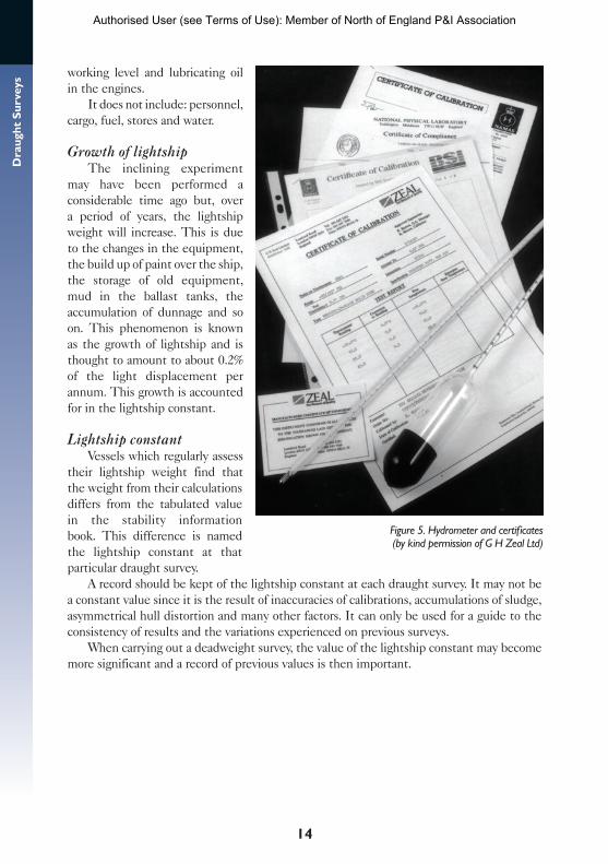
Hydrometer certificateCertificates of calibration issued by BSI British Standards, International Organization for
Standardization (ISO) or manufacturers such as Zeal provide the appropriate correction to apply to the hydrometer (see Figure 5).
LIGHTSHIPThe lightship weight is that which has been determined during an inclining
experiment.It includes: the ship and its full equipment, engine room spares, water in the boilers to
Authorised User (see Terms of Use): Member of North of England P&I Association
14
Dra
ught
Sur
veys
working level and lubricating oil in the engines.
It does not include: personnel, cargo, fuel, stores and water.
Growth of lightshipThe inclining experiment
may have been performed a considerable time ago but, over a period of years, the lightship weight will increase. This is due to the changes in the equipment, the build up of paint over the ship, the storage of old equipment, mud in the ballast tanks, the accumulation of dunnage and so on. This phenomenon is known as the growth of lightship and is thought to amount to about 0.2% of the light displacement per annum. This growth is accounted for in the lightship constant.
Lightship constantVessels which regularly assess
their lightship weight find that the weight from their calculations differs from the tabulated value in the stability information book. This difference is named the lightship constant at that particular draught survey.
A record should be kept of the lightship constant at each draught survey. It may not be a constant value since it is the result of inaccuracies of calibrations, accumulations of sludge, asymmetrical hull distortion and many other factors. It can only be used for a guide to the consistency of results and the variations experienced on previous surveys.
When carrying out a deadweight survey, the value of the lightship constant may become more significant and a record of previous values is then important.
Figure 5. Hydrometer and certificates (by kind permission of G H Zeal Ltd)
Authorised User (see Terms of Use): Member of North of England P&I Association
15
Ch
apte
r 4
– A
sses
smen
t o
f U
nd
erw
ater
Vo
lum
eChapter 4
ASSESSMENT OF UNDERWATER VOLUME
The underwater volume of the ship, and ultimately its displacement, is normally found by carefully reading and analysing the draught marks and by carefully establishing the density of water in which the vessel is floating.
The corrected mean draught is entered in the hydrostatic tables in the stability information book to find the appropriate displacement equivalent to this draught and density. The value must then be corrected to determine the precise weight of the ship in its present circumstances.
GENERAL DRAUGHT MEASUREMENTThe draught survey is based upon the accurate reading of the draught marks, therefore
no effort should be spared to achieve accuracy. Draughts should be measured in metres to two decimal places, that is to the nearest centimetre.
Before cargo operations commence, the water density and all six draught marks should be read, recorded and comments made on the prevailing conditions. During the time that the readings are being made, no transfer or discharge of liquid of any sort, or movement of any weight within the ship, should be allowed.
The draughts and density should be taken again on completion of the loading or discharging operation.
Measuring draughts in a swellIn turbulent conditions there may be waves, swell, pitching and rolling to take into
account. In these conditions, the wave pattern should be studied to establish the wave cycle. During a series of average waves the mean of the highest and lowest draught readings should be recorded.
A total of 12 mean readings should be obtained. The highest and lowest means should be rejected and then the average of the remaining ten will give the most accurate reading possible under the circumstances.
The forward, aft and midships draught measurements should all be found in a similar fashion.
Worked example: measuring draught in a swell
The following are mean draught readings (in metres) over an observed cycle of waves: 11.25, 9.80, 11.40, 9.70, 11.35, 9.75, 11.30, 9.60, 11.00, 9.90, 11.25, 9.70.Calculate the appropriate draught.
AnswerReject 11.40 and 9.60 m. Add remainder = 105.Estimated draught reading = 105 / 10 = 10.50 m.
Authorised User (see Terms of Use): Member of North of England P&I Association
16
Dra
ught
Sur
veys
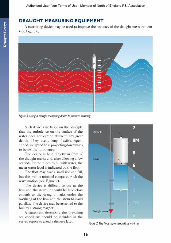
DRAUGHT MEASURING EQUIPMENTA measuring device may be used to improve the accuracy of the draught measurement
(see Figure 6).
Figure 6. Using a draught measuring device to improve accuracy
Such devices are based on the principle that the turbulence on the surface of the water does not extend down to any great depth. They use a long, flexible, open-ended, weighted hose projecting downwards to below the turbulence.
The device is held directly in front of the draught marks and, after allowing a few seconds for the tubes to fill with water, the mean water level is indicated by the float.
The float may have a small rise and fall, but this will be minimal compared with the wave motion (see Figure 7).
The device is difficult to use at the bow and the stern. It should be held close enough to the draught marks under the overhang of the bow and the stern to avoid parallax. The device may be attached to the hull by a strong magnet.
A statement describing the prevailing sea conditions should be included in the survey report to avoid a dispute later.
8
7M
4
2
88
7M
44
2
8
2
8M
Air hole
Float
Weight
6
Figure 7. The float movement will be minimal
Authorised User (see Terms of Use): Member of North of England P&I Association
17
Ch
apte
r 4
– A
sses
smen
t o
f U
nd
erw
ater
Vo
lum
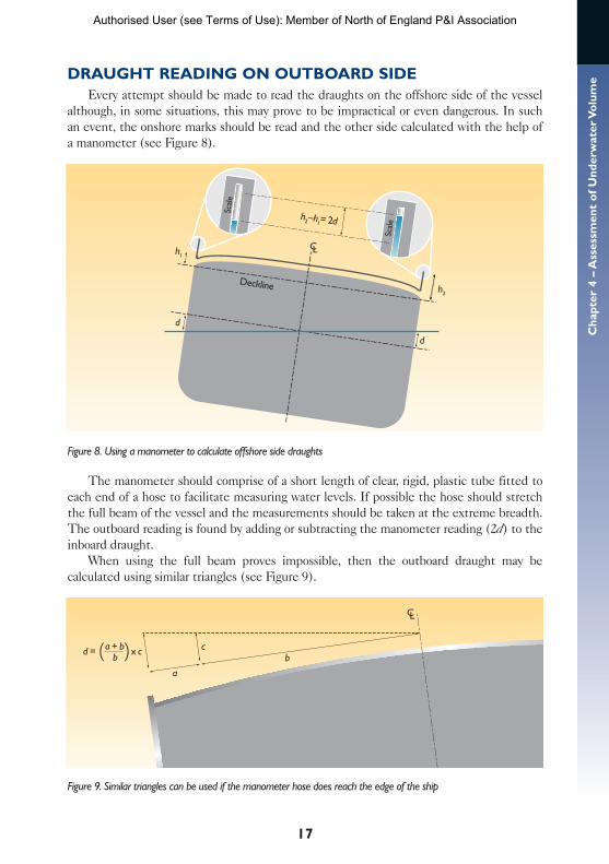
eDRAUGHT READING ON OUTBOARD SIDEEvery attempt should be made to read the draughts on the offshore side of the vessel
although, in some situations, this may prove to be impractical or even dangerous. In such an event, the onshore marks should be read and the other side calculated with the help of a manometer (see Figure 8).
Figure 8. Using a manometer to calculate offshore side draughts
The manometer should comprise of a short length of clear, rigid, plastic tube fitted to each end of a hose to facilitate measuring water levels. If possible the hose should stretch the full beam of the vessel and the measurements should be taken at the extreme breadth. The outboard reading is found by adding or subtracting the manometer reading (2d) to the inboard draught.
When using the full beam proves impossible, then the outboard draught may be calculated using similar triangles (see Figure 9).
Figure 9. Similar triangles can be used if the manometer hose does reach the edge of the ship
Deckline
h2–h
1= 2d
d
d
h1
h2
Scal
e
Scal
e
( ) c
a
a + bb
x cd =b
Authorised User (see Terms of Use): Member of North of England P&I Association
18
Dra
ught
Sur
veys
The levels must be measured from the same base line, and taken at equal distances from the centreline on both sides of the vessel.
All air must be excluded from the hose and the water levels in both tubes kept at a height which is higher than the deck at the centreline.
The heights of water levels, on both sides of the ship, are measured above the deckline (h) or some other fixed level. The difference between the two heights is then halved and the result (d) is added to, or subtracted from, the one draught reading to obtain the mean draught at the centreline.
Worked example: measuring draught with a manometer
The port draught midships = 8.00 m.The starboard side is to be found by manometer, where the readings are taken at 8.50 m on either side of the centre line.The vessel’s full beam = 20.85 m.Calculate the midships mean draught (i.e. centreline draught) if there is a difference of 0.25 m between the two readings of the manometer and the starboard reading is the higher.
AnswerEffective manometer beam = 8.50 × 2 = 17.00 m.By similar triangles 0.25 / 17 = d / 20.85 d= 20.85 × 0.25 / 17 = 0.31 full beam difference.Half beam difference = 0.31 / 2 = 0.15 m.Centreline draught = 0.15 + 8.00 = 8.15 m.
It may be more practical in some situations to measure the midships freeboard and from this calculate the midships draught.
DRAUGHT GAUGESDraught gauges may be very helpful as a check, but should never replace the reading of
draughts using the fixed draught marks on the ship’s hull.
SQUATWhen there is a strong current running and there is water depths of less than twice the
draught of the vessel, the draught readings may be misleading due to the effects of squat.The survey report should include reference to possible squat effects, even if a suitable
correction to the draught readings cannot be determined. See checklist of factors which may influence survey accuracy in Appendix V.
CORRECTION OF DRAUGHTS TO PERPENDICULARS AND MIDSHIPS
Firstly, correct observed draughts, forward, aft and midships, for the effect of any list or heel by calculating the mean of port and starboard in each case.
There may also be a list correction (in tonnes) to apply to the displacement (see page 22).
Authorised User (see Terms of Use): Member of North of England P&I Association
19
Ch
apte
r 4
– A
sses
smen
t o
f U
nd
erw
ater
Vo
lum
e
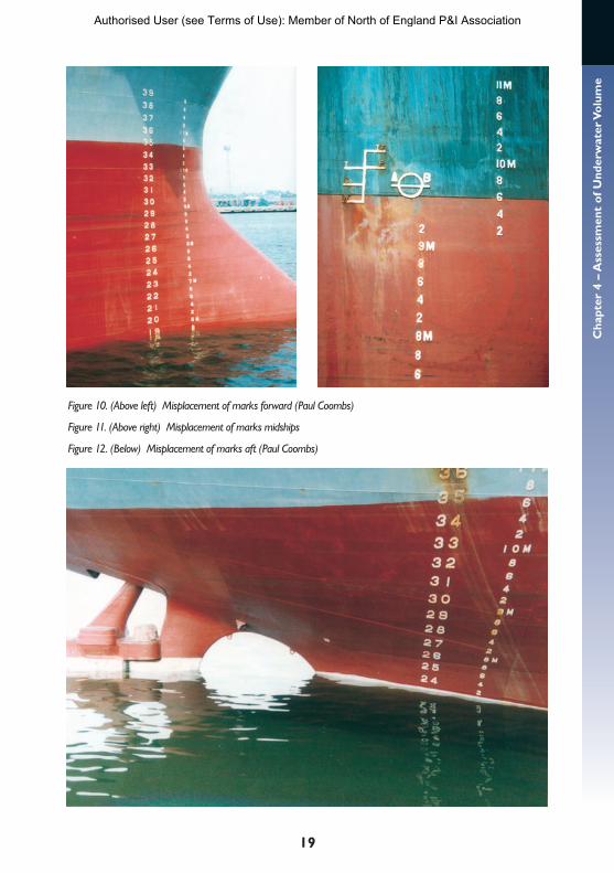
Figure 10. (Above left) Misplacement of marks forward (Paul Coombs)
Figure 11. (Above right) Misplacement of marks midships
Figure 12. (Below) Misplacement of marks aft (Paul Coombs)
Authorised User (see Terms of Use): Member of North of England P&I Association
20
Dra
ught
Sur
veys
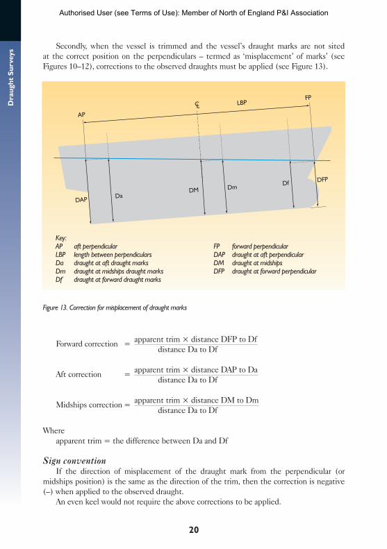
Secondly, when the vessel is trimmed and the vessel’s draught marks are not sited at the correct position on the perpendiculars – termed as ‘misplacement’ of marks’ (see Figures 10–12), corrections to the observed draughts must be applied (see Figure 13).
Figure 13. Correction for misplacement of draught marks
Forward correction = apparent trim × distance DFP to Df distance Da to Df
Aft correction = apparent trim × distance DAP to Da distance Da to Df
Midships correction = apparent trim × distance DM to Dm distance Da to Df
Whereapparent trim = the difference between Da and Df
Sign conventionIf the direction of misplacement of the draught mark from the perpendicular (or
midships position) is the same as the direction of the trim, then the correction is negative (–) when applied to the observed draught.
An even keel would not require the above corrections to be applied.
AP
LBPFP
DFPDf
DmDMDa
DAP
Key:AP aft perpendicular FP forward perpendicularLBP length between perpendiculars DAP draught at aft perpendicularDa draught at aft draught marks DM draught at midshipsDm draught at midships draught marks DFP draught at forward perpendicularDf draught at forward draught marks
Authorised User (see Terms of Use): Member of North of England P&I Association
21
Ch
apte
r 4
– A
sses
smen
t o
f U
nd
erw
ater
Vo
lum
eWorked example: correction of draught mark observations
With reference to the following particulars, calculate the correct forward and aft draughts, if the observed draughts are: forward 6.35 m, aft 7.88 m.
Position of draught marks: forward 1.82 m aft of FP, aft 6.00 m forward of AP. LBP = 170 m.
AnswerApparent trim = 7.88 – 6.35 = 1.53 mLength between marks = 170 – (6.0 + 1.82) = 162.18 mCorrection forward = 1.53 × 1.82 / 162.18 = –0.02 mDraught forward = 6.35 – 0.02 = 6.33 mCorrection aft = 1.53 × 6.00 / 162.18 = +0.06 mDraught aft = 7.88 + 0.06 = 7.94 m
Misplacement corrections with hull deflectionThe corrections to the perpendiculars and midships assume that the keel of the vessel is
straight. When the vessel is hogged or sagged (see page 22), these corrections may no longer be correct. The tabulated corrections in the stability information book, or the formulae on the previous page, must be corrected to the particular circumstances.
The easiest method is to use the trim between the midships mark and the particular end draught then calculate using this half length trim, the half-length and the distance of the misplacement.
Repeat the procedure at the other end draught mark with the similarly modified trim, the half length and the distance of misplacement.
Worked example: correction of draught mark observations with hull deflection
Observed draughts: forward 6.00 m, midships 6.40 m, aft 7.40 m.
Distance of forward mark from FP = 2.00 m aft, distance of aft mark from AP = 5.00 m forward. LBP = l00 m.
AnswerTotal trim = 1.40 m, AMD = 6.70 m, therefore the vessel is hogged.Trim forward midships = 0.40 mForward correction = 2 × 0.40 / (50 – 2) = –0.02 mForward draught = 5.98 mTrim aft to midships = 1.00 m Aft correction 5.00 × 1.00 / (50 – 5) = +0.11 m Aft draught = 7.51 m
Authorised User (see Terms of Use): Member of North of England P&I Association
22
Dra
ught
Sur
veys
CORRECTION FOR LISTWhen a vessel lists, it often rises in the water. This means that the mean of the side
draughts is a centreline draught, which is less than the actual draught that would have been observed had the vessel been upright. This may be ignored for small angles of list. However, if the draught survey is to be carried out on a vessel which has suffered a cargo shift or is lying at a large angle of list, then it should be calculated.
The correction, in tonnes, to be applied to the displacement is by the formula
Correction for list (tonnes) = 6 (TPC2 – TPC1) × (d2 – d1)
Whered2 and d1 = midships draughts on each sideTPC1 = the TPC equivalent to the draught d1TPC2 = the TPC equivalent to the draught d2.
Sign conventionAlways positive (+).
Worked example: displacement correction for list
Vessel is listed 5º. The draughts midships are: port 6.00 m (equivalent TPC = 32), starboard 8.00 m (equivalent TPC = 34).
Answer
Correction = 6 (34 – 32) (8.00 – 6.00) = 24 t positive (+)
(It will normally be a small correction.)
CORRECTION FOR HULL DEFLECTION (HOG AND SAG)When the observed draughts have been corrected for list and displacement of marks,
an arithmetical mean of the forward and aft draughts must be calculated, that is the arithmetical mean draught (AMD).
Compare the AMD with the corrected midships draught to establish whether the hull is distorted. The AMD should equal the draught midships if the ship is neither hogged or sagged.
If the actual draught is less than AMD then the vessel is hogged. If the actual draught is greater than AMD then the vessel is sagged (see Figure 14).
Every effort should be made, taking into account the information available, to determine the appropriate correction for hull deflection. The ultimate accuracy of the survey results are normally dependant on this correction.
It is difficult to establish the ship’s distorted shape precisely but the following factors should be taken into account
Authorised User (see Terms of Use): Member of North of England P&I Association

23
Ch
apte
r 4
– A
sses
smen
t o
f U
nd
erw
ater
Vo
lum
e
• residual deformation • cargo distribution• bunkers / ballast distribution• daily variation.
Larger vessels can be liable to daily variations in the amount of hull deflection. By day, the sun heats the upper parts of the vessel, resulting in a hogged condition. The same vessel may suffer sagging when the upper portion loses its heat at night.
The assessment of the vessel’s shape will establish the appropriate draught to enter in the hydrostatic data in the stability information book. This will determine the displacement for that particular instant.
Methods of calculating hull-deflection correctionThere are several methods of calculating the correction for hog or sag. Agreement on
the use of one of these alternatives must be made before the proposed voyage begins and adhered to until the voyage ends. These methods only take into account hull deformation or deflection.
Method 1Some ship’s stability information books have a table of corrections to apply to the
extracted displacement. When the table or graph is used, then this fact should be stated on the report so that it can be used throughout.
Method 2 (the most common and simplest method) Assume that the deformed shape of the vessel follows a regular mathematical curve.The correction is dependant on the block coefficient.
Actual freeboard
Actual draught AMD
HOG
Actual freeboard
Actual draughtAMD
SAG
Figure 14. Identifying hog or sag using the arithmetical mean draught (AMD)
Authorised User (see Terms of Use): Member of North of England P&I Association
24
Dra
ught
Sur
veys
(i) For finer-lined vessels
Mean adjusted draught = (6 × DM) + DFP + DAP 8
This is often referred to as ‘the mean of mean of means’.
(ii) For fuller-form vessels, and box-shaped vessels
Mean adjusted draught = (4 × DM) + DFP + DAP 6
Wheremean adjusted draught = draught midships corrected for hog and sag DM = draught midships DFP = draught at forward perpendicular DAP = draught at aft perpendicular.
Worked example: method 2 for calculating mean draught with hull deflection
The vessel has a sleek form for a fast passage, but is suffering from hull deflection. The draughts at the perpendiculars are: forward 5.64 m, aft 6.42 m. The draught midships is 6.11 m.What is the mean adjusted draught, taking into account the distortion of the hull.
Answer
Mean adjusted draught = (6 × 6.11) + 5.64 + 6.42 = 6.09 m 8
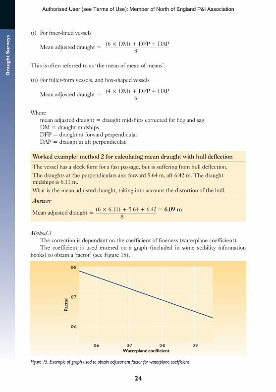
Method 3
The correction is dependant on the coefficient of fineness (waterplane coefficient).The coefficient is used entered on a graph (included in some stability information
books) to obtain a ‘factor’ (see Figure 15).
Figure 15. Example of graph used to obtain adjustment factor for waterplane coefficient
0.8
0.7
0.6
0.6 0.7Waterplane coefficient
Fact
or
0.8 0.9
Authorised User (see Terms of Use): Member of North of England P&I Association
25
Ch
apte
r 4
– A
sses
smen
t o
f U
nd
erw
ater
Vo
lum
e
ThenMean adjusted draught = AMD + factor (DM – AMD)
Worked example: method 3 for calculating mean draught with hull deflection
A vessel is floating at the following draughts: forward 5.80 m, aft 6.20 m, midships 6.18 m.These draughts have been corrected to the perpendiculars and midships marks.Calculate the mean adjusted draught taking into account the distortion of the hull using the waterplane coefficient table. The waterplane coefficient tabulated in the stability information book = 0.60.
AnswerExtracted factor 0.76AMD = (5.80 + 6.20) / 2 = 6.00 mMean adjusted draught = 6.00 + 0.76 (6.18 – 6.00) = 6.14 m
Method 3 alternative 1The extracted factor can be used directly to determine a correction in tonnes to apply
to the final displacement.
Correction (tonnes) = factor × TPC × 100 × hog or sag
Wherehog or sag = (difference between DM and AMD)
Method 3 alternative 2The graph or table itself may be adapted to give a correction table directly in tonnes (i.e.
factor × TPC × 100) for each metre of hog or sag. This would give a correction to apply to the final displacement by entering the table with the AMD and the hog or sag in metres.
Other methods Alternative methods require additional draught/freeboard measurements at points
other than perpendiculars and midships, along the vessel’s length. This is very difficult to establish (see data manual for draught surveys in Chapter 3).
CORRECTIONS FOR TRIMThere may be a total trim correction table included in the stability information book.
This will normally combine the following first and second corrections. Find out what it includes, and examine the ship’s stability data carefully before conducting a survey.
First trim correction (correction for layer)The displacement scale is normally calculated on the assumption that the vessel is lying
on an even keel. The first trim correction is to correct the draught midships to the true mean draught, at the centre of flotation.
This correction is also known as the correction for layer or layer correction (see Figure 16).
Authorised User (see Terms of Use): Member of North of England P&I Association
26
Dra
ught
Sur
veys
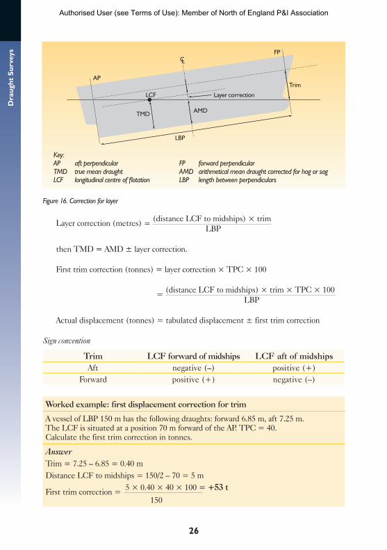
Figure 16. Correction for layer
Layer correction (metres) = (distance LCF to midships) × trim LBP
then TMD = AMD ± layer correction.
First trim correction (tonnes) = layer correction × TPC × 100
= (distance LCF to midships) × trim × TPC × 100 LBP
Actual displacement (tonnes) = tabulated displacement ± first trim correction
Sign convention
Trim LCF forward of midships LCF aft of midshipsAft negative (–) positive (+)
Forward positive (+) negative (–)
Worked example: first displacement correction for trim
A vessel of LBP 150 m has the following draughts: forward 6.85 m, aft 7.25 m. The LCF is situated at a position 70 m forward of the AP. TPC = 40. Calculate the first trim correction in tonnes.
AnswerTrim = 7.25 – 6.85 = 0.40 mDistance LCF to midships = 150/2 – 70 = 5 m
First trim correction = 5 × 0.40 × 40 × 100 = +53 t
150
AP
LBP
LCF Layer correction
Trim
TMD AMD
FP
Key:AP aft perpendicular FP forward perpendicular TMD true mean draught AMD arithmetical mean draught corrected for hog or sag LCF longitudinal centre of flotation LBP length between perpendiculars
Authorised User (see Terms of Use): Member of North of England P&I Association
27
Ch
apte
r 4
– A
sses
smen
t o
f U
nd
erw
ater
Vo
lum
eSecond trim correctionThe second trim correction is for the shift of the centre of flotation (LCF) which occurs
as the vessel changes its trim. The position of the LCF, as specified in the hydrostatic particulars, is normally for the even-keel condition.
The draught at the final position of LCF is required.
Second trim correction (metres) = trim × (MCTC2 –MCTC1) 2 × TPC × LBP
WhereMCTC2 = MCTC for the draught at the AP MCTC1 = MCTC for the draught at the FP or vice versa when trimmed by the head.
However the second trim correction is normally calculated in tonnes as follows:
Second trim correction (tonnes) = 50 × trim2 × (MCTC2 –MCTC1) LBP
Where MCTC2 = MCTC for mean adjusted draught + 0.5 m MCTC1 = MCTC for mean adjusted draught – 0.5 m
Actual displacement (tonnes) = tabulated displacement +– second trim correction
Sign conventionAlways positive (+).
Worked example: second displacement correction for trim
A vessel is floating in salt water with an AMD of 6.10 m corrected for deflection and a trim of 1.40 m by the stern.Extracted values from hydrostatics: MCTC for 5.60 m = 310.0, MCTC for 6.60 m = 322.90, LBP = 170 m.Calculate the second trim correction in tonnes for the vessel in this condition.
AnswerTrim = 1.40 m
Second trim correction = 50 × 1.402 × (322.90 – 310.0) = +7.4 t
170
DENSITYDetermine the water density at the time of taking the draughts using a glass hydrometer,
which is designed for draught surveys and marked
1. medium surface tension2. apparent density in kg / l scale range between 0.990 to 1.040 (1.000 kg/l = 1.000 t/m3)3. instrumental standard 15° C.
Authorised User (see Terms of Use): Member of North of England P&I Association
28
Dra
ught
Sur
veys
The instrument should be provided with a certificate of calibration with a maximum error not exceeding ‘x’ kg/l tested against a national standard (see Figure 5).
If the hydrometer used is graduated with a different scale then it is not the standard type so additional corrections may be required – see details for alternative hydrometers in Appendix VI.
Correction for density
Actual displacement (tonnes) = tabulated displacement × density 1 density 2
Where density 1 = average density of water sampleddensity 2 = density specified in the hydrostatic information.
Notes1. Do apply the hydrometer index error, if any. It is quoted on the certificate.2. Do not apply any correction for temperature.3. Do not adjust the draught for the density, but do correct the displacement instead.4. Do enter in the hydrostatic tables the actual TMD, irrespective of density, and then
convert the extracted value to the correct density at the final calculation. It is wrong to convert the TMD to a salt water TMD and then enter it in the hydrostatics.
5. Do extract MCTC, LCF and so on for the actual TMD and use these extracted values to calculate the first and second trim corrections.
6. The stability information book should quote some form of relationship between weight and volume:
1 cubic metre of fresh water 1 tonne1 cubic metre of salt water 1.025 tonnes
or similar figures.
The following example gives apparent density in the same units used by a standard draught survey hydrometer.
Worked example: displacement correction for density
The extracted hydrographic displacement equivalent to the observed draught of 5.30 m = 15,250 t for salt water where 1 m3 of salt water = 1.025 t.Find: true displacement if the average observed apparent density = 1.015 t/m3
AnswerActual displacement = 15,250 × 1.015 / 1.025 = 15,101 t
Authorised User (see Terms of Use): Member of North of England P&I Association
29
Ch
apte
r 4
– A
sses
smen
t o
f U
nd
erw
ater
Vo
lum
eASSESSMENT SUMMARYThe corrections in this chapter may be applied to the observed draughts to convert
them to a draught that can be used to enter in the ship’s hydrostatic particulars to determine the correct displacement.
Some of the corrections may be calculated in tonnes or in metres. Experience and speed of calculation has shown that these corrections should be calculated in tonnes (instead of metres), and used to correct a value of displacement extracted from the hydrostatic particulars in the stability information book.
The observed draughts are corrected to the perpendiculars and midships, the hull deflection found and the hydrostatics entered with the corrected arithmetical mean draught (AMD). The displacement extracted is then adjusted with the first and second trim corrections and the correction for density, all in tonnes.
A corrections checklist is provided in Appendix VII.
Authorised User (see Terms of Use): Member of North of England P&I Association
30
Dra
ught
Sur
veys Chapter 5
DEDUCTIBLES
The deductibles are the components of the ship’s total weight, which must be deducted from the calculated displacement to determine the weight of cargo on board.
The total weight of the ship will be made up of
• light displacement (remember components may be missing e.g. anchors out)• cargo • ballast • fuel and fresh water• swimming pool water and other easily forgotten weights on board• stores and provisions • crew and effects.
Stores, provisions, crew and their effects are likely to be constant during a draught survey, and could be added on to the light displacement.
PreparationsExamine the relevant basic ship’s plans showing the layout of pipes and tanks, including
the location of their sounding pipes.Make a note of the tank dimensions, reference heights and obtain the authorised
calibration tables for these tanks.Remember that automatic gauge readings (if fitted), should be noted for comparison
against the manual readings.
SOUNDINGS AND ULLAGESThe liquid quantities of ballast, fuel and fresh water must be carefully measured as soon
as possible after the draughts have been read.A sounding is the measurement from the striker plate on the base of the tank below the
sounding pipe to the top of the liquid (see Figure 3).When taking a sounding, always check the tape is at the bottom of the tank, by checking
the full measurement from the striker plate to the top of the sounding pipe.An ullage is the measurement from the surface of the liquid to a fixed datum point,
usually the top of the sounding pipe.Measure and record soundings (or ullages) for every tank in the ship.Check the bilges for any liquid.Some tanks may have two sounding pipes, check both, particularly if the ship is
trimmed.The sounding tables should be part of the ship’s approved documentation, they are
produced when the vessel is built and therefore may have become less accurate with the passage of time.
Authorised User (see Terms of Use): Member of North of England P&I Association
31
Ch
apte
r 5
– D
edu
ctib
lesSAMPLING
By sounding a tank and using the sounding tables, the volume of liquid is found. With the apparent density of the liquid, its mass can be determined.
Mass = volume × apparent density
It is most important that each tank should be sampled for density as well as being sounded for volume (see Figure 4).
Apply the temperature correction to the density reading before using it to calculate the quantity of bunkers in a tank when doing a bunker tank survey. It is not normal to apply a temperature correction when determining ballast quantities.
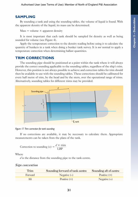
TRIM CORRECTIONSThe sounding pipe should be positioned at a point within the tank where it will always
provide the correct sounding applicable to the sounding tables, regardless of the ship’s trim. However, this position is not always possible to achieve and correction tables for trim should then be available to use with the sounding tables. These corrections should be calibrated for every half metre of trim, by the head and by the stern, over the operational range of trims. Alternatively, sounding tables for different trims may be provided.
Figure 17. Trim correction for tank sounding
If no corrections are available, it may be necessary to calculate them. Appropriate measurements can be taken from the plans of the tank.
Correction to sounding (x) = d × trim LBP
Whered is the distance from the sounding pipe to the tank centre.
Sign convention
Trim Sounding forward of tank centre Sounding aft of centreForward Negative (–) Positive (+)
Aft Positive (+) Negative (–)
Sounding pipe
x
d
tank
Authorised User (see Terms of Use): Member of North of England P&I Association
32
Dra
ught
Sur
veys
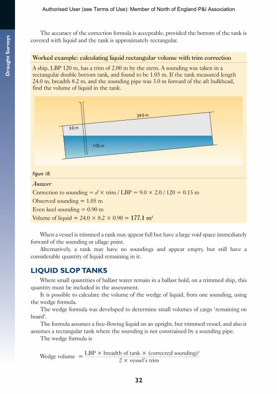
The accuracy of the correction formula is acceptable, provided the bottom of the tank is covered with liquid and the tank is approximately rectangular.
Worked example: calculating liquid rectangular volume with trim correction
A ship, LBP 120 m, has a trim of 2.00 m by the stern. A sounding was taken in a rectangular double bottom tank, and found to be 1.05 m. If the tank measured length 24.0 m, breadth 8.2 m, and the sounding pipe was 3.0 m forward of the aft bulkhead, find the volume of liquid in the tank.
24.0 m
3.0 m
1.05 m
Figure 18.
AnswerCorrection to sounding = d × trim / LBP = 9.0 × 2.0 / 120 = 0.15 mObserved sounding = 1.05 mEven keel sounding = 0.90 mVolume of liquid = 24.0 × 8.2 × 0.90 = 177.1 m3
When a vessel is trimmed a tank may appear full but have a large void space immediately forward of the sounding or ullage point.
Alternatively, a tank may have no soundings and appear empty, but still have a considerable quantity of liquid remaining in it.
LIQUID SLOP TANKSWhere small quantities of ballast water remain in a ballast hold, on a trimmed ship, this
quantity must be included in the assessment.It is possible to calculate the volume of the wedge of liquid, from one sounding, using
the wedge formula.The wedge formula was developed to determine small volumes of cargo ‘remaining on
board’.The formula assumes a free-flowing liquid on an upright, but trimmed vessel, and also it
assumes a rectangular tank where the sounding is not constrained by a sounding pipe.The wedge formula is
Wedge volume = LBP × breadth of tank × (corrected sounding)2
2 × vessel’s trim
Authorised User (see Terms of Use): Member of North of England P&I Association
33
Ch
apte
r 5
– D
edu
ctib
les
Figure 18.
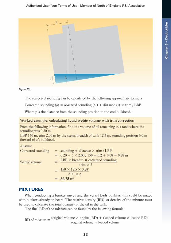
The corrected sounding can be calculated by the following approximate formula
Corrected sounding (p) = observed sounding (p1) + distance (y) × trim / LBP
Where y is the distance from the sounding position to the end bulkhead.
Worked example: calculating liquid wedge volume with trim correction
From the following information, find the volume of oil remaining in a tank where the sounding was 0.20 m.LBP 150 m, trim 2.00 m by the stern, breadth of tank 12.5 m, sounding position 6.0 m forward of aft bulkhead.
AnswerCorrected sounding = sounding + distance × trim / LBP = 0.20 + 6 × 2.00 / 150 = 0.2 + 0.08 = 0.28 m
Wedge volume = LBP × breadth × corrected sounding2
trim × 2 = 150 × 12.5 × 0.282
2.00 × 2 = 36.75 m3
MIXTURESWhen conducting a bunker survey and the vessel loads bunkers, this could be mixed
with bunkers already on board. The relative density (RD), or density, of the mixture must be used to calculate the total quantity of the oil in the tank.
The final RD of the mixture can be found by the following formula
RD of mixture = (original volume × original RD) + (loaded volume × loaded RD) original volume + loaded volume
y
pp1
Authorised User (see Terms of Use): Member of North of England P&I Association
34
Dra
ught
Sur
veys
RESIDUE IN COMPARTMENTSTanks for liquids, particularly ballast tanks, are subject to the build up of residues and
scale. The quantity of sediment is difficult to assess without entering the tank.The effect on the ballast calculations can be minimised by leaving a measurable quantity
of water in the tank instead of pumping it completely dry. The calculations then use a known amount of water which can be deducted from the displacement. The error due to the unknown weight of sediment is reduced to the difference between the density of water and the density of the sediment. The accumulation of sediment will reduce the deadweight capacity of the vessel and therefore should not be allowed to accrue indefinitely.
Inspect ballast tanks if in any doubt about the quantity of sediments. There are patent chemicals available to put the mud into suspension so that it may be disposed of with the water in an appropriate and safe manner when a suitable opportunity allows. However, these may not always be effective; when a hard crust has developed on the top of the mud, it can sometimes only be removed by hand.
ANCHORS AND CABLESThe anchors may be in the housed position, where they contribute to the lightship, or
they may have been used in the mooring of the ship. Then the anchors will be on the sea bed along with a given length of cable. The loss of weight due to their removal is weight taken from the light displacement – this amount should therefore be added to the quantity of cargo. There should be information available on board to enable the surveyor to establish or calculate the weight of the missing anchor and cable.
In the case of the chain cable, it can be calculated with reasonable accuracy by the following formula
Weight per shackle (27.43 m) (tonnes) = 0.0005805 x (link diameter in mm)2
The link diameter is the diameter of the steel rod which makes up each individual link. In the case of the anchor itself, this will vary from ship to ship, but the information should be available on board. The anchor weight should be rounded to the nearest half tonne.
ADDITIONAL FACTORSIt should be appreciated that the cargo may change its characteristics over a period of
time. The moisture content varies with the atmospheric conditions, and liquid drains into the bilges. The removal of bilge water between the two surveys should be noted. This is also important during a voyage when a wetted cargo may lose its moisture content and later cause a dispute over cargo quantities.
The changes in the condition of the vessel such as the accumulation of rain water, ice or snow, could be significant and should be accounted for in the calculations.
The swimming pool can hold considerable quantities of water, which could cause a discrepancy if the pool is emptied, or filled, during the period between the before and after draught surveys. In this case a correction must be applied to the results.
All spaces should be inspected to ensure they are the same at both the initial and final surveys, not forgetting spaces such as the duct keel, peaks, cofferdams and so on.
Remember: the accuracy of the survey depends on diligence!
Authorised User (see Terms of Use): Member of North of England P&I Association

35
Ap
pen
dix
I –
Glo
ssar
yAPPENDIX IGLOSSARY
Aft draught The distance from the bottom of the keel to the waterline on the aft perpen-dicular when the ship is upright.
Aft perpendicular (AP) A perpendicular drawn to the waterline at the point where the aft side of the rudder post meets the summer load line. Where no rudder post is fitted it is taken as the centre line of the rudder stock.
Apparent density The weight in air of a unit volume.Apparent trim The difference between the draughts observed at the forward and aft
draught marks.Arithmetical mean draught (AMD) The arithmetical mean of the forward draught and
the aft draught.Assigned summer freeboard The distance from the upper edge of the summer load line
to the upper edge of the deck line.Block coefficient (Cb) The ratio of the underwater volume of the vessel to the volume of
a rectangular block of the same overall dimensions.Breadth (beam) Maximum width of the ship.Centre of flotation (CF) The centroid of the waterplane area. It is the point about which
the ship trims, heels and lists.Deadweight The difference between the light displacement and the loaded displacement.
It is the carrying capacity of the ship and includes the weight of cargo, ballast, fuel, water, stores, crew and effects.
Density The mass per unit volume.Depth Distance from the top of the deck plating at the side of the ship to the bottom of
the keel.Displacement The mass of water displaced by the ship. It represents the total weight of
the ship and is calculated by: volume of displacement × density of water.Draught The distance from the bottom of the keel to the waterline. Sometimes spelled draft.Even keel When the forward and aft draughts are the same, the ship is said to be on an
even keel. The ship’s hydrostatic data is calculated for this condition.Forward draught The distance from the bottom of the keel to the waterline on the for-
ward perpendicular when the ship is upright.Forward perpendicular (FP) A perpendicular drawn to the waterline at the point where
the fore side of the stem meets the summer load line (or load waterline LWL).Freeboard The distance from the waterline to the upper surface of the freeboard deck at
the ship’s side.Fresh water allowance (FWA) The amount by which the summer load line may be sub-
merged in fresh water.Heel The ship is heeled when inclined by an external force .Hog The condition of a ship when it is deformed so that the forward and aft draughts are
deeper than the midships draught. It is referred to as a hull deflection.
Authorised User (see Terms of Use): Member of North of England P&I Association

36
Dra
ught
Sur
veys
Length between perpendiculars (LBP) Distance from the forward perpendicular to the aft perpendicular.
Length overall (L or LOA) Maximum length of the ship.Light displacement The displacement of the ship and superstructure with all fixed equip-
ment plus engine room spares and with water in the boilers to working level. Also referred to as lightship or lightweight.
List The ship is listed when inclined by weights within the ship.Longitudinal centre of flotation (LCF) The distance of the centre of flotation from
midships or the aft perpendicular.Mass The mass of an object is the quantity of matter it contains and is calculated by: vol-
ume × densityMidships The point midway between the forward and aft perpendiculars. The centre of
the load line circle should indicate this position.Midships draught The distance from the bottom of the keel to the waterline at a position
midway between the perpendiculars.Moment to change trim per centimetre (MCTC or MCT1cm) The moment of the
weight (i.e. weight × distance) required to change the trim of the ship by 0.01 m.Moulded breadth Width of the ship amidships, measured inside the shell plating.Moulded depth Distance from the keel to the deck the ship’s side, measured inside of the
shell plating.Relative density (RD) The ratio of the weight of a substance to the weight of an equal vol-
ume of fresh water. RD of fresh water: 1.000 at 4°C. RD of salt water: 1.025 at 4°C. The term specific gravity, previously used in place of RD, is no longer used with SI units.
Sag The condition of a ship when it is deformed so that the midships draught is deeper than the forward and aft draughts. It is referred to as a hull deflection.
Sounding The distance from the bottom of a tank to the top of the liquid within it.Summer load displacement The displacement of the ship when loaded to its summer
load line.Tonnes per centimetre immersion (TPC) The weight which must be loaded or dis-
charged to change the ship’s mean draught by 0.01 m.Trim The difference between the forward and aft draughts.True density The weight in a vacuum of a unit volume.True mean draught (TMD) The draught at the centre of flotation.True trim The difference between the draughts at the forward and aft perpendiculars.Ullage The distance above a liquid, within a tank, to the measuring point at the top of
the tank.Volume of displacement The volume of water displaced by a ship and is calculated by:
length × breadth × draught × block coefficient (Cb).Waterplane coefficient (Cw) The ratio of the area of the ship’s waterplane to a rectangle
of the same extreme dimensions. Also known as the coefficient of fineness.Weight The weight of an object is the force it exerts on anything which freely supports it.
Authorised User (see Terms of Use): Member of North of England P&I Association
37
Ap
pen
dix
II
– U
N E
CE
Dra
ugh
t S
urv
ey C
od
e Fo
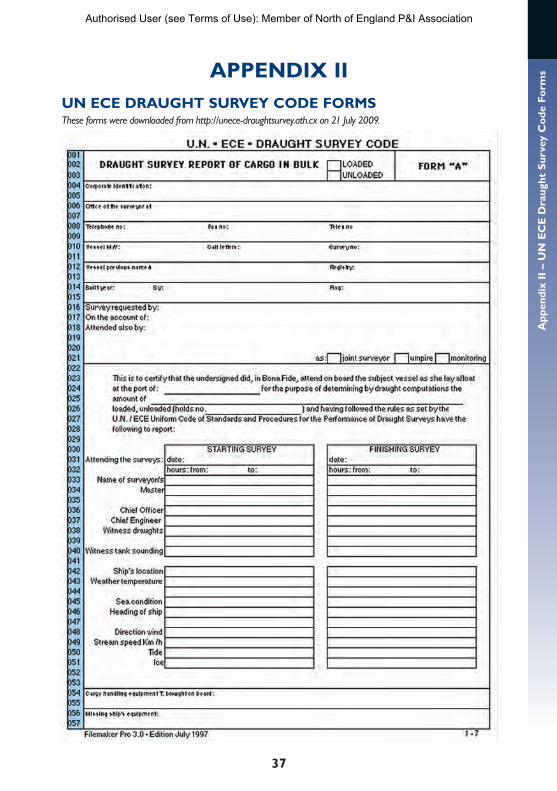
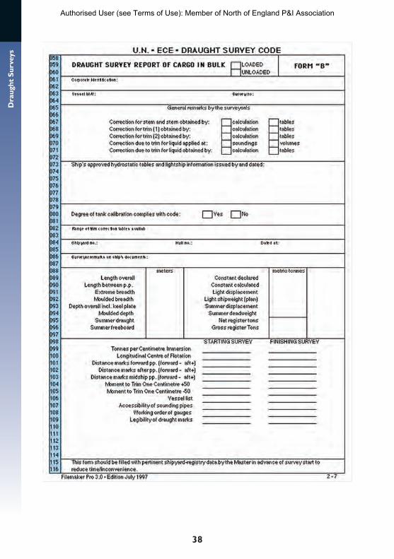
rmsAPPENDIX II
UN ECE DRAUGHT SURVEY CODE FORMSThese forms were downloaded from http://unece-draughtsurvey.ath.cx on 21 July 2009.
Authorised User (see Terms of Use): Member of North of England P&I Association
38
Dra
ught
Sur
veys
Authorised User (see Terms of Use): Member of North of England P&I Association
39
Ap
pen
dix
II
– U
N E
CE
Dra
ugh
t S
urv
ey C
od
e Fo
rms
Authorised User (see Terms of Use): Member of North of England P&I Association
40
Dra
ught
Sur
veys
Authorised User (see Terms of Use): Member of North of England P&I Association
41
Ap
pen
dix
II
– U
N E
CE
Dra
ugh
t S
urv
ey C
od
e Fo
rms
Authorised User (see Terms of Use): Member of North of England P&I Association
42
Dra
ught
Sur
veys
Authorised User (see Terms of Use): Member of North of England P&I Association
43
Ap
pen
dix
II
– U
N E
CE
Dra
ugh
t S
urv
ey C
od
e Fo
rms
Authorised User (see Terms of Use): Member of North of England P&I Association

44
Dra
ught
Sur
veys APPENDIX III
EQUIPMENT CHECKLIST
Sample jar and water sample bucket with line
Ballast tank dipper with line
Small hand pump with hose for taking samples
Draught survey hydrometer with certificate
Steel sounding pipe with graduations in metres
Water-finding paste
Draught / freeboard measuring device
Manometer if some draughts are impossible to read, plus a long measuring tape
Plastic tube with plug, to act as sounding pipe extension
Boat available to read inaccessible draughts
Pilot ladder on board ready for obtaining draughts
Documentation
Pocket computer with draught survey program or calculator
Authorised User (see Terms of Use): Member of North of England P&I Association

45
Ap
pen
dix
IV
– I
nfo
rmat
ion
Ch
eckl
istAPPENDIX IV
INFORMATION CHECKLIST
General informationShip’s name
Call letters
Port of registry
Flag
Year built
Master
Owner
Owner’s address
Owner’s agent
Manager/operator
Charterer
Charterer’s agent
Shipper
Chief officer
Chief engineer
Surveyor/s
P&l correspondent
Ship’s location
Survey requested by:
Survey on account of:
Type of cargo
Weather conditions
Date and time of arrival
The stability information bookLength between perpendiculars
Extreme and moulded breadth
Overall and moulded depth
Summer draught and freeboard
Summer displacement and deadweight
Misplacement of draught marks from perpendiculars and midships
Lightship displacement with lightship constant
Hydrostatic particulars: displacement, TPC, MCTC,
LCF
Capacity plans and tables
Correction tables: trim, position of marks, list, hull deflection
PlansGeneral arrangement plan
Profile plan indicating each space in the ship
Other sourcesSounding tables and corrections for trim
Quantity of bunkers
Authorised User (see Terms of Use): Member of North of England P&I Association

46
Dra
ught
Sur
veys APPENDIX V
CHECKLIST OF FACTORS THAT MAY INFLUENCE SURVEY ACCURACY
Height of waves/swell
State of tide – under-keel clearance
Variations in density
Anchors moved, in or out
Quantity of bilges pumped
Suspect calibrations
Clarity of draught marks
Squat effects
Daytime/night-time
Ice/snow on deck
Residue in tanks
Ship movements
(Not an exhaustive list)
Authorised User (see Terms of Use): Member of North of England P&I Association

47
Ap
pen
dix
VI
– A
lter
nat
ive
Hyd
rom
eter
s C
orr
ecti
on
sAPPENDIX VIALTERNATIVE HYDROMETERS CORRECTIONS
To correct to apparent density (density in air) from a hydrometer calibrated in
true density (density in vacuo) minus (–) 0.0011 g/ml
relative density (15ºC / 4ºC) minus (–) 0.0011
relative density (15ºC / 15ºC) minus (–) 0.002
(g/ml = kg/l = t/m3)
Authorised User (see Terms of Use): Member of North of England P&I Association
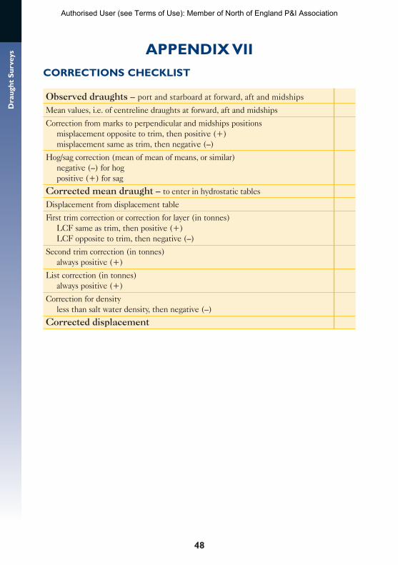
48
Dra
ught
Sur
veys APPENDIX VII
CORRECTIONS CHECKLIST
Observed draughts – port and starboard at forward, aft and midships
Mean values, i.e. of centreline draughts at forward, aft and midships
Correction from marks to perpendicular and midships positions misplacement opposite to trim, then positive (+) misplacement same as trim, then negative (–)
Hog/sag correction (mean of mean of means, or similar) negative (–) for hog positive (+) for sag
Corrected mean draught – to enter in hydrostatic tables
Displacement from displacement table
First trim correction or correction for layer (in tonnes) LCF same as trim, then positive (+) LCF opposite to trim, then negative (–)
Second trim correction (in tonnes) always positive (+)
List correction (in tonnes) always positive (+)
Correction for density less than salt water density, then negative (–)
Corrected displacement
Authorised User (see Terms of Use): Member of North of England P&I Association
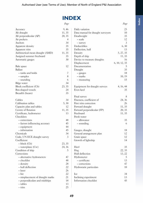
49
Ind
ex
Accuracy 9, 46Aft draught 11, 35Aft perpendicular (AP) 20, 35Air pockets 4Anchors 34Apparent density 35Apparent trim 35Arithmetical mean draught (AMD) 11, 35Assigned summer freeboard 35Automatic gauges 30
Bale space 12Ballast – tanks and holds 7 – samples 8 – sounding 6Bilge water 34Block coefficient (Cb) 23, 35Box-shaped vessels 24Breadth (beam) 35
Cables 34Calibration tables 5, 30Capacity plan and tables 12Centre of flotation 11, 35Certificate, hydrometer 13Checklists – corrections 48 – factors influencing accuracy 45 – equipment 44 – information 45Chemicals 34Code, UN ECE draught survey 3Coefficient – block (Cb) 23, 35 – waterplane (Cw) 24, 36Condition of ship 5Corrections – alternative hydrometers 47 – checklist 48 – density 28 – hull deflection 22 – layer 26 – list 22 – misplacement of draught marks 21 – perpendiculars and midships 18 – tables 13 – trim 25
Daily variation 23Data manual for draught surveyors 10Deadweight 35 – scale 12 – survey 3Deductibles 6, 30Deflection, hull 13Density 5, 27, 35Depth of ship 11, 35Device to measure draughts 16Displacement 6, 10, 12, 35Documentation 5Draught 35 – gauges 18 – marks 10, 19 – measuring 15
Equipment for draught surveys 4, 16, 44Even keel 35
Final survey 8Fineness, coefficient of 24, 36First trim correction 26Forward draught 11, 35Forward perpendicular (FP) 20, 35Freeboard 11, 35Fresh water – allowance 35 – sounding 6
Gauges, draught 18General arrangement plan 12Grain space 12Growth of lightship 14
Heel 35Hog 22, 35Hull deflection 13, 22Hydrometer 5 – certificate 13 – corrections 47Hydrostatic particulars 10
Ice 34Inclining experiment 13Information checklist 45
INDEXPagePage
Authorised User (see Terms of Use): Member of North of England P&I Association
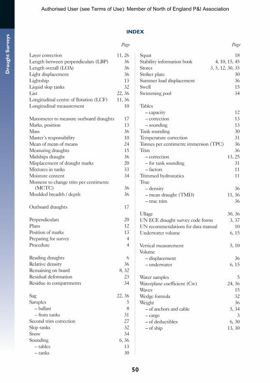
50
Dra
ught
Sur
veys
INDEX
PagePage
Layer correction 11, 26Length between perpendiculars (LBP) 36Length overall (LOA) 36Light displacement 36Lightship 13Liquid slop tanks 32List 22, 36Longitudinal centre of flotation (LCF) 11, 36Longitudinal measurement 10
Manometer to measure outboard draughts 17Marks, position 13Mass 36Master’s responsibility 10Mean of mean of means 24Measuring draughts 15Midships draught 36Misplacement of draught marks 20Mixtures in tanks 33Moisture content 34Moment to change trim per centimetre
(MCTC) 36Moulded breadth / depth 36
Outboard draughts 17
Perpendiculars 20Plans 12Position of marks 13Preparing for survey 4Procedure 4
Reading draughts 6Relative density 36Remaining on board 8, 32Residual deformation 23Residue in compartments 34
Sag 22, 36Samples 5 – ballast 8 – from tanks 31Second trim correction 27Slop tanks 32Snow 34Sounding 6, 36 – tables 13 – tanks 30
Squat 18Stability information book 4, 10, 15, 45Stores 3, 5, 12, 30, 35Striker plate 30 Summer load displacement 36Swell 15Swimming pool 34
Tables – capacity 12 – correction 13 – sounding 13Tank sounding 30Temperature correction 31Tonnes per centimetre immersion (TPC) 36Trim 36 – correction 13, 25 – for tank sounding 31 – factors 11Trimmed hydrostatics 11True – density 36 – mean draught (TMD) 11, 36 – true trim 36
Ullage 30, 36UN ECE draught survey code forms 3, 37UN recommendations for data manual 10Underwater volume 6, 15
Vertical measurement 5, 10Volume – displacement 36 – underwater 6, 15
Water samples 5Waterplane coefficient (Cw) 24, 36Waves 15Wedge formula 32Weight 36 – of anchors and cable 5, 34 – cargo 3 – of deductibles 6, 30 – of ship 13, 30
Authorised User (see Terms of Use): Member of North of England P&I Association
Draught SurveySa guIDe tO gOOD PraCtICeSecond edition
JIM DIBBLe, Peter MItCheLL and North of england P&I association
NORTH OF ENGLAND P&I ASSOCIATION
JIM
DIB
BLe,
Pet
er M
ItCh
eLL
aND
NO
rth
OF
eNg
LaN
D P&
I aSS
OCI
atIO
N
Dra
ug
ht
Surv
eyS
Sec
ond
editi
onDraught SurveyS a guIDe tO gOOD PraCtICe Second edition
by JIM DIBBLe, Peter MItCheLL and North of england P&I association
The accurate measurement of dry bulk cargoes by a vessel can minimise considerably the risk of shortage claims and disputes. This guide outlines the methods and corrections for a draught survey to be carried out to the required accuracy. It is designed to help surveyors and recommends procedures and formulas for every circumstance likely to be encountered during the conduct of draught surveys. The UN ECE draught survey forms have been included in an effort to achieve standardisation throughout the industry.
Jim Dibble is a master mariner with 50 years experience in the shipping industry. He spent 12 years at sea as a deck officer and 31 years in the marine education department at South Tyneside College, where he led the development of the Marine Simulation Centre. He has since worked as a marine consultant and is currently UK managing director of Seagull Maritime Information Technologies Ltd.
Peter Mitchell is a master mariner with 40 years experience in the shipping industry, firstly as a deck officer and then as a senior lecturer in the marine department at South Tyneside College, UK. He is now retired.
North of England P&I Association has offices in the UK, Greece, Hong Kong and Singapore and is one of the leading international mutual marine liability insurers with over 100 million GT of entered tonnage. Founded in 1860, the Association has long recognised the importance of providing practical loss prevention advice to its members, believing this to be the most effective way to reduce the number and scale of claims. The Association has developed a world-wide reputation for the quality and diversity of its loss prevention initiatives, which include this series of loss prevention guides co-authored with industry experts.
NORTH OF ENGLAND P&I ASSOCIATION
£30ISBN: 978-0-9558257-5-0
Authorised User (see Terms of Use): Member of North of England P&I Association