
Draper Platform Adaptation Bundle - RCI Engineering · Draper Platform Adaptation Bundle Intended...
40
Draper Platform Adaptation Bundle 7050-Series Self-Propelled Forage Harvester 900D-Series Draper Platform RC042050 Operator’s Manual Includes installation, operating, adjustment, technical, repair parts and safety instructions for the draper platform adaptation bundle. Retain this document for future reference. RCI Engineering LLC RC042070 (15Aug08) www.RCIengineering.com
Transcript of Draper Platform Adaptation Bundle - RCI Engineering · Draper Platform Adaptation Bundle Intended...

Draper Platform Adaptation Bundle7050-Series Self-Propelled Forage Harvester
900D-Series Draper Platform
RC042050
Operator’s Manual
Includes installation, operating, adjustment, technical, repair parts and safety instructions for the draper platform adaptation bundle.
Retain this document for future reference.
RCI Engineering LLCRC042070 (15Aug08)
www.RCIengineering.com

RCI Engineering LLCNew Attachments For Agricultural EquipmentWarranty Statement
RCI Engineering LLC, hereinafter referred to as RCI, warrants new RCI attachments, to the Original Retail Purchaser to be free from defects in material and workmanship for a period of one (1) year from the Date of Sale.
RCI Warranty Includes:
Genuine RCI parts costs required to repair or replace equipment at the selling dealer’s business loca-tion.
RCI MAKES NO REPRESENTATIONS OR WARRANTIES OF ANY KIND, EXPRESSED OR IMPLIED (INCLUDING THE IMPLIED WARRANTIES OF MERCHANTABILITY AND FITNESS FOR PARTICULAR PURPOSE), EXCEPT AS EXPRESSLY STATED IN THIS WARRANTY STATEMENT.
RCI WARRANTY DOES NOT INCLUDE:
1. Transportation to the selling dealer’s business location or, at the option of the Original Retail Purchaser, the cost of a service call.2. Freight costs above standard shipping costs for the replacement parts.3. Labor to make the repair or installation of the failed component. 4. Used equipment.5. Components covered by their own non-RCI warranties, such as tires and trade accessories.6. Repairs or adjustments caused by: improper use; non-intended use; failure to follow recommended maintenance procedures; use of unauthorized attachments; accident or other casualty.7. Liability for incidental or consequential damages of any type, including, but not limited to lost profits or expenses of acquiring replacement equipment or damage to machines to which the attachment is installed.
No agent, employee, or representative of RCI has any authority to bind RCI to any warranty except as specifically set forth herein. Any of these limitations excluded by local law shall be deemed deleted from this warranty; all other terms will continue to apply.
2

Draper Platform Adaptation BundleIntended Use:
This product is intended for use only with John Deere 900D-Series Draper Platforms and John Deere 7050-Series Self-Propelled Forage Harvesters to allow direct cut operations of small grains. The bundle features a larger-capacity hydraulic tank (increase of approximately 4.5 gallons) and reel speed and belt speed control from the cab.
IMPORTANT: Follow all safety guidelines and precautions as indicated in the 7050-Series SPFH Operator Manual and 900D-Series Draper Platform Operator Manual.
Table of Contents
Warranty..................................................................................................Page 2 Intended Use............................................................................................Page 3 Table of Contents.....................................................................................Page 31.0 Parts Listing.............................................................................................Page 42.0 Operation.................................................................................................Page 9 2.1 Hydraulic Operation................................................................................Page 9 2.2 Electrical Operation.................................................................................Page 103.0 Installation Instructions............................................................................Page 11 3.1 Hyrdraulic Reservoir Replacement..........................................................Page 11 3.2 Gear Pump Installation.............................................................................Page 12 3.3 Manifold Installation...............................................................................Page 15 3.4 Multi-Coupler Installation.......................................................................Page 16 3.5 Electrical Installation...............................................................................Page 23 3.6 Header Modifications..............................................................................Page 33
3

1.0 Parts Listing
The following pages include information regarding parts for the draper conversion bundle.
All parts are available from your local John Deere dealer.
Attention: Dealer - Contact RCI directly for all part orders for this bundle. In general, any part painted black is an RCI part. Any part painted green is a John Deere part.
4

Parts Listing - continued
5

Parts Listing - continued
66

Key Part Number Description QTY Comments2 RC042004 Clip 13 RC042005 Guard 14 RC042006 Valve, Hydraulic 15 RC042003 Holder 16 RC042028 Cover 17 RC042029 Seal 28 RC042033 Adapter 19 RC042034 Gear 1
10 RC042035 Ring, Snap 111 RC042036 Ring, Snap 112 RC042037 Shim 513 RC042038 Ring, Snap 114 RC042040 Bearing, Tapered Roller 115 RC042046 Tank, Hydraulic 116 RC042047 Pump, Gear 117 RC042051 Plug, Fitting 118 RC042052 Plug, Fitting 119 RC042053 Hose, Hydraulic 1 Pressure20 RC042054 Hose, Hydraulic 1 Suction21 RC042055 Hose, Hydraulic 1 Tank Return22 RC042056 Hose, Hydraulic 2 Header23 RC042057 Hose, Hydraulic 3 Quick Couplers- RC042075 Hose, Hydraulic 2 Belt Motor Extension
24 RC042071 Fitting, Tank Suction 125 RC042072 Fitting, Tank Return 126 RC042073 Fitting, Pump Suction 127 RC042074 Fitting, Pump Pressure 128 RC042083 Shield, Dust 329 RC042066 O-ring 330 RC042017 Coupler, Hydraulic 3 (A)31 RC042041 Assembly, Hydraulic Manifold 132 RC042065 Fitting 533 RC042059 Neck, Filler 134 RC042060 Clamp, Hose 135 RC042061 Hose, Hydraulic 136 RC042062 Line 137 RC042042 Driveline 138 RC042043 Connector, Wire Harness 1
Parts Listing - continued
7

Key Part Number Description Qty Comments40 RC042045 Controller, Proportional 141 RC042058 Potentiometer 142 RC042063 Switch, Reel Engage 143 RC042064 Switch, Belt Speed 1- RC042067 Grommet (3/4") 1- RC042068 Grommet (1/2") 1- RC042076 Wrap, Spiral 1- RC042077 Fitting, Adapter 2 For belt motor hose ext- RC042016 Decal 1- RC0153 Bushing 2- RC0154 Ring, Snap 1- RC0155 Screw, Rolling Thread 22- RC0156 Cover 8- RC0102 Stop - RCI 2- RC0104 Stop - SPFH 2- RC0120 Deflector 2- RC042084 Flighting, LH Auger 2- RC042085 Flighting, RH Auger 2- RC042069 Support 10- 0161822 Screw, M8 x 20 Flange head cap 1 Hyd Tank- 90701 Nut, M8 Flange 1 Hyd Tank- 0161832 Screw, M10 x 25 Flange Head Cap 2 Manifold- 0161821 Screw, M8 x 16 Flange Head Cap 4 Multi-Coupler- 63124 Band, Tie 25 Misc- 0161842 Screw, M12 x 30 Flange Head Cap 2 Gear Pump- 0161835 Screw, M10 x 40 Flange Head Cap 2 Header- 90702 Nut, M10 Flange 2 Header- 0154010 Bolt, M12 x 80 Gr. 10.9 1 Header- 40384 Washer, M10 Lock 1 Header- 0153640 Nut, M10 Gr. 10.9 1 Header- RC042070 Manual, Installation Instruction 1 Misc
A For service parts of components, see John Deere parts catalog for part number AZ19455
Parts Listing - continued
8

2.0 Operation
2.1 Hydraulic Operation
Hydraulic oil flows from the tank to the gear pump mounted at the engine. High pressure oil flows to the manifold, past a proportional flow control valve to the reel circuit of the draper plat-form. Return oil is routed back from the platform to the manifold to merge with the relief and bypass oil to return to the tank.
A functional diagram of the manifold is shown in Figure 1.
Figure 1. Functional Diagram of Manifold
9

2.2 Electrical Operation
Three switches are installed in the armrest. The first controls belt speed. The second controls engagement of the reel circuit. The third switch is the potentiometer that controls the reel speed.
To control draper belt speed, move the momentary toggle switch in the direction corresponding to the desired speed change.
To engage the reel, move the center toggle switch to the Engaged position.Note: When in Engaged position, the reel enable switch allows the forage harvester to automati-cally control the reel. The reel will turn in conjunction with the draper platform engagement and stop when the header is stopped.
IMPORTANT: Disengage the reel enable switch when the draper platform is not in use. Failure to do so will permit the draper circuit to operate at relief pressure against the multi-coupler.
To change reel speed, rotate the potentiometer dial in the direction corresponding to the desired change in speed.
The system is protected by a 10 amp fuse for the draper belt speed circuit and by the system fuses for the reel function control. The fuse is located in-line at “Board Three” in the electrical cabinet.
Figure 2. Wiring Diagram
10

3.0 Installation Instructions
3.1 Hydraulic Reservoir Replacement.
Drain and remove the hydraulic tank from the machine. Mark all hoses for installation in new tank upon completion of the change of tank Note: Machines not equipped with the Pro Drive Transmission require the installation of a fill tube and return line from the filter to the tank. All parts are included with the bundle. See parts diagram for component location information regarding the fill tank.
Note: Machines not equipped with the Pro Drive Transmission will require the installation of two plugs at the rear side of the tank. Plugs are included with the bundle.
Transfer all fittings from original tank to the new tank. Take care to remove all plugs and pre-vent trash from entering the new tank.
Install new hydraulic tank and all hydraulic lines. Inspect hose routings and adjust as necessary to prevent hoses rubbing on other components.
Install adapter fittings at remaining ports. These adapter fittings are included in the bundle. The larger fitting is for the suction port at the front of the tank. The smaller fitting is for tank return, at the rear of the tank.
See Figure 3 for more information.
Figure 3. Tank InstallationKey 1 - Tank Return Line for Draper Conversion
Key 2 - Plugs for Machines Without Pro-Drive Transmissions
11

3.2 Gear Pump Installation
Note: Due to tight clearances in the area of the auxiliary drive on the engine, the adapter and gear pump with fittings and pressure hose must be pre-assembled before installation on the ma-chine.
3.2.1 Assemble Adapter
Assemble auxiliary drive adapter. Refer to “SAE ‘B’ Rear Auxiliary Drive - Assemble Rear Auxiliary Drive Assembly” in the PowerTech Plus 6135 Base Engine Repair Manual. Compo-nents needed are included in this bundle.
3.2.2 Assembly Gear Pump to Adapter
Assemble gear pump to drive adapter. Install SAE “A” O-Ring at pump face and secure pump with two M12 x 30 Flange Head Cap Screws. Tighten hardware properly.
Install suction fitting and pressure fitting at pump.
See Figure 4 for details.
Figure 4. Gear Pump AssemblyKey 1 - Pressure Fitting Key 2 - M12 x 30 Screw Key 3 - O-ring LocationKey 4 - Drive Adapter Key 5 - Suction Fitting Key 6 - O-ring location
12

3.2.3 Remove Cover
Remove Cover at Auxiliary Drive port on engine.
Remove seal from cover and install at end of drive adapter (see Key 6, Figure 4).
Remove wiring clamp and hose clamp next to cover and relocate as shown in Figure 5. Manu-ally bend bracket for harness as needed.
IMPORTANT: Wiring must not contact any hoses upon completion.
Bend P-Clamp for wire harness behind pump location towards the engine block to permit clear-ance of gear pump upon install.
See Figure 5.
Figure 5. Hose and Electrical Relocation
Key 1 - Clamp to Move Key 2 - Clamp to InvertKey 3 - Clamp to Relocate and Manually Bend to Fit
Key 4 - Clamp to Form Towards Block for Clearance of Pump
13

3.2.4 Install Gear Pump
Install gear pump and drive adapter assembly at the auxiliary drive port on the engine.
Ensure that the O-Ring on the adapter at the port on the engine is in place during install.
Secure using the same bolts that held the cover in place. Orient the pump such that the suction is at the TOP of the pump.
Tighten hardware properly.
Install suction line and pressure line at the pump. Suction line is largest of hoses in diameter. Pressure line is the third longest hose with a 90-degree fitting on one end (for manifold end). Turn fittings towards front of machine upon install.
See Figure 6 for details.
Figure 6. Gear Pump InstallKey 1 - Gear Pump Key 2 - Suction Fitting Key 3 - Suction HoseKey 4 - Pressure Hose Key 5 - Pressure Fitting
14
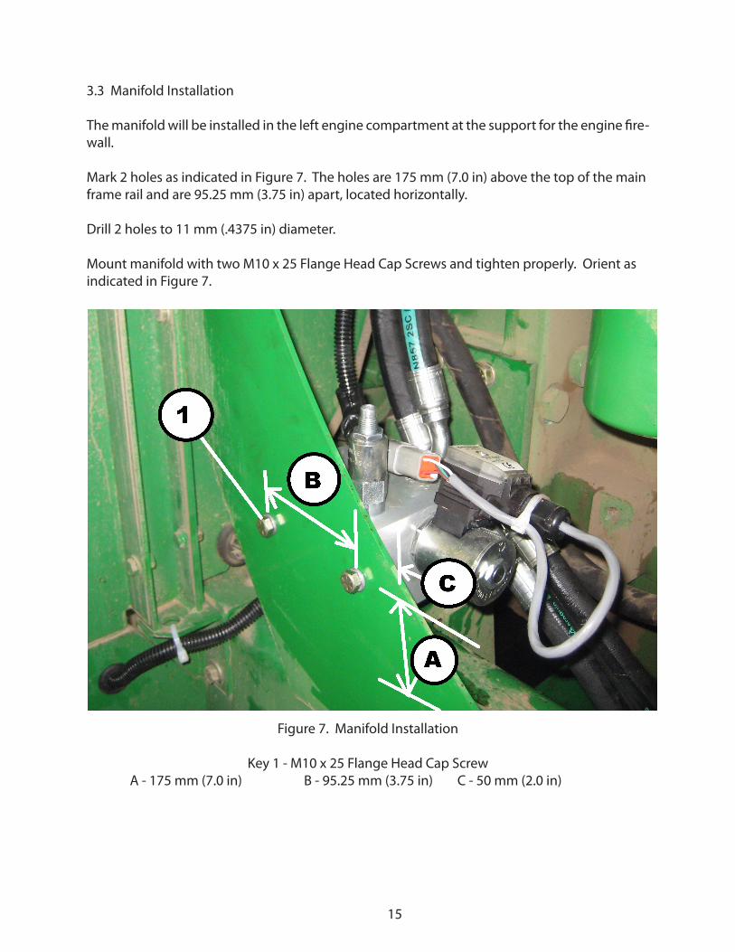
3.3 Manifold Installation
The manifold will be installed in the left engine compartment at the support for the engine fire-wall.
Mark 2 holes as indicated in Figure 7. The holes are 175 mm (7.0 in) above the top of the main frame rail and are 95.25 mm (3.75 in) apart, located horizontally.
Drill 2 holes to 11 mm (.4375 in) diameter.
Mount manifold with two M10 x 25 Flange Head Cap Screws and tighten properly. Orient as indicated in Figure 7.
Figure 7. Manifold Installation
Key 1 - M10 x 25 Flange Head Cap ScrewA - 175 mm (7.0 in) B - 95.25 mm (3.75 in) C - 50 mm (2.0 in)
15

3.4 Multi-Coupler Installation
3.4.1 Install Holder
Install holder on shield as shown in Figure 8.
Figure 8. Holder Installation
16

3.4.2 Install Multi-Coupler
Replace the top right fitting with the straight adapter included (-10 ORB male to -10 ORFS male).
Install the multi-coupler to the holder using the M8 x 16 Flange Head Cap Screws as indicated in Figure 9.
Figure 9. Multi-Coupler Installation
17

3.4.3 Install Quick Couplers and Hoses
Install the quick couplers as shown in Figure 10. Install caps on end of hose before coupler.
Install the hoses to the manifold. Route the hoses to the manifold along the hoses behind the left drive wheel as indicated in Figure 11.
Route the hoses over the pump stack together, along other hoses, back to the newly-installed manifold at the left side of the engine.
Install the hose at the top port of the multi-coupler to the top header port (Port H) at the new manifold. Install the hose from the bottom port of the multi-coupler to the return port (Port R) at the manifold.
IMPORTANT: The hydraulic oil lines must not contact the fuel line at the manifold.
Route hoses at manifold as indicated in Figure 12.
Figure 10. Quick Coupler and Hose Installation
18

Figure 11. Hose RoutingKey 1 - Return Hose Key 2 - Pressure Hose Key 3 - Tie Bands (multiple)
Figure 12. Manifold Hose RoutingKey 1 - Fuel Line Key 2 - Return Line Key 3 - Pressure Line
19

3.4.4 Route and attach auxiliary function hoses as shown in Figure 13.
Figure 13. Auxiliary Function HosesKey A - Tie Band Key B - Edge Protector Key C - Hose Key D - HoseKey E - Hose Key F - Hose Key G - Hose
20

3.4.5 Routing of Pump Hoses
Route pressure line from pump behind electrical harness along engine block as shown in Figure 14. Install hose wrap at area near corner to prevent contact of hose directly with brackets mounted on engine. Hose will be routed across the frame cross member (near tank mount) to opposite side of machine towards the manifold.
IMPORTANT: Route hoses around electrical wires. Hoses must not contact any wire harnesses upon completion of install.
Route suction line from pump between engine and frame to the top side of the new hy-draulic tank. Loop hose end to reach suction port on front side of tank.
Tighten all fittings properly.
Figure 14. Pump Hose RoutingKey 1 - Pressure Line Key 2 - Suction LineKey 3 - Wire Harness Key 4 - Hose Wrap
21

3.4.6 Hose Routing at Manifold
Route the pressure hose across the frame cross member behind the hydraulic tank to the mani-fold at the left side of the engine compartment. Secure hose to other hoses on the cross member using tie bands.
Install 90-degree end of hose to “P-Port” at manifold.
Route the tank return hose from the manifold to the open port at the rear of the hydraulic tank. The 90 degree hose fitting will be located at the manifold. Secure hoses together with tie bands.
See Figure 15.
Figure 15. Manifold Hose InstallationKey 1 - Pressure Hose
Key 2 - Tank Return HoseKey 3 - Tie Band
22

3.5 Electrical Installation
3.5.1 Wire Harness Installation
3.5.1.1 Start of Wire Harness.
Begin with the main wiring harness under the fuel tank, behind the transition.
Route the end with the fuse towards the new manifold, along the hoses. Route the end that leads to the multi-coupler through the hole in the LH panels under the cab, along the hoses for the reel. The “T” in the harness should be aligned just inside the compartment under the cab. Secure the wire harness to the RETURN line using tie bands. See Figure 16.
Figure 16. Wire Harness Above PumpKey 1 - Wire HarnessKey 2 - Return Line
Key 3 - Tie Band
23

3.5.1.2 Manifold Connection
Install Proportional Controller on Hydraulic Manifold. Route Harness through opening under the firewall support and connect the Proportional Controller. Secure the wire harness to the return line from the multi-coupler with a tie band. Do not fasten the wire harness to any other hoses. See Figure 17.
Figure 17. Manifold ConnectionKey 1 - Tie Band Location (Return Line)
Key 2 - Return LineKey 3 - Proportional Controller Connection
Key 4 - Opening below support
24

3.5.1.3 Electrical Cabinet Wiring
Remove plug from opening in storage compartment. Route harness through compartment hole and install large grommet over harness (cut grommet to install). Install tie band on wire harness to mounting hole on frame. See Figure 18.
Figure 18. Cabinet Wiring at Storage CompartmentKey 1 - Hole and Grommet
Key 2 - Tie BandInside the electrical cabinet, knock out the cover of the small hole in the bottom RH corner.
Route the wire harness into the electrical cabinet. Install the small grommet over the har-ness and install in the hole.
Install the ground wire on the ground terminal at board 3. Install the yellow wire with the fuse on the positive terminal at board 3.
Install the remaining blue wire with the terminal connector in connector 3X8, position 4. Secure harness with Tie Band. See Figure 19.
Figure 19. Cabinet WiringKey 1 - Power Wire Key 2 - Blue Wire (3X8, Pin 4) Key 3 - Tie Band Key 4 - Ground Wire Key 5 - Hole and Grommet
25

3.5.1.4 Routing of Harness to Multi-Coupler
Route front segment of wire harness along reel hoses to multi-coupler. Secure with tie bands to the reel return hose (bottom port of multi-coupler).
IMPORTANT: Do not secure wire harness to pressure line or other hydraulic hoses as vibration from pressure lines may damage wires inside conduit over time. See Figure 20.
Figure 20. Harness RoutingKey 1 - Return Line Key 2 - Harness
Key 3 - Tie Band Locations
Route harness along return line to multi-coupler. Install Deutsch Connector in the manifold us-ing snap ring labelled H175881 included in bundle.
Route long leg of harness with auxiliary lines to the RH fender. Install “676 Header” Connector on end of harness. Wire numbers are indicated below.
Brown Wire - Pin 7Green Wire - Pin 6Black Wire - Pin 2
26

Install connector at outlet. Secure wire harness to auxiliary line using tie bands across to the multi-coupler. See Figure 21.
Figure 21. Harness InstallationKey 1 - Wire Harness
Key 2 - Tie Bands
27

3.5.1.5 Routing of Harness to Cab
Return to area beneath fuel tank. Route the final leg of the harness from the “T” to the area in front of the transition.
Route the harness across the cross member below the cab to the RH side of the cab platform. The harness will exit the area behind the cab at the lower rear corner of the cab.
Secure the wire harness to the other harnesses with tie bands. See Figure 22.
Figure 22. Wire Harness in Front of TransitionKey 1 - Final Leg of Wire Harness
Key 2 - Main Harness Crossing FrameKey 3 - Transition
28

Remove the access panel at the RH side of the cab. Drill a 22 mm (7/8 in) diameter hole as indi-cated in Figure 23.
Figure 23. Hole Location
Install the wire harness through the new hole and tighten elbow fitting in place. Replace panel. See Figure 24.
Figure 24. Harness InstallationKey 1 - New Hole
Key 2 - Wire Harness
29

3.5.1.6 Routing of Harness in Cab
Route harness along armrest harness in cab.
Remove top of armrest by removing one screw at the armrest pad and three screws on the bottom of the armrest. Use caution to prevent damage to any components.
Secure harness to existing harness using tie bands. See Figure 25.
Figure 25. Wiring to ArmrestKey 1 - Tie Band
Key 2 - New HarnessKey 3 - Armrest Harness
30

3.5.2 Armrest Installation
Place decal on armrest in area indicated in Figure 26.
Drill 3 holes of 6mm (.25 in) diameter at the center of each hole in the decal.
Drill 2 holes at left side of decal out to 12mm (.5 in) for larger switches.
Figure 26. Armrest Installation PreparationKey 1 - Decal Key 2 - Pilot Hole/Switch Hole Key 3 - Mounting Screw Location (Removed)
Key 4 - 2 Holes to Drill to 12 mm (.5 in) Diameter
31

Install non-lighted switch at front hole.
Install lighted switch (mom on - off - mom on) at middle hole).
Install Potentiometer at rear hole.
See Figure 27.
Figure 27. Switch Installation
Wire switches per diagram in Figure 28. Reassemble armrest.
Figure 28. Wiring at Toggle Switches1 - Draper Belt Speed Switch 2 - Reel Enable Switch1A - Yellow 1-B Violet 1-C Gray 2A - Blue 2B - Red
32
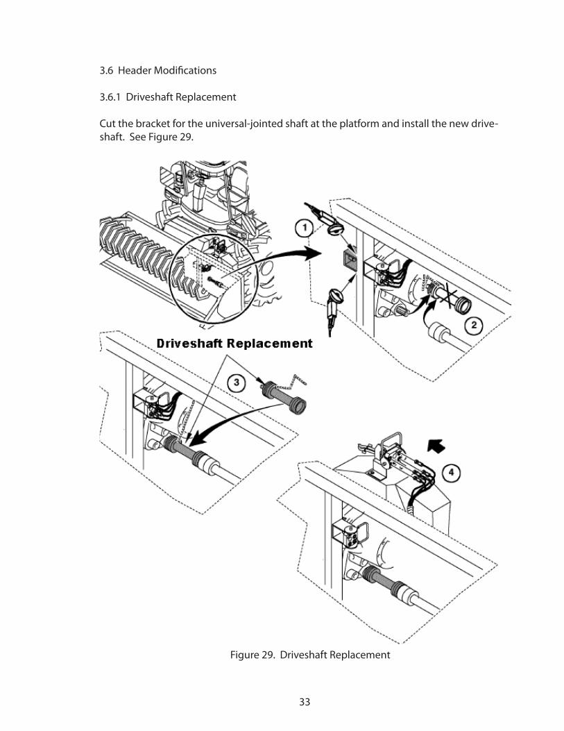
3.6 Header Modifications
3.6.1 Driveshaft Replacement
Cut the bracket for the universal-jointed shaft at the platform and install the new drive-shaft. See Figure 29.
Figure 29. Driveshaft Replacement
33

3.6.2 Modification of Adapting Frame Stops
Remove feedroll stops from adapting frame of SPFH. Remove welds around the base of the stop. Remove stops at both sides of the adapting frame. See Figure 30.
Figure 30. Stop RemovalKey 1 - Bolt for Removal Key 2 - Stop Key 3 - Welds to Remove
Drill new holes for the new stops included in the bundle. See Figure 31 for hole loca-tion. Mirror dimensions for opposite side. Hole diameter is 12mm (.5 in)
Repaint area as needed.
Figure 31. Hole Location
34

3.6.3 Installation of New Stops
Install new stops (smaller hole diameter of sets provided with bundle) using M10 x 40 Flange Bolts and Flange Nuts.
Reinstall adapting frame mounting bolts and washers using green bushings provided with bundle as indicated in Figure 32.
IMPORTANT: Additional frame stops are included with the bundle. Place these stops in the storage compartment for future use. These stops MUST be installed in place of the bushings when using a header other than the draper platform.
Tighten all hardware properly.
Figure 32. New Stop InstallationKey 1 - Bushing
Key 2 - M10 x 40 Flange Bolt and NutKey 3 - New Stop
35

3.6.4 Feeding Auger Change - OPTIONAL
This modification is considered optional and it may be beneficial to try the platform in the field in the operating conditions before making this change.
Remove fingers from the feeding auger as indicated in Figure 33.
Install a cover and M8 Self-Tapping Screw over each location as shown in Figure 34.
Figure 33. Auger Finger Removal Locations
Figure 34. Auger Tooth CoversKey 1 - Auger Tooth Cover Key 2 - M8 Screw
36

3.6.5 Relocation of Draper Belts - OPTIONAL
This modification is considered optional and it may be beneficial to try the platform in the field in the operating conditions before making this change.
Install 2 short extension hoses with -8 to -8 ORFS adapters at the RH draper belt drive as shown in Figure 35.
Figure 35. Hose Extensions
Remove the 3 attaching bolts for the transfer belt frame at the front plate of the frame. See Figure 36.
Figure 36. Bolt Removal37

Slide the draper transfer belt frames towards the center until they overlap the feeding auger by 23 cm (9 in). This will result in a distance between the belt rollers of approxi-mately 1120 cm (44 in). See Figure 37.
Figure 37. Overlap IndicationKey A - 1120 cm (9 in)
Drill 8.75 mm (11/32 in) diameter hole in center of slots for reinstallation of self-tapping bolts removed in previous step. Tighten all hardware properly. See Figure 38.
Figure 38. New Hole Locations
38

Hydraulic hoses for the LH belt drive motor can remain attached but must be pulled fur-ther from the frame approximately 50 mm (2 in) to accommodate the shift in the frame. See Figure 39.
Figure 39. Hoses for Adjustment
Install extension to crop deflector. Using existing and new hardware provided in bundle, install UHMW extensions over the top of the existing deflectors as shown in Figure 40.
Drill holes as needed in positions indicated in Figure 40. Tighten all hardware properly.
NOTE: If needed, the deflector can be pivoted up at the rear and new holes drilled in the end plate of the platform. This may be dependent on crop conditions.
Figure 40. Extension InstallationKey 1 - New HolesKey 2 - Deflector
Key 3 - Mounting to Existing Frame Hole39

3.6.6 Installation of Auger Flighting - OPTIONAL
This modification is considered optional and it may be beneficial to try the platform in the field in the operating conditions before making this change.
Install auger flighting on the feeding auger as indicated in Figure 41.
IMPORTANT: Remove all paint within 75mm (3 in) of weld-affected area before welding.
Two sections of flighting are used on each end of the auger, in order that it can be installed with the auger in the machine.
IMPORTANT: Isolate the area being welded from any other components, electrical or other-wise before welding.
Start the first segment of flighting approximately 10 cm (4 in) from the end of the feeding au-ger. Notch flighting as needed with a grinder to clear existing ribs on the feeding drum.
Weld the second segment to the end of the first when in position. Add gussets to the flighting as indicated, evenly spaced on each end. Weld with a stitch weld along the flighting.Repeat process on opposite end. Align start/stop points of flighting to balance the feeding auger as best as possible. Repaint as needed.
Figure 41. Auger Flighting Installation - Optional Key 1 - Flighting Key 2 - Gusset
40