Drainage Criteria Manual Vol. 2 - Colorado Springs, … Criteria Manual Vol. 2 City of Colorado...
134
Drainage Criteria Drainage Criteria Manual Vol. 2 Manual Vol. 2 City of Colorado Springs Engineering Division Stormwater Quality Policies, Procedures and Best Management Practices (BM P s)
Transcript of Drainage Criteria Manual Vol. 2 - Colorado Springs, … Criteria Manual Vol. 2 City of Colorado...
Drainage Criteria Drainage Criteria
Manual Vol. 2Manual Vol. 2
City of Colorado Springs
Engineering Division
Stormwater Quality Policies, Procedures
and Best Management Practices (BMPs)

Drainage Criteria Manual
Volume 2
May 2014
30 S. Nevada Ave.
Colorado Springs, Colorado 80901
www.springsgov.com
May 2014 City of Colorado Springs i-i
Drainage Criteria Manual, Volume 2
Drainage Criteria Manual
Volume 2
Contents
List of Abbreviations and Definitions ........................................................................................... i-1 to i-5
1.0 Stormwater Management and Planning ........................................................................ 1-1 to 1-18
2.0 BMP Selection ................................................................................................................... 2-1 to 2-18
3.0 Calculating the WQCV and Runoff Reduction ............................................................. 3-1 to 3-29
4.0 Treatment BMPs ................................................................................................................ 4-1 to 4-3
5.0 Source Control BMPs .................................................................................................................. 5-1
6.0 BMP Maintenance .............................................................................................................. 6-1 to 6-4
7.0 Construction BMPs .......................................................................................................... 7-1 to 7-44

i-1 City of Colorado Springs May 2014
Drainage Criteria Manual, Volume 2
List of Abbreviations > Greater Than
< Less Than
ASCE American Society of Civil Engineers
ASTM American Society for Testing and Materials
BOD Biochemical Oxygen Demand
BMPs Best Management Practices
CDPHE Colorado Department of Public Health and Environment
CDPS Colorado Discharge Permit System
cfs Cubic Feet Per Second
COD Chemical Oxygen Demand
CRS Colorado Revised Statutes
CUHP Colorado Urban Hydrograph Procedure
CWC Constructed Wetland Channel
CWCB Colorado Water Conservation Board
CWQCC Colorado Water Quality Control Commission
CWQCD Colorado Water Quality Control Division
DCIA Directly Connected Impervious Areas
DCM Drainage Criteria Manual
DO Dissolved Oxygen
DRCOG Denver Regional Council of Governments
DRURP Denver Regional Urban Runoff Program
EDB Extended Detention Basin
EMC Event Mean Concentration
EPA U.S. Environmental Protection Agency
ET Evapo-transpiration
EURV Excess Urban Runoff Volume
fps Feet per second
ft Feet
FHWA Federal Highway Administration
GB Grass Buffer
GS Grass Swale
H:V Horizontal to Vertical Ratio of a Slope
HSG Hydrologic Soil Group
i Impervious Ratio of a Catchment (Ia/100)
Ia Percent Imperviousness of Catchment
LEED Leadership in Energy and Environmental Design
LID Low Impact Development
MCM Minimum Control Measure
mg/L Milligrams per Liter
μg/L Micrograms per Liter
MDCIA Minimize Directly Connected Impervious Areas
MEP Maximum Extent Practicable
MS4 Municipal Separate Storm Sewer System
MSDS Material Safety Data Sheets
MWCOG Metropolitan Washington Council of Governments
N/A Not applicable

i-2 City of Colorado Springs May 2014
Drainage Criteria Manual, Volume 2
NPDES National Pollution Discharge Elimination System
NPV Net Present Value
NRCS Natural Resources Conservation Services
NTIS National Technical Information Service
NTU Nephelometric turbidity units
NURP Nationwide Urban Runoff Program
NVDPC Northern Virginia District Planning Commission
PA Porous Asphalt
PC Pervious Concrete
PICP Permeable Interlocking Concrete Pavers
PLD Porous Landscape Detention (term replaced by Bioretention in 2010 update)
PPS Pervious Pavement System
ppm Parts Per Million
RP Retention Pond
RPA Receiving Pervious Area
SCS Soil Conservation Service (now the NRCS)
SEWRPC Southeastern Wisconsin Regional Planning Commission
SF Sand Filter Extended Detention
SPA Separate Pervious Area
SWMM Stormwater Management Model (EPA)
SWMP Stormwater Management Plan
TOC Total Organic Carbon
TMDL Total Maximum Daily Load
TP Total Phosphorus
TSS Total Suspended Solids
UDFCD Urban Drainage and Flood Control District
UIA Unconnected Impervious Area
USCC United States Composting Council
USDCM Urban Storm Drainage Criteria Manual
USGS United States Geological Survey
WERF Water Environment Research Foundation
WQCV Water Quality Capture Volume
i-3 City of Colorado Springs May 2014
Drainage Criteria Manual, Volume 2
Definitions Best Management Practices (BMPs) - schedules of activities, prohibitions of practices, maintenance procedures,
and other management practices to prevent or reduce the pollution of State waters. BMPs also include treatment,
operating procedures, and practices to control site runoff, spillage or leaks, waste disposal, or drainage from
material storage. BMPs include structural and nonstructural controls.
City Engineer -the City Engineer or his/her designated representative.
Clean Water Act - the Federal Water Pollution Control Act (33 USC section 1251 et seq.), and any subsequent
amendments.
Construction activity - construction activity refers to ground surface disturbing activities, which include, but are
not limited to, clearing, grading, excavation, demolition, installation of new or improved haul roads and access
roads, staging areas, stockpiling of fill materials, and borrow areas. Construction does not include routine
maintenance to maintain original line and grade, hydraulic capacity, or original purpose of the facility.
Dedicated Asphalt Plants and Concrete Plants - portable asphalt plants and concrete plants that are located on or
adjacent to a construction site and that provide materials only to that specific construction site.
Earth Disturbance/Earth Disturbing Activity - a man-made alteration or disturbance of the ambient land
surface, natural cover or topography of land, including all grading, cut and fill, stockpiling of imported fill,
building, paving, landscaping and other activities which may result in, or contribute to, soil erosion or
sedimentation of the Waters of the State.
Erodibility -the susceptibility of a particular soil type to erosion by water or wind.
Erosion - the wearing away of the land surface by water, wind, ice or other geological agents, including the
detachment and movement of soil or rock fragments by water, wind, ice, gravity, or any combination thereof.
Erosion Control Measures -practices that slow or stop erosion.
Excess Urban Runoff Volume (EURV): EURV represents the difference between the developed and
pre-developed runoff volume for the range of storms that produce runoff from pervious land surfaces (generally
greater than the 2-year event).
Final Stabilization -when all earth disturbing activities at the site have been completed, and uniform vegetative
cover has been established with (for purposes of an Erosion and Stormwater Quality Control Permit) a density of
at least 70 percent of pre-disturbance levels and such cover is capable of adequately controlling soil erosion, as
determined by the City Engineer, or equivalent permanent, physical erosion reduction methods have been
employed. Also includes installation of permanent roads and structural stormwater quality BMPs and removal of
all temporary sediment controls.
Full Spectrum Detention: This practice utilizes capture and slow release of the EURV and better replicates
historic peak discharges for the full range of storm events compared to multi-stage detention practices (per
UDFCD).

i-4 City of Colorado Springs May 2014
Drainage Criteria Manual, Volume 2
Illicit Discharge - any discharge to a Municipal Separate Storm Sewer System (MS4) that is not composed
entirely of stormwater except for sources excluded in City Code.
Larger common plan of development or sale: a site where multiple separate and distinct construction
activities may be taking place at different times on different schedules.
Low Impact Development (LID): LID is a comprehensive land planning and engineering design approach to
managing stormwater runoff with the goal of mimicking the pre-development hydrologic regime. LID
emphasizes conservation of natural features and use of engineered, on-site, small-scale hydrologic controls that
infiltrate, filter, store, evaporate, and detain runoff close to its source. The terms Green Infrastructure and Better
Site Design are sometimes used interchangeably with LID.
LID Practice: LID practices are the individual techniques implemented as part of overall LID development or
integrated into traditional development, including practices such as bioretention, green roofs, permeable
pavements and other infiltration-oriented practices.
Mapping Unit - soil name and symbol given in the NRCS Soil Survey for each soil type. Most areas of the
Colorado Springs metropolitan area are included in a soil survey.
Maximum Extent Practicable (MEP): MEP is the statutory standard that establishes the level of pollutant
reductions that MS4 operators must achieve.Implementation of best management practices designed to control
stormwater runoff from the MS4 is generally the most appropriate and practicable approach for reducing
pollutants to satisfy the technology standard of MEP. This narrative standard does not currently include numeric
effluent limits. Minimizing Directly Connected Impervious Area (MDCIA): MDCIA includes a variety of runoff reduction
strategies based on reducing impervious areas and routing runoff from impervious surfaces over grassy areas to
slow runoff and promote infiltration. The concept of MDCIA has been recommended by UDFCD as a key
technique for reducing runoff peaks and volumes following urbanization. MDCIA is a key component of LID.
Municipal Separate Storm Sewer System (MS4) -a conveyance or system of conveyances (including roads with
drainage systems, municipal streets, catch basins, curbs, gutters, ditches, man-made channels, or storm drains)
owned or operated by a State, city, town, county, or other public body and designed or used for collecting or
conveying stormwater.
NPDES - as authorized by the Clean Water Act (CWA), the National Pollutant Discharge Elimination System
(NPDES) Permit Program controls water pollution by regulating point sources that discharge pollutants into
waters of the United States. Point sources are discrete conveyances such as pipes or man-made ditches.
Permanent -will remain in place for a long period of time (referring to a land-surface cover or erosion and
sediment control measure).
Runoff Coefficient - the fraction of total rainfall that will appear as runoff.
Sedimentation -the process of solid materials, both inorganic (mineral) and organic, coming to rest on the earth's
surface either above or below sea level.
i-5 City of Colorado Springs May 2014
Drainage Criteria Manual, Volume 2
Sediment -particulate solid material, either inorganic or organic, that will settle or be deposited in a liquid under
the force of gravity.
Source Control Measures - practices that control pollutants where they originate and reduce pollutants from
becoming entrained in stormwater
Stormwater - precipitation-induced surface runoff.
Stormwater Management – anything associated with the planning, maintenance, and regulation of facilities
which collect, store, treat or convey stormwater
Structural Controls - include facilities and structures which detain or retain stormwater or provide for infiltration
or evaporation of stormwater, for the purpose of or with the result of water quality enhancement.
Temporary -planned to be removed or inactivated after a period of time (referring to installation of erosion or
sediment control measures, either structural or nonstructural).
Treatment Train – a series of two or more stormwater treatment measures or BMPs
Waters of the State (State Waters) - any and all surface and subsurface waters which are contained in or flow in or
through this State, but does not include waters in sewage systems, waters in treatment works of disposal systems,
waters in potable water distribution systems, and all water withdrawn for use until use and treatment have been
completed. For the purposes of the MS4 permit, State Waters does not include subsurface waters.
Water Quality Capture Volume (WQCV): This volume represents runoff from frequent storm events such as
the 80th percentile storm. The volume varies depending on local rainfall data. Within the Colorado Springs
area, the WQCV is based on runoff from 0.6 inches of precipitation.
May 2014 City of Colorado Springs 1-i
Drainage Criteria Manual, Volume 2
Chapter 1
Stormwater Management and Planning
Contents
1.0 Overview/Purpose .................................................................................................................................... 1
2.0 Stormwater Quality Management .......................................................................................................... 1
2.1 Environmental Impacts of Runoff ......................................................................................................... 2
2.2 Stormwater Runoff Constituents and Sources ....................................................................................... 2
3.0 Stormwater Permit Regulations ............................................................................................................. 5
3.1 Clean Water Act Basics ......................................................................................................................... 5
3.2 Colorado's Stormwater Permitting Program .......................................................................................... 5
3.3 City of Colorado Springs MS4 Permit ................................................................................................... 6
3.4 Total Maximum Daily Loads and Stormwater Management ................................................................ 7
4.0 Four Step Process to Minimize Adverse Impacts of Urbanization ..................................................... 8
4.1 City of Colorado Springs MS4 Permit and Implementation of the Four-step Process ........................ 14
5.0 Stormwater BMPs: Onsite, Sub-regional and Regional ..................................................................... 14
6.0 Conclusion .............................................................................................................................................. 15
7.0 References ............................................................................................................................................... 16

Chapter 1 Stormwater Management and Planning
May 2014 City of Colorado Springs 1-1
Drainage Criteria Manual, Volume 2
1.0 Overview/Purpose
The Drainage Criteria Manual (DCM) – Volume 2, Stormwater Quality Policies, Procedures and Best
Management Practices is meant to provide owners, developers, engineers, and contractors with information they
will need to comply with local stormwater quality requirements for drainage planning/design relating to new
development/significant redevelopment and construction activities. The material in this manual is meant to
assist users in determining what requirements apply and what best management practices (“BMPs”) are
necessary for a given site. As with any manual, it is impossible to be all-inclusive: addressing every situation.
It is the owner’s responsibility to ensure that the work at the site is in compliance with all applicable statutes and
ordinances. This manual should be used in addition to other references and personal experience.
This manual covers the following areas:
1. Basics of stormwater quality and regulatory requirements.
2. Requirements for the development and implementation of an Erosion and Stormwater Quality Control
Plan.
3. Information on the use, design and maintenance of construction BMPs that can be used to comply with
the Erosion and Stormwater Quality requirements.
4. Information on construction inspection and enforcement.
5. Requirements and procedures for permanent/treatment stormwater quality BMPs in new
developments/significant redevelopments.
The stormwater quality criteria and requirements of this manual are meant to be in addition to the drainage
requirements and criteria listed in the Drainage Criteria Manual, Volume 1. If there are any conflicts or
discrepancies between the criteria and requirements of this manual and those in the Drainage Criteria Manual,
Volume 1, Engineering Criteria Manual or the City Engineering Standard Specifications, the criteria and
requirements in this manual take precedence.
The BMPs included in the Drainage Criteria Manual, Volume 2 are not meant to be comprehensive. It is
anticipated that as time goes on new technologies will be introduced as well as additional refinement of the
current technologies. It is expected that the list of BMPs will be expanded as time goes on. Should the
owner/engineer desire use of other temporary or permanent treatment BMPs, it will be necessary to submit
information that supports their use and ability to adequately control stormwater quality. These requests will be
reviewed on a case-by-case basis and follow procedures found in Chapters 4 and 7.
2.0 Stormwater Quality Management
Most of the public’s concerns with stormwater are usually related to flooding, not water quality. People complain
when their basements flood or roads become impassable and the public suffers when severe catastrophic floods
cause widespread damage to property and loss of life. Very few people are aware of the water quality impacts
that stormwater has on our rivers, streams, or lakes. Stormwater runoff quality can have significant impacts on
the receiving waters that affect not only the aquatic ecosystem, but also the quality of our communities.

Stormwater Management and Planning Chapter 1
1-2 City of Colorado Springs May 2014
Drainage Criteria Manual, Volume 2
2.1 Environmental Impacts of Runoff
Stormwater impacts streams by affecting the stream hydrology, stream morphology, water quality and aquatic
ecology. The extent of impact is related to the climate, land use, and the measures implemented to address the
impacts.
Briefly, the impacts on streams are:
Stream Hydrology: Urban development affects the environment through changes in the size and frequency
of storm runoff events, changes in base flows of the stream and changes in stream flow velocities during
storms results in decrease in travel time for runoff. Peak discharges and volumes in a stream can increase
from urbanization due to a decrease in infiltration of rainfall into the ground, loss of buffering vegetation and
resultant reduced evapotranspiration. This results in more surface runoff and larger loads of various
constituents found in stormwater.
Stream Morphology: When the hydrology of the stream changes, it can result in changes to the physical
characteristics of the stream. Such changes include streambed degradation, stream widening, and
streambank erosion. As the stream profile degrades and the stream tries to widen to accommodate higher
flows, instream bank erosion increases along with increases in sediment loads. These changes in the stream
bed also result in changes to the habitat of aquatic life.
Water Quality: Water quality is impacted through urbanization as a result of erosion during construction,
changes in stream morphology, and washing off of accumulated deposits on the urban landscape. Water
quality problems include turbid water, nutrient enrichment, bacterial contamination, organic matter loads,
metals, salts, temperature increases and increased trash and debris.
2.2 Stormwater Runoff Constituents and Sources
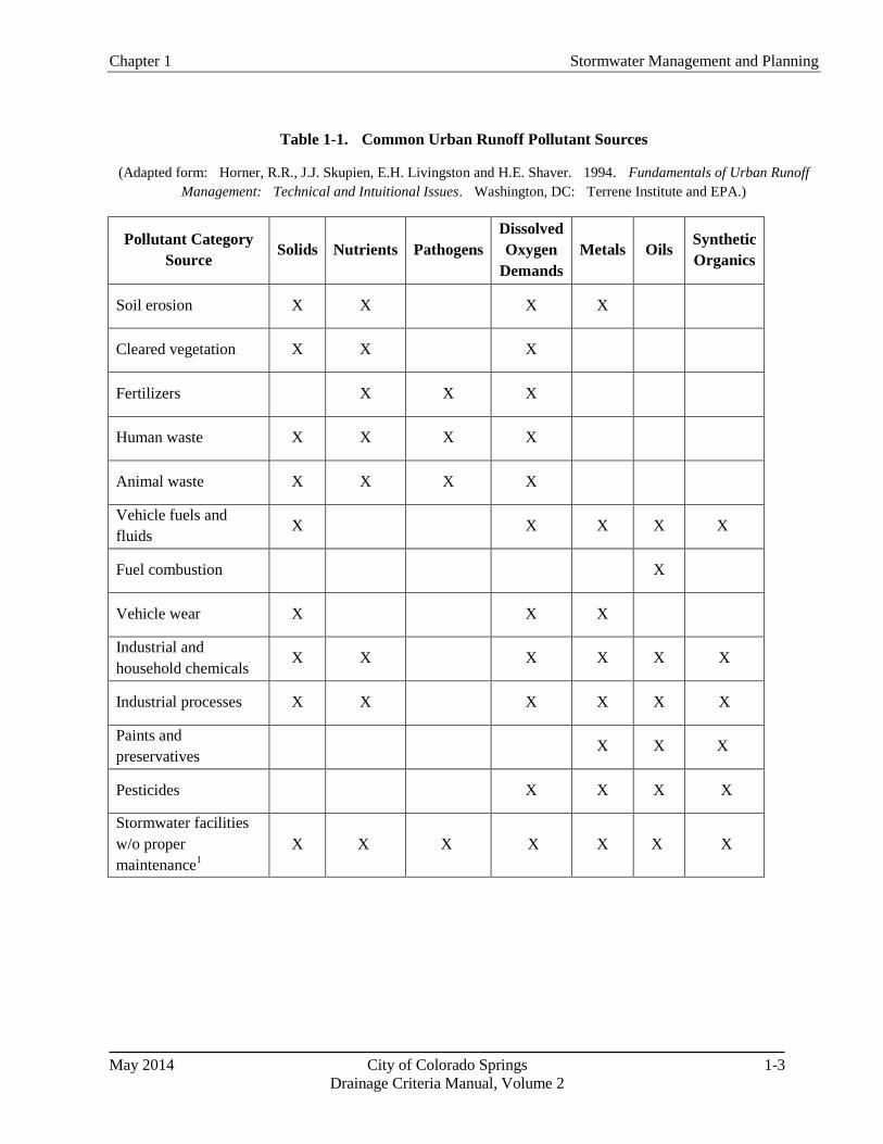
Urban runoff contains many types and forms of constituents as shown in Table 1-1; some occurring in higher
concentrations (see Table 1-2) than found in runoff before development and some that are not naturally present in
surface runoff from undeveloped land. Runoff from undeveloped watersheds contains sediment particles,
oxygen-demanding compounds, nutrients, metals, and other constituents. Once developed, constituent loads
increase because surface runoff volumes increase and the sources of many of these pollutants also increase.
Also, additional sources of constituents may exist in a catchment and find their way into runoff. They may
include the following:
• Metals, lubricating compounds, solvents, and other constituents originating from vehicles, machinery,
and industrial and commercial activities.
• Pesticides, herbicides, and fertilizers.
• Household solvents, paints, roofing materials, and other such materials.
• Pet litter, garbage, and other debris.
• Suspended solids washed off impermeable surfaces.
• Increased soil erosion during construction activities. Table 1-1 lists the common constituents in
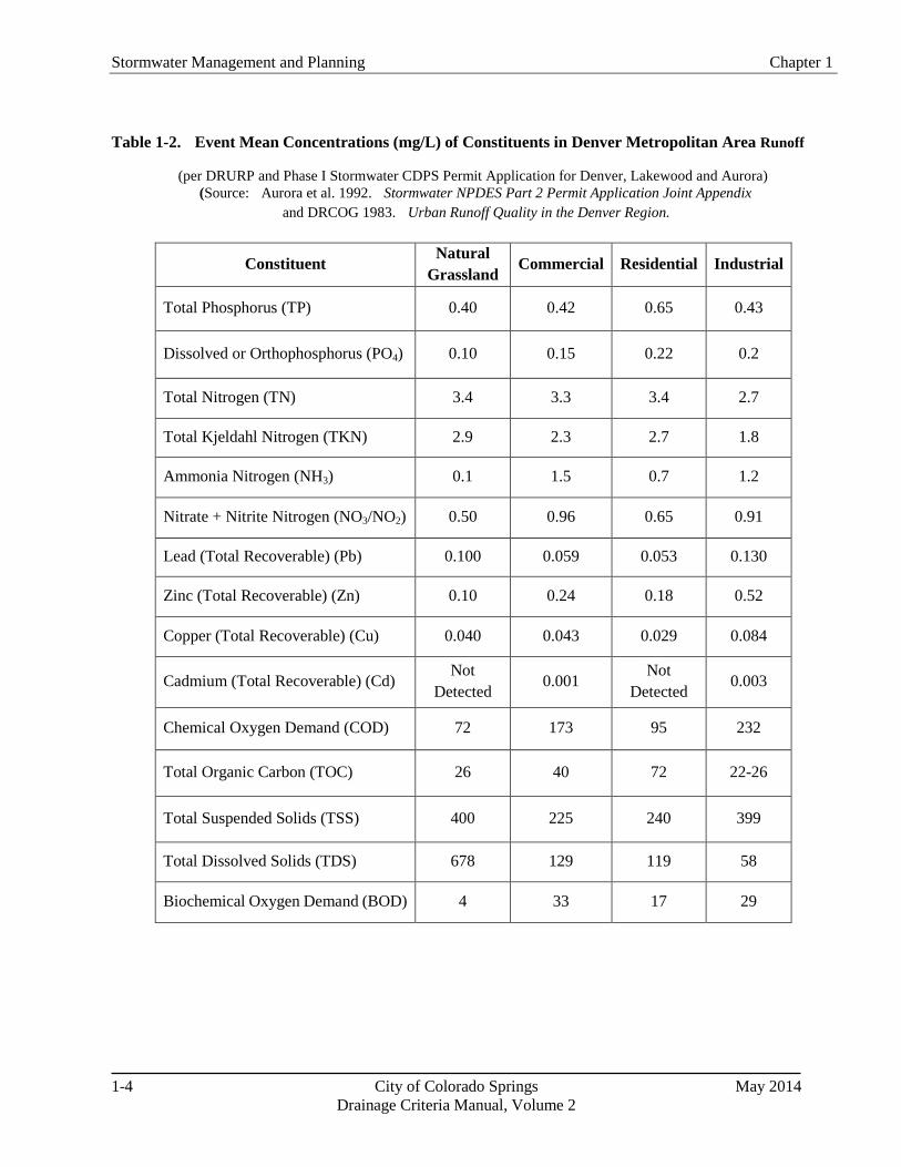
stormwater runoff and Table 1-2 lists event mean concentrations (mg/L) of constituents observed in a
metro Denver study (Colorado Springs information not available).
Chapter 1 Stormwater Management and Planning
May 2014 City of Colorado Springs 1-3
Drainage Criteria Manual, Volume 2
Table 1-1. Common Urban Runoff Pollutant Sources
(Adapted form: Horner, R.R., J.J. Skupien, E.H. Livingston and H.E. Shaver. 1994. Fundamentals of Urban Runoff
Management: Technical and Intuitional Issues. Washington, DC: Terrene Institute and EPA.)
Pollutant Category
Source Solids Nutrients Pathogens
Dissolved
Oxygen
Demands
Metals Oils Synthetic
Organics
Soil erosion X X X X
Cleared vegetation X X X
Fertilizers X X X
Human waste X X X X
Animal waste X X X X
Vehicle fuels and
fluids X X X X X
Fuel combustion X
Vehicle wear X X X
Industrial and
household chemicals X X X X X X
Industrial processes X X X X X X
Paints and
preservatives X X X
Pesticides X X X X
Stormwater facilities
w/o proper
maintenance1
X X X X X X X
Stormwater Management and Planning Chapter 1
1-4 City of Colorado Springs May 2014
Drainage Criteria Manual, Volume 2
Table 1-2. Event Mean Concentrations (mg/L) of Constituents in Denver Metropolitan Area Runoff
(per DRURP and Phase I Stormwater CDPS Permit Application for Denver, Lakewood and Aurora) (Source: Aurora et al. 1992. Stormwater NPDES Part 2 Permit Application Joint Appendix
and DRCOG 1983. Urban Runoff Quality in the Denver Region.
Constituent Natural
Grassland Commercial Residential Industrial
Total Phosphorus (TP) 0.40 0.42 0.65 0.43
Dissolved or Orthophosphorus (PO4) 0.10 0.15 0.22 0.2
Total Nitrogen (TN) 3.4 3.3 3.4 2.7
Total Kjeldahl Nitrogen (TKN) 2.9 2.3 2.7 1.8
Ammonia Nitrogen (NH3) 0.1 1.5 0.7 1.2
Nitrate + Nitrite Nitrogen (NO3/NO2) 0.50 0.96 0.65 0.91
Lead (Total Recoverable) (Pb) 0.100 0.059 0.053 0.130
Zinc (Total Recoverable) (Zn) 0.10 0.24 0.18 0.52
Copper (Total Recoverable) (Cu) 0.040 0.043 0.029 0.084
Cadmium (Total Recoverable) (Cd) Not
Detected 0.001
Not
Detected 0.003
Chemical Oxygen Demand (COD) 72 173 95 232
Total Organic Carbon (TOC) 26 40 72 22-26
Total Suspended Solids (TSS) 400 225 240 399
Total Dissolved Solids (TDS) 678 129 119 58
Biochemical Oxygen Demand (BOD) 4 33 17 29

Chapter 1 Stormwater Management and Planning
May 2014 City of Colorado Springs 1-5
Drainage Criteria Manual, Volume 2
3.0 Stormwater Permit Regulations
3.1 Clean Water Act Basics
The Federal Water Pollution Control Act of 1972, as amended (33 U.S.C. 1251 et seq.) is commonly known as
the Clean Water Act and establishes minimum stormwater management requirements for urbanized areas in the
United States. At the federal level, the EPA is responsible for administering and enforcing the requirements of
the Clean Water Act. Section 402(p) of the Clean Water Act requires urban and industrial stormwater be
controlled through the NPDES permit program. Requirements affect both construction and post-construction
phases of development. As a result, urban areas must meet requirements of Municipal Separate Storm Sewer
System (MS4) permits, and many industries and institutions such as state departments of transportation must also
meet NPDES stormwater permit requirements. MS4 permittees are required to develop a Stormwater
Management Program that includes measurable goals and to implement needed stormwater management
controls (i.e., BMPs). MS4 permittees are also required to assess controls and the effectiveness of their
stormwater programs and to reduce the discharge of pollutants to the "maximum extent practicable (MEP)."
Although it is not the case for every state, the EPA has delegated Clean Water Act authority to the State of
Colorado. The State must meet the minimum requirements of the federal program.
3.2 Colorado's Stormwater Permitting Program
The Colorado Water Quality Control Act (25-8-101 et seq., CRS 1973, as amended) established the Colorado
Water Quality Control Commission (CWQCC) within the Colorado Department of Public Health and
Environment (CDPHE) to develop water quality regulations and standards, classifications of state waters for
designated uses, and water quality control regulations. The Act also established the Colorado Water Quality
Control Division (CWQCD) to administer and enforce the Act and administer the discharge permit system,
among other responsibilities. Violations of the Act are subject to significant monetary penalties, as well as
criminal prosecution in some cases.
Colorado's stormwater management regulations have been implemented in two phases and are included in
Regulation No. 61 Colorado Discharge Permit System (CDPS) Regulations (CWQCC 2009). After the 1990
EPA "Phase I" stormwater regulation became effective, Colorado was required to develop a stormwater program
that covered specific types of industries and storm sewer systems for municipalities with populations of more
than 100,000. Phase I affected the City of Colorado Springs, Denver, Aurora, Lakewood, and the Colorado
Department of Transportation (CDOT). Phase 1 requirements included inventory of stormwater outfalls,
monitoring and development of municipal stormwater management requirements, as well as other requirements.
Construction activities disturbing five or more acres of land were required to obtain construction stormwater
discharge permits.
Phase II of Colorado's stormwater program was finalized in March 2001, establishing additional stormwater
permitting requirements. Two major changes included regulation of small municipalities (≥ 10,000 and
<100,000 population) in urbanized areas and requiring construction permits for sites disturbing one acre or more.
The Phase II regulation resulted in a large number of new permit holders including MS4 permits for El Paso
County, City of Fountain, Town of Monument, and City of Manitou Springs. In addition, there are also
non-standard MS4 permittees that include entities that are not cities or counties. Non-standard MS4 permittees
include entities such as Academy School District 20, Widefield School District 3, Pikes Peak Community
College, Harrison School District 2, Falcon School District 49, Cheyenne Mountain School District 12,
University of Colorado at Colorado Springs, and Colorado Springs School District 11. MS4 permit holders are
required to develop, implement, and enforce a CDPS Stormwater Management Program designed to reduce the
Stormwater Management and Planning Chapter 1
1-6 City of Colorado Springs May 2014
Drainage Criteria Manual, Volume 2
discharge of pollutants from the MS4 to the maximum extent practicable, to protect water quality, and to satisfy
the appropriate water quality requirements of the Colorado Water Quality Control Act (25-8-101 et seq., C.R.S.)
and the Colorado Discharge Permit Regulations (Regulation 61). Non-standard MS4 permittees may elect to
comply with their construction program and post-construction program requirements by following the
requirements of the City’s or County’s construction and post-construction programs.
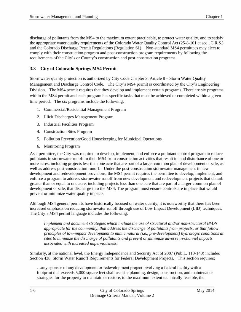
3.3 City of Colorado Springs MS4 Permit
Stormwater quality protection is authorized by City Code Chapter 3, Article 8 – Storm Water Quality
Management and Discharge Control Code. The City’s MS4 permit is coordinated by the City’s Engineering
Division. The MS4 permit requires that they develop and implement certain programs. There are six programs
within the MS4 permit and each program has specific tasks that must be achieved or completed within a given
time period. The six programs include the following:
1. Commercial/Residential Management Program
2. Illicit Discharges Management Program
3. Industrial Facilities Program
4. Construction Sites Program
5. Pollution Prevention/Good Housekeeping for Municipal Operations
6. Monitoring Program
As a permittee, the City was required to develop, implement, and enforce a pollutant control program to reduce
pollutants in stormwater runoff to their MS4 from construction activities that result in land disturbance of one or
more acres, including projects less than one acre that are part of a larger common plan of development or sale, as
well as address post-construction runoff. Under the post-construction stormwater management in new
development and redevelopment provisions, the MS4 permit requires the permittee to develop, implement, and
enforce a program to address stormwater runoff from new development and redevelopment projects that disturb
greater than or equal to one acre, including projects less than one acre that are part of a larger common plan of
development or sale, that discharge into the MS4. The program must ensure controls are in place that would
prevent or minimize water quality impacts.
Although MS4 general permits have historically focused on water quality, it is noteworthy that there has been
increased emphasis on reducing stormwater runoff through use of Low Impact Development (LID) techniques.
The City’s MS4 permit language includes the following:
Implement and document strategies which include the use of structural and/or non-structural BMPs
appropriate for the community, that address the discharge of pollutants from projects, or that follow
principles of low-impact development to mimic natural (i.e., pre-development) hydrologic conditions at
sites to minimize the discharge of pollutants and prevent or minimize adverse in-channel impacts
associated with increased imperviousness.
Similarly, at the national level, the Energy Independence and Security Act of 2007 (Pub.L. 110-140) includes
Section 438, Storm Water Runoff Requirements for Federal Development Projects. This section requires:
…any sponsor of any development or redevelopment project involving a federal facility with a
footprint that exceeds 5,000 square feet shall use site planning, design, construction, and maintenance
strategies for the property to maintain or restore, to the maximum extent technically feasible, the

Chapter 1 Stormwater Management and Planning
May 2014 City of Colorado Springs 1-7
Drainage Criteria Manual, Volume 2
predevelopment hydrology of the property with regard to the temperature, rate, volume, and duration of
flow.
The minimum measures required for development projects to satisfy the City’s MS4 permit requirements
are described in Section 4.1 of this chapter.
3.4 Total Maximum Daily Loads and Stormwater Management
Section 303(d) of the Clean Water Act requires states to develop a list of water bodies that are not attaining water
quality standards for their designated uses, and to identify relative priorities for addressing the impaired water
bodies. States must then develop Total Maximum Daily Loads (TMDLs) to assign allowable pollutant loads to
various sources to enable the water body to meet the designated uses established for that water body.
Implementation plans to achieve the loads specified under TMDLs commonly rely on BMPs to reduce pollutant
loads associated with stormwater sources.
In the context of this manual, it is important for designers, planners and other stormwater professionals to
understand TMDLs because TMDL provisions can directly affect stormwater permit requirements and BMP
selection and design. EPA provides this basic description of TMDLs:
A TMDL is a calculation of the maximum amount of a pollutant that a waterbody can receive and still
meet water quality standards, and an allocation of that load among the various sources of that pollutant.
Pollutant sources are characterized as either regulated stormwater, sometimes called "point sources"
that receive a waste load allocation (WLA), or nonpoint sources that receive a load allocation (LA).
Point sources include all sources subject to regulation under the NPDES program (e.g., wastewater
treatment facilities, most municipal stormwater discharges and concentrated animal feeding
operations). Nonpoint sources include all remaining sources of the pollutant, as well as anthropogenic
and natural background sources. TMDLs must also account for seasonal variations in water quality,
and include a margin of safety (MOS) to account for uncertainty in predicting how well pollutant
reductions will result in meeting water quality standards.
The TMDL calculation is:
Equation 1-1
Where:
WLA = the sum of waste load allocations (point sources),
LA = the sum of load allocations (nonpoint sources and background)
MOS = the margin of safety.
Although states are primarily responsible for developing TMDLs, EPA is required to review and approve or
disapprove TMDLs. EPA has developed a basic "TMDL Review Checklist" with the minimum recommended
elements that should be present in a TMDL document.
Once EPA approves a TMDL, there are varying degrees of impact to communities involved in the process,
generally differentiated among whether point sources or non-point sources of pollution are identified in the
TMDL. Permitted stormwater discharges are considered point sources. Essentially, this means that
wastewater or stormwater permit requirements consistent with waste load allocations must be implemented and
are enforceable under the Clean Water Act through NPDES permits.
Stormwater Management and Planning Chapter 1
1-8 City of Colorado Springs May 2014
Drainage Criteria Manual, Volume 2
If the MS4 permittee discharges into a waterbody with an approved TMDL that includes a
pollutant-specific waste load allocation under the TMDL, then the CWQCD can amend the permit to
include specific requirements related to that TMDL. For example, the permit may be amended to require
specific BMPs, and compliance schedules to implement the BMPs may be required. Numeric effluent
limits may also be incorporated under these provisions. TMDLs can have substantive effects on MS4
permit requirements. As an example, the City and County of Denver's MS4 permit has additional
requirements to control E. coli related to the E. coli TMDL approved for the South Platte River (Segment
14). Most stream segments in Colorado Springs are currently listed as impaired for E. coli. Information
on 303(d) listings and priorities for TMDL development can be obtained from the EPA and CWQCC
websites.
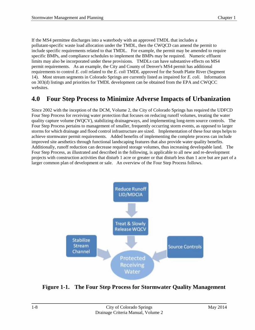
4.0 Four Step Process to Minimize Adverse Impacts of Urbanization
Since 2002 with the inception of the DCM, Volume 2, the City of Colorado Springs has required the UDFCD
Four Step Process for receiving water protection that focuses on reducing runoff volumes, treating the water
quality capture volume (WQCV), stabilizing drainageways, and implementing long-term source controls. The
Four Step Process pertains to management of smaller, frequently occurring storm events, as opposed to larger
storms for which drainage and flood control infrastructure are sized. Implementation of these four steps helps to
achieve stormwater permit requirements. Added benefits of implementing the complete process can include
improved site aesthetics through functional landscaping features that also provide water quality benefits.
Additionally, runoff reduction can decrease required storage volumes, thus increasing developable land. The
Four Step Process, as illustrated and described in the following, is applicable to all new and re-development
projects with construction activities that disturb 1 acre or greater or that disturb less than 1 acre but are part of a
larger common plan of development or sale. An overview of the Four Step Process follows.
Figure 1-1. The Four Step Process for Stormwater Quality Management

Chapter 1 Stormwater Management and Planning
May 2014 City of Colorado Springs 1-9
Drainage Criteria Manual, Volume 2
Step 1. Employ Runoff Reduction Practices
All land development and re-development activities that disturb 1 acre or more of property either individually or
in aggregate, are required to reduce runoff peaks, volumes, and pollutant loads from urbanizing areas, and to
implement LID strategies, including MDCIA. Runoff reduction estimates based on UDFCD-approved
calculation methods are required for all land development and re-development activities to quantify the volume
reduction achieved. For every site, including those smaller than 1 acre but part of a larger common plan of
development or sale, look for opportunities to route runoff through vegetated areas, where possible by sheet
flow. LID practices reduce unnecessary impervious areas and route runoff from impervious surfaces over
permeable areas to slow runoff (increase time of concentration) and promote infiltration. When LID/MDCIA
techniques are implemented throughout a development, the effective imperviousness is reduced, thereby
potentially reducing sizing requirements for downstream facilities. In addition, any reduction in runoff volume
can be deducted from the required WQCV for the site.
Key LID techniques include:
Conserve Existing Features: During the planning phase of development, identify portions of the site
that add value and should be protected or improved. Such areas may include mature trees, stream
corridors, wetlands, and NRCS Type A/B soils with higher infiltration rates. In order for this step to
provide meaningful benefits over the long-term, natural areas must be protected from compaction during
construction through the use of temporary construction fence or equivalent. In areas where disturbance
cannot practically be avoided, rototilling and soil amendments should be integrated to restore the
infiltration capacity of areas that will be restored with vegetation. Revegetation requirements and
additional guidance on site preparation is found in the DCM, Volume 1, Chapter 14 (Revegetation).
Minimize Impacts: Consider how the site lends itself to the desired development. In some cases,
creative site layout can reduce the extent of paved areas, thereby saving on initial capital cost of
pavement and then saving on pavement maintenance, repair, and replacement over time. Minimize
imperviousness, including constructing streets, driveways, sidewalks and parking lot aisles to the
minimum widths necessary, while still providing for parking, snow management, public safety and fire
access. When soils vary over the site, concentrate new impervious areas over NRCS Type C and D
soils, while preserving NRCS Type A and B soils for landscape areas and other permeable surfaces.
Maintaining natural drainage patterns, implementing sheet flow (as opposed to concentrated flow), and
increasing the number and lengths of flow paths will all reduce the impact of the development.
Stormwater Management and Planning Chapter 1
1-10 City of Colorado Springs May 2014
Drainage Criteria Manual, Volume 2
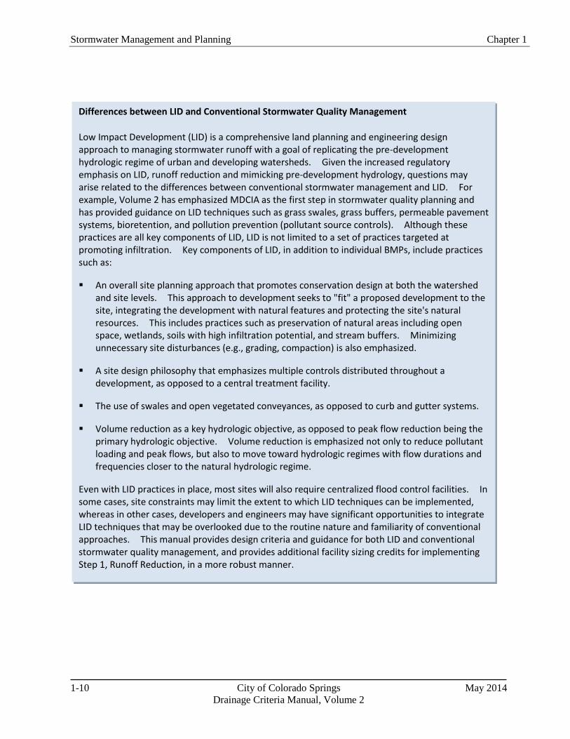
Differences between LID and Conventional Stormwater Quality Management
Low Impact Development (LID) is a comprehensive land planning and engineering design approach to managing stormwater runoff with a goal of replicating the pre-development hydrologic regime of urban and developing watersheds. Given the increased regulatory emphasis on LID, runoff reduction and mimicking pre-development hydrology, questions may arise related to the differences between conventional stormwater management and LID. For example, Volume 2 has emphasized MDCIA as the first step in stormwater quality planning and has provided guidance on LID techniques such as grass swales, grass buffers, permeable pavement systems, bioretention, and pollution prevention (pollutant source controls). Although these practices are all key components of LID, LID is not limited to a set of practices targeted at promoting infiltration. Key components of LID, in addition to individual BMPs, include practices such as:
An overall site planning approach that promotes conservation design at both the watershed and site levels. This approach to development seeks to "fit" a proposed development to the site, integrating the development with natural features and protecting the site's natural resources. This includes practices such as preservation of natural areas including open space, wetlands, soils with high infiltration potential, and stream buffers. Minimizing unnecessary site disturbances (e.g., grading, compaction) is also emphasized.
A site design philosophy that emphasizes multiple controls distributed throughout a development, as opposed to a central treatment facility.
The use of swales and open vegetated conveyances, as opposed to curb and gutter systems.
Volume reduction as a key hydrologic objective, as opposed to peak flow reduction being the primary hydrologic objective. Volume reduction is emphasized not only to reduce pollutant loading and peak flows, but also to move toward hydrologic regimes with flow durations and frequencies closer to the natural hydrologic regime.
Even with LID practices in place, most sites will also require centralized flood control facilities. In some cases, site constraints may limit the extent to which LID techniques can be implemented, whereas in other cases, developers and engineers may have significant opportunities to integrate LID techniques that may be overlooked due to the routine nature and familiarity of conventional approaches. This manual provides design criteria and guidance for both LID and conventional stormwater quality management, and provides additional facility sizing credits for implementing Step 1, Runoff Reduction, in a more robust manner.

Chapter 1 Stormwater Management and Planning
May 2014 City of Colorado Springs 1-11
Drainage Criteria Manual, Volume 2
Permeable pavement techniques and green roofs are
common LID practices that enhance infiltration and reduce
the impacts of paved areas and roofs:
o Permeable Pavement: The use of various permeable
pavement techniques as alternatives to paved areas can
significantly reduce site imperviousness.
o Green Roofs: Green roofs can be used to decrease
imperviousness associated with buildings and
structures. Benefits of green roofs vary based on
design of the roof. Research is underway to assess the
effectiveness of green roofs in Colorado's semi-arid
climate.
Minimize Directly Connected Impervious Areas
(MDCIA): Impervious areas should drain to pervious
areas. Use non-hardened drainage conveyances where
appropriate. Route downspouts across pervious areas, and
incorporate vegetation in areas that generate and convey
runoff. Three key BMPs include:
o Grass Buffers: Sheet flow over a grass buffer slows
runoff, encourages infiltration, and enhances sediment
removal, reducing effects of the impervious area.
o Grass Swales: Like grass buffers, use of grass swales
instead of hardened channels or storm sewers slows
runoff and promotes infiltration, also reducing the
effects of imperviousness.
o Bioretention (rain gardens): The use of distributed
on-site vegetated features such as rain gardens can help
maintain natural drainage patterns by allowing more
infiltration onsite. Bioretention can also treat the
WQCV, as described in the Four Step Process.
Historically, this critical volume reduction step has been
overlooked by planners and engineers, despite WQCV
reductions allowed based on MDCIA. In addition to
benefiting the environment through reduced hydrologic and
water quality impacts, volume reduction measures can also
have the added economic benefit to the developer of
increasing the area of developable land by reducing
required detention volumes and potentially reducing both
capital and maintenance costs.
Photograph 1-1. Permeable Pavement.
Permeable pavement consists of a permeable
pavement layer underlain by gravel and sand layers in
most cases. Uses include parking lots and low traffic
areas, to accommodate vehicles while facilitating
stormwater infiltration near its source. Photo courtesy
of Bill Wenk.
Photograph 1-2. Grass Buffer. This roadway
provides sheet flow to a grass buffer. The grass
buffer provides filtration, infiltration, and settling to
reduce runoff pollutants.
Photograph 1-3. Grass Swale. This densely
vegetated drainageway is designed with channel
geometry that forces the flow to be slow and shallow,
facilitating sedimentation while limiting erosion.
Stormwater Management and Planning Chapter 1
1-12 City of Colorado Springs May 2014
Drainage Criteria Manual, Volume 2
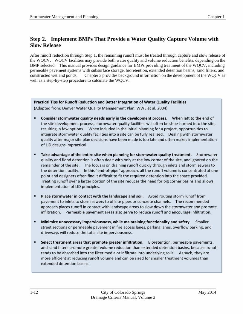
Practical Tips for Runoff Reduction and Better Integration of Water Quality Facilities
(Adapted from: Denver Water Quality Management Plan, WWE et al. 2004)
Consider stormwater quality needs early in the development process. When left to the end of the site development process, stormwater quality facilities will often be shoe-horned into the site, resulting in few options. When included in the initial planning for a project, opportunities to integrate stormwater quality facilities into a site can be fully realized. Dealing with stormwater quality after major site plan decisions have been made is too late and often makes implementation of LID designs impractical.
Take advantage of the entire site when planning for stormwater quality treatment. Stormwater quality and flood detention is often dealt with only at the low corner of the site, and ignored on the remainder of the site. The focus is on draining runoff quickly through inlets and storm sewers to the detention facility. In this "end-of-pipe" approach, all the runoff volume is concentrated at one point and designers often find it difficult to fit the required detention into the space provided. Treating runoff over a larger portion of the site reduces the need for big corner basins and allows implementation of LID principles.
Place stormwater in contact with the landscape and soil. Avoid routing storm runoff from pavement to inlets to storm sewers to offsite pipes or concrete channels. The recommended approach places runoff in contact with landscape areas to slow down the stormwater and promote infiltration. Permeable pavement areas also serve to reduce runoff and encourage infiltration.
Minimize unnecessary imperviousness, while maintaining functionality and safety. Smaller street sections or permeable pavement in fire access lanes, parking lanes, overflow parking, and driveways will reduce the total site imperviousness.
Select treatment areas that promote greater infiltration. Bioretention, permeable pavements, and sand filters promote greater volume reduction than extended detention basins, because runoff tends to be absorbed into the filter media or infiltrate into underlying soils. As such, they are more efficient at reducing runoff volume and can be sized for smaller treatment volumes than extended detention basins.
Step 2. Implement BMPs That Provide a Water Quality Capture Volume with
Slow Release
After runoff reduction through Step 1, the remaining runoff must be treated through capture and slow release of
the WQCV. WQCV facilities may provide both water quality and volume reduction benefits, depending on the
BMP selected. This manual provides design guidance for BMPs providing treatment of the WQCV, including
permeable pavement systems with subsurface storage, bioretention, extended detention basins, sand filters, and
constructed wetland ponds. Chapter 3 provides background information on the development of the WQCV as
well as a step-by-step procedure to calculate the WQCV.

Chapter 1 Stormwater Management and Planning
May 2014 City of Colorado Springs 1-13
Drainage Criteria Manual, Volume 2
Step 3. Stabilize Drainageways
During and following development, natural drainageways are often subject to bed and bank erosion resulting
from increases in frequency, duration, rate, and volume of runoff. Although Steps 1 and 2 help to minimize
these effects, drainageway stabilization that protects the bed and bank of the channel from these increases in
runoff is required. Many drainageways are included in basin master plans or major drainageway plans that
identify needed channel stabilization measures to accommodate developed flows. These measures not only
protect infrastructure such as utilities, roads and trails, but are also important to control sediment loading from
erosion of the channel itself, which can be a significant source of sediment and associated constituents, such as
phosphorus, metals and other naturally occurring constituents. If stream stabilization is implemented early in
the development process, it is far more likely that natural drainageway characteristics can be maintained with the
addition of grade control to accommodate future development. Targeted fortification of a relatively stable
drainageway is typically much less costly than repairing a degraded channel. The Drainage Criteria Manual,
Volume 1 provides requirements for channel stabilization, including stabilized natural channels and several
engineered channel approaches. This manual also describes a Constructed Wetland Channel approach, which
may provide additional water quality and community benefits. Brief descriptions of these three approaches to
stabilized channels include:
Stabilized Natural Channel. Natural drainageways in and adjacent to new developments usually receive
increased low flows due to urbanization even when upstream detention storage is provided. Urban
development causes channels to become destabilized disturbing riparian vegetation and habitat and
transporting sediment downstream. Therefore, some level of stream stabilization is always necessary.
Small grade control structures sized for low flows are often an effective means of establishing a mild slope
for the main channel and arresting stream degradation. Severe bends or cut banks may also need to be
stabilized. When site conditions are suitable Constructed Wetland Channels can be implemented. Wetland
bottoms use dense natural vegetation to slow runoff and promote settling and biological uptake. These are
particularly beneficial in treatment train approaches where pre-sedimentation occurs upstream of the wetland
channel. Such efforts to stabilize a natural waterway enhance aesthetics, riparian and stream habitat, and
water quality. Drainageway design should always be completed in accordance with master planning
documents when available.
Constructed Natural Channel. When upstream flood flows increase so that channel capacity
improvements are needed and sufficient right-of-way is available, constructed natural channels can provide
benefits similar to natural channels. These channels provide water quality benefits through infiltration and
pollutant uptake through vegetation. Grade control structures in these channels also reduce velocities and
prevent bed and bank erosion.
Engineered Channel: Engineered channels may be necessary when the upstream basin has developed
without detention storage or when adjacent properties are subject to flooding or erosion. These channels are
typically lined with rip-rap or cobblestone and do not enhance infiltration or water quality beyond the
reduction of bed and bank erosion.
All new and re-development projects are required to construct or participate in the funding of the construction of
the channel stabilization measures required by the applicable DBPS or master plan or needed to ensure channel
stability. Developers shall be required to show that DBPS recommendations for stabilized or constructed
natural channels are not feasible before engineered channels are proposed.

Stormwater Management and Planning Chapter 1
1-14 City of Colorado Springs May 2014
Drainage Criteria Manual, Volume 2
Whereas flood control is
best handled on a
regional basis,
stormwater quality is
best managed as a
resource and distributed
throughout the site.
Step 4. Implement Site Specific and Other Source Control BMPs
Site specific needs such as material storage or other site operations require targeted source control BMPs. This
is often the case for new development or significant redevelopment of an industrial or commercial site. Chapter
5 includes information on source control practices such as covering storage/handling areas and spill containment
and control. All new and re-development that includes outdoor storage or the potential for the introduction of
contaminants to the City’s MS4 shall be required to implement site specific and/or source control BMPs to
protect receiving waters.
4.1 City of Colorado Springs MS4 Permit and Implementation of the Four-step Process
The entire Four-Step Process is required for all land distrurbance activities greater than 1 acre or less than an acre
if part of a larger common plan of development or sale. Implementing runoff reduction methods as described in
Step 1 is an effective means of providing water quality treatment and must be implemented and quantified in
order to contribute to the requirements described in Step 2. Source controls described in Step 4 may also be
required under permits issued by other agencies.
5.0 Stormwater BMPs: Onsite, Sub-regional and Regional
Stormwater BMPs are required to be implemented as close to the source
as practicable, resulting in smaller BMPs (in parallel or in series) that are
distributed throughout a site or subbasin. Whereas flood control is best
handled on a regional basis, stormwater quality is best managed when
stormwater is viewed as a resource and distributed throughout the site.
Although not preferred, WQCV facilities may be implemented
regionally (serving a drainageway with a drainage area between 130
acres and 640 acres, one square mile) in accordance with an approved
drainage master planning study. Subregional (serving two or more
development parcels with a total drainage area less than 130 acres)
implementation is preferred, as this strategy protects State Waters in
compliance with the City’s MS4 permit. Drainage master plans must
be consulted to determine if regional or subregional facilities are already
planned or in place for new developments or redevelopments.
Life-cycle costs of onsite, subregional, and regional facilities, including
long-term maintenance responsibilities, must also be part of the decision-making process when selecting the
combinations of facilities and channel improvements needed to serve a development or redevelopment.
Potential benefits of subregional facilities include consolidated maintenance efforts, economies of scale for
larger facilities as opposed to multiple onsite WQCV facilities, and potential integration with flood control
facilities. In addition, sub-regional storage-based facilities may be beneficial in areas where onsite BMPs are
not feasible due to geotechnical or land use constraints or when retrofitting an existing flood control facility in a
fully developed watershed.
The most common challenges regarding regional facilities relate to protection of State Waters and the timing of
funding for construction of the facilities. Often, regional facilities are funded by revenues collected from new
development activities. New developments (and revenues) are required to fund construction of the water
quality facility, but the water quality facility is needed upfront to provide protection for new development. This
timing problem can be solved by constructing onsite water quality facilities for new development that occur
before a regional facility is in place. These onsite BMPs may be temporary in that they can be converted to
developable land once the regional facility is constructed.
Chapter 1 Stormwater Management and Planning
May 2014 City of Colorado Springs 1-15
Drainage Criteria Manual, Volume 2
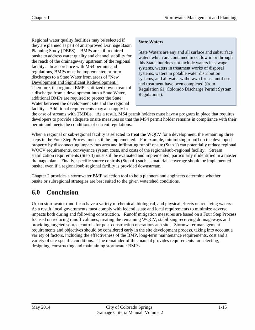
State Waters
State Waters are any and all surface and subsurface
waters which are contained in or flow in or through
this State, but does not include waters in sewage
systems, waters in treatment works of disposal
systems, waters in potable water distribution
systems, and all water withdrawn for use until use
and treatment have been completed (from
Regulation 61, Colorado Discharge Permit System
Regulations).
Regional water quality facilities may be selected if
they are planned as part of an approved Drainage Basin
Planning Study (DBPS). BMPs are still required
onsite to address water quality and channel stability for
the reach of the drainageway upstream of the regional
facility. In accordance with MS4 permits and
regulations, BMPs must be implemented prior to
discharges to a State Water from areas of "New
Development and Significant Redevelopment."
Therefore, if a regional BMP is utilized downstream of
a discharge from a development into a State Water,
additional BMPs are required to protect the State
Water between the development site and the regional
facility. Additional requirements may also apply in
the case of streams with TMDLs. As a result, MS4 permit holders must have a program in place that requires
developers to provide adequate onsite measures so that the MS4 permit holder remains in compliance with their
permit and meets the conditions of current regulations.
When a regional or sub-regional facility is selected to treat the WQCV for a development, the remaining three
steps in the Four Step Process must still be implemented. For example, minimizing runoff on the developed
property by disconnecting impervious area and infiltrating runoff onsite (Step 1) can potentially reduce regional
WQCV requirements, conveyance system costs, and costs of the regional/sub-regional facility. Stream
stabilization requirements (Step 3) must still be evaluated and implemented, particularly if identified in a master
drainage plan. Finally, specific source controls (Step 4 ) such as materials coverage should be implemented
onsite, even if a regional/sub-regional facility is provided downstream.
Chapter 2 provides a stormwater BMP selection tool to help planners and engineers determine whether
onsite or subregional strategies are best suited to the given watershed conditions.
6.0 Conclusion
Urban stormwater runoff can have a variety of chemical, biological, and physical effects on receiving waters.
As a result, local governments must comply with federal, state and local requirements to minimize adverse
impacts both during and following construction. Runoff mitigation measures are based on a Four Step Process
focused on reducing runoff volumes, treating the remaining WQCV, stabilizing receiving drainageways and
providing targeted source controls for post-construction operations at a site. Stormwater management
requirements and objectives should be considered early in the site development process, taking into account a
variety of factors, including the effectiveness of the BMP, long-term maintenance requirements, cost and a
variety of site-specific conditions. The remainder of this manual provides requirements for selecting,
designing, constructing and maintaining stormwater BMPs.

Stormwater Management and Planning Chapter 1
1-16 City of Colorado Springs May 2014
Drainage Criteria Manual, Volume 2
7.0 References
American Society of Civil Engineers and Water Environment Federation. 1992. Design and Construction of
Urban Stormwater Management Systems. ASCE Manual and Reports of Engineering Practice No. 77
and WEF Manual of Practice FD-20. Alexandria, VA: WEF.
Burton, A. and R. Pitt. 2001. Stormwater Effects Handbook: A Toolbox for Watershed Managers, Scientists,
and Engineers. Lewis Publishers.
http://www.epa.gov/ednnrmrl/publications/books/handbook/index.htm
Center for Watershed Protection Website: http://www.cwp.org
City of Aurora Utilities Department, City of Denver Department of Public Works, City of Lakewood Department
of Planning, Permits and Public Works in cooperation with Urban Drainage and Flood Control District.
1992. Stormwater NPDES Part 3 Permit Application Joint Appendix.
Colorado Water Quality Control Division (WQCD) Website: http://www.cdphe.state.co.us/wq
Colorado Water Quality Control Division (WQCD). 2009. Authorization to Discharge under the Colorado
Discharge Permit System, Permit No. COS-000001, City and County of Denver MS4 Permit.
Colorado Water Quality Control Commission (WQCC). 2009. Regulation No. 61 Colorado Discharge Permit
System (CDPS) Regulations.
Colorado Water Quality Control Division (WQCD). 2008. MS4 General Permit. Permit No. COR-090000.
CDPS General Permit, Stormwater Discharges Associated with Municipal Separate Storm Sewer
Systems (MS4s), Authorization to Discharge under the Colorado Discharge Permit System.
Debo, T. and A. Reese. 2002. Municipal Stormwater Management. 2nd
Edition. Lewis Publishers: Boca
Raton, FL.
Denver Regional Council of Governments (DRCOG). 1983. Urban Runoff Quality in the Denver Region.
Denver, CO.
Driscoll, E., G. Palhegyi, E. Strecker, and P. Shelley. 1990. Analysis of Storm Event Characteristics for
Selected Rainfall Gauges Throughout the United States. Prepared for the U.S. Environmental
Protection Agency, Woodward-Clyde Consultants: Oakland, CA.
U.S. Environmental Protection Agency (EPA) Stormwater Program Website:
http://cfpub.epa.gov/npdes/home.cfm?program_id=6
U.S. Environmental Protection Agency (EPA). 2009. Federal Register Notice Regarding Stakeholder Input;
Stormwater Management Including Discharges from New Development and Redevelopment. Federal
Register, Vol. 74, No. 247, 68617-68622.

Chapter 1 Stormwater Management and Planning
May 2014 City of Colorado Springs 1-17
Drainage Criteria Manual, Volume 2
U.S. Environmental Protection Agency (EPA). 2005. Stormwater Phase II Final Rule: Small Construction
Program Overview. Fact Sheet 3.0. Office of Water.
http://www.epa.gov/region8/water/stormwater/pdf/fact3-0.pdf
U.S. Environmental Protection Agency (EPA). 1983. Results of the Nationwide Urban Runoff Program,
Volume 1 – Final Report. U.S. Environmental Protection Agency, Water Planning Division,
Washington D.C.
Horner, R.R., J.J. Skupien, E.H. Livingston and H.E. Shaver. 1994. Fundamental of Urban Runoff
Management: Technical and Institutional Issues. Terrene Institute and EPA: Washington D.C.
International Stormwater Best Management Practices Database. www.bmpdatabase.org. Cosponsored by the
Water Environmental Research Foundation, American Society of Civil Engineers, Environmental and
Water Resources Institute, Federal Highway Administration and U.S. Environmental Protection
Agency. Accessed in 2010.
Low Impact Development (LID) Center Website: http://www.lid-stormwater.net/
National Research Council. 2008. Urban Stormwater Management in the United States. National
Academies Press. http://www.epa.gov/npdes/pubs/nrc_stormwaterreport.pdf
Oregon State University et al. 2006. Evaluation of Best Management Practices for Highway Runoff Control.
Transportation Research Board. NCHRP-565. Corvallis, OR.
http://www.trb.org/news/blurb_detail.asp?id=7184
Pitt, R., A. Maestre, H. Hyche, and N. Togawa. 2008. The Updated National Stormwater Quality Database,
Version. Proceedings of the Water Environment Federation Technical Exposition and Conference.
Chicago, IL.
Pitt, R., A. Maestre, and R. Morquecho. 2004. The National Stormwater Quality Database (NQSD), Version
1.1. University of Alabama: Tuscaloosa, AL.
Roesner, L.A. and B.P. Bledsoe. 2003. Physical Effects of Wet Weather Flows on Aquatic Habitats. Water
Environment Research Foundation: Alexandria, VA. Co-published by IA Publishing: United
Kingdom.
Shaver, E. R. Horner, J. Skupien, C. May, and G. Ridley. 2007. Fundamental of Urban Runoff Management:
Technical and Institutional Issues, Second Edition. U.S. Environmental Protection and North
American Lake Management Society.
Urbonas, B. and J. Doerfer. 2003. Some Observations on Atmospheric Dust Fallout in the Denver, Colorado
Area of the United States. Flood Hazard News. Urban Drainage and Flood Control District: Denver,
CO.

Stormwater Management and Planning Chapter 1
1-18 City of Colorado Springs May 2014
Drainage Criteria Manual, Volume 2
Urbonas, B., Guo, J., and L.S. Tucker. 1989. Sizing Capture Volume for Storm Water Quality Enhancement.
Flood Hazard News. Urban Drainage and Flood Control District: Denver, CO.
Water Environment Federation and American Society of Civil Engineers. 1998. Urban Runoff Quality
Management, WEF Manual of Practice No. 23 and ASCE Manual and Report on Engineering Practice
N0; 87. Water Environment Federation (WEF): Alexandria, VA.
Watershed Management Institute. 1997. Operation, Maintenance and Management of Stormwater
Management Systems. Watershed Management Institute: Ingleside, MD.

May 2014 City of Colorado Springs 2-i
Drainage Criteria Manual, Volume 2
Chapter 2
BMP Selection
Contents
1.0 BMP Selection ................................................................................................................................... 1 1.1 Physical Site Characteristics ...................................................................................................................... 1 1.2 Space Constraints ...................................................................................................................................... 2 1.3 Targeted Pollutants and BMP Processes ................................................................................................... 3 1.4 Storage-Based Versus Conveyance-Based ................................................................................................ 8 1.5 Runoff Reduction ...................................................................................................................................... 8 1.6 Pretreatment ............................................................................................................................................... 9 1.7 Treatment Train ......................................................................................................................................... 9 1.8 Online Versus Offline Facility Locations ................................................................................................ 10 1.9 Integration with Flood Control ................................................................................................................ 10
1.9.1 Sedimentation BMPs ................................................................................................................... 11 1.9.2 Infiltration/Filtration BMPs ......................................................................................................... 11
1.10 Land Use, Compatibility with Surroundings, and Safety ........................................................................ 11 1.11 Maintenance and Sustainability ............................................................................................................... 12 1.12 Costs ........................................................................................................................................................ 12
2.0 BMP Selection Tool ........................................................................................................................ 12
3.0 Life Cycle Cost and BMP Performance Tool ............................................................................... 16 3.1 BMP Whole Life Costs ............................................................................................................................ 16 3.2 BMP Performance ................................................................................................................................... 17 3.3 Cost Effectiveness ................................................................................................................................... 17
4.0 Conclusion ....................................................................................................................................... 17
5.0 References ....................................................................................................................................... 18
Figures
Figure 2-1. BMP Decision Tree for Highly Urbanized Sites ..................................................................... 13 Figure 2-2. BMP Decision Tree for Conventional Development Sites...................................................... 14 Figure 2-3. BMP Decision Tree for Linear Construction in Urbanized Areas .......................................... 15
Tables
Table 2-1. Primary, Secondary and Incidental Treatment Process Provided by BMPs ............................... 5 Table 2-2. BMP Effluent EMCs (Source: International Stormwater BMP Database,August 2010) ......... 6

Chapter 2 BMP Selection
May 2014 City of Colorado Springs 2-1
Drainage Criteria Manual, Volume 2
1.0 BMP Selection
This chapter provides requirements for selecting BMPs for all new development or redevelopment
projects for which construction activities disturb greater than or equal to 1 acre, including projects less
than 1 acre that are part of a larger common plan of development or sale. These requirements are to be
incorporated into qualifying development projects during the planning phase of a project. BMP selection
involves many factors such as physical site characteristics, treatment objectives, aesthetics, safety,
maintenance requirements, and cost. Typically, there is not a single answer to the question of which BMP
(or BMPs) should be selected for a site; there are usually multiple solutions ranging from stand-alone
BMPs to treatment trains that combine multiple BMPs to achieve the water quality objectives. Factors
that must be considered when selecting BMPs are the focus of this chapter.
1.1 Physical Site Characteristics
The first step in BMP selection is identification of physical characteristics of a site including topography,
soils, contributing drainage area, groundwater, baseflows, wetlands, existing drainageways, and
development conditions in the tributary watershed (e.g., construction activity). A fundamental concept of
Low Impact Development (LID) is preservation and protection of site features including wetlands,
drainageways, soils that are conducive to infiltration, tree canopy, etc., that provide water quality and
other benefits. LID stormwater treatment systems are also designed to take advantage of these natural
resources. For example, if a portion of a site is known to have soils with high permeability, this area may
be well-suited for rain gardens or permeable pavement. Areas of existing wetlands, which would be
difficult to develop from a Section 404 permitting perspective, could be considered for polishing of runoff
following BMP treatment, providing additional water quality treatment for the site, while at the same time
enhancing the existing wetlands with additional water supply in the form of treated runoff.
Some physical site characteristics that provide opportunities for BMPs or constrain BMP selection
include:
Soils: Soils with good permeability, most typically associated with Hydrologic Soil Groups (HSGs)
A and B provide opportunities for infiltration of runoff and are well-suited for infiltration-based
BMPs such as rain gardens, permeable pavement systems, sand filter, grass swales, and buffers, often
without the need for an underdrain system. Even when soil permeability is low, these types of BMPs
may be feasible if soils are amended to increase permeability or if an underdrain system is used. In
some cases, however, soils restrict the use of infiltration based BMPs. When soils with moderate to
high swell potential are present, infiltration should be avoided to minimize damage to adjacent
structures due to water-induced swelling. In some cases, infiltration based designs can still be used if
an impermeable liner and underdrain system are included in the design; however, when the risk of
damage to adjacent infrastructure is high, infiltration based BMPs may not be appropriate. In all
cases, consult with a geotechnical engineer when designing infiltration BMPs near structures.
Consultation with a geotechnical engineer is necessary for evaluating the suitability of soils for
different BMP types and establishing minimum distances between infiltration BMPs and structures.
Watershed Size: The contributing drainage area is an important consideration both on the site level
and at the regional level. On the site level, there is a practical minimum size for certain BMPs,
largely related to the ability to drain the WQCV over the required drain time. For example, it is
technically possible to size the WQCV for an extended detention basin for a half-acre site; however,
designing a functional outlet to release the WQCV over a 40-hour drain time is practically impossible
due to the very small orifices that would be required. For this size watershed, a filtering BMP, such
BMP Selection Chapter 2
May 2014 City of Colorado Springs 2-2
Drainage Criteria Manual, Volume 2
as a rain garden, would be more appropriate. Because of their tendency for excessive clogging,
extended detention basins (EDBs) are not approved for use for sites containing less than two
impervious acres.
At the other end of the spectrum, there must be a limit on the maximum drainage area for a sub-regional
facility to ensure adequate treatment of rainfall events that may produce runoff from only a portion of the
area draining to the BMP. If the overall drainage area is too large, events that produce runoff from only a
portion of the contributing area will pass through the BMP outlet (sized for the full drainage area) without
adequate residence time in the BMP. As a practical limit, the maximum drainage area contributing to a
water quality facility shall be no larger than one square mile for an EDB in the City of Colorado Springs.
Groundwater: Shallow groundwater on a site presents challenges for BMPs that rely on infiltration
and for BMPs that are intended to be dry between storm events. Shallow groundwater may limit the
ability to infiltrate runoff or result in unwanted groundwater storage in areas intended for storage of
the WQCV (e.g., porous sub-base of a permeable pavement system or in the bottom of an otherwise
dry facility such as an extended detention basin). Conversely, for some types of BMPs such as
wetland channels or constructed wetland basins, groundwater can be beneficial by providing
saturation of the root zone and/or a source of baseflow. Groundwater quality protection is an issue
that should be considered for infiltration-based BMPs. Infiltration BMPs may not be appropriate for
land uses that involve storage or use of materials that have the potential to contaminate groundwater
underlying a site (i.e., "hot spot" runoff from fueling stations, materials storage areas, etc.). If
groundwater or soil contamination exists on a site and it will not be remediated or removed as a part
of construction, it may be necessary to avoid infiltration-based BMPs or use a durable liner to prevent
infiltration into contaminated areas. Design of stormwater facilities shall evaluate the potential
impacts of groundwater. Investigations shall be performed to determine the potential impacts, and the
results used to design stormwater facilities that function well with the site’s groundwater status.
Base Flows: Base flows are necessary for the success of some BMPs such as constructed wetland
ponds, retention ponds and wetland channels. Without baseflows, these BMPs will become dry and
unable to support wetland vegetation. For these BMPs, a hydrologic budget, which accounts for the
water inflow, outflow and storage,shall be evaluated. Water rights are also required for these types of
BMPs in Colorado.
Watershed Development Activities (or otherwise erosive conditions): When development in the
watershed is phased or when erosive conditions such as steep slopes, sparse vegetation, and sandy
soils exist in the watershed, a treatment train approach shall be used. BMPs that utilize filtration must
follow other measures to collect sediment loads (e.g., a forebay). For phased developments, these
measures must be in place until the watershed is completely stabilized. When naturally erosive
conditions exist in the watershed, these measures shall be permanent. The designer shall consider
existing, interim and future conditions to select the most appropriate BMPs.
1.2 Space Constraints
Space constraints are frequently cited as feasibility issues for BMPs, especially for high-density, setback
to setback development and redevelopment sites. In some cases, constraints due to space limitations arise
because adequate spaces for BMPs are not considered early enough in the planning process. This is most
common when a site plan for new or re-development is developed and BMPs are squeezed into the
remaining spaces. The most effective and integrated BMP designs begin by determining areas of a site
that are best suited for BMPs (e.g., natural low areas, areas with well-drained soils) and then designing
the layout of roads, buildings, and other site features around the existing drainage and stormwater
resources of the site. Allocating a small amount of land to water quality infrastructure during early

Chapter 2 BMP Selection
May 2014 City of Colorado Springs 2-3
Drainage Criteria Manual, Volume 2
planning stages will result in better integration of water quality facilities with other site features. The
Four Step Process is still required for sites with space constraints.
1.3 Targeted Pollutants and BMP Processes
BMPs have the ability to remove pollutants from runoff through a variety of physical, chemical and
biological processes. The processes associated with a BMP dictate which pollutants the BMP will be
effective at controlling. Primary processes include peak attenuation, sedimentation, filtration, straining,
adsorption/absorption, biological uptake and hydrologic processes including infiltration and
evapotranspiration. For many sites, a primary goal of BMPs is to remove gross solids, suspended
sediment and associated particulate fractions of pollutants from runoff. Processes including straining,
sedimentation, and infiltration/filtration are effective for addressing these pollutants. When dissolved
pollutants are targeted, other processes including adsorption/absorption and biological uptake are
necessary. These processes are generally sensitive to media composition and contact time,
oxidation/reduction potential, pH and other factors. In addition to pollutant removal capabilities, many
BMPs offer channel stability benefits in the form of reduced runoff volume and/or reduced peak flow
rates for frequently occurring events. Brief descriptions of several key processes, generally categorized
according to hydrologic and pollutant removal functions are listed below:
Hydrologic Processes
1. Flow Attenuation: BMPs that capture and slowly release the WQCV help to reduce peak discharges.
In addition to slowing runoff, runoff reduction may also be provided to varying extents in BMPs
providing the WQCV.
2. Infiltration: BMPs that infiltrate runoff reduce both runoff peaks and surface runoff volumes. The
extent to which runoff is reduced depends on a variety of factors such as whether the BMP is
equipped with an underdrain and the characteristics and long-term condition of the infiltrating media.
Examples of infiltrating BMPs include (unlined) sand filters, bioretention and permeable pavements.
Water quality treatment processes associated with infiltration can include filtration and sorption.
3. Evapotranspiration: Runoff can be reduced through the combined effects of evaporation and
transpiration in vegetated BMPs. Plants extract water from soils in the root zone and transpire it to
the atmosphere. Evapotranspiration is the hydrologic process provided by vegetated BMPs, whereas
biological uptake may help to reduce pollutants in runoff.
Pollutant Removal/Treatment Processes
1. Sedimentation: Gravitational separation of particulates from urban runoff, or sedimentation, is a key
treatment process by BMPs that capture and slowly release runoff. Settling velocities are a function
of characteristics such as particle size, shape, density, fluid density, and viscosity. Smaller particles
under 60 microns in size (fine silts and clays) (Stahre and Urbonas, 1990) can account for
approximately 80% of the metals in stormwater attached or adsorbed along with other contaminants
and can require long periods of time to settle out of suspension. Extended detention allows smaller
particles to agglomerate into larger ones (Randall et al, 1982), and for some of the dissolved and
liquid state pollutants to adsorb to suspended particles, thus removing a larger proportion of them
through sedimentation. Sedimentation is the primary pollutant removal mechanism for many
treatment BMPs including extended detention basins, retention ponds, and constructed wetland
basins.

BMP Selection Chapter 2
May 2014 City of Colorado Springs 2-4
Drainage Criteria Manual, Volume 2
2. Straining: Straining is physical removal or retention of particulates from runoff as it passes through
a BMP. For example, grass swales and grass buffers provide straining of sediment and coarse solids
in runoff. Straining can be characterized as coarse filtration.
3. Filtration: Filtration removes particles as water flows through media (often sand or engineered
soils). A wide variety of physical and chemical mechanisms may occur along with filtration,
depending on the filter media. Metcalf and Eddy (2003) describe processes associated with filtration
as including straining, sedimentation, impaction, interception, adhesion, flocculation, chemical
adsorption, physical adsorption, and biological growth. Filtration is a primary treatment process
provided by infiltration BMPs. Particulates are removed at the ground surface and upper soil horizon
by filtration, while soluble constituents can be absorbed into the soil, at least in part, as the runoff
infiltrates into the ground. Site-specific soil characteristics, such as permeability, cation exchange
potential, and depth to groundwater or bedrock are important characteristics to consider for filtration
(and infiltration) BMPs. Examples of filtering BMPs include sand filters, bioretention, and
permeable pavements with a sand filter layer.
4. Adsorption/Absorption: In the context of BMPs, sorption processes describe the interaction of
waterborne constituents with surrounding materials (e.g., soil, water). Absorption is the incorporation
of a substance in one state into another of a different state (e.g., liquids being absorbed by a solid).
Adsorption is the physical adherence or bonding of ions and molecules onto the surface of another
molecule. Many factors such as pH, temperature and ionic state affect the chemical equilibrium in
BMPs and the extent to which these processes provide pollutant removal. Sorption processes often
play primary roles in BMPs such as constructed wetland basins, retention ponds, and bioretention
systems. Opportunities may exist to optimize performance of BMPs through the use of engineered
media or chemical addition to enhance sorption processes.
5. Biological Uptake: Biological uptake and storage processes include the assimilation of organic and
inorganic constituents by plants and microbes. Plants and microbes require soluble and dissolved
constituents such as nutrients and minerals for growth. These constituents are ingested or taken up
from the water column or growing medium (soil) and concentrated through bacterial action,
phytoplankton growth, and other biochemical processes. In some instances, plants can be harvested
to remove the constituents permanently. In addition, certain biological activities can reduce toxicity
of some pollutants and/or possible adverse effects on higher aquatic species. Unfortunately, not much
is understood yet about how biological uptake or activity interacts with stormwater during the
relatively brief periods it is in contact with the biological media in most BMPs, with the possible
exception of retention ponds between storm events (Hartigan, 1989). Bioretention, constructed
wetlands, and retention ponds are all examples of BMPs that provide biological uptake.
Table 2-1 lists processes that are associated with BMPs in this manual.
When selecting BMPs, it is important to have realistic expectations of effluent pollutant concentrations.
The International Stormwater BMP Database provides BMP performance information that is updated
periodically and summarized in Table 2-2. BMPs also provide varying degrees of runoff reduction
benefits. Both pollutant concentration reduction and runoff reduction are key components in the whole
life cycle cost tool BMP-REALCOST.xls (Roesner and Olson 2009) discussed later in this chapter.
It is critical to recognize that for BMPs to function effectively, meet performance expectations, and
provide for public safety, BMPs must:
1. Be designed according to DCM, Volume 2 criteria, taking into account site-specific conditions (e.g.,
high groundwater, expansive clays and long-term availability of water).
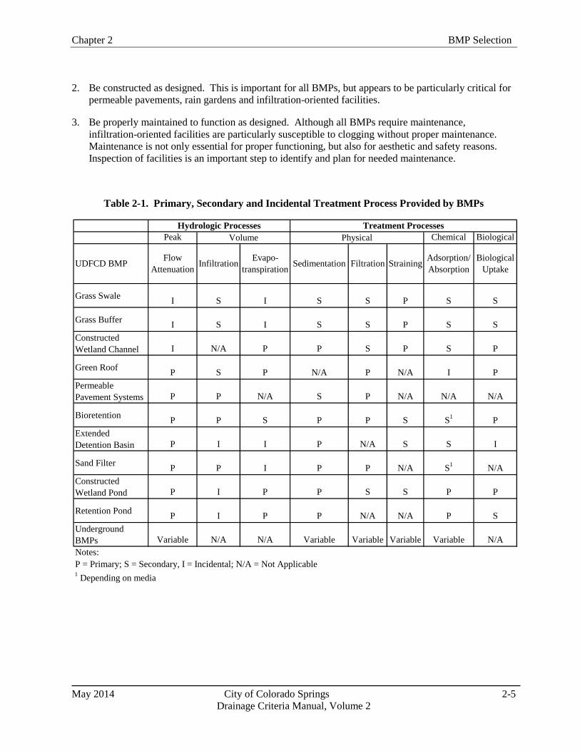
Chapter 2 BMP Selection
May 2014 City of Colorado Springs 2-5
Drainage Criteria Manual, Volume 2
2. Be constructed as designed. This is important for all BMPs, but appears to be particularly critical for
permeable pavements, rain gardens and infiltration-oriented facilities.
3. Be properly maintained to function as designed. Although all BMPs require maintenance,
infiltration-oriented facilities are particularly susceptible to clogging without proper maintenance.
Maintenance is not only essential for proper functioning, but also for aesthetic and safety reasons.
Inspection of facilities is an important step to identify and plan for needed maintenance.
Table 2-1. Primary, Secondary and Incidental Treatment Process Provided by BMPs
Peak Chemical Biological
Grass SwaleI S I S S P S S
Grass BufferI S I S S P S S
Constructed
Wetland Channel I N/A P P S P S P
Green RoofP S P N/A P N/A I P
Permeable
Pavement Systems P P N/A S P N/A N/A N/A
BioretentionP P S P P S S
1P
Extended
Detention Basin P I I P N/A S S I
Sand FilterP P I P P N/A S
1N/A
Constructed
Wetland Pond P I P P S S P P
Retention PondP I P P N/A N/A P S
Underground
BMPs Variable N/A N/A Variable Variable Variable Variable N/A
Notes:
P = Primary; S = Secondary, I = Incidental; N/A = Not Applicable1 Depending on media
Hydrologic Processes Treatment Processes
Volume Physical
UDFCD BMPAdsorption/
Absorption
Biological
Uptake
Flow
AttenuationStrainingFiltrationSedimentation
Evapo-
transpirationInfiltration

BMP Selection Chapter 2
May 2014 City of Colorado Springs 2-6
Drainage Criteria Manual, Volume 2
BM
P C
ateg
ory
Sam
ple
Typ
e
To
tal
Su
spen
ded
So
lid
s
To
tal
Dis
solv
ed
So
lid
s
Nit
rogen
,
To
tal
To
tal
Kje
ldah
l
Nit
rogen
(T
KN
)
Nit
rogen
,
Am
mo
nia
as
N
Nit
rogen
, N
itra
te
(NO
3)
as N
*
Nit
rogen
, N
itri
te
(NO
2)
+ N
itra
te
(NO
3)
as N
*
Ph
osp
ho
rus
as
P,
To
tal
Ph
osp
ho
rus,
Ort
ho
ph
osp
hat
e as
P
44
.6N
C1
.46
1.2
20
.19
NC
0.3
00
.13
0.0
4(4
1.8
-53
.3,
n=
6)
(1.2
4-1
.63
, n
= 7
)(1
.00
-1.3
3,
n=
8)
(0.1
6-0
.23
, n
= 8
)(0
.25
-0.3
8,
n=
10
)(0
.12
-0.1
7,
n=
12
)(0
.01
-0.1
0,
n=
7)
12
.9N
C1
.15
0.9
40
.06
NC
0.2
10
.13
0.0
6(6
.8-1
7.3
, n
= 6
)(0
.92
-2.9
8,
n=
7)
(0.6
0-2
.09
, n
= 8
)(0
.05
-0.3
8,
n=
8)
(0.1
4-0
.29
, n
= 1
0)
(0.0
8-0
.19
, n
= 1
2)
(0.0
3-0
.33
, n
= 7
)
52
.35
7.5
NC
1.4
00
.38
0.4
4N
C0
.18
0.0
4(5
0.0
-63
.3,
n=
14
)(3
2.0
-89
.3,
n=
12
)(1
.15
-2.1
0,
n=
13
)(0
.23
-0.6
4,
n=
10
)(0
.42
-0.9
2,
n=
13
)(0
.09
-0.2
5,
n=
14
)(0
.03
-0.0
6,
n=
10
)
22
.38
8.0
NC
1.2
00
.25
0.3
3N
C0
.30
0.1
0(1
5.0
-28
.3,
n=
14
)(7
3.3
-11
0.0
, n
= 1
2)
(0.9
5-1
.50
, n
= 1
3)
(0.1
3-0
.36
, n
= 9
)(0
.23
-0.7
8,
n=
13
)(0
.11
-0.5
6,
n=
14
)(0
.05
-0.2
9,
n=
10
)
54
.57
9.5
NC
1.8
30
.06
0.4
10
.25
0.2
20
.04
(30
.5-7
6.5
, n
= 1
5)
(64
.2-1
00
.1,
n=
12
)(1
.40
-2.1
1,
n=
12
)(0
.02
-0.0
9,
n=
4)
(0.2
3-0
.78
, n
= 1
2)
(0.1
9-0
.37
, n
= 4
)(0
.13
-0.2
9,
n=
15
)(0
.03
-0.0
4,
n=
3)
18
.07
1.0
0.6
01
.23
0.0
50
.29
0.2
20
.23
0.1
0
(8.9
-39
.5,
n=
19
)(3
4.9
-85
.0,
n=
10
)(0
.55
-1.3
4,
n=
6)
(0.4
1-1
.48
, n
= 1
6)
(0.0
3-0
.06
, n
= 8
)(0
.21
-0.6
6,
n=
15
)(0
.18
-0.3
1,
n=
8)
(0.1
9-0
.31
, n
= 1
9)
(0.0
8-0
.12
, n
= 7
)
59
.58
8.5
1.0
51
.32
0.0
80
.45
0.2
30
.20
NC
(17
.8-8
3.8
, n
= 1
8)
(85
.0-9
8.8
, n
= 6
)(1
.04
-1.2
5,
n=
3)
(0.7
7-1
.70
, n
= 1
0)
(0.0
4-0
.10
, n
= 5
)(0
.30
-0.9
0,
n=
8)
(0.1
7-0
.50
, n
= 5
)(0
.18
-0.3
0,
n=
17
)
22
.08
5.0
2.5
41
.66
0.0
90
.40
0.1
70
.20
NC
(11
.6-2
8.5
, n
= 2
0)
(54
.3-1
13
.5,
n=
6)
(1.7
-2.6
9,
n=
3)
(0.8
6-1
.95
, n
= 1
0)
(0.0
7-0
.10
, n
= 5
)(0
.27
-0.8
5,
n=
8)
(0.0
8-0
.43
, n
= 6
)(0
.13
-0.2
6,
n=
18
)
44
.04
2.0
1.5
11
.53
0.3
40
.38
0.3
30
.20
0.0
2(3
2.0
-75
.0,
n=
21
)(2
8.4
-59
.0,
n=
13
)(0
.73
-1.8
0,
n=
5)
(0.8
7-2
.00
, n
= 1
7)
(0.0
8-1
.12
, n
= 1
1)
(0.2
3-0
.57
, n
= 1
6)
(0.2
3-0
.51
, n
= 6
)(0
.13
-0.3
3,
n=
21
)(0
.02
-0.0
6,
n=
7)
8.0
55
.00
.63
0.8
00
.11
0.6
60
.43
0.1
10
.02
(5.0
-17
.0,
n=
21
)(4
6.0
-62
.0,
n=
13
)(0
.43
-1.4
1,
n=
4)
(0.5
0-1
.22
, n
= 1
7)
(0.0
4-0
.15
, n
= 1
0)
(0.3
9-0
.73
, n
= 1
6)
(0.0
5-1
.00
, n
= 5
)(0
.06
-0.1
5,
n=
21
)(0
.02
-0.0
6,
n=
7)
44
.58
9.0
1.7
11
.18
0.0
90
.43
0.2
70
.23
0.0
9(2
4.0
-88
.3,
n=
40
)(5
9.3
-12
7.5
, n
= 9
)(1
.07
-2.3
6,
n=
19
)(0
.77
-1.4
2,
n=
28
)(0
.04
-0.1
5,
n=
23
)(0
.32
-0.6
9,
n=
15
)(0
.11
-0.5
5,
n=
24
)(0
.14
-0.3
9,
n=
38
)(0
.07
-0.2
1,
n=
26
)
12
.11
51
.31
.31
0.9
90
.07
0.1
90
.05
0.1
10
.05
(7.9
-19
.7,
n=
40
)(7
0.8
-18
2.0
, n
= 9
)(1
.01
-1.5
4,
n=
19
)(0
.76
-1.2
9,
n=
30
)(0
.04
-0.1
7,
n=
24
)(0
.13
-0.2
6,
n=
15
)(0
.02
-0.2
0,
n=
24
)(0
.07
-0.1
9,
n=
40
)(0
.02
-0.0
8,
n=
27
)
39
.6N
A1
.54
1.1
00
.10
0.3
20
.46
0.1
20
.04
(24
.0-5
6.8
, n
= 1
4)
(1.0
7-2
.16
, n
= 6
)(0
.77
-1.3
0,
n=
4)
(0.0
4-0
.13
, n
= 8
)(0
.32
-0.4
4,
n=
5)
(0.1
1-0
.63
, n
= 7
)(0
.14
-0.2
7,
n=
11
)(0
.07
-0.1
3,
n=
5)
12
.0N
C1
.16
1.0
00
.06
0.1
20
.17
0.0
80
.06
(8.5
-17
.5,
n=
16
)(0
.98
-1.3
9,
n=
6)
(0.9
0-1
.14
, n
= 8
)(0
.04
-0.1
0,
n=
8)
(0.1
0-0
.16
, n
= 7
)(0
.05
-0.3
4,
n=
7)
(0.0
5-0
.14
, n
= 1
3)
(0.0
2-0
.25
, n
= 7
)
23
.5N
AN
C2
.40
NC
NC
0.5
90
.12
NC
(16
.0-4
5.3
, n
= 5
)(1
.80
-3.3
0,
n =
3)
(0.2
7-0
.80
, n
= 5
)(0
.10
-0.1
3,
n =
5)
29
.1N
AN
C1
.05
NC
NC
1.2
40
.13
NC
(16
.3-3
4.0
, n
= 7
)(0
.90
-1.3
3,
n =
7)
(1.2
1-1
.39
, n
= 4
)(0
.10
-0.1
9,
n =
5)
*S
om
e B
MP
stu
die
s in
clud
e an
alyse
s fo
r b
oth
NO
2/N
O3
and
NO
3;
ther
efo
re,
thes
e an
alyte
s ar
e re
po
rted
sep
arat
ely,
even
tho
ugh r
esult
s ar
e ex
pec
ted
to
be
com
par
able
in s
torm
wat
er r
uno
ff.
So
lid
s a
nd
Nu
trie
nts
(m
illi
gra
ms/
lite
r)
Bio
rete
nti
on
(w/U
nd
erd
rain
)
Infl
ow
Ou
tflo
w
Gra
ss B
uff
er
Infl
ow
Ou
tflo
w
Gra
ss S
wal
e
Infl
ow
Ou
tflo
w
Det
enti
on
Bas
in
(ab
oveg
rou
nd
exte
nd
ed d
et.)
Infl
ow
Ou
tflo
w
Med
ia F
ilte
rs
(var
iou
s ty
pes
)
Infl
ow
Ou
tflo
w
Per
mea
ble
Pav
emen
t**
Infl
ow
Ou
tflo
w
Ta
ble
No
tes
pro
vid
ed b
elo
w p
art
2 o
f th
is t
ab
le.
Ret
enti
on
Po
nd
(ab
oveg
rou
nd
wet
po
nd
)
Infl
ow
Ou
tflo
w
Wet
lan
d B
asin
Infl
ow
Ou
tflo
w
Ta
ble
2-2
. B
MP
Eff
luen
t E
MC
s (S
ou
rce:
In
tern
ati
on
al
Sto
rmw
ate
r B
MP
Da
tab
ase
,Au
gu
st 2
01
0)

Chapter 2 BMP Selection
May 2014 City of Colorado Springs 2-7
Drainage Criteria Manual, Volume 2
BM
P C
ateg
ory
Sam
ple
Typ
e
Ars
enic
,
Dis
s.
Ars
enic
,
To
tal
Cad
miu
m,
Dis
s.
Cad
miu
m,
To
tal
Ch
rom
ium
,
Dis
s.
Ch
rom
ium
,
To
tal
Co
pp
er,
Dis
s.
Co
pp
er,
To
tal
Lea
d,
Dis
s.
Lea
d,
To
tal
Nic
kel
,
Dis
s.
Nic
kel
,
To
tal
Zin
c,
Dis
s.
Zin
c,
To
tal
NA
NC
NC
NC
NC
NC
NC
19
.5N
CN
CN
CN
CN
C6
8.0
(15
.3-3
5.8
, n
= 3
)(5
1-6
8.5
, n
= 5
)
NA
NC
NC
NC
NC
NC
NC
10
.0N
CN
CN
CN
CN
C8
.5(7
.3-1
6.8
, n
= 3
)(5
.0-3
5.0
, n
= 5
)
0.8
1.1
0.2
0.4
2.4
4.9
12
.92
1.2
0.9
11
.02
.94
.83
7.8
10
0.5
(0.5
-1.2
, n
= 1
2)
(0.9
-2.3
, n
= 1
2)
(0.1
-0.2
, n
= 1
2)
(0.3
-0.8
, n
= 1
2)
(1.1
-4.5
, n
= 1
2)
(2.9
-7.4
, n
= 1
3)
(6.8
-17
.3,
n=
12
)(1
5.0
-41
.0,
n=
13
)(0
.5-2
.0,
n=
12
)(6
-35
, n
= 1
3)
(1.1
-3.2
, n
= 1
2)
(3.4
-8.4
, n
= 1
2)
(12
.8-7
0,
n=
12
)(5
3.0
-24
5.0
, n
= 1
3)
1.2
2.0
0.1
0.2
2.3
2.9
7.1
8.3
0.5
3.2
2.1
2.6
19
.82
5.5
(0.5
-2.4
, n
= 1
2)
(0.7
-3.0
, n
= 1
2)
(0.1
-0.2
, n
= 1
2)
(0.1
-0.2
, n
= 1
2)
(1.0
-3.8
, n
= 1
2)
(2.0
-5.5
, n
= 1
3)
(4.8
-11
.6,
n=
12
)(6
.4-1
2.5
, n
= 1
3)
(0.5
-1.3
, n
= 1
2)
(1.8
-6.0
, n
= 1
3)
(2.0
-2.3
, n
= 1
2)
(2.2
-3.2
, n
= 1
2)
(10
.7-2
4.3
, n
= 1
2)
(15
.0-5
7.9
, n
= 1
3)
0.6
1.7
0.3
0.5
2.2
6.1
10
.63
3.0
1.4
21
.65
.18
.74
0.3
14
9.5
(0.5
-2.2
, n
= 9
)(1
.6-2
.7,
n=
9)
(0.1
-0.4
, n
= 1
3)
(0.4
-0.9
, n
= 1
4)
(1.1
-3.3
, n
= 7
)(3
.6-8
.3,
n=
7)
(8.1
-15
.0,
n=
13
)(2
6-3
4,
n=
13
)(0
.6-6
.7,
n=
13
)(1
2.5
-46
.4,
n=
14
)(4
.5-6
.6,
n=
6)
(7-1
2.5
, n
= 6
)(3
5.3
-10
9.0
, n
= 1
3)
(43
.8-2
44
.3,
n=
15
)
0.6
1.2
0.2
0.3
1.1
3.5
8.6
14
.01
.01
0.5
2.0
4.0
22
.65
5.0
(0.6
-1.2
, n
= 8
)(0
.9-1
.7,
n=
8)
(0.1
-0.2
, n
= 1
2)
(0.2
-0.4
, n
= 1
3)
(1.0
-3.0
, n
= 6
)(1
.7-5
.0,
n=
6)
(5.5
-9.7
, n
= 1
3)
(6.7
-18
.5,
n=
17
)(0
.5-4
.1,
n=
13
)(1
.7-1
2.0
, n
= 1
8)
(2.0
-2.3
, n
= 5
)(3
.1-4
.5,
n=
5)
(20
.1-3
3.2
, n
= 1
3)
(20
.6-6
5.4
, n
= 1
9)
1.1
2.1
0.3
0.6
2.6
5.6
5.8
10
.01
.01
0.0
2.9
6.3
16
.41
25
.0
(0.9
-1.2
, n
= 5
)(1
.3-2
.6,
n=
6)
(0.2
-0.4
, n
= 8
)(0
.3-1
.2,
n=
11
)(2
.0-3
.2,
n=
3)
(5.0
-6.5
, n
= 6
)(2
.6-1
1.8
, n
= 8
)(4
.8-3
3.5
, n
= 1
1)
(0.5
-1.4
, n
= 8
)(1
.5-4
1.0
, n
= 1
1)
(1.9
-3.9
, n
= 4
)(5
-9.4
, n
= 5
)(6
.1-5
3.5
, n
= 8
)(2
1.5
-22
5.3
, n
= 1
1)
1.2
1.7
0.3
0.4
1.9
2.9
9.0
11
.01
.09
.53
.14
.31
9.0
48
.5(0
.9-1
.2,
n=
5)
(1.1
-1.9
, n
= 6
)(0
.2-0
.4,
n=
9)
(0.2
-0.6
, n
= 1
2)
(1.7
-3.0
, n
= 4
)(1
.9-3
.8,
n=
6)
(3.0
-13
.0,
n=
9)
(6.2
-20
.1,
n=
12
)(0
.5-1
.3,
n=
9)
(1.3
-18
.6,
n=
12
)(2
.0-3
.2,
n=
5)
(3.2
-5.4
, n
= 6
)(7
.8-5
4.0
, n
= 9
)(1
9.1
-94
.0,
n=
13
)
0.7
1.1
0.2
0.4
1.0
2.1
6.2
13
.51
.19
.02
.03
.94
2.7
86
.0
(0.5
-1.1
, n
= 1
2)
(0.6
-1.6
, n
= 1
2)
(0.2
-0.2
, n
= 1
4)
(0.2
-1.0
, n
= 1
7)
(1.0
-1.0
, n
= 1
3)
(1.4
-4.0
, n
= 1
3)
(5.4
-7.4
, n
= 1
3)
(8.8
-16
.4,
n=
18
)(1
.0-2
.0,
n=
14
)(5
.3-2
2.0
, n
= 1
7)
(2.0
-2.7
, n
= 1
3)
(3.3
-4.8
, n
= 1
3)
(28
.5-7
9.2
, n
= 1
4)
(51
.8-1
06
.0,
n=
19
)
0.7
1.1
0.2
0.2
1.0
1.0
5.8
7.3
1.0
1.6
2.0
2.9
12
.52
0.0
(0.6
-1.1
, n
= 1
2)
(0.7
-1.6
, n
= 1
2)
(0.2
-0.2
, n
= 1
3)
(0.1
-0.7
, n
= 1
7)
(1.0
-1.0
, n
= 1
3)
(1.0
-1.9
, n
= 1
3)
(3.1
-8.3
, n
= 1
3)
(4.3
-9.6
, n
= 1
8)
(1.0
-1.0
, n
= 1
3)
(1.0
-4.4
, n
= 1
7)
(2.0
-2.6
, n
= 1
3)
(2.0
-3.9
, n
= 1
3)
(6.7
-49
.0,
n=
13
)(8
.6-3
5.0
, n
= 1
9)
NC
1.0
0.2
1.0
5.9
5.0
7.0
6.3
2.0
9.7
10
.06
.53
0.0
51
.8
(1.0
-1.4
, n
= 3
)(0
.2-0
.4,
n=
3)
(0.3
-2.6
, n
= 2
0)
(1.6
-10
.0,
n=
4)
(3.0
-7.4
, n
= 1
2)
(6.0
-9.5
, n
= 7
)(4
.3-1
0.6
, n
= 2
6)
(1.0
-5.1
.0,
n=
11
)(4
-28
, n
= 3
3)
(6.2
-10
.0,
n=
3)
(3.6
-9,
n=
8)
(15
.5-4
2.6
, n
= 8
)(4
3.9
-78
.1,
n=
32
)
NC
1.0
0.2
0.4
5.5
2.2
5.0
5.4
1.2
4.7
10
.02
.51
2.5
26
.0(0
.8-1
.0,
n=
3)
(0.2
-0.4
, n
= 3
)(0
.2-2
.5,
n=
20
)(1
.0-1
0.0
, n
= 4
)(1
.4-5
.3,
n=
12
)(4
.7-5
.8,
n=
7)
(3.0
-6.2
, n
= 2
6)
(1.0
-4.9
, n
= 1
2)
(1.6
-10
.0,
n=
33
)(7
.2-1
0.0
, n
= 3
)(2
.0-5
.5,
n=
9)
(9.4
-28
.6,
n=
8)
(12
.0-3
7.0
, n
= 3
3)
NA
NA
NC
0.3
NA
NA
NC
10
.5N
C1
6.0
NA
NA
NC
51
.0
(0.3
-0.4
, n
= 3
)(4
.3-1
5.9
, n
= 4
)(4
.0-2
3.8
, n
= 4
)(4
3.9
-12
0.8
, n
= 7
)
NA
NA
0.5
0.3
NA
NA
5.0
4.5
1.0
1.0
NA
NA
11
.01
5.0
(0.3
-0.5
, n
= 3
)(0
.1-0
.5,
n=
5)
(5.0
-5.7
, n
= 3
)(3
.3-5
.0,
n=
6)
(0.8
-1.0
, n
= 3
)(1
.0-2
.5,
n=
6)
(11
.0-1
3.1
, n
= 3
)(5
.0-2
8.9
, n
= 9
)
NA
NC
NC
NA
NC
NC
5.0
7.0
0.1
2.5
NC
NC
25
.05
0.0
(2.5
-6.4
, n
=3
)(4
.5-1
9.4
, n
= 3
)(0
.03
-0.3
, n
= 3
)(1
.3-1
5.1
, n
= 3
)(1
9.0
-27
.5,
n =
3)
(45
.0-5
1.0
, n
= 5
)
NA
NC
NC
0.3
NC
NC
6.2
9.0
0.3
2.5
NC
NC
14
.62
2.0
(0.3
-0.4
, n
=3
)(4
.5-6
.4,
n =
4)
(3.0
-14
.7,
n =
5)
(0.0
4-0
.5,
n =
4)
(1.3
-9.5
, n
= 7
)(1
3.5
-16
.0,
n =
4)
(20
.0-3
1.6
, n
= 7
)
Ta
ble
Key
Sam
ple
Typ
eA
nal
yte
52
.3
(50
-63
.3,
n=
14
)
22
.3
(15
-28
.3,
n=
14
)=
Inte
rquar
tile
ran
ge,
sam
ple
siz
e
Val
ues
bel
ow
det
ecti
on l
imit
s re
pla
ced
wit
h 1
/2 o
f d
etec
tio
n l
imit
.
= M
edia
n o
utf
low
val
ue
= I
nte
rquar
tile
ran
ge,
sam
ple
siz
e
= M
edia
n i
nfl
ow
val
ue
Des
crip
tio
n
Inte
rquar
tile
Ran
ge
= 2
5th
per
centi
le t
o 7
5th
per
centi
le v
alues
, ca
lcula
ted
in E
xce
l, w
hic
h u
ses
linea
r in
terp
ola
tio
n t
o c
alcu
late
per
centi
les.
F
or
smal
l sa
mp
le s
izes
(p
arti
cula
rly n
<5
),
inte
rquar
tile
val
ues
may
var
y d
epen
din
g o
n s
tati
stic
al p
ackag
e use
d.
NA
= N
ot
avai
lab
le;
stud
ies
conta
inin
g 3
or
mo
re s
torm
s no
t av
aila
ble
.
NC
= N
ot
calc
ula
ted
bec
ause
few
er t
han
3 B
MP
stu
die
s fo
r th
is c
ateg
ory
.
Thes
e d
escr
ipti
ve
stat
isti
cs a
re b
ased
on d
iffe
rent
stat
isti
cal
mea
sure
s th
an t
ho
se u
sed
in t
he
20
08
BM
P D
atab
ase
tab
ula
r su
mm
ary.
Be
awar
e th
at r
esult
s w
ill
var
y d
epen
din
g o
n w
het
her
a "
BM
P W
eighte
d"
(o
ne
med
ian o
r av
erag
e val
ue
rep
rese
nts
eac
h B
MP
) o
r "S
torm
Wei
ghte
d"
(all
sto
rms
for
all
BM
Ps
incl
ud
ed i
n s
tati
stic
al c
alcu
lati
ons)
ap
pro
ach i
s use
d,
as w
ell
as w
het
her
the
med
ian o
r an
oth
er m
easu
re o
f ce
ntr
al t
end
ency
is
use
d.
Sev
eral
BM
P D
atab
ase
pub
lica
tio
ns
in 2
01
0 h
ave
focu
sed
on t
he
sto
rm-w
eighte
d a
pp
roac
h,
whic
h m
ay
resu
lt i
n s
om
e d
iffe
rence
s b
etw
een t
his
tab
le a
nd
oth
er p
ub
lish
ed s
um
mar
ies.
Ou
tflo
w
Det
enti
on
Bas
in
(ab
oveg
rou
nd
exte
nd
ed d
et.)
Infl
ow
Ou
tflo
w
Med
ia F
ilte
rs
(var
iou
s ty
pes
)
Gra
ss B
uff
er
Infl
ow
Ou
tflo
w
Gra
ss S
wal
e
Infl
ow
Ou
tflo
w
Des
crip
tive
stat
isti
cs c
alcu
late
d b
y w
eighti
ng e
ach B
MP
stu
dy e
qual
ly.
Eac
h B
MP
stu
dy i
s re
pre
sente
d b
y t
he
med
ian a
nal
yte
val
ue
rep
ort
ed f
or
all
sto
rms
mo
nit
ore
d a
t ea
ch B
MP
(i.
e.,
"n"
= n
um
ber
of
BM
P s
tud
ies,
as
op
po
sed
to
num
ber
of
sto
rm e
ven
ts).
Dep
end
ing o
n t
he
anal
ysi
s o
bje
ctiv
es,
rese
arch
ers
may
als
o c
ho
ose
to
use
a s
torm
-wei
ghte
d a
nal
ysi
s ap
pro
ach,
a unit
tre
atm
ent
pro
cess
-bas
ed g
roup
ing o
f st
ud
ies,
or
oth
er s
cree
nin
g b
ased
on d
esig
n p
aram
eter
s an
d s
ite-
spec
ific
char
acte
rist
ics.
Anal
ysi
s b
ased
on A
ugust
20
10
BM
P D
atab
ase,
whic
h c
onta
ins
sub
stan
tial
chan
ges
rel
ativ
e to
the
20
08
BM
P D
atab
ase.
M
ult
iple
BM
Ps
hav
e b
een r
ecat
ego
rize
d i
nto
new
BM
P c
ateg
ori
es;
ther
efo
re,
the
20
08
and
20
10
dat
a an
alysi
s ar
e no
t d
irec
tly c
om
par
able
fo
r se
ver
al
BM
P t
yp
es.
This
tab
le c
onta
ins
des
crip
tive
stat
isti
cs o
nly
. V
alues
pre
sente
d i
n t
his
tab
le s
ho
uld
no
t b
e use
d t
o d
raw
co
ncl
usi
ons
rela
ted
to
sta
tist
ical
ly s
ignif
ican
t d
iffe
rence
s in
per
form
ance
fo
r B
MP
cat
ego
ries
. (H
yp
oth
esis
tes
ting f
or
BM
P C
ateg
ori
es i
s p
rovid
ed s
epar
atel
y i
n o
ther
BM
P D
atab
ase
sum
mar
ies
avai
lab
le a
t w
ww
.bm
pd
atab
ase.
org
.)
Outf
low
**P
erm
eab
le p
avem
ent
dat
a sh
ould
be
use
d w
ith c
auti
on d
ue
to l
imit
ed n
um
ber
s o
f B
MP
stu
die
s an
d s
mal
l num
ber
s o
f st
orm
even
ts t
yp
ical
ly m
onit
ore
d a
t th
ese
site
s.
"Infl
ow
" val
ues
are
typ
ical
ly o
utf
low
s m
onit
ore
d a
t a
refe
rence
co
nven
tio
nal
pav
ing s
ite.
Ta
ble
No
tes:
Per
mea
ble
Pav
emen
t**
Infl
ow
Ou
tflo
w
Infl
ow
Ret
enti
on
Po
nd
(ab
oveg
rou
nd
wet
po
nd
)
Infl
ow
Ou
tflo
w
Wet
lan
d B
asin
Infl
ow
Infl
ow
Ou
tflo
w
Meta
ls (
mic
ro
gra
ms/
lite
r)
Bio
rete
nti
on
(w/U
nd
erd
rain
)
Infl
ow
Ou
tflo
w

BMP Selection Chapter 2
May 2014 City of Colorado Springs 2-8
Drainage Criteria Manual, Volume 2
Hydromodification
The term hydro-modification refers to altered
hydrology due to increased imperviousness
combined with constructed of conveyance
systems (e.g., pipes) that convey stormwater
efficiently to receiving waters.
Hydromodification produces increased peaks,
volume, frequency, and duration of flows, all of
which can result in stream degradation,
including stream bed down cutting, bank
erosion, enlarged channels, and disconnection
of streams from the floodplain. These factors
lead to loss of stream and riparian habitat,
reduced aquatic diversity, and can adversely
impact the beneficial uses of our waterways.
1.4 Storage-Based Versus Conveyance-Based
BMPs in this manual generally fall into two categories: 1) storage-based and 2) conveyance-based.
Storage-based BMPs provide the WQCV and include bioretention/rain gardens, extended detention
basins, sand filters, constructed wetland ponds, retention ponds, and permeable pavement systems.
Conveyance-based BMPs include grass swales, grass buffers, constructed wetlands channels and other
BMPs that improve quality and reduce runoff but only provide incidental storage. Conveyance-based
BMPs can be implemented to help achieve objectives in Step 1 of the Four Step Process. Although
conveyance BMPs do not satisfy Step 2 (providing the WQCV), they can reduce the volume requirements
of Step 2. Storage-based BMPs are critical for Step 2 of the Four Step Process. Site plans that use a
combination of conveyance-based and storage-based BMPs can be used to better mimic pre-development
hydrology.
1.5 Runoff Reduction
BMPs that promote infiltration or that incorporate
evapotranspiration have the potential to reduce the
runoff generated. Runoff reduction is a fundamental
objective of LID. Runoff reduction has many
benefits, both in terms of hydrology and pollution
control. While stormwater regulations have
traditionally focused on runoff peak flow rates,
emerging stormwater regulations require BMPs to
mimic the pre-development hydrologic budget to
minimize effects of hydro-modification. From a
pollution perspective, decreased runoff volume
translates to decreased pollutant loads. Runoff
reduction can have economic benefits, including
potential reductions in storage requirements for minor
and major events, reduced extent and sizing of
conveyance infrastructure, and cost reductions
associated with addressing channel stability issues. A
computational method for quantifying runoff
reduction is discussed in detail in Chapter 3.
Infiltration-based BMPs can be designed with or without underdrains, depending on soil permeability and
other site conditions. The most substantial runoff reductions are generally associated with BMPs that
have permeable sub-soils and allow infiltration to deeper soil strata and eventually groundwater. For
BMPs that have underdrains, there is still potential for runoff reduction although to a lesser degree. As
runoff infiltrates through BMP soils to the underdrain, moisture is retained by soils. The moisture
eventually evaporates, or is taken up by vegetation, resulting in runoff reduction. Runoff that drains from
these soils via gravity to the underdrain system behaves like interflow from a hydrologic perspective with
a delayed response that reduces peak rates. Although the runoff collected in the underdrain system is
ultimately discharged to the surface, on the time scale of a storm event, there are runoff reduction
benefits.
Although effects of evapotranspiration are inconsequential on the time scale of a storm event, on an
annual basis, runoff reduction due to evapotranspiration for vegetated BMPs such as retention and
constructed wetland ponds can be an important component of the hydrologic budget. Between events,
evapotranspiration lowers soil moisture content and permanent pool storage, providing additional storage
Chapter 2 BMP Selection
May 2014 City of Colorado Springs 2-9
Drainage Criteria Manual, Volume 2
capacity for subsequent events.
Other surface BMPs also provide runoff reduction through a combination of infiltration, use by the
vegetation and evaporation. Runoff reduction provided by a particular BMP type will be influenced by
site-specific conditions and BMP design features. National research is ongoing with regard to estimating
runoff reduction provided by various BMP types. Based on analysis of BMP studies contained in the
International Stormwater BMP Database, Geosyntec and WWE (2010) reported that normally-dry
vegetated BMPs (filter strips, vegetated swales, bioretention, and grass lined detention basins) appear to
have substantial potential for runoff volume reduction on a long-term basis, on the order of 30 percent for
filter strips and grass-lined detention basins, 40 percent for grass swales, and greater than 50 percent for
bioretention with underdrains. Bioretention facilities without underdrains would be expected to provide
greater runoff volume reduction.
1.6 Pretreatment
Forebays, as described and designed in the USDCM, are required for extended detention basins,
constructed wetland basins, and retention ponds unless a variance request is submitted and approved. The
purpose of forebays is to settle out coarse sediment prior to reaching the main body of the facility. During
construction, source control including good housekeeping can be more effective than pre-treatment. It is
extremely important that high sediment loading be controlled for BMPs that rely on infiltration, including
permeable pavement systems, rain gardens, and sand filter extended detention basins. These facilities
should not be brought on-line until the end of the construction phase when the tributary drainage area has
been stabilized with permanent surfaces and landscaping.
1.7 Treatment Train
The term "treatment train" refers to multiple BMPs in series (e.g., a disconnected roof downspout
draining to a grass swale draining to a constructed wetland basin.) Engineering research over the past
decade has demonstrated that treatment trains are one of the most effective methods for management of
stormwater quality (WERF 2004). Advantages of treatment trains include:
Multiple processes for pollutant removal: There is no "silver bullet" for a BMP that will address
all pollutants of concern as a stand-alone practice. Treatment trains that link together complementary
processes expand the range of pollutants that can be treated with a water quality system and increase
the overall efficiency of the system for pollutant removal.
Redundancy: Given the natural variability of the volume, rate and quality of stormwater runoff and
the variability in BMP performance, using multiple practices in a treatment train can provide more
consistent treatment of runoff than a single practice and provide redundancy in the event that one
component of a treatment train is not functioning as intended.
Maintenance: BMPs that remove trash, debris, coarse sediments and other gross solids are a
common first stage of a treatment train. From a maintenance perspective, this is advantageous since
this first stage creates a well-defined, relatively small area that can be cleaned out routinely. Down-
gradient components of the treatment train can be maintained less frequently and will benefit from
reduced potential for clogging and accumulation of trash and debris.
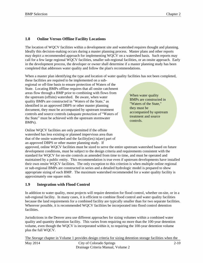
BMP Selection Chapter 2
May 2014 City of Colorado Springs 2-10
Drainage Criteria Manual, Volume 2
When water quality
BMPs are constructed in
"Waters of the State,"
they must be
accompanied by upstream
treatment and source
controls.
1.8 Online Versus Offline Facility Locations
The location of WQCV facilities within a development site and watershed requires thought and planning.
Ideally this decision-making occurs during a master planning process. Master plans and other reports
may depict a recommended approach for implementing WQCV on a watershed basis. Such reports may
call for a few large regional WQCV facilities, smaller sub-regional facilities, or an onsite approach. Early
in the development process, the developer or owner shall determine if a master planning study has been
completed that addresses water quality and follow the plan's recommendations.
When a master plan identifying the type and location of water quality facilities has not been completed,
these facilities are required to be implemented on a sub-
regional or off-line basis to ensure protection of Waters of the
State. Locating BMPs offline requires that all onsite catchment
areas flow through a BMP prior to combining with flows from
the upstream (offsite) watershed. Be aware, when water
quality BMPs are constructed in "Waters of the State," as
identified in an approved DBPS or other master planning
document, they must be accompanied by upstream treatment
controls and source controls (adequate protection of “Waters of
the State” must be achieved with the upstream stormwater
BMPs).
Online WQCV facilities are only permitted if the offsite
watershed has less existing or planned impervious area than
that of the onsite watershed and the facility(ies) is(are) part of
an approved DBPS or other master planning study. If
approved, online WQCV facilities must be sized to serve the entire upstream watershed based on future
development conditions, must be subject to the design criteria and requirements consistent with the
standard for WQCV for on-site controls as amended from time to time, and must be operated and
maintained by a public entity. This recommendation is true even if upstream developments have installed
their own onsite WQCV facilities. The only exception to this criterion is when multiple online regional
or sub-regional BMPs are constructed in series and a detailed hydrologic model is prepared to show
appropriate sizing of each BMP. The maximum watershed recommended for a water quality facility is
approximately one square mile.
1.9 Integration with Flood Control
In addition to water quality, most projects will require detention for flood control, whether on-site, or in a
sub-regional facility. In many cases, it is efficient to combine flood control and water quality facilities
because the land requirements for a combined facility are typically smaller than for two separate facilities.
Wherever possible, it is recommended WQCV facilities be incorporated into flood control detention
facilities.
Jurisdictions in the Denver area use different approaches for sizing volumes within a combined water
quality and quantity detention facility. This varies from requiring no more than the 100-year detention
volume, even though the WQCV is incorporated within it, to requiring the 100-year detention volume
plus the full WQCV.
The Storage chapter in Volume 1 provides design criteria for sizing detention storage facilities when the
Chapter 2 BMP Selection
May 2014 City of Colorado Springs 2-11
Drainage Criteria Manual, Volume 2
WQCV is integrated with flood control storage. Full spectrum detention shows more promise in
controlling the peak flow rates in receiving waterways than the multi-stage designs described above. Full
spectrum detention not only addresses the WQCV for controlling water quality and runoff from
frequently occurring runoff events, but also extends that control for all return periods through the 100-
year event and more closely matches historic peak flows downstream and helps to mitigate increases in
runoff volume by releasing the excess volume over many hours.
Finally, designers should also be aware that water quality BMPs, especially those that promote
infiltration, could result in volume reductions for flood storage. These volume reductions are most
pronounced for frequently occurring events, but even in the major event, some reduction in detention
storage volume can be achieved if volume-reduction BMPs are widely used on a site. Additional
discussion on runoff reduction benefits, including a methodology for quantifying effects on detention
storage volumes, is provided in Chapter 3.
1.9.1 Sedimentation BMPs
Combination outlets are relatively straightforward for most BMPs in this manual. For BMPs that utilize
sedimentation (e.g. EDBs, constructed wetland ponds, and retention ponds) see BMP Fact Sheet T-12.
This Fact Sheet shows examples and details for combined quality/quantity outlet structures.
1.9.2 Infiltration/Filtration BMPs
For other types of BMPs (e.g. rain gardens, sand filters, permeable pavement systems, and other BMPs
utilizing processes other than sedimentation), design of a combination outlet structure generally consists
of multiple orifices to provide controlled release of WQCV as well as the minor and major storm event.
Incorporation of full spectrum detention into these structures requires reservoir routing. The UD-
Detention worksheet available at UDFCD website can be used for this design. When incorporating flood
control into permeable pavement systems, the design can be simplified when a near 0% slope on the
pavement surface can be achieved. The flatter the pavement the fewer structures required. This includes
lateral barriers as well as outlet controls since each pavement cell typically requires its own outlet
structure. When incorporating flood control into a rain garden, the flood control volume can be placed on
top of or downstream of the rain garden. Locating the flood control volume downstream can reduce the
total depth of the rain garden, which will result in a more attractive BMP, and also benefit the vegetation
in the flood control area because inundation and associated sedimentation will be less frequent, limited to
events exceeding the WQCV.
1.10 Land Use, Compatibility with Surroundings, and Safety
Stormwater quality areas can add interest and diversity to a site, serving multiple purposes in addition to
providing water quality functions. Gardens, plazas, rooftops, and even parking lots can become amenities
and provide visual interest while performing stormwater quality functions and reinforcing urban design
goals for the neighborhood and community. The integration of BMPs and associated landforms, walls,
landscape, and materials can reflect the standards and patterns of a neighborhood and help to create lively,
safe, and pedestrian-oriented districts. The quality and appearance of stormwater quality facilities should
reflect the surrounding land use type, the immediate context, and the proximity of the site to important
civic spaces. Aesthetics will be a more critical factor in highly visible urban commercial and office areas
than at a heavy industrial site. The standard of design and construction should maintain and enhance
property values without compromising function (WWE et al. 2004).
Public access to BMPs shall be considered from a safety perspective. The highest priority of engineers

BMP Selection Chapter 2
May 2014 City of Colorado Springs 2-12
Drainage Criteria Manual, Volume 2
and public officials is to protect public health, safety, and welfare. Stormwater quality facilities must be
designed and maintained in a manner that does not pose health or safety hazards to the public. As an
example, steeply sloped and/or walled ponds should be avoided. Where this is not possible, emergency
egress, lighting and other safety considerations shall be incorporated. Facilities shall be designed to
reduce the likelihood and extent of shallow standing water that can result in mosquito breeding, which
can be a nuisance and a public health concern (e.g., West Nile virus). The potential for nuisances, odors
and prolonged soggy conditions shall be evaluated for BMPs, especially in areas with high pedestrian
traffic or visibility.
1.11 Maintenance and Sustainability
Maintenance shall be considered early in the planning and design phase. Even when BMPs are
thoughtfully designed and properly installed, they can become eyesores, breed mosquitoes, and cease to
function if not properly maintained. BMPs can be more effectively maintained when they are designed to
allow easy access for inspection and maintenance and to take into consideration factors such as property
ownership, easements, visibility from easily accessible points, slope, vehicle access, and other factors.
For example, fully consider how and with what equipment BMPs will be maintained in the future. Clear,
legally-binding written agreements assigning maintenance responsibilities and committing adequate funds
for maintenance are also critical (WWE et al. 2004). This is discussed in greater detail in Chapter 6. The
right of access to perform emergency repairs/maintenance is required on privately owned and maintained
BMPs should it become necessary.
Sustainability of BMPs is based on a variety of considerations related to how the BMP will perform over
time. For example, vegetation choices for BMPs determine the extent of supplemental irrigation required.
Choosing native or drought-tolerant plants and seed mixes (as recommended in the Revegetation chapter
of Volume 1) helps to minimize irrigation requirements following plant establishment. Other
sustainability considerations include watershed conditions. For example, in watersheds with ongoing
development, clogging of infiltration BMPs is a concern. In such cases, a decision must be made
regarding either how to protect and maintain infiltration BMPs, or whether to allow use of infiltration
practices under these conditions.
1.12 Costs
Costs are a fundamental consideration for BMP selection, but often the evaluation of costs during
planning and design phases of a project focuses narrowly on up-front, capital costs. A more holistic
evaluation of life-cycle costs including operation, maintenance and rehabilitation is prudent and is
discussed in greater detail in Section 4 of this chapter. From a municipal perspective, cost considerations
are even broader, involving costs associated with off-site infrastructure, channel stabilization and/or
rehabilitation, and protection of community resources from effects of runoff from urban areas.
2.0 BMP Selection Tool
To aid in selection of BMPs the use of UDFCD’s BMP selection tool (UD-BMP) is recommended. UD-
BMP guides users of this manual through many of the considerations identified above and determines
what types of BMPs are most appropriate for a site. This tool helps to screen BMPs at the planning stages
of development and can be used in conjunction with the BMP-REALCOST tool described in Section 4.
Simplified schematics of the factors considered in the UD-BMP tool are provided in Figures 2-1, 2-2, and
2-3, which correspond to highly urbanized settings, conventional developments, and linear construction in
urbanized areas. Separate figures are provided because each setting or type of development presents
unique constraints. Highly urbanized sites are often lot-line to lot-line developments or redevelopments

Chapter 2 BMP Selection
May 2014 City of Colorado Springs 2-13
Drainage Criteria Manual, Volume 2
with greater than 90 percent imperviousness with little room for BMPs. Linear construction typically
refers to road and rail construction.
Figure 2-1. BMP Decision Tree for Highly Urbanized Sites
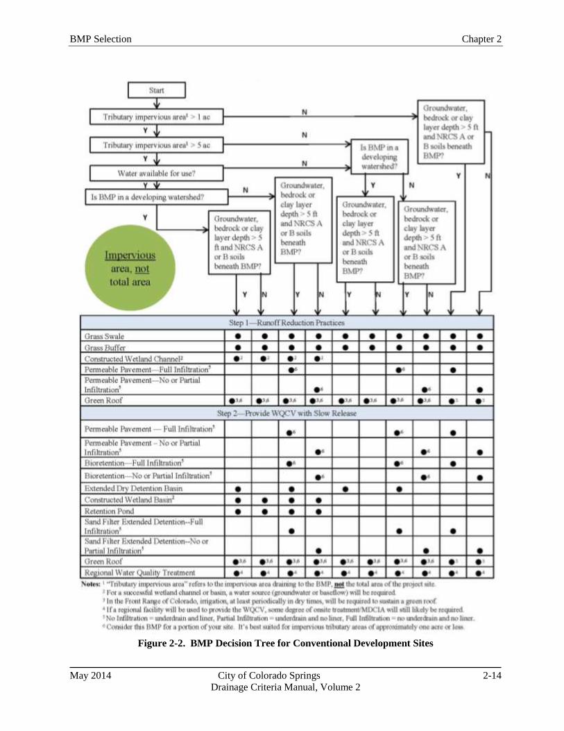
BMP Selection Chapter 2
May 2014 City of Colorado Springs 2-14
Drainage Criteria Manual, Volume 2
Figure 2-2. BMP Decision Tree for Conventional Development Sites

Chapter 2 BMP Selection
May 2014 City of Colorado Springs 2-15
Drainage Criteria Manual, Volume 2
Figure 2-3. BMP Decision Tree for Linear Construction in Urbanized Areas
BMP Selection Chapter 2
May 2014 City of Colorado Springs 2-16
Drainage Criteria Manual, Volume 2
3.0 Life Cycle Cost and BMP Performance Tool
The importance of cost effective BMP planning and selection is gaining recognition as agencies
responsible for stormwater management programs continue to face stricter regulations and leaner budgets.
The goal of the BMP-REALCOST tool is to help select BMPs that meet the project objectives at the
lowest unit cost, where the project objectives are quantifiable measures such as reducing pollutant loads
or runoff to a receiving water. To do so, UDFCD developed an approach that provides estimates for both
the whole life costs and performance of BMPs. The approach was developed to be most effective at the
large-scale, planning phase. However, it can also be applied to smaller scale projects during the design
phase, with only minor loss of accuracy. The BMP-REALCOST spreadsheet tool incorporates this
approach and requires minimal user inputs in order to enhance its applicability to planning level
evaluations. An overview of the general concepts providing the underlying basis of the tool follows.
3.1 BMP Whole Life Costs
Whole life costs (also known as life cycle costs) refer to all costs that occur during the economic life of a
project. This method of cost estimating has gained popularity in the construction and engineering fields
over the past few decades and the American Society of Civil Engineers (ASCE) encourages its use for all
civil engineering projects. Generally, the components of the whole life cost for a constructed facility
include construction, engineering and permitting, contingency, land acquisition, routine operation and
maintenance, and major rehabilitation costs minus salvage value. It is recommended that the cost of
administering a stormwater management program also be included as a long-term cost for BMPs.
Reporting whole life costs in terms of net present value (NPV) is an effective method for comparing
mutually exclusive alternatives (Newnan 1996).
To understand the value of using whole life cost estimating, one must first realize how the various costs
of projects are generally divided amongst several stakeholders. For example, a developer is typically
responsible for paying for the "up front" costs of construction, design, and land acquisition; while a
homeowners' association or owner becomes responsible for all costs that occur after construction. Many
times, the ratios of these costs are skewed one way or another, with BMPs that are less expensive to
design and construct having greater long-term costs, and vice versa. This promotes a bias, depending on
who is evaluating the BMP cost effectiveness. Whole life cost estimating removes this bias, but
successful implementation of the concept requires a cost-sharing approach where the whole life costs are
equitably divided amongst all stakeholders.
The methods incorporated into the BMP-REALCOST tool for estimating whole life costs are briefly
described below. All cost estimates are considered "order-of-magnitude" approximations. This concept
must primarily be relied upon at the planning level.
Construction Costs: Construction costs are estimated using a parametric equation that relates costs
to a physical parameter of a BMP; total storage volume (for storage-based BMPs), peak flow capacity
(for flow-based or conveyance BMPs) or surface area (for permeable pavements).
Contingency/Engineering/Administration Costs: The additional costs of designing and permitting
a new BMP are estimated as a percentage of the total construction costs. A value of 40% is
recommended if no other information is available.
Land Costs: The cost of purchasing land for a BMP is estimated using a derived equation that
incorporates the number of impervious acres draining to the BMP and the land use designation in
which the BMP will be constructed.
Chapter 2 BMP Selection
May 2014 City of Colorado Springs 2-17
Drainage Criteria Manual, Volume 2
Maintenance Costs: Maintenance costs are estimated using a derived equation that relates average
annual costs to a physical parameter of the BMP.
Administration Costs: The costs of administering a stormwater management program are estimated
as a percentage of the average annual maintenance costs of a BMP. A value of 12% is recommended
if no other information is available.
Rehabilitation/Replacement Costs: After some period of time in operation, a BMP will require
"major" rehabilitation. The costs of these activities (including any salvage costs or value) are
estimated as a percentage of the original construction costs and applied near the end of the facility's
design life. The percentages and design lives vary according to the selected BMP.
3.2 BMP Performance
The performance of structural BMPs can be measured as the reduction in stormwater pollutant loading,
runoff volume, and runoff peak flows to the receiving water. It is generally acknowledged that estimating
BMP performance on a storm-by-storm basis is unreliable, given the inherent variability of stormwater
hydrologic and pollutant build-up/wash off processes. Even if the methods to predict event-based BMP
performance were available, the data and computing requirements to do so would likely not be feasible at
the planning level. Instead, it is recommended to use an approach that is expected to predict long-term
(i.e. average annual) BMP pollutant removal and runoff volume reduction with reasonable accuracy,
using BMP performance data reported in the International Stormwater BMP Database (as discussed in
Section 1.3).
3.3 Cost Effectiveness
The primary outputs of the BMP-REALCOST tool include net present value (NPV) of the whole life costs
of the BMP(s) implemented, the average annual mass of pollutant removed (PR, lbs/year) and the average
annual volume of surface runoff reduced (RR, ft3/year). These reported values can then be used to
compute a unit cost per lb of pollutant (CP) or cubic feet of runoff (CR) removed over the economic life
(n, years) of the BMP using Equations 2-1 and 2-2, respectively.
Equation 2-1
Equation 2-2
4.0 Conclusion
A variety of factors should be considered when selecting stormwater management approaches for
developments. When these factors are considered early in the design process, significant opportunities
exist to tailor stormwater management approaches to site conditions. Two worksheets are available at the
UDFCD website for the purpose of aiding the owner or engineer in the proper selection of treatment
BMPs. The UD-BMP tool provides a list of BMPs for consideration based on site-specific conditions.
BMP-REALCOST provides a comparison of whole life cycle costs associated with various BMPs based
on land use, watershed size, imperviousness, and other factors.
BMP Selection Chapter 2
May 2014 City of Colorado Springs 2-18
Drainage Criteria Manual, Volume 2
5.0 References
Geosyntec and Wright Water Engineers, 2010. International Stormwater Best Management Practices
(BMP) Database Technical Summary: Volume Reduction. Prepared for the Water Environment
Research Foundation, Federal Highway Administration, and the Environment and Water
Resources Institute of the American Society of Civil Engineers.
Hartigan, J.P. 1989. Basis for Design of Wet Detention Basin BMPs. Design of Urban Runoff Quality
Controls. Proceedings Engineering Foundation Conference. American Society of Civil
Engineers (ASCE): New York, NY.
Metcalf and Eddy, Inc. 2003. Wastewater Engineering, Treatment, Disposal and Reuse. Fourth Edition.
Revised by G. Tchobanoglous and F.L. Burton. McGraw Hill: New York, NY.
Newnan, Donald G. 1996. Engineering Economic Analysis. Sixth Edition. Engineering Press: San
Jose, CA.
Randall, C.W., K. Ellis, T.J. Grizzard, and W.R. Knocke. 1982. Urban Runoff Pollutant Removal by
Sedimentation. Stormwater Detention Facilities. Proceedings of the Engineering Foundation
Conference. ASCE: New York, NY.
Roesner, L. and C. Olson. 2009. BMP-REALCOST.xls Spreadsheet Tool. Prepared for Urban Drainage
and Flood Control District: Denver, CO.
Stahre, P. and B. Urbonas. 1990. Stormwater Detention for Drainage, Water Quality, and CSO
Management. Prentice Hall.
Water Environment Federation (WERF). 2005. Critical Assessment of Stormwater Treatment Controls
and Control Selection Issues. 02-SW-01. WERF: Alexandria, VA: IWA Publishing: London.
Wright Water Engineers, Inc., Wenk Associates, Muller Engineering Company, Inc., Matrix Design
Group, and Smith Environmental. 2004. City and County of Denver Water Quality Management
Plan. Denver, CO
May 2014 City of Colorado Springs 3-i
Drainage Criteria Manual, Volume 2
Chapter 3
Calculating the WQCV and Runoff Reduction
Contents
1.0 Introduction ...................................................................................................................................... 1
2.0 Hydrologic Basis of the WQCV ...................................................................................................... 1 2.1 Development of the WQCV ...................................................................................................................... 1 2.2 Optimizing the Capture Volume ............................................................................................................... 3 2.3 Attenuation of the WQCV (BMP Drain Time) ......................................................................................... 3 2.4 Excess Urban Runoff Volume (EURV) and Full Spectrum Detention ..................................................... 4
3.0 Calculation of the WQCV................................................................................................................ 4
4.0 Quantifying Runoff Reduction ........................................................................................................ 7 4.1 Conceptual Model for Runoff Reduction BMPs—Cascading Planes ....................................................... 7 4.2 Watershed/Master Planning-level Runoff Reduction Method .................................................................. 8 4.3 Site-level Runoff Reduction Methods ....................................................................................................... 9
4.3.1 SWMM Modeling Using Cascading Planes ................................................................................ 10 4.3.2 IRF (K) Charts and Spreadsheet ................................................................................................. 11
5.0 Examples ......................................................................................................................................... 15 5.1 Calculation of WQCV ............................................................................................................................. 15 5.2 Runoff Reduction Calculations for Storage-based Approach ................................................................. 15 5.3 Effective Imperviousness Spreadsheet .................................................................................................... 17
6.0 Conclusion ....................................................................................................................................... 24
7.0 References ....................................................................................................................................... 29
Figures
Figure 3-1. Map of the Average Runoff Producing Storm's Precipitation Depth in the United States ....... 2 Figure 3-2. Water Quality Capture Volume (WQCV) Based on BMP Drain Time .................................... 6
Figure 3-3. Four Component Land Use……………………………………………………………………8
Figure 3-4. Composite Curve Number with Unconnected Imperviousness……………………………….9
Figure 3-5. Conveyance-based Imperviousness Reduction Factor……………………………………….13
Figure 3-6. Storage-based Imperviousness Reduction Factor……………………………………………13
Figure 3-7. Colorado Green Development DCIA, UIA, RPA, and SPA…………………………………25
Figure 3-8. Colorado Green Precipitation Input Screen Shot…………………………………………….26
Figure 3-9. Colorado Green Area and Infiltration Screen Shot…………………………………………..26
Figure 3-10. Colorado Green Calculated Output Screen Shot……………………………………………26
Figure 3-11. Colorado Green Imperviousness Reduction Factor Volume-based Lookup (Subbasin A)...27
Figure 3-12. Colorado Green IRF Conveyance-based Lookup (Subbasin E)……………………………28

3-ii City of Colorado Springs May 2014
Drainage Criteria Manual Volume 2
Tables
Table 3-1. Number of Rainfall Events in the Denver Area .......................................................................... 2 Table 3-2. Drain Time Coefficients for WQCV Calculations ...................................................................... 5 Table 3-3. Infiltration Rates (f) for IRF Calculations ................................................................................. 12
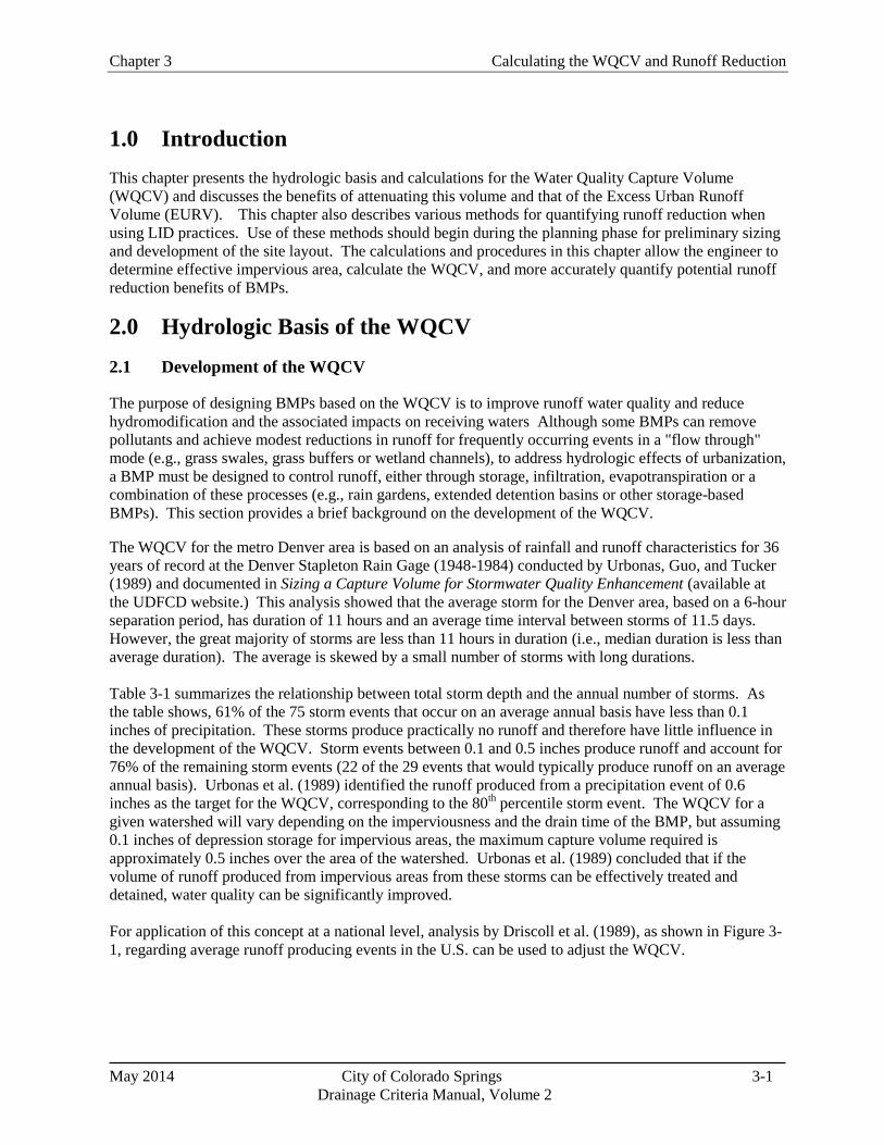
Chapter 3 Calculating the WQCV and Runoff Reduction
May 2014 City of Colorado Springs 3-1
Drainage Criteria Manual, Volume 2
1.0 Introduction
This chapter presents the hydrologic basis and calculations for the Water Quality Capture Volume
(WQCV) and discusses the benefits of attenuating this volume and that of the Excess Urban Runoff
Volume (EURV). This chapter also describes various methods for quantifying runoff reduction when
using LID practices. Use of these methods should begin during the planning phase for preliminary sizing
and development of the site layout. The calculations and procedures in this chapter allow the engineer to
determine effective impervious area, calculate the WQCV, and more accurately quantify potential runoff
reduction benefits of BMPs.
2.0 Hydrologic Basis of the WQCV
2.1 Development of the WQCV
The purpose of designing BMPs based on the WQCV is to improve runoff water quality and reduce
hydromodification and the associated impacts on receiving waters Although some BMPs can remove
pollutants and achieve modest reductions in runoff for frequently occurring events in a "flow through"
mode (e.g., grass swales, grass buffers or wetland channels), to address hydrologic effects of urbanization,
a BMP must be designed to control runoff, either through storage, infiltration, evapotranspiration or a
combination of these processes (e.g., rain gardens, extended detention basins or other storage-based
BMPs). This section provides a brief background on the development of the WQCV.
The WQCV for the metro Denver area is based on an analysis of rainfall and runoff characteristics for 36
years of record at the Denver Stapleton Rain Gage (1948-1984) conducted by Urbonas, Guo, and Tucker
(1989) and documented in Sizing a Capture Volume for Stormwater Quality Enhancement (available at
the UDFCD website.) This analysis showed that the average storm for the Denver area, based on a 6-hour
separation period, has duration of 11 hours and an average time interval between storms of 11.5 days.
However, the great majority of storms are less than 11 hours in duration (i.e., median duration is less than
average duration). The average is skewed by a small number of storms with long durations.
Table 3-1 summarizes the relationship between total storm depth and the annual number of storms. As
the table shows, 61% of the 75 storm events that occur on an average annual basis have less than 0.1
inches of precipitation. These storms produce practically no runoff and therefore have little influence in
the development of the WQCV. Storm events between 0.1 and 0.5 inches produce runoff and account for
76% of the remaining storm events (22 of the 29 events that would typically produce runoff on an average
annual basis). Urbonas et al. (1989) identified the runoff produced from a precipitation event of 0.6
inches as the target for the WQCV, corresponding to the 80th percentile storm event. The WQCV for a
given watershed will vary depending on the imperviousness and the drain time of the BMP, but assuming
0.1 inches of depression storage for impervious areas, the maximum capture volume required is
approximately 0.5 inches over the area of the watershed. Urbonas et al. (1989) concluded that if the
volume of runoff produced from impervious areas from these storms can be effectively treated and
detained, water quality can be significantly improved.
For application of this concept at a national level, analysis by Driscoll et al. (1989), as shown in Figure 3-
1, regarding average runoff producing events in the U.S. can be used to adjust the WQCV.
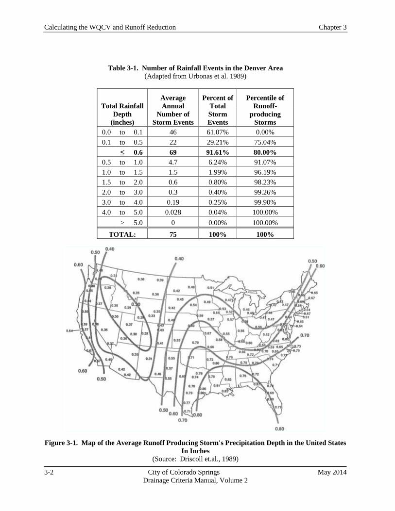
Calculating the WQCV and Runoff Reduction Chapter 3
3-2 City of Colorado Springs May 2014
Drainage Criteria Manual, Volume 2
Table 3-1. Number of Rainfall Events in the Denver Area
(Adapted from Urbonas et al. 1989)
Total Rainfall
Depth
(inches)
Average
Annual
Number of
Storm Events
Percent of
Total
Storm
Events
Percentile of
Runoff-
producing
Storms
0.0 to 0.1 46 61.07% 0.00%
0.1 to 0.5 22 29.21% 75.04%
≤ 0.6 69 91.61% 80.00%
0.5 to 1.0 4.7 6.24% 91.07%
1.0 to 1.5 1.5 1.99% 96.19%
1.5 to 2.0 0.6 0.80% 98.23%
2.0 to 3.0 0.3 0.40% 99.26%
3.0 to 4.0 0.19 0.25% 99.90%
4.0 to 5.0 0.028 0.04% 100.00%
> 5.0 0 0.00% 100.00%
TOTAL: 75 100% 100%
Figure 3-1. Map of the Average Runoff Producing Storm's Precipitation Depth in the United States
In Inches
(Source: Driscoll et.al., 1989)
Chapter 3 Calculating the WQCV and Runoff Reduction
May 2014 City of Colorado Springs 3-3
Drainage Criteria Manual, Volume 2
Based on rainfall data collected in the Fountain Creek watershed as described the Fountain Creek Rainfall
Characterization Study (Carlton, 2011) a similar analysis was completed. This analysis showed that the
rainfall patterns associated with small, frequent events in the Fountain Creek watershed are very similar to
those in the metro Denver area. Therefore, the requirements for WQCV used in metro Denver can be
applied within the Fountain Creek watershed. The analysis and its results are described in a
memorandum by WWE (May, 2012).
2.2 Optimizing the Capture Volume
Optimizing the capture volume is critical. If the capture volume is too small, the effectiveness of the
BMP will be reduced due to the frequency of storms exceeding the capacity of the facility and allowing
some volume of runoff to bypass treatment. On the other hand, if the capture volume for a BMP that
provides treatment through sedimentation is too large, the smaller runoff events may pass too quickly
through the facility, without the residence time needed to provide treatment.
Small, frequently occurring storms account for the predominant number of events that result in
stormwater runoff from urban catchments. Consequently, these frequent storms also account for a
significant portion of the annual pollutant loads. Capture and treatment of the stormwater from these
small and frequently occurring storms is required to satisfy the City’s MS4 Permit conditions.
The analysis of precipitation data at the Denver Stapleton Rain Gage revealed a relationship between the
percent imperviousness of a watershed and the capture volume needed to significantly reduce stormwater
pollutants (Urbonas, Guo, and Tucker, 1990). Subsequent studies (Guo and Urbonas, 1996 and Urbonas,
Roesner, and Guo, 1996) of precipitation resulted in a recommendation by the Water Environment
Federation and American Society of Civil Engineers (1998) that stormwater quality treatment facilities
(i.e., post-construction BMPs) be based on the capture and treatment of runoff from storms ranging in size
from "mean" to "maximized1" storms. The "mean" and "maximized" storm events represent the 70th and
90th percentile storms, respectively. As a result of these studies, water quality facilities for the Colorado
Front Range are recommended to capture and treat the 80th percentile runoff event. Capturing and
properly treating this volume should remove between 80 and 90% of the annual TSS load, while doubling
the capture volume was estimated to increase the removal rate by only 1 to 2%.
2.3 Attenuation of the WQCV (BMP Drain Time)
The WQCV must be released over an extended period to provide effective pollutant removal for post-
construction BMPs that use sedimentation (i.e., extended detention basin, retention ponds and constructed
wetland ponds). A field study of basins with extended detention in the Washington, D.C. area identified
an average drain time of 24 hours to be effective for extended detention basins. This generally equates to
a 40-hour drain time for the brim-full basin. Retention ponds and constructed wetland basins have
reduced drain times (12 hours and 24 hours, respectively) because the hydraulic residence time of the
effluent is essentially increased due to the mixing of the inflow with the permanent pool.
When pollutant removal is achieved primarily through filtration, such as in a sand filter or rain garden
BMP, an extended drain time is required to promote stability of downstream drainageways. In addition to
counteracting hydromodification, attenuation in filtering BMPs can also improve pollutant removal by
increasing contact time, which can aid adsorption/absorption processes depending on the media. The
1 The term "maximized storm" refers to the optimization of the storage volume of a BMP. The WQCV for the "maximized"
storm represents the point of diminishing returns in terms of the number of storm events and volume of runoff fully treated versus
the storage volume provided.
Calculating the WQCV and Runoff Reduction Chapter 3
3-4 City of Colorado Springs May 2014
Drainage Criteria Manual, Volume 2
minimum required drain time for a post-construction BMP is 12 hours for BMPs that do not rely fully or
partially on sedimentation for pollutant removal.
2.4 Excess Urban Runoff Volume (EURV) and Full Spectrum Detention
Capture and treatment of the EURV is required as part of the Full Spectrum Detention criteria that is
required in accordance with Chapter 3 – Drainage Policies in Volume 1. The EURV represents the
difference between the developed and pre-developed runoff volume for the range of storms that produce
runoff from pervious land surfaces (generally greater than the 2-year event). The EURV is relatively
constant for a given imperviousness over a wide range of storm events. This is a companion concept to
the WQCV. The EURV is a greater volume than the WQCV and is detained over a longer time. It
typically allows for the recommended drain time of the WQCV and is used to better replicate peak
discharge in receiving waters for runoff events exceeding the WQCV. The EURV is associated with Full
Spectrum Detention, a simplified sizing method for both water quality and flood control detention.
Designing a detention basin to capture the EURV and release it slowly (at a rate similar to WQCV release
rates) results in storms smaller than the 2-year event being reduced to flow rates much less than the
threshold value for erosion in most drainageways. In addition, by incorporating an outlet structure
designed per the criteria in this manual including an orifice or weir that limits 100-year runoff to the
allowable release rate, the storms greater than the 2-year event will be reduced to discharge rates and
hydrograph shapes that approximate pre-developed conditions. This reduces the likelihood that runoff
hydrographs from multiple basins will combine to produce greater peak discharges than pre-developed
conditions.
For the EURV and Full Spectrum Detention criteria and requirements, including calculation procedures,
please refer to the Storage chapter of Volume 1.
3.0 Calculation of the WQCV
The first step in estimating the magnitude of runoff from a site is to estimate the site's total
imperviousness. The total imperviousness of a site is the weighted average of individual areas of like
imperviousness. For instance, according to the Hydrology chapter of Volume 1 of this manual, paved
streets (and parking lots) have an imperviousness of 100%; drives, walks and roofs have an
imperviousness of 90%; and lawn areas have an imperviousness of 0%. The total imperviousness of a site
can be determined taking an area-weighted average of all of the impervious and pervious areas. These
impervious areas are assumed to be directly connected to the receiving systems beyond the site. When
measures are implemented to minimize directly connected impervious area (MDCIA), the effects of the
total imperviousness on the calculated WQCV can be represented by using an "effective imperviousness".
Sections 4 and 5 of this chapter provide guidance, requirements, and examples for calculating effective
imperviousness and adjusting the WQCV using this value.
The WQCV is calculated as a function of imperviousness and BMP drain time using Equation 3-1, and as
shown in Figure 3-2:
Equation 3-1
Where:
WQCV = Water Quality Capture Volume (watershed inches)
a = Coefficient corresponding to WQCV drain time (Table 3-2)

Chapter 3 Calculating the WQCV and Runoff Reduction
May 2014 City of Colorado Springs 3-5
Drainage Criteria Manual, Volume 2
I = Imperviousness (%)
Table 3-2. Drain Time Coefficients for WQCV Calculations
Drain Time (hrs) Coefficient, a
12 hours 0.8
24 hours 0.9
40 hours 1.0
Figure 3-2, which illustrates the relationship between imperviousness and WQCV for various drain times,
is appropriate for use in Colorado's high plains near the foothills. For other portions of Colorado or
United States, the WQCV obtained from this figure can be adjusted using the following relationships:
(
) Equation 3-2
Where:
WQCV = WQCV calculated using Equation 3-1 or Figure 3-2 (watershed inches)
WQCVother = WQCV outside of Denver region (watershed inches)
d6 = depth of average runoff producing storm from Figure 3-1 (watershed inches)
Once the WQCV in watershed inches is found from Figure 3-2 or using Equation 3-1 and/or 3-2, the
required BMP storage volume in acre-feet can be calculated as follows:
(
) Equation 3-3
Where:
V = required storage volume (acre-ft)
A = tributary catchment area upstream (acres)
WQCV = Water Quality Capture Volume (watershed inches)
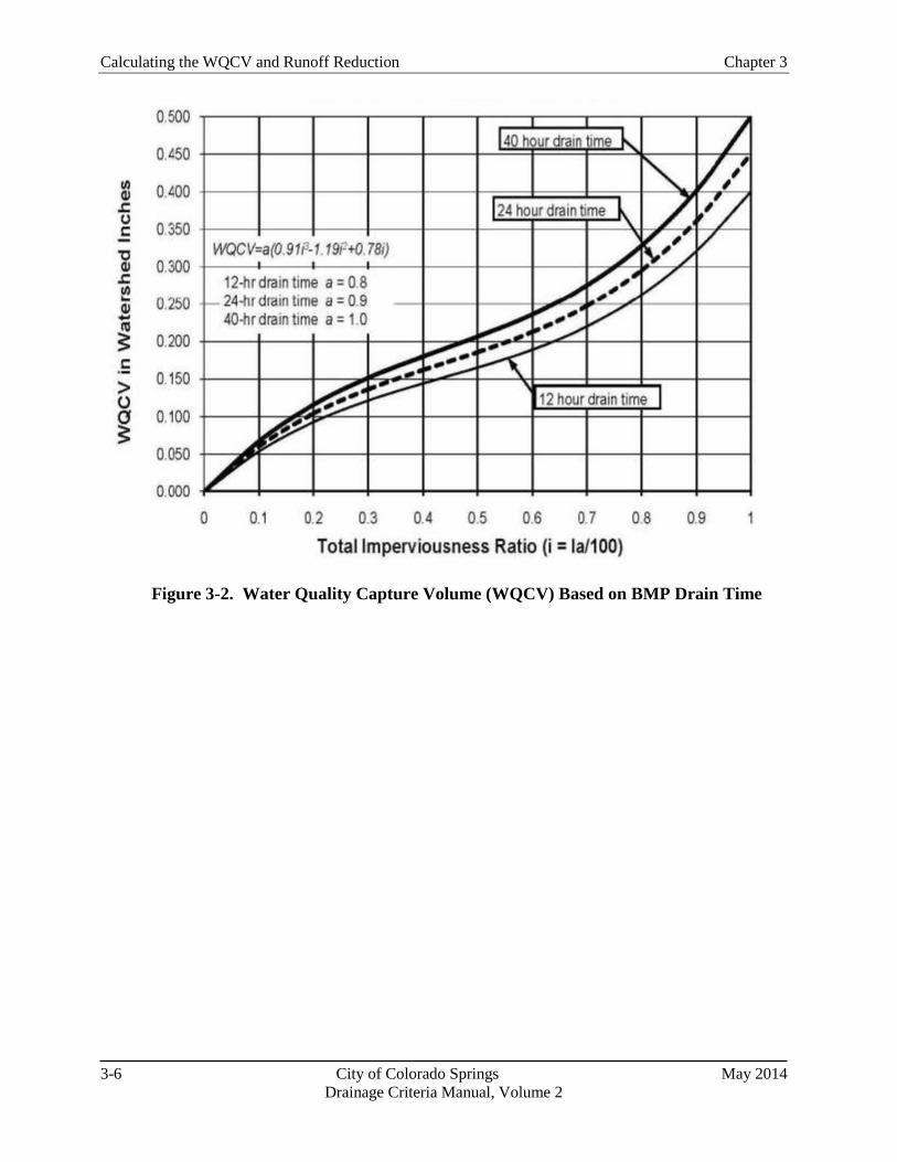
Calculating the WQCV and Runoff Reduction Chapter 3
3-6 City of Colorado Springs May 2014
Drainage Criteria Manual, Volume 2
Figure 3-2. Water Quality Capture Volume (WQCV) Based on BMP Drain Time

Chapter 3 Calculating the WQCV and Runoff Reduction
May 2014 City of Colorado Springs 3-7
Drainage Criteria Manual, Volume 2
Defining Effective Imperviousness
The concepts discussed in this section are
dependent on the concept of effective
imperviousness. This term refers to
impervious areas that contribute surface
runoff to the drainage system. For the
purposes of this manual, effective
imperviousness includes directly connected
impervious area and portions of the
unconnected impervious area that also
contribute to runoff from a site. For small,
frequently occurring events, the effective
imperviousness may be equivalent to
directly connected impervious area since
runoff from unconnected impervious areas
may infiltrate into receiving pervious areas;
however, for larger events, the effective
imperviousness is increased to account for
runoff from unconnected impervious areas
that exceeds the infiltration capacity of the
receiving pervious area. This means that
the calculation of effective imperviousness
is associated with a specific return period.
Note: Users should be aware that some
national engineering literature defines
effective imperviousness more narrowly to
include only directly connected impervious
area.
4.0 Quantifying Runoff Reduction
Runoff reduction is an important part of the Four Step
Process and is fundamental to effective stormwater
management. Quantifying runoff reduction associated
with MDCIA, LID practices and other BMPs is important
for watershed-level master planning and also for
conceptual and final site design. It also allows the
engineer to evaluate and compare the benefits of various
runoff reduction practices. This section describes the
conceptual model for evaluating runoff reduction and
provides tools for quantifying runoff reduction using
three different approaches, depending on the size of the
watershed, complexity of the design, and experience level
of the user. In this section, runoff reduction is evaluated
at the watershed level and at the site level.
4.1 Conceptual Model for Runoff Reduction
BMPs—Cascading Planes
The hydrologic response of a watershed during a storm
event is characterized by factors including shape, slope,
area, imperviousness (connected and disconnected) and
other factors (Guo 2006). As previously discussed, total
imperviousness of a watershed can be determined by
delineating roofs, drives, walks and other impervious
areas within a watershed and dividing the sum of these
impervious areas by the total watershed area. In the past,
total imperviousness was often used for calculation of
peak flow rates for design events and storage
requirements for water quality and flood control
purposes. This is a reasonable approach when much of the impervious area in a watershed is directly
connected to the drainage system; however, when the unconnected impervious area in a catchment is
significant, using total imperviousness will result in over-calculation of peak flow rates and storage
requirements.
To evaluate the effects of MDCIA and other LID practices, UDFCD has performed modeling using
SWMM to develop tools for planners and designers, both at the watershed/master planning level where
site-specific details have not been well defined, and at the site level, where plans are at more advanced
stages. Unlike many conventional stormwater models, SWMM allows for a relatively complex
evaluation of flow paths through the on-site stormwater BMP layout. Conceptually, an urban watershed
can be divided into four land use areas that drain to the common outfall point as shown in Figure 3-3,
including:
Directly Connected Impervious Area (DCIA)
Unconnected Impervious Area (UIA)
Receiving Pervious Area (RPA)
Separate Pervious Area (SPA)

Calculating the WQCV and Runoff Reduction Chapter 3
3-8 City of Colorado Springs May 2014
Drainage Criteria Manual, Volume 2
Figure 3-3. Four Component Land Use
A fundamental concept of LID is to route runoff generated from the UIA onto the RPA to increase
infiltration losses. To model the stormwater flows through a LID site, it is necessary to link flows
similarly to take into consideration additional depression storage and infiltration losses over the pervious
landscape. One of the more recent upgrades to SWMM allows users to model overland flow draining
from the upper impervious areas onto a downstream pervious area. As illustrated in Figure 3-3, the
effective imperviousness is only associated with the cascading plane from UIA to RPA, while the other
two areas, DCIA and SPA, are drained independently.
For a well-designed and properly constructed LID site, the effective imperviousness will be less than the
total imperviousness. This difference will be greatest for smaller, more frequently occurring events and
less for larger, less-frequent events. Aided by SWMM, effective imperviousness can be determined by a
runoff-volume weighting method that accounts for losses along the selected flow paths. When designing
a drainage system, design criteria that account for effective imperviousness can potentially reduce
stormwater costs by reducing the size of infrastructure to convey and/or store the design stormwater flows
and volumes. This chapter presents methods that allow the engineer to convert between total
imperviousness and effective imperviousness at both the watershed and site scales.
4.2 Watershed/Master Planning-level Runoff Reduction Method
For watershed-level assessments and master planning, NRCS (TR-55) provides guidance for users to
model effects of LID through adjustments to Curve Number for unconnected imperviousness.
Figure 3-4 can be used to estimate composite CNs for unconnected impervious areas. Runoff from these
areas is spread over a pervious area as sheet flow. To determine CN when all or part of the impervious
area is not directly connected to the drainage system, Figure 3-4 may be used if total imperviousness is
less than 30 percent. Otherwise the methods for estimating effective imperviousness described elsewhere
in this chapter may be used to estimate composite CNs.
Obtain the composite CN for unconnected impervious areas by entering the right half of Figure 3-4 with
the percentage of total impervious area and the ratio of total unconnected impervious area to total
impervious area. Then move left to the appropriate pervious CN and read down to find the composite
CN. For example, for a 1.2 acre lot with 20 percent total impervious area (75 percent of which is
unconnected) and pervious CN of 60, the composite CN from Figure 3-4 is 64. If all of the impervious
area is connected, the composite CN would be 68. Figure 3-4 is intended for use at the planning level

Chapter 3 Calculating the WQCV and Runoff Reduction
May 2014 City of Colorado Springs 3-9
Drainage Criteria Manual, Volume 2
when specifics of the site conditions are not yet well established.
It is notable that the reductions in effective imperviousness shown in Figure 3-4 are relatively modest.
When site-level details are still in conceptual stages, the use of effective impervious calculations and
composite unconnected CNs provides a tool for a master planning/watershed level assessment of effects
of disconnected impervious area. At a more advanced stage of design, when site-specific disconnected
areas, receiving pervious areas, flow paths, and other design details are available, the site-level methods
in Section 4.3 can be used to better quantify runoff reduction, and results will typically show greater
reductions in effective imperviousness for aggressive LID implementation than reflected in Figure 3-4.
Even so, to ensure compliance with the City’s requirement to capture and treat the EURV, it is unlikely
that conveyance-based BMPs alone will provide adequate pollutant removal and runoff reduction for
most project sites, and a storage-based BMP will also be required.
Figure 3-4. Composite Curve Number with Unconnected Imperviousness
(Source: TR-55, Figure 2-4)
4.3 Site-level Runoff Reduction Methods
Two options are available for quantification of runoff reduction at the site level when the DCIA, UIA,
RPA, and SPA fractions have been identified:
1. SWMM modeling using the cascading plane approach (must use Horton or Green Ampt for
infiltration;the CN method in EPA SWMM may produce different results than the NRCS CN
method), or
2. UDFCD Imperviousness Reduction Factor (IRF) charts and spreadsheet (located within the UD-BMP
workbook available at the UDFCD website)
The UDFCD IRF charts and spreadsheet were developed using a dimensionless SWMM modeling
Example: For Total Imp., I = 20%,
Unconnected Ratio= 0.75 and CNPervious = 60,
CNComposite = 64
Calculating the WQCV and Runoff Reduction Chapter 3
3-10 City of Colorado Springs May 2014
Drainage Criteria Manual, Volume 2
approach developed by Guo et al. (2010) that determines the effective imperviousness of a site based on
the total area-weighted imperviousness and the ratio of the infiltration rate (average infiltration rate based
on Green-Ampt ), f, to the rainfall intensity, I. Because the IRF is based on cascading plane SWMM
modeling, it will yield results that are generally consistent with creation of a site-specific SWMM model.
To apply either of the above methods, a project site must first be divided into sub-watersheds based on
topography and drainage patterns. For each sub-watershed, the areas of DCIA, UIA, RPA and SPA are
calculated. Sub-watersheds (and associated BMPs) will fall into one of two categories based on the types
of BMPs used:
1. Conveyance-based: Conveyance-based BMPs include grass swales, vegetated buffers, and
disconnection of roof drains and other impervious areas to drain to pervious areas (UDFCD 1999a).
Conveyance based BMPs may have some incidental, short-term storage in the form of channel
storage or shallow ponding, but do not provide the WQCV, EURV or flood-control detention volume.
2. Storage-based: Storage-based BMPs include rain gardens, permeable pavement systems as detailed
in this manual, extended detention basins and other BMPs in this manual that provide the WQCV,
EURV or flood control detention volume.
4.3.1 SWMM Modeling Using Cascading Planes
Because of complexities of modeling LID and other BMPs using SWMM, the cascading planes
alternative for site-level runoff reduction analysis is recommended only for experienced users. Guidance
for conveyance- and storage-based modeling includes these steps:
1. Each sub-watershed should be conceptualized as shown in Figure 3-3. Two approaches can be used
in SWMM to achieve this:
Create two SWMM sub-catchments for each sub-watershed, one with UIA 100% routed to RPA
and the other with DCIA and SPA independently routed to the outlet, or
Use a single SWMM sub-catchment to represent the sub-watershed and use the SWMM internal
routing option to differentiate between DCIA and UIA. This option should only be used when a
large portion of the pervious area on a site is RPA and there is very little SPA since the internal
routing does not have the ability to differentiate between SPA and RPA (i.e., the UIA is routed to
the entire pervious area, potentially overestimating infiltration losses).
2. Once the subwatershed is set up to represent UIA, DCIA, RPA and SPA in SWMM, the rainfall
distribution should be directly input to SWMM.
3. Parameters for infiltration, depression storage and other input parameters should be selected in
accordance with the guidance in the Hydrology chapter of Volume 1.
4. For storage-based BMPs, there are two options for representing the WQCV:
The pervious area depression storage value for the RPA can be increased to represent the WQCV.
This approach is generally applicable to storage-based BMPs that promote infiltration such as
rain gardens, permeable pavement systems with storage or sand filters. This adjustment should
not be used when a storage-based BMP has a well-defined outlet and a stage-storage-discharge
relationship that can be entered into SWMM.

Chapter 3 Calculating the WQCV and Runoff Reduction
May 2014 City of Colorado Springs 3-11
Drainage Criteria Manual, Volume 2
The WQCV can be modeled as a storage unit with an outlet in SWMM. This option is preferred
for storage-based BMPs with well-defined stage-storage-discharge relationships such as extended
detention basins.
These guidelines are applicable for EPA SWMM Version 5.0.018 and earlier versions going back to EPA
SWMM 5.0. EPA has developed SWMM Version 5.0.0.022 with enhanced LID modeling capabilities;
however, this version had not been fully vetted at the time this manual was released and should be applied
with caution.
4.3.2 IRF (K) Charts and Spreadsheet
When UIA, DCIA, RPA, SPA and WQCV, if any, for a site have been defined, this method provides a
relatively simple procedure for calculating effective imperviousness and runoff reduction.
Fundamentally, the IRF charts and spreadsheet are based on the following relationships.
For a conveyance-based approach:
(
) (
)
For a storage-based approach:
(
)
Where Fct designates a functional relationship and:
K = IRF (effective imperviousness/total imperviousness)
Fd = pervious area infiltration loss (in)
P = design rainfall depth (in)
Ar = RPA/UIA
f = pervious area average infiltration rate (in/hr)
I = rainfall intensity (in/hr)
Ad = RPA
WQCV = Water Quality Capture Volume (watershed inches)
A full derivation of equations based on these functional relationships can be found in Guo et al. (2010).
The results of cascading plane modeling based on these relationships is shown in Figure 3-5 for the
conveyance-based approach and Figure 3-6 for the storage-based approach.
Table 3-3 provides average infiltration rates that should be used for IRF calculations as a function of soil
type and drain time.

Calculating the WQCV and Runoff Reduction Chapter 3
3-12 City of Colorado Springs May 2014
Drainage Criteria Manual, Volume 2
Table 3-3. Infiltration Rates (f) for IRF Calculations
Soil Type
Conveyance-
based1
Storage-based
12-hours 24-hours 40-hours
(in/hr) (in/hr) (in/hr) (in/hr)
Sand 5.85 5.04 4.91 4.85
Loamy Sand 1.92 1.40 1.31 1.27
Sandy Loam 1.04 0.64 0.56 0.52
Silt Loam 0.83 0.46 0.39 0.35
Loam 0.43 0.24 0.20 0.18
Sandy Clay Loam 0.34 0.16 0.13 0.11
Silty Clay Loam 0.27 0.13 0.10 0.08
Clay Loam 0.26 0.13 0.10 0.08
Silty Clay 0.18 0.08 0.06 0.05
Sandy Clay 0.16 0.08 0.06 0.05
Clay 0.12 0.05 0.04 0.03 1 Values for conveyance-based BMPs are based on a 2-hour duration.
When using Figure 3-5 and Figure 3-6, it is important to understand that the curves are based on ratios of
infiltration and precipitation rates, not depths. Therefore the f/I = 2.0 curve could represent soils with an
average infiltration rate of 1 inch per hour and an event with a total precipitation of 0.5 inches in 1 hour
(i.e., an event with a total depth that is roughly the same as the WQCV) or a longer event, such as 2.0
inches over 4 hours, which still would have a rainfall intensity of 0.5 inches per hour but that would have
a total precipitation depth and overall runoff volume greater than the WQCV. Therefore, when using the
storage-based curves in Figure 3-6 for small events, it is important to check the total precipitation depth as
well as the f/I ratio. In cases where the total precipitation depth is less than 0.6 inches and the full WQCV
is provided, the IRF, represented as K, can be set to 0 because all of the runoff will be captured by the
storage-based BMP and released over an extended period, having minimal downstream effect on the
timescale of an event. The UD-BMP worksheet approximates one-hour precipitation intensity as the one
hour point precipitation depth and performs a check of the precipitation depth relative to the WQCV,
assigning K = 0, when the precipitation depth is less than the WQCV for storage-based BMPs.
Once K is known for a given storm event, the following equation can be used to calculate the effective
imperviousness for that event:
(
)
Equation 3-4
Where:
DCIA = directly connected impervious area
UIA = unconnected impervious area
RPA = receiving pervious area
SPA = separate pervious area

Chapter 3 Calculating the WQCV and Runoff Reduction
May 2014 City of Colorado Springs 3-13
Drainage Criteria Manual, Volume 2
Figure 3-5. Conveyance-based Imperviousness Reduction Factor
Figure 3-6. Storage-based Imperviousness Reduction Factor
0.0
0.1
0.2
0.3
0.4
0.5
0.6
0.7
0.8
0.9
1.0
0% 10% 20% 30% 40% 50% 60% 70% 80% 90% 100%
Imp
erv
iou
sne
ss R
ed
uct
ion
Fac
tor
(IR
F), K
Area-weighted Imperviousness of Disconnected Portion (%) = UIA/(UIA+RPA)
f/I = 0.5 f/I = 1.0 f/I = 1.5 f/I = 2.0
0.0
0.1
0.2
0.3
0.4
0.5
0.6
0.7
0.8
0.9
1.0
0% 10% 20% 30% 40% 50% 60% 70% 80% 90% 100%
Imp
erv
iou
sne
ss R
ed
uct
ion
Fac
tor
(IR
F), K
Area-weighted Imperviousness of Disconnected Portion (%) = UIA/(UIA+RPA)
f/I = 0.5 f/I = 1.0 f/I = 1.5 f/I = 2.0
Note: When the total depth of the storm event is less than the WQCV and the full WQCV is provided for a sub-basin, K = 0.
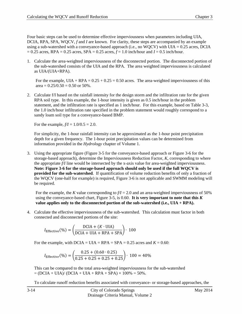
Calculating the WQCV and Runoff Reduction Chapter 3
3-14 City of Colorado Springs May 2014
Drainage Criteria Manual, Volume 2
Four basic steps can be used to determine effective imperviousness when parameters including UIA,
DCIA, RPA, SPA, WQCV, f and I are known. For clarity, these steps are accompanied by an example
using a sub-watershed with a conveyance-based approach (i.e., no WQCV) with UIA = 0.25 acres, DCIA
= 0.25 acres, RPA = 0.25 acres, SPA = 0.25 acres, f = 1.0 inch/hour and I = 0.5 inch/hour.
1. Calculate the area-weighted imperviousness of the disconnected portion. The disconnected portion of
the sub-watershed consists of the UIA and the RPA. The area weighted imperviousness is calculated
as UIA/(UIA+RPA).
For the example, UIA + RPA = 0.25 + 0.25 = 0.50 acres. The area-weighted imperviousness of this
area = 0.25/0.50 = 0.50 or 50%.
2. Calculate f/I based on the rainfall intensity for the design storm and the infiltration rate for the given
RPA soil type. In this example, the 1-hour intensity is given as 0.5 inch/hour in the problem
statement, and the infiltration rate is specified as 1 inch/hour. For this example, based on Table 3-3,
the 1.0 inch/hour infiltration rate specified in the problem statement would roughly correspond to a
sandy loam soil type for a conveyance-based BMP.
For the example, f/I = 1.0/0.5 = 2.0.
For simplicity, the 1-hour rainfall intensity can be approximated as the 1-hour point precipitation
depth for a given frequency. The 1-hour point precipitation values can be determined from
information provided in the Hydrology chapter of Volume 1.
3. Using the appropriate figure (Figure 3-5 for the conveyance-based approach or Figure 3-6 for the
storage-based approach), determine the Imperviousness Reduction Factor, K, corresponding to where
the appropriate f/I line would be intersected by the x-axis value for area-weighted imperviousness.
Note: Figure 3-6 for the storage-based approach should only be used if the full WQCV is
provided for the sub-watershed. If quantification of volume reduction benefits of only a fraction of
the WQCV (one-half for example) is required, Figure 3-6 is not applicable and SWMM modeling will
be required.
For the example, the K value corresponding to f/I = 2.0 and an area-weighted imperviousness of 50%
using the conveyance-based chart, Figure 3-5, is 0.60. It is very important to note that this K
value applies only to the disconnected portion of the sub-watershed (i.e., UIA + RPA).
4. Calculate the effective imperviousness of the sub-watershed. This calculation must factor in both
connected and disconnected portions of the site:
(
)
For the example, with DCIA = UIA = RPA = SPA = 0.25 acres and K = 0.60:
(
)
This can be compared to the total area-weighted imperviousness for the sub-watershed
= (DCIA + UIA)/ (DCIA + UIA + RPA + SPA) × 100% = 50%.
To calculate runoff reduction benefits associated with conveyance- or storage-based approaches, the
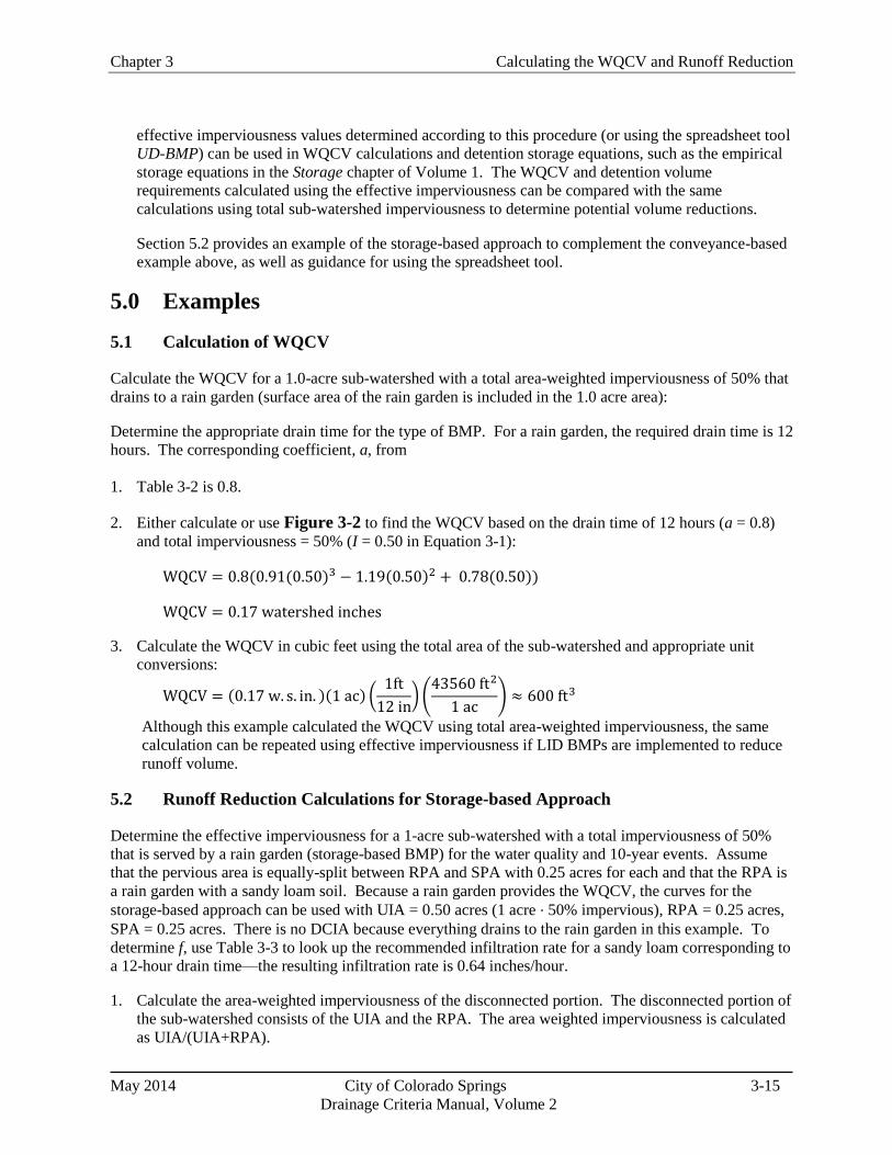
Chapter 3 Calculating the WQCV and Runoff Reduction
May 2014 City of Colorado Springs 3-15
Drainage Criteria Manual, Volume 2
effective imperviousness values determined according to this procedure (or using the spreadsheet tool
UD-BMP) can be used in WQCV calculations and detention storage equations, such as the empirical
storage equations in the Storage chapter of Volume 1. The WQCV and detention volume
requirements calculated using the effective imperviousness can be compared with the same
calculations using total sub-watershed imperviousness to determine potential volume reductions.
Section 5.2 provides an example of the storage-based approach to complement the conveyance-based
example above, as well as guidance for using the spreadsheet tool.
5.0 Examples
5.1 Calculation of WQCV
Calculate the WQCV for a 1.0-acre sub-watershed with a total area-weighted imperviousness of 50% that
drains to a rain garden (surface area of the rain garden is included in the 1.0 acre area):
Determine the appropriate drain time for the type of BMP. For a rain garden, the required drain time is 12
hours. The corresponding coefficient, a, from
1. Table 3-2 is 0.8.
2. Either calculate or use Figure 3-2 to find the WQCV based on the drain time of 12 hours (a = 0.8)
and total imperviousness = 50% (I = 0.50 in Equation 3-1):
3. Calculate the WQCV in cubic feet using the total area of the sub-watershed and appropriate unit
conversions:
(
) (
)
Although this example calculated the WQCV using total area-weighted imperviousness, the same
calculation can be repeated using effective imperviousness if LID BMPs are implemented to reduce
runoff volume.
5.2 Runoff Reduction Calculations for Storage-based Approach
Determine the effective imperviousness for a 1-acre sub-watershed with a total imperviousness of 50%
that is served by a rain garden (storage-based BMP) for the water quality and 10-year events. Assume
that the pervious area is equally-split between RPA and SPA with 0.25 acres for each and that the RPA is
a rain garden with a sandy loam soil. Because a rain garden provides the WQCV, the curves for the
storage-based approach can be used with UIA = 0.50 acres (1 acre ∙ 50% impervious), RPA = 0.25 acres,
SPA = 0.25 acres. There is no DCIA because everything drains to the rain garden in this example. To
determine f, use Table 3-3 to look up the recommended infiltration rate for a sandy loam corresponding to
a 12-hour drain time—the resulting infiltration rate is 0.64 inches/hour.
1. Calculate the area-weighted imperviousness of the disconnected portion. The disconnected portion of
the sub-watershed consists of the UIA and the RPA. The area weighted imperviousness is calculated
as UIA/(UIA+RPA).

Calculating the WQCV and Runoff Reduction Chapter 3
3-16 City of Colorado Springs May 2014
Drainage Criteria Manual, Volume 2
For the example, UIA + RPA = 0.50 + 0.25 = 0.75 acres. The area-weighted imperviousness of this
area = 0.50/0.75 = 0.67 or 67%.
2. Determine rainfall intensities for calculation of f/I ratios. For the water quality event, which is
roughly an 80th percentile event, there is no specified duration, so assume rainfall intensity based on a
1-hour duration, giving an intensity of approximately 0.6 inches/hour. For the water quality event,
this is generally a conservative assumption since the runoff that enters the rain garden will have a
mean residence time in the facility of much more than 1 hour. For the 10-year event, the 1-hour point
rainfall depth from the Hydrology chapter, Volume 1, can be used to approximate the rainfall
intensity for calculation of the f/I ratio. For this example, the 1-hour point precipitation for the 10-
year event is approximately 1.55 inches, equating to an intensity of 1.55 inches/hour.
3. Calculate f/I based on the design rainfall intensity (0.6 inches/hour) and RPA infiltration rate from
Table 3-3 (0.64 inches/hour).
For the water quality event, f/I = 0.64/0.6 = 1.07.
For the 10-year event, f/I = 0.64/1.55 = 0.41.
4. Using the appropriate figure (Figure 3-6 for the storage-based approach in this case), determine the
Imperviousness Reduction Factor K, corresponding to where the appropriate f/I line would be
intersected by the x-axis value for area-weighted imperviousness.
For the water quality event, the K value corresponding to f/I = 1.07 and an area-weighted
imperviousness of 50% using the storage-based chart, Figure 3-6, would be approximately 0.64;
however, because the total depth of the water quality event is provided as the WQCV for the storage-
based rain garden, K is reduced to 0 for the water quality event.
For the 10-year event, the K value corresponding to f/I = 0.41 and an area-weighted imperviousness
of 50% using the storage-based chart, Figure 3-6, is approximately 0.94.
It is very important to note that these K values apply only to the disconnected portion of the
sub-watershed (i.e., UIA + RPA). If this example included DCIA, the total imperviousness would
be higher.
5. Calculate the effective imperviousness of the sub-watershed. This calculation must factor in both
connected and disconnected portions of the site:
(
)
For the water quality event, with DCIA = 0 acres, UIA = 0.5 acres and RPA = SPA = 0.25 acres,
with K = 0:
(
)
For the 10-year event, with DCIA = 0 acres, UIA = 0.5 acres and RPA = SPA = 0.25 acres, with K =
0.94:
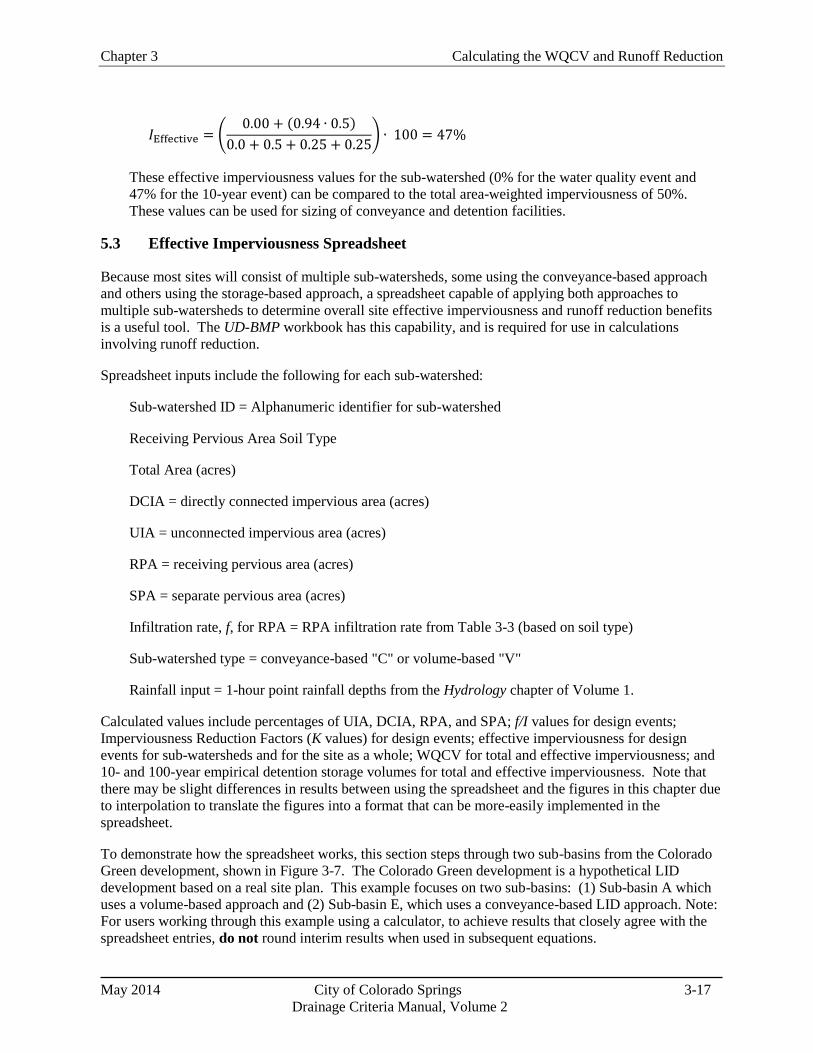
Chapter 3 Calculating the WQCV and Runoff Reduction
May 2014 City of Colorado Springs 3-17
Drainage Criteria Manual, Volume 2
(
)
These effective imperviousness values for the sub-watershed (0% for the water quality event and
47% for the 10-year event) can be compared to the total area-weighted imperviousness of 50%.
These values can be used for sizing of conveyance and detention facilities.
5.3 Effective Imperviousness Spreadsheet
Because most sites will consist of multiple sub-watersheds, some using the conveyance-based approach
and others using the storage-based approach, a spreadsheet capable of applying both approaches to
multiple sub-watersheds to determine overall site effective imperviousness and runoff reduction benefits
is a useful tool. The UD-BMP workbook has this capability, and is required for use in calculations
involving runoff reduction.
Spreadsheet inputs include the following for each sub-watershed:
Sub-watershed ID = Alphanumeric identifier for sub-watershed
Receiving Pervious Area Soil Type
Total Area (acres)
DCIA = directly connected impervious area (acres)
UIA = unconnected impervious area (acres)
RPA = receiving pervious area (acres)
SPA = separate pervious area (acres)
Infiltration rate, f, for RPA = RPA infiltration rate from Table 3-3 (based on soil type)
Sub-watershed type = conveyance-based "C" or volume-based "V"
Rainfall input = 1-hour point rainfall depths from the Hydrology chapter of Volume 1.
Calculated values include percentages of UIA, DCIA, RPA, and SPA; f/I values for design events;
Imperviousness Reduction Factors (K values) for design events; effective imperviousness for design
events for sub-watersheds and for the site as a whole; WQCV for total and effective imperviousness; and
10- and 100-year empirical detention storage volumes for total and effective imperviousness. Note that
there may be slight differences in results between using the spreadsheet and the figures in this chapter due
to interpolation to translate the figures into a format that can be more-easily implemented in the
spreadsheet.
To demonstrate how the spreadsheet works, this section steps through two sub-basins from the Colorado
Green development, shown in Figure 3-7. The Colorado Green development is a hypothetical LID
development based on a real site plan. This example focuses on two sub-basins: (1) Sub-basin A which
uses a volume-based approach and (2) Sub-basin E, which uses a conveyance-based LID approach. Note:
For users working through this example using a calculator, to achieve results that closely agree with the
spreadsheet entries, do not round interim results when used in subsequent equations.
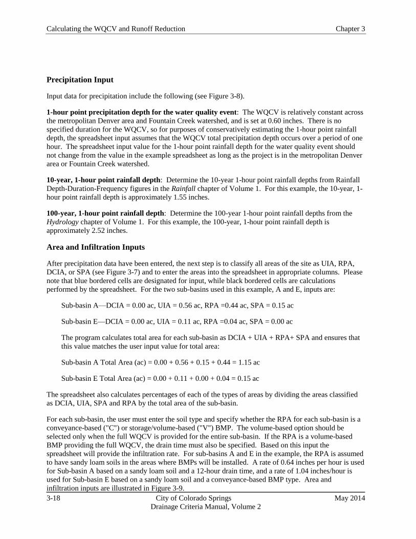
Calculating the WQCV and Runoff Reduction Chapter 3
3-18 City of Colorado Springs May 2014
Drainage Criteria Manual, Volume 2
Precipitation Input
Input data for precipitation include the following (see Figure 3-8).
1-hour point precipitation depth for the water quality event: The WQCV is relatively constant across
the metropolitan Denver area and Fountain Creek watershed, and is set at 0.60 inches. There is no
specified duration for the WQCV, so for purposes of conservatively estimating the 1-hour point rainfall
depth, the spreadsheet input assumes that the WQCV total precipitation depth occurs over a period of one
hour. The spreadsheet input value for the 1-hour point rainfall depth for the water quality event should
not change from the value in the example spreadsheet as long as the project is in the metropolitan Denver
area or Fountain Creek watershed.
10-year, 1-hour point rainfall depth: Determine the 10-year 1-hour point rainfall depths from Rainfall
Depth-Duration-Frequency figures in the Rainfall chapter of Volume 1. For this example, the 10-year, 1-
hour point rainfall depth is approximately 1.55 inches.
100-year, 1-hour point rainfall depth: Determine the 100-year 1-hour point rainfall depths from the
Hydrology chapter of Volume 1. For this example, the 100-year, 1-hour point rainfall depth is
approximately 2.52 inches.
Area and Infiltration Inputs
After precipitation data have been entered, the next step is to classify all areas of the site as UIA, RPA,
DCIA, or SPA (see Figure 3-7) and to enter the areas into the spreadsheet in appropriate columns. Please
note that blue bordered cells are designated for input, while black bordered cells are calculations
performed by the spreadsheet. For the two sub-basins used in this example, A and E, inputs are:
Sub-basin A—DCIA = 0.00 ac, UIA = 0.56 ac, RPA =0.44 ac, SPA = 0.15 ac
Sub-basin E—DCIA = 0.00 ac, UIA = 0.11 ac, RPA =0.04 ac, SPA = 0.00 ac
The program calculates total area for each sub-basin as DCIA + UIA + RPA+ SPA and ensures that
this value matches the user input value for total area:
Sub-basin A Total Area (ac) = 0.00 + 0.56 + 0.15 + 0.44 = 1.15 ac
Sub-basin E Total Area (ac) = 0.00 + 0.11 + 0.00 + 0.04 = 0.15 ac
The spreadsheet also calculates percentages of each of the types of areas by dividing the areas classified
as DCIA, UIA, SPA and RPA by the total area of the sub-basin.
For each sub-basin, the user must enter the soil type and specify whether the RPA for each sub-basin is a
conveyance-based ("C") or storage/volume-based ("V") BMP. The volume-based option should be
selected only when the full WQCV is provided for the entire sub-basin. If the RPA is a volume-based
BMP providing the full WQCV, the drain time must also be specified. Based on this input the
spreadsheet will provide the infiltration rate. For sub-basins A and E in the example, the RPA is assumed
to have sandy loam soils in the areas where BMPs will be installed. A rate of 0.64 inches per hour is used
for Sub-basin A based on a sandy loam soil and a 12-hour drain time, and a rate of 1.04 inches/hour is
used for Sub-basin E based on a sandy loam soil and a conveyance-based BMP type. Area and
infiltration inputs are illustrated in Figure 3-9.

Chapter 3 Calculating the WQCV and Runoff Reduction
May 2014 City of Colorado Springs 3-19
Drainage Criteria Manual, Volume 2
AR and f/I Calculations
After area and RPA infiltration parameters are input, the spreadsheet performs calculations of the AR ratio
and f/I parameters for design storm events including the water quality event and the 10- and 100-year
events. Spreadsheet calculations are shown in Figure 3-10.
Calculations for Sub-basin A include the following:
In general, the higher this ratio is, the greater the potential for infiltration and runoff reduction.
This is mathematically equivalent to UIA/(RPA+UIA) = 0.56/(0.44+0.56).
Next the spreadsheet calculates f/I parameters using the RPA infiltration rate and the 1-hour maximum
intensity values for each event (values in the spreadsheet are rounded to the tenths place). Values for
Sub-basin A include:
Calculations for Sub-basin E include the following:
This is mathematically equivalent to UIA/(RPA+UIA) = 0.11/(0.04+0.11).
f/I calculations for Sub-basin E include:

Calculating the WQCV and Runoff Reduction Chapter 3
3-20 City of Colorado Springs May 2014
Drainage Criteria Manual, Volume 2
IRF (K) and Effective Impervious Calculations
The next set of calculations determines the Impervious Reduction Factors (K values) for each design
event and the effective imperviousness of the overall sub-basins.
Note: In the spreadsheet, the abbreviation "IRF" is used interchangeably with "K."
Calculation of the K value is based on a lookup table in the spreadsheet containing the data used to create
Figures 3-5 and 3-6.
For the example, Sub-basin A is designated as "V-12" (volume-based BMP with a 12-hour drain time)
and Sub-basin E is designated as "C" (conveyance-based). Calculations for IRF and effective
imperviousness parameters provided below are shown in Figure 3-10.
Calculations for Sub-basin A include the following:
The results from the lookup table can be compared against Figure 3-6 (volume-based curves) as a check.
The K values can be read off Figure 3-6 using UIA/(RPA + UIA) = 0.56 (56%) and f/I = 1.1, 0.4 and 0.2
for the water quality, 10- and 100-year events respectively. Figure 3-11 illustrates the readings from the
volume-based figure.
Calculations for Sub-basin E include the following:
The results from the lookup table can be compared against Figure 3-5 (conveyance-based curves). The
IRF values can be read off Figure 3-5 using UIA/(RPA + UIA) = 0.73 (73%) and f/I = 1.7, 0.7 and 0.4 for
the water quality, 10- and 100-year events respectively. Figure 3-12 illustrates the readings from the
conveyance-based figure.
The next step, illustrated in Figure 3-10, is to calculate the effective imperviousness for the water quality,
10- and 100-year events for the entire sub-basin. Note that the K value is only applied to the UIA and
RPA portions of the sub-basins.
Calculations for Sub-basin A include the following:

Chapter 3 Calculating the WQCV and Runoff Reduction
May 2014 City of Colorado Springs 3-21
Drainage Criteria Manual, Volume 2
Note: Because the "V" option was selected in the spreadsheet, the effective imperviousness is set to 0.0
for the WQ event/WQCV (i.e., if the full WQCV is provided by a BMP and an event with less
precipitation and runoff than the water quality design event occurs, the BMP will completely treat the
runoff from the event, either infiltrating or releasing the runoff in a controlled manner, effectively making
the imperviousness of the area on the timescale of the event approximately zero). In order for IWQ to be
set to 0.0 for the water quality event, the full WQCV must be provided for the entire sub-basin.
Calculations for Sub-basin E include the following:
Water Quality Capture Volume and 10- and 100-year Detention Volume Adjustments
Once the effective imperviousness values are calculated for the sub-basins, the adjusted, effective
imperviousness values can be used in drainage calculations for conveyance and storage to quantify
benefits of conveyance- and storage-based BMPs. Spreadsheet calculations are shown in Figure 3-10.
WQCV
To quantify the benefits of disconnected impervious area and other BMPs on the WQCV, the WQCV is
calculated using both the total imperviousness and effective imperviousness of each sub-basin.
Calculations for Sub-basin A include the following:
(
)
Since the volume-based option is specified for Sub-basin A, by definition, the entire WQCV (846 ft3) is to

Calculating the WQCV and Runoff Reduction Chapter 3
3-22 City of Colorado Springs May 2014
Drainage Criteria Manual, Volume 2
be provided. Therefore, there is no need to calculate WQCV IWQ for Sub-basin A. The spreadsheet
returns the result "N/A." The effects of providing the WQCV for Sub-basin A lead to reductions in
detention storage requirements for the 10- and 100-year events as demonstrated below.
Calculations for Sub-basin E include the following:
(
)
Next, the WQCV associated with IWQ is calculated:
(
)
Therefore, the reduction in the required WQCV from the implementation of conveyance-based BMPs in
Sub-basin E is approximately 158 ft3 – 122 ft
3 = 36 ft
3, or approximately 23% relative to the WQCV
based on total imperviousness.
10-Year Event
To evaluate effects of conveyance- and volume-based BMPs on 10-year detention storage volumes, the
empirical equations from the Storage chapter of Volume 1 can be applied to the total impervious area and
the effective imperviousness. The results of these calculations can be compared to determine the
associated 10-year volume reduction.
Calculations for Sub-basin A include the following:
The same calculation is then performed using the effective imperviousness for the 10-year event:
( )
The reduction in the 10-year storage volume as a result of the conveyance-based BMPs in Sub-basin A is,
therefore, 2222 ft3 – 2046 ft
3 = 176 ft
3, or approximately 8% relative to the 10-year storage volume based
on total imperviousness.
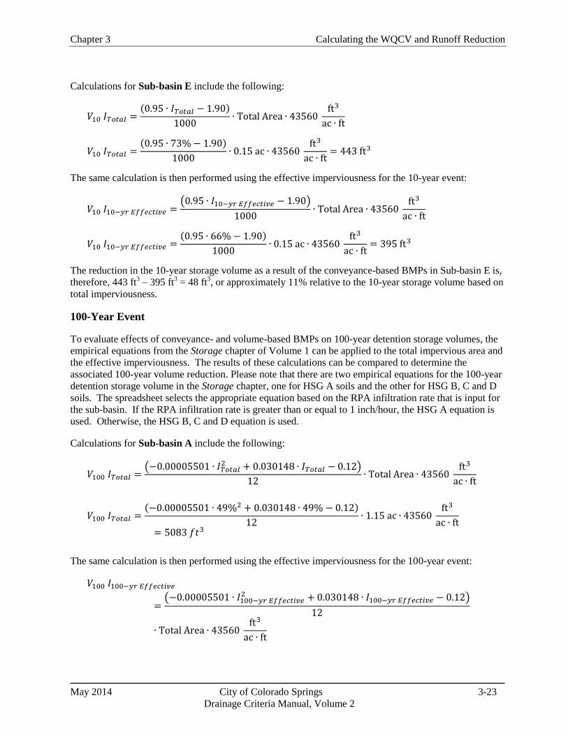
Chapter 3 Calculating the WQCV and Runoff Reduction
May 2014 City of Colorado Springs 3-23
Drainage Criteria Manual, Volume 2
Calculations for Sub-basin E include the following:
The same calculation is then performed using the effective imperviousness for the 10-year event:
( )
The reduction in the 10-year storage volume as a result of the conveyance-based BMPs in Sub-basin E is,
therefore, 443 ft3 – 395 ft
3 = 48 ft
3, or approximately 11% relative to the 10-year storage volume based on
total imperviousness.
100-Year Event
To evaluate effects of conveyance- and volume-based BMPs on 100-year detention storage volumes, the
empirical equations from the Storage chapter of Volume 1 can be applied to the total impervious area and
the effective imperviousness. The results of these calculations can be compared to determine the
associated 100-year volume reduction. Please note that there are two empirical equations for the 100-year
detention storage volume in the Storage chapter, one for HSG A soils and the other for HSG B, C and D
soils. The spreadsheet selects the appropriate equation based on the RPA infiltration rate that is input for
the sub-basin. If the RPA infiltration rate is greater than or equal to 1 inch/hour, the HSG A equation is
used. Otherwise, the HSG B, C and D equation is used.
Calculations for Sub-basin A include the following:
(
)
The same calculation is then performed using the effective imperviousness for the 100-year event:
(
)

Calculating the WQCV and Runoff Reduction Chapter 3
3-24 City of Colorado Springs May 2014
Drainage Criteria Manual, Volume 2
The reduction in the 100-year storage volume, as a result of the conveyance-based BMPs in Sub-basin A,
is 5083 ft3 – 4865 ft
3 = 218 ft
3, a reduction of approximately 4.3%.
Calculations for Sub-basin E include the following:
(
)
The same calculation is then performed using the effective imperviousness for the 100-year event:
(
)
The reduction in the 100-year storage volume as a result of the volume-based BMPs in Sub-basin E is,
therefore, 977ft3 – 927 ft
3 = 50 ft
3, a reduction of approximately 5%.
6.0 Conclusion
This chapter provides the computational procedures necessary to calculate the WQCV and adjust
imperviousness values used in these calculations due to implementation of LID/MDCIA in the tributary
watershed. The resulting WQCV can then be combined with BMP specific design criteria in Chapter 4 to
complete the BMP design(s). Adjustments to imperviousness and Curve Numbers resulting from these
procedures can be used as input into methods for estimating runoff described in the Hydrology chapter of
Volume 1 and for sizing storage volumes described in the Storage chapter of Volume 1.

Chapter 3 Calculating the WQCV and Runoff Reduction
May 2014 City of Colorado Springs 3-25
Drainage Criteria Manual, Volume 2
Fig
ure
3-7
. C
olo
rad
o G
reen
Dev
elop
men
t D
CIA
, U
IA,
RP
A,
an
d S
PA

Calculating the WQCV and Runoff Reduction Chapter 3
3-26 City of Colorado Springs May 2014
Drainage Criteria Manual, Volume 2
Figure 3-8. Colorado Green Precipitation Input Screen Shot
Figure 3-9. Colorado Green Area and Infiltration Input Screen Shot
Figure 3-10. Colorado Green Calculated Output Screen Shot
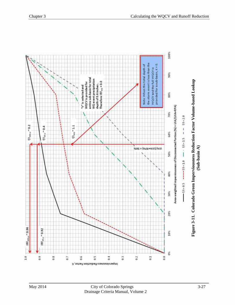
Chapter 3 Calculating the WQCV and Runoff Reduction
May 2014 City of Colorado Springs 3-27
Drainage Criteria Manual, Volume 2
Fig
ure
3-1
1. C
olo
rad
o G
reen
Im
per
vio
usn
ess
Red
uct
ion
Fact
or
Volu
me-b
ase
d L
oo
ku
p
(Su
b-b
asi
n A
)

Calculating the WQCV and Runoff Reduction Chapter 3
3-28 City of Colorado Springs May 2014
Drainage Criteria Manual, Volume 2
Figure 3-12. Colorado Green IRF Conveyance-based Lookup
(Sub basin E)

Chapter 3 Calculating the WQCV and Runoff Reduction
May 2014 City of Colorado Springs 3-29
Drainage Criteria Manual, Volume 2
7.0 References
Driscoll, E., G. Palhegyi, E. Strecker, and P. Shelley. 1990. Analysis of Storm Event Characteristics for
Selected Rainfall Gauges Throughout the United States. Prepared for the U.S. Environmental
Protection Agency (EPA). Woodward-Clyde Consultants: Oakland, CA.
Guo, James C.Y., E. G. Blackler, A. Earles, and Ken Mackenzie. Accepted 2010. Effective
Imperviousness as Incentive Index for Stormwater LID Designs. Pending publication in ASCE J.
of Environmental Engineering.
Guo, James C.Y. 2006. Urban Hydrology and Hydraulic Design. Water Resources Publications, LLC.:
Highlands Ranch, Colorado.
Guo, James C.Y. and Ben Urbonas. 1996. Maximized Detention Volume Determined by Runoff Capture
Rate. ASCE Journal of Water Resources Planning and Management, Vol. 122, No 1, January.
Urbonas, B., L. A. Roesner, and C. Y. Guo. 1996. Hydrology for Optimal Sizing of Urban Runoff
Treatment Control Systems. Water Quality International. International Association for Water
Quality: London, England.
Urbonas B., J. C. Y. Guo, and L. S. Tucker. 1989 updated 1990. Sizing Capture Volume for Stormwater
Quality Enhancement. Flood Hazard News. Urban Drainage and Flood Control District:
Denver, CO.
Water Environment Federation and American Society of Civil Engineers. 1998. Urban Runoff Quality
Management. WEF Manual of Practice No. 23. ASCE Manual and Report on Engineering
Practice No. 87.

May 2014 City of Colorado Springs 4-i
Drainage Criteria Manual, Volume 2
Chapter 4
Treatment BMPs
Contents
1.0 Overview ........................................................................................................................................... 1
2.0 Definition of New Development and Redevelopment/BMP Requirements ................................ 1
3.0 Submittals ......................................................................................................................................... 2
4.0 Underground BMPs ......................................................................................................................... 3
5.0 Alternate BMPs ................................................................................................................................ 3
6.0 Fact Sheets ........................................................................................................................................ 3
Chapter 4 Treatment BMPs
May 2014 City of Colorado Springs 4-1
Drainage Criteria Manual, Volume 2
1.0 Overview
This chapter contains guidance and design requirements for structural Best Management Practices
(BMPs) for new development and significant redevelopment as defined in the following sections. As
discussed in Chapter 2, BMPs provide treatment through a variety of hydrologic, physical, biological, and
chemical processes. The functions provided by BMPs may include volume reduction, treatment and slow
release of the water quality capture volume (WQCV), and combined water quality/flood detention.
Ideally, site designs will include a variety of source control and treatment BMPs combined in a "treatment
train" that controls pollutants at their sources, reduces runoff, and treats pollutants in runoff. Sites that are
well designed for treatment of urban runoff will include all of the steps in the Four Step Process discussed
in Chapter 1. The minimum measures required for development projects to satisfy the City’s MS4 permit
requirements are described in Section 4.1 of Chapter 1.This chapter hereby incorporates by reference all
criteria presented in the current version of the Urban Storm Drainage Criteria Manual (USDCM), Volume
3, Best Management Practices, Chapter 4 Treatment BMPs for purposes of design and implementation,
except as modified herein. Detailed descriptions, sizing and design criteria, and design procedures for
these BMPs are provided in the USDCM, V3 Treatment BMP Fact Sheets.
Runoff from all impervious surfaces of a site must flow through a properly designed installation of one or
more of the WQCV BMPs presented in this Chapter. All new and significant redevelopment with
construction activities that disturb equal to or greater than 1 acre, including projects less than one acre that
are part of a larger common plan of development or sale must assess the existing and planned water
quality treatment for the drainage basin in which the development lies. For basins that have been master
planned to include regional or subregional water quality BMPs that are designed to treat the WQCV for
the entire drainage area upstream, and when the applicant has demonstrated and documented that no
intakes for drinking water use exist and no other beneficial uses are expected to be impacted by pollutant
discharges from the development project, Steps 1, 3, and 4 will be required to reduce site runoff, stabilize
the receiving water drainageway, and implement site specific BMPs respectively. New and
redevelopment within basins in which regional or sub-regional treatment of the WQCV is not provided
must also implement Step 2 of the Four Step Process to ensure treatment of the WQCV for the site.
Modifications to the BMP designs in this manual must be approved through the variance process
described in Chapter 1. Modifications will only be approved with proper justification for the design
change. This includes documentation showing that the modified design will achieve the same or better
water quality benefit as the design shown in the manual. Missing design elements of treatment BMPs
can only be allowed if other adjustments are made to provide for additional water quality treatment
through other measures (for example, treatment train with other onsite BMPs).
Alternate BMPs may be considered, but they must have equivalent or better functional requirements of
the WQCV BMPs as to WQCV, design requirements for timed release outlet structures, and drain times
(see Section 5 below).
2.0 Definition of New Development and Redevelopment/BMP
Requirements
The MS4 permit requires that a program must be implemented and enforced by the MS4 permittee to
address post-construction stormwater runoff from new development and redevelopment projects for
which construction activities disturb greater than or equal to one acre, including projects less than one
acre that are part of a larger common plan of development or sale that discharge into the MS4. Chapter 7
further defines a common plan of development.
For the purpose of defining when treatment water quality Best Management Practices are required, “New
Treatment BMPs Chapter 4
May 2014 City of Colorado Springs 4-2
Drainage Criteria Manual, Volume 2
Development and Redevelopment” are defined as:
• All sites that include total development/redevelopment areas for which construction activities
disturb greater than or equal to one (1) acre, including projects less than one acre that are part of a larger
common plan of development or sale that discharge to the MS4. WQCV shall be provided for the total
site or individual lots/parcels. Other treatment BMPs may also be required as appropriate.
• All other sites that do not meet the above requirements may be required to provide treatment water
quality BMPs, if significant water quality impacts are anticipated or observed as a result of
development/redevelopment of the site.
The intent of treatment water quality BMPs is that they be placed prior to the stormwater runoff being
discharged to State Waters. However, as described in Chapter 1, downstream BMPs (such as regional
ponds) may also be acceptable if certain conditions are met. All new and significant redevelopment with
construction activities that disturb greater than 1 acre must assess the existing and planned water quality
treatment for their specific drainage basin based on the following procedures:
1) Review the DBPS and/or master planning document in effect for the impacted drainage basin, and
determine if regional or sub-regional WQCV is master planned to serve the area being developed.
2) If the master planned water quality features have been designed and constructed to treat the WQCV
from the entire drainage area upstream, including the area being developed, then only Steps 1, 3, and 4 of
the Four Step Process shall be implemented as long as the water quality feature serving the area to be
developed is publicly owned and maintained and the applicant can demonstrate that no intakes for
drinking water use exist and no other beneficial uses are expected to be impacted by pollutant discharges
from the development project for the State Water upgradient from the regional or sub-regional WQCV
facility.
3) If the master planned water quality features are not yet designed and constructed, then Steps 1-4 of
the Four Step Process shall be implemented. Options for provision of BMPs to treat the WQCV for the
development site include developer participation in the design and construction of the master planned
regional or sub-regional BMP, design and construction of an on-site BMP, or other approved alternative
that meets the requirements of Step 2. On-site BMPs require the applicant to ensure long-term operation
and maintenance through the execution of a BMP Maintenance Agreement with the City.
3.0 Submittals
The requirements of this chapter shall be incorporated into existing submittals for review and acceptance
including Erosion and Stormwater Quality Control Plan (see Chapter 7), Preliminary/Final Drainage
Reports (see Subdivision Policy Manual) and construction plans, or as otherwise specified by the MS4
Permittee (in Colorado Springs the City Engineer is delegated authority to implement the MS4 permit). It
is recommended that discussions and collaboration regarding treatment BMPs occur early in each project
between the developer’s planner and engineer and MS4 permittee staff.
Also note that percolation tests required for full infiltration treatment BMPs need to occur at the location
and proposed depth of the BMP and not at other locations on the site because of changing soil types and
conditions that could exist at the site. This information must be provided to the MS4 permittee in order
for the MS4 permittee to approve the use of a full infiltration treatment BMP.

Chapter 4 Treatment BMPs
May 2014 City of Colorado Springs 4-3
Drainage Criteria Manual, Volume 2
4.0 Underground BMPs
As part of the required implementation of the Four Step Process, the use of underground, vault type
BMPs is generally prohibited; however, they may be allowed on a case by case basis using the variance
procedures described in Chapter 1, Volume 1 of this Manual. Space constrained development sites still
require the Four Step Process, and underground BMPs are only allowed in select locations as follows:
Public road improvement projects where limited space is available for Treatment BMPs and in
redevelopment projects in the downtown core (from Boulder Street to Vermijo Street, and Cascade
Avenue to Weber Street). Private underground stormwater BMPs are allowed in this downtown area
provided they keep captured organic material dry to mitigate leaching of nutrients from leaves and grass
clippings, and have an approved monitoring, inspection, and maintenance program. For private BMPs, a
recorded maintenance agreement is required. Public Capital Improvement projects, such as PPRTA
projects, are required to have approval from the Public Works Director in order to use these products
because this department is responsible for their long term maintenance and effectiveness. Maintenance
plans are also required for the public underground BMPs.
Criteria used to select the appropriate underground BMP is described in the USDCM, V3 Underground
BMP Fact Sheet.
5.0 Alternate BMPs
BMPs not included in the USDCM, V3 may show promise but need further independent research to
determine their pollutant removal effectiveness in a semiarid climate and to develop cost-effective design
criteria to ensure they are properly designed, constructed, and maintained. Alternate Treatment BMPs
may be approved for use through the variance process described in Chapter 1of Volume 1 of this Manual
if it can be demonstrated that the proposed BMP meets or exceeds treatment standards for the WQCV or
similarly applicable USDCM, V3 Treatment BMPs. Documentation must also include design plans,
specifications, and maintenance requirements similar to those provided for the USDCM, V3 Treatment
BMPS and stamped/signed by a Colorado Professional Engineer.
6.0 Fact Sheets
As mentioned above, this chapter incorporates by reference all criteria presented in the current version of
the Urban Storm Drainage Criteria Manual (USDCM), Volume 3, Best Management Practices, Chapter 4
Treatment BMPs for purposes of design and implementation. Treatment BMP Fact Sheets are provided
in the USDCM, V3.

May 2014 City of Colorado Springs 5-i
Drainage Criteria Manual Volume 2
Chapter 5
Source Control BMPs
Contents
1.0 Introduction ...................................................................................................................................... 1

Chapter 5 Source Control BMPs
May 2014 City of Colorado Springs 5-1
Drainage Criteria Manual, Volume 2
1.0 Introduction
Proactively controlling pollutants at their source is fundamental to effective stormwater quality
management and is part of the Four Step Process outlined in Chapter 1 of this manual. Typically, it is
easier and more cost-effective to prevent stormwater pollution than to remove contaminants after they
have entered the storm sewer system or receiving water. Local governments, industries, businesses and
homeowners all have opportunities to implement source control practices that help prevent pollution. A
good source control BMP is one that is effective at stopping and/or redirecting pollutants prior to entering
the storm sewer system. A source control BMP can be a structural component of a planned site (e.g. a
covered area for material storage) or a procedural BMP. The latter depend on behavior change
accomplished through public education, training and development of standard operating procedures.
Source controls are required for all new and re-development projects as previously defined in this Manual
that include outdoor storage areas for items that could potentially be a source of pollutants in runoff from
the site.
This chapter hereby incorporates by reference guidelines presented in the current version of the Urban
Storm Drainage Criteria Manual (USDCM), Volume 3, Best Management Practices, Chapter 5 Source
Control BMPs. The chapter provides BMP Fact Sheets for common source control practices that can be
integrated into overall stormwater management plans by local governments, industries and businesses.
BMPs applicable to homeowners can also be used for integration into local government public education
and awareness efforts related to stormwater quality.
May 2014 City of Colorado Springs 6-i
Drainage Criteria Manual, Volume 2
Chapter 6
BMP Maintenance
Contents
1.0 Introduction ...................................................................................................................................... 1
2.0 Defining Maintenance Responsibility for Public and Private Facilities ...................................... 1
3.0 Inspection and Maintenance Plan/Maintenance Agreement ........................................................ 2
4.0 Treatment BMP Inspections ........................................................................................................... 3
5.0 Enforcement ...................................................................................................................................... 3
6.0 References ......................................................................................................................................... 4
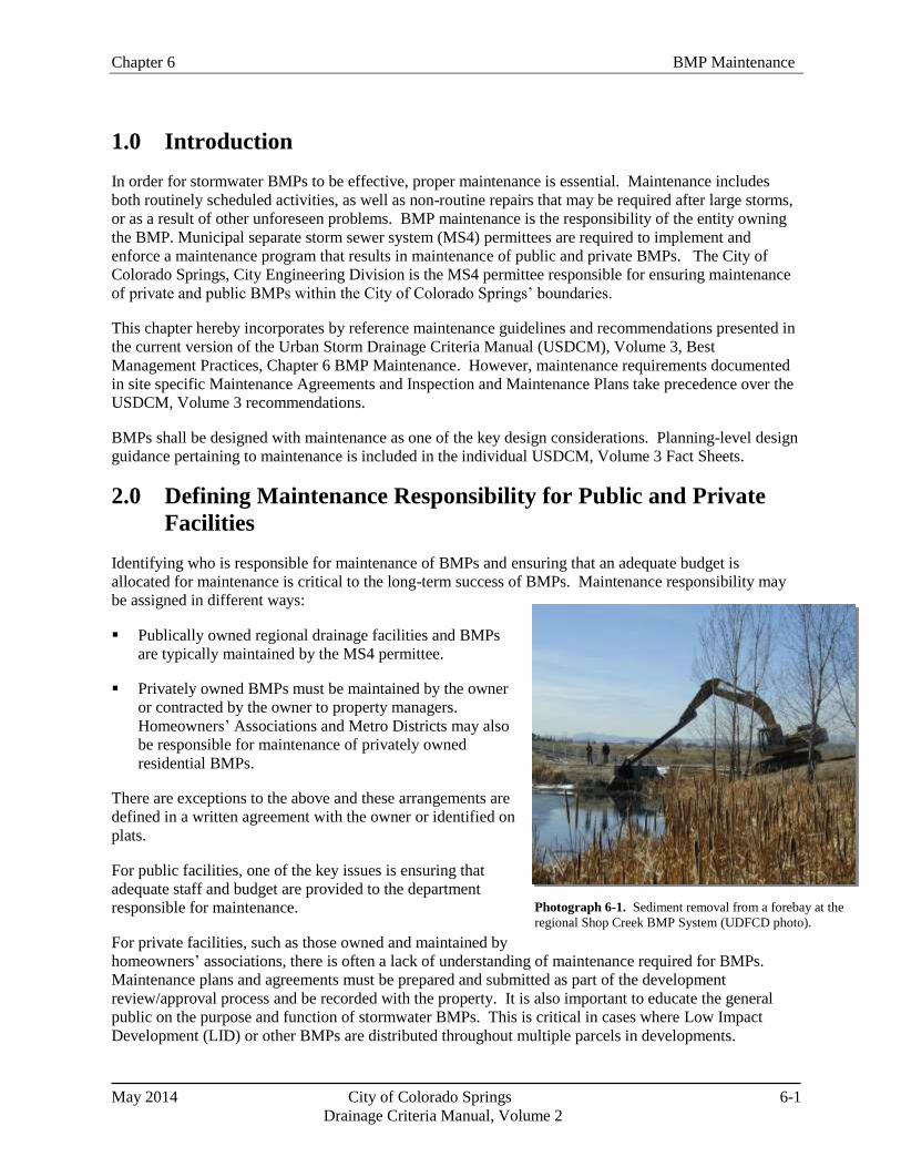
Chapter 6 BMP Maintenance
May 2014 City of Colorado Springs 6-1
Drainage Criteria Manual, Volume 2
Photograph 6-1. Sediment removal from a forebay at the
regional Shop Creek BMP System (UDFCD photo).
1.0 Introduction
In order for stormwater BMPs to be effective, proper maintenance is essential. Maintenance includes
both routinely scheduled activities, as well as non-routine repairs that may be required after large storms,
or as a result of other unforeseen problems. BMP maintenance is the responsibility of the entity owning
the BMP. Municipal separate storm sewer system (MS4) permittees are required to implement and
enforce a maintenance program that results in maintenance of public and private BMPs. The City of
Colorado Springs, City Engineering Division is the MS4 permittee responsible for ensuring maintenance
of private and public BMPs within the City of Colorado Springs’ boundaries.
This chapter hereby incorporates by reference maintenance guidelines and recommendations presented in
the current version of the Urban Storm Drainage Criteria Manual (USDCM), Volume 3, Best
Management Practices, Chapter 6 BMP Maintenance. However, maintenance requirements documented
in site specific Maintenance Agreements and Inspection and Maintenance Plans take precedence over the
USDCM, Volume 3 recommendations.
BMPs shall be designed with maintenance as one of the key design considerations. Planning-level design
guidance pertaining to maintenance is included in the individual USDCM, Volume 3 Fact Sheets.
2.0 Defining Maintenance Responsibility for Public and Private
Facilities
Identifying who is responsible for maintenance of BMPs and ensuring that an adequate budget is
allocated for maintenance is critical to the long-term success of BMPs. Maintenance responsibility may
be assigned in different ways:
Publically owned regional drainage facilities and BMPs
are typically maintained by the MS4 permittee.
Privately owned BMPs must be maintained by the owner
or contracted by the owner to property managers.
Homeowners’ Associations and Metro Districts may also
be responsible for maintenance of privately owned
residential BMPs.
There are exceptions to the above and these arrangements are
defined in a written agreement with the owner or identified on
plats.
For public facilities, one of the key issues is ensuring that
adequate staff and budget are provided to the department
responsible for maintenance.
For private facilities, such as those owned and maintained by
homeowners’ associations, there is often a lack of understanding of maintenance required for BMPs.
Maintenance plans and agreements must be prepared and submitted as part of the development
review/approval process and be recorded with the property. It is also important to educate the general
public on the purpose and function of stormwater BMPs. This is critical in cases where Low Impact
Development (LID) or other BMPs are distributed throughout multiple parcels in developments.
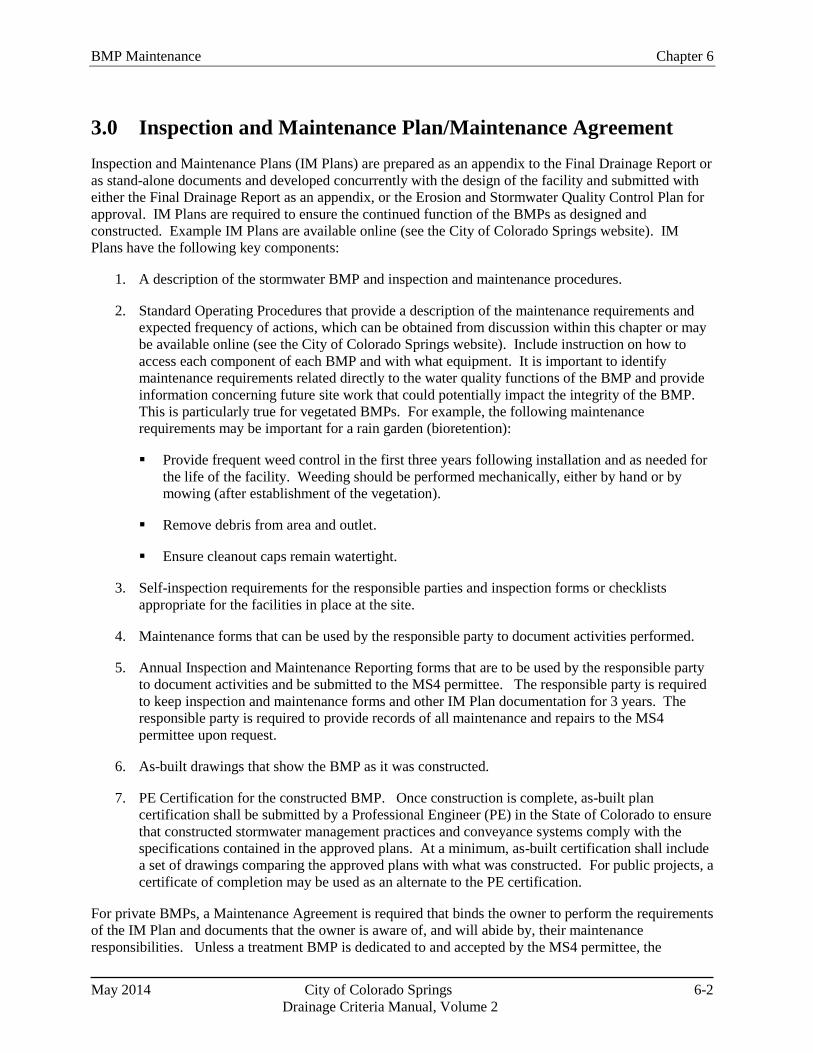
BMP Maintenance Chapter 6
May 2014 City of Colorado Springs 6-2
Drainage Criteria Manual, Volume 2
3.0 Inspection and Maintenance Plan/Maintenance Agreement
Inspection and Maintenance Plans (IM Plans) are prepared as an appendix to the Final Drainage Report or
as stand-alone documents and developed concurrently with the design of the facility and submitted with
either the Final Drainage Report as an appendix, or the Erosion and Stormwater Quality Control Plan for
approval. IM Plans are required to ensure the continued function of the BMPs as designed and
constructed. Example IM Plans are available online (see the City of Colorado Springs website). IM
Plans have the following key components:
1. A description of the stormwater BMP and inspection and maintenance procedures.
2. Standard Operating Procedures that provide a description of the maintenance requirements and
expected frequency of actions, which can be obtained from discussion within this chapter or may
be available online (see the City of Colorado Springs website). Include instruction on how to
access each component of each BMP and with what equipment. It is important to identify
maintenance requirements related directly to the water quality functions of the BMP and provide
information concerning future site work that could potentially impact the integrity of the BMP.
This is particularly true for vegetated BMPs. For example, the following maintenance
requirements may be important for a rain garden (bioretention):
Provide frequent weed control in the first three years following installation and as needed for
the life of the facility. Weeding should be performed mechanically, either by hand or by
mowing (after establishment of the vegetation).
Remove debris from area and outlet.
Ensure cleanout caps remain watertight.
3. Self-inspection requirements for the responsible parties and inspection forms or checklists
appropriate for the facilities in place at the site.
4. Maintenance forms that can be used by the responsible party to document activities performed.
5. Annual Inspection and Maintenance Reporting forms that are to be used by the responsible party
to document activities and be submitted to the MS4 permittee. The responsible party is required
to keep inspection and maintenance forms and other IM Plan documentation for 3 years. The
responsible party is required to provide records of all maintenance and repairs to the MS4
permittee upon request.
6. As-built drawings that show the BMP as it was constructed.
7. PE Certification for the constructed BMP. Once construction is complete, as-built plan
certification shall be submitted by a Professional Engineer (PE) in the State of Colorado to ensure
that constructed stormwater management practices and conveyance systems comply with the
specifications contained in the approved plans. At a minimum, as-built certification shall include
a set of drawings comparing the approved plans with what was constructed. For public projects, a
certificate of completion may be used as an alternate to the PE certification.
For private BMPs, a Maintenance Agreement is required that binds the owner to perform the requirements
of the IM Plan and documents that the owner is aware of, and will abide by, their maintenance
responsibilities. Unless a treatment BMP is dedicated to and accepted by the MS4 permittee, the
Chapter 6 BMP Maintenance
May 2014 City of Colorado Springs 6-3
Drainage Criteria Manual, Volume 2
responsible party must execute a Maintenance Agreement binding on all subsequent owners of land
served by the BMP. This agreement is a legally recorded document that acts as a property deed
restriction, and therefore, provides for long-term maintenance of treatment BMP. If portions of the land
are sold or otherwise transferred, legally binding arrangements shall be made to pass the inspection and
maintenance responsibility to the appropriate successors in title. The agreement provides that in the event
that maintenance or repair is neglected, or the treatment BMP becomes a danger to public health or safety,
the MS4 permittee has the authority to enter the property, perform the maintenance work required, and to
recover the costs from the owner.
The terms of the Maintenance Agreement shall provide for the MS4 permittee to enter the property at
reasonable times and in a reasonable manner for the purpose of inspection or maintenance and to confirm
the information in the annual inspection report submitted by the responsible party for maintenance. This
includes the right to enter a property when there is a reasonable basis to believe that inspection and
maintenance are not occurring or have not occurred and to enter when necessary to perform maintenance
at the responsible party’s expense. A template of the Maintenance Agreement is available online (City of
Colorado Springs website).
Erosion and Stormwater Quality Plan financial assurances will not be released until the above IM Plan
and Maintenance Agreement requirements have been met and the Maintenance Agreement is recorded.
4.0 Treatment BMP Inspections
Self-Inspections
The responsible party shall perform self-inspections of stormwater BMPs on a periodic basis in
accordance with the approved IM Plan, document the inspection(s), and submit an annual inspection and
maintenance report to the MS4 permittee (the City of Colorado Springs requires the reports be submitted
by May 31 of each year).
MS4 Permittee Inspections
The MS4 permittee will inspect private and public facilities once during the first year of operation and
then once every three (3) to five (5) years, depending on the type of BMP, maintenance history, and other
factors. Facilities will also be inspected by the MS4 permittee once a notice of violation has been issued
for not performing self-inspections. A Notification of Inspection Letter will be sent to the responsible
party to inform them that an inspection is scheduled. The letter will include the date of the inspection,
what to expect, and encourage the completion of routine maintenance actions by the responsible party
prior to the inspection.
5.0 Enforcement
In the event that the self-inspections are not submitted to the MS4 permittee per the required deadline, the
responsible party will be contacted and notified of the missed inspection. The responsible party must
complete the self-inspection and return it by mail to the MS4 permittee within the timeframe identified in
local code or otherwise a notice of violation (NOV) may be issued. Appeals of NOVs can be made using
the process identified in local code.
If deficiencies are noted during the MS4 permittee inspection, the responsible party will be notified of the
issues. The responsible party shall correct the deficiencies within the timeframe specified by local code.
A follow-up inspection will be conducted by the MS4 permittee to verify the repairs. If repairs are not
undertaken or are not found to be done properly, MS4 permittee staff or a hired contractor engaged by the

BMP Maintenance Chapter 6
May 2014 City of Colorado Springs 6-4
Drainage Criteria Manual, Volume 2
Additional References for Stormwater BMP Maintenance
City of Portland, Oregon. 2002. Maintaining Your Stormwater Management Facility: A Handbook
for Private Property Owners. Portland, OR: Bureau of Environmental Services.
http://www.portlandonline.com/Bes/index.cfm?a=54730&c=34980.
Low Impact Development Center. 2003. Low Impact Development Urban Design Tools.
http://www.lid-stormwater.net/bio_maintain.htm; http://www.lid-
stormwater.net/permpavers_maintain.htm
North Carolina State University Cooperative Extension. 2006. Bioretention Performance, Design,
Construction, and Maintenance.
http://www.bae.ncsu.edu/stormwater/PublicationFiles/Bioretention2006.pdf
Santa Clara Valley Urban Runoff Pollution Prevention Program Example BMP Inspection and
Maintenance Checklist. http://www.scvurppp-w2k.com/bmp_om_forms.htm
Southeast Metro Stormwater Authority (SEMSWA) Stormwater Management Facility Operation and
Maintenance (O&M) Manual. www.semswa.org
Watershed Management Institute. 1997. Operation, Maintenance and Management of Stormwater
Management Systems. Ingleside, MD: Watershed Management Institute.
MS4 permittee may enter upon the subject private property and complete the necessary maintenance at
the responsible party’s expense. Recovery of the costs by the MS4 permittee shall follow practices
permitted by local code.
If, during a MS4 permittee inspection, it is noted that the condition of a BMP presents an immediate
danger to the public health or safety due to an unsafe condition or improper maintenance, immediate
action can be taken by the MS4 permittee to protect the public and make the facility safe. Per local code,
any cost incurred by the MS4 permittee is at the responsible party’s expense.
6.0 References
Koski, T. and Skinner, V. 2003. Colorado State University Extension. Fact Sheet no.7.202, Lawn Care.
http://www.ext.colostate.edu/pubs/garden/07202.html.
Law, N.L., K. DiBlasi, and U. Ghosh. 2008. Deriving Reliable Pollutant Removal Rates for Municipal
Street Sweeping and Storm Drain Cleanout Programs in the Chesapeake Bay Basin. Center for
Watershed Protection. Prepared for U.S. EPA Chesapeake Bay Program Grant CB-973222-01:
Ellicott City, MD. www.cpw.org.
Wright Water Engineers, Inc., Wenk Associates, Muller Engineering Company, Inc., Matrix Design
Group, and Smith Environmental. 2004. City and County of Denver Water Quality Management
Plan. Denver, CO

7-i City of Colorado Springs May 2014
Drainage Criteria Manual, Volume 2
Chapter 7
Construction BMPs
Contents
1.0 Introduction ...................................................................................................................................... 1
2.0 Fundamental Erosion and Sediment Control Principles .............................................................. 2 2.1 Erosion ...................................................................................................................................................... 2 2.2 Sedimentation ............................................................................................................................................ 3 2.3 Effective Erosion and Sediment Control ................................................................................................... 3
3.0 Local and State Construction Stormwater Discharge Permits .................................................... 4 3.1 Preparing an Erosion and Stormwater Quality Control Plan ..................................................................... 5
3.1.1 Applicability ................................................................................................................................. 6 3.1.2 Basic Grading, Erosion and Stormwater Quality Requirements and General Prohibitions .......... 6 3.1.3 General Erosion and Stormwater Quality Control Plan Requirements ......................................... 7 3.1.4 Erosion and Stormwater Quality Control Elements ...................................................................... 7
3.2 Guarantee ................................................................................................................................................ 16 3.3 Erosion and Stormwater Quality Control Plan Implementation .............................................................. 17
3.3.1 Plan Acceptance .......................................................................................................................... 17 3.3.2 Installation of BMPs ................................................................................................................... 17
3.4 Modifications to the Erosion and Stormwater Quality Control Plan ....................................................... 17 3.4.1 City Requested ............................................................................................................................ 17 3.4.2 Owner/Contractor/Engineer Proposed ........................................................................................ 17
3.5 Erosion Control Inspections .................................................................................................................... 18 3.5.1 Types of Inspections ................................................................................................................... 18 3.5.2 Inspection Frequency .................................................................................................................. 20
3.6 Record Keeping ....................................................................................................................................... 21 3.7 Disposition of Temporary Measures ....................................................................................................... 21 3.8 Construction Enforcement Strategy ........................................................................................................ 22
3.8.1 Goal of Strategy .......................................................................................................................... 22 3.8.2 Policies ........................................................................................................................................ 22
4.0 Overview of Construction BMPs .................................................................................................. 25 4.1 Erosion Control Measures ....................................................................................................................... 27 4.2 Sediment Control Measures .................................................................................................................... 27 4.3 Site Management ..................................................................................................................................... 27 4.4 Materials Management ............................................................................................................................ 28 4.5 Use of Alternative, Proprietary or Innovative Sediment and Erosion Control (Temporary) BMPs ........ 28
5.0 BMP Selection and Planning ......................................................................................................... 29 5.1 Site Assessment ....................................................................................................................................... 29 5.2 Slope-Length and Runoff Considerations ............................................................................................... 30 5.3 Using the Revised Universal Soil Loss Equation .................................................................................... 31 5.4 BMP Functions ....................................................................................................................................... 32 5.5 Consistency with Other Plans ................................................................................................................. 32
5.5.1 Drainage Plans ............................................................................................................................ 33 5.5.2 Post Construction Stormwater Management ............................................................................... 33 5.5.3 Air Quality Plans ......................................................................................................................... 33
5.6 Integrating Site Conditions and BMPs into an Erosion and Stormwater Quality Control Plan .............. 33

7-ii City of Colorado Springs May 2014
Drainage Criteria Manual, Volume 2
6.0 Construction Dewatering ............................................................................................................... 34
7.0 Construction in Waterways ........................................................................................................... 35
8.0 Considerations for Linear Construction Projects ........................................................................ 37 8.1 General Considerations ........................................................................................................................... 37 8.2 Underground Utility Trenching Criteria ................................................................................................. 38
9.0 Construction BMP Fact Sheets ...................................................................................................... 39
10.0 Map Symbols ................................................................................................................................... 39
11.0 References ........................................................................................................................................ 39
Map Symbols
Figures
Figure 7-1. Components of Effective Stormwater Management at Construction Sites ............................... 1
Figure 7-2. Construction Stormwater Management ................................................................................... 25
Tables
Table 7-1. Comparison of State and Local Construction-Phase Stormwater Permits in Colorado .............. 5
Table 7-2. Possible Enforcement Options ................................................................................................. 23
Table 7-3. Overview of Construction BMPs .............................................................................................. 26

Chapter 7 Construction BMPs
7-1 City of Colorado Springs May 2014
Drainage Criteria Manual, Volume 2
Effective Stormwater
Management at Construction
Sites
Erosion Controls
(source controls)
Sediment Controls
(treatment)
Site Management
(procedures and schedules)
Materials Management
(source controls/reduce exposure)
1.0 Introduction
Effective management of stormwater runoff during construction activities is critical to the protection of
water resources. The Federal Clean Water Act and the Colorado Water Quality Control Act require
stormwater discharge permits during construction at development and redevelopment sites that disturb
one or more acres of land. Both erosion and sediment controls are necessary for effective construction
site management as well as effective material management and site management practices (Figure 7-1).
Protection of waterways from construction-related pollution is the ultimate objective of these practices.
This chapter provides an overview of erosion and sediment control principles and information on
construction best management practices (BMPs). Also provided are procedures and policies regarding
construction site inspection and enforcement. This chapter hereby incorporates by reference all criteria
presented in the current version of the Urban Storm Drainage Criteria Manual (USDCM), Volume 3, Best
Management Practices, Chapter 7 Construction BMPs for purposes of design and implementation.
Detailed descriptions, sizing and design criteria, and design procedures for these BMPs are provided in
the USDCM, V3 Construction BMP Fact Sheets.
Figure 7-1. Components of Effective Stormwater Management at Construction Sites
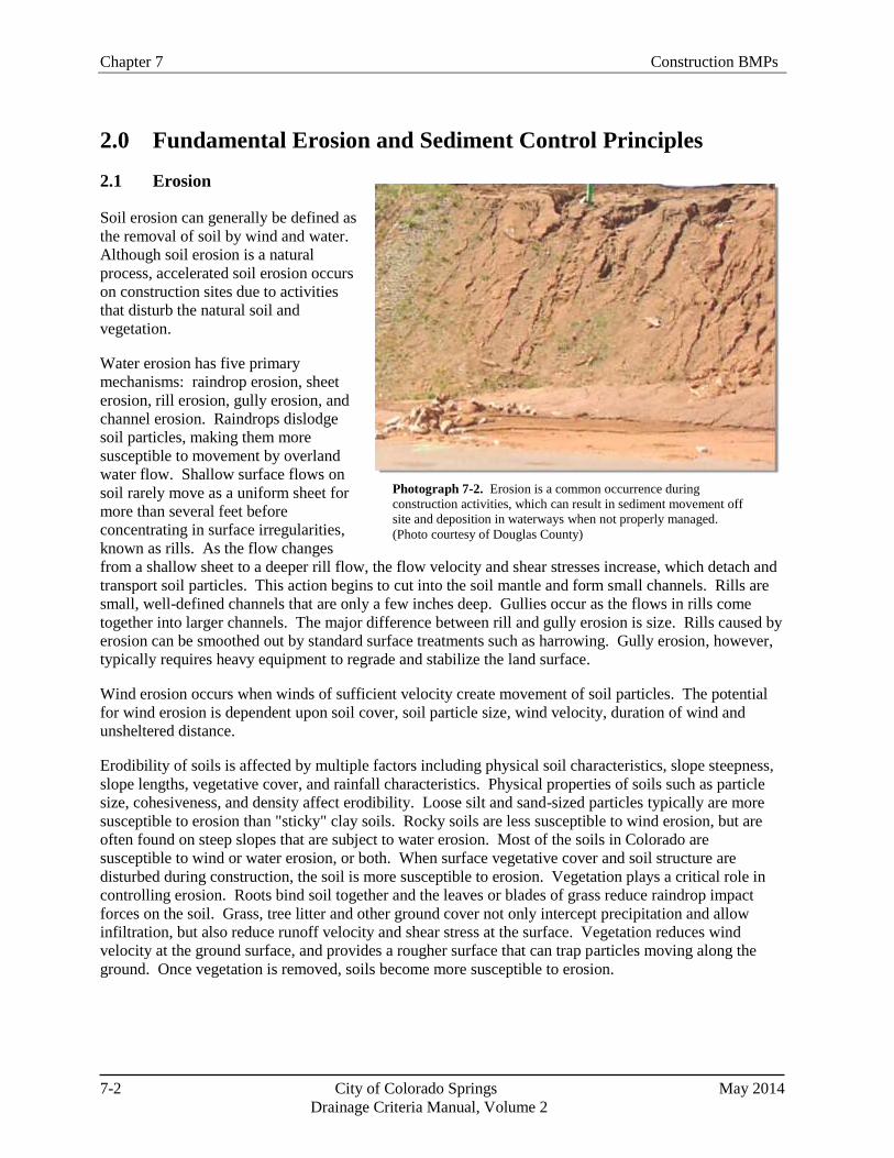
Chapter 7 Construction BMPs
7-2 City of Colorado Springs May 2014
Drainage Criteria Manual, Volume 2
Photograph 7-2. Erosion is a common occurrence during
construction activities, which can result in sediment movement off
site and deposition in waterways when not properly managed.
(Photo courtesy of Douglas County)
2.0 Fundamental Erosion and Sediment Control Principles
2.1 Erosion
Soil erosion can generally be defined as
the removal of soil by wind and water.
Although soil erosion is a natural
process, accelerated soil erosion occurs
on construction sites due to activities
that disturb the natural soil and
vegetation.
Water erosion has five primary
mechanisms: raindrop erosion, sheet
erosion, rill erosion, gully erosion, and
channel erosion. Raindrops dislodge
soil particles, making them more
susceptible to movement by overland
water flow. Shallow surface flows on
soil rarely move as a uniform sheet for
more than several feet before
concentrating in surface irregularities,
known as rills. As the flow changes
from a shallow sheet to a deeper rill flow, the flow velocity and shear stresses increase, which detach and
transport soil particles. This action begins to cut into the soil mantle and form small channels. Rills are
small, well-defined channels that are only a few inches deep. Gullies occur as the flows in rills come
together into larger channels. The major difference between rill and gully erosion is size. Rills caused by
erosion can be smoothed out by standard surface treatments such as harrowing. Gully erosion, however,
typically requires heavy equipment to regrade and stabilize the land surface.
Wind erosion occurs when winds of sufficient velocity create movement of soil particles. The potential
for wind erosion is dependent upon soil cover, soil particle size, wind velocity, duration of wind and
unsheltered distance.
Erodibility of soils is affected by multiple factors including physical soil characteristics, slope steepness,
slope lengths, vegetative cover, and rainfall characteristics. Physical properties of soils such as particle
size, cohesiveness, and density affect erodibility. Loose silt and sand-sized particles typically are more
susceptible to erosion than "sticky" clay soils. Rocky soils are less susceptible to wind erosion, but are
often found on steep slopes that are subject to water erosion. Most of the soils in Colorado are
susceptible to wind or water erosion, or both. When surface vegetative cover and soil structure are
disturbed during construction, the soil is more susceptible to erosion. Vegetation plays a critical role in
controlling erosion. Roots bind soil together and the leaves or blades of grass reduce raindrop impact
forces on the soil. Grass, tree litter and other ground cover not only intercept precipitation and allow
infiltration, but also reduce runoff velocity and shear stress at the surface. Vegetation reduces wind
velocity at the ground surface, and provides a rougher surface that can trap particles moving along the
ground. Once vegetation is removed, soils become more susceptible to erosion.
Chapter 7 Construction BMPs
7-3 City of Colorado Springs May 2014
Drainage Criteria Manual, Volume 2
State Construction Phase Permitting
Stormwater runoff controls from construction sites are mandated by the Federal Water Pollution
Control Act (Clean Water Act). In Colorado, the EPA has delegated authority to the Colorado
Department of Public Health and Environment (CDPHE). CDPHE, specifically the Water Quality
Control Division, issues stormwater and wastewater discharge permits under the Colorado
Discharge Permit System (CDPS) Regulation promulgated by the Water Quality Control
Commission.
2.2 Sedimentation
Sedimentation occurs when eroded soil transported in wind or water is deposited from its suspended state.
During a typical rainstorm in Colorado, runoff normally builds up rapidly to a peak and then diminishes.
Because the amount of sediment a watercourse can carry is dependent upon the velocity and volume of
runoff, sediment is eventually deposited as runoff decreases. The deposited sediments may be
resuspended when future runoff events occur. In this way, sediments are moved progressively
downstream in the waterway system.
2.3 Effective Erosion and Sediment Control
It is better to minimize erosion than to rely solely on sedimentation removal from construction site
runoff. Erosion control BMPs limit the amount and rate of erosion occurring on disturbed areas.
Sediment control BMPs attempt to capture the soil that has been eroded before it leaves the construction
site. Despite the use of both erosion control and sediment control BMPs, some amount of sediment will
remain in runoff leaving a construction site, but the use of a "treatment train" of practices can help to
minimize offsite transport of sediment. The last line of treatment such as inlet protection and sediment
basins should be viewed as "polishing" BMPs, as opposed to the only treatment on the site. USDCM, V3
BMP Fact Sheets provide design details and guidance for effective use of various erosion and sediment
control practices. BMPs should be combined and selected to meet these objectives:
Conduct land-disturbing activities in a manner that effectively reduces accelerated soil erosion and
reduces sediment movement and deposition off site.
Schedule construction activities to minimize the total amount of soil exposed at any given time.
Establish temporary or permanent cover on areas that have been disturbed as soon as practical after
grading is completed.
Design and construct temporary or permanent facilities to limit the flow of water to non-erosive
velocities for the conveyance of water around, through, or from the disturbed area.
Remove sediment caused by accelerated soil erosion from surface runoff water before it leaves the
site.
Stabilize disturbed areas with permanent vegetative cover and provide permanent stormwater quality
control measures for the post-construction condition.
Chapter 7 Construction BMPs
7-4 City of Colorado Springs May 2014
Drainage Criteria Manual, Volume 2
3.0 Local and State Construction Stormwater Discharge Permits
Development or redevelopment projects with one or more acres of potential disturbance are required to
obtain both local and state permits related to construction-phase stormwater discharges. The local permit
in Colorado Springs consists of an approved Erosion and Stormwater Quality Control Plan (see Section
3.1). The state permit is the CDPS General Permit for stormwater discharges associated with construction
activities. For both the local and state permit, the area of disturbance is the total area at the site where any
construction activity is expected to result in disturbance of the ground surface. This includes any activity
that could increase the rate of erosion, including but not limited to, clearing, grading, excavation, and
demolition activities, installation of new or improved haul roads and access roads, staging areas, vehicle
traffic areas, storage of materials, stockpiling of fill materials, and borrow areas and other construction
related activities. Construction does not include routine maintenance to maintain original line and grade,
hydraulic capacity, or original purpose of the facility.
The local MS4 permittee may require an Erosion and Stormwater Quality Control Plan for specific minor
land disturbing areas that are less than one acre. Within Colorado Springs, the City Engineer is
authorized by City Code to implement stormwater requirements and when warranted may require an
Erosion and Stormwater Quality Control Plan for specific minor land disturbing areas that are less than
one acre.
The Erosion and Stormwater Quality Control Plan has been structured to meet the requirements of the
CDPS General Permit for stormwater discharges associated with construction activities, in addition to
local requirements. It is anticipated that a single plan could meet both state and local requirements.
However, local requirements for the Erosion and Stormwater Quality Control Plan are more inclusive
than state requirements for the Stormwater Management Plan (SWMP). In addition, the developer should
note that compliance with one program does not fill the need to comply with the other. Also note that
although CDPHE does not require that the SWMP be submitted for approval, the Erosion and
Stormwater Quality Control Plan is required to be submitted and reviewed by the MS4 permittee and
must be approved prior to construction activities.
Local Erosion and Stormwater Quality Control Plans and state SWMPs are "living documents" that must
be updated and maintained as the phases of construction progress. Ideally, one master document could be
developed that is inclusive of both the local (Erosion and Stormwater Quality Control Plans) and state
(SWMPs ) requirements, as opposed to maintaining duplicate records. Compliance with all other local,
state and federal regulations is the responsibility of the owner, developer, contractor and engineer as it
relates to the development and implementation of the Erosion and Stormwater Quality Control Plan.
Common Plan of Development or Sale
US EPA defines a "larger common plan of development or sale" as a contiguous area where multiple
separate and distinct construction activities may be taking place at different times on different
schedules under one plan. For example, if a developer buys a 20-acre lot and builds roads, installs
pipes, and runs electricity with the intention of constructing homes or other structures sometime in
the future, this would be considered a larger common plan of development or sale. If the land is
parceled off or sold, and construction occurs on plots that are less than one acre by separate,
independent builders, this activity still would be subject to stormwater permitting requirements if the
smaller plots were included on the original site plan.
If the project is part of a common plan of development or sale, the disturbed area of the entire plan
must be used in determining permit requirements.

Chapter 7 Construction BMPs
7-5 City of Colorado Springs May 2014
Drainage Criteria Manual, Volume 2
Table 7-1. Comparison of State and Local Construction-Phase Stormwater Permits in Colorado
State Local Government
(programs vary, not inclusive)
Nomenclature Colorado Discharge Permit
System (CDPS) General
Permit for Stormwater
Discharges Associated with
Construction Activities
CDPS Individual Permit for
Stormwater Discharges
Associated with Construction
Activities
Erosion and Stormwater Quality Control
Plan
Triggers Area of potential disturbance
is greater than one acre
(This area includes
construction activities that are
part of a larger common plan
of development or sale.
Areas used for staging,
materials storage, temporary
construction site access, off-
site borrow areas and other
construction related activities
should also be included.)
State Construction Phase Stormwater Permit
required
Potential for erosion based on site
characteristics (i.e. hillside areas, steep
topography, highly erodible soils)
Contaminated soils on site
Sites within a designated 100-year
floodplain, stream overlay, and/or proximity
to active waterway
Required Items Application
Stormwater Management
Plan (SWMP). In other parts
of the country, this may be
referred to as a Stormwater
Pollution Prevention Plan
(SWPPP)
Annual Fee
Erosion and Stormwater Quality Control
Plan
Fee
3.1 Preparing an Erosion and Stormwater Quality Control Plan
An Erosion and Stormwater Quality Control Plan must be developed prior to construction and kept
current for the duration of construction. No clearing, grading, excavation, filling or other land
disturbing activities described in Section 3.1.1 shall be permitted until sign off and acceptance of the
Erosion and Stormwater Quality Control Plan is approved by the MS4 permittee. Reviews and
Chapter 7 Construction BMPs
7-6 City of Colorado Springs May 2014
Drainage Criteria Manual, Volume 2
approvals required by this manual for projects within the City of Colorado Springs will be completed
by the City Engineer and/or his or her designee.
Planning for erosion and stormwater quality control shall begin with the Preliminary Drainage Report
preparation, and shall include first-hand knowledge of the site by the engineer. Plan approval for the
Erosion and Stormwater Quality Control Plan shall be concurrent with review of the Preliminary/Final
Drainage Report and approval of the Grading Plan. The Erosion and Stormwater Quality Control Plan
may be combined with the Grading Plan if all information can be clearly presented. Plan signoff and
acceptance of both the Grading Plan and the Erosion and Stormwater Quality Control Plan, or a combined
plan, by the MS4 permittee constitutes a grading permit authorizing the approved land disturbance and
implementation of the approved erosion and stormwater quality control measures. The Erosion and
Stormwater Quality Control Plan should be consistent with the Final Drainage Report for a development
and other plans including Grading Plans, Development Plans, and utility facility plans.
3.1.1 Applicability
At a minimum, an Erosion and Stormwater Quality Control Plan is required in Colorado Springs
whenever a Grading Plan is required or when one (1) acre or more of land will be disturbed (disturbance
includes construction activities that are part of a larger common plan of development or sale).
Requirements for land disturbance in Hillside Overlay areas are incorporated into Section 504 of Part 5 of
Article 3 of Chapter 7 of the Colorado Springs City Code (Erosion and Stormwater Quality Control Plan
required with Development Plan, Development Plan amendment, plat or replat, whichever is applicable, in
designated hillside areas).
Typical activities for which an Erosion and Stormwater Quality Control Plan is generally not required are
designated as minor land disturbing activities and include:
1. Any project involving earth disturbing activity of less than 1 acre, unless deemed necessary by
the MS4 permittee and allowed by code.
2. Individual home landscaping, gardening, maintenance and repair work.
3. Agriculture and related activities.
The Erosion and Stormwater Quality Control Plan shall require the design, implementation and
maintenance of BMPs as set forth in this Manual and shall include the plan elements as set forth in this
Manual.
3.1.2 Basic Grading, Erosion and Stormwater Quality Requirements and General
Prohibitions
Grading, construction, and land development activities must control erosion and prevent the transport of
sediment onto adjacent properties, public rights-of-ways, streets, storm drainage facilities, channels or any
other public or private facilities. Land disturbance by any owner, developer, builder, contractor, or other
person shall comply with the general grading, erosion and stormwater quality requirements and general
prohibitions, including the 22 plan notes, as noted below. In many cases, this will require the design,
implementation and maintenance of BMPs as specified in the Manual, even if an Erosion and Stormwater
Quality Control Plan is not required. A typical example for this requirement would be a home building
contractor constructing one or more homes in an area on individual lots less than an acre and not part of a
larger common plan of development or sale.

Chapter 7 Construction BMPs
7-7 City of Colorado Springs May 2014
Drainage Criteria Manual, Volume 2
3.1.3 General Erosion and Stormwater Quality Control Plan Requirements
An Erosion and Stormwater Quality Control Plan shall communicate and satisfy the following:
o Identify all potential sources of pollution which may affect the quality of stormwater discharges
associated with construction activity;
o Describe the practices to be used to reduce the pollutants in stormwater discharges associated
with construction activity including the installation, implementation and maintenance
requirements; and
o Be prepared in accordance with good engineering, hydrologic, and pollution control practices and
be updated throughout construction and stabilization of the site.
Implement the provisions of the Erosion and Stormwater Quality Control Plan as written and updated,
from commencement of construction activity until final stabilization is complete. The Erosion and
Stormwater Quality Control Plan may require additions or other modifications once construction
commences, and documentation of all modifications and amendments is required. The contractor
shall maintain written records of all inspections, BMP maintenance, and communications with the
owner and/or engineer. This shall be kept at the construction site with the Erosion and Stormwater
Quality Control Plan.
The Erosion and Stormwater Quality Control Plan shall include additional discussion or plans for any
special requirements of the site. Special requirements include Spill Prevention Control and
Countermeasure (SPCC) plans under Section 311 of the Clean Water Act, or BMP programs
otherwise required by another CDPS permit.
3.1.4 Erosion and Stormwater Quality Control Elements
An Erosion and Stormwater Quality Control Plan shall be developed that consists of 1) a narrative
description of the construction project and 2) appropriate construction documents (plans/maps). The
Erosion and Stormwater Quality Control Plan shall consist of the most appropriate or best selection of
erosion control practices and sediment trapping facilities in conjunction with an appropriate schedule in
order to accomplish adequate control. Adequate erosion control measures shall be constructed prior to
land disturbing activities such that no adverse affect of site alternatives will impact the surrounding
properties. Particular attention shall be given to concentrated flows of water either to prevent their
occurrence or to provide appropriate conveyance devices to prevent erosion. Sediment trapping devices
shall be required at all points where sediment laden water might leave the site.
The Erosion and Stormwater Quality Control Plan shall include permanent structures for conveying and
treating storm runoff (when required per Chapter 4), how the site will be graded, final site stabilization,
temporary sediment control features including sediment basins and finally, stabilization of the site where
temporary features have been removed. Plans showing improvements or construction outside the
property line of the site will not be approved unless the plan is accompanied by an appropriate legal
easement, written acceptance by the adjacent property owner, or other acceptable form of correspondence
for the area in which such work is required.
The Erosion and Stormwater Quality Control shall include the following as a minimum. When some
sections are not applicable, include a statement to that effect.
Narrative Report: The narrative report must contain, at the minimum, the following:
Chapter 7 Construction BMPs
7-8 City of Colorado Springs May 2014
Drainage Criteria Manual, Volume 2
o Name, address, and telephone number of the owner/developer and, the name, address, and
telephone number of the professional engineer preparing the Erosion and Stormwater Quality
Control Plan.
o Subdivision Name – The name as it appears on the Final Subdivision Plat.
o Project description - A brief description of the nature and purpose of the land disturbing
activity, and project location.
o Existing site conditions - A description of the existing topography, vegetation, drainage, and
wetlands on the site to include estimate of percent existing vegetation cover. Also include
non-stormwater discharges (e.g. springs, landscape irrigation return flow, etc.)
o Receiving waters – name of receiving water and the size, type, and location of any outfalls.
Indicate if discharge to existing storm sewer system and name of ultimate receiving waters.
o Adjacent areas - A description of neighboring areas such as streams, residential areas, roads,
etc., which may be affected by the land disturbance.
o Soils - A brief description of the soils on the site including information on soil type and
character.
o Description of potential pollutants – sources such as vehicle fueling, chemical/ fertilizer
storage, construction dewatering, concrete washout area, etc.
o Soil Borings/Tests and Groundwater – Soil borings and tests, including groundwater analysis
and plan for safe discharge must be included if appropriate.
o Areas and Volume Statement - The total area of the site and the area of disturbance (e.g.
cleared, excavated, or graded) involved.
o Narrative description of appropriate controls and measures that will be implemented before
and during construction activities at the facility and address phased BMP implementation. It
shall clearly describe the relationship between the phases of construction the proposed
sequencing of major activities, BMP’s installed under each phase, and the implementation
and maintenance of control measures. For example, what BMP’s will be implemented during
each of the following stages of construction:
Clearing and grubbing necessary for perimeter controls
Initiation of perimeter controls
Remaining clearing and grubbing
Road grading
Drainage facility installation
Utilities installation
Vertical construction
Final grading
Stabilization
Removal of temporary control measures
The description of controls shall address the following areas:
Erosion and Sediment Control. This includes:

Chapter 7 Construction BMPs
7-9 City of Colorado Springs May 2014
Drainage Criteria Manual, Volume 2
1. Structural Practices – A description of structural site management practices
that will minimize erosion and sediment transport, including vehicle tracking
control.
2. Non-Structural Practices – A description of interim and permanent
stabilization practices, including site-specific scheduling of the
implementation of the practices.
Potential pollutant sources - The plan shall identify and describe those sources
determined to have the potential to contribute pollutants to stormwater discharges,
and how the sources will be controlled through BMP selection and implementation.
Materials Handling, and Spill Prevention and Response. The plan shall identify any
procedures of materials handled at the site that could contribute pollutants to runoff.
Areas where potential spills can occur shall have spill prevention and response
procedures identified. Materials of interest could include: exposed storage of
building materials; paints and solvents; fertilizers or chemicals; waste material; and
equipment maintenance or fueling procedures.
Waste Management and Disposal, including Concrete Washout. The plan shall
clearly describe and locate the practices implemented at the site to control stormwater
pollution from all construction site wastes (liquid and solid), including concrete
washout activities. The practices used for concrete washout must ensure that these
activities do not result in the contribution of pollutants associated with the washing
activity to stormwater runoff. The plan shall clearly describe and locate the practices
used that will ensure that no washout water from concrete washout activities is
discharged from the site as surface runoff or to surface waters.
o Erosion and Stormwater Quality Control Plan Administrator - Identify a specific
individual(s), position, or title that is responsible for developing, implementing, maintaining,
and revising the Erosion and Stormwater Quality Control Plan. This designated individual(s)
or position(s) should address all aspects of the facility's Erosion and Stormwater Quality
Control Plan. If this is unknown with plan submittal, then leave a blank for this information
to be filled in once a contractor is selected. This individual(s) must be a registered PE in
Colorado or certified in a City approved erosion control inspection class. The City can be
contacted for approved classes.
o Timing schedule - Indicate the anticipated starting and completion time periods of the site
grading
o Permanent stabilization - A description, including specifications, of how the site will be
stabilized after construction is completed and any planned practices to control pollutants in
stormwater discharges that will occur after construction operations have been completed at
the site.
o Owner inspections and maintenance of construction BMP’s – A description of procedures
and a schedule of regular inspections during construction for vegetation, erosion and
sediment control measure repair, and other protective measures identified in the plan. A
detailed description of the maintenance program for sediment control facilities, including
inspection programs, vegetative establishment on exposed soils, method and frequency of
removal and disposal of waste materials from control facilities, and disposition of temporary
structural measures shall be included.

Chapter 7 Construction BMPs
7-10 City of Colorado Springs May 2014
Drainage Criteria Manual, Volume 2
o Groundwater and Stormwater Dewatering - These activities often require a separate state
dewatering permit that includes sampling of processed waters. However, in some cases,
these activities can be conducted without a separate state permit when processed water is not
discharged from the site as surface runoff or discharged into surface waters. The Erosion and
Stormwater Quality Control Plan shall describe how these waters will be used (i.e., land
application, infiltration, evaporation) and how the specific practices at the site will ensure that
these waters are not discharged via runoff.
Construction Plan/Site Map. The information listed below shall be included on one or multiple
legible site maps. The map shall use one of the following scales; 1”=20’ up to 1”=100’. The scale
selected must be suitable for practical use and readability. The contour interval for these plans shall
be 2 feet or closer.
o General vicinity map Showing relationship of the site to existing and planned roadways,
jurisdictional boundaries, major creeks, and streams.
o Subdivision name – The name as it appears on the Final Subdivision Plat.
o General Notes - See Plan Notes (see below)
o Cost Estimate of the temporary and permanent BMP’s including installation and maintenance
until final stabilization is achieved. A unit price list may be obtained from the City
Engineering office.
o Signature blocks - See Signature Block discussion below.
o North Arrow and Scale
o Property lines for the site on which the work will be performed.
o Areas of soil disturbance – total area of the site where any construction activity is expected to
result in disturbance of the ground surface.
o Cut and fill demarcation line
o Construction site boundaries – area of soil disturbance and staging areas.
o Existing topography at one or two foot contour intervals. The map should extend a minimum
of 50-feet beyond the property line or beyond the project’s soil disturbance limits, whichever
is larger.
o Proposed topography at one or two foot contour intervals. The map should show elevations
and extent and the slope of all proposed grading, including building site and driveway grades.
o Location of any proposed features and structures on this site.
o Location of all natural features which affect the site specific water quality or adjacent to the
site. To include wetlands, highly permeable soils, etc…
o Adjacent existing and proposed development affected by the construction
o Location of soil stockpiles - Areas designated for topsoil and subsoil storage.

Chapter 7 Construction BMPs
7-11 City of Colorado Springs May 2014
Drainage Criteria Manual, Volume 2
o Location of critical erosion areas – areas of highly erodible soils.
o Location of existing or proposed water courses – to include, but not limited to, groundwater
springs, streams, wetland, or other surface waters.
o Location and plans for all drainage features, paved areas, retaining walls, cribbing, and
plantings constructed as part of this proposed site.
o Location of temporary or permanent soil erosion and sediment control measures or other
features to be constructed in connection with, or as a part of, the proposed work.
o Depict all erosion control measures using the standard map symbols given in the Drainage
Criteria Manual,Volume 2. The symbols should be bold and tend to “stand out” on the plans.
o Location and description of any potential natural pollutant sources –practices implemented at
the site to control stormwater pollution from the dewatering of uncontaminated groundwater
or stormwater from excavations, wells, etc….
o Location of storage equipment maintenance and temporary disposal areas – for example,
areas designated for equipment, building materials, fuel storage, fueling, lubricants, chemical,
concrete truck washout, and all temporary construction waste storage.
o Vegetation – existing vegetation to remain and proposed seeding areas
o Location of any dedicated asphalt or concrete batch plants
o Boundaries of the 100-yr floodplain
o Is the site in the City’s Streamside Zone? - show Streamside zone boundaries
o Soil Types
o Emergency overflow swales - located at all sump inlet locations and be sized for the 100-yr
storm event.
o Flow route – flow through and overflow of permanent BMP’s and temporary sediment
basins.
o Existing utility locations and easements - grading over existing utilities or within dedicated
easements is restricted
o Detail Drawings of Temporary BMP’s including installation and maintenance. Provide
enough detail for each BMP to ensure proper installation and maintenance.
o Detail Drawings of Permanent BMP’s - provide enough site specific detail for each BMP to
ensure proper installation/construction.
Plan Notes. The below twenty two (22) plan notes shall be included on the Erosion and Stormwater
Quality Control Plan. Per the Engineering Criteria Manual, the summary 8 notes found in that
document may be listed on the plan and reference the 22 notes.
Chapter 7 Construction BMPs
7-12 City of Colorado Springs May 2014
Drainage Criteria Manual, Volume 2
1. Stormwater discharges from construction sites shall not cause or threaten to cause pollution,
contamination, or degradation of State Waters.
2. Concrete wash water shall not be discharged to or allowed to runoff to the Municipal
Separate Storm Sewer System (MS4).
3. Building, construction, excavation, or other waste materials shall not be temporarily placed
or stored in the street, alley, or other public way, unless in accordance with an approved
Traffic Control Plan. BMPs may be required by the MS4 permittee if deemed necessary,
based on specific conditions and circumstances (e.g., estimated time of exposure, season of
the year, etc.).
4. Vehicle tracking of soils off-site shall be minimized.
5. All wastes composed of building materials must be removed from the construction site for
disposal in accordance with local and state regulatory requirements. No building material
wastes or unused building materials shall be buried, dumped, or discharged at the site.
6. No chemicals are to be added to the discharge unless permission for the use of a specific
chemical is granted by the state. In granting the use of such chemicals, special conditions
and monitoring may be required.
7. Bulk storage structures for petroleum products and other chemicals shall have secondary
containment or equivalent adequate protection so as to contain all spills and prevent any
spilled material from entering the MS4, including any surface or subsurface storm drainage
system or facilities.
8. All persons engaged in earth disturbance shall implement and maintain acceptable soil
erosion and sediment control measures including BMPs in conformance with the erosion
control technical standards of the Drainage Criteria Manual, Volume 2 and in accordance
with the approved Erosion and Stormwater Quality Control Plan approved by the MS4
permittee, if required.
9. All temporary erosion control facilities including BMPs and all permanent facilities intended
to control erosion of any earth disturbance operations, shall be installed as defined in the
approved Erosion and Stormwater Quality Control Plan and the Drainage Criteria Manual,
Volume 2 and maintained throughout the duration of the earth disturbance operation. The
installation of the first level of temporary erosion control facilities and BMPs shall be
installed and inspected prior to any earth disturbance operations taking place.
10. Any earth disturbance shall be conducted in such a manner so as to effectively reduce
accelerated soil erosion and resulting sedimentation.
11. All earth disturbances shall be designed, constructed, and completed in such a manner so
that the exposed area of any disturbed land shall be limited to the shortest practical period of
time.
12. All work and earth disturbance shall be done in a manner that minimizes pollution of any on-
site or off-site waters, including wetlands.
13. Suspended sediment caused by accelerated soil erosion shall be minimized in runoff water
before it leaves the site of the earth disturbance.
Chapter 7 Construction BMPs
7-13 City of Colorado Springs May 2014
Drainage Criteria Manual, Volume 2
14. Any temporary or permanent facility designed and constructed for the conveyance of
stormwater around, through, or from the earth disturbance area shall be designed to limit the
discharge to a non-erosive velocity.
15. Temporary soil erosion control facilities shall be removed and earth disturbance areas graded
and stabilized with permanent soil erosion control measures pursuant to the standards and
specifications prescribed in the Drainage Criteria Manual, Volume 2, and in accordance with
the permanent erosion control features shown on the approved Erosion and Stormwater
Quality Control Plans, if required.
16. Soil erosion control measures for all slopes, channels, ditches, or any disturbed land area
shall be completed within twenty-one (21) calendar days after final grading, or final earth
disturbance, has been completed. Disturbed areas and stockpiles which are not at final grade
but will remain dormant for longer than 30 days shall also be mulched within 21 days after
interim grading. An area that is going to remain in an interim state for more than 60 days
shall also be seeded. On a case-by-case basis, the MS4 permittee may allow another
appropriate BMP to be in place that prevents sediment from leaving the site. All temporary
soil erosion control measures and BMPs shall be maintained until permanent soil erosion
control measures are implemented.
17. No person shall cause, permit, or contribute to the discharge into the municipal separate
storm sewer pollutants that could cause the MS4 permittee to be in violation of its Colorado
Discharge Permit System MS4 Permit.
18. The owner, site developer, contractor, and/or their authorized agents shall be responsible for
the removal of all construction debris, dirt, trash, rock, sediment, and sand that may
accumulate in the storm sewer or other drainage conveyance system and stormwater
appurtenances as a result of site development.
19. No person shall cause the impediment of stormwater flow in the flow line of the curb and
gutter, including the temporary or permanent ramping with materials for vehicle access.
20. Individuals shall comply with the “Colorado Water Quality Control Act” (Title 25, Article 8,
CRS), and the “Clean Water Act” (33 USC 1344), regulations promulgated, certifications or
permits issued, in addition to the requirements included in the Drainage Criteria Manual,
Volume 2. In the event of conflicts between these requirements and water quality control
laws, rules, or regulations of other Federal or State agencies, the more restrictive laws, rules,
or regulations shall apply.
21. The quantity of materials stored on the project site shall be limited, as much as practical, to
that quantity required to perform the work in an orderly sequence. All materials stored on-
site shall be stored in a neat, orderly manner, in their original containers, with original
manufacturer’s labels. Materials shall not be stored in a location where they may be carried
by stormwater runoff into the MS4 at any time.
22. Spill prevention and containment measures shall be used at storage, and equipment fueling
and servicing areas to prevent pollution from discharging to the MS4. All spills shall be
cleaned up immediately after discovery, or contained until appropriate cleanup methods can
be employed. Manufacturer’s recommended methods for spill cleanup shall be followed,
along with proper disposal methods.
Chapter 7 Construction BMPs
7-14 City of Colorado Springs May 2014
Drainage Criteria Manual, Volume 2
Final Stabilization and Long-Term Stormwater Management
o The Erosion and Stormwater Quality Control Plan narrative report should describe the practices
used to achieve final stabilization of all disturbed areas at the site and any planned practices to
control pollutants in stormwater discharges that will occur after construction operations have been
completed at the site.
o Final stabilization practices for obtaining a vegetative cover should include, as appropriate: seed
mix selection and application methods; soil preparation and amendments; soil stabilization
practices (e.g., crimped straw, hydro mulch or rolled erosion control products); and appropriate
sediment control BMPs as needed until final stabilization is achieved; etc.
o Final stabilization is reached when all ground surface disturbing activities at the site have been
completed, and uniform vegetative cover has been established with an individual plant density of
at least 70 percent of pre-disturbance levels plant density, or equivalent permanent, physical
erosion reduction methods have been employed, as determined by the MS4 permittee. Re-
seeding alone does not qualify. Documentation of pre-disturbance conditions assists in making
this determination. The developer/owner will be responsible for providing documentation to
make this comparison. Upon good cause, the MS4 permittee may amend the final stabilization
criteria for specific operations.
Inspection and Maintenance
The Erosion and Stormwater Quality Control Plan narrative report shall describe the self inspection
and maintenance procedures implemented at the site to maintain all erosion and sediment control
practices and other protective practices identified in the Erosion and Stormwater Quality Control Plan
in good and effective operating condition. Proactive maintenance is fundamental to effective BMP
performance. Rather than maintaining the BMP in a reactive manner following failure, provide
proactive maintenance that may help to reduce the likelihood of failure. The types and frequencies of
maintenance are BMP-specific. The USDCM, V3 BMP Fact Sheets describe the maintenance needs
for each BMP, with some BMP types requiring more attention.
All temporary and permanent erosion and sediment control practices shall be maintained and repaired
by the owner during the construction phase as needed to assure continued performance of their
intended function. All facilities must be inspected and then cleaned, repaired or replaced if necessary,
following each precipitation or snowmelt event that results in runoff.
Plan Preparation by a Colorado Professional Engineer
The State Board of Licensure for Architects, Professional Engineers, and Professional Land
Surveyors (Board) does not consider erosion and sediment control plans that do not contain
engineering information or engineering features as the practice of engineering. However, grading
and erosion control plans are considered the practice of engineering. Grading, Erosion and
Stormwater Quality Control Plan (a combined plan) being submitted for approval must be prepared
by or under the direction of a Colorado Professional Engineer’s (P.E.) and include the P.E.’s number
and signature and the required owner’s compliance statement and signature. In addition, Erosion and
Stormwater Quality Control Plans that include permanent, treatment best management practices
must also be submitted for approval must be prepared by or under the direction of a Colorado P.E..
Prints of the approved plan must bear the professional seal of the P.E. in accordance with City Code
Section 7.7.1504 and State Law.

Chapter 7 Construction BMPs
7-15 City of Colorado Springs May 2014
Drainage Criteria Manual, Volume 2
Signature Blocks
Engineer’s Statement - The following statement is required on all plans along with the Engineer’s
signature: “This Erosion and Stormwater Quality Control/Grading Plan was prepared under my
direction and supervision and is correct to the best of my knowledge and belief. If such work is
performed in accordance with the grading and erosion control plan, the work will not become a
hazard to life and limb, endanger property, or adversely affect the safety, use, or stability of a public
way, drainage channel, or other property.”
Developer’s/Owner’s Statement - The following statement is required on all Erosion and Stormwater
Quality Control/Grading Plans prepared for new development and redevelopment (non-public
project) along with the Developer’s/Owner’s signature: “The owner will comply with the
requirements of the Erosion and Stormwater Quality Control Plan including temporary BMP
inspection requirements and final stabilization requirements. I acknowledge the responsibility to
determine whether the construction activities on these plans require Colorado Discharge Permit
System (CDPS) permitting for Stormwater discharges associated with Construction Activity.”
City Engineering Review Statement - The following statement is required on all plans along with the
City’s Review Engineer’s signature: “This grading plan is filed in accordance with section 7.7.1503
(enacted as ord. 82-56) of the code of the City of Colorado Springs, 2001, as amended. Erosion
control is reviewed in accordance with the Drainage Criteria Manual, Vol. I (2012) and Vol. II
(2012), latest revisions”
Public Project Contractor Statement - The following statement is required on all Erosion and
Stormwater Quality Control/Grading Plans prepared by Contractors for Public Projects along with the
Public Project Contractor’s signature: “The Public Project Contractor will comply with the
requirements of the Erosion and Stormwater Quality Control Plan including temporary BMP
inspection requirements and final stabilization requirements. I acknowledge the responsibility to
determine whether the construction activities on these plans require Colorado Discharge Permit
System (CDPS) permitting for Stormwater discharges associated with Construction Activity.”
Transfer of Plan/Permit
The Erosion and Stormwater Quality Control permit (approved Erosion and Stormwater Quality
Control Plan) may be transferred from one party to another upon submittal of a transfer form
(available from the MS4 permittee). Transfer forms must be approved by the MS4 permittee prior to
the transfer taking effect. Both parties must consent to the transfer with the new responsible party
accepting the plan responsibilities and liabilities. The transfer may also require authorization by the
Engineer that developed and signed the Erosion and Stormwater Quality Control Plan.
Financial assurances (see Section 3.2) must be in place for the Erosion and Stormwater Quality
Control Plan before and after the permit transfer.
Sale of Residence to Homeowner
For residential construction only and similar to state requirements, when a residential lot has been
conveyed to a homeowner and all criteria in paragraphs a through e, below, are met, coverage under
the approved Erosion and Stormwater Quality Control Plan and permit is no longer required. At such
time, the builder is no longer responsible for meeting the terms and conditions of the plan for the
conveyed lot.
a) The lot has been sold to the homeowner(s) for private residential use;

Chapter 7 Construction BMPs
7-16 City of Colorado Springs May 2014
Drainage Criteria Manual, Volume 2
b) the lot is less than one acre of disturbed area;
c) all construction activity conducted by the builder on the lot is completed;
d) a certificate of occupancy (or equivalent) has been awarded to the homeowner; and
e) the Erosion and Stormwater Quality Control Plan has been amended to indicate the lot is
no longer covered by the approved plan.
Lots not meeting all of the above criteria require continued plan and permit coverage. However, the
plan and permit may be transferred to a new owner or operator.
Plan Expiration/Resubmittal Requirements
Erosion and Stormwater Quality Control Plans expire if site construction or land disturbance has not
commenced within twelve (12) months of plan approval. The plans must then be resubmitted for re-
approval. Previously approved plans must also be resubmitted for re-approval when any of the
following occur:
o Change in ownership of the property to be disturbed, including ownership by a bank through
foreclosure proceedings, excluding if the plan/permit has been transferred,
o Major BMP changes (see Section 3.4),
o Major development design changes to the site, or
o Major grading design revisions to the site.
3.2 Guarantee
A financial assurance of all temporary and permanent treatment BMPs included on the Erosion and
Stormwater Quality Control Plan shall be provided, subject to current policies, which exclude enterprises
of the City of Colorado Springs from this requirement. The Erosion and Stormwater Quality Control Plan
must also include a cost estimate for any temporary and permanent erosion control measures to include,
but not limited to, silt fence, sediment basins, vehicle tracking controls, check dam, erosion control
blanket, inlet protection, permanent treatment water quality ponds, porous pavement surfaces, re-
vegetation, and maintenance costs. The plan must separately delineate the financial assurance for the
permanent BMPs and the temporary BMPs. Financial assurances shall be posted by the owner/developer
for all erosion control measures prior to approval of any land disturbance activities. The owner/ developer
shall provide the financial assurances prior to plan sign off, and will be released when the disturbed areas
are stabilized, treatment BMPs constructed, inspection and maintenance requirements for treatment BMPs
met, or established to the satisfaction of the MS4 permittee in accordance with the Drainage Criteria
Manual, Volume 2 and a written letter requesting release has been submitted to the MS4 permittee. The
owner/developer may also make arrangements with the builder to require the builder to post financial
assurances so that the owner/developers assurances can be released. Financial assurances will not be
released to the owner/developer until the builder as posted financial assurances.
Enforcement actions may require the use of the financial assurance currently on file for the project site
(regardless of ownership) to address non-compliance issues. If the enforcement process results in the use
of the financial assurances and work is contracted by the MS4 permittee to address the non-compliance
issues, the MS4 permittee or the MS4 permittee’s contractor will update the Erosion and Stormwater
Chapter 7 Construction BMPs
7-17 City of Colorado Springs May 2014
Drainage Criteria Manual, Volume 2
Quality Control Plans to show activities performed with the financial assurance. The owner/developer
must update and resubmit the Erosion and Stormwater Quality Control Plan and repost assurances prior to
continuing work on the site.
3.3 Erosion and Stormwater Quality Control Plan Implementation
3.3.1 Plan Acceptance
No clearing, grading, excavation, filling, or other land-disturbing activities shall be permitted until signoff
and acceptance of the Grading Plan and Erosion and Stormwater Quality Control Plan (or the combined
plan) is received from the MS4 permittee.
3.3.2 Installation of BMPs
Once signoff and acceptance is received, the approved erosion and sediment control measures must be
installed before land-disturbing activities are initiated so that no adverse effect of site alteration will
impact surrounding property. These measures shall apply to all features of the construction site including,
but not limited to, street and utility installations, as well as to the protection of individual lots. During all
phases of construction, it shall be the responsibility of those initiating such land disturbing activities to
maintain all erosion control features in a functional manner.
3.4 Modifications to the Erosion and Stormwater Quality Control Plan
3.4.1 City Requested
Additional information may be required for projects where soil erosion, sedimentation, or stormwater
quality control problems will not be adequately handled by the submitted plan. Such data may include,
but not be limited to, other engineering studies, computations, schedules, and supportive data such as
product design information and specifications.
It shall be understood that additional or revised BMPs may be required should construction site
observation indicate the BMPs are not adequately controlling erosion, sedimentation or stormwater runoff
from equipment fueling/maintenance and materials storage areas.
3.4.2 Owner/Contractor/Engineer Proposed
Minor field modifications to erosion and sediment control and treatment BMPs may be approved by the
MS4 permittee inspector. Such modifications would include minor adjustments to BMP field locations or
a change to a similar erosion and sediment control BMP to better correspond to actual site conditions or to
improve BMP performance. No formal written approval will be required, except the inspector shall initial
the changes on the updated Erosion and Stormwater Quality Control Plan (on-site copy).
All other requested major modifications shall be in writing and submitted to the MS4 permittee.
Examples of major modifications to temporary BMPs that require re-submittal include change to pipe
sizes or pipe strength (could be used with temporary stream crossings) and changes to peak discharges or
hydraulic calculations. Changes of temporary BMP types or locations on the site are not considered
major modifications.
Examples of major modifications to permanent treatment BMPs include change in BMP type, change to
volume of BMP, change to drain times (e.g., changes to size or number of orifices), additional hardening,

Chapter 7 Construction BMPs
7-18 City of Colorado Springs May 2014
Drainage Criteria Manual, Volume 2
elimination of any significant features, change in location or drainage patterns, and change in media.
Major modifications, including revised calculations and plans, shall be submitted for re-approval.
3.5 Erosion Control Inspections
Routine and post-storm inspections of BMPs are essential to identify maintenance necessary for the
BMPs to remain in effective operating conditions. Inspections are performed by MS4 permittee
inspectors and also required of the owner or owner’s representative. In Colorado Springs, the City
Engineering Inspections’ staff performs site inspections and also provides educational information to the
owners/owner’s representatives, developers, and contractors on minimizing the stormwater quality
impacts from site operations. Ultimately, it is the responsibility of the owner to take all necessary
measures to ensure that the site is in compliance with local and state requirements and the Erosion and
Stormwater Quality Control Plan.
The MS4 permittee’s review of an Erosion and Stormwater Quality Control Plan is the first step in
determining the type of inspections needed and the relative priority of the site for inspections.
3.5.1 Types of Inspections
The following are inspections performed at construction sites within the City of Colorado Springs. The
City shall have the right to enter the construction site at any time to determine if the site is in compliance
with the plan. Not all inspection types will be performed at all sites.
Self-Inspections
The owner or his representative conducts self-inspections. The purpose of these inspections is to ensure
that all BMPs are installed according to approved plans and that the BMPs are being properly maintained.
The person performing the inspections must be a registered professional engineer in Colorado, a certified
erosion control specialist, or certified in a City-approved inspection training program.
The owner or his representative will record the results of the self-inspections by completing a copy of the
City of Colorado Springs Inspection Checklist (Appendix C). Completed Inspection Checklists will be
submitted electronically to the assigned City Engineering inspector within 5 business days of the self-
inspection. The self-inspections must also be kept on-site.
Initial Inspections
Initial inspections are to confirm that the approved plan is being implemented. The City Engineering
Inspector must be contacted by the owner/owner’s representative/contractor at least 48 hours prior to
scheduling the Initial Inspection. It is expected that at the time of the initial inspection, the first level of
BMPs will have been implemented according to those plans and that no land disturbing activity will have
occurred prior to the Initial Inspection. This inspection also serves to establish contact between inspectors
and the site personnel responsible for implementing the approved plans. This is especially important for
those sites that have a long construction period or the potential to have a significant impact. Initial
inspections are only conducted on sites that require an Erosion and Stormwater Quality Control Permit.
These inspections are documented on the Inspection Checklist.
Compliance Inspections
Compliance inspections are performed by City Engineering Inspectors. The inspector verifies that the
latest self-inspection report is accurate and that BMPs are functioning according to design and only
Chapter 7 Construction BMPs
7-19 City of Colorado Springs May 2014
Drainage Criteria Manual, Volume 2
allowable discharges are occurring. The inspector also verifies that the Erosion and Stormwater Quality
Control Plan is updated to reflect current BMP activity. Compliance inspections may also occur during or
immediately after a precipitation event. Compliance inspections are only conducted for sites that require
an Erosion and Stormwater Quality Control Permit. The City uses the Inspection Checklist to document
these inspections.
Reconnaissance Inspections
Reconnaissance inspections are conducted by a City Engineering Inspector for the general purpose of
determining conditions at the site, particularly if the site has contributed sediment to drainageways or
other drainage facilities, or if material has runoff the site. These inspections are generally performed from
off-site on adjacent streets or property, and may occur during or immediately after a significant
precipitation event. This type of inspection is normally aimed at potential problem sites or sites that
typically do not require an Erosion and Stormwater Quality Control Permit. The results of a
reconnaissance inspection could require a site that previously was not required to develop an Erosion and
Stormwater Quality Control Plan to develop one. The inspection will be documented using the Inspection
Checklist.
Complaint Response Inspections
These City inspections will occur in response to either a citizen complaint or a complaint from another
City agency. The inspector will inform the contractor and owner/owner’s representative of the complaint,
determine the validity of the complaint, and if necessary, advise on the necessary repair, maintenance or
cleanup. The inspector may also require the implementation of specific measures or additional BMPs to
prevent the recurrence of the problems that gave rise to the complaint. All construction sites are subject
to complaint response inspections. The inspection will be documented using the Inspection Checklist.
Follow-up Inspections
Follow-up inspections are conducted to ensure that measures or requirements from a previous City
inspection have been performed or complied with. These requirements may involve the cleanup of a
discharge, implementing additional or revised BMPs, repairing, reinstalling, or maintaining damaged or
non-functioning BMPs. All construction sites are subject to follow-up inspections. The inspection will
be documented using the Inspection Checklist.
Final Inspections
A final inspection of the site is conducted by the City Engineering Inspector to determine overall compliance with the Erosion and Stormwater Quality Control Plan, to determine if measures
have been taken to stabilize the site prior to final approval, and prior to release of any financial
assurances. The City Engineering Inspector must be contacted by the owner/owner’s
representative/contractor at least 48 hours prior to scheduling the Final Inspection. The inspection will
focus on whether the following have occurred and if sediment from erosion is leaving the site or entering
into drainageways or other drainage facilities.
1. All work is in compliance with the approved Erosion and Stormwater Quality Control Plan,
and all stabilization is completed, including vegetation, retaining walls or other approved
measures.
2. Final stabilization is reached when all ground surface disturbing activities at the site have been
completed, and uniform vegetative cover has been established with an individual plant density of
at least 70 percent of pre-disturbance plant density levels, or equivalent permanent, physical
erosion reduction methods have been employed, as determined by the City Engineering Inspector.
Documentation of pre-disturbance conditions assists in making this determination.
3. Removal of all temporary erosion and sediment control measures.
Chapter 7 Construction BMPs
7-20 City of Colorado Springs May 2014
Drainage Criteria Manual, Volume 2
4. Installation of all approved permanent treatment stormwater quality BMPs, if required.
5. Removal of all stockpiles of soil, construction material/debris, construction equipment, etc.
6. Streets, parking lots and other paved surfaces (on-site and off-site) are clean.
7. Removal of sediment and debris from drainage facilities (on-site and off-site) and other off-site
property caused by the construction activity, including proper restoration of any damaged
property.
Final inspections are only conducted for those sites that are required to have an Erosion and Stormwater
Quality Control Permit. The inspection will be documented using the Inspection Checklist.
Correction of Deficiencies
Where self-inspections note the need for BMP maintenance activities, BMPs must be maintained by the
owner or his representative. A specific timeline for implementing maintenance procedures is not included
because BMP maintenance is expected to be proactive, not responsive. Where BMPs have failed,
resulting in noncompliance, they must be addressed as soon as possible, immediately in most cases, to
minimize the discharge of pollutants.
Where city inspections identify the need for BMP maintenance, the City Engineering Inspector will notify
the owner or his representative of the required actions. The City Engineering Inspector will perform a
follow-up inspection within 5 business days. The date of non-compliance is established as the date that
the BMP violation was identified. The 5 day timeframe for the follow-up inspection is not a grace period
from enforcement actions.
3.5.2 Inspection Frequency
Self-Inspection Frequency
The owner or his representative shall, at a minimum, make a thorough inspection at least once every 14
calendar days. Also, post-storm event inspections must be conducted within 24 hours after the end of any
precipitation or snowmelt event that causes surface erosion. Provided the timing is appropriate, the post-
storm inspections may be used to fulfill the 14-day routine inspection requirement. A more frequent
inspection schedule than the minimum inspections described may be necessary to ensure that BMPs
continue to operate as needed to comply with the plan. Self-inspection forms must be submitted
electronically to the assigned City Engineering Inspector within 5 business days of the self-
inspection.
For sites or portions of sites that have construction activities completed and final stabilization measures
installed, but final stabilization has not been achieved due to a vegetative cover that has not become
established, the owner or his representative shall make a thorough inspection of their stormwater
management system at least once every month, and post-storm event inspections are not required. The
Erosion and Stormwater Quality Control Plan must be amended to indicate those areas that will be
inspected in accordance with the reduced schedule.
Inspections are not required at sites where construction activities are temporarily halted, snow cover
exists over the entire site for an extended period, and melting conditions posing a risk of surface erosion
do not exist. This exception is applicable only during the period where melting conditions do not exist,
and applies to the routine 14-day and monthly inspections, as well as the post-storm event inspections.
The following information must be documented in the inspection record for use of this exclusion: dates
when snow cover occurred, date when construction activities ceased, and date melting conditions began.
When site conditions make this schedule impractical, the owner/developer may petition the City to grant
an alternative inspection schedule.
Chapter 7 Construction BMPs
7-21 City of Colorado Springs May 2014
Drainage Criteria Manual, Volume 2
The inspection frequency is typically reasonable to achieve and can help to ensure that the BMPs remain
in good working condition. For example, vehicle tracking of sediment onto the roadway is a common
problem that often requires maintenance more frequently than weekly. Curb socks, inlet protection and
silt fence are other BMPs that are prone to damage and displacement, also benefiting from more frequent
inspections.
City Engineering Inspection Frequency
Compliance inspections are performed by City Engineering Inspectors and may occur randomly but at
least once every 30 to 60 days. The City Engineering Inspector also performs an initial and final
inspection of the project site. For construction sites operating less than 30 days, the City engineering
Inspector performs an initial and final inspection, as well as at least once midway through the estimated
duration of the project. Chronic and recalcitrant violators of control measures will be inspected more
frequently as needed to ensure compliance.
3.6 Record Keeping
The owner or developer (permittee) shall retain all copies of the approved plan, all reports and inspections
required by the permit and records of all data used to complete the plan for three years.
The owner or developer shall retain a copy of the plan and all required reports and inspections at the
construction site from the date of project initiation to the date of final stabilization, unless the City
approves another location, specified by the owner or developer.
3.7 Disposition of Temporary Measures
With only a few exceptions, most temporary erosion and sediment control measures must be removed
prior to a final inspection and final approval and prior to release of any financial assurances. The BMP
Fact Sheets provide guidance for final disposition of temporary measures. This may be as simple as
removing silt fence, or more complex such as removing accumulated sediment from a construction phase
sedimentation basin that will be used as a post-construction extended detention basin. Some
biodegradable BMPs, such as erosion control blankets, are designed to remain in place and would create
new areas of disturbance if removed. See the BMP Fact Sheets for guidance on BMPs that may be left in
place as a part of final stabilization. For some BMPs such as sediment control logs/straw wattles, some
materials may be biodegradable (straw), but there may be components of the BMP that biodegrade slowly
(stakes) or not at all (plastic netting) and these must be removed.
Temporary erosion control measures should not be removed until all areas tributary to the temporary
controls have achieved final stabilization. It may be necessary to maintain some of the control measures
for an extended period of time, until the upgradient areas have been fully stabilized, and vegetation has
sufficiently matured to provide adequate cover. Trapped sediment and disturbed soil areas resulting from
the disposal of temporary measures must be returned to final plan grades and permanently stabilized to
prevent further soil erosion.
Whenever post-construction BMPs are used for sediment controls during construction, the Erosion and
Stormwater Quality Control Plan shall include the steps and actions needed to refurbish these facilities to
a fully operational form as post-construction BMPs. As discussed in Chapter 4, the final site work will
not be accepted until these BMPs are in final and acceptable form as the original design calls for, which
includes lines and grades, volumes, outlet structures, trash racks, landscaping and other measures
specified in the plans prepared by the design engineer.

Chapter 7 Construction BMPs
7-22 City of Colorado Springs May 2014
Drainage Criteria Manual, Volume 2
3.8 Construction Enforcement Strategy
The following strategy will be used to ensure compliance with the City of Colorado Spring’s Erosion and
Stormwater Quality Control Plans.
3.8.1 Goal of Strategy
To encourage owners, developers, and contractors to take the necessary measures to ensure that their
construction sites do not create negative impacts to public safety, property, or water resources.
3.8.2 Policies
The following policies apply to enforcement at construction sites in the City of Colorado Springs.
1. It will be the policy of the City of Colorado Springs to encourage compliance with grading,
erosion and stormwater quality control requirements by working with engineers and developers
during the design and implementation phases of a project to incorporate proper construction
BMPs.
2. The City will take enforcement action on a site as necessary to ensure proactive compliance with
BMP implementation and maintenance. The intent will be to initiate the enforcement process to
correct deficiencies and to motivate construction site violators.
3. The owner of the land is the ultimate responsible party for all construction activities. It is the
responsibility of the owner to take all necessary measures to ensure that the site is in compliance
with City ordinances and the Erosion and Stormwater Quality Control Plan.
4. The City has made every effort to make its requirements consistent with State requirements for
construction activities (CDPS General Permit – Stormwater Discharges Associated with
Construction Activities). Should requirements conflict, it will be the responsibility of the owner
to bring these conflicts to the City’s attention and propose how to address them.
5. Whenever a Stop Work Order is issued, it will be the City’s policy to stop any or all City
activities or further approvals relative to the site until the necessary measures are taken to address
the concerns, as stipulated in the Stop Work Order. The City Engineer may also use partial Stop
Work Orders, when deemed appropriate.
An important element of the City’s enforcement program is inspections. The City encourages compliance
by requiring self-inspections by the owner. A good program for monitoring the compliance status of
sites with their plans may be sufficient encouragement to ensure compliance with their Erosion and
Stormwater Quality Control Permits. The self-inspections require the owner to identify areas of
noncompliance and take corrective actions.
When the City performs inspections at construction sites, it notes those areas that need to be addressed to
bring the site into compliance with the Erosion and Stormwater Control Plan. Based on a review of the
site, the City Engineering Inspector will list the actions that are needed. A follow-up inspection occurs
within 5-business days.
There are several situations where the City may determine that more aggressive action is necessary to get
the site into compliance with its permit. The first situation is when there are impacts on public safety,

Chapter 7 Construction BMPs
7-23 City of Colorado Springs May 2014
Drainage Criteria Manual, Volume 2
property or water resources. This could include, but is not limited to, the deposition of sediment on a
roadway that has the potential to cause accidents, the wash out of channels, spills of toxic materials,
deposition of sediment that causes or has the potential to cause property damage, or the deposition of
materials into water ways. The magnitude of the impacts will determine what action is appropriate.
Another instance that may result in more aggressive action involves chronic and recalcitrant behavior by
the owner/developer/contractor. Problems that may warrant such action include:
• Where the same problem is reoccurring at the site.
• Where the site appears to be having frequent minor problems.
• The individuals involved have a history of noncompliance.
There are several options for formal action that are available to the City. Table 7-2 summarizes some of
the more common options. The City may take other action as deemed appropriate. Enforcement steps
will only reset if the site passes two consecutive City Engineering Inspections following the final follow-
up inspection for the most recent violation.
Table 7-2 Possible Enforcement Options
Enforcement
Option
Description Typical Applications
Verbal Notice During
Compliance
Inspections
Violations found at the time of the inspection.
Give the site representative a copy of the
inspection report along with verbal
communication of the violations that need
immediate repair.
No immediate danger to public safety,
property or water resources.
Verbal Notice During
Follow Up
Inspections
Complete an inspection report following up on
the deficiencies that were in need of repair from
the prior compliance inspection. These follow up
inspections shall be done within five business
days from the time of the compliance inspection.
Verbally communicate with the site
representative at the time of the follow up
inspection, giving them a copy of the inspection
report.
No immediate danger to public safety,
property or water resources.
Letter of Non-
Compliance
The letter of non-compliance shall be issued
when the deficiencies were not repaired as
identified during the compliance and first follow
up inspection. The items need to be repaired
immediately from the time of receipt of the non-
compliance letter with the city inspector
returning to the site for a second follow up
inspection within five business days.
No immediate danger to public safety,
property or water resources.
Compliance has not been achieved while
working with the owner/representative
or contractor.
When the City wants to document
ongoing problems and agreed upon
follow-up.

Chapter 7 Construction BMPs
7-24 City of Colorado Springs May 2014
Drainage Criteria Manual, Volume 2
Stop Work
Order/Cease and
Desist
The stop work order shall be issued when the
deficiencies listed in the letter of non-compliance
have not been completed. The stop work order is
hand delivered to the owner of the site with
signatures from the owner and the inspector
issuing it; or sent by certified mail if owner is
unavailable for hand delivery. The stop work
order is posted on site. If the deficiencies are not
completed during the stop work order and within
the timeframe allowed, a demand of the financial
assurance may be done so the City of Colorado
Springs can contract to complete the work. The
timeframe between the stop work order and the
demand of the financial assurance is on a case by
case basis.
If deficiencies are resolved then the stop work
order is lifted and construction activities can
resume.
Used when there is an immediate threat
to the public safety, property or water
resources.
Used when the site has failed to comply
with the Letter of Non Compliance.
Used when unauthorized grading,
stockpiling, or discharge is observed or
reported on a site.
Permit Revocation. The permit revocation is used when the site has
failed to comply with the Stop Work Order. The
City may revoke the Grading Permit and/or the
Erosion Control Permit if the requirements of the
plan are not implemented. Revocation of the
permit has the same effect as a Stop Work Order,
except the owner will need to resubmit an
Erosion and Stormwater Quality Control Plan
Used when the site has failed to comply
with the Stop Work Order.
Used when the current plan has been
judged to be inadequate, and the owner
or contractor has failed to take the
necessary measures to improve the plan.
Notice and Order A notice and order is issued whenever the City
will need to collect funds (beyond the financial
assurances) for abating the violation. The notice
and order is issued by certified mail or hand
delivered to the owner of the site
This action may be taken whenever the
City will need to collect funds (beyond
the financial assurances) for abating the
violation.
Municipal Summons A municipal summons is used when the site has
failed to comply with the Stop Work Order or
Notice and Order. This is the issuance of a
summons to appear before a judge in Municipal
Court.
Used when the site has failed to comply
with the Stop Work Order or Notice and
Order.
It is expected that under normal conditions the progression of enforcement actions is a Verbal Notice,
Letter of Noncompliance, then a Stop Work Order, then a revocation of the Grading and/or Erosion and
Stormwater Control Permit and then a Notice and Order. The City may also use financial assurances
when a Stop Work Order has been issued to address non-compliance issues. Once a stop work order has
been issued and a permit has been revoked, it will be necessary to resubmit an Erosion and Stormwater
Quality Control Plan to the City. A Municipal Summons may be issued for noncompliance with a Stop
Work Order, a Notice and Order or other situations as outlined in the City Code.
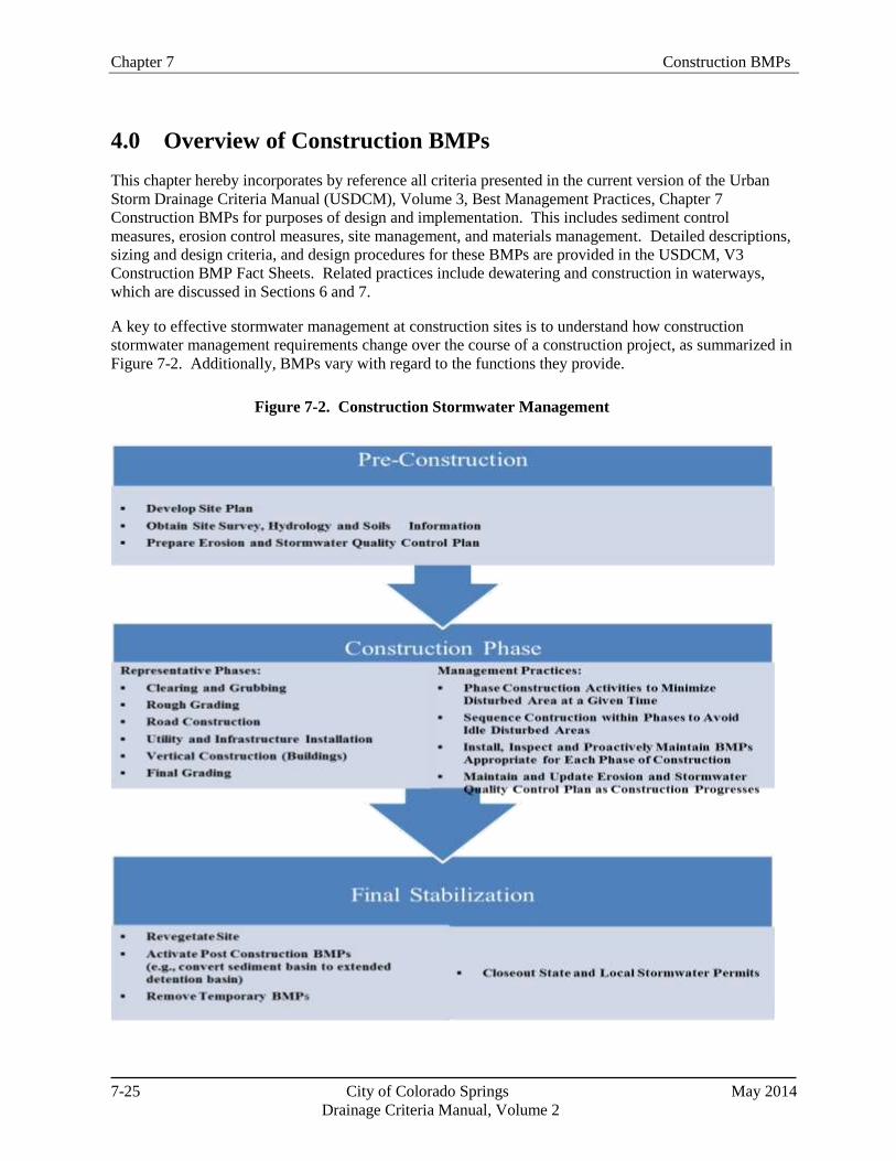
Chapter 7 Construction BMPs
7-25 City of Colorado Springs May 2014
Drainage Criteria Manual, Volume 2
4.0 Overview of Construction BMPs
This chapter hereby incorporates by reference all criteria presented in the current version of the Urban
Storm Drainage Criteria Manual (USDCM), Volume 3, Best Management Practices, Chapter 7
Construction BMPs for purposes of design and implementation. This includes sediment control
measures, erosion control measures, site management, and materials management. Detailed descriptions,
sizing and design criteria, and design procedures for these BMPs are provided in the USDCM, V3
Construction BMP Fact Sheets. Related practices include dewatering and construction in waterways,
which are discussed in Sections 6 and 7.
A key to effective stormwater management at construction sites is to understand how construction
stormwater management requirements change over the course of a construction project, as summarized in
Figure 7-2. Additionally, BMPs vary with regard to the functions they provide.
Figure 7-2. Construction Stormwater Management

Chapter 7 Construction BMPs
7-26 City of Colorado Springs May 2014
Drainage Criteria Manual, Volume 2
FunctionsErosion
Control
Sediment
Control
Site/Material
Management
Surface Roughening Yes No No
Temporary/Permanent Seeding Yes No No
Soil Binders Yes No Moderate
Mulching Yes Moderate No
Compost Blankets and Filter Berms Yes Moderate No
Rolled Erosion Control Products Yes No No
Temporary Slope Drains Yes No No
Temporary Outlet Protection Yes Moderate No
Rough Cut Street Control Yes Moderate No
Earth Dikes / Drainage Swales Yes Moderate No
Terracing Yes Moderate No
Check Dams Yes Moderate No
Streambank Stabilization Yes No No
Wind Erosion / Dust Control Yes No Moderate
Silt Fence No Yes No
Sediment Control Log Moderate Yes No
Straw Bale Barrier No Moderate No
Brush Barrier Moderate Moderate No
Rock Sock (perimeter control) No Yes No
Inlet Protection (various forms) No Yes No
Sediment Basins No Yes No
Sediment Traps No Yes No
Vegetative Buffers Moderate Yes Yes
Chemical Treatment Moderate Yes No
Concrete Washout Area No No Yes
Stockpile Management Yes Yes Yes
Good Houskeeping (multiple practices) No No Yes
Construction Phasing Moderate Moderate Yes
Protection of Existing Vegetation Yes Moderate Yes
Construction Fence No No Yes
Vehicle Tracking Control Moderate Yes Yes
Stabilized Construction Roadway Yes Moderate Yes
Stabilized Staging Area Yes Moderate Yes
Street Sweeping / Vacuuming No Yes Yes
Temporary Diversion Channel Yes No No
Dewatering Operations Moderate Yes Yes
Temporary Stream Crossing Yes Yes No
Temporary Batch Plants No No Yes
Paving and Grinding Operations No No Yes
Site Management and Other Specific Practices
Sediment Control BMPs
Erosion Control BMPs
Materials Management
Table 7-3 provides a qualitative characterization of the roles that various BMPs provide with regard to
serving erosion control functions, sediment control functions, or site/materials management roles. In
particular, it is important to understand whether the primary role of the BMP is erosion control or
sediment control. Effectively managed construction sites will provide a combination of BMPs that
provide both functions.
Table 7-3. Overview of Construction BMPs

Chapter 7 Construction BMPs
7-27 City of Colorado Springs May 2014
Drainage Criteria Manual, Volume 2
Resources for Construction
Stormwater Management/Erosion and
Sediment Control Training
Certified Professional in Erosion and
Sediment Control Program
(http://www.cpesc.org/)
Certified Inspector of Sediment and
Erosion Control Program
(http://www.cisecinc.org/)
Rocky Mountain Education Center
(http://www.rrcc.edu/rmec/cetc.html)
International Erosion Control
Association (http://www.ieca.org/)
Associated General Contractors of
Colorado (www.agccolorado.org/)
The City of Colorado Springs often hosts
training sessions. Check with the City’s
website for more information.
4.1 Erosion Control Measures
Erosion control measures are source controls used to limit
erosion of soil. These are typically surface treatments
that stabilize soil that has been exposed by excavation or
grading, although some limit erosion by redirecting flows
or reducing velocities of concentrated flow. Fact Sheets
for erosion control (EC) practices are provided in
USDCM, V3, Chapter 7. Examples of erosion control
practices include surface roughening, seeding, soil
binders, mulching, rolled erosion control products, slope
drains, and many more.
4.2 Sediment Control Measures
Sediment control measures limit transport of sediment
off-site to downstream properties and receiving waters.
Sediment controls are the second line of defense,
capturing soil that has been eroded. Sediment controls
generally rely on treatment processes that either provide
filtration through a permeable media or that slow runoff
to allow settling of suspended particles. A third treatment
process that is used in some parts of the country includes
advanced treatment systems employing chemical addition
(flocculent) to promote coagulation and settling of
sediment particles. CDPHE does not currently allow use
of chemicals. Fact Sheets for sediment control (ES) practices are provided in USDCM, V3, Chapter 7.
Examples of sediment control practices include silt fence, sediment control log, straw bale barrier, rock
sock, as well as many others.
4.3 Site Management
Site management is often ultimately the deciding factor in how effective BMPs are at a particular site.
BMPs implemented at the site must not only be properly selected and installed, but also must be
inspected, maintained and properly repaired for the duration of the construction project. In addition to
general site management, there are a number of specific site management practices that affect
construction site management. For example, effective construction scheduling (phasing and sequencing)
helps minimize the duration of exposed soils. Protection of existing vegetation also minimizes exposed
areas and can reduce the cost of final site stabilization. Stabilized construction entrances (vehicle tracking
controls) and street sweeping are critical source control measures to minimize the amount of sediment
that leaves a site. Additionally, there are several miscellaneous activities that must be carefully conducted
to protect water quality such as dewatering operations, temporary batch plants, temporary stream
crossings and other practices.
As part of the construction kick-off meeting for the project (or for major phases of construction), an
effective strategy is to include a training component related to construction site stormwater management.
Such training should provide basic education to site personnel regarding the requirements of the state and
local construction stormwater permits and the serious fines and penalties than can result from failure to
comply with permit requirements. The individual or individuals responsible for inspection and
maintenance of construction BMPs should have a practical understanding of how to maintain construction

Chapter 7 Construction BMPs
7-28 City of Colorado Springs May 2014
Drainage Criteria Manual, Volume 2
BMPs proactively in effective operating condition and to identify conditions where failure is eminent or
has already occurred. The individual performing the inspections must be a registered professional
engineer in Colorado, a certified erosion control specialist, or certified in a City-approved inspection
training program. Several training courses are available in Colorado Springs and the metro Denver area
regarding construction site stormwater management.
Fact Sheets for site management (SM) practices are provided in USDCM, V3, Chapter 7. Examples of
site management practices include construction phasing/sequencing, vehicle tracking control, protection
of existing vegetation, temporary diversion channel, as well as others.
4.4 Materials Management
Materials management BMPs are source control practices intended to limit contact of runoff with
pollutants commonly found at construction sites such as construction materials and equipment-related
fluids. By intentionally controlling and managing areas where chemicals are handled, the likelihood of
these materials being transported to waterways is reduced. Materials management (MM) BMPs Fact
Sheets are provided in USDCM, V3, Chapter 7. Examples of materials management include concrete
washout area, stockpile management, and good housekeeping.
4.5 Use of Alternative, Proprietary or Innovative Sediment and Erosion Control
(Temporary) BMPs
The toolbox of sediment and erosion control BMPs continues to expand with alternative and innovative
BMPs that become available. Many of these temporary BMPs may prove to be effective and potentially
even exceed the performance of the City approved BMPs. In recognition of this, the MS4 permittee may
allow the implementation of temporary erosion and sediment BMPs beyond those available in the DCM,
V2. Alternative or innovative temporary BMPs will be used on a limited scale and be evaluated as a pilot
program.
Requests to use alternative or innovative temporary BMPs must be submitted with the Erosion and
Stormwater Quality Control Plan. To facilitate discussions and expedite the process, it would be helpful
for the project proponent and MS4 permittee to have initial discussions on the proposed temporary BMP
prior to submitting the Erosion and Stormwater Quality Control Plan. The proposed BMP(s) must be
clearly identified as a proposed pilot BMP on the plan and adequate evidence must be given that
demonstrates that the BMP will effectively control sediment and/or erosion. The plan must include
complete design details, comprehensive installation and maintenance details, and cost estimates for
financial assurance calculations. The MS4 permittee may request additional information to evaluate the
use of this BMP. The information submitted will be used to determine if a pilot program will be allowed.
The City of Colorado Springs reserves the right to deny the use of any proposed BMP. Pilot programs
will not exceed 12 months in duration. Financial assurances are required for the pilot BMPs and
maintenance of the BMPs.
Removal of alternative or innovative temporary BMPs may be required if the BMPs fail to perform
adequately in the field. In this situation, installation of other recommended BMPs found in the Drainage
Criteria Manual, Volume 2 will be required to control erosion and sediment on the site and the Erosion
and Stormwater Quality Control Plan must be updated to reflect the BMP changes. Modifications to
correct deficiencies shall be made immediately with the inspector verifying the changes at the follow-up
inspection.
Successfully implemented alternative or innovative BMPs will be considered after thorough evaluation
for possible inclusion in the list of recommended BMPs with future revisions to the Drainage Criteria

Construction BMPs Chapter 7
7-29 City of Colorado Springs May 2014
Drainage Criteria Manual, Volume 2
Manual, Volume 2. The City of Colorado Springs also reserves the right to remove recommended BMPs
if in the future it is determined that they are not providing adequate protection.
5.0 BMP Selection and Planning
Construction BMPs should be selected, designed, installed, and maintained based on site-specific
conditions. BMPs should be selected based on the physical layout and site conditions that will exist
during each stage of construction, because site conditions change through the various stages of
construction. The number of stages that must be addressed in the Erosion and Stormwater Quality
Control Plan depends on the type of construction activity and local jurisdiction requirements, but in
general, three stages of erosion and sediment control plans can be considered. These stages include initial
clearing and grading; utility, infrastructure and building construction; and final stabilization.
Effective construction site stormwater management planning involves the following:
Collecting and analyzing site-specific information to identify needed erosion and sediment controls,
Preparing a Erosion and Stormwater Quality Control Plan that specifies needed BMPs appropriate to
each phase of construction, and
Following the Erosion and Stormwater Quality Control Plan, maintaining BMPs and updating the
Erosion and Stormwater Quality Control Plan as construction progresses.
This section focuses on important factors to consider in the development of an Erosion and Stormwater
Quality Control Plan, including site-specific conditions, BMP functions, and other site-related plans.
5.1 Site Assessment
Early awareness of site-specific factors that make a site particularly prone to erosion problems can
prevent serious problems later during the construction process. A site assessment should include attention
to these factors, prior to selection of BMPs:
Slopes/Topography and Topographic Changes Due to Grading: Slope length and steepness are
two key factors in identifying the types and placement of both erosion and sediment control BMPs.
Slopes will change throughout the phases of construction as grading is conducted. See Sections 5.2
and 5.3 for additional guidance.
Tributary Area/Catchment Size: The overall size of sub-catchment areas prior to and following
grading is a key factor in determining the types, sizes, spacing and other design requirements for
sediment controls appropriate for each drainage area. The allowable tributary area for sediment
controls varies, depending on the practice selected, as described in the BMP Fact Sheets.
Soils: Regardless of soil type, all disturbed soils require erosion controls; however, NRCS soil maps
and geotechnical reports for the development can be used to identify soil conditions where erosion
may be particularly difficult to control. In such settings, additional layers of protection for both
erosion and sediment controls may be needed and planned for proactively in the Erosion and
Stormwater Quality Control Plan.
Vegetation: Onsite vegetation that is to be left undisturbed must be clearly identified in the Erosion
and Stormwater Quality Control Plan and/or the construction plans. Construction fence should be
installed to avoid disturbance and compaction of these areas. This is particularly important for

Chapter 7 Construction BMPs
7-30 City of Colorado Springs May 2014
Drainage Criteria Manual, Volume 2
Photograph 7-2. Diverting the upland slope drainage area may have
avoided the rilling shown in this picture.
protection of mature trees, natural riparian buffers and wetlands, natural open space, or other areas
specifically identified to be protected from compaction as part of Low Impact Development (LID)
designs. Maintaining a vegetative buffer, in combination with other perimeter control BMPs, can be
effective for minimizing transport of sediment off-site.
Drainage Infrastructure: Understanding the hydrology of a site is important in the design of
sediment controls. Offsite run-on as well as drainage patterns within the site should be thoroughly
assessed. The configuration of hill slope areas and waterways, in the context of planned roads and
buildings, will determine which erosion and sediment controls will be needed at each phase of
construction.
Sensitive Site Conditions: In cases where construction is occurring in areas of sensitive aquatic
habitat, upstream of drinking water supplies, or near areas where threatened and endangered species
are a concern, additional layers of protection may be specified by the local, state or federal
government. These may include redundant BMPs or restrictions on times that construction activities
are allowed.
5.2 Slope-Length and Runoff
Considerations
Cut-and-fill slopes should be designed
and constructed to minimize erosion.
This requires consideration of the length
and steepness of the slope, the soil type,
upslope drainage area, groundwater
conditions and other applicable factors.
Slopes found to be eroding excessively
will require additional slope stabilization
until the problem is corrected. The
following guidelines should assist site
planners and plan reviewers in
developing an adequate design:
Rough soil surfaces enhance
infiltration and/or lengthen the travel
path or runoff, reducing runoff
velocity. See the Surface Roughening BMP Fact Sheet.
Temporary diversion dikes should be constructed at the top of long or steep slopes. Diversion dikes
or terraces reduce slope length within the disturbed area. See the Earth Dikes and Drainage Swales
BMP Fact Sheet.
Temporary diversion dikes should be provided whenever:
S2L > 2.5 for undisturbed tributary areas; Equation 7-1
S2L > 1.0 for disturbed tributary areas; Equation 7-2
S2L > 0.25 for paved tributary areas; Equation 7-3
where:
Construction BMPs Chapter 7
7-31 City of Colorado Springs May 2014
Drainage Criteria Manual, Volume 2
S = slope of the upstream tributary area (feet/foot)
L = length of the upstream slope (feet)
As an example, runoff from a developed area runs on to an area that will be disturbed. A
diversion dike would be required if, for example, the length of the flow path was greater than 625
feet and the slope of the flow path was 2%.
Concentrated stormwater (e.g., pipe outflow, channel, swale) should not be allowed to flow down cut
or fill slopes unless contained within an adequately-sized temporary channel diversion, a permanent
channel, or temporary slope drain. See the Temporary Slope Drain and Diversion Ditches/Channels
BMP Fact Sheets.
Wherever a slope face crosses a water seepage plane that endangers the stability of the slope,
adequate drainage should be provided.
Provide sediment basins or barriers (silt fence) at or near the toe of slopes to trap sediment or to
reduce slope lengths. When flows are concentrated and conveyed down a slope using a slope drain or
channel, energy dissipation measures will be required at the conveyance outlet at the toe of the slope.
See the Sediment Control BMP Fact Sheets for several options for controlling sediment at the base of
slopes.
5.3 Using the Revised Universal Soil Loss Equation
The Revised Universal Soil Loss Equation (RUSLE) is an erosion prediction method that has evolved
over time, resulting from data collection and analysis efforts extending from the 1930s through the 1970s,
ultimately published in Agriculture Handbook 282 (Wischmeier and Smith, 1965), then Agriculture
Handbook 537 (Wischmeier and Smith, 1978) and Agriculture Handbook 703 (Renard et al., 1997).
Although originally developed for agricultural land use, it is also a useful method for estimating erosion
potential on construction sites and adjusting BMPs to reduce the estimated erosion. The RUSLE is also
incorporated into several modern erosion prediction models. The Modified Universal Soil Loss Equation
(MUSLE) is similar to the RUSLE, but is differentiated by the fact that MUSLE is event-based while
RUSLE is an annual method (with the option to calculate monthly or seasonal erosion). This section
provides a brief overview of RUSLE and describes how it can be used to help select erosion control
practices at construction sites.
A = RKLSCP Equation 7-4
where:
A = Computed spatial average soil loss and temporal average soil loss per unit of area, expressed in
the units selected for K and for the period selected for R. Typically, A is expressed in tons per
acre per year.
R = Rainfall-runoff erosivity factor – the rainfall erosion index plus a factor for any significant
runoff from snowmelt.
K = Soil erodibility factor – the soil-loss rate per erosion index unit for a specified soil.
L = Slope length factor – the ratio of soil loss from the field slope length to soil loss from a 72.6 ft
length under identical conditions.

Chapter 7 Construction BMPs
7-32 City of Colorado Springs May 2014
Drainage Criteria Manual, Volume 2
S = Slope steepness factor – the ratio of soil loss from the field slope gradient to soil loss from a 9
percent slope under otherwise identical conditions.
C = Cover-management factor – the ratio of soil loss from an area with specified cover and
management to soil loss from an identical area in a bare condition. Values range from 0.01 to 1.
P = Erosion control practice factor – the ratio of soil loss with a certain conservation practice
(erosion control BMP) to that of no practice. Values range from 0.8 to 1.2.
The slope length, L, and steepness factor, S, are commonly combined as one variable, LS. Values for LS
are quantified relative to a 72.6 ft slope length with a 9 percent slope. A slope with these two values will
have an LS factor of 1.
A detailed discussion of RUSLE factors is beyond the scope of this manual; however, Agriculture
Handbook 703 can be obtained at no charge from the USDA publications website and used to develop or
obtain values for the factors in the equation. Construction managers can use the RUSLE, either by hand
or by using a variety of different software programs based on the equation, to evaluate how implementing
various BMPs can help reduce surface erosion. Highly erosive sites or sites with sensitive receiving
waters may benefit from more rigorous analysis using the RUSLE.
Although construction managers have no control over the A and R factors, factors L, S, C and P can be
altered by implementing practices that reduce sediment loading. One technique to reduce the slope length
and steepness is to terrace. For example, if a portion of a construction area has a slope length of 500 feet,
it can be terraced into three or four equal sections to reduce the erosivity of the water coming down the
slope. This factor can also be used to guide placement distances for silt fence, wattles and other practices
that serve to break up the slope length. As another example, construction managers can vary cover
management practices to decrease the C factor and reduce sediment loading. C values vary, depending on
the type of cover implemented. Using the reference table for the C value, managers can select cover
approaches to help reduce sediment loading. Finally, the practice factor (P) serves as an index of
anticipated erosion reduction associated with various erosion control BMPs.
5.4 BMP Functions
Understanding the intended function of a BMP is critical to proper BMP selection. BMPs should be
selected based on both the intended function of the BMP and consideration of whether the BMP can
provide the desired function based on the site-specific conditions. It is also important to understand how
BMP functions are related to maintenance. For example, when silt fence is initially installed, it provides a
filtration function, but over time, the fabric can become clogged, leading to ponding and sedimentation
behind the fence as the primary function rather than filtration.
Sediment control BMPs such as sediment basins can provide some settling of sediment from runoff, but
must be combined with erosion controls throughout the site in order to be effective. Sediment basins,
inlet protection, and other sediment control BMPs should not be solely relied upon as "end-of-pipe"
treatment systems.
5.5 Consistency with Other Plans
Prior to selection of BMPs for the Erosion and Stormwater Quality Control Plan, it is important to cross-
check other construction planning documents for consistency and/or opportunities for increased
efficiencies and effectiveness. As an example, landscaping plans for a site should be consistent with final
stabilization measures in the Erosion and Stormwater Quality Control Plan.

Construction BMPs Chapter 7
7-33 City of Colorado Springs May 2014
Drainage Criteria Manual, Volume 2
5.5.1 Drainage Plans
The Erosion and Stormwater Quality Control Plan should be prepared with due consideration of the final
drainage plan for a development. As permanent drainage features are constructed, temporary sediment
controls should be located and designed to both protect and complement these final drainage features.
Temporary controls should be staged and removed at the appropriate time relative to the completion of
permanent drainage features. Special care is necessary for permanent BMPs that rely on infiltration such
as bioretention, permeable pavements, sand filters and others. These BMPs will clog if they are not
adequately protected during construction (or constructed after tributary areas have been stabilized).
5.5.2 Post Construction Stormwater Management
Coordination of temporary and post-construction BMPs is important for several reasons. In some cases,
post construction BMPs such as extended detention basins can be modified to serve as sedimentation
basins during construction. In other cases, such as in the case of rain gardens or infiltration-oriented post-
construction BMPs, it is critically important to protect the post-construction facilities from sediment
loading during construction. Also, as previously noted, if an area is targeted for preservation in an
uncompacted, natural condition under a LID design, it is critical to keep heavy equipment and staging out
of this area.
5.5.3 Air Quality Plans
Properly implemented erosion and sediment control BMPs are beneficial in minimizing wind erosion.
For example, surface stabilization measures that help to reduce precipitation-induced erosion help to
reduce windborne dust and sediment. Additional controls, such as road watering (to moisten roads but
not to the extent that runoff results) and/or soil binders may be necessary to fully comply with fugitive
dust regulations at a construction site.
5.6 Integrating Site Conditions and BMPs into an Erosion and Stormwater Quality
Control Plan
The following guidelines are recommended when combining BMPs into an effective Erosion and
Stormwater Quality Control Plan:
Determine the limits of clearing and grading: If the entire site will not undergo excavation and
grading, or excavation and grading will occur in stages, the boundaries of each cut-and-fill operation
should be defined. Buffer strips of natural vegetation may be utilized as a control measure. Adequate
protection of both tree limbs and root systems is important when specifying limits of construction
activity. Use construction fence or other barriers to protect areas that should not be compacted or
disturbed.
Define the layout of buildings and roads: Typically, this will have been decided previously as a
part of the general development plan. If building layout is not final, the road areas stabilized with
pavement and the drainage features related to roads should be defined as they relate to the plan.
Determine permanent drainage features: The location of permanent channels, storm sewers,
roadside swales and stormwater quality controls such as ponds, wetlands, grassed-lined swales, buffer
strips and areas of porous pavement, if known, should be defined.
Determine extent of temporary channel diversions and crossings: If permanent channel
improvements are a part of the plan, the route, sizing and lining needed for temporary channel

Chapter 7 Construction BMPs
7-34 City of Colorado Springs May 2014
Drainage Criteria Manual, Volume 2
diversions should be determined. Location and type of temporary channel crossings can be assessed.
Determine the boundaries of watersheds: The size of drainage catchments will determine the types
of sediment controls to be used. Areas located offsite that contribute runoff must be assessed.
Measures to limit the size of upland drainage areas, such as diversion dikes, should be considered at
this stage. Routing offsite "clean" runoff around areas of disturbance in stabilized conveyances
reduces the burden on onsite measures and can reduce liability of the owner/developer—once offsite
runoff enters the permitted construction area, the owner/developer is responsible for erosion and
sediment transport resulting from the offsite runoff.
Select erosion controls: All areas of exposed soil will require erosion control measures based on
factors including the duration of exposure, soil erosivity, slope steepness, and length, and others.
Select sediment controls: Select the controls needed for each stage of the construction project. Each
stage will have different demands for the control of erosion and sedimentation. For example, over-lot
grading will require controls that may require different BMPs than when individual homes are being
built and lots are disturbed after the streets and drainage systems are in place. Sediment basins are an
essential part of the total plan when the tributary area exceeds one acre.
Determine sequencing of construction: The schedule of construction will determine what areas
must be disturbed at various stages throughout the development plan. The opportunity for phasing
cut-and-fill operations to minimize the period of exposure of soils needs to be assessed and then
incorporated into the Erosion and Stormwater Quality Control Plan.
Identify planned locations of topsoil stockpiles: Areas for storing topsoil should be determined and
proper measures to control erosion and sediment movement should be specified.
Identify planned location of temporary construction roads, vehicle tracking controls, portable
toilets, waste disposal areas, and material storage areas: These elements can be determined in the
context of previously defined parts of the site construction management plan.
6.0 Construction Dewatering
Dewatering is typically necessary during construction activities that involve deep excavations, instream
work, pumped surface diversions, and open trench operations in some cases. In Colorado, construction
dewatering frequently requires a separate state permit along with sample collection and the completion of
Discharge Monitoring Reports (DMRs). When dewatering can be conducted without discharging surface
runoff from the site, it may be possible to conduct such activities under the state Construction-phase
Stormwater Permit. Some commonly used methods to handle the pumped water without surface
discharge include land application to vegetated areas through a perforated discharge hose (i.e., the
"sprinkler method") or dispersal from a water truck for dust control. Carefully check state permit
requirements to determine when dewatering can be conducted without additional permitting.
Construction dewatering BMPs generally include practices to minimize turbidity in the pumped water.
Representative practices that may help to reduce turbidity in various types of dewatering applications
include:
Using perimeter well points outside of the excavated area to draw down the water table rather than
dewatering directly from the excavation;
Placing a submersible pump in a perforated bucket filled with gravel for short-term pumping;

Construction BMPs Chapter 7
7-35 City of Colorado Springs May 2014
Drainage Criteria Manual, Volume 2
Constructing a filtering sump pit for pumping groundwater below the excavation grade for multiple-
day operations; or
Using a flotation collar or other flotation device to pump from the surface of a sediment basin to
avoid the silt that can accumulate on the bottom of the basin.
Guidance on BMPs for construction dewatering is provided on the Dewatering Operations Fact Sheet.
7.0 Construction in Waterways
Construction in waterways is often required for projects including bridge construction, utility
construction, streambank stabilization and grade control, and temporary or permanent stream crossings.
Construction in waterways requires a high standard of care in order to avoid and minimize damage to
waterways, habitat, and aquatic life. In addition to the construction phase permits already discussed, this
work can also require a Clean Water Act Section 404 Permit from USACE, U.S. Fish and Wildlife
Service (USFWS) threatened and endangered species permitting, and/or other state and local permits.
Some required permits may restrict construction to certain times of the year.
Many of the BMPs described in Section 4 of this chapter are used in waterway construction. This section
provides guidance on factors to consider and plan for during construction in waterways, as well as
guidance on specific BMPs that should be implemented, depending on site-specific conditions. Other
criteria and guidance that are closely related to in-stream work should also be referenced including:
Drainage Criteria, Volume 1 Major Drainage Chapter
Drainage Criteria, Volume 1 Revegetation Chapter
Drainage Criteria, Volume 1 Hydraulic Structures Chapter
Stormwater Management During Construction: Best Management Practices for Construction in
Waterways Training Program Student Manual (Altitude Training Associates 2008). This document
is available for download on www.udfcd.org.
BMPs provided in this chapter that are commonly used when construction occurs in waterways include
surface roughening, soil binders, mulching, earth dikes, temporary channel diversion channel; temporary
stream crossing, as well as many others.
In addition to criteria specified for these BMPs, the following general principles should be followed:
Construction vehicles should be kept out of a waterway to the maximum extent practicable.
Where in-channel work is necessary, steps such as temporary channel diversions must be taken to
stabilize the work area and control erosion during construction.
When in-stream work has been completed, the channel must be stabilized using revegetation practices
(often, including use of erosion control matting or turf reinforced mats), riprap, or other permanent
stabilization measures as required by the Erosion and Stormwater Quality Control Plan.
Where an actively-flowing watercourse must be crossed regularly by construction vehicles, a
temporary crossing should be provided. Three primary methods are available: (1) a culvert crossing,
(2) temporary bridge, and (3) a stream ford. See the Temporary Stream Crossing Fact Sheets.
Chapter 7 Construction BMPs
7-36 City of Colorado Springs May 2014
Drainage Criteria Manual, Volume 2
404 Permit Basics
Section 404 of the Federal Clean Water Act established a program to regulate the discharge of dredged
and fill material into waters of the United States, including wetlands. Responsibility for administering
and enforcing Section 404 is shared by the U.S. Army Corps of Engineers (USACE) and EPA. USACE
administers the day-to-day program, including individual permit decisions and jurisdictional
determinations; develops policy and guidance; and enforces Section 404 provisions. EPA develops and
interprets environmental criteria used in evaluating permit applications, identifies activities that are
exempt from permitting, reviews/comments on individual permit applications, enforces Section 404
provisions, and has authority to veto USACE permit decisions.
A Section 404 permit is typically required when the following activities are conducted in waters of the
U.S., including wetlands:
Construction of roads or paths
Foundations or amenities for residential, commercial, or recreational developments
Construction of ponds, dams, dikes or weirs
Placement of riprap and channel protection
Laying utility pipes or lines
A permit is required for placement of fill in a waterway under Section 404 of the Clean Water Act.
The local office of the USACE should be contacted concerning the requirements for obtaining a 404
permit. In addition, a permit from USFWS may be needed if threatened or endangered species are of
concern in the work area. Typically, the USFWS issues are addressed in conjunction with the 404
permit if one is required. A floodplain development permit and other local permits may also be
required.
When work takes place within a channel, a temporary water diversion to bypass the work area is
typically required. See the Diversion Channel/Ditch BMP Fact Sheet for criteria and design details.
To the extent practical, construction in a waterway should be sequenced to begin at the most
downstream point and work progressively upstream installing required channel and grade control
facilities.
Complete work in small segments, exposing as little of the channel at a time as practical. Keep
equipment operators contained in immediate work area and avoid excessive compacting of the soil
surface because it inhibits revegetation.
Where feasible, it is best to perform in-channel work between October 1 and March 31 in Colorado.
This is the period when the chances of flash floods and flows higher than the 2-year flood peak flows
are less likely.
During the process of cut and fill, avoid letting side-cast or waste material enter waterways or placing
it on unstable areas. Instead, efficiently move excavated material to areas needing fill or to a
stockpile. For stream restoration/stabilization projects, consulting with a fluvial geomorphologist on
stream stability issues may be prudent.

Construction BMPs Chapter 7
7-37 City of Colorado Springs May 2014
Drainage Criteria Manual, Volume 2
When selecting BMPs for in-stream construction, a variety of factors should be considered such as:
Hydrologic factors (tributary watershed size,
length of the overland flow, roughness and
slope characteristics, precipitation
characteristics, imperviousness, etc.)
Baseflow conditions
Pollutants that may be delivered to the
waterway from the surrounding area
Extent of existing erosion, headcutting or
bank sloughing
Condition/type of vegetation and percent
cover
Sources of surface runoff
Drainage pattern
Historic events
Flow regulation (ditch diversions, reservoir
releases)
8.0 Considerations for Linear Construction Projects
Linear projects involving utilities, streets, highways, railways, and other transportation-related projects
can pose some unique stormwater management challenges during construction. Section 8.1 identifies
special considerations and approaches that may be beneficial to linear projects, and Section 8.2 provides
criteria for trenching for underground utility lines.
8.1 General Considerations
General considerations for linear construction projects include:
Standard Details for Typical Activities: Development of a set of standard BMP details for typical
construction activities can promote consistent implementation of erosion and sediment control
measures and more efficient Erosion and Stormwater Quality Control Plan preparation. For example,
if a utility company frequently installs light poles, it may be beneficial to develop a standard detail
showing the typical construction of a light pole and the associated BMPs. Typical details for
construction activities can be used by contractors allowing them to know what BMPs must be used
for specific construction activities. BMP details shall be shown on the Erosion and Stormwater
Quality Control Plans. BMPs must be indicated on the site map if site-specific conditions vary from
the conditions assumed for development of the typical construction activity BMP detail.
Construction Phasing: By nature, linear construction activities are typically phased. Phasing often
will be dictated by the extent of allowable traffic closures and typical requirements for closing
trenches at the end of the workday in the right-of-way. For linear construction projects in the public
right-of-way, stabilization often can be achieved rapidly as each segment or phase of the project is
completed, often by paving or repairing and/or installing sod. For areas where revegetation is from
seed, reaching final stabilization (and inactivating stormwater permit coverage) will be a lengthier
process.
Weather and Climate: Linear projects such as roadwork may need to consider seasonal weather
patterns when scheduling construction. Bridgework over waterbodies should be planned during
traditionally low water levels, October 1 to March 31 when possible. Utility projects should attempt
to close trenches prior to inclement weather, if feasible, and at the end of each day.
Chapter 7 Construction BMPs
7-38 City of Colorado Springs May 2014
Drainage Criteria Manual, Volume 2
Space Constraints: Select BMPs that work best under the space constraints of the project. Many
utility and road construction projects in urban areas have BMPs that are located in active streets.
Durability: Particularly in active traffic areas, durability of BMPs (i.e., ability to continue to
function properly, even when run over by a vehicle) is an important consideration for BMP selection.
Potential for Ponding: Creation of ponded water on roadways may also be a concern. It is
important to keep in mind that inlet protection can function in two different ways: filtration and/or
ponding. While both of these mechanisms can play a role in sediment removal, typically, inlet
protection methods that encourage filtration and limit the amount of ponding are favorable, since
ponding typically does not provide enough storage for significant residence time/settling and because
ponding can impede travel in streets and highways. Ponding, which occurs to at least some degree
with most types of inlet protection, can typically be addressed by selection of the appropriate type of
inlet protection, frequent maintenance/sediment removal, and providing an overflow path that will not
cause flooding in the event that excessive ponding occurs.
Temporary Access: Unlike a typical residential or commercial development where there are access
points that will be used throughout the duration of the project, for linear construction projects, it is
often necessary to access the work area for limited periods of time at multiple locations throughout
the corridor. For utility projects where access through vegetated areas is necessary at multiple
locations, but generally only for a limited amount of time at each location, consider alternatives to
standard geotextile and rock-lined vehicle tracking control pads such as construction mats or turf
reinforced mats for temporary access to avoid disturbance to vegetation and soil that is typically
associated with traditional vehicle tracking control pads.
Jurisdictional Considerations: Linear projects are often multijurisdictional. In these cases, it is
important to have upfront coordination with the municipalities that are involved to reduce the burden
of permitting and Erosion and Stormwater Quality Control Plan preparation to the extent practical.
For example, it may be possible to prepare a single Erosion and Stormwater Quality Control Plan that
will satisfy the requirements of multiple municipalities rather than preparing separate Erosion and
Stormwater Quality Control Plans for work in each municipality.
8.2 Underground Utility Trenching Criteria
Specific criteria for trenching activities include:
Minimize the length of trench open at one time to the extent practical. For most trenching projects, it
should be feasible to phase construction so that no more than a few hundred feet of trench are open at
any given time.
Where consistent with safety and space considerations, place excavated material on the upgradient
side of trenches.
Trench dewatering devices must discharge in a manner that will not cause erosion or adversely affect
flowing streams, wetlands, drainage systems, or off-site property. See the Dewatering Operations
BMP Fact Sheet and Section 6 of this chapter for additional guidance.
Provide storm sewer inlet protection whenever soil erosion from the excavated material has the
potential to enter the storm drainage system. See Inlet Protection BMP Fact Sheet for specific
guidance.
Construction BMPs Chapter 7
7-39 City of Colorado Springs May 2014
Drainage Criteria Manual, Volume 2
Evaluate potential for sediment contributions to inlets or receiving waters that are not in the
immediate vicinity of the work area and implement inlet protection and/or other BMPs as necessary.
For example, if vehicles access the construction area to remove excavated material or to deliver
materials, evaluate the potential for offsite sediment tracking and implement measures such as street
sweeping, inlet protection, stabilized access to the construction area, and other BMPs to protect inlets
or receiving waters that could be affected by tracked sediment. As another example, perimeter
controls on the upgradient side of stockpiles and inlet protection on the opposite side of the crown of
the street may be necessary if stockpile height or tracking from accessing stockpiles has the potential
to contribute sediment to the opposite side of the street.
9.0 Construction BMP Fact Sheets
The Construction BMP Fact Sheets included in the UDFCD Manual, Volume 3 are applicable.
10.0 Map Symbols
The map symbols shown at the back of this chapter shall be used to represent the construction BMP
features.
11.0 References
Altitude Training Associates. 2008. Stormwater Management During Construction: Best Management
Practices for Construction in Waterways Training Program Student Manual. www.udfcd.org
Colorado Department of Public Health and Environment Water Quality Control Division. 2007. CDPS
General Permit, Stormwater Discharges Associated with Construction Activity.
U.S. Environmental Protection Agency (EPA). 2009. Effluent Limitations Guidelines and Standards for
the Construction and Development Point Source Category, Final Rule. December 1, 2009.
Federal Register, Part III Environmental Protection Agency, 40 CFR Part 450. 74 (229):
62997-63057.
Renard, K.G., G.R. Foster, G.A. Weesies, D.K. McCool, and D.C. Yoder, coordinators. 1997. Predicting
Soil Erosion by Water: A Guide to Conservation Planning with the Revised Universal Soil Loss
Equation. U.S. Department of Agriculture, Agriculture Handbook 703. 384pp.
http://ddr.nal.usda.gov/dspace/bitstream/10113/11126/1/CAT10827029.pdf
Wischmeier, W.H. and D.D. Smith. 1965. Predicting rainfall-erosion losses from cropland east of the
Rocky Mountains. Agriculture Handbook No. 282, US Dept. of Agriculture. Washington, DC.
Wischmeier, W.H. and D.D. Smith. 1978. Predicting rainfall erosion losses: A guide to conservation
planning. Agriculture Handbook No. 537, US Dept. of Agriculture. Washington, DC.

Chapter 7 Construction BMPs
7-40 City of Colorado Springs May 2014
Drainage Criteria Manual, Volume 2
Map Symbols

Construction BMPs Chapter 7
7-41 City of Colorado Springs May 2014
Drainage Criteria Manual, Volume 2
Map Symbols (cont’d)
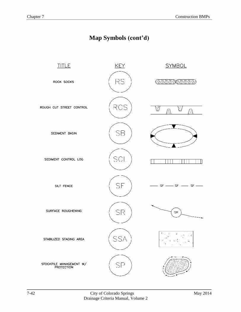
Chapter 7 Construction BMPs
7-42 City of Colorado Springs May 2014
Drainage Criteria Manual, Volume 2
Map Symbols (cont’d)

Construction BMPs Chapter 7
7-43 City of Colorado Springs May 2014
Drainage Criteria Manual, Volume 2
Map Symbols (cont’d)
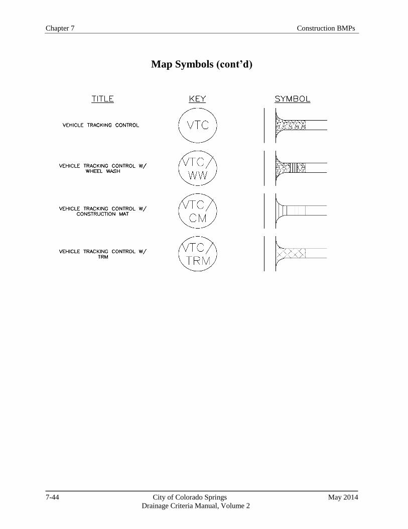
Chapter 7 Construction BMPs
7-44 City of Colorado Springs May 2014
Drainage Criteria Manual, Volume 2
Map Symbols (cont’d)