Drag-and-Drop Pasting - Chinese University of Hong …Figure 1: Drag-and-Drop Pasting. Given a...
6
Copyright © 2006 by the Association for Computing Machinery, Inc. Permission to make digital or hard copies of part or all of this work for personal or classroom use is granted without fee provided that copies are not made or distributed for commercial advantage and that copies bear this notice and the full citation on the first page. Copyrights for components of this work owned by others than ACM must be honored. Abstracting with credit is permitted. To copy otherwise, to republish, to post on servers, or to redistribute to lists, requires prior specific permission and/or a fee. Request permissions from Permissions Dept, ACM Inc., fax +1 (212) 869-0481 or e-mail [email protected] . © 2006 ACM 0730-0301/06/0700- $5.00 0631 Drag-and-Drop Pasting Jiaya Jia 1 Jian Sun 2 Chi-Keung Tang 3 Heung-Yeung Shum 2 1 The Chinese University of Hong Kong 2 Microsoft Research Asia 3 The Hong Kong University of Science and Technology (a) (b) (c) (d) (e) Figure 1: Drag-and-Drop Pasting. Given a source image (a), the user draws a boundary that circles the wood log and its shadow in the water, and drags and drops this region of interest onto the target image in (b). The result from Poisson image editing (c) is however not satisfactory. Structures in this target image (e.g., the dark beach) intersect the source region boundary, thus produce unnatural blurring after solving the Poisson equations. Our approach, called drag-and-drop pasting, computes an optimized boundary shown in (d), which is then used to generate a seamless image composite (e). Abstract In this paper, we present a user-friendly system for seamless image composition, which we call drag-and-drop pasting. We observe that for Poisson image editing [Perez et al. 2003] to work well, the user must carefully draw a boundary on the source image to indicate the region of interest, such that salient structures in source and target images do not conflict with each other along the boundary. To make Poisson image editing more practical and easy to use, we propose a new objective function to compute an optimized boundary con- dition. A shortest closed-path algorithm is designed to search for the location of the boundary. Moreover, to faithfully preserve the object’s fractional boundary, we construct a blended guidance field to incorporate the object’s alpha matte. To use our system, the user needs only to simply outline a region of interest in the source image, and then drag and drop it onto the target image. Experimental re- sults demonstrate the effectiveness of our “drag-and-drop pasting” system. Keywords: Image processing, Poisson image editing, Image com- positing 1 Introduction Image composition is the process of creating a new image by past- ing an object or a region from a source image onto a target image. Poisson image editing [Perez et al. 2003] has been proposed re- cently as an effective approach for seamless image composition. By solving Poisson equations using the user-specified boundary condi- tion, Poisson image editing seamlessly blends the colors from both images without visible discontinuities around the boundary. Pois- son image editing not only has an elegant mathematical formula- tion, but also appears to be easy to use. The effectiveness of Poisson image editing, however, depends on how carefully the user draws the boundary. As shown in Fig- ure 1, Poisson image editing may not always produce good results. Given source and target images in Figures 1(a) and (b), and the blue boundary casually drawn by the user, Figure 1(c) shows that Poisson image editing may generate unnatural blurring artifacts at places where the boundary intersects with salient structures in the target image (e.g. the dark beach at the top). To obtain seamless composition, we observe that the user needs to take the target image into consideration before drawing the boundary for Poisson image editing. In this paper, we propose a method to optimize the boundary con- dition for Poisson image editing. With the optimized boundary shown in Figure 1(d), we again apply Poisson image editing to ob- tain seamless composition as shown in Figure 1(e). We note that in Figure 1(d) the optimized boundary avoids as much as possible salient image structures on both source and target images. To optimize the boundary condition, we propose a new objective function which is iteratively minimized using a shortest closed-path algorithm. We search for the optimal boundary in between what the user casually draws (the region of interest) and what the user really cares about (the object of interest). Compared with the original Poisson image editing, our system allows the user to easily drag the region of interest from the source image and to drop it onto the target image, without the need for careful specification of the optimal boundary. Often, the optimized boundary may intersect with the object of in- terest. In this case, fine structures of the object may be missing after blending with the target image through Poisson equations. We introduce a blended guidance field to integrate an alpha matte into Poisson equations to faithfully preserve the fractional boundary of the object and produce more natural image composite. 2 Related work Image matting is a common way to extract an object from a source image which can then be pasted onto a target image naturally using an alpha channel. Most matting methods require a trimap in or- der to estimate the alpha channel and foreground color. There has been a lot of work on natural image matting using a single image [Berman et al. 2000; Ruzon and Tomasi 2000; Chuang et al. 2001; 631
Transcript of Drag-and-Drop Pasting - Chinese University of Hong …Figure 1: Drag-and-Drop Pasting. Given a...

Copyright © 2006 by the Association for Computing Machinery, Inc. Permission to make digital or hard copies of part or all of this work for personal or classroom use is granted without fee provided that copies are not made or distributed for commercial advantage and that copies bear this notice and the full citation on the first page. Copyrights for components of this work owned by others than ACM must be honored. Abstracting with credit is permitted. To copy otherwise, to republish, to post on servers, or to redistribute to lists, requires prior specific permission and/or a fee. Request permissions from Permissions Dept, ACM Inc., fax +1 (212) 869-0481 or e-mail [email protected]. © 2006 ACM 0730-0301/06/0700- $5.00 0631
Drag-and-Drop Pasting
Jiaya Jia1 Jian Sun2 Chi-Keung Tang3 Heung-Yeung Shum21The Chinese University of Hong Kong 2Microsoft Research Asia
3The Hong Kong University of Science and Technology
PSfrag replacements
(a) (b) (c) (d) (e)(f)
Figure 1: Drag-and-Drop Pasting. Given a source image (a), the user draws a boundary that circles the wood log and its shadow in the water, and drags and drops this region ofinterest onto the target image in (b). The result from Poisson image editing (c) is however not satisfactory. Structures in this target image (e.g., the dark beach) intersect the sourceregion boundary, thus produce unnatural blurring after solving the Poisson equations. Our approach, called drag-and-drop pasting, computes an optimized boundary shown in (d),which is then used to generate a seamless image composite (e).
AbstractIn this paper, we present a user-friendly system for seamless imagecomposition, which we call drag-and-drop pasting. We observe thatfor Poisson image editing [Perez et al. 2003] to work well, the usermust carefully draw a boundary on the source image to indicate theregion of interest, such that salient structures in source and targetimages do not conflict with each other along the boundary. To makePoisson image editing more practical and easy to use, we proposea new objective function to compute an optimized boundary con-dition. A shortest closed-path algorithm is designed to search forthe location of the boundary. Moreover, to faithfully preserve theobject’s fractional boundary, we construct a blended guidance fieldto incorporate the object’s alpha matte. To use our system, the userneeds only to simply outline a region of interest in the source image,and then drag and drop it onto the target image. Experimental re-sults demonstrate the effectiveness of our “drag-and-drop pasting”system.Keywords: Image processing, Poisson image editing, Image com-positing
1 Introduction
Image composition is the process of creating a new image by past-ing an object or a region from a source image onto a target image.Poisson image editing [Perez et al. 2003] has been proposed re-cently as an effective approach for seamless image composition. Bysolving Poisson equations using the user-specified boundary condi-tion, Poisson image editing seamlessly blends the colors from bothimages without visible discontinuities around the boundary. Pois-son image editing not only has an elegant mathematical formula-tion, but also appears to be easy to use.
The effectiveness of Poisson image editing, however, depends on
how carefully the user draws the boundary. As shown in Fig-ure 1, Poisson image editing may not always produce good results.Given source and target images in Figures 1(a) and (b), and theblue boundary casually drawn by the user, Figure 1(c) shows thatPoisson image editing may generate unnatural blurring artifacts atplaces where the boundary intersects with salient structures in thetarget image (e.g. the dark beach at the top). To obtain seamlesscomposition, we observe that the user needs to take the target imageinto consideration before drawing the boundary for Poisson imageediting.
In this paper, we propose a method to optimize the boundary con-dition for Poisson image editing. With the optimized boundaryshown in Figure 1(d), we again apply Poisson image editing to ob-tain seamless composition as shown in Figure 1(e). We note thatin Figure 1(d) the optimized boundary avoids as much as possiblesalient image structures on both source and target images.
To optimize the boundary condition, we propose a new objectivefunction which is iteratively minimized using a shortest closed-pathalgorithm. We search for the optimal boundary in between what theuser casually draws (the region of interest) and what the user reallycares about (the object of interest). Compared with the originalPoisson image editing, our system allows the user to easily dragthe region of interest from the source image and to drop it ontothe target image, without the need for careful specification of theoptimal boundary.
Often, the optimized boundary may intersect with the object of in-terest. In this case, fine structures of the object may be missingafter blending with the target image through Poisson equations. Weintroduce a blended guidance field to integrate an alpha matte intoPoisson equations to faithfully preserve the fractional boundary ofthe object and produce more natural image composite.
2 Related work
Image matting is a common way to extract an object from a sourceimage which can then be pasted onto a target image naturally usingan alpha channel. Most matting methods require a trimap in or-der to estimate the alpha channel and foreground color. There hasbeen a lot of work on natural image matting using a single image[Berman et al. 2000; Ruzon and Tomasi 2000; Chuang et al. 2001;
631
1 12 2
PSfrag replacements
+
=
=
(a) (b)
(c) (d)
(e)
Boundary condition before and after optimization
Figure 2: Comparison of the boundary conditions. (a) and (c) are results by solvingPoisson equations with different boundary conditions. They are equivalent to adding(b) and (d) to the source image fs shown in (e) respectively. (b) and (d) are results bysolving the corresponding Laplace equations. The red curves are boundaries while therectangular shaded areas are caused by the difference of the source and result images.The bottom row shows the boundaries in (b) and (d). Note that the color variance alongboundary 2 is smaller that along boundary 1.
Sun et al. 2004]. Other techniques [Smith and Blinn 1996; McGuireet al. 2005] employ a controlled environment or a special device toreduce the inherent ambiguity of the matting problem, thus producehigher quality results.
In image composition, the multi-resolution spline technique [Burtand Adelson 1983] has long been used to seamlessly blend two dif-ferent images through interpolations at different levels of Laplacianpyramids. Poisson image editing [Perez et al. 2003], on the otherhand, blends two images through Poisson equations with a guidancefield and a user-specified boundary. Image stitching in the gradientdomain [Levin et al. 2004; Jia and Tang 2005] has also been pro-posed to reduce the artifacts caused by structure misalignment, andto correct color discrepancy.
Image compositing can also be done by piecing together multi-ple image patches from a single image or from multiple images.Graph-cut textures [Kwatra et al. 2003], for instance, stitch texturesor natural images by finding the best seams using the graph cutsalgorithm [Boykov and Jolly 2001]. Interactive digital photomon-tage [Agarwala et al. 2004] combines different regions of a set ofroughly aligned photos with similar content into a single composite.Graph cuts are used to minimize the binary seams between the com-bined regions, and followed by Poisson image editing to reduce anyremaining artifacts. In comparison, our method has the followingadvantages. The experimental comparisons are shown in section 5.
1. Agarwala et al. [2004] require the user to draw a number ofstrokes to initialize the graph-cut. For complex examples, the label-ing requires a number of strokes be drawn iteratively. One exampleis the thin parts of the object, the user has to carefully draw linesinside them. No strokes are required for the same examples in ourmethod.
2. Our method optimizes for the new boundary energy based on theminimum-error property in solving the Laplace equations and usesiterative optimization, thus can produce smooth and natural blend-ing results even when the source region and the target images differlargely in color and structure. Moreover, our method can handle
fine and transparent structures while solving the Poisson equations.
3 Optimal Boundary
We address the problem of optimizing boundary conditions forPoisson image editing in this section.
3.1 Poisson image editing
To paste a region of interest from the source image fs to the targetimage ft , the following minimization problem [Perez et al. 2003]is solved using the guidance field v = ∇ fs given the boundary con-dition defined on the user-drawn region of interest Ω0:
minf
∫
p∈Ω0|∇ f − v|2d p with f |∂Ω0 = ft |∂Ω0 , (1)
where f is the resulting image, and ∂Ω0 is the exterior boundary ofΩ0. We denote f ′ = f − fs. Since the guidance field v = ∇ fs is agradient field, Eqn. 1 can be written as:
minf ′
∫
p∈Ω0|∇ f ′|2d p with f ′|∂Ω0 = ( ft − fs)|∂Ω0 . (2)
The associated Laplace equation is:
∆ f ′ = 0 with f ′|∂Ω0 = ( ft − fs)|∂Ω0 , (3)
where ∆ = ( ∂ 2
∂x2 + ∂ 2
∂y2 ) is the Laplacian operator and f ′ is a mem-brane interpolation inside Ω0 for the boundary condition ( ft −fs)|∂Ω0 .
Eqn. 3 is simply a different interpretation of Poisson image edit-ing by solving alternative Laplacian equations instead of Poissonequations. As illustrated in Figure 2, the result from Poisson im-age editing (a) can be obtained by first solving the correspondingLaplacian equations using the boundary condition ( ft − fs)|∂Ω0 in(b), and then adding back the original source image (e). Similarly,with a different boundary condition, (c) can be obtained from (d)and (e). Both images (a) and (c) are taken from Figure 1.
Eqn. 2 leads to the following important property. The variationalenergy
∫
Ω0|∇ f ′|2 will approach zero if and only if all boundary
pixels satisfy ( ft − fs)|∂Ω0 = k, where k is a constant value [Zwill-inger 1997]. In other words, the membrane interpolation is constantif and only if the boundary condition is constant.
As illustrated in Figure 2, the boundary conditions ( ft − fs)|∂Ω0determine the final results. At the bottom left of Figure 2, the colordifference between the source and target images, ( ft − fs) along theuser-drawn boundary ∂Ω0 (on the left) and another new boundary∂Ω (on the right) are shown. From the zoomed-in views at thebottom right, we can observe that pixel colors along the boundary∂Ω have much less variation than those along ∂Ω0. A smootherboundary condition produces smaller variational energy in solvingthe Laplacian equations, thus improves the quality of the resultingcomposite.
Where is the optimal boundary? Obviously it should be inside theregion of interest Ω0 that the user has drawn. It should also beoutside of the object of interest Ωob j which is what the user reallywants to paste onto the target image. However, an ordinary userwould prefer not to carefully trace Ωob j but only to casually specifyΩ0 instead. Fortunately, recent interactive segmentation techniquessuch as GrabCut [Rother et al. 2004] and Lazy Snapping [Li et al.2004] can be used to produce Ωob j once Ω0 is given. For mostresults in this paper, Ωob j is automatically computed by GrabCutusing Ω0 as initialization.
The question now is how to construct a color-smooth boundary con-dition ( ft − fs)|∂Ω in the region Ω0\Ωob j , where ∂Ω is a closedboundary to be estimated, as shown in Figure 3 (a).632
PSfrag replacements
Ωob j
Ω0
C
C
Ω
p
ΩB
∂Ω
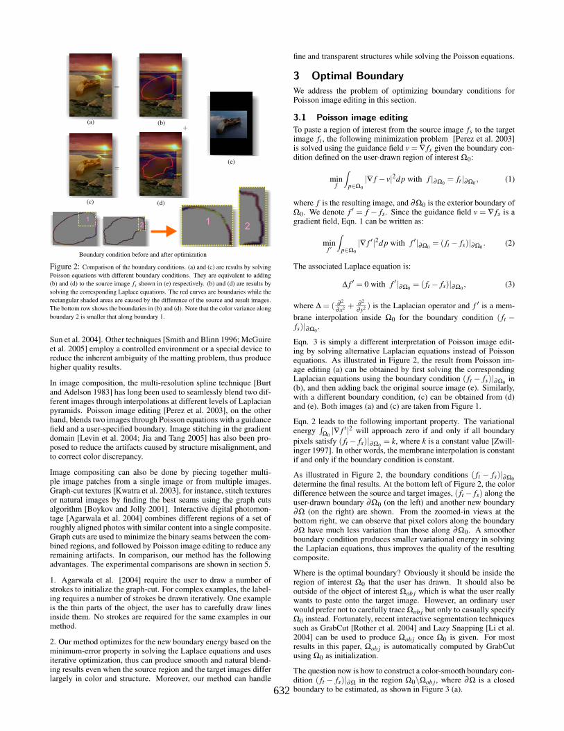
(a) (b)Figure 3: Boundary optimization. (a) The region of interest Ω0 is pasted onto thetarget image, which completely encloses the object of interest Ωob j . The optimizedboundary ∂Ω lies inside Ω0\Ωob j . The cut C is shown in red. (b) Zoom-in view ofthe cut C. The yellow and blue pixels are on different sides of C. The dashed yellowpixel p is adjacent to two blue pixels. Two shortest paths, shown as blue lines, aresimultaneously computed.
3.2 Boundary energy minimization
The optimized boundary ∂Ω should lie in between Ω0 and Ωob j .To reduce the color variance along the boundary, the following ob-jective function or boundary energy is minimized:
E(∂Ω,k) = ∑p∈∂Ω
(( ft(p)− fs(p))− k)2, s.t. Ωob j ⊂ Ω ⊂ Ω0, (4)
where k is a constant value to be determined. Note that in all our ex-periments, we take the value of each color pixel f (p) as a ternary setin r,g,b color space. ( f (p)− f (q)) is computed as the L2-normin color spaces. ( ft(p)− fs(p))− k represents the color deviationof the boundary pixels with respect to k.
Iterative optimization Since the optimal boundary may passthrough all pixels in Ω0\Ωob j , simultaneously estimating the op-timal k and the boundary ∂Ω is intractable. In the following, wepropose an iterative optimization algorithm to optimize them.
1. Initialize Ω as Ω0.
2. Given the current boundary ∂Ω, the optimal k is computed bytaking the derivative of Eqn. (4) and setting it to zero:
∂E(∂Ω,k)∂k = 0
⇔ k = 1|∂Ω| ∑p∈∂Ω( ft(p)− fs(p)), (5)
where |∂Ω| is the length of the boundary ∂Ω. So k is theaverage color difference on the boundary.
3. Given the current k, we optimize the boundary ∂Ω.
4. Repeat steps 2 and 3 until the energy of Eqn. 4 does not de-crease in two successive iterations.
The convergence of the above algorithm is guaranteed in step 4by constraining the energy defined in Eqn. 4 to be monotonicallydecreasing.
In step 3, computing an optimal boundary is equivalent to finding ashortest path in a graph G defined in Ω0\Ωob j (in short, the band).
3.3 A shortest closed-path algorithm
The nodes in G are pixels within the band while the edges represent4-connectivity relationships between neighboring pixels. The cost(( ft(p)− fs(p))− k)2 is defined on each node as the color differ-ence with respect to k. The accumulated cost of a path sums upthe costs of all nodes on the path. For a single object, the estimatedΩob j in our method can be regarded as genus-0 region and Ω0\Ωob jis of genus-1 type, as shown in Figure 3 (a).
Unlike a standard shortest path problem, ∂Ω is a closed curveenclosing Ωob j , which complicates the optimization. To make ittractable, we first change the type of region Ω0\Ωob j from genus-1 to genus-0. This can be done by breaking the band connectivityusing a cut C, as shown in red in Figure 3 (a). In the correspondingrepresentation in graph G , we remove all edges crossing the cut.In the following, we show how to compute a closed shortest-pathusing 2D dynamic programming.
A shortest closed-path algorithm• As illustrated in Figure 3(b), for each pixel p on one side of
the cut C (shown in yellow), we compute the shortest pathsto all adjacent pixels on the other side of the cut (shown inblue). Since graph G is a 2D grid, computing the shortestpath from any node to all others in the band can be achievedby 2D dynamic programming [Dijkstra 1959; Mortensen andBarrett 1995] with a complexity O(N), where N is the numberof pixels in the band. Among all the shortest paths startingfrom pixel p and ending at the neighboring pixels on the otherside of the cut, Path(p) is the one with minimum cost. InFigure 3(b), for two dashed blue pixels that are neighbors top in the image plane, their corresponding shortest paths arecomputed and shown as blue lines.
• We repeat the previous computation for all pixels on the yel-low side of the cut C, and get a set of Path. The optimizedboundary ∂Ω is assigned as one that gives the globally mini-mum cost. Suppose that there are M pixels on the yellow sideof the cut in graph G , the overall computational complexity isO(MN).
If the optimal boundary passes the cut C only once, the above algo-rithm will reach the global minimum of the energy defined in Eqn.4. Indeed, the path with the minimum accumulated cost seldomtwists in our experiments.
The cut C intersects the band at two pixels on ∂Ω0 and ∂Ωob j re-spectively. There are many possibilities how it is initialized. Inour method, to achieve better performance, we compute a shorteststraight line segment among all pixel pairs connecting ∂Ωob j and∂Ω0 by computing the Euclidian distance. This line segment isthen rasterized into a pixel list in a 2D image plane. The cut C isdrawn adjacent to the pixel list on any side. There are two bene-fits in computing the shortest cut C. First, the short length reducesthe probability that the optimal boundary passes the cut more thanonce. Second, with fewer pixels adjacent to the cut C, the value ofM will be small, which speeds up the computation.
4 Fractional boundary
An optimized boundary condition reduces the variational energyin solving the Laplacian equations, and avoids unnatural blurringin the composite. However, the optimized boundary may intersectwith the object with a fractional boundary and break up subtle andfine details. Figure 4 depicts a scenario where ∂Ω is close to ∂Ωob jand breaks the hairy structures (shown in (c) and (d)). To faith-fully preserve the object’s transparent boundary, we propose to in-corporate an alpha matte in a blended guidance field for Poissonequations, by detecting the regions where alpha blending should beapplied along the boundary.
4.1 A blended guidance field
Our goal of introducing transparency is to preserve precise frac-tional boundary of the object of interest from the source imagewhen it is composited onto the target image while being capable ofblending the color of the object seamlessly with the target image.Conventional alpha blending techniques cannot modify the color ofthe source object. To combine alpha blending with Poisson imageediting, we define a binary coverage mask M to indicate where al-pha blending should be applied (M(p) = 1) and vice versa, which
633
PSfrag replacements(a) (b) (c)
(d)
(d)
(e) (f)
∂Ωob j∂Ωob j ∂Ω0 ∂Ω
∂Ω∩∂Ωob j
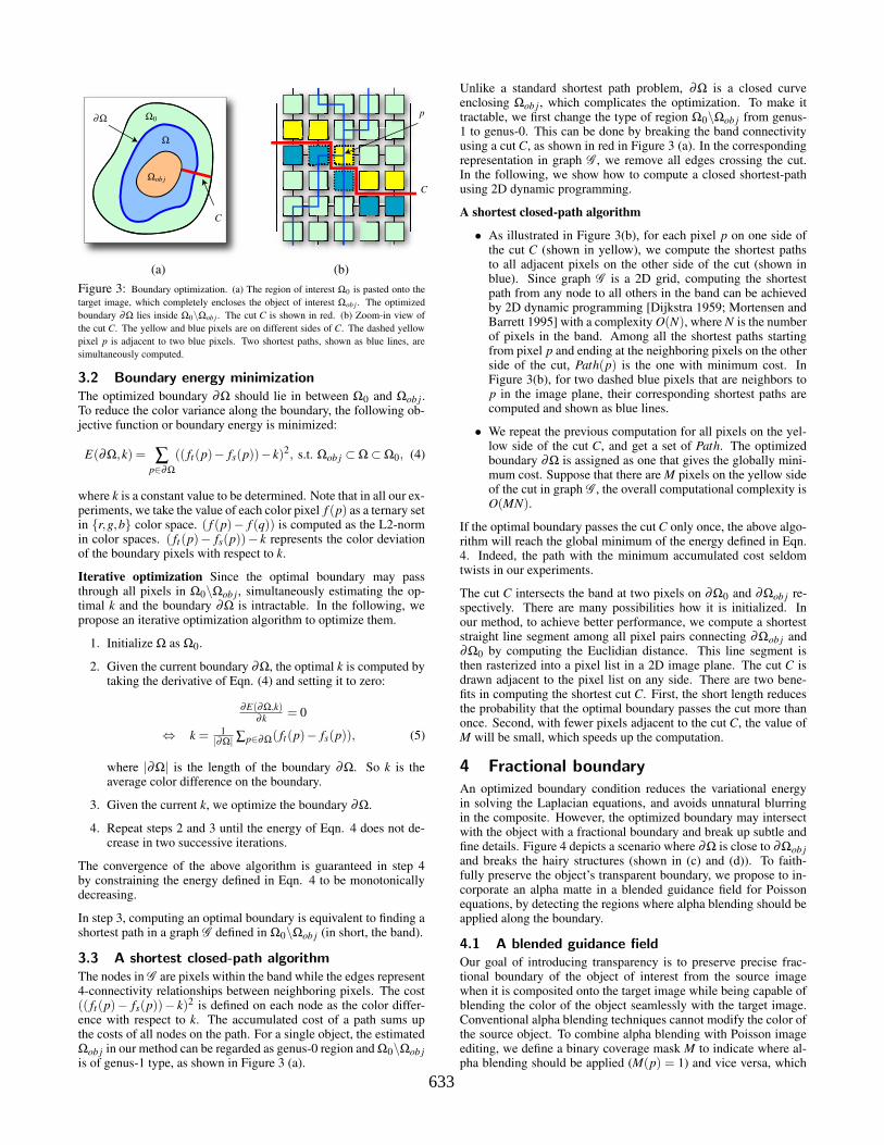
Figure 4: Preserving fractional object boundary. Given the input source image ofa flower in (a) and target image in (b), the optimized boundary ∂Ω snaps closely tothe top of the flower’s silhouette ∂Ωob j , thus intersects the fine details as shown in(c). Using the optimized boundary to solve the Poisson equation, as shown in (d),the fractional boundary cannot be well preserved as depicted in the zoom-in view (e).Our approach integrates the object’s alpha matte in the Poisson equation, and faithfullypreserves the fine details and produces an improved composite of the flower shown in(f). The corresponding zoom-in view is shown in (e).
partitions the image into regions. However, when directly apply-ing the blending techniques in separate regions, the pixels in ad-jacent region boundaries may have color discontinuities since theyare processed by two methods respectively without an appropriatespatial transition. To eliminate the artifact caused by the color dis-continuity, we integrate the alpha matte in the blended guidancefield in the Poisson equation.
We denote Φ = p|0 < α(p) < 1 as the fractional object boundary,where α is computed automatically within a few pixels surround-ing Ωob j by coherence matting [Shum et al. 2004]. Comparing toBayesian matting, coherence matting cooperates a prior of the alphavalue in its formulation. In our method, we model it as a Gaussiandistribution with respect to the median axis of Φ. Taking Figure5(b) as an illustration, Φ is of the shape of a narrow blue belt. Theblended guidance field is v′ = (v′x,v′y). For each pixel p = (x,y),v′x(x,y) is defined as:
v′x(x,y) =
∇x fs(x,y) M(x,y) = M(x+1,y) = 0∇x(α fs +(1−α) ft) M(x,y) = M(x+1,y) = 1
0 M(x,y) 6= M(x+1,y)(6)
v′y(x,y) is defined in a similar way. It shows that, depending onwhether the alpha matte is applied, v′x(x,y) is defined as the alphablended gradient or source image gradient in regions M = 1 andM = 0 respectively. However, in between these two regions, thegradient has no exact definition in image space. So we assign valuezero to these pixel gradients to smoothly fuse the two regions andeliminate color discontinuity.
Given the new blended guidance field, we minimize the followingvariational energy:
argminf
∫
p∈Ω∪Φ||∇ f − v′||2d p with f |∂ (Ω∪Φ) = ft |∂ (Ω∪Φ), (7)
where Ω∪Φ includes pixels either within the optimized boundaryor inside the fractional object boundary, and ∂ (Ω∪Φ) is Ω∪Φ’sexterior boundary.
Based on the above analysis, to solve the boundary problem, weconstruct the binary coverage mask M within Ω∪Φ before solvingEqn. 7. Consider the pixels inside the object where α(p) = 1,the guidance field v′ will always be ∇ fs regardless of the values ofM(p). Therefore, we do not need to compute M in these pixels.
PSfrag replacements
1
1
2
2
Φ
∂Ω
pq
M(p) = 0
M(p) = 1
(a) (b)
(c) (d)
Figure 5: Construction of the binary coverage mask M. (a) A source object withfractional boundary is pasted onto a target image. The dashed curve is the optimizedboundary ∂Ω. (b) The blue belt shows the region Φ = p|0 < α(p) < 1. As indicatedby arrows 1 and 2, ∂Ω penetrates into the belt where matte compositing should beapplied. (c) Zoom-in views of segments 1 and 2, around which the region p|M(p) =
1 is computed. (d) The resulting binary coverage mask where p|M(p) = 0 andp|M(p) = 1 are shown in yellow and green.
Figure 5 illustrates how we estimate M. In Figures 5(a) and 5(b),∂Ω penetrates into the fractional object boundary in two segments1 and 2, where some pixels with fractional alpha value are left out-side Ω. This breaks the structure of the object boundary. Aroundsegments 1 and 2, matte compositing is applied in the blended guid-ance field and M is set to 1. In the following, we list the main stepsto construct the mask M:
• We first compute the head and tail intersections between ∂Ωand the belt Φ in each segment, indicated as red dots in (c).Two segments that contain the intersections are indicated byarrows 1 and 2 in Figures 5(b) and 5(c).
• To get the region where alpha blending should be applied, wecompute the nearest points on the other side of the belt Φ,as shown by the yellow points, and connect the correspondingred and yellow points by straight line segments. Thus, the beltΦ is partitioned into blue and green in Figure 5(c).
• We set the green region in Figure 5(d) as p|M(p) = 1, andset M(p) = 0 for the remaining pixels p in Ω∪Φ.
5 Experimental Results
We apply drag-and-drop pasting on a wide variety of source andtarget images, and compare it with Poisson image editing, mattecompositing, and digital photomontage. The results are automati-cally computed by applying boundary optimization and the blendedguidance field consecutively.
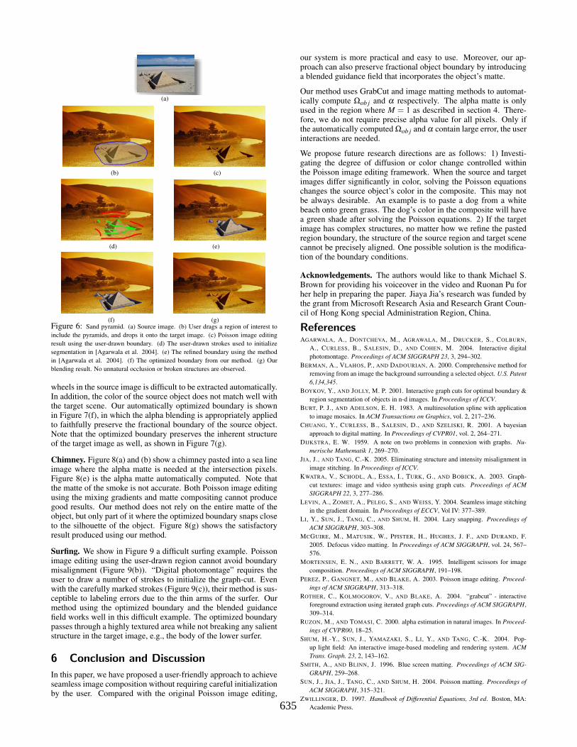
Sand pyramid. If the source and target images vary significantly incolor and structure, as shown in Figures 6(a) and (b), Poisson imageediting method cannot produce satisfactory results (Figure 6(c)).When applying “digital photomontage” [Agarwala et al. 2004] us-ing the user-drawn strokes in Figure 6(d), the result still does notfaithfully preserve the object structures (Figure 6(e)). Our approachcomputes an optimized boundary around the sand pyramid (Figure6(f)). No blurring, color mismatches or broken structures are pro-duced (Figure 6(g)), even though the top of the pyramid intersectswith the river in the target image.
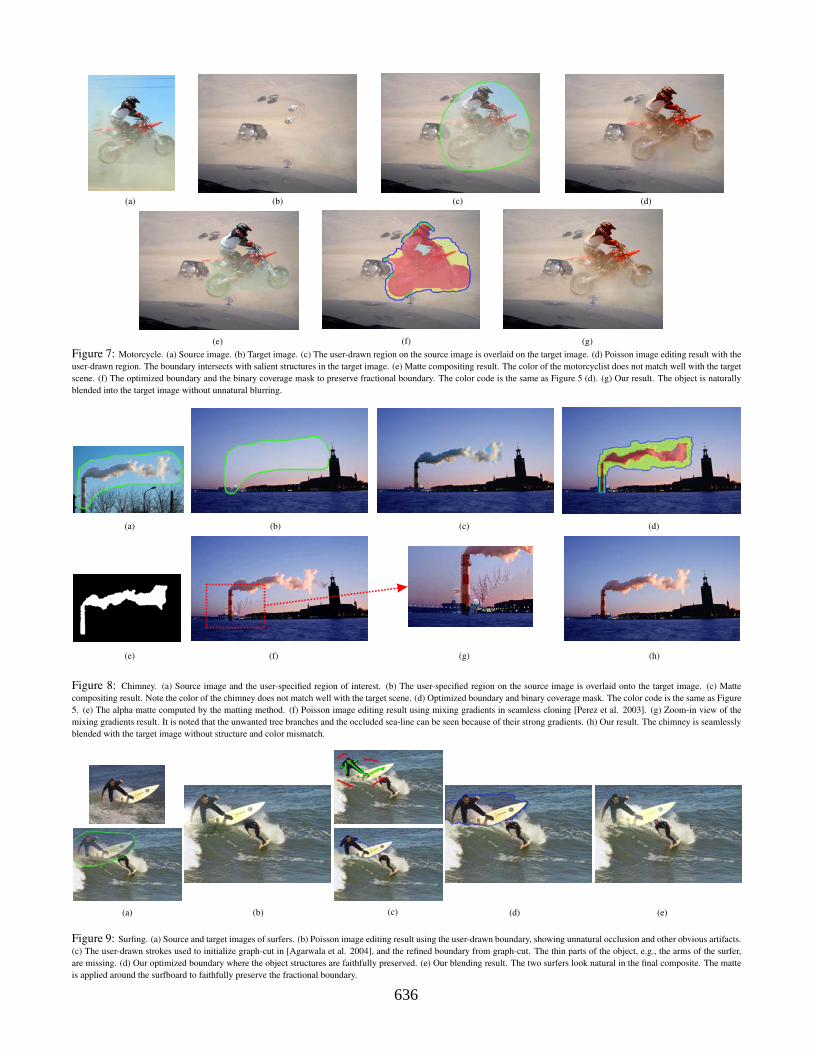
Motorcycle. In Figure 7, the pasted motorcycle touches the carsand the Toyota sign in the target image. Figure 7(d) shows the re-sult using Poisson image editing with a user-drawn boundary. It isnot surprising that the result looks unnatural, because the pasted re-gion does not match well with the target image. Figure 7(e) is thematte compositing result. Note that the alpha matte between the two
634
PSfrag replacements
(a)
(b) (c)
(d) (e)
(f) (g)Figure 6: Sand pyramid. (a) Source image. (b) User drags a region of interest toinclude the pyramids, and drops it onto the target image. (c) Poisson image editingresult using the user-drawn boundary. (d) The user-drawn strokes used to initializesegmentation in [Agarwala et al. 2004]. (e) The refined boundary using the methodin [Agarwala et al. 2004]. (f) The optimized boundary from our method. (g) Ourblending result. No unnatural occlusion or broken structures are observed.
wheels in the source image is difficult to be extracted automatically.In addition, the color of the source object does not match well withthe target scene. Our automatically optimized boundary is shownin Figure 7(f), in which the alpha blending is appropriately appliedto faithfully preserve the fractional boundary of the source object.Note that the optimized boundary preserves the inherent structureof the target image as well, as shown in Figure 7(g).
Chimney. Figure 8(a) and (b) show a chimney pasted into a sea lineimage where the alpha matte is needed at the intersection pixels.Figure 8(e) is the alpha matte automatically computed. Note thatthe matte of the smoke is not accurate. Both Poisson image editingusing the mixing gradients and matte compositing cannot producegood results. Our method does not rely on the entire matte of theobject, but only part of it where the optimized boundary snaps closeto the silhouette of the object. Figure 8(g) shows the satisfactoryresult produced using our method.
Surfing. We show in Figure 9 a difficult surfing example. Poissonimage editing using the user-drawn region cannot avoid boundarymisalignment (Figure 9(b)). “Digital photomontage” requires theuser to draw a number of strokes to initialize the graph-cut. Evenwith the carefully marked strokes (Figure 9(c)), their method is sus-ceptible to labeling errors due to the thin arms of the surfer. Ourmethod using the optimized boundary and the blended guidancefield works well in this difficult example. The optimized boundarypasses through a highly textured area while not breaking any salientstructure in the target image, e.g., the body of the lower surfer.
6 Conclusion and Discussion
In this paper, we have proposed a user-friendly approach to achieveseamless image composition without requiring careful initializationby the user. Compared with the original Poisson image editing,
our system is more practical and easy to use. Moreover, our ap-proach can also preserve fractional object boundary by introducinga blended guidance field that incorporates the object’s matte.
Our method uses GrabCut and image matting methods to automat-ically compute Ωob j and α respectively. The alpha matte is onlyused in the region where M = 1 as described in section 4. There-fore, we do not require precise alpha value for all pixels. Only ifthe automatically computed Ωob j and α contain large error, the userinteractions are needed.
We propose future research directions are as follows: 1) Investi-gating the degree of diffusion or color change controlled withinthe Poisson image editing framework. When the source and targetimages differ significantly in color, solving the Poisson equationschanges the source object’s color in the composite. This may notbe always desirable. An example is to paste a dog from a whitebeach onto green grass. The dog’s color in the composite will havea green shade after solving the Poisson equations. 2) If the targetimage has complex structures, no matter how we refine the pastedregion boundary, the structure of the source region and target scenecannot be precisely aligned. One possible solution is the modifica-tion of the boundary conditions.
Acknowledgements. The authors would like to thank Michael S.Brown for providing his voiceover in the video and Ruonan Pu forher help in preparing the paper. Jiaya Jia’s research was funded bythe grant from Microsoft Research Asia and Research Grant Coun-cil of Hong Kong special Administration Region, China.
ReferencesAGARWALA, A., DONTCHEVA, M., AGRAWALA, M., DRUCKER, S., COLBURN,
A., CURLESS, B., SALESIN, D., AND COHEN, M. 2004. Interactive digitalphotomontage. Proceedings of ACM SIGGRAPH 23, 3, 294–302.
BERMAN, A., VLAHOS, P., AND DADOURIAN, A. 2000. Comprehensive method forremoving from an image the background surrounding a selected object. U.S. Patent6,134,345.
BOYKOV, Y., AND JOLLY, M. P. 2001. Interactive graph cuts for optimal boundary ®ion segmentation of objects in n-d images. In Proceedings of ICCV.
BURT, P. J., AND ADELSON, E. H. 1983. A multiresolution spline with applicationto image mosaics. In ACM Transactions on Graphics, vol. 2, 217–236.
CHUANG, Y., CURLESS, B., SALESIN, D., AND SZELISKI, R. 2001. A bayesianapproach to digital matting. In Proceedings of CVPR01, vol. 2, 264–271.
DIJKSTRA, E. W. 1959. A note on two problems in connexion with graphs. Nu-merische Mathematik 1, 269–270.
JIA, J., AND TANG, C.-K. 2005. Eliminating structure and intensity misalignment inimage stitching. In Proceedings of ICCV.
KWATRA, V., SCHODL, A., ESSA, I., TURK, G., AND BOBICK, A. 2003. Graph-cut textures: image and video synthesis using graph cuts. Proceedings of ACMSIGGRAPH 22, 3, 277–286.
LEVIN, A., ZOMET, A., PELEG, S., AND WEISS, Y. 2004. Seamless image stitchingin the gradient domain. In Proceedings of ECCV, Vol IV: 377–389.
LI, Y., SUN, J., TANG, C., AND SHUM, H. 2004. Lazy snapping. Proceedings ofACM SIGGRAPH, 303–308.
MCGUIRE, M., MATUSIK, W., PFISTER, H., HUGHES, J. F., AND DURAND, F.2005. Defocus video matting. In Proceedings of ACM SIGGRAPH, vol. 24, 567–576.
MORTENSEN, E. N., AND BARRETT, W. A. 1995. Intelligent scissors for imagecomposition. Proceedings of ACM SIGGRAPH, 191–198.
PEREZ, P., GANGNET, M., AND BLAKE, A. 2003. Poisson image editing. Proceed-ings of ACM SIGGRAPH, 313–318.
ROTHER, C., KOLMOGOROV, V., AND BLAKE, A. 2004. “grabcut” - interactiveforeground extraction using iterated graph cuts. Proceedings of ACM SIGGRAPH,309–314.
RUZON, M., AND TOMASI, C. 2000. alpha estimation in natural images. In Proceed-ings of CVPR00, 18–25.
SHUM, H.-Y., SUN, J., YAMAZAKI, S., LI, Y., AND TANG, C.-K. 2004. Pop-up light field: An interactive image-based modeling and rendering system. ACMTrans. Graph. 23, 2, 143–162.
SMITH, A., AND BLINN, J. 1996. Blue screen matting. Proceedings of ACM SIG-GRAPH, 259–268.
SUN, J., JIA, J., TANG, C., AND SHUM, H. 2004. Poisson matting. Proceedings ofACM SIGGRAPH, 315–321.
ZWILLINGER, D. 1997. Handbook of Differential Equations, 3rd ed. Boston, MA:Academic Press.635
PSfrag replacements
(a) (b) (c) (d)
(e) (f) (g)Figure 7: Motorcycle. (a) Source image. (b) Target image. (c) The user-drawn region on the source image is overlaid on the target image. (d) Poisson image editing result with theuser-drawn region. The boundary intersects with salient structures in the target image. (e) Matte compositing result. The color of the motorcyclist does not match well with the targetscene. (f) The optimized boundary and the binary coverage mask to preserve fractional boundary. The color code is the same as Figure 5 (d). (g) Our result. The object is naturallyblended into the target image without unnatural blurring.
PSfrag replacements(a)(b)(c)(d)(e)(f)(g)
(a) (b) (c) (d)
(e) (f) (g) (h)
Figure 8: Chimney. (a) Source image and the user-specified region of interest. (b) The user-specified region on the source image is overlaid onto the target image. (c) Mattecompositing result. Note the color of the chimney does not match well with the target scene. (d) Optimized boundary and binary coverage mask. The color code is the same as Figure5. (e) The alpha matte computed by the matting method. (f) Poisson image editing result using mixing gradients in seamless cloning [Perez et al. 2003]. (g) Zoom-in view of themixing gradients result. It is noted that the unwanted tree branches and the occluded sea-line can be seen because of their strong gradients. (h) Our result. The chimney is seamlesslyblended with the target image without structure and color mismatch.
PSfrag replacements(a)(b)(c)(d)(e)(f)(g)(a)(b)(c)(d)
(e)
(f)(g)(h)
(a) (b) (c) (d)
Figure 9: Surfing. (a) Source and target images of surfers. (b) Poisson image editing result using the user-drawn boundary, showing unnatural occlusion and other obvious artifacts.(c) The user-drawn strokes used to initialize graph-cut in [Agarwala et al. 2004], and the refined boundary from graph-cut. The thin parts of the object, e.g., the arms of the surfer,are missing. (d) Our optimized boundary where the object structures are faithfully preserved. (e) Our blending result. The two surfers look natural in the final composite. The matteis applied around the surfboard to faithfully preserve the fractional boundary.
636