Draft ETSI EN 303 454 V1.1 - gncc.ge · ETSI 2 Draft ETSI EN 303 454 V1.1.0 (2017-03) Reference...
25
Draft ETSI EN 303 454 V1.1.0 (2017-03) Short Range Devices (SRD); Metal and object detection sensors in the frequency range 1 kHz to 148,5 kHz; Harmonised standard covering the essential requirements of article 3.2 of Directive 2014/53/EU HARMONISED EUROPEAN STANDARD
Transcript of Draft ETSI EN 303 454 V1.1 - gncc.ge · ETSI 2 Draft ETSI EN 303 454 V1.1.0 (2017-03) Reference...

Draft ETSI EN 303 454 V1.1.0 (2017-03)
Short Range Devices (SRD); Metal and object detection sensors
in the frequency range 1 kHz to 148,5 kHz; Harmonised standard covering the essential requirements
of article 3.2 of Directive 2014/53/EU
HARMONISED EUROPEAN STANDARD

ETSI
Draft ETSI EN 303 454 V1.1.0 (2017-03) 2
Reference DEN/ERM-TG28-542
Keywords harmonised standard, inductive, measurement,
SRD
ETSI
650 Route des Lucioles F-06921 Sophia Antipolis Cedex - FRANCE
Tel.: +33 4 92 94 42 00 Fax: +33 4 93 65 47 16
Siret N° 348 623 562 00017 - NAF 742 C
Association à but non lucratif enregistrée à la Sous-Préfecture de Grasse (06) N° 7803/88
Important notice
The present document can be downloaded from: http://www.etsi.org/standards-search
The present document may be made available in electronic versions and/or in print. The content of any electronic and/or print versions of the present document shall not be modified without the prior written authorization of ETSI. In case of any
existing or perceived difference in contents between such versions and/or in print, the only prevailing document is the print of the Portable Document Format (PDF) version kept on a specific network drive within ETSI Secretariat.
Users of the present document should be aware that the document may be subject to revision or change of status. Information on the current status of this and other ETSI documents is available at
https://portal.etsi.org/TB/ETSIDeliverableStatus.aspx
If you find errors in the present document, please send your comment to one of the following services: https://portal.etsi.org/People/CommiteeSupportStaff.aspx
Copyright Notification
No part may be reproduced or utilized in any form or by any means, electronic or mechanical, including photocopying and microfilm except as authorized by written permission of ETSI.
The content of the PDF version shall not be modified without the written authorization of ETSI. The copyright and the foregoing restriction extend to reproduction in all media.
© European Telecommunications Standards Institute 2017.
All rights reserved.
DECTTM, PLUGTESTSTM, UMTSTM and the ETSI logo are Trade Marks of ETSI registered for the benefit of its Members. 3GPPTM and LTE™ are Trade Marks of ETSI registered for the benefit of its Members and
of the 3GPP Organizational Partners. GSM® and the GSM logo are Trade Marks registered and owned by the GSM Association.

ETSI
Draft ETSI EN 303 454 V1.1.0 (2017-03) 3
Contents
Intellectual Property Rights ................................................................................................................................ 5
Foreword ............................................................................................................................................................. 5
Modal verbs terminology .................................................................................................................................... 5
Introduction ........................................................................................................................................................ 5
1 Scope ........................................................................................................................................................ 7
2 References ................................................................................................................................................ 7
2.1 Normative references ......................................................................................................................................... 7
2.2 Informative references ........................................................................................................................................ 7
3 Definitions, symbols and abbreviations ................................................................................................... 8
3.1 Definitions .......................................................................................................................................................... 8
3.2 Symbols .............................................................................................................................................................. 9
3.3 Abbreviations ..................................................................................................................................................... 9
4 Technical requirements specifications ..................................................................................................... 9
4.1 Environmental conditions ................................................................................................................................... 9
4.2 General ............................................................................................................................................................. 10
4.2.1 Wanted performance criteria....................................................................................................................... 10
4.2.2 Operational Modes ...................................................................................................................................... 10
4.2.3 Presentation of equipment for testing purposes .......................................................................................... 10
4.3 Transmitter conformance requirements ............................................................................................................ 11
4.3.1 Operating Frequency Range (OFR) ............................................................................................................ 11
4.3.1.1 Applicability.......................................................................................................................................... 11
4.3.1.2 Description ............................................................................................................................................ 11
4.3.1.3 Limits .................................................................................................................................................... 11
4.3.1.4 Conformance ......................................................................................................................................... 12
4.3.2 Transmitter H-field requirements ............................................................................................................... 12
4.3.2.1 Applicability.......................................................................................................................................... 12
4.3.2.2 Description ............................................................................................................................................ 12
4.3.2.3 Limits .................................................................................................................................................... 12
4.3.2.4 Conformance ......................................................................................................................................... 13
4.3.3 Transmitter E-field requirements ................................................................................................................ 13
4.3.3.1 Applicability.......................................................................................................................................... 13
4.3.3.2 Description ............................................................................................................................................ 13
4.3.3.3 Limits .................................................................................................................................................... 13
4.3.3.4 Conformance ......................................................................................................................................... 13
4.3.4 Transmitter spurious emissions ................................................................................................................... 13
4.3.4.1 Applicability.......................................................................................................................................... 13
4.3.4.2 Description ............................................................................................................................................ 14
4.3.4.3 Limits .................................................................................................................................................... 15
4.3.4.4 Conformance ......................................................................................................................................... 15
4.3.5 Transmitter out of band (OOB) emissions .................................................................................................. 15
4.3.5.1 Applicability.......................................................................................................................................... 15
4.3.5.2 Description ............................................................................................................................................ 15
4.3.5.3 Limits .................................................................................................................................................... 15
4.3.5.4 Conformance ......................................................................................................................................... 16
4.4 Receiver Conformance requirements ............................................................................................................... 16
4.4.1 Introduction................................................................................................................................................. 16
4.4.2 Receiver spurious emissions ....................................................................................................................... 16
4.4.3 Receiver blocking ....................................................................................................................................... 16
4.4.3.1 Applicability.......................................................................................................................................... 16
4.4.3.2 Description ............................................................................................................................................ 16
4.4.3.3 Limits .................................................................................................................................................... 16
4.4.3.4 Conformance ......................................................................................................................................... 17
5 Testing for compliance with technical requirements .............................................................................. 17

ETSI
Draft ETSI EN 303 454 V1.1.0 (2017-03) 4
5.1 Environmental conditions for testing ............................................................................................................... 17
5.2 General conditions for testing .......................................................................................................................... 17
5.2.1 Product information .................................................................................................................................... 17
5.3 Normal and extreme test conditions ................................................................................................................. 17
5.4 Test sites and general arrangements for radiated measurements ...................................................................... 17
5.5 Measuring receiver ........................................................................................................................................... 18
5.6 Measurement uncertainty ................................................................................................................................. 18
5.7 Interpretation of the measurement results ........................................................................................................ 18
6 Conformance methods of measurement for transmitters and receivers ................................................. 18
6.1 General ............................................................................................................................................................. 18
6.2 Transmitter conformance methods ................................................................................................................... 19
6.2.1 OFR ............................................................................................................................................................ 19
6.2.2 H-field ......................................................................................................................................................... 20
6.2.3 Transmitter unwanted emissions ................................................................................................................. 20
6.2.4 Transmitter radiated E-field ........................................................................................................................ 20
6.3 Receiver conformance methods ....................................................................................................................... 20
6.3.1 Receiver spurious emissions ....................................................................................................................... 20
6.3.2 Receiver blocking ....................................................................................................................................... 21
Annex A (informative): Relationship between the present document and the essential requirements of Directive 2014/53/EU ......................................................... 23
Annex B (informative): Change history ............................................................................................... 24
History .............................................................................................................................................................. 25

ETSI
Draft ETSI EN 303 454 V1.1.0 (2017-03) 5
Intellectual Property Rights IPRs essential or potentially essential to the present document may have been declared to ETSI. The information pertaining to these essential IPRs, if any, is publicly available for ETSI members and non-members, and can be found in ETSI SR 000 314: "Intellectual Property Rights (IPRs); Essential, or potentially Essential, IPRs notified to ETSI in respect of ETSI standards", which is available from the ETSI Secretariat. Latest updates are available on the ETSI Web server (https://ipr.etsi.org/).
Pursuant to the ETSI IPR Policy, no investigation, including IPR searches, has been carried out by ETSI. No guarantee can be given as to the existence of other IPRs not referenced in ETSI SR 000 314 (or the updates on the ETSI Web server) which are, or may be, or may become, essential to the present document.
Foreword This draft Harmonised European Standard (EN) has been produced by ETSI Technical Committee Electromagnetic compatibility and Radio spectrum Matters (ERM), and is now submitted for the combined Public Enquiry and Vote phase of the ETSI standards EN Approval Procedure.
The present document has been prepared under the Commission's standardisation request C(2015) 5376 final [i.6] to provide one voluntary means of conforming to the essential requirements of Directive 2014/53/EU on the harmonisation of the laws of the Member States relating to the making available on the market of radio equipment and repealing Directive 1999/5/EC [i.3].
Once the present document is cited in the Official Journal of the European Union under that Directive, compliance with the normative clauses of the present document given in table A.1 confers, within the limits of the scope of the present document, a presumption of conformity with the corresponding essential requirements of that Directive, and associated EFTA regulations.
Proposed national transposition dates
Date of latest announcement of this EN (doa): 3 months after ETSI publication
Date of latest publication of new National Standard or endorsement of this EN (dop/e):
6 months after doa
Date of withdrawal of any conflicting National Standard (dow): 18 months after doa
Modal verbs terminology In the present document "shall", "shall not", "should", "should not", "may", "need not", "will", "will not", "can" and "cannot" are to be interpreted as described in clause 3.2 of the ETSI Drafting Rules (Verbal forms for the expression of provisions).
"must" and "must not" are NOT allowed in ETSI deliverables except when used in direct citation.
Introduction The present document covers metal and object detection sensors in the frequency range 1 kHz to 148,5 kHz
The present document is structured as follows:
• Clauses 1 through 3 provide a general description on the types of equipment covered by the present document and the definitions, symbols and abbreviations used.
• Clause 4 provides the technical requirements specifications, limits and conformance relative to transmitter and receiver.
ETSI
Draft ETSI EN 303 454 V1.1.0 (2017-03) 6
• Clauses 5 specifies the conditions for testing of the equipment and interpretation of the measurement results with the maximum measurement uncertainty values.
• Clause 6 specifies the required measurement methods.
• Annex A (informative) provides the relationship between the present document and the essential requirements of Directive 2014/53/EU [i.3].

ETSI
Draft ETSI EN 303 454 V1.1.0 (2017-03) 7
1 Scope The present document specifies technical characteristics and methods of measurements for metal and object detection sensors (including e.g. inductive proximity sensors, inductive cable detectors) in the frequency range 1 kHz to 148,5 kHz.
The present document covers the essential requirements of article 3.2 of Directive 2014/53/EU [i.3] under the conditions identified in annex A.
The size for the inductive loops covered by the present document is limited to 3 m2.
The present document does not cover other devices using the frequency range below 148,5 kHz, e.g. ETSI EN 303 348 [i.7] (Inductive loop for hearing impaired in 0 kHz to 20 kHz), ETSI EN 303 447 [i.8] (Inductive robotic mowers).
These radio equipment types are capable of operating in all or part of the frequency bands given in table 1.
Table 1: Permitted range of operation
Permitted range of operation Transmit 1 kHz to 148,5 kHz Receive 1 kHz to 148,5 kHz
NOTE: It should be noted that the frequency range between 9 kHz and 148,5 kHz is EU wide harmonised for inductive Short Range Devices according to Directive 2013/752/EU [i.2].
2 References
2.1 Normative references References are specific, identified by date of publication and/or edition number or version number. Only the cited version applies.
Referenced documents which are not found to be publicly available in the expected location might be found at https://docbox.etsi.org/Reference/.
NOTE: While any hyperlinks included in this clause were valid at the time of publication, ETSI cannot guarantee their long term validity.
The following referenced documents are necessary for the application of the present document.
[1] ETSI EN 300 330 (V2.1.1) (11-2016): "Short Range Devices (SRD); Radio equipment in the frequency range 9 kHz to 25 MHz and inductive loop systems in the frequency range 9 kHz to 30 MHz; Harmonised Standard covering the essential requirements of article 3.2 of the Directive 2014/53/EU".
2.2 Informative references References are either specific (identified by date of publication and/or edition number or version number) or non-specific. For specific references, only the cited version applies. For non-specific references, the latest version of the referenced document (including any amendments) applies.
NOTE: While any hyperlinks included in this clause were valid at the time of publication, ETSI cannot guarantee their long term validity.
The following referenced documents are not necessary for the application of the present document but they assist the user with regard to a particular subject area.
[i.1] CEPT/ERC Recommendation 70-03: "Relating to the use of Short Range Devices (SRD)".

ETSI
Draft ETSI EN 303 454 V1.1.0 (2017-03) 8
[i.2] EC Decision 2013/752/EU: "Commission implementing Decision of 11 December 2013 amending Decision 2006/771/EC on harmonisation of the radio spectrum for use by short-range devices and repealing Decision 2005/928/EC.
[i.3] Directive 2014/53/EU of the European Parliament and of the Council of 16 April 2014 on the harmonisation of the laws of the Member States relating to the making available on the market of radio equipment and repealing Directive 1999/5/EC.
[i.4] CEPT/ERC/REC 74-01: "Unwanted emissions in the spurious domain".
[i.5] ETSI EG 203 336: "Electromagnetic compatibility and Radio spectrum Matters (ERM); Guide for the selection of technical parameters for the production of Harmonised Standards covering article 3.1(b) and article 3.2 of Directive 2014/53/EU".
[i.6] Commission Implementing Decision C(2015) 5376 final of 4.8.2015 on a standardisation request to the European Committee for Electrotechnical Standardisation and to the European Telecommunications Standards Institute as regards radio equipment in support of Directive 2014/53/EU of the European Parliament and of the Council.
[i.7] ETSI EN 303 348: "Induction loop systems intended to assist the hearing impaired in the frequency range 10 Hz to 9 kHz; Harmonised Standard covering the essential requirements of article 3.2 of Directive 2014/53/EU".
[i.8] ETSI EN 303 447: "Short Range Devices (SRD); Inductive loop systems for robotic mowers in the frequency range 0 Hz to 148,5 kHz; Harmonised standard covering the essential requirements of article 3.2 of Directive for 2014/53/EU".
3 Definitions, symbols and abbreviations
3.1 Definitions For the purposes of the present document, the terms and definitions given in ETSI EN 300 330 [1] and the following apply:
99% OBW function: measurement function of a spectrum analyser
object detector: capacitive and inductive sensor which detects the presence of an object. Such detector partly also named as proximity sensor or proximity switch
Occupied BandWidth (OBW): width of a frequency band such that, below the lower and above the upper frequency limits, the mean powers emitted are each equal to 0,5 % of the total mean power of a given emission
NOTE: See figure 1.

ETSI
Draft ETSI EN 303 454 V1.1.0 (2017-03) 9
Figure 1: Occupied bandwidth (OBW)
3.2 Symbols For the purposes of the present document, the symbols given in ETSI EN 300 330 [1] and the following apply:
fc centre frequency of the OFR
fH highest frequency of the OFR
fL lowest frequency of the OFR
fsl frequency for the spurious emissions test (below fc) fsh frequency for the spurious emission test (above fc)
3.3 Abbreviations For the purposes of the present document, the abbreviations given in ETSI EN 300 330 [1] and the following apply:
OBW Occupied Bandwidth OFR Operating Frequency Range RR Radio Regulations
4 Technical requirements specifications
4.1 Environmental conditions The technical requirements of the present document apply under the environmental profile for operation of the equipment, which shall be declared by the manufacturer. The equipment shall comply with all the technical requirements of the present document which are identified as applicable in annex A at all times when operating within the boundary limits of the declared operational environmental profile. The conditions shall be used as descripted in clause 5.3.

ETSI
Draft ETSI EN 303 454 V1.1.0 (2017-03) 10
4.2 General
4.2.1 Wanted performance criteria
A metal and object detector is used to determine the presence of obscured objects made of conductive, magnetic, and/or dielectric materials such as non-ferrous metals, ferrous metals or wood. The objects are part of an environment, i.e. they are e.g. buried in the ground or embedded in building structures such as walls, floors, and ceilings.
The detection performance of the metal and object detector is measured in terms of the ability to detect objects from a specific set of objects in a specific set of environments up to a given maximum detection depth.
The manufacturer shall declare the specific set of objects, the specific set of environments, and the maximum detection depth for each of the relevant measurement modes.
Detection means the indication of any type of objects irrespective of its actual nature or consistency. I.e. that any classification of the object type by the EUT might be wrong as long as the EUT indicates the presence of an object.
The indications of objects by the EUT in the absence of objects are called false-positive indications.
For the purpose of the receiver performance tests, the EUT shall produce an appropriate output under normal conditions as indicated below:
• the objects in the specific set of objects, in the specific set of environments, up to the maximum detection are indicated and no false-positive indications are observed; or
• a degradation of the detection performance is indicated by the EUT as described in the manual.
The possibilities for the indication of the degradation of the detection performance include in particular:
• indication by a dedicated mean (e.g. specific light signal, specific tone signal, specific display content);
• indirect indication: the indicated detection result changes in short time intervals under otherwise stationary conditions.
4.2.2 Operational Modes
Metal and object detectors might have several operational modes:
• multiple measurement modes (one or several sensors switched on);
• non-measurement mode (sensors switched off).
The manufacturer shall declare the set of operational modes that are representative for the equipment.
The conformance measurements shall be performed in the representative set of operational modes.
Measurement modes might be specific but not limited to materials (e.g. metal, wooden studs), object properties (e.g. shape, diameter, depth), environments (e.g. concrete walls, dry walls), use case scenarios (e.g. finding, avoiding, tracing), sensitivities (e.g. high sensitivity, medium sensitivity, low sensitivity) or combinations thereof (e.g. universal mode).
The working principles of the sensors in the various modes might include continuous transmission (either stand-alone or in parallel) and intermittent transmission (either alternating or in parallel). The receivers of the sensors might be either switched on continuously or intermittent. In particular, receivers might at times be switched on while the respective transmitter is switched off (receiver only operation).
4.2.3 Presentation of equipment for testing purposes
Each EUT submitted for testing shall fulfil the requirements of the present document.
The manufacturer shall declare the range of operating conditions and power requirements as applicable, to establish the appropriate test conditions.

ETSI
Draft ETSI EN 303 454 V1.1.0 (2017-03) 11
Additionally, technical documentation and operating manuals, sufficient to make the test, shall be supplied.
Measurements shall be performed for all operational modes from clause 4.2.2 on samples of equipment defined in clause 4.2.2 of ETSI EN 300 330 [1].
4.3 Transmitter conformance requirements
4.3.1 Operating Frequency Range (OFR)
4.3.1.1 Applicability
This requirement applies to all EUT.
4.3.1.2 Description
The operating frequency range is the frequency range over which the EUT is intentionally transmitting. The operating frequency range of the EUT is determined by the lowest (f
L) and highest frequency (f
H) as occupied by the power
envelope.
The EUT could have more than one operating frequency range.
For a single frequency systems the OFR is equal to the occupied bandwidth (OBW) of the EUT.
For multi-frequency systems the OFR is described in figure 2.
Figure 2: OFR of a multi - frequency system
4.3.1.3 Limits
The operating frequency range shall be within the following limits:
• Upper edge of the operating frequency range: fH ≤ 148,5 kHz.
• Lower edge of the operating frequency range: fL ≥ 1 kHz.
For the later unwanted emission measurement procedure in clause 4.3.3.3 the OFR shall be calculated as: fH - fL and the
centre frequency as: �� =�����
�.
ETSI
Draft ETSI EN 303 454 V1.1.0 (2017-03) 12
4.3.1.4 Conformance
The conformance test suite for operational frequency range is provided in clause 6.1 and clause 6.2.1.
Conformance shall be established under test conditions to be declared by the manufacturer according to clause 4.1.
The interpretation of the results for the measurements uncertainty shall be as given in clause 5.7.
If the OFR cannot be measured based on the sensitivity level of the conformance test suite (defined in clause 6.1) the manufacturer shall declare the OFR.
4.3.2 Transmitter H-field requirements
4.3.2.1 Applicability
This requirement applies to all EUT.
4.3.2.2 Description
The radiated H-field is defined in the direction of maximum field strength of the EUT.
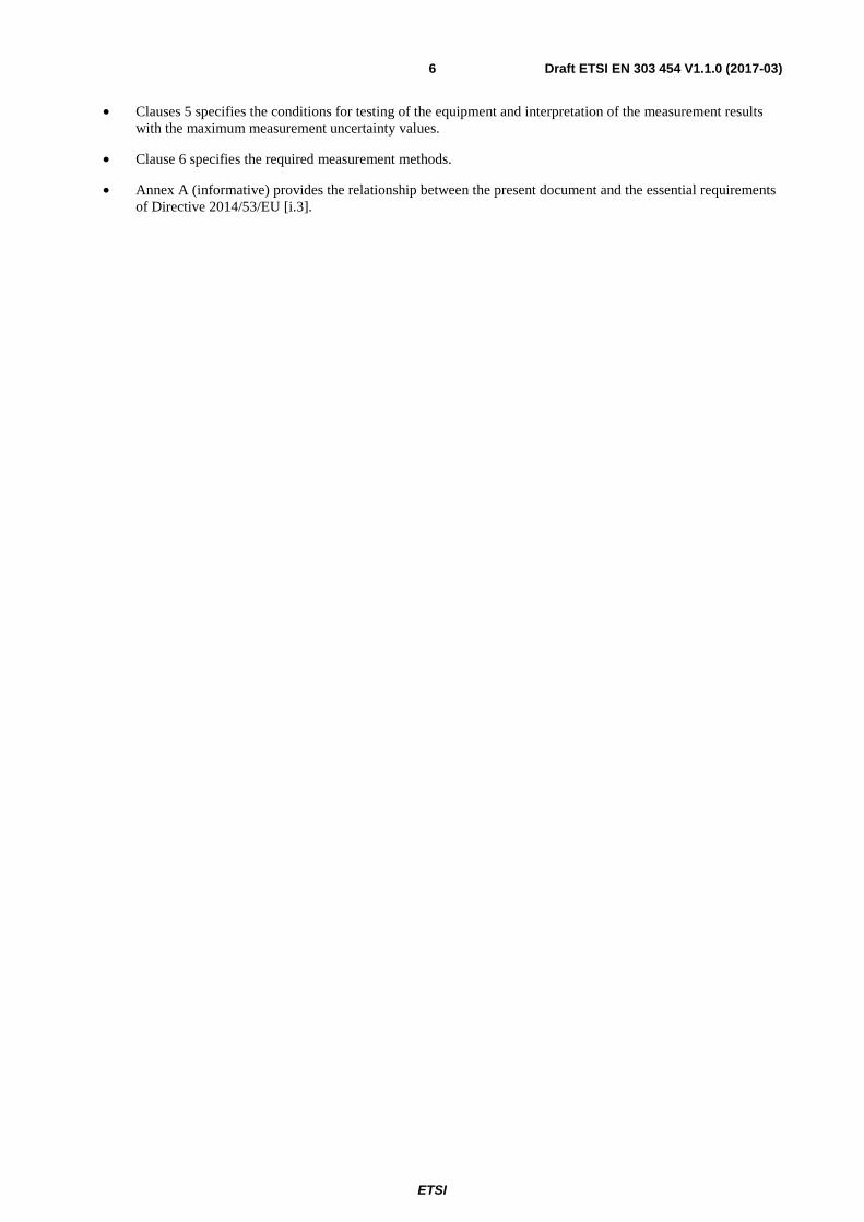
4.3.2.3 Limits
The H-field limits for the frequencies < 9 kHz are provided in table 2 and for the frequency range 9 kHz to 148,5 kHz in table 3.
The H-field limits in table 3 are EU wide harmonised for the SRD category "inductive devices" according to Decision 2013/752/EU [i.2]. Further information is available in CEPT/ERC/REC 70-03 [i.1].
For the frequency < 9 kHz no frequency usage conditions were known and available at the time of preparation of the present document. However, the H-field limits in table 2 are suggested to improve the intra- coexistence with other radio devices within this range.
Table 2: H-field limits below 9 kHz
Frequency range (kHz) H-field strength limit (Hf) dBμA/m at 10 m
1 ≤ f < 9 72
Table 3: H-field limits between 9 kHz and 148,5 kHz [i.2]
Frequency range (MHz) H-field strength limit (Hf) dBμA/m at 10 m
0,009 ≤ f < 0,090 72 descending 10 dB/dec above 0,03 MHz or according to note 1
(see note 2) 0,09 ≤ f < 0,119 42
0,119 ≤ f < 0,135 66 descending 10 dB/dec above 0,119 MHz or according to note 1
(see notes 2) 0,135 ≤ f < 0,140 42
0,140 ≤ f < 0,1485 37,7 NOTE 1: For the frequency ranges 9 kHz to 135 kHz, the following additional restrictions apply to limits
above 42 dBµA/m: - for loop coil antennas with an area between 0,05 m2 and 0,16 m2: the limit is: table
value + 10 × log (area/0,16 m2); - for loop coil antennas with an area < 0,05 m2 the limit is 10 dB below the table value
NOTE 2: Limit is 42 dBµA/m for the following spot frequencies: 60 kHz ± 250 Hz, 66,6 kHz ± 750 Hz, 75 kHz ± 250 Hz, 77,5 kHz ± 250 Hz, and 129,1 kHz ± 500 Hz.
NOTE 3: Calculation rules for limits at other measurement distances, see annex I of ETSI EN 300 330 [1].
ETSI
Draft ETSI EN 303 454 V1.1.0 (2017-03) 13
NOTE: Calculation rules for limits at other measurement distances, see annex I of ETSI EN 300 330 [1].
4.3.2.4 Conformance
The conformance test suite for transmitter H-field requirements is provided in clause 6.1 and clause 6.2.2.
Conformance shall be established under test conditions to be declared by the manufacturer according to clause 4.1.
The interpretation of the results for the measurements uncertainty shall be as given in clause 5.7.
If the transmitter H-Field radiation cannot be measured based on the sensitivity level of the conformance test suite (defined in clause 6.1) it can be assumed that the limits for the H-field requirements within tables 2 and 3 are fulfilled.
4.3.3 Transmitter E-field requirements
4.3.3.1 Applicability
The transmitter radiated E-field applies to E-Field Transmitter.
4.3.3.2 Description
The radiated E-field is defined as the E-field in the direction of maximum field strength under the specified conditions of measurement. This is defined for a transmitter with an integral antenna.
For a detailed explanation of the relationship between E-field and H-field, see ETSI EN 300 330 [1], annex G.
4.3.3.3 Limits
In the frequency range 1 kHz to 148,5 kHz, the limits of Hef
follow the H-fields limits, Hf, as given in clause 4.3.2.3,
tables 2 and 3 with an additional correction factor C. The correction factor C given below is specific for a 10 m measuring distance.
The limit Hef
= Hf + C;
where:
C = 20 × log (fc / 4,78 × 10⁶) dB;
and where:
fc is the carrier frequency in Hz.
For a graphical representation of the correction factor C see ETSI EN 300 330 [1], annex D.
4.3.3.4 Conformance
The conformance test suite for transmitter E-field requirements is provided in clause 6.1 and clause 6.2.4.
Conformance shall be established under test conditions to be declared by the manufacturer according to clause 4.1.
The interpretation of the results for the measurements uncertainty shall be as given in clause 5.7.
If the transmitter E-Field radiation cannot be measured based on the sensitivity level of the conformance test suite (defined in clause 6.1) it is assumed that the limits for the E-field requirements within tables 2 and 3 are fulfilled.
4.3.4 Transmitter spurious emissions
4.3.4.1 Applicability
This requirement applies to all EUT.

ETSI
Draft ETSI EN 303 454 V1.1.0 (2017-03) 14
4.3.4.2 Description
The transmitter spurious emissions for a single frequency system are to be considered in frequency ranges defined in figure 3 (<fSL and above >fHL).
Figure 3: Out of band and spurious domain of a single frequency system
The transmitter spurious emissions for a multi frequency system shall be considered in frequency ranges defined in figure 4 (< fSL and above > fHL).
Figure 4: Out of band and spurious domain of a multi - frequency system

ETSI
Draft ETSI EN 303 454 V1.1.0 (2017-03) 15
The following additional conditions applying for fSH and fSL:
1) For systems with fH ≤ 9 kHz: fSH is set to 27 kHz in absence of selective measurement equipment below 9 kHz.
2) For systems with fH > 9 kHz: fSH whichever is the smallest of:
- fc+2,5 × OFR; or
- 148,5 kHz.
Bullet 2) ensures that the spurious limits of CEPT/ERC/REC 74-01 [i.4] apply above 148,5 kHz.
4.3.4.3 Limits
The unwanted emissions shall not exceed the limits given in tables 4 and 5.
Table 4: Magnetic field limits of ERC REC 74-01 [i.4] at 10 m distance
State Frequency 9 kHz ≤ f < 10 MHz Frequency 10 MHz ≤ f < 30 MHz Operating 27 dBμA/m at 9 kHz descending 10 dB/dec -3,5 dBμA/m Standby 5,5 dBμA/m at 9 kHz descending 10 dB/dec -22 dBμA/m NOTE: There are no spurious emission limits < 9 kHz.
Table 5: unwanted emission limits of ERC REC 74-01 [i.4] between 30 MHz and 1 000 MHz
State
Between 47 MHz to 74 MHz
87,5 MHz to 118 MHz 174 MHz to 230 MHz 470 MHz to 790 MHz
Other Frequencies between 30 MHz to 1 000 MHz
Operating 4 nW 250 nW Standby 2 nW 2 nW
NOTE: It should be noted that there are no spurious emission limits below 9 kHz.
4.3.4.4 Conformance
The conformance test suite for transmitter spurious emissions is provided in clause 6.1 and clause 6.2.3.
Conformance shall be established under test conditions to be declared by the manufacturer according to clause 4.1.
The interpretation of the results for the measurements uncertainty shall be as given in clause 5.7.
4.3.5 Transmitter out of band (OOB) emissions
4.3.5.1 Applicability
This requirement applies to all EUT.
4.3.5.2 Description
The transmitter out of band emissions are to be considered in frequency ranges defined in figures 3 and 4 (between fSL and fL and between fH and fSH).
4.3.5.3 Limits
The OOB limits are visualized in figure 3 and figure 4; the limits are descending from the intentional limits from tables 2 and 3 at fH/fL with 10 dB/decade to.

ETSI
Draft ETSI EN 303 454 V1.1.0 (2017-03) 16
4.3.5.4 Conformance
The conformance test suite for Transmitter out of band emissions is provided in clause 6.1 and clause 6.2.3.
Conformance shall be established under test conditions to be declared by the manufacturer according to clause 4.1.
The interpretation of the results for the measurements uncertainty shall be as given in clause 5.7.
4.4 Receiver Conformance requirements
4.4.1 Introduction
ETSI EG 203 336 [i.5] lists candidate technical parameters to be included in a Harmonised Standard aimed at providing a presumption of conformity of radio equipment with the essential requirements in articles 3.1(b) and 3.2 of the Radio Equipment Directive 2014/53/EU [i.3].
Essential requirements are high level objectives described in European Directives. The purpose of the Harmonised Standard is to translate those high level objectives into detailed technical specifications.
4.4.2 Receiver spurious emissions
Receiver unwanted emissions only apply for:
• EUT were the receiver is not co-located with the transmitter (receive only device); or
• the EUT has a receive only mode.
For these situations the same conformance test (see clause 6.2.3) and limits (see clause 4.3.4) as for transmitter spurious emissions applies.
4.4.3 Receiver blocking
4.4.3.1 Applicability
This requirement applies to all EUT.
4.4.3.2 Description
Blocking is a measure of the capability of the receiver to receive a wanted signal without exceeding a given degradation due to the presence of an unwanted input signal at any frequencies other than those of the receiver spurious responses.
The test shall be in the relevant operational modes (see clause 4.2.2).
In case of interference, the EUT shall react as intended and as declared by the manufacturer, e.g. like:
• detect the objects within a specified environment up to the specified maximum detection depth without false-positive indication; or
• inform the user upon possible detection problems.
The wanted performance criteria from clause 4.2.1 shall be used as criterion for the receiver blocking tests.
4.4.3.3 Limits
The receiver blocking limits in table 6 shall be fulfilled.
In case that the OFRRX of the receiver is equal to the OFR of the transmitter the test shall be performed with fcRX = fc and OFRRX = OFR as determined from the measurement of the OFR (see clause 4.2.1).
For sensor applications with the OFRRX of the receiver is typically significantly broader than the OFR of the transmitter. In this case the manufacturer shall declare the values of fcRX and OFRRX reflecting real receiver of the EUT.

ETSI
Draft ETSI EN 303 454 V1.1.0 (2017-03) 17
The receiver blocking limits are defined in table 6.
Table 6: Receiver blocking limits
OOB signal Remote-band signal Frequency f = fcRX ± 2 x OFRRX f = fcRX ± 10 × OFRRX
receiver blocking limits related limit for the test at the frequency f: see tables 2 and 3
The EUT shall achieve the wanted performance criterion, see clause 4.2.1, in the presence of the blocking signal.
4.4.3.4 Conformance
The conformance test suite for receiver blocking is provided in clause 6.1 and clause 6.3.2.
Conformance shall be established under test conditions to be declared by the manufacturer according to clause 4.1.
The interpretation of the results for the measurements uncertainty shall be as given in clause 5.7.
5 Testing for compliance with technical requirements
5.1 Environmental conditions for testing Tests defined in the present document shall be carried out at representative points within the boundary limits of the declared operational environmental profile.
Where technical performance varies subject to environmental conditions, tests shall be carried out under a sufficient variety of environmental conditions (within the boundary limits of the declared operational environmental profile) to give confidence of compliance for the affected technical requirements.
5.2 General conditions for testing
5.2.1 Product information
The provisions of ETSI EN 300 330 [1], clause 5.2.1 shall apply except as varied herein.
All necessary test signal sources and set-up information shall accompany the equipment when it is submitted for testing.
5.3 Normal and extreme test conditions The provisions of ETSI EN 300 330 [1], clause 5.3 shall apply.
5.4 Test sites and general arrangements for radiated measurements
Due to the mechanical size of the user defined antennas is has to be noted that the emissions test for such dimensions cannot be realized on a turn table.
The required test setups and procedures are provided in annex B.

ETSI
Draft ETSI EN 303 454 V1.1.0 (2017-03) 18
5.5 Measuring receiver The term "measuring receiver" refers to a selective voltmeter, oscilloscope or a spectrum analyser. The bandwidth and detector type of the measuring receiver are given in table 7.
If a different detector type shall be used for the conformance test this shall be specified in the related clause 6.
Table 7: Overview measuring receiver requirements
Frequency: (f) Detector type Measurement receiver bandwidth Spectrum analyser bandwidth 1 kHz ≤ f < 9 kHz Quasi Peak 200 Hz 300 Hz
9 kHz ≤ f < 150 kHz Quasi Peak 200 Hz 300 Hz 150 kHz ≤ f < 30 MHz Quasi Peak 9 kHz 10 KHz
30 MHz ≤ f ≤ 1 000 MHz Quasi Peak 120 kHz 100 kHz
Different bandwidth may be used if agreed with the test laboratory. The measurement bandwidth and any related calculations shall be stated in the test report.
5.6 Measurement uncertainty The provisions of ETSI EN 300 330 [1], clause 5.13 shall apply.
5.7 Interpretation of the measurement results The provisions of ETSI EN 300 330 [1], clause 5.14 shall apply.
6 Conformance methods of measurement for transmitters and receivers
6.1 General For the conformance test of the essential requirements in clause 4, The measuring receiver may be a spectrum analyser, oscilloscope, selective power meter or any measuring receiver which is appropriate to perform the intended measurement of the EUT.
A principle test set-up is shown in figure 5.
Figure 5: Test set-up for measurement of the operating frequencies
The measurements of the transmitter requirements shall be made on an open field test site as specified in ETSI EN 300 330 [1], clause C.1.3 or within an anechoic chamber as specified in ETSI EN 300 330 [1], clause C.1.1 and clause C.1.2. Any measured values shall be at least 6 dB above the ambient noise level.
Input from Test
Fixture
Measuring
Receiver Data Store Data Store
Input measuring antenna
ETSI
Draft ETSI EN 303 454 V1.1.0 (2017-03) 19
The emissions of the equipment shall be measured at standard distance of 10 m. Where this is not practical, e.g. due to physical size of the equipment including the antenna or with use of special field cancelling antenna, then other distances may be used. When another distance is used, the distance used and the field strength value measured shall be stated in the test report. In this case, the measured value at actual test distance shall be extrapolated to 10 m according to annex H in ETSI EN 300 330 [1] and these calculations shall be stated in the test report.
The emissions shall be measured with a shielded loop antenna connected to a measurement receiver. The measuring bandwidth and detector type of the measurement receiver shall be in accordance with the definition in clause 5.5. The detailed conformance test procedures are provided below:
• OFR, see clause 6.2.1.
• H-Field, see clause 6.2.2.
• Transmitter unwanted emissions (including spurious and out of band emissions), see clause 6.2.3.
• E-Field transmitter, see clause 6.2.4.
• Receiver spurious emissions, see clause 6.3.1.
• Receiver Blocking, see clause 6.3.2.
The equipment under test shall operate where possible, in the operational modes, specified in clause 4.2.2. Where this is not possible, it shall be stated in the test report.
6.2 Transmitter conformance methods
6.2.1 OFR
A representative test signal from the EUT shall be measured with a spectrum analyser. The EUT shall be modulated with standard test modulation (see clause 5.2).
The transmission shall be measured using a spectrum analyser with the following settings:
• Start frequency: 200 Hz.
• Stop frequency: higher than 148,5 kHz.
• Resolution Bandwidth: 200 Hz.
• Video Bandwidth: ≥ 300 Hz.
• Detector mode: peak.
• Display mode: Maxhold over > 10 s.
• Sweep time, averaging time: ≥ 1 ms per sweep point.
The following values shall be recorded:
- fH as the frequency of the upper marker resulting from the "OBW"-function of a spectrum analyser, using
99 % of the power (see figure 2). Alternatively the frequency above the centre frequency fc shall be recorded where the level is 10 dB lower as the maximum;
- fL as the frequency of the upper marker resulting from the "OBW"-function of a spectrum analyser, using
99 % of the power (see figure 2). Alternatively the frequency below the centre frequency shall be recorded where the level is 10 dB lower as the maximum;
- fc is the centre frequency. �� =
�����
�;
- OFR= fH - fL.
The results shall be compared with the limits in clause 4.3.1.3.

ETSI
Draft ETSI EN 303 454 V1.1.0 (2017-03) 20
6.2.2 H-field
A representative test signal from the EUT shall be measured with a spectrum analyser. The EUT shall be modulated with standard test modulation (see clauses 5.2).
The transmission shall be measured using a spectrum analyser with the following settings:
• Start frequency: 200 Hz.
• Stop frequency: higher than fH (requirement see clause 4.2.1, test procedure see clause 6.2.1).
• Resolution Bandwidth: according to clause 5.6.
• Video Bandwidth: ≥ RBW.
• Detector mode: according to clause 5.6.
• Display mode: Maxhold over > 10 s.
• Sweep time, Averaging time: ≥ 1 ms per sweep point.
The maximum H-Field results shall be compared with the limits in clause 4.3.2.3.
6.2.3 Transmitter unwanted emissions
A representative test signal from the EUT shall be measured with a spectrum analyser. The EUT shall be modulated with standard test modulation (see clauses 5.2).
The transmission shall be measured using a spectrum analyser with the following settings:
• Start frequency: 200 Hz.
• Stop frequency: 1 GHz.
• Resolution Bandwidth: according to clause 5.6.
• Video Bandwidth: ≥ RBW.
• Detector mode: according to clause 5.6.
• Display mode: Maxhold over > 10 s.
• Sweep time, Averaging time: ≥ 1 ms per sweep point.
The maximum measured spurious emission results shall be compared with the limits in clause 4.3.4.3 and the out of band emission results with the limits in clause 4.3.5.3.
6.2.4 Transmitter radiated E-field
The transmitter radiated E-field is calculated from the equivalent H-field, measured at 10 m.
The H-field is measured with a shielded loop antenna connected to a measurement receiver. The measuring bandwidth and detector type of the measurement receiver shall be in accordance with clause 5.6.
For a detailed explanation of the relationship between E-field and H-field, see annex G in ETSI EN 300 330 [1].
6.3 Receiver conformance methods
6.3.1 Receiver spurious emissions
The same conformance test as for transmitter unwanted emissions applies (see clause 6.2.3).

ETSI
Draft ETSI EN 303 454 V1.1.0 (2017-03) 21
6.3.2 Receiver blocking
• The fulfilment of the EUT performance criterion in all possible operational modes (see clause 4.2.2) shall be tested in presence of the inference signals according to table 6.
• The manufacturer shall declare in which device orientation(s) (worst case) the test shall be performed.
• The EUT shall initially operate without interference according to its specified sensitivity (detecting an specific object in the maximum depth as declared by the manufacturer (see clause 4.2.1 on wanted performance criteria))
• The test setup is visualized in the following figures 5 and 6.
• The tool shall be operated as intended (e.g. some tools might require to be moved across the object, some tool can be used stationary).
• The test shall be carried out inside a test chamber according to clauses C.1.1 and C.1.2 in ETSI EN 300 330 [1].
• A test loop with a radius r shall be used to create the magnetic field; the test loop shall lie on a non-metallic ground and the minimum distance to metallic objects (e.g. ground plane) shall be 0,75 m.
• The EUT shall be placed to the centre of the test-loop (e.g. see figures 6 and 7).
• The test loop shall be sufficiently large so that the test loop itself does not influence the EUT; The radius R of the test-loop shall be in minimum ΔR = 0,5 m larger than the maximum dimension r of the EUT.
• (see figure 7): R >= r + ΔR.
• The maximum H-Field can be calculated from the loop current I (into the test-loop) with the following formula:
� =�
��
• The required output current to achieve the required magnetic field from table 6 at the EUT shall be generated with a signal generator (unmodulated signal) at the test frequencies from table 6.
• For each test frequency the "reaction" of the device shall be recorded and checked against the performance criterion from clause 4.2.1.
Figure 6: Schematic test set-up for the RX-blocking test

ETSI
Draft ETSI EN 303 454 V1.1.0 (2017-03) 22
Figure 7: Schematic test set-up for the RX-blocking test
If the EUT meets the wanted performance criterion at all times, then the test shall be considered as passed. Otherwise, the test is considered as failed.
The results are to be compared with the limits in clause 4.4.3.3.

ETSI
Draft ETSI EN 303 454 V1.1.0 (2017-03) 23
Annex A (informative): Relationship between the present document and the essential requirements of Directive 2014/53/EU The present document has been prepared under the Commission's standardisation request C(2015) 5376 final [i.6] to provide one voluntary means of conforming to the essential requirements of Directive 2014/53/EU on the harmonisation of the laws of the Member States relating to the making available on the market of radio equipment and repealing Directive 1999/5/EC [i.3].
Once the present document is cited in the Official Journal of the European Union under that Directive, compliance with the normative clauses of the present document given in table A.1 confers, within the limits of the scope of the present document, a presumption of conformity with the corresponding essential requirements of that Directive and associated EFTA regulations.
Table A.1: Relationship between the present document and the essential requirements of Directive 2014/53/EU
Harmonised Standard ETSI EN 303 454 Requirement Requirement Conditionality
No Description Reference: Clause No U/C Condition
1 Operating frequency range 4.3.1 U 2 Transmitter H-field requirements 4.3.2 U 3 Transmitter E-field requirements 4.3.3 C Only for E-Field Transmitter 4 Transmitter spurious emissions 4.3.4 U 5 Transmitter out of band (OOB)
emissions 4.3.5 U
6 Receiver spurious emissions 4.4.2 U 7 Receiver blocking 4.4.3 U
Key to columns:
Requirement:
No A unique identifier for one row of the table which may be used to identify a requirement.
Description A textual reference to the requirement.
Clause Number Identification of clause(s) defining the requirement in the present document unless another document is referenced explicitly.
Requirement Conditionality:
U/C Indicates whether the requirement is unconditionally applicable (U) or is conditional upon the manufacturer's claimed functionality of the equipment (C).
Condition Explains the conditions when the requirement is or is not applicable for a requirement which is classified "conditional".
Presumption of conformity stays valid only as long as a reference to the present document is maintained in the list published in the Official Journal of the European Union. Users of the present document should consult frequently the latest list published in the Official Journal of the European Union.
Other Union legislation may be applicable to the product(s) falling within the scope of the present document.

ETSI
Draft ETSI EN 303 454 V1.1.0 (2017-03) 24
Annex B (informative): Change history
Version Information about changes
1.1.1 First version of this EN to cover the essential requirements for metal and object detection sensors in the frequency range 1 kHz to 148,5 kHz on article 3.2 of 2014/53/EU

ETSI
Draft ETSI EN 303 454 V1.1.0 (2017-03) 25
History
Document history
V1.1.0 March 2017 EN Approval Procedure AP 20170606: 2017-03-08 to 2017-06-06


![Draft ETSI EN 303 345 V1.1 · 5 Draft ETSI EN 303 345 V1.1.0 ... "Digital Radio Mondiale (DRM); System Specification". [4] ... frequency-modulated sound broadcasting".](https://static.fdocuments.net/doc/165x107/5aeab0f47f8b9a3b2e8d0c9a/draft-etsi-en-303-345-v11-draft-etsi-en-303-345-v110-digital-radio-mondiale.jpg)