DRAFT Certified load restraint curtain systems · TAP – Certified load rated curtain systems –...
26
Certified load restraint curtain systems Technical Advisory Procedure Developed by the ATA Industry Technical Council First edition – March 2017
Transcript of DRAFT Certified load restraint curtain systems · TAP – Certified load rated curtain systems –...
DRAFT Certified load restraint
curtain systems
Technical
Advisory
Procedure
Developed by the ATA Industry Technical Council
First edition – March 2017
TAP – Certified load rated curtain systems – first edition, March 2017 Page 2 of 26
© 2017 Australian Trucking Association Ltd (first edition)
This work is copyright. Apart from uses permitted under the Copyright Act 1968, no part may be
reproduced by any process without prior written permission from the Australian Trucking
Association. Requests and inquiries concerning reproduction rights should be addressed to the
Communications Manager, Australian Trucking Association, 25 National Circuit, Forrest ACT 2603
About this Technical Advisory Procedure (TAP):
This Technical Advisory Procedure is published by the Australian Trucking Association Ltd
(ATA) to assist the road transport industry in understanding industry best practice when
using Certified Load Restraint Curtain (CLRC) systems.
This TAP is not, nor is it intended to be, complete or without exceptions.
This TAP is a guide only and its use is entirely voluntary. Recommendations or procedures
may not be suitable for or applicable to all operators. Operators should consider their own
circumstances, practices and procedures when using this Technical Advisory Procedure.
This TAP is not legal advice and does not take your specific legal circumstances into
account. Any references to legislation are for general information only. If necessary you
should consult a legal practitioner for specific advice.
Operators must comply with the Australian Design Rules (ADRs), the National Heavy Vehicle
Law and supporting regulations (where applicable).
Operators in Western Australia and the Northern Territory must follow their equivalent
legislative instruments governing heavy vehicles.
All operators should follow any specific information and instructions provided by
manufacturers in relation to the vehicle systems and components.
This TAP does not endorse any products or services. Brand names, where used in this TAP,
are for illustrative purposes only.
Suggestions or comments about this Technical Advisory Procedure are welcome. Please
write to the Industry Technical Council, Australian Trucking Association, Minter Ellison
Building, 25 National Circuit, Forrest ACT 2603.
Disclaimer
The ATA makes no representations and provides no warranty that the information and
recommendations contained in this Technical Advisory Procedure are suitable for use by, or
applicable to all operators, up to date, complete or without exception. Reliance or use upon the
information or recommendations is voluntary and the user accepts all risks and responsibility for any
such reliance or use and to the maximum extent permitted by law the ATA excludes all liability to
any person arising directly or indirectly out of any such reliance or use.
TAP – Certified load rated curtain systems – first edition, March 2017 Page 3 of 26
Table of Contents 1. Introduction ........................................................................................................................................5
2. Loading requirements .......................................................................................................................5
3. Legal requirements ............................................................................................................................6
3.1 Penalties for load restraint breaches ............................................................................................6
3.2 Chain of Responsibility (CoR) and load restraint – [LINK to NHVR] ..........................................7
3.3 Who is a party in the transport supply chain? .............................................................................7
4. General load restraint guidance .......................................................................................................8
4.1 What is permissible movement? ....................................................................................................8
4.2 Limited vertical movement .............................................................................................................8
4.3 What is a direct restraint system (attachment, blocking and containment)? ...........................8
4.4 Pallet packaging and its integrity .............................................................................................. 10
4.5 Load restraint equipment and acceptable levels of damage/wear ......................................... 10
4.6 Use of fibre rope as part of the load restraint system .............................................................. 12
5. Certified load restraint systems .................................................................................................... 12
6. Certified Load Restraint Curtain (CLRC) systems ....................................................................... 13
6.1 Supporting information ................................................................................................................ 13
6.2 Rating of the LRC system ............................................................................................................ 14
6.3 Use of gates .................................................................................................................................. 14
6.4 Australian Dangerous Goods Code (ADGC) and gates ............................................................ 14
6.5 Examples of load placement including mezzanine floors ........................................................ 15
6.6 Mixed or partial loads – refer to section 4.3 of this TAP .......................................................... 16
7. Certified Load Restraint Curtain (CLRC) system documentation .............................................. 16
7.1 Certificate of assessment ............................................................................................................ 16
7.2 CLRC system usage instructions ............................................................................................... 16
7.3 Identification of load restraint elements .................................................................................... 16
7.4 Load restraint rating plate ........................................................................................................... 19
7.5 Suggested document and labelling/plating location ................................................................ 19
8. Maintenance of a CLRC system .................................................................................................... 19
8.1 Maintaining a compliant system ................................................................................................. 20
8.2 Webbing – ensuring compliance of alternative components .................................................. 20
8.3 Curtain – ensuring compliance of alternative components ..................................................... 20
8.4 Retrofitting of load rated curtains ............................................................................................... 20
9. When are CLRC systems likely to be become non-compliant? ................................................. 21
9.1 Matters affecting the effectiveness of load restraint curtain systems .................................... 21
9.2 Deflection of LR curtains and vehicle widths ............................................................................ 21
9.3 Work health and safety ................................................................................................................ 22
10. Common load restraint terms ............................................................................................................ 22
TAP – Certified load rated curtain systems – first edition, March 2017 Page 4 of 26
List of figures
Figure 1: Current edition load restraint guide ........................................................................ 5
Figure 2: Graphic representation of the load restraint performance standard .................... 5
Figure 3: Performance standard, page 186 of the LRG, 2nd edition....................................... 6
Figure 4: Block load from rear ................................................................................................. 9
Figure 5: Blocked load from side ............................................................................................ 9
Figure 6, 7, 8: Partially blocked load ...................................................................................... 9
Figure 9: Example of poor pallet load integrity .................................................................... 11
Figure 10: Examples of testing pallet packaging integrity .................................................. 11
Figure 11: Illustration of the allowable levels of damage to webbing ................................. 11
Figure 12: The colour of the identifying standard rope yarns used is set out below ........ 12
Figure 13: Rope 12mm + lashing capacity Identification colour chart – AS/NZS 4345 ...... 12
Figure 14: Illustration of the forces that the side restraint .................................................. 13
Figure 15: Mezzanine loading ................................................................................................ 14
Figure 16: Stacked pallet configurations .............................................................................. 15
Figure 17: Use of a mezzanine floors .................................................................................... 15
Figure 18: Sample load restraint system certificate – illustrative only .............................. 17
Figure 19: Sample load restraint rating label – illustrative only .......................................... 18
Figure 20: Sample LRR plate. Applicable to a trailer or truck. ............................................ 19
Figure 21: Suggested document location and labelling/plating requirements .................. 19
TAP – Certified load rated curtain systems – first edition, March 2017 Page 5 of 26
1. Introduction
The ATA Industry Technical Council (ITC) produced this Technical Advisory Procedure (TAP) to
provide operators with a better understanding of how to use Certified Load Restraint Curtain (CLRC)
systems.
The main purpose of this TAP is to provide operators with guidance material on the selection and
safe use of LRC systems that assist in complying with relevant loading and load restraint
requirements. It is not intended to be a comprehensive guide for restraining loads. This TAP also
provides some basic information to manufacturers of CLRC systems on certification, modification,
retrofitting and repairs.
2. Loading requirements
Load Restraint (LR) systems must ensure that the vehicle and its load meet the legal obligations
stated in the Heavy Vehicle National Law (HVNL) in participating states and territories:
A load on a heavy vehicle must not be placed in a way
that makes the vehicle unstable or unsafe.
A load on a heavy vehicle must be secured so it is
unlikely to fall or be dislodged from the vehicle.
An appropriate method must be used to restrain the load
on a heavy vehicle.
Under the HVNL, a load is considered to be effectively
restrained if its LR system ensures that the vehicle and its load
meet or exceed the performance standards in the Load
Restraint Guide (LRG).
In non-HVNL participating jurisdictions of Western
Australia and Northern Territory, LR systems must meet local
legislative requirements. Figure 1: Current edition - load restraint guide1
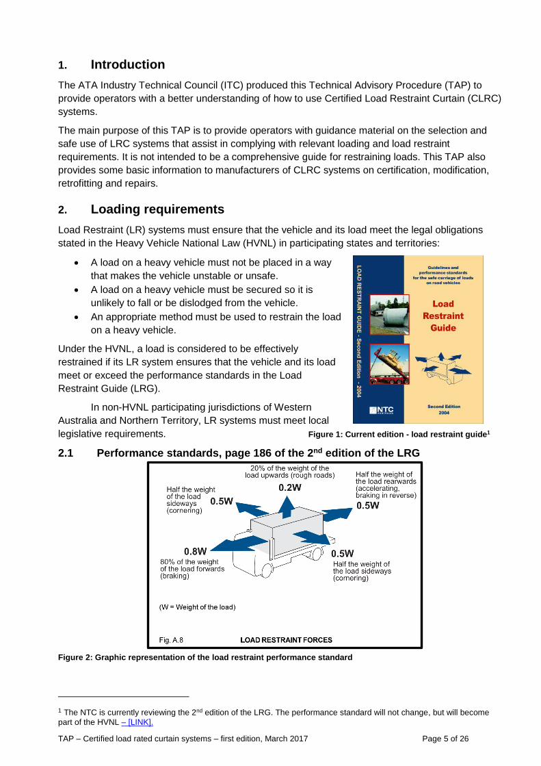
2.1 Performance standards, page 186 of the 2nd edition of the LRG
Figure 2: Graphic representation of the load restraint performance standard
1 The NTC is currently reviewing the 2nd edition of the LRG. The performance standard will not change, but will become
part of the HVNL – [LINK].
TAP – Certified load rated curtain systems – first edition, March 2017 Page 6 of 26
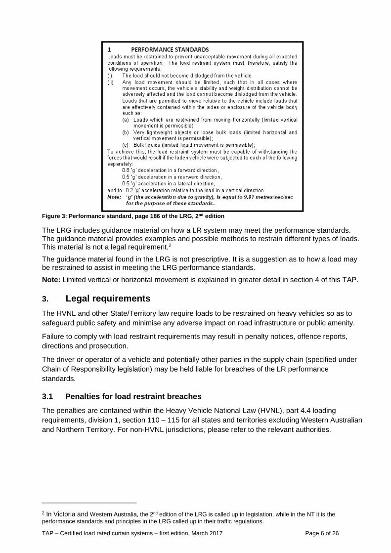
Figure 3: Performance standard, page 186 of the LRG, 2nd edition
The LRG includes guidance material on how a LR system may meet the performance standards. The guidance material provides examples and possible methods to restrain different types of loads. This material is not a legal requirement.2
The guidance material found in the LRG is not prescriptive. It is a suggestion as to how a load may be restrained to assist in meeting the LRG performance standards.
Note: Limited vertical or horizontal movement is explained in greater detail in section 4 of this TAP.
3. Legal requirements
The HVNL and other State/Territory law require loads to be restrained on heavy vehicles so as to
safeguard public safety and minimise any adverse impact on road infrastructure or public amenity.
Failure to comply with load restraint requirements may result in penalty notices, offence reports,
directions and prosecution.
The driver or operator of a vehicle and potentially other parties in the supply chain (specified under
Chain of Responsibility legislation) may be held liable for breaches of the LR performance
standards.
3.1 Penalties for load restraint breaches
The penalties are contained within the Heavy Vehicle National Law (HVNL), part 4.4 loading
requirements, division 1, section 110 – 115 for all states and territories excluding Western Australian
and Northern Territory. For non-HVNL jurisdictions, please refer to the relevant authorities.
2 In Victoria and Western Australia, the 2nd edition of the LRG is called up in legislation, while in the NT it is the
performance standards and principles in the LRG called up in their traffic regulations.
TAP – Certified load rated curtain systems – first edition, March 2017 Page 7 of 26
Penalties vary depending on the severity of the breach and can exceed $10,000 per breach.
Additional penalties and a general safety duty will come into force in the first part of 2018. Reckless
breaches of the general duty could attact penalties of up to $3 million for companies or $300,000 for
individuals or imprisonment for up to 5 years or both.
These penalties are indexed annually in accordance with the law.
3.2 Chain of Responsibility (CoR) and load restraint – [LINK to NHVR]
One of the goals of the HVNL is to protect public safety and road infrastructure from unsafe heavy
vehicles and unsecured loads. HVNL sections 110 and 111 describe the loading that apply to all
heavy vehicles (GVM and ATM above 4.5 tonne) in participating states (Qld, Vic, NSW, TAS, SA)
and territories (ACT).
These loading requirements are extended to parties in the transport supply chain by the HVNL
section 183 (extended liability). This provision encompasses the Chain of Responsibility.
Parties in the supply chain must take all reasonable steps to ensure that loads are safely and legally
restrained before they are transported on a road by a heavy vehicle. The person must:
prove that they did not know, and could not reasonably be expect to have known, of the
contravention concerned; and
that they took all reasonable steps to prevent the contravention; or
there were no steps they reasonably be expected to have taken to prevent the contravention.
[HVNL, s618].
In the event of a failure to meet the HVNL loading and load restraint requirements, any party in a
position to control or influence the loading and load restraint of the heavy vehicle may be held
responsible.
From 2018, business in the chain of responsibility will be subject to a general duty to ensure safety
so far as is reasonably practicable.
3.3 Who is a party in the transport supply chain?
For the purposes of the above, the NHVR3 has stated that the parties may include:
a) corporations, partnerships, unincorporated associations or other bodies corporate
b) employers and company directors
c) consignors/senders and consignees/receivers of the goods for transport
d) exporters and importers
e) primary producers
f) drivers (including a bus driver and an owner-driver)
g) prime contractors of drivers
h) operators of a transport company
i) schedulers of goods or passengers for transport, and the schedulers or allocators of drivers
j) loaders and unloaders of goods
k) loading managers (loading/unloading supervisors, or managers of the premises where this
occurs) and an employer of the vehicle’s driver, if the driver is an employed driver
3 NHVR Chain of Responsibility – [LINK].
TAP – Certified load rated curtain systems – first edition, March 2017 Page 8 of 26
4. General load restraint guidance
4.1 What is permissible movement?
The performance standards listed in the LRG state that loads can have some limited movement.
Loads that are permitted to move relative to the vehicle include loads effectively contained within the
sides or enclosure of the vehicle body such as:
Loads restrained from moving horizontally (limited vertical movement is permissible)
Very lightweight objects or loose bulk loads (limited horizontal and vertical movement is
permissible)
In cases where movement of the load occurs, the vehicle’s stability, handling, dimensions and
weight distribution must not be adversely affected and the load must not become dislodged from the
vehicle.
4.2 Limited vertical movement
A load is allowed limited upwards movement and shall be deemed adequately contained/restrained
in compliance with the LRG performance standards if:
The load is contained and no part of the load can become dislodged from the load
compartment of the vehicle.
The load is restrained or blocked in a way that prevents it from moving horizontally.
The load’s movement does not affect the vehicle handling/stability or mass (weight)
distribution.
Notes:
This does not necessarily mean the load has to be tied down but it must be restrained or
contained horizontally. This may be achieved by some form of blocking.
Some vertical movement of the load is permitted provided that the load is restrained
horizontally.
Loads should be unitised where possible with plastic stretch wrap, pallet strapping or similar
in order to minimise any potential movement.
It is recommended loads should, where possible, be transported in a vehicle that provides
containment. Such a vehicle may have a plate or label certifying that the vehicle’s structure
has been assessed as capable of providing part or all of the LR requirements to meet the
performance standards.
4.3 What is a direct restraint system (attachment, blocking and containment)?
A direct restraint system is a cost effective means of complying with the LRG performance
standards without necessarily tying down the load into place to prevent movement – forward, aft, left
or right.
In the case of full load (global) blocking (over the full width or full length of the load compartment),
void spaces should be filled with appropriate dunnage or air bags (for example, empty pallets
inserted vertically or horizontally and tightened by additional timber battens as necessary). Material
that may deform or shrink permanently such as solid foam of limited strength should not be used.
Small gaps between the unit loads and similar cargo items that cannot be avoided and are
necessary for the smooth packing and unpacking of the goods are acceptable and need not to be
filled.
TAP – Certified load rated curtain systems – first edition, March 2017 Page 9 of 26
As a guide, it is recommended that they do not individually exceed 50 mm. In the case of full load
(global) blocking, the sum of void spaces in any horizontal direction should not exceed 150 mm.4
However, between dense and rigid load items, such as steel, concrete or stone, void spaces should
be minimised, as much as possible.
The height of blocking components needs to suit the load and the integrity of its packaging. If the
load cannot be unitised with adequate packaging integrity, then the blocking at least needs to match
the height and width of the load. The strength of headboards and tailboards are critical to an overall
certified load restraint system when used for the purpose of blocking.
During delivery, loading and unloading the load, the remaining payload must maintain legal weight distribution and must not adversely affect the vehicle’s stability. More information is available at: [LINK] or https://www.gov.uk/government/publications/load-securing-vehicle-operator-guidance/load-securing-vehicle-operator-guidance
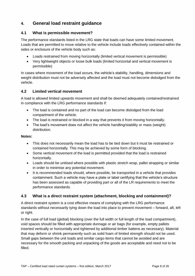
Figure 5: Blocked load from side
Figures 4: Block load from rear Figure 6: Partially blocked load
Figure 7: Partially blocked load Figure 8: Partially blocked load
Part or partial loads Even when they are contained by the body and curtain, part or partial loads are the most troublesome areas discussed at the roadside between truck drivers and the enforcement authorities. From section 4.1 of this TAP, in all cases where movement of the load occurs, the vehicle’s stability, handling, dimensions and weight distribution must not be adversely affected and the load must not become dislodged from the vehicle.
All partial loads must be adequately retrained. Further guidance for allowable gaps and voids is detailed earlier in this section.
4 Refer to European guidelines for load restraint 2014 – Section 5.4, full load (globe) blocking.
https://www.transportinfo.org/wp-content/uploads/2016/05/cargo_securing_guidelines_2014.pdf
TAP – Certified load rated curtain systems – first edition, March 2017 Page 10 of 26
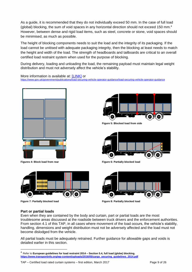
4.4 Pallet packaging and its integrity
The integrity of the LR system is critical. However, palletised cargo is often not recognised as being
a critical component of compliance and is not the responsibility of the CLRC system manufacturer or
necessarily the driver.
Pallet integrity should be tested to meet the LRG performance standards. The failure of pallet
wrapping can result in the failure of a LR system. See examples below of poor pallet integrity.
4.5 Load restraint equipment and acceptable levels of damage/wear
Where the supplier of LR equipment does not provide guidance for fair wear and tear of LR
equipment, the following may assist in assessing if the equipment is compliant:
a) The LRG provides guidance as to acceptable wear and tear limits in Part 2: Section H –
Load-Restraint Equipment.
b) The LRG recommends LR equipment must be replaced when weakened by 10 per cent or
more of their original minimum breaking strength. The LRG also lists other criteria for
assessing the serviceability of LR equipment and recommends replacement of LR equipment
if these criteria are present or are not met.
c) LR equipment that does not meet the serviceability criteria detailed in the LRG should not be
used for the purpose of restraining loads on a heavy vehicle.
Figure 10: Examples of testing pallet packaging integrity
Figure 9: Example of poor pallet load integrity.
TAP – Certified load rated curtain systems – first edition, March 2017 Page 11 of 26
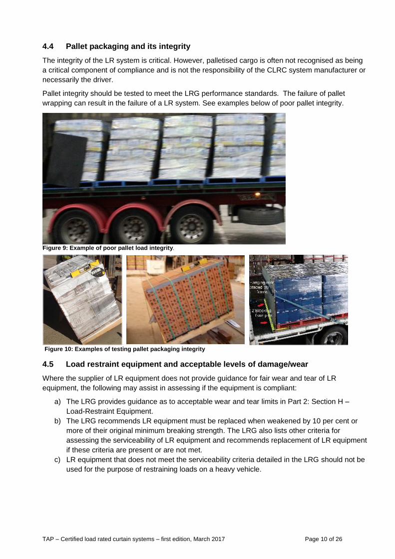
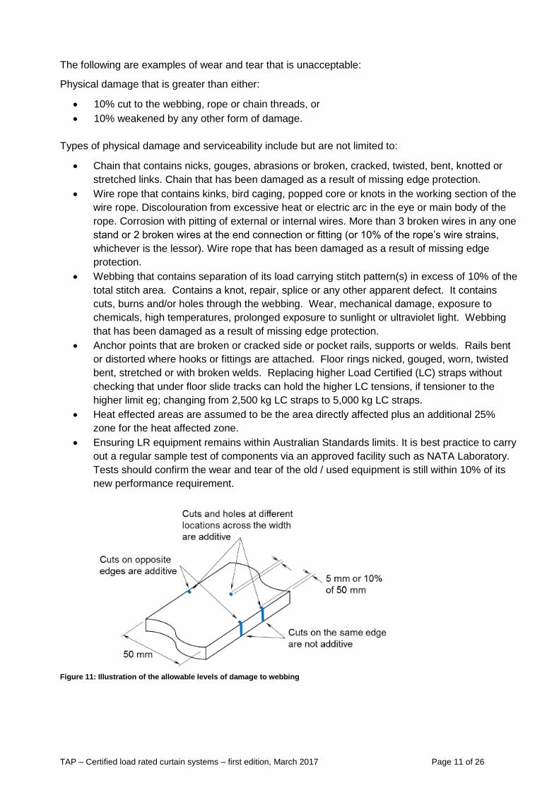
The following are examples of wear and tear that is unacceptable:
Physical damage that is greater than either:
10% cut to the webbing, rope or chain threads, or
10% weakened by any other form of damage.
Types of physical damage and serviceability include but are not limited to:
Chain that contains nicks, gouges, abrasions or broken, cracked, twisted, bent, knotted or
stretched links. Chain that has been damaged as a result of missing edge protection.
Wire rope that contains kinks, bird caging, popped core or knots in the working section of the
wire rope. Discolouration from excessive heat or electric arc in the eye or main body of the
rope. Corrosion with pitting of external or internal wires. More than 3 broken wires in any one
stand or 2 broken wires at the end connection or fitting (or 10% of the rope’s wire strains,
whichever is the lessor). Wire rope that has been damaged as a result of missing edge
protection.
Webbing that contains separation of its load carrying stitch pattern(s) in excess of 10% of the
total stitch area. Contains a knot, repair, splice or any other apparent defect. It contains
cuts, burns and/or holes through the webbing. Wear, mechanical damage, exposure to
chemicals, high temperatures, prolonged exposure to sunlight or ultraviolet light. Webbing
that has been damaged as a result of missing edge protection.
Anchor points that are broken or cracked side or pocket rails, supports or welds. Rails bent
or distorted where hooks or fittings are attached. Floor rings nicked, gouged, worn, twisted
bent, stretched or with broken welds. Replacing higher Load Certified (LC) straps without
checking that under floor slide tracks can hold the higher LC tensions, if tensioner to the
higher limit eg; changing from 2,500 kg LC straps to 5,000 kg LC straps.
Heat effected areas are assumed to be the area directly affected plus an additional 25%
zone for the heat affected zone.
Ensuring LR equipment remains within Australian Standards limits. It is best practice to carry
out a regular sample test of components via an approved facility such as NATA Laboratory.
Tests should confirm the wear and tear of the old / used equipment is still within 10% of its
new performance requirement.
Figure 11: Illustration of the allowable levels of damage to webbing
TAP – Certified load rated curtain systems – first edition, March 2017 Page 12 of 26
4.6 Use of fibre rope as part of the load restraint system
Only fibre ropes that comply with the Australian Standard AS/NZS 4345 Motor vehicles – Cargo
Restraint Systems - Transport Fibre Rope, or an equivalent international standard should be used.
Sisal and manila ropes do not comply with the above standard and should not be used for
restraining loads.
Additionally, the ATA recommends that synthetic rope should also not be used for the restraint of the
load and alternative methods of restraint be investigated as best practice. It may be used to restrain
light cubic loads and/or for restraining other load elements in position for that component to carry the
load, such as dunnage and gates. In most cases, it is difficult to define a ropes rating and it is
difficult to consistently achieve a known clamping force or lashing capacity (LC).
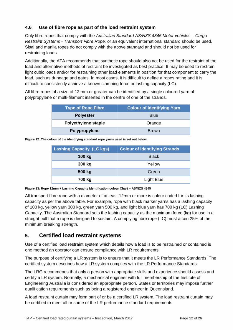
All fibre ropes of a size of 12 mm or greater can be identified by a single coloured yarn of
polypropylene or multi-filament inserted in the centre of one of the strands.
Figure 12: The colour of the identifying standard rope yarns used is set out below.
Figure 13: Rope 12mm + Lashing Capacity Identification colour Chart – AS/NZS 4345
All transport fibre rope with a diameter of at least 12mm or more is colour coded for its lashing
capacity as per the above table. For example, rope with black marker yarns has a lashing capacity
of 100 kg, yellow yarn 300 kg, green yarn 500 kg, and light blue yarn has 700 kg (LC) Lashing
Capacity. The Australian Standard sets the lashing capacity as the maximum force (kg) for use in a
straight pull that a rope is designed to sustain. A complying fibre rope (LC) must attain 25% of the
minimum breaking strength.
5. Certified load restraint systems
Use of a certified load restraint system which details how a load is to be restrained or contained is
one method an operator can ensure compliance with LR requirements.
The purpose of certifying a LR system is to ensure that it meets the LR Performance Standards. The
certified system describes how a LR system complies with the LR Performance Standards.
The LRG recommends that only a person with appropriate skills and experience should assess and
certify a LR system. Normally, a mechanical engineer with full membership of the Institute of
Engineering Australia is considered an appropriate person. States or territories may impose further
qualification requirements such as being a registered engineer in Queensland.
A load restraint curtain may form part of or be a certified LR system. The load restraint curtain may
be certified to meet all or some of the LR performance standard requirements.
Type of Rope Fibre Colour of Identifying Yarn
Polyester Blue
Polyethylene staple Orange
Polypropylene Brown
Lashing Capacity (LC kgs) Colour of Identifying Strands
100 kg Black
300 kg Yellow
500 kg Green
700 kg Light Blue
TAP – Certified load rated curtain systems – first edition, March 2017 Page 13 of 26
6. Certified Load Restraint Curtain (CLRC) systems
A CLRC system usually includes:-
The body of the trailer/truck
Webbing, buckles, hooks, rollers and webbing loop connections
Internal vehicle blocking structures (support posts and roof structure)
May include gates, doors, hinges and other types of LR equipment plus mezzanine floors
and supporting posts/panels/gates.
A LRC system must restrain a load so that it meets the LR performance standards.
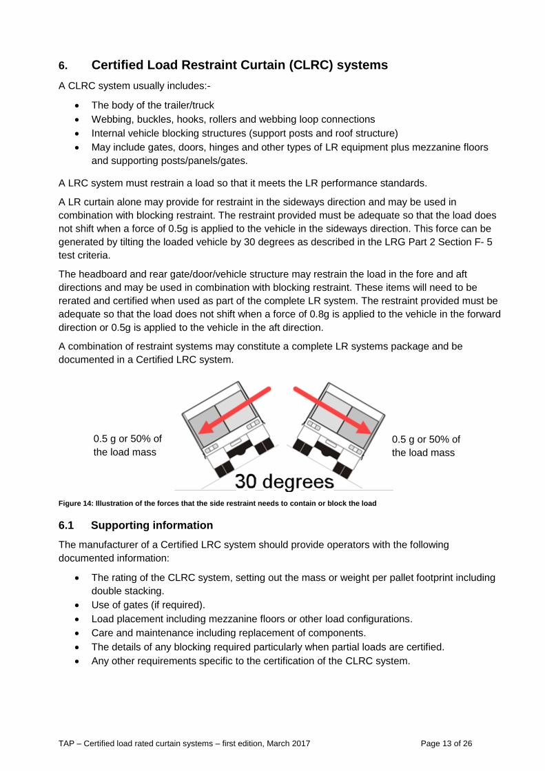
A LR curtain alone may provide for restraint in the sideways direction and may be used in
combination with blocking restraint. The restraint provided must be adequate so that the load does
not shift when a force of 0.5g is applied to the vehicle in the sideways direction. This force can be
generated by tilting the loaded vehicle by 30 degrees as described in the LRG Part 2 Section F- 5
test criteria.
The headboard and rear gate/door/vehicle structure may restrain the load in the fore and aft
directions and may be used in combination with blocking restraint. These items will need to be
rerated and certified when used as part of the complete LR system. The restraint provided must be
adequate so that the load does not shift when a force of 0.8g is applied to the vehicle in the forward
direction or 0.5g is applied to the vehicle in the aft direction.
A combination of restraint systems may constitute a complete LR systems package and be
documented in a Certified LRC system.
Figure 14: Illustration of the forces that the side restraint needs to contain or block the load
6.1 Supporting information
The manufacturer of a Certified LRC system should provide operators with the following
documented information:
The rating of the CLRC system, setting out the mass or weight per pallet footprint including
double stacking.
Use of gates (if required).
Load placement including mezzanine floors or other load configurations.
Care and maintenance including replacement of components.
The details of any blocking required particularly when partial loads are certified.
Any other requirements specific to the certification of the CLRC system.
0.5 g or 50% of
the load mass
0.5 g or 50% of
the load mass
TAP – Certified load rated curtain systems – first edition, March 2017 Page 14 of 26
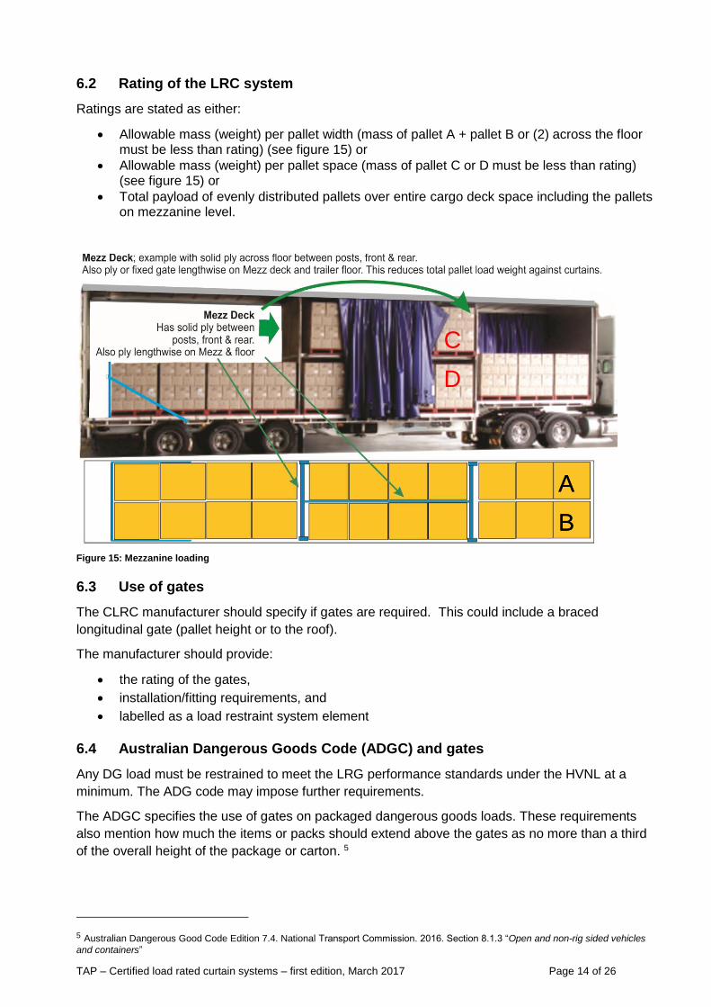
6.2 Rating of the LRC system
Ratings are stated as either:
Allowable mass (weight) per pallet width (mass of pallet A + pallet B or (2) across the floor must be less than rating) (see figure 15) or
Allowable mass (weight) per pallet space (mass of pallet C or D must be less than rating) (see figure 15) or
Total payload of evenly distributed pallets over entire cargo deck space including the pallets on mezzanine level.
Figure 15: Mezzanine loading
6.3 Use of gates
The CLRC manufacturer should specify if gates are required. This could include a braced
longitudinal gate (pallet height or to the roof).
The manufacturer should provide:
the rating of the gates,
installation/fitting requirements, and
labelled as a load restraint system element
6.4 Australian Dangerous Goods Code (ADGC) and gates
Any DG load must be restrained to meet the LRG performance standards under the HVNL at a
minimum. The ADG code may impose further requirements.
The ADGC specifies the use of gates on packaged dangerous goods loads. These requirements
also mention how much the items or packs should extend above the gates as no more than a third
of the overall height of the package or carton. 5
5 Australian Dangerous Good Code Edition 7.4. National Transport Commission. 2016. Section 8.1.3 “Open and non-rig sided vehicles
and containers”
A
B
A
B
C
D
TAP – Certified load rated curtain systems – first edition, March 2017 Page 15 of 26
These requirements were put in place before load restraint curtain systems became widely
available. The ADGC does not define a rating or performance requirement for the gate. All loads
must be safely restrained regardless and comply with the LR performance standards.
It should be noted that the gates referred to within the ADGC could be mounted/attached to either
the body or be part of the transport stillage.
6.5 Examples of load placement including mezzanine floors
Stacked loads
As an example, a CLRC system may define the maximum mass (weight) per pallet or 1,165 3 mm
square pallet footprint as 1,850 kg with post centres up to 2,800 mm apart. The load may be a
“stable single level load” or “stacked load” such as cartons on pallets. The load height of adjacent
pallets may be of similar height so as to be a block for each other. The load per pallet space usually
includes double stacked or second deck pallets.
Note:- with stacked pallets, the integrity of the double stacked pallet should be tested separately.
Figure 16: Stacked pallet configurations
Figure 16 illustrates a double stacked load. Figure 17 below illustrates two single stacked levels with
a mezzanine level (red) – total load per pallet space = 1,850kg, red posts shown at every second
pallet, about 2,400 mm apart.
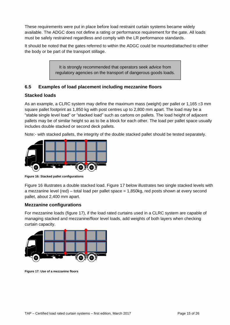
Mezzanine configurations
For mezzanine loads (figure 17), if the load rated curtains used in a CLRC system are capable of
managing stacked and mezzanine/floor level loads, add weights of both layers when checking
curtain capacity.
Figure 17: Use of a mezzanine floors
It is strongly recommended that operators seek advice from
regulatory agencies on the transport of dangerous goods loads.
TAP – Certified load rated curtain systems – first edition, March 2017 Page 16 of 26
6.6 Mixed or partial loads – refer to section 4.3 of this TAP
Manufacturers of LRC systems must specify if their equipment can handle mixed loads. The
information provided must also include how to restrain partial loads.
7. Certified Load Restraint Curtain (CLRC) system documentation
A CLRC system should be supplied with documentation that includes the following information.
7.1 Certificate of assessment
A certificate of assessment should include details of the LR equipment that make up the system,
how the LR equipment should be used and what loads can be restrained using the LRC system.
The certificate of assessment should detail the testing of the CLRC system and list who completed
the testing and their qualifications. This is typically held by the CLRC manufacturer and LR certifying
person/company. The level of detail in the CLRC system certificate can vary significantly, depending
on the complexity of the system itself.
7.2 CLRC system usage instructions
The CLRC system certificate should be carried in the vehicle or on the trailer/body, and should be
readily available for review. The certificate should provide clear instruction to the operator and any
other relevant party on how to use the CLRC system in the form of work instructions or standard
operating procedures, to ensure the CLRC system is correctly applied to a load to ensure
compliance with LR performance standards.
The level of detail in the certificate can vary significantly depending on the complexity of the
requirements. It is recommended that it should be pictorial with enough information to clearly define
the load that can be restrained and how it is contained.
It is strongly recommended to obtain certification from the LRC system manufacturer stating
explicitly under what conditions vertical and horizontal movement is allowed while still complying
with the LR performance standards.
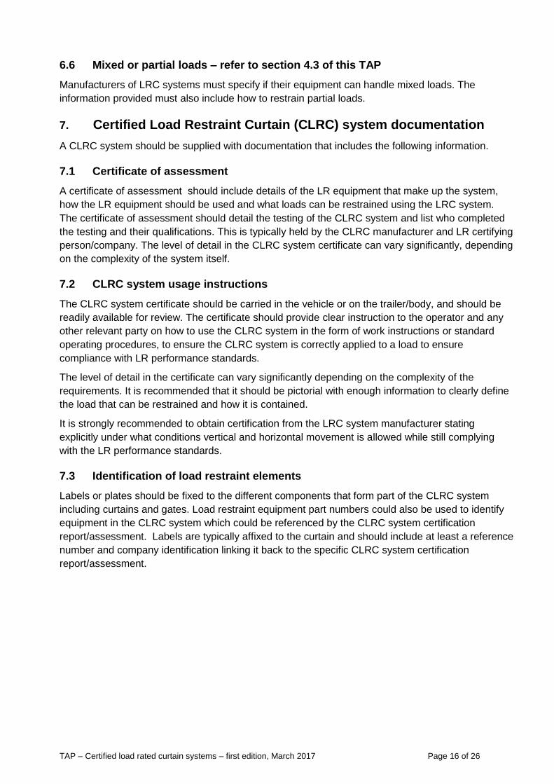
7.3 Identification of load restraint elements
Labels or plates should be fixed to the different components that form part of the CLRC system
including curtains and gates. Load restraint equipment part numbers could also be used to identify
equipment in the CLRC system which could be referenced by the CLRC system certification
report/assessment. Labels are typically affixed to the curtain and should include at least a reference
number and company identification linking it back to the specific CLRC system certification
report/assessment.
TAP – Certified load rated curtain systems – first edition, March 2017 Page 17 of 26
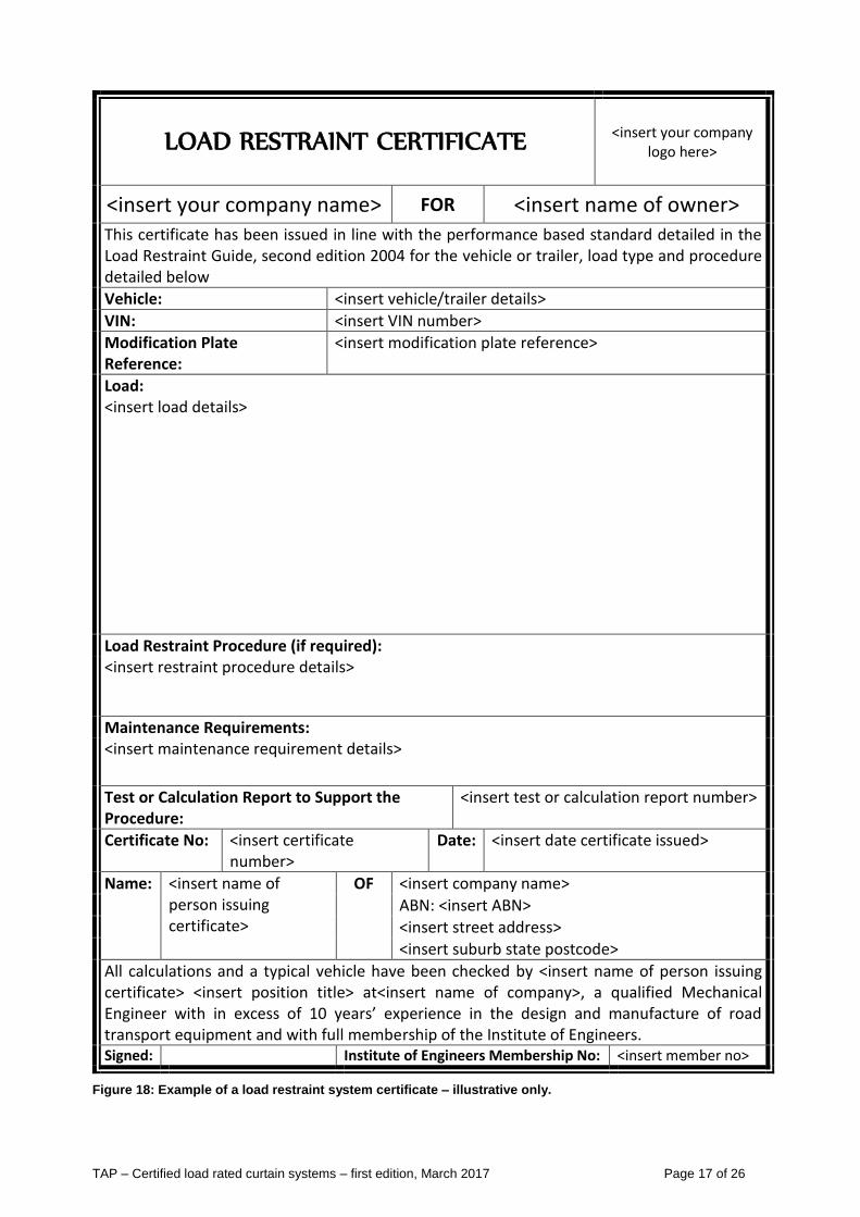
LOAD RESTRAINT CERTIFICATE <insert your company logo here>
<insert your company name> FOR <insert name of owner> This certificate has been issued in line with the performance based standard detailed in the Load Restraint Guide, second edition 2004 for the vehicle or trailer, load type and procedure detailed below
Vehicle: <insert vehicle/trailer details>
VIN: <insert VIN number>
Modification Plate Reference:
<insert modification plate reference>
Load: <insert load details>
Load Restraint Procedure (if required): <insert restraint procedure details>
Maintenance Requirements: <insert maintenance requirement details>
Test or Calculation Report to Support the Procedure:
<insert test or calculation report number>
Certificate No: <insert certificate number>
Date: <insert date certificate issued>
Name: <insert name of person issuing certificate>
OF <insert company name>
ABN: <insert ABN>
<insert street address>
<insert suburb state postcode>
All calculations and a typical vehicle have been checked by <insert name of person issuing certificate> <insert position title> at<insert name of company>, a qualified Mechanical Engineer with in excess of 10 years’ experience in the design and manufacture of road transport equipment and with full membership of the Institute of Engineers. Signed: Institute of Engineers Membership No: <insert member no>
Figure 18: Example of a load restraint system certificate – illustrative only.
TAP – Certified load rated curtain systems – first edition, March 2017 Page 18 of 26
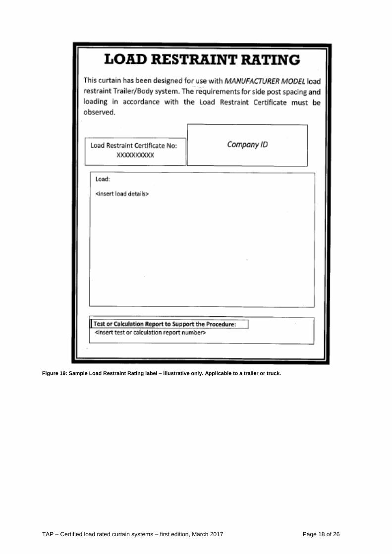
Figure 19: Sample Load Restraint Rating label – illustrative only. Applicable to a trailer or truck.
TAP – Certified load rated curtain systems – first edition, March 2017 Page 19 of 26
7.4 Load restraint rating plate
Vehicle Standards Bulletin number 6 (VSB#6) requires all heavy vehicle modifications to be
approved by an Authorised Vehicle Examiner (AVE) and a modification plate fitted, for modifications
such as the fitment of the body and the initial fitment of the fifth wheel.
All vehicle modifications must be performed by an appropriately accredited person and certified by a
person accredited to certify that type of modification.
Similarly, an appropriate person must certify load restraint systems including all body modifications
and certification of the system.
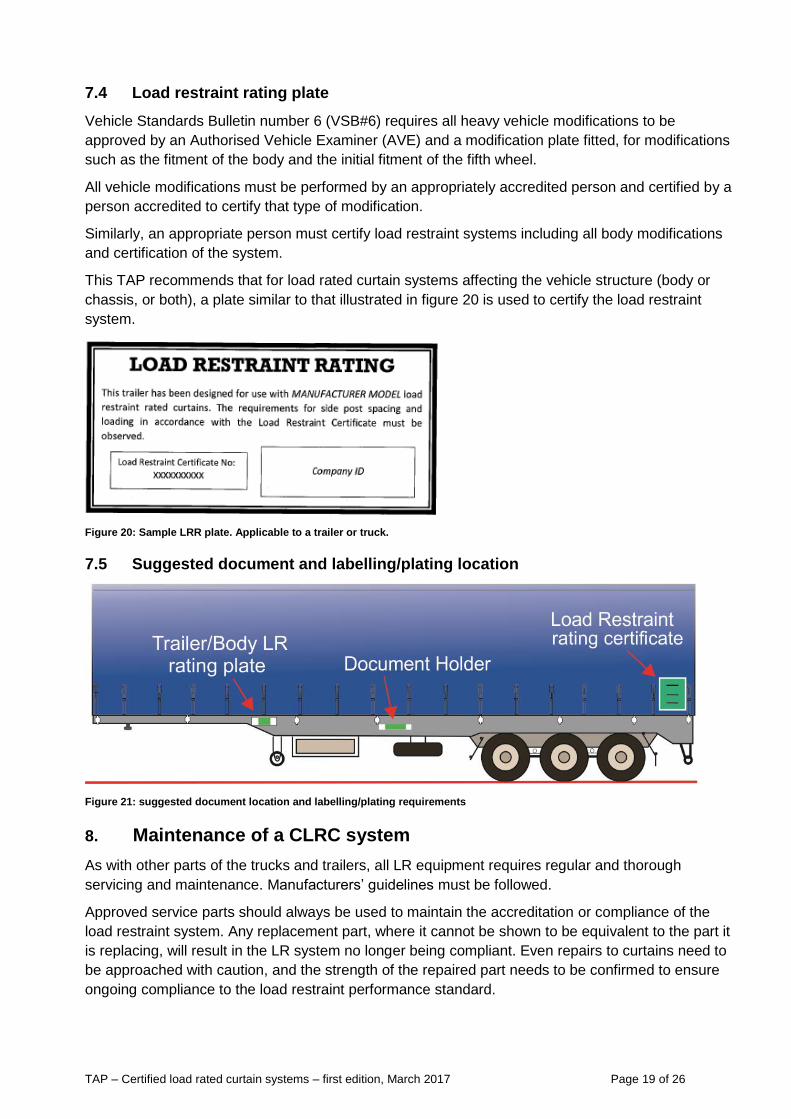
This TAP recommends that for load rated curtain systems affecting the vehicle structure (body or
chassis, or both), a plate similar to that illustrated in figure 20 is used to certify the load restraint
system.
Figure 20: Sample LRR plate. Applicable to a trailer or truck.
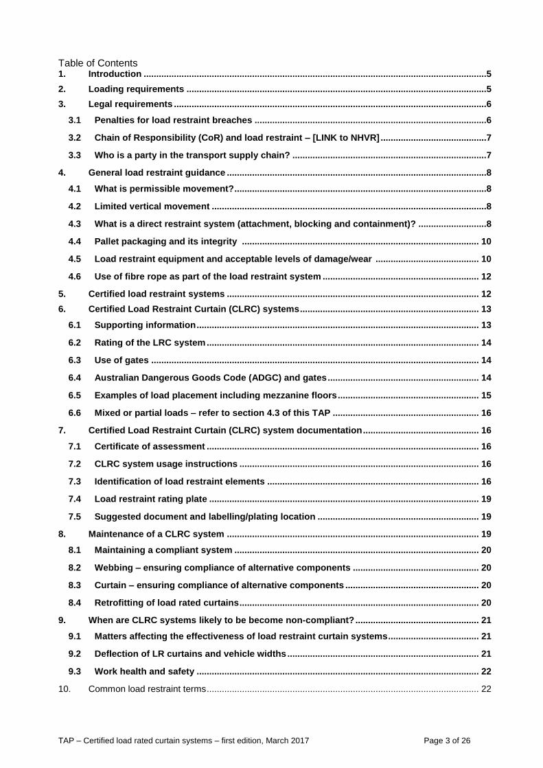
7.5 Suggested document and labelling/plating location
Figure 21: suggested document location and labelling/plating requirements
8. Maintenance of a CLRC system
As with other parts of the trucks and trailers, all LR equipment requires regular and thorough
servicing and maintenance. Manufacturers’ guidelines must be followed.
Approved service parts should always be used to maintain the accreditation or compliance of the
load restraint system. Any replacement part, where it cannot be shown to be equivalent to the part it
is replacing, will result in the LR system no longer being compliant. Even repairs to curtains need to
be approached with caution, and the strength of the repaired part needs to be confirmed to ensure
ongoing compliance to the load restraint performance standard.
TAP – Certified load rated curtain systems – first edition, March 2017 Page 20 of 26
8.1 Maintaining a compliant system
As with all certified LR systems, maintaining compliance with legal requirements is critical to
achieving ongoing safety. Typically, the original supplier of the CLRC system will be able to supply
replacement parts that will maintain the certification of the CLRC system. However if this not feasible
or practical any alternative replacement part must be able to maintain the compliance of the original
CLRC system. To achieve this it must be demonstrated that the new part is equivalent or superior to
the original component. The new part should have a unique identifier referenced in supplementary
documentation added to the CLRC system certification. A copy of the supplementary document
should be carried with the vehicle.
If inferior parts are used for repair or replacement of a CLRC system, the CLRC certification may no
longer be valid. Repairs to LR curtains also need to maintain the original strength and integrity of the
LR curtain to ensure ongoing certification of the CLRC system.
Ensure LR equipment remains within Australian Standards limits. It is best practice to carry out a
regular sample test of components via an approved facility such as NATA Laboratory. Tests should
confirm the wear and tear of the old / used equipment is still within 10% of its new performance
requirement.
8.2 Webbing – ensuring compliance of alternative components
The CLRC system certification report/assessment should provide additional information for the
webbing of its test load, all strap components, design strength and % or mm/m of stretch at the test
load. Any replacement strapping should match or exceed the strength requirements with matching
or lowering of the stretch capabilities to be considered equivalent. Unless a part has direct
equivalence (like for like) to the original, the load restraint system should be considered non
compliant and expert assistance should be sort.
8.3 Curtain – ensuring compliance of alternative components
The CLRC system certification report/assessment should provide additional information for the
curtain of its test load, design strength and % or mm/m of stretch at the test load in each direction.
Any replacement curtain material, including all components, needs to match the strength
requirements with a matching or lower stretch capabilities to be considered equivalent. Unless a part
has direct equivalence (like for like) to the original, the load restraint system should be considered
non compliant and expert assistance should be sought.
8.4 Retrofitting of load rated curtains
The fitment of load rated curtains to an existing vehicle cannot be considered part of a CLRC
system, unless the whole system has been assessed as complying with the LR performance
standards.
TAP – Certified load rated curtain systems – first edition, March 2017 Page 21 of 26
9. When are CLRC systems likely to be become non-compliant?
9.1 Matters affecting the effectiveness of load restraint curtain systems
Where there are heavy individual items with edges that may pierce the curtain.
If any element of the LR system is not in good functioning condition.
CLRC system does not cover all of the requirements of the LRG performance standards. The
overall system usually includes a rated headboard and tailboard to account for the forward and
aft requirements of the performance standards.
If gates are part of the LR system and are not mounted correctly, the load is not compliant.
In some cases additional lashings may be required to restrain heavy items of freight or to
make up for gaps in the load. Refer to the LR system certifier for further information.
The load being carried is specifically applicable to the certified LR system. The system for a
different load top will need to be certified.
When loaded pallets or packs have large gaps and spaces (refer to section 4 blocking) that will allow too much load-shift or movement during travel. Such loads should be fully assessed and tested as per the test methods listed in the LRG performance standard – see section F.
9.2 Deflection of LR curtains and vehicle widths
Heavy Vehicle National Law applies across Australia except in Western Australia and Northern
Territory. The Heavy Vehicle (Mass, Dimension and Loading) National Regulation under the HVNL,
defines the maximum width for a heavy vehicle as 2.5 metres.
The HVNL, when considering vehicle width, disregards the following:
(a) rear vision mirrors, signalling devices and side-mounted lamps and reflectors;
(b) anti-skid devices mounted on wheels, central tyre inflation systems, tyre pressure
gauges;
(c) permanently fixed webbing assembly-type devices, including, for example, curtain-side
devices, if the maximum distance across the body including any part of the devices does
not exceed 2.55m.
The Australian Design Rules (ADR) defines the requirement for new vehicles via ADR 43/01 that the
overall width must not exceed 2.5 m with the following definition as:
the maximum distance measured across the body including wheel guards, but excluding:
rear vision mirrors, signalling devices and side-mounted lamps and reflectors;
anti-skid devices mounted on wheels, central tyre inflation systems, tyre pressure gauges;
permanently fixed webbing-assembly-type devices – such as curtain-side devices, provided
that the maximum distance measured across the body including any part of the devices does
not exceed 2.55 m.
Where there is a conflict between the ADR and HVNL or HVNL does not cover the area, the ADR’s
will take precedence over HVNL.
Deflection of curtains
A deflection in the certified load restraint curtain system should not increase the vehicle’s width
beyond 2.5 m. If it does, roadside enforcement may treat this as an offence against:-
(a) Width requirements - the vehicle together with its load is over 2.5 metres
(b) Load requirements - the load restraint system failed to restrain the load within the limits of
the vehicle.
TAP – Certified load rated curtain systems – first edition, March 2017 Page 22 of 26
As a guide for vehicle stability, the deflection of the certified load restraint curtain system will limit the capacity for restraining many loads. In the absence of any test data or guidelines on allowable load shift for the different types of load, the maximum sideways deflection of the restraint system including side curtains should be limited to 100 mm.6 As a result, for a 2.5 m wide body with a CLRC system, the load is considered restrain up to an overall width of 2.6 m, but is over width. However, at a width greater than 2.6 m it will be considered both unrestrained and overall width.
9.3 Work health and safety
CLRC systems help reduce loading and unloading times, and improve safety by avoiding the need
for an operator to climb on to the heavy vehicle’s load deck. Always use caution when opening and
closing curtains, even if they are not part of the load restraint system. If the curtain is bulging, the
load has moved and the curtain should be opened with care after the stability of the load has been
assessed.
10. Common load restraint terms
Air bag An inflatable barrier placed between sections of the load and/or the
vehicle to stop any movement of load. It can be disposable or reusable.
Anchor point Fitting or attachment on a vehicle’s bodies or load to anchor lashings.
ATM Of a heavy trailer, means the total maximum mass of the trailer, as stated (Aggregate Trailer Mass) by the manufacturer together with its load and the mass imposed on the towing vehicle by the trailer when the towing vehicle and trailer are on a horizontal surface. See also GTM.
Bolster Rigid support base (or with a stanchion) commonly used to support Iogs
on jinkers.
Blocking Blocking is a load restraint method. Material used for blocking varies
widely, from timber to air bag and placed between the load and the
vehicle structure to prevent movement of the load (also see dunnage).
Centre of gravity The centre of balance of a load or mass.
Cheater bar Usually a length of pipe placed over the operating lever of a dog so as to
extend its length. (The use of these extensions is not approved by any
manufacturer and can be dangerous).
Chocks Usually wedge shaped blocks used to prevent movement of the load (also
see wedges).
Claw hook A chain hook in the shape of a claw.
Coaming A frame border around the outside of a vehicle's loading deck.
Contained load Is a load prevented from dislodging from the vehicle by the vehicle
structure, gates, sides, racks, headboards, stanchions etc or other parts of
the load. Certified LR curtains are not listed in the LRG, but should be
allowed as part of an overall certified LR system.
Containment restraints Side curtains and gates may be used as containment restraints.
Corner protectors Material used to protect lashings and the exposed edges of loads and
vehicles, and to allow lashings to slide freely when being tensioned.
Cradle A frame shaped to support a load.
6 Source LRG 2004 Section I, paragraph 2.2 – Direct Restraint Systems
TAP – Certified load rated curtain systems – first edition, March 2017 Page 23 of 26
Deck The load carrying surface of a vehicle.
Dog A chain tensioner incorporating an over-centre locking action with a fixed
or pivoting lever.
Dunnage Packing placed either between items of a load or between the base of a
load and the surface of the vehicle’s loading deck (also see blocking). The
word 'dunnage’ is derived from the era of sailing ships where wood
packing was used to raise the cargo above the bilge water in the hold.)
Flush deck A flat loading deck without a raised coaming rail.
Gates Permanent or removable vertical frames used at the front, sides and rear
of a vehicles loading deck to contain its load. The front gate is usually
called a loading rack or load rack.
GCM The value specified by the manufacturer of a vehicle as being the sum of (Gross Combination Mass) its gross vehicle mass plus the maximum loaded mass of any trailer or motor vehicle that it can tow in combination or limited by the road authorities.
GTM (gross trailer mass) The maximum mass transmitted to the ground by the axles of the trailer when it is loaded to its GVM and connected to a towing vehicle.
GVM The maximum mass of a motor vehicle when loaded, as specified by its
(Gross Vehicle Mass) manufacturer or limited by the road authorities.
Headboard Usually a permanent vertical frame used at the front of a vehicle's loading deck to contain its load (also known as a bulkhead).
Heavy vehicle For the purposes of this document, a heavy vehicle is a load carrying
goods vehicle weighing more than 4.5 tonnes.
Lashings Fastening devices, chains, cables, ropes or webbing used to restrain
loads.
Lashing capacity (LC) The maximum force (in kilograms) that a lashing system is designed to
use.
Load binding A device used for tensioning a lashing (see dog or tensioner).
Load capacity The difference between the GVM or GTM/ATM of a load carrying vehicle
and its tare mass.
Load mat A sheet of material used to increase friction and protect the load (also
called anti-slip mat or friction mat).
Load restraints Load restraints are classified as tie-down/friction restraints or direct
restraints (containing, blocking and attaching) or a combination of the two.
Commonly, webbing and chains are used for tie-downs and direct
restraints.
Pallet A portable wooden or plastic platform or tray onto which loads are placed
for mechanical handling. Sizes vary around the world. The Australian
pallet is 1,165 3 mm square. Refer to AS4068.
Pawl A lever or lock which prevents reverse rotation on a winch.
Pockets Housings or slots fixed to the vehicle to locate gates, stakes or loading
pegs.
Shackle A metal coupling link closed by a bolt, which can be used for attaching
chain fittings.
Shoring bar/pogo stick Adjustable metal beam used to restrain or segregate sections of load
(also known as a staling pole).
TAP – Certified load rated curtain systems – first edition, March 2017 Page 24 of 26
Stanchion A large upright support fixed to the side of a vehicle or bolster for
sideways restraint, eg; logs, pipe, poles, steel.
Stillage A metal structure for containing individual items of load.
Tare mass The unladen mass of a motor vehicle or trailer, ready for service and if
applicable less driver with only 10 litres.
Tensioner A device used to tighten a lashing (winch, dog, hand ratchet etc).
Tie down method A tie down method is when the load is prevented from moving by friction
only.
Tie rail A round rail which skirts the perimeter of the loading deck below the
coaming rail.
Turnbuckle A tensioner consisting of a threaded sleeve and two mating threaded
ends.
Twist lock A locking device with a rotating head or pin, which normally engages a
comer casting on the load. Eg; containers.
Wedge A piece of rigid material, thick at one end and tapering to a thinner edge at
the other (also see chocks).
tpiinrStaiWG
M©
Wist teeft
wedge
wbicft
tpiinrStaiWG
M©
Wist teeft
TAP – Certified load rated curtain systems – first edition, March 2017 Page 25 of 26
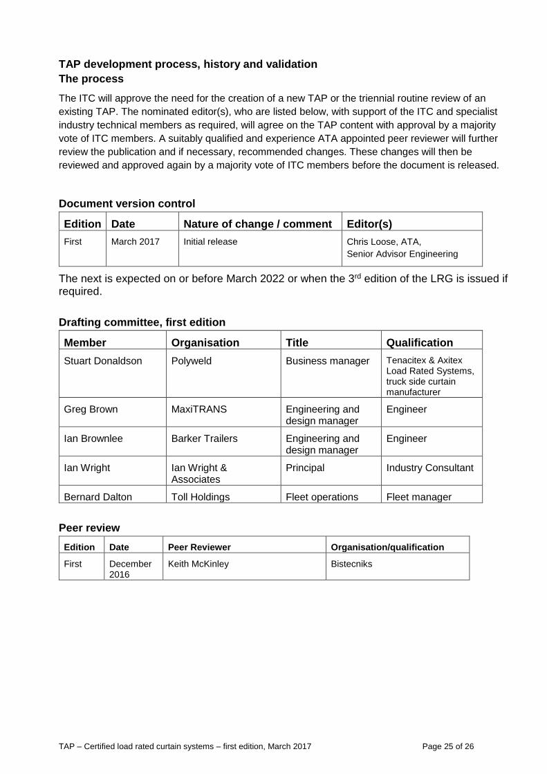
TAP development process, history and validation
The process
The ITC will approve the need for the creation of a new TAP or the triennial routine review of an
existing TAP. The nominated editor(s), who are listed below, with support of the ITC and specialist
industry technical members as required, will agree on the TAP content with approval by a majority
vote of ITC members. A suitably qualified and experience ATA appointed peer reviewer will further
review the publication and if necessary, recommended changes. These changes will then be
reviewed and approved again by a majority vote of ITC members before the document is released.
Document version control
Edition Date Nature of change / comment Editor(s)
First March 2017 Initial release Chris Loose, ATA,
Senior Advisor Engineering
The next is expected on or before March 2022 or when the 3rd edition of the LRG is issued if required.
Drafting committee, first edition
Member Organisation Title Qualification
Stuart Donaldson Polyweld Business manager Tenacitex & Axitex Load Rated Systems, truck side curtain manufacturer
Greg Brown MaxiTRANS Engineering and design manager
Engineer
Ian Brownlee Barker Trailers Engineering and design manager
Engineer
Ian Wright Ian Wright & Associates
Principal Industry Consultant
Bernard Dalton Toll Holdings Fleet operations Fleet manager
Peer review
Edition Date Peer Reviewer Organisation/qualification
First December 2016
Keith McKinley Bistecniks
TAP – Certified load rated curtain systems – first edition, March 2017 Page 26 of 26
About the ATA Industry Technical Council:
The Industry Technical Council (ITC) is a standing committee of the Australian Trucking Association
(ATA). The ITC’s mission is to improve trucking equipment, its maintenance and maintenance
management. The ITC was established in 1995.
As a group, the ITC provides the ATA with robust professional advice on technical matters to help
underpin the ATA’s evidence based policymaking. It is concerned with lifting technical and
maintenance standards, improving the operational safety of the heavy vehicle sector, and the
development of guidelines and standards for technical matters.
ITC performs a unique service in the Australian trucking industry by bringing operators, suppliers,
engineers and other specialists together in a long-term discussion forum. Its members provide
expert and independent advice in the field to inform the work of the ITC. The outcomes from ITC
benefit all ITC stakeholders and the heavy vehicle industry at large.
The ITC operates under the Australian Trucking Association’s Council, which formulates industry
policy for implementation by the organisation.
Joining ITC:
We welcome applications to join the ITC. For further information,
please call the ATA (02) 6253 6900
email [email protected]
or download information from www.truck.net.au and follow the links under the members tab.