Draft AC 150/5200-30D, Airport Winter Safety and...
90
U.S. Department of Transportation Federal Aviation Administration Advisory Circular Subject: Airport Field Condition Assessments and Winter Operations Safety Date: Draft Initiated By: AAS-300 AC No: 150/5200-30D 1 PURPOSE. 1 This advisory circular (AC) provides guidance to assist airport operators in assessing 2 and reporting field conditions through the utilization of the Runway Condition 3 Assessment Matrix (RCAM), conducting and reporting runway friction surveys, and 4 developing snow removal and control procedures. 5 2 CANCELLATION. 6 This AC cancels AC 150/5200-30C, Airport Winter Safety and Operations, dated 7 December 9, 2008 8 3 APPLICATION. 9 The information contained in this AC is guidance for the airport operators for 10 developing plans, methods, and procedures for identifying, reporting, and removal of 11 airport contaminants. The use of this AC is the preferred method of compliance, 12 acceptable by the Administrator, for airports certificated under Title 14 Code of Federal 13 Regulations Part 139, Certification of Airports, Section 139.313, Snow and Ice Control, 14 and Section 139.339, Airport Condition Reporting. The use of this AC is also a method 15 of compliance for federally obligated airports. Further, the use of this AC is mandatory 16 for all projects funded with federal grant monies through the Airport Improvement 17 Program (AIP) and/or with revenue from the Passenger Facility Charge (PFC) Program. 18 (See Grant Assurance No. 34, Policies, Standards, and Specifications, and PFC 19 Assurance No. 9, Standards and Specifications.) For implementation purposes, all 20 certificated airports must submit revised Snow and Ice Control Plans to the FAA no 21 later than August 1, 2016 for approval. In addition, all certificated and federally 22 obligated airports are required to follow the Runway Condition Code requirements 23 effective October 1, 2016. At that time, certificated airports will be required to comply 24 with the remaining portions of this AC. 25 26
Transcript of Draft AC 150/5200-30D, Airport Winter Safety and...

U.S. Department
of Transportation
Federal Aviation
Administration
Advisory Circular
Subject: Airport Field Condition Assessments
and Winter Operations Safety
Date: Draft
Initiated By: AAS-300
AC No: 150/5200-30D
1 PURPOSE. 1
This advisory circular (AC) provides guidance to assist airport operators in assessing 2
and reporting field conditions through the utilization of the Runway Condition 3
Assessment Matrix (RCAM), conducting and reporting runway friction surveys, and 4
developing snow removal and control procedures. 5
2 CANCELLATION. 6
This AC cancels AC 150/5200-30C, Airport Winter Safety and Operations, dated 7
December 9, 2008 8
3 APPLICATION. 9
The information contained in this AC is guidance for the airport operators for 10
developing plans, methods, and procedures for identifying, reporting, and removal of 11
airport contaminants. The use of this AC is the preferred method of compliance, 12
acceptable by the Administrator, for airports certificated under Title 14 Code of Federal 13
Regulations Part 139, Certification of Airports, Section 139.313, Snow and Ice Control, 14
and Section 139.339, Airport Condition Reporting. The use of this AC is also a method 15
of compliance for federally obligated airports. Further, the use of this AC is mandatory 16
for all projects funded with federal grant monies through the Airport Improvement 17
Program (AIP) and/or with revenue from the Passenger Facility Charge (PFC) Program. 18
(See Grant Assurance No. 34, Policies, Standards, and Specifications, and PFC 19
Assurance No. 9, Standards and Specifications.) For implementation purposes, all 20
certificated airports must submit revised Snow and Ice Control Plans to the FAA no 21
later than August 1, 2016 for approval. In addition, all certificated and federally 22
obligated airports are required to follow the Runway Condition Code requirements 23
effective October 1, 2016. At that time, certificated airports will be required to comply 24
with the remaining portions of this AC. 25
26
mm/dd/yy D R A F T AC 150/5200-30D
ii
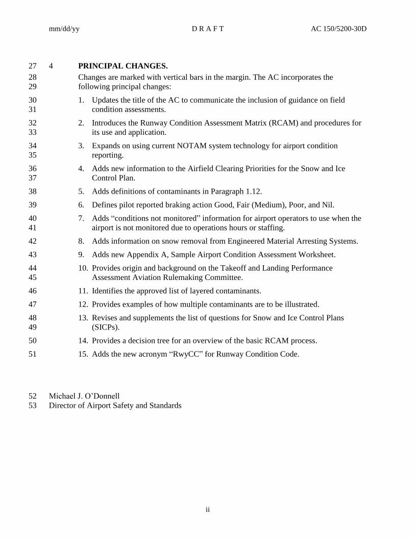
4 PRINCIPAL CHANGES. 27
Changes are marked with vertical bars in the margin. The AC incorporates the 28
following principal changes: 29
Updates the title of the AC to communicate the inclusion of guidance on field 1.30
condition assessments. 31
Introduces the Runway Condition Assessment Matrix (RCAM) and procedures for 2.32
its use and application. 33
Expands on using current NOTAM system technology for airport condition 3.34
reporting. 35
Adds new information to the Airfield Clearing Priorities for the Snow and Ice 4.36
Control Plan. 37
Adds definitions of contaminants in Paragraph 1.12. 5.38
Defines pilot reported braking action Good, Fair (Medium), Poor, and Nil. 6.39
Adds “conditions not monitored” information for airport operators to use when the 7.40
airport is not monitored due to operations hours or staffing. 41
Adds information on snow removal from Engineered Material Arresting Systems. 8.42
Adds new Appendix A, Sample Airport Condition Assessment Worksheet. 9.43
Provides origin and background on the Takeoff and Landing Performance 10.44
Assessment Aviation Rulemaking Committee. 45
Identifies the approved list of layered contaminants. 11.46
Provides examples of how multiple contaminants are to be illustrated. 12.47
Revises and supplements the list of questions for Snow and Ice Control Plans 13.48
(SICPs). 49
Provides a decision tree for an overview of the basic RCAM process. 14.50
Adds the new acronym “RwyCC” for Runway Condition Code. 15.51
Michael J. O’Donnell 52
Director of Airport Safety and Standards 53

mm/dd/yy D R A F T AC 150/5200-30D
CONTENTS
Paragraph Page
iii
CHAPTER 1. INTRODUCTION ................................................................................... 1-1 54
Overview. ................................................................................................................ 1-1 1.155
Background. ........................................................................................................... 1-1 1.256
Snow and Ice Control Committee. ........................................................................ 1-2 1.357
Airport Snow and Ice Control Committee (SICC). ............................................. 1-2 1.458
Snow Control Center (SCC). ................................................................................. 1-3 1.559
Airfield Clearing Priorities for the Snow and Ice Control Plan (SICP). ............ 1-3 1.660
Terminal and Landside – Ground Side Priority. ................................................. 1-4 1.761
Airfield Target Clearance Times........................................................................... 1-4 1.862
Sizing and Staffing Snow and Ice Control Equipment Fleet. .............................. 1-6 1.963
Storage of Snow and Ice Control Equipment. ...................................................... 1-6 1.1064
FAA-Approved Runway Friction Measuring Equipment. .................................. 1-6 1.1165
Definitions. .............................................................................................................. 1-7 1.1266
CHAPTER 2. THE SNOW AND ICE CONTROL PLAN ............................................... 2-1 67
Safety Requirements. ............................................................................................. 2-1 2.168
Airport Operators. ................................................................................................. 2-1 2.269
Snow and Ice Control Plans. ................................................................................. 2-1 2.370
Topics for Pre- and Post-Season SICC Meetings. ................................................ 2-2 2.471
Outlining a Snow and Ice Control Plan (SICP). .................................................. 2-4 2.572
Topics for Writing Instructions and Procedures for Winter Operations and 2.673
Notification. ............................................................................................................ 2-5 74
Runway Incursion Mitigation and Operations During Non-Towered Air 2.775
Traffic Control Periods. ......................................................................................... 2-5 76
Staff Training and Recordkeeping. ....................................................................... 2-6 2.877
Other Related Items. .............................................................................................. 2-7 2.978
CHAPTER 3. FORECAST TECHNOLOGY FOR AIRPORT OPERATORS ................ 3-1 79
Weather Forecasting. ............................................................................................. 3-1 3.180
FAA Forecasting Research and Development for Airport Operators. ............... 3-1 3.281
Forecasting Runway Surface Conditions. ............................................................ 3-2 3.382
CHAPTER 4. SNOW CLEARING OPERATIONS AND ICE PREVENTION ................ 4-1 83
Introduction. ........................................................................................................... 4-1 4.184

mm/dd/yy D R A F T AC 150/5200-30D
CONTENTS (CONTINUED)
Paragraph Page
iv
Snow Clearing Principles. ...................................................................................... 4-1 4.285
Controlling Snow Drifts. ...................................................................................... 4-10 4.386
Snow Disposal. ...................................................................................................... 4-11 4.487
Methods for Ice Control and Removal. .............................................................. 4-12 4.588
Approved Chemicals. ........................................................................................... 4-12 4.689
Runway Friction Improvements. ........................................................................ 4-15 4.790
Sand. ...................................................................................................................... 4-16 4.891
CHAPTER 5. SURFACE ASSESSMENT AND REPORTING ..................................... 5-1 92
Airport Operator Responsibility. .......................................................................... 5-1 5.193
Runway Friction Surveys. ..................................................................................... 5-2 5.294
Runway Condition Assessments. ........................................................................... 5-5 5.395
Applying the RCAM to a Runway Assessment. ................................................. 5-14 5.496
Upgrade Criteria Based on Friction Assessments. ............................................. 5-16 5.597
Reportable Contaminants without Performance Data. ..................................... 5-17 5.698
Condition Reporting. ........................................................................................... 5-17 5.799
Information Exchanged Between the Airport and Pilots. ................................. 5-18 5.8100
Requirements for Runway, Taxiway, and Apron and Holding Bay 5.9101
Closures. ............................................................................................................... 5-19 102
Letter of Agreement (LOA) Between Airport Operator and Air Traffic 5.10103
Control Tower. ..................................................................................................... 5-20 104
Continuous Monitoring. ....................................................................................... 5-20 5.11105
Airport Records and Log Controls. .................................................................... 5-21 5.12106
Using “Conditions Not Monitored” NOTAMs. .................................................. 5-21 5.13107
Winter NOTAM Abbreviations. ......................................................................... 5-21 5.14108
APPENDIX A. SAMPLE AIRPORT CONDITIONS ASSESSMENT WORKSHEET ... A-1 109
APPENDIX B. DEVELOPMENT OF RECOMMENDED SNOW BANK HEIGHT 110
PROFILES ............................................................................................................. B-1 111
APPENDIX C. SNOW AND ICE CONTROL AS A MATERIALS-HANDLING 112
PROBLEM ............................................................................................................. C-1 113
APPENDIX D. FAA-APPROVED DECELEROMETERS ............................................ D-1 114
APPENDIX E. PERFORMANCE SPECIFICATION FOR DECELEROMETERS ......... E-1 115
116 117

mm/dd/yy D R A F T AC 150/5200-30D
CONTENTS
Paragraph Page
v
FIGURES 118
Figure 1-1. Example of Prioritized Paved Areas for the Snow and Ice Control Plan.................. 1-4 119
Figure 3-1. Single Alter Wind Shield Type ................................................................................. 3-2 120
Figure 3-2. Schematic of Unidirectional Storm WSDDM Configuration ................................... 3-1 121
Figure 4-1. Snow Bank Profile Limits Along Edges of Runways and Taxiways with the 122
Airplane Wheels on Full Strength Pavement (see Figure 4-2 guidance) ............................... 4-6 123
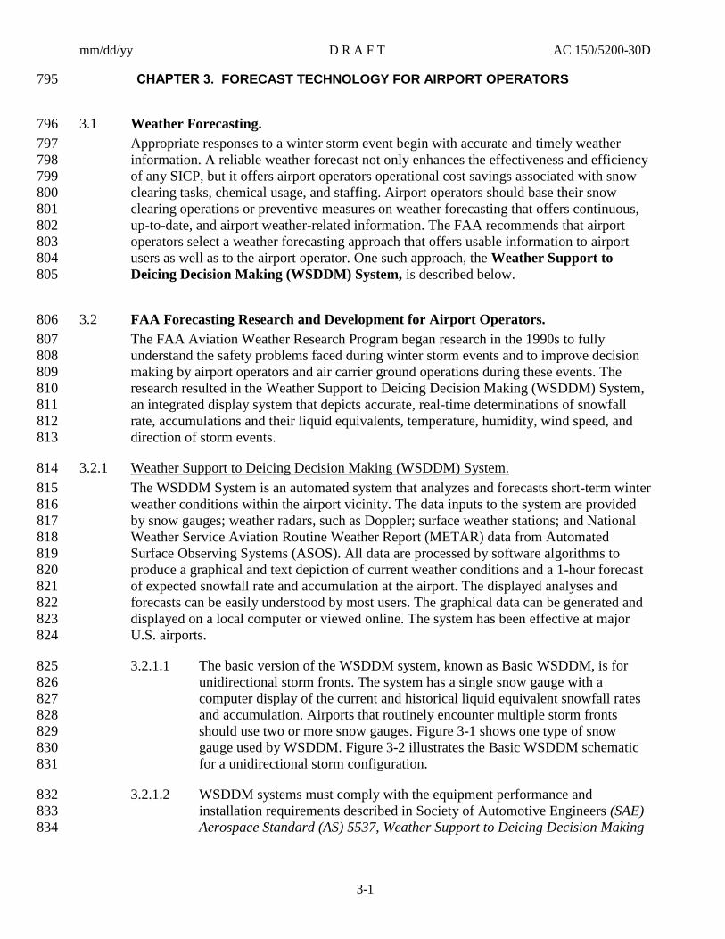
Figure 4-2. ILS CAT I and CAT II/III Snow Clearance Area Depth Limitations ....................... 4-7 124
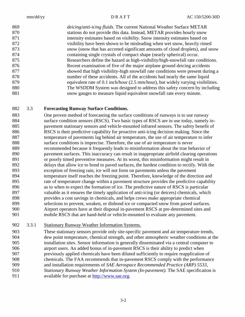
Figure 4-3. Possible Team Configuration with Perpendicular Wind ........................................... 4-8 125
Figure 4-4. Possible Team Configuration During Light Snowfall with Parallel or Calm 126
Wind ....................................................................................................................................... 4-8 127
Figure 4-5. Possible Team Configuration During Medium to Heavy Snowfall with Parallel or 128
Calm Wind (Dependent upon Rotary Plow performance) ..................................................... 4-9 129
Figure 4-6. Typical Snow Trench Dimensions .......................................................................... 4-11 130
Figure 5-1. Runway Condition Description Column of the RCAM ............................................ 5-9 131
Figure 5-2. Runway Condition Code (RwyCC) Column of the RCAM.................................... 5-10 132
Figure 5-3. Friction Assessment Column of the RCAM ........................................................... 5-12 133
Figure 5-4. Vehicle Deceleration or Directional Control Observation Column of the RCAM . 5-13 134
Figure 5-5. Pilot Reported Breaking Action Column of the RCAM ......................................... 5-14 135
Figure B-1. Individual Height Profiles of Airplane Wingtips and Outer and Inner Engine 136
Nacelles’ Lower Edges for Airplane Design Groups III and IV .................................................B-2 137
Figure B-2. Individual Height Profiles of Airplane Wingtips and Outer and Inner Engine 138
Nacelles’ Lower Edges for Airplane Design Groups V and VI (* indicates preliminary data) ..B-3 139
TABLES 140
Table 1-1. Clearance Times for Commercial Service Airports ................................................... 1-5 141
Table 1-2. Clearance Times for Non-Commercial Service Airports ........................................... 1-5 142
Table 4-1. Guidance for Airside Urea Application Rates .......................................................... 4-14 143
Table 4-2. Standard Gradation for Sand .................................................................................... 4-17 144
Table 4-3. Expanded Sand Gradation Standard ......................................................................... 4-18 145
Table 5-1. Friction Survey Example ............................................................................................ 5-5 146
Table 5-2. Runway Condition Assessment Matrix (RCAM)....................................................... 5-6 147

mm/dd/yy D R A F T AC 150/5200-30D
vi
This page intentionally left blank.148

mm/dd/yy D R A F T AC 150/5200-30D
1-1
CHAPTER 1. INTRODUCTION 149
Overview. 1.1150
The presence of contaminants such as snow, ice, or slush on airfield pavements causes 151
hazardous conditions that may contribute to airplane incidents and accidents. Further, 152
winter storm conditions usually reduce airport traffic volumes through flight delays and/or 153
cancellations and, in severe storm conditions, airport closures. The extent to which these 154
undesirable effects are minimized will depend on the approach taken by the airport 155
operator to closely monitoring and assess conditions and have mitigating practices at the 156
ready to combat potential and any existing contaminant conditions on the airport. This 157
revised AC introduces new concepts and practices and a different approach for airport 158
operator to use, which is a less subjective way of assessing airport conditions. The new 159
information being introduced in this AC goes a long way in harmonizing activities across 160
Lines of Business in relationship to addressing airport surface contaminants. An important 161
change associated with this harmonization is that aircraft manufactures have determined 162
that variances in contaminant type, depth and air temperature causes specific changes in 163
aircraft braking performance. As a result, it is possible to take the aircraft manufacturer’s 164
data for specific contaminants and produce the Runway Condition Assessment Matrix for 165
use by airport operators. This harmonization effort associated with identified 166
contaminants extends beyond our domestic airports to a point where our ICAO partners are 167
implementing similar standards and procedures to make the process of identifying airport 168
contaminants less subjective. In complying with Part 139 for certificated airports, the 169
NOTAM system will become more important for distributing airport conditions reports. 170
The use of other systems in accordance with Part 139.339(b) will be further defined for 171
clarity to ensure airport operators are making and acknowledging receipt notification to air 172
carrier and other airport agencies and tenants. 173
Background. 1.2174
Following the overrun accident of a Boeing 737 at Midway in December of 2005, the FAA 1.2.1175
found that the current state of the industry practices did not have adequate guidance and 176
regulation addressing operation on non-dry, non-wet runways, i.e., contaminated runways. 177
As such they chartered an Aviation Rulemaking Committee (ARC) to address Takeoff and 178
Landing Performance Assessment (TALPA) requirements for the appropriate Part 23, 25, 179
91K, 121, 125, 135, and 139 Parts of 14 CFR. In formulating their recommendations it 180
became clear to the ARC that the ability to communicate actual runway conditions to the 181
pilots in real time and in terms that directly relate to expected aircraft performance was 182
critical to the success of the project. While researching current NOTAM processes 183
numerous significant short comings were discovered that hampered this communication 184
effort. This document provides NOTAM reporting procedures intended for a digital 185
communication process that would support this major safety initiative and resolve the 186
identified short comings. Without accurate real time information pilots cannot safely assess 187
takeoff or landing performance. 188
At the core of this recommendation is the concept of using the included Runway 1.2.2189
Condition Assessment Matrix (RCAM) as the basis for performing runway condition 190
assessments by airport operators and for interpreting the reported runway conditions by 191

mm/dd/yy D R A F T AC 150/5200-30D
1-2
pilots in a standardized format based on airplane performance data supplied by airplane 192
manufacturers for each of the stated contaminant types and depths. The concept attempts, 193
to the maximum extent feasible, to replace subjective judgments of runway conditions with 194
objective assessments which are tied directly to contaminant type and depth categories, 195
which have been determined by airplane manufacturers to cause specific changes in the 196
airplane braking performance. 197
Snow and Ice Control Committee. 1.3198
The presence of contaminants such as snow, ice, or slush on airfield pavements and 199
drifting snow causes hazardous conditions that may contribute to airplane incidents and 200
accidents. Further, winter storm conditions usually reduce airport traffic volumes through 201
flight delays and/or cancellations and, in severe storm conditions, airport closures. The 202
extent to which these undesirable effects are minimized will depend on the approach taken 203
by the airport operator to combat winter conditions. The most successful airport operators 204
at combating winter storms are those that establish an airport snow and ice control 205
committee that conducts pre- and post-seasonal planning meetings, operates a snow control 206
center (SCC), and, most importantly, implements a written plan. This advisory circular 207
provides recommendations and guidance for writing plans plus identifies topics that should 208
receive special focus to improve operational safety. For airports certificated under 14 CFR 209
Part 139, Certification of Airports (Part 139), the written plan is referred to as the Snow 210
and Ice Control Plan (see section 139.313, Snow and Ice Control.) 211
Airport Snow and Ice Control Committee (SICC). 1.4212
All airports subject to icing conditions or annual snowfall of several inches (6 inches (15 213
cm) or more) should have a SICC. Such committees have been effective in (1) preseason 214
planning, (2) focusing the operational plan to improve runway safety and communications 215
between various offices/departments involved or impacted by a storm event, (3) addressing 216
the needs of airport users, and (4) critiquing clearing activities of the airfield and apron 217
areas after the winter season and after each storm event. It is recommended that ongoing 218
evaluation meetings be held, preferably after each storm event, to allow evaluation of 219
procedures, identify safety concerns, and, when necessary, implement revised clearing 220
procedures. The SICC size and functions will vary based on the airport size, airport users, 221
and the type of winter weather experienced within its geographical location. The airport 222
manager or his/her representative should chair the SICC. The committee should include 223
representatives from the following: 224
Airport operations staff. 1.225
Airline flight operations departments or fixed-base operators and airline station 2.226
personnel (deicing representatives). 227
FAA air traffic control, flight service station, technical operations. 3.228
Other concerned parties deemed necessary, such as the U.S. military (at joint-use 4.229
airports), service providers, and contractors who may be actively conducting 230
construction activities. 231

mm/dd/yy D R A F T AC 150/5200-30D
1-3
Snow Control Center (SCC). 1.5232
The airport operator should set up a Snow Control Center (SCC) for snow and ice control 233
activities. Depending on the size of the airport and its operations, the SCC may be in a 234
special room or facility, or it might be a “snow desk” in a maintenance building, or it could 235
be the command vehicle of the operations officer. The SCC performs the following main 236
functions: (1) managing snow clearing operations; (2) serving as a prime source of field 237
condition reporting, e.g., timely runway braking conditions, snow accumulations, etc.; (3) 238
informing the airport traffic control tower (ATCT), air carriers, air taxis, and other parties 239
of expected runway closures and openings; and (4) issuing timely NOTAMs (see AC 240
150/5200-28, Notices to Airmen (NOTAMs) for Airport Operators, and FAA Orders 241
7930.2, Notices to Airmen (NOTAMS), and 7340.1, Contractions.) 242
Airfield Clearing Priorities for the Snow and Ice Control Plan (SICP). 1.6243
Airport operators cannot simultaneously clear all snow, slush, ice, or drifting snow from 244
both the entire aircraft movement area and all supporting facilities necessary for flight. 245
However, the airport operator can limit interruption of service as much as possible by 246
classifying the most critical portions of the aircraft movement area and supporting facilities 247
as Priority 1 and then taking care of other areas in their order of importance. For such a 248
system to work, the SICP should identify at a minimum two priority categories based on 249
the airport’s safety requirements, flight operations, visual navigation aids (VISAIDs) and 250
electronic navigational aids (NAVAIDs), and other factors deemed important by the 251
airport operator. Figure 1-1 illustrates an airport with typically prioritized areas. 252
Priority 1. 1.6.1253
Items normally included in this category are the primary runway(s) with taxiway turnoffs, 254
access taxiways leading to the terminal, terminal(s) and cargo apron(s), airport rescue and 255
firefighting (ARFF) station(s) , identified ARFF mutual aid access point(s) to include 256
gate(s) operability, emergency service roads, NAVAIDs, and other areas deemed essential, 257
such as fueling areas and airport security/surveillance roads. 258
Priority 2. 1.6.2259
Items normally included in this category are crosswind/secondary runways and their 260
supportive taxiways, remaining aircraft movement areas, commercial apron areas, access 261
roads to secondary facilities, and airfield facilities not essential to flight operations or not 262
used on a daily basis. 263

mm/dd/yy D R A F T AC 150/5200-30D
1-4
Figure 1-1. Example of Prioritized Paved Areas for the Snow and Ice Control Plan 264
265
Terminal and Landside – Ground Side Priority. 1.7266
The clearing of snow from the terminal and landside infrastructure to and from the 267
terminal is a separate category generally not contained in the SICP because the objective of 268
this clearing operation is public access, not airplane operational safety. Moreover, different 269
chemicals, clearing equipment, and techniques, and possibly the use of municipal or 270
service contractors, might be standard for such operations 271
Airfield Target Clearance Times. 1.8272
Airports should have sufficient equipment to clear within a reasonable time 1 inch (2.54 273
cm) of snow weighing up to 25 lb./ft3 (400 kg/m
3) for the priorities outlined in Paragraph 274
1-6 that accommodate anticipated airplane operations. If supportive runways (such as a 275
parallel runway) typically have simultaneous operations during the winter months, then the 276
areas for both runways and associated principal taxiways should be included in the total 277
area. The term “reasonable time,” as used in this AC, is based on the airport type and 278
number of annual operations. The guidance in Paragraphs 1.8.1, 1.8.2, and 1.9 below is 279
provided to assist the airport operator in determining necessary equipment. 280
First, use the general information note and footnote in Table 1-1 and Table 1-2 to classify 1.8.1281
the airport as a Commercial Service Airport or a Non-Commercial Service Airport. 282

mm/dd/yy D R A F T AC 150/5200-30D
1-5
Table 1-1. Clearance Times for Commercial Service Airports 283
Annual Airplane Operations
(includes cargo operations)
Clearance Time1
(hour)
40,000 or more 1/2
10,000 – but less than 40,000 1
6,000 – but less than 10,000 11/2
Less than 6,000 2
General: Commercial Service Airport means a public-use airport that the U.S. Secretary of
Transportation determines has at least 2,500 passenger boardings each year and that receives
scheduled passenger airplane service [reference Title 49 United States Code, Section 47102(7)].
Footnote 1: These airports should have sufficient equipment to clear 1 inch (2.54 cm) of falling
snow weighing up to 25 lb./ft3 (400 kg/m
3) from Priority 1 areas within the targeted clearance times.
Table 1-2. Clearance Times for Non-Commercial Service Airports 284
Annual Airplane Operations
(includes cargo operations)
Clearance Time1
(hour)
40,000 or more 2
10,000 – but less than 40,000 3
6,000 – but less than 10,000 4
Less than 6,000 6
General: Although not specifically defined, Non-Commercial Service Airports are airports that
are not classified as Commercial Service Airports [see Table 1-1, general note].
Footnote 1: These airports may wish to have sufficient equipment to clear 1 inch (2.54 cm) of
falling snow weighing up to 25 lb./ft3 (400 kg/m3) from Priority 1 areas within the recommended
clearance times.
Second, using the appropriate table, find the number of annual airplane operations handled 1.8.2285
by the airport and the targeted clearance time. As shown, this action-initiating condition, 286
compared with an action-initiating event based on weather forecasts or runway surface 287
condition sensors, calls for clearing operations for 1-inch (2.54-cm) snowfall with an 288
assumed weight (snow density) of up to 25 lb./ft3 (400 kg/m
3). For airports located in 289
regions where snow densities over 25 lb./ft3 (400 kg/m
3) are the norm, the airport operator 290
should keep in mind that heavier snow densities can increase the size and type of 291

mm/dd/yy D R A F T AC 150/5200-30D
1-6
equipment comprising the fleet used to clear Priority 1 paved areas within the targeted 292
clearance times (for details, see AC 150/5220-20, Airport Snow and Ice Control 293
Equipment). 294
Sizing and Staffing Snow and Ice Control Equipment Fleet. 1.9295
Sizing the snow and ice control equipment fleet should be based on the total Priority 1 296
paved area that is cleared of snow, slush, or ice within a targeted clearance time. 297
AC 150/5220-20 offers guidance on how to select the number and types of equipment 298
necessary to meet targeted clearance times. As for staffing, Part 139, sections 139.303(a) 299
and (b) relate equipment fleet size with sufficient, qualified staff. Section 139.303(b) 300
requires certificate holders “to equip personnel with sufficient resources needed to comply 301
with the requirements of this part.” Part 139, section 139.303(a) requires certificate 302
holders “to provide sufficient and qualified personnel to comply with the airport’s Airport 303
Certification Manual and the requirements of this part.” While snow removal and surface 304
treatment may be adequate for runways, the adequacy must extend to maintaining all open 305
taxiways, aprons, and holding bays in a safe operating condition. 306
Storage of Snow and Ice Control Equipment. 1.10307
Snow and ice control equipment is to be housed in a heated building to prolong the useful 308
life of the equipment and to enable more rapid response to operational needs. Additionally, 309
repair facilities should be available within the building for onsite equipment maintenance 310
and repair during the winter season. Operationally, equipment should be inspected after 311
each use to determine whether additional maintenance or repair is necessary. Guidance on 312
storing snow and ice control equipment is provided in AC 150/5220-18, Buildings for 313
Storage and Maintenance of Airport Snow and Ice Control Equipment and Materials. 314
FAA-Approved Runway Friction Measuring Equipment. 1.11315
There are two basic types of friction measuring equipment that can be used for conducting 316
friction surveys on runways during winter operations: Continuous Friction Measuring 317
Equipment (CFME) and Decelerometers (DEC). 318
Continuous Friction Measuring Equipment (CFME). 1.11.1319
CFME devices are recommended for measuring friction characteristics of pavement 320
surfaces covered with contaminants, as they provide a continuous graphic record of the 321
pavement surface friction characteristics with friction averages for each one-third zone of 322
the runway length. They may be either self-contained or towed. AC 150/5320-12, 323
Measurement, Construction, and Maintenance of Skid-Resistant Airport Pavement 324
Surfaces, contains performance specifications for CFME in Appendix E and a list of FAA-325
approved equipment in Appendix D. 326
Decelerometers. 1.11.2327
Decelerometers are recommended for airports where the longer runway downtime required 328
to complete a friction survey is acceptable, and may actually be preferred at some busy 329
airports where it is difficult to gain access to the full length of a runway crossed by another 330
runway. Decelerometers should be of the electronic type due to the advantages noted 331

mm/dd/yy D R A F T AC 150/5200-30D
1-7
below. Mechanical decelerometers may be used, but should be reserved as a backup. 332
Airports having only mechanical devices should plan to upgrade as soon as possible. 333
Neither type of decelerometer will provide a continuous graphic record of friction for the 334
pavement surface condition. They provide only a spot check of the pavement surface. On 335
pavements with patches of frozen contaminants, decelerometers may be used only on the 336
contaminated areas. For this reason, a survey taken under such conditions will result in a 337
conservative representation of runway braking conditions. This should be considered when 338
using friction values as an input into decisions about runway treatments. In addition, any 339
time a pilot may experience widely varying braking on various portions of the runway, it is 340
essential that the patchy conditions be noted in any report intended to relay friction values 341
to pilots. FAA-approved decelerometers are listed in Appendix D of this AC, and 342
performance specifications are provided in Appendix E. 343
Electronic Decelerometers. 1.11.2.1344
Electronic decelerometers eliminate potential human error by automatically 345
computing and recording friction averages for each one-third zone of the 346
runway. They also provide a printed record of the friction survey data. 347
Mechanical Decelerometers. 1.11.2.2348
Mechanical decelerometers may be used as a backup to an electronic 349
decelerometer. The runway downtime required to complete a friction survey 350
will be longer than with an electronic decelerometer. Mechanical 351
decelerometers do not provide automatic friction averages or a printed copy of 352
data. 353
Definitions. 1.12354
Ash. 1.12.1355
A grayish-white to black solid residue of combustion normally originating from pulverized 356
particulate matter ejected by volcanic eruption. 357
Compacted Snow. 1.12.2358
Snow that has been compressed and consolidated into a solid form that resists further 359
compression such that an airplane will remain on its surface without displacing any of it. If 360
a chunk of compressed snow can be picked up by hand, it will hold together or can be 361
broken into smaller chunks rather that falling away as individual snow particles. 362
Note: A layer of compacted snow over ice must be reported as compacted snow only. 363
Example: When operating on the surface, significant rutting or compaction will not 364
occur. Compacted snow may include a mixture of snow and embedded ice; if it is more ice 365
than compacted snow, then it should be reported as either ice or wet ice, as applicable. 366
Contaminant. 1.12.3367
A deposit such as frost, any snow, slush, ice, or water on an aerodrome pavement where 368
the effects could be detrimental to the friction characteristics of the pavement surface. 369

mm/dd/yy D R A F T AC 150/5200-30D
1-8
Contaminated Runway. 1.12.4370
For purposes of generating a runway condition code and airplane performance, 1.12.4.1371
a runway is considered contaminated when more than 25 percent of the runway 372
surface area (within the reported length and the width being used) is covered 373
by frost, ice, and any depth of snow, slush, or water. 374
When runway contaminants exist, but overall coverage is 25 percent or less, 1.12.4.2375
the contaminants will still be reported. However, a runway condition code will 376
not be generated. 377
Note: While mud, ash, sand, oil, and rubber are reportable contaminants, there 378
is no associated airplane performance data available and no depth or Runway 379
Condition Code (RwyCC) will be reported. 380
Exception: Rubber is not subject to the 25 percent rule, and will be reported 381
as Slippery When Wet when the pavement evaluation/friction deterioration 382
indicates the averaged Mu value on the wet pavement surface is below the 383
Minimum Friction Level classification specified in Table 3-2, Friction Level 384
Classification for Runway Pavement Surfaces, of AC 150/5320-12, 385
Measurement, Construction, and Maintenance of Skid-Resistant Airport 386
Pavement Surfaces. 387
Dry (Pavement). 1.12.5388
Describes a surface that is neither wet nor contaminated. 389
Dry Runway. 1.12.6390
A runway is dry when it is neither wet, nor contaminated. For purposes of condition 391
reporting and airplane performance, a runway can be considered dry when no more than 25 392
percent of the runway surface area within the reported length and the width being used is 393
covered by: 394
Visible moisture or dampness, or 1.395
Frost, slush, snow (any type), or ice. 2.396
Note: A FICON NOTAM must not be originated for the sole purpose of reporting a dry 397
runway. A dry surface must be reported only when there is need to report conditions on 398
the remainder of the surface. 399
Dry Snow. 1.12.7400
Snow that has insufficient free water to cause it to stick together. This generally occurs at 401
temperatures well below 32° F (0° C). If when making a snowball, it falls apart, the snow 402
is considered dry. 403
Eutectic Temperature/Composition. 1.12.8404
A deicing chemical melts ice by lowering the freezing point. The extent of this freezing 405
point depression depends on the chemical and water in the system. The limit of freezing 406
point depression, equivalent to the lowest temperature that the chemical will melt ice, 407
occurs with a specific amount of chemical. This temperature is called the eutectic 408

mm/dd/yy D R A F T AC 150/5200-30D
1-9
temperature, and the amount of chemical is the eutectic composition. Collectively, they are 409
referred to as the eutectic point. 410
FICON (Field Condition Report). 1.12.9411
A Notice to Airmen (NOTAM) generated to reflect Runway Condition Codes (RwyCCs) 412
and pavement surface conditions on runways, taxiways, and aprons. 413
Frost. 1.12.10414
Frost consists of ice crystals formed from airborne moisture that condenses on a surface 415
whose temperature is below freezing. Frost differs from ice in that the frost crystals grow 416
independently and therefore have a more granular texture. 417
Note: Heavy frost that has noticeable depth may have friction qualities similar to ice and 418
downgrading the runway condition code accordingly should be considered. If driving a 419
vehicle over the frost does not result in tire tracks down to bare pavement, the frost should 420
be considered to have sufficient depth to consider a downgrade of the runway condition 421
code. 422
Ice. 1.12.11423
The solid form of frozen water to include ice that is textured (i.e., rough or scarified ice). 424
Note: A layer of ice over compacted snow must be reported as ice only. 425
Layered Contaminant. 1.12.12426
A contaminant consisting of two overlapping contaminants. The approved list of layered 427
contaminants has been identified in the RCAM and includes: 428
Dry Snow over Compacted Snow 1.429
Wet Snow over Compacted Snow 2.430
Slush over Ice 3.431
Water over Compacted Snow 4.432
Dry Snow over Ice 5.433
Wet Snow over Ice 6.434
Mud. 1.12.13435
Wet, sticky, soft earth material. 436
Multiple Contaminants. 1.12.14437
A combination of contaminants (as identified in the RCAM) observed on paved surfaces. 438
When reporting multiple contaminants, only the two most prevalent / hazardous 439
contaminants are reported. When reporting on runways, up to two contaminant types may 440
be reported for each runway third. The reported contaminants may consist of a single and 441
layered contaminant, two single contaminants, or two layered contaminants. The reporting 442
of “multiple contaminants” represent contaminants which are located adjacent to each 443
other, not to be confused with a “layered contaminant” which is overlapping. For 444
example: 445
Single contaminant and Layered contaminant. 446

mm/dd/yy D R A F T AC 150/5200-30D
1-10
‘Wet’ and ‘Wet Snow over Compacted Snow’ 447
Single contaminant and Single contaminant. 448
‘Wet Snow’ and ‘Slush’ 449
Layered contaminant and Layered contaminant. 450
‘Dry Snow over Compacted Snow’ and ‘Dry Snow over Ice’ 451
Oil. 1.12.15452
A viscous liquid, derived from petroleum or synthetic material, especially for use as a fuel 453
or lubricant. 454
Runways (Primary and Secondary). 1.12.16455
Primary. 1.12.16.1456
Runway(s) being actively used or expected to be used during existing or 457
anticipated adverse meteorological conditions, where the majority of the 458
takeoff and landing operations will take place. 459
Secondary. 1.12.16.2460
Runway(s) that support a primary runway and is less operationally critical. 461
Takeoff and landing operations on such a runway are generally less frequent 462
than on a primary runway. Snow removal operations on these secondary 463
runways should not occur until Priority 1 surfaces are satisfactorily cleared and 464
serviceable. 465
Runway Condition Assessment Matrix (RCAM). 1.12.17466
The tool (Table 5-2) by which an airport operator will assess a runway surface when 467
contaminants are present. 468
Runway Condition Code (RwyCC). 1.12.18469
Runway Condition Codes describe runway conditions based on defined contaminants for 470
each runway third. Use of RwyCCs harmonizes with ICAO Annex 14, providing a 471
standardized “shorthand” format (e.g., 4/3/2) for reporting. RwyCCs (which replaced Mu 472
values) are used by pilots to conduct landing performance calculations. 473
Sand. 1.12.19474
A sedimentary material, finer than a granule and coarser than silt. 475
Slippery When Wet Runway. 1.12.20476
A wet runway where the surface friction characteristics would indicate diminished braking 477
action as compared to a normal wet runway. 478
Note: Slippery When Wet is only reported when a pavement maintenance evaluation 479
indicates the averaged Mu value on the wet pavement surface is below the Minimum 480
Friction Level classification specified in Table 3-2 of AC 150/5320-12, Measurement, 481
Construction, and Maintenance of Skid Resistant Airport Pavement Surfaces. Some 482

mm/dd/yy D R A F T AC 150/5200-30D
1-11
contributing factors that can create this condition include: Rubber buildup, groove 483
failures/wear, pavement macro/micro textures. 484
Slush. 1.12.21485
Snow that has water content exceeding a freely drained condition such that it takes on fluid 486
properties (e.g., flowing and splashing). Water will drain from slush when a handful is 487
picked up. This type of water-saturated snow will be displaced with a splatter by a heel and 488
toe slap-down motion against the ground. 489
Slush over Ice. 1.12.22490
See individual definitions for each contaminant. 491
Water. 1.12.23492
The liquid state of water. For purposes of condition reporting and airplane performance, 493
water is greater than 1/8-inch (3mm) in depth. 494
Wet Ice. 1.12.24495
Ice that is melting, or ice with a layer of water (any depth) on top. 496
Wet Runway. 1.12.25497
A runway is wet when it is neither dry nor contaminated. For purposes of condition 498
reporting and airplane performance, a runway can be considered wet when more than 25 499
percent of the runway surface area within the reported length and the width being used is 500
covered by any visible dampness or water that is 1/8-inch or less in depth. 501
Wet Snow. 1.12.26502
Snow that has grains coated with liquid water, which bonds the mass together, but that has 503
no excess water in the pore spaces. A well-compacted, solid snowball can be made, but 504
water will not squeeze out. 505

mm/dd/yy D R A F T AC 150/5200-30D
1-12
This page intentionally left blank.506

mm/dd/yy D R A F T AC 150/5200-30D
2-1
CHAPTER 2. THE SNOW AND ICE CONTROL PLAN 507
Safety Requirements. 2.1508
Snow, ice, and slush should be removed as expeditiously as practicable. The goal is to 509
maintain runways, high-speed turnoffs, and taxiways in a “no worse than wet” (i.e., no 510
contaminant accumulation) condition, realizing that this is not always possible. Surface 511
friction can be improved by application of sand when unusual conditions prevent prompt 512
and complete removal of slush, snow, or ice. Operations of snow removal equipment and 513
support vehicles must be conducted to prevent runway incursions and interference or 514
conflict with airplane operations. This safety responsibility is shared by airport personnel, 515
airplane operators, and any contract service providers. The reduced hours of daylight 516
during the winter and frequent low-visibility conditions resulting from fog, blowing snow, 517
or precipitation require extra care during field operations and greater attention to 518
enhancing visibility of equipment performing winter maintenance (i.e., snow removal, 519
friction enhancement, etc.). Post-clearing operations must be conducted to ensure airfield 520
signage and markings between the runway(s) and apron are visible to pilots to reduce the 521
potential for runway incursions. 522
Airport Operators. 2.2523
Airport operators have a major duty to ensure the safety of operations at their facilities. 524
This involves performance according to accepted principles, ensuring a high standard of 525
care, providing state-of-the-art standards in equipment and techniques, and maintaining 526
qualified crews. Care should be taken to ensure the snow and ice control plan is current, 527
complete, and customized to the local conditions. All airport leases and agreements should 528
be clear and specific and cover the duties and responsibilities of lessees to carry out their 529
assigned snow and ice control duties. Airport operators, however, have the duty to warn 530
the users of the airport of any change in published procedure or change in the physical 531
facility. As an example, an airport operator should give timely or proper notice of 532
pavement or visual aids that may have been damaged by a snow plowing operation. 533
Complete documentation of compliance with the snow and ice control plan (SICP) should 534
be kept. This advisory circular will use the term “Snow and Ice Control Plan” to represent 535
all types of snow and ice control plans. 536
Snow and Ice Control Plans. 2.3537
The Snow and Ice Control Plan (SICP) is a basic document encompassing at least two 538
separate phases. Phase #1 addresses pre- and post-winter season subjects that prepare the 539
airport operator for the new winter season. This phase may include revising the existing 540
SICP after the winter season ends. Phase #2 addresses the sequential actions, via 541
instruction and procedures, taken by the airport operator for dealing with winter storms and 542
notifying airport users in a timely manner when less than satisfactory conditions exist at 543
the airport including the closure of runways. Chapters 1, 3, 4, and 5 of this AC offer 544
guidance, recommendations, and standards for writing instructions and procedures for 545
Phase #2. Additionally, Paragraphs 2.4 and 2.5 of this Chapter should be used to maintain 546
a safer airfield. At minimum, the following questions should be addressed when outlining 547
new plans or revising existing plans: 548
mm/dd/yy D R A F T AC 150/5200-30D
2-2
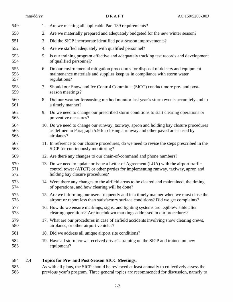
Are we meeting all applicable Part 139 requirements? 1.549
Are we materially prepared and adequately budgeted for the new winter season? 2.550
Did the SICP incorporate identified post-season improvements? 3.551
Are we staffed adequately with qualified personnel? 4.552
Is our training program effective and adequately tracking test records and development 5.553
of qualified personnel? 554
Do our environmental mitigation procedures for disposal of deicers and equipment 6.555
maintenance materials and supplies keep us in compliance with storm water 556
regulations? 557
Should our Snow and Ice Control Committee (SICC) conduct more pre- and post-7.558
season meetings? 559
Did our weather forecasting method monitor last year’s storm events accurately and in 8.560
a timely manner? 561
Do we need to change our prescribed storm conditions to start clearing operations or 9.562
preventive measures? 563
Do we need to change our runway, taxiway, apron and holding bay closure procedures 10.564
as defined in Paragraph 5.9 for closing a runway and other paved areas used by 565
airplanes? 566
In reference to our closure procedures, do we need to revise the steps prescribed in the 11.567
SICP for continuously monitoring? 568
Are there any changes to our chain-of-command and phone numbers? 12.569
Do we need to update or issue a Letter of Agreement (LOA) with the airport traffic 13.570
control tower (ATCT) or other parties for implementing runway, taxiway, apron and 571
holding bay closure procedures? 572
Were there any changes to the airfield areas to be cleared and maintained, the timing 14.573
of operations, and how clearing will be done? 574
Are we informing our users frequently and in a timely manner when we must close the 15.575
airport or report less than satisfactory surface conditions? Did we get complaints? 576
How do we ensure markings, signs, and lighting systems are legible/visible after 16.577
clearing operations? Are touchdown markings addressed in our procedures? 578
What are our procedures in case of airfield accidents involving snow clearing crews, 17.579
airplanes, or other airport vehicles? 580
Did we address all unique airport site conditions? 18.581
Have all storm crews received driver’s training on the SICP and trained on new 19.582
equipment? 583
Topics for Pre- and Post-Season SICC Meetings. 2.4584
As with all plans, the SICP should be reviewed at least annually to collectively assess the 585
previous year’s program. Three general topics are recommended for discussion, namely to 586

mm/dd/yy D R A F T AC 150/5200-30D
2-3
incorporate (1) changes to airport staff, equipment, runway chemicals, and airport clearing 587
procedures; (2) changes to air carrier ground deicing/anti-icing programs; and (3) “lessons 588
learned” from actual events encountered. The FAA recommends that before each winter 589
season, the SICC holds a series of meetings to prepare for and adequately budget for the 590
upcoming winter season. Two distinct meetings should be held; one focused on airport 591
clearing operations, and the other focused on air carrier ground deicing/anti-icing 592
programs. Each meeting should discuss any new topics not dealt with in past years, such as 593
new FAA aircraft ground deicing/anti-icing polices and new Federal, state, or local storm 594
water runoff regulations. 595
Topics Relative to Airport Snow Removal Operations Discussions. 2.4.1596
The following are topics normally covered: 597
Areas designated as Priority 1 areas, to include any new airfield infrastructure. 1.598
Clearing operations, follow-up airfield assessments and reporting actions to further 2.599
mitigate the potential for pilot and vehicular surface incidents or runway incursions. 600
Staffing requirements and qualifications (training) for snow crews and Snow Control 3.601
Center staff. 602
Update to the training program to close any ambiguity. 4.603
Streamline the decision-making process, the “chain-of-command” authority. 5.604
Response times to keep runways, taxiways, and apron areas operational, e.g., to rectify 6.605
problems encountered during previous storm events that hampered airport operations. 606
Communications, terminology, frequencies, and procedures with the airport traffic 7.607
control tower (ATCT), snow crews, and the Snow Control Center. 608
Monitoring and updating of surface conditions after a clearing operation and deicing or 8.609
sanding applications. 610
Issuance of NOTAMs and dissemination to air carrier and other airport tenants to meet 9.611
timely notification requirements. 612
Equipment inventory, including assessing the condition of snow control equipment, 10.613
scheduling repairs, and stocking spare parts. 614
Status of procurement contracts and specifications for new vehicles or equipment. 11.615
Preventive maintenance program for snow control equipment and maintenance and 12.616
calibration for friction testing equipment. 617
Status of procurement contracts and specifications for deicer-/anti-icer materials and 13.618
sand supply, including their storage before the first snowfall. 619
Validation of deicer certification letters from vendors. 14.620
Procedures for storm water runoff mitigation. 15.621
Snow hauling and/or disposal plan, including sites for dumping snow or positioning of 16.622
portable melter equipment for melting snow in place. 623
New runoff requirements for the containment and/or collection of deicing chemicals 17.624
and vehicle maintenance fluids and materials. 625

mm/dd/yy D R A F T AC 150/5200-30D
2-4
Changes to or the addition of new contract service for clearing aprons. 18.626
Topics Relative to Air Carrier Ground Deicing/Anti-icing Programs. 2.4.2627
The airport operator should act as a facilitator and arrange a meeting for the parties that 628
may be affected by airplane ground deicing plans, including those plans required of air 629
carriers operating under 14 CFR Part 121, Operating Requirements: Domestic, Flag, and 630
Supplemental Operations. These parties include airport management and consultants, the 631
air carriers, other airport users, corporate tenants, pilot representatives, and FAA Air 632
Traffic Control. The meeting should assess the impact of any airplane ground deicing 633
activities on airport operations and identify actions that can be taken by the various parties 634
to maximize the efficiency of operations during icing conditions. For example, the 635
committee may be able to identify the most effective locations for secondary deicing and 636
establish procedures for its implementation. At most airports, one meeting to discuss these 637
subjects before the start of the winter season should suffice. However, at other airports, 638
subsequent meetings may be necessary to assess the effectiveness of plans and to modify 639
them if necessary. These meetings typically address the following topics: 640
Assessment of all air carriers’ deicing programs from the previous year, including— 1.641
a. Reviewing airplane surface flow strategies. 642
b. Reviewing ground time and takeoff clearances after deicing. 643
c. Analyzing and adjusting to airplane deicing plans. 644
Actions needed to maximize efficiency of operations during icing conditions, 2.645
including— 646
a. Identifying locations for airplane deicing that use chemicals or infrared deicing 647
technology. 648
b. Planning taxi routes to minimize ground time. 649
c. Developing rates that control deiced departures. 650
d. Allocating departure slot capacities. 651
e. Determining airport deicing crew needs. 652
f. Verifying communication procedures between air traffic control and airplanes to 653
be deiced. 654
Any requirements for containment/collection of deicing/anti-icings. 3.655
Outlining a Snow and Ice Control Plan (SICP). 2.5656
A logical first step in writing the SICP is to identify and prioritize those aircraft movement 2.5.1657
areas to be cleared of snow and/or ice within certain times. Paragraphs 1.6 and 1.8 of this 658
advisory circular discuss airfield clearing priorities and clearance times. These parameters, 659
in turn, guide the airport operator in selecting the conditions that initiate activities, such as, 660
clearing operations, chemical applications, runway friction surveys, and other operations. 661
Chapter 3 provides information on weather forecasting and weather system technology as 662
one important tool useful as a head start for an appropriate response for winter storm 663
forecasts. 664

mm/dd/yy D R A F T AC 150/5200-30D
2-5
Next, the SICP must include instructions and procedures for handling the various types of 2.5.2665
winter storms encountered by the airport and how to notify airport users in a timely 666
manner of other than normal runway conditions, including, but not limited to: runway 667
closures, and when any portion of the movement area normally available to them is 668
covered by snow, slush, ice, or standing water. 669
When winter contaminants are present on airfield pavements, the airport operator must 2.5.3670
take steps to assess the conditions and take the appropriate steps for the contaminant type 671
Finally, the SICP should address special safety topics to minimize runway incursions 2.5.4672
during initial and follow-up clearing operations. Paragraph 2.7 of this chapter offers 673
guidance and recommendations for runway incursion mitigation. 674
Topics for Writing Instructions and Procedures for Winter Operations and 2.6675
Notification. 676
Part 139 airports are required to address the following topics in their SICP, and it is 677
recommended that all other airport operators address the same topics in their SICP. Each 678
topic provides a cross-reference for further clarification. 679
Prompt removal or control, as expeditiously as practicable, of snow, ice, and slush on 1.680
airfield pavements (see CHAPTER 4). 681
Positioning snow off airfield pavement surfaces so all airplane propellers, engine pods, 2.682
rotors, and wing tips will clear any snowdrift and snow bank as the airplane’s landing 683
gear traverses any portion of the movement area (see Figure 4-1, Chapter 4). 684
Selection and application of authorized materials for snow and ice control to ensure 3.685
they adhere to snow and ice sufficiently to minimize engine ingestion (see Chapter 4). 686
Timely commencement of snow and ice control operations. 4.687
Prompt notification in accordance with Part 139.339, Airport Condition Reporting, to 5.688
all air carriers using the airport when any portion of the movement area normally 689
available to them is less than satisfactorily cleared for safe operation by their aircraft 690
(see Chapter 5, Paragraphs 5.9, Requirements for Runway, Taxiway, and Apron and 691
Holding Bay Closures, and 5.7, Condition Reporting). In addition, all airplane 692
operators should be informed any time pavements are contaminated with ice, snow, 693
slush, or standing water. 694
Runway Incursion Mitigation and Operations During Non-Towered Air Traffic 2.7695
Control Periods. 696
The SICP should contain specific procedures for those periods when the ATCT is closed 2.7.1697
and for airports that do not have an ATCT (non-towered airport). Additionally the SICP 698
should contain specific procedures for unexpected situations, such as when “whiteout” 699
conditions occur while snow clearing crews occupy the runways. The following items 700
should be considered: 701

mm/dd/yy D R A F T AC 150/5200-30D
2-6
Surface clearing procedures must ensure snow removal operations will not create the 2.7.2702
possibility for a runway incursion after the runway reopens, for example, signage, 703
markings and lighting are clearly visible. 704
Although it is not required, airport operators should consider closing runways during snow 2.7.3705
clearing operations. For airport operators that choose to keep runways open during such 706
operations, the SICP should include procedures requiring continuous coordination among 707
the clearing crew and the SCC to ensure the equipment operators on runways are aware of 708
their surroundings. Snow removal equipment operators should monitor appropriate air 709
traffic control (ATC) or other frequencies for information on approaching or departing 710
airplanes. 711
The overlying air traffic control frequency should be monitored along with the local 2.7.4712
frequency by the airport’s Snow Control Center at all non-towered airports and at 713
airports where the ATCT has less than 24-hour operations. This should apply even if a 714
NOTAM has been issued closing the runway for snow clearing operations. Such 715
monitoring is especially important during marginal visual meteorological condition 716
(VMC) and instrument meteorological condition (IMC). 717
Note: The overlying air traffic facility may be enroute, terminal, or flight service. 718
Monitoring is recommended for snow crews to hear an airplane approaching and therefore 719
be able to clear the runway of personnel and equipment, if necessary. At times air traffic 720
control and /or the pilots may not be aware of a runway closure at the non-towered airport. 721
That is, sometimes a NOTAM is issued after an airplane becomes airborne and the pilot 722
did not receive the latest update, especially at an uncontrolled airfield. 723
Include special snow crew communication procedures for “whiteout” conditions at both 2.7.5724
towered and non-towered airports. 725
Include special snow crew communication procedures for occasions when a single 2.7.6726
equipment operator needs to return to the runway after a major clearing event. 727
Staff Training and Recordkeeping. 2.8728
The SICP should describe qualification criteria and training for individuals directly 729
involved in snow and ice control operations. The SICP should also outline recordkeeping 730
procedures for tracking employee progress in achieving training goals and objectives. The 731
SICP may specify that an implemented training program contain specific course material 732
for equipment drivers, staff working in the Snow Control Center, etc. Although airport 733
operators should develop their own training programs to address conditions at their 734
particular airports, the FAA recommends the programs contain the following minimum 735
components: 736
Use of formal classroom lectures, training films if available, and discussion periods to 1.737
teach the contents of the SICP to individuals who need to understand procedures in 738
detail. 739
Conduct of tabletop exercises that use miniature equipment on airfield layouts to 2.740
simulate operations. 741

mm/dd/yy D R A F T AC 150/5200-30D
2-7
Hands-on training for equipment operators on how their equipment works as well as 3.742
practice runs under typical operational scenarios. 743
Instruction on airfield familiarization that includes both day and night tours of the 4.744
airfield and ensures an understanding of all surface markings, signs, and lighting. 745
Instruction for all personnel on proper communication procedures and terminology. 5.746
This includes the special procedures to be followed during “whiteout” conditions and 747
when radio signal is lost between drivers and/or the ATCT. See FAA AC 150/5210-748
20, Ground Vehicle Operations on Airports, for guidance on communication 749
procedures for airport personnel. 750
Instruction for drivers on the proper procedures and communications to follow when 6.751
the ATCT is not operating or the airport has no ATCT. 752
Training in following runway closure criteria for personnel responsible for closing and 7.753
opening runways during snow events. This training is especially important for non-754
towered airports or part-time towered airports. 755
Instructions on what constitutes a runway incursion during snow removal operations. 8.756
Other Related Items. 2.9757
The implemented SICP needs to take into account how the document will integrate with 758
other airport plans, programs, and lease agreements. 759
Other Airport Plans and Programs. 2.9.1760
Although the SICP is a stand-alone plan, it should integrate with other airport plans and 761
programs to avoid conflicts and duplication of procedures and responsibilities. A few 762
examples of closely related plans/programs are the Airport Certification Manual, Airport 763
Emergency Plan, and the Storm Water Pollution Prevention Plan (for deicer runoff 764
mitigation). The FAA recommends the airport fire-fighting and rescue service receive a 765
copy of the SICP for their familiarization, especially so responders will know which 766
service roads will be closed. 767
Post Accident/Incident Recommendations. 2.9.2768
To address accidents or incidents that might occur during adverse weather conditions, the 769
SICP should contain procedures that ensure surface conditions occurring during the event 770
are properly inspected and documented. Additionally, the airport operator must not disturb 771
evidence on the runway until the appropriate Federal authority (FAA/National 772
Transportation Safety Board (NTSB) provides a release. To help the NTSB, the airport 773
operator should document the type and depth of contamination on the runway at the time 774
of the accident/incident, which should include conducting a runway friction assessment 775
and taking still and/or video photography. If wreckage is observed on the pavement, the 776
airport operator must not attempt to conduct testing in those areas that would disturb 777
evidence on the runway (see AC 150/5200-12, Fire Department Responsibility in 778
Protecting Evidence at the Scene of an Aircraft Accident). 779
Snow and Ice Control Contractors/Lease Agreements. 2.9.3780
The principle of ensuring safety of operations applies equally to lease holders and service 781
contractors hired to perform snow and ice control services. In particular, contractual 782

mm/dd/yy D R A F T AC 150/5200-30D
2-8
agreements should be clear and specific in terms of duties, procedures for snow and ice 783
control, responsibilities for communications and ground control, and other contingencies. 784
Service contractors and leaseholders should receive a copy of the latest airport SICP, not 785
necessarily the complete Airport Certification Manual. Contracted service providers are 786
recommended to have similar training as described in Paragraph 2.8. 787
Storm Water Runoff Regulations. 2.9.4788
Greater emphasis has been placed on mitigating the negative impacts associated with snow 789
clearing operations and equipment maintenance on bodies of water off the airport. The 790
SICP should be reviewed and modified, if necessary, to ensure it complements the 791
airport’s storm water discharging permit. That is, the SICP should help the airport operator 792
achieve compliance with Federal, State, and local environmental storm water runoff 793
regulations. 794
mm/dd/yy D R A F T AC 150/5200-30D
3-1
CHAPTER 3. FORECAST TECHNOLOGY FOR AIRPORT OPERATORS 795
Weather Forecasting. 3.1796
Appropriate responses to a winter storm event begin with accurate and timely weather 797
information. A reliable weather forecast not only enhances the effectiveness and efficiency 798
of any SICP, but it offers airport operators operational cost savings associated with snow 799
clearing tasks, chemical usage, and staffing. Airport operators should base their snow 800
clearing operations or preventive measures on weather forecasting that offers continuous, 801
up-to-date, and airport weather-related information. The FAA recommends that airport 802
operators select a weather forecasting approach that offers usable information to airport 803
users as well as to the airport operator. One such approach, the Weather Support to 804
Deicing Decision Making (WSDDM) System, is described below. 805
FAA Forecasting Research and Development for Airport Operators. 3.2806
The FAA Aviation Weather Research Program began research in the 1990s to fully 807
understand the safety problems faced during winter storm events and to improve decision 808
making by airport operators and air carrier ground operations during these events. The 809
research resulted in the Weather Support to Deicing Decision Making (WSDDM) System, 810
an integrated display system that depicts accurate, real-time determinations of snowfall 811
rate, accumulations and their liquid equivalents, temperature, humidity, wind speed, and 812
direction of storm events. 813
Weather Support to Deicing Decision Making (WSDDM) System. 3.2.1814
The WSDDM System is an automated system that analyzes and forecasts short-term winter 815
weather conditions within the airport vicinity. The data inputs to the system are provided 816
by snow gauges; weather radars, such as Doppler; surface weather stations; and National 817
Weather Service Aviation Routine Weather Report (METAR) data from Automated 818
Surface Observing Systems (ASOS). All data are processed by software algorithms to 819
produce a graphical and text depiction of current weather conditions and a 1-hour forecast 820
of expected snowfall rate and accumulation at the airport. The displayed analyses and 821
forecasts can be easily understood by most users. The graphical data can be generated and 822
displayed on a local computer or viewed online. The system has been effective at major 823
U.S. airports. 824
The basic version of the WSDDM system, known as Basic WSDDM, is for 3.2.1.1825
unidirectional storm fronts. The system has a single snow gauge with a 826
computer display of the current and historical liquid equivalent snowfall rates 827
and accumulation. Airports that routinely encounter multiple storm fronts 828
should use two or more snow gauges. Figure 3-1 shows one type of snow 829
gauge used by WSDDM. Figure 3-2 illustrates the Basic WSDDM schematic 830
for a unidirectional storm configuration. 831
WSDDM systems must comply with the equipment performance and 3.2.1.2832
installation requirements described in Society of Automotive Engineers (SAE) 833
Aerospace Standard (AS) 5537, Weather Support to Deicing Decision Making 834

mm/dd/yy D R A F T AC 150/5200-30D
3-2
(WSDDM), Winter Weather Nowcasting System. The SAE specification is 835
available for purchase at http://www.sae.org. 836
Safety and Operational Benefits. 3.2.2837
The WSDDM system provides current and 1-hour NOWCAST forecasts (current 838
conditions) of snow bands and surface weather conditions on the airport and the 839
surrounding 125-mile (200-km) vicinity. The display is optimized to allow airport 840
operators and air carriers to understand (typically within 1 minute) the current weather 841
conditions at the airport and in the surrounding region. This capability allows for more 842
rapid and appropriate decision making during winter storms with minimal impact on 843
airport resources and staff workload. 844
Figure 3-1. Single Alter Wind Shield Type 845
846

mm/dd/yy D R A F T AC 150/5200-30D
3-1
Figure 3-2. Schematic of Unidirectional Storm WSDDM Configuration 847
848
Benefits to Airport Operators. 3.2.2.1849
Users of WSDDM have reported various operational and cost-saving benefits. 850
WSDDM optimizes runway clearing operations by providing airport operators 851
more accurate information about when a snow band will affect the airport. 852
Accurate timing saves on anti-icers because it allows crews to apply them 853
according to the manufacturer’s recommended lead times. In terms of 854
managing crew workloads, WSDDM determines gaps in storm events, which 855
can be used to change crew shifts, take rests, and refill chemical trucks, sand 856
spreaders, and other equipment. Airport operators are also able to more 857
accurately determine when the airport can resume normal operations by 858
examining the radar loops and storm tracks and watching storm trends. By 859
examining the storm tracks, users can make fairly accurate 3- to 4-hour 860
forecasts of snow onset, which, in turn, allow airport operators to prepare more 861
appropriately for winter storms. 862
Real-Time Liquid Content Forecast. 3.2.2.2863
A key safety element of the WSDDM system is the use of one or more 864
precision snow gauges. These snow gauges provide real-time estimates of the 865
liquid equivalent snowfall rate for every minute. This measurement is key to 866
air carrier deicing operations because the deicing community has shown the 867
liquid equivalent snowfall rate is the key factor leading to the failure of 868
mm/dd/yy D R A F T AC 150/5200-30D
3-2
deicing/anti-icing fluids. The current National Weather Surface METAR 869
stations do not provide this data. Instead, METAR provides hourly snow 870
intensity estimates based on visibility. Snow intensity estimates based on 871
visibility have been shown to be misleading when wet snow, heavily rimed 872
snow (snow that has accreted significant amounts of cloud droplets), and snow 873
containing single crystals of compact shape (nearly spherical) occur. 874
Researchers define the hazard as high-visibility/high-snowfall rate conditions. 875
Recent examination of five of the major airplane ground deicing accidents 876
showed that high visibility-high snowfall rate conditions were present during a 877
number of these accidents. All of the accidents had nearly the same liquid 878
equivalent rate of 0.1 inch/hour (2.5 mm/hour), but widely varying visibilities. 879
The WSDDM System was designed to address this safety concern by including 880
snow gauges to measure liquid equivalent snowfall rate every minute. 881
Forecasting Runway Surface Conditions. 3.3882
One proven method of forecasting the surface conditions of runways is to use runway 883
surface condition sensors (RSCS). Two basic types of RSCS are in use today, namely in-884
pavement stationary sensors and vehicle-mounted infrared sensors. The safety benefit of 885
RSCS is their predictive capability for proactive anti-icing decision making. Since the 886
temperature of pavements lag behind air temperature, the use of air temperature to infer 887
surface conditions is imprecise. Therefore, the use of air temperature is never 888
recommended because it frequently leads to misinformation about the true behavior of 889
pavement surfaces. This inaccuracy can result in inappropriate airfield clearing operations 890
or poorly timed preventive measures. At its worst, this misinformation might result in 891
delays that allow ice to bond to paved surfaces, the hardest condition to rectify. With the 892
exception of freezing rain, ice will not form on pavements unless the pavement 893
temperature itself reaches the freezing point. Therefore, knowledge of the direction and 894
rate of temperature change within a pavement structure provides the predictive capability 895
as to when to expect the formation of ice. The predictive nature of RSCS is particular 896
valuable as it ensures the timely application of anti-icing (or deicers) chemicals, which 897
provides a cost savings in chemicals, and helps crews make appropriate chemical 898
selections to prevent, weaken, or disbond ice or compacted snow from paved surfaces. 899
Airport operators have at their disposal in-pavement RSCS at pre-determined sites and 900
mobile RSCS that are hand-held or vehicle-mounted to evaluate any pavement. 901
Stationary Runway Weather Information Systems. 3.3.1902
These stationary sensors provide only site-specific pavement and air temperature trends, 903
dew point temperature, chemical strength, and other atmospheric weather conditions at the 904
installation sites. Sensor information is generally disseminated via a central computer to 905
airport users. An added bonus of in-pavement RSCS is their ability to predict when 906
previously applied chemicals have been diluted sufficiently to require reapplication of 907
chemicals. The FAA recommends that in-pavement RSCS comply with the performance 908
and installation requirements of SAE Aerospace Recommended Practice (ARP) 5533, 909
Stationary Runway Weather Information System (In-pavement). The SAE specification is 910
available for purchase at http://www.sae.org. 911

mm/dd/yy D R A F T AC 150/5200-30D
3-3
Mobile Infrared Surface and Ambient Temperature Sensor Systems. 3.3.2912
These vehicle-mounted sensors provide pavement and air temperatures at any desired 913
airfield pavement location. Information is disseminated directly to the viewer or driver of 914
the vehicle-mounted units. The FAA recommends that mobile RSCS comply with the 915
performance requirements of SAE ARP 5623, Mobile Digital Infrared Pavement Surface, 916
Ambient Air and Dew Point Temperature Sensor System. The SAE specification is 917
available for purchase at http://www.sae.org. 918

mm/dd/yy D R A F T AC 150/5200-30D
3-4
This page intentionally left blank.919

mm/dd/yy D R A F T AC 150/5200-30D
4-1
CHAPTER 4. SNOW CLEARING OPERATIONS AND ICE PREVENTION 920
Introduction. 4.1921
Contaminants on a runway impede airplane acceleration by absorbing energy in 922
compaction and displacement, and by impinging on parts of the airplane after being kicked 923
up by the tires. For airplanes decelerating, slush, snow, and standing water-covered 924
pavements and, especially iced surfaces, hamper deceleration rates due to a reduction in 925
the friction coefficient of the runway and the potential for hydroplaning. Large chunks of 926
ice, from refreezing snow or slush, or deposits from aircraft gear created during landings, 927
can cause severe damage to tires, engines and airframes. Wet snow, slush, and standing 928
water can cause structural damage from spray impingement or by engine ingestion, which 929
can affect acceleration capability. The recommended maximum depth for takeoff 930
operations for slush and water is ½ inch (13mm) unless the airplane’s AFM shows greater 931
depths to be safe. (See AC 25-31, Takeoff Performance Data for Operations on 932
Contaminated Runways.) Consequently, these runway surface contaminants should be 933
minimized to maintain safe landing, takeoff, and turnoff operations. For these reasons, 934
snow clearing operations for Priority 1 runway(s), taxiway connectors, and taxiways to the 935
terminal(s) should start as soon as practicable after snowfall or icing begins. One prime 936
goal is to take the appropriate measures so snow in its various forms, such as slush or 937
frozen water, does not bond to the pavement. Dry snow falling on cold dry pavements will 938
generally not adhere and may be blown off by wind or airplane operations or removed by 939
brooming operations. In such conditions, only brooming may be needed to prevent the 940
formation of compacted snow tracks. Snow fences may be of use to airports that primarily 941
experience dry snowfalls. Wet snow, however, cannot be blown off the pavement and will 942
readily compact and bond to it when run over by airplane wheels. Consequently, the 943
airport operator will need to implement different clearing and/or preventive measures for 944
wet snow than those used for dry snow conditions. When measures are taken, the airport 945
operator’s Snow Control Center (SCC) must (1) maintain close coordination with the 946
ATCT and the Flight Service Station (FSS) or UNICOM to ensure prompt and safe 947
responses to winter storm events and (2) inform the users of the airport when less than 948
satisfactory conditions exist. 949
Snow Clearing Principles. 4.2950
Winter conditions and rates of accumulations of precipitation vary widely from airport to 951
airport. However, there are some basic guidelines that apply to all airports that should be 952
followed as closely as possible. The airport operator should notify airport users promptly 953
and issue a NOTAM advising users of unusual airport conditions. Wind speed and 954
direction, available equipment, and local conditions that may require special equipment 955
and techniques, collectively determine the snow clearing procedures for the airport’s SICP. 956
The following guidance offers a generic outline for writing the SICP that covers terminal 957
apron environment-related items, runway/taxiway-related items, and areas with special 958
surface material such as Engineered Material Arresting Systems. 959

mm/dd/yy D R A F T AC 150/5200-30D
4-2
Terminal Apron Suggested – Clearing Objectives. 4.2.1960
Accumulations of snow and slush, snow tracks, and thin layers of ice on aprons and 961
airplane parking areas, including holding bays, can make for safety hazards. The SICP 962
should contain measures to mitigate at least the following five common situations: 963
Slick Apron Surfaces. Apron equipment and apron personnel operating on slick or icy 1.964
apron surfaces lack sufficient traction to start, stop, or even remain in place when 965
encountering jet exhaust from surrounding airplanes. Maintaining good traction is 966
critical to the safety of personnel, equipment, and airplanes. 967
Increased Airplane Engine Thrust. Pilots of parked or holding airplanes must apply 2.968
increased engine thrust to break away, maneuver, and taxi under adverse apron surface 969
irregularities, such as frozen ruts formed by tire tracks. The resultant excessive engine 970
blast necessary to overcome such obstacles may damage other airplanes, apron 971
equipment, or apron personnel. 972
Obscured Taxiway Signage. The clearing of snow from apron areas must not be 3.973
performed in a way that partially or completely covers taxiway signs with plowed 974
snow. Observing this precaution will reduce the risk of runway incursions. 975
Obscured Terminal Visual Aids. The obscuration of normally visible surface 4.976
markings or obliterated sign messages could make maneuvering on aprons difficult 977
and slow. Pilots, unable to see these visual aids, are hard pressed to judge direction and 978
taxiing clearances. 979
Snow Stockpiles Adjacent to Airplane Operating Areas. Airport operators should 5.980
exercise care when moving snow from the aprons and terminals toward taxiways and 981
runways. Depending on the amount of snow cleared and the size of the apron, apron 982
signage directing pilots toward the runway could become obscured (covered with 983
snow), and the resulting height of snow stockpiles could cause a clearance issue 984
between taxiing airplanes and the snow stockpile. Airports that experience heavy 985
snowfalls and have large aprons with limited space for stockpiling snow should 986
consider operating snow melters or hauling snow away. 987
Runway and Taxiway Suggested Clearing Objectives. 4.2.2988
The following guidance is intended to show efficient use of various equipment to optimize 989
snow clearing operations. Some types of equipment may not be appropriate for some 990
airports. Equipment and procedures used must be determined based on many factors, 991
including but not limited to climate, number and types of operations, and amount of annual 992
snowfall. 993
Focus runway snow clearing operations on keeping the entire primary 4.2.2.1994
runway(s), as near as practicable, bare from snow accumulations or ice 995
buildup. Depending on the precipitation rate, the time required to clear the full 996
width of the runway may result in additional accumulation, and thus less 997
braking capability, on the critical center portion. In such a case, concentrating 998
on the center portion of the runway, during the initial clearing operations can 999
result in greater safety. The minimum width required will vary by airplane 1000
type, but is generally 100’ for transport category airplanes. The airport 1001
operator should check with airport users regarding their minimum runway 1002
width requirements. Additionally, the airport operator must keep in mind that 1003

mm/dd/yy D R A F T AC 150/5200-30D
4-3
the entire width of runway is still usable and must be safely maintained. This 1004
means that while contaminant depths may vary from the center cleared portion 1005
to the remaining portions of the runway, the condition of the outlying portions 1006
must not present a hazard. Use sweepers or brooms initially to keep the 1007
primary runway or its center portion, as near as practicable, bare of 1008
accumulations. Also, when snow has melted or ice begins to separate from the 1009
pavement due to the action of chemicals, sweepers or brooms should be used 1010
to remove the residue. As soon as snow has accumulated to a depth that cannot 1011
efficiently be handled by the sweepers or brooms, displacement plows and 1012
rotary plows (snow blowers) should be used as follows. 1013
1. Use displacement plows, in tandem if more than one, to windrow snow 1014
into a single windrow that can be cast over the edge of runway lights by a 1015
rotary plow. 1016
2. For runways or other paved areas with in-pavement surface condition 1017
sensors, remove any snow or ice that affects the performance of the remote 1018
sensors. 1019
3. Regarding the use of displacement plows, ice and snow will always melt 1020
around runway centerline and touchdown zone light assemblies. However, 1021
under cold temperatures, ice rings, termed “igloos,” tend to form around 1022
them. In order to prevent damage to lights, use appropriate polyurethane 1023
cutting edges or shoes and casters on plow moldboards and on the front of 1024
rotary plows. 1025
4. Rotary plows should throw snow a sufficient distance from 1026
runways/taxiways edges so adequate clearance is available between 1027
airplane wings and engine nacelles and the cast snow banks. Figure 4-1 1028
shows desired maximum snow height profiles, which are based on airplane 1029
design groups. 1030
All drivers must maintain a safe distance between equipment operating in 4.2.2.21031
echelon (i.e., V-formation, close wing formation) in order to avoid accidental 1032
contact or accidents (See Figures 4-3, 4-4, and 4-5). 1033
Obscured visual aids—in particular, in-pavement and edge lights, taxiway 4.2.2.31034
markings, runway markings (such as touchdown marking), airport guidance 1035
signs, and runway end identification lights (REIL), precision approach path 1036
indicator (PAPI) or visual approach slope indicator (VASI) — need to be 1037
maintained free of snow and ice. 1038
A covering of snow and ice or drifts may affect visual and electronic 4.2.2.41039
NAVAIDs. Any snow or ice that affects the signal of electronic NAVAIDs 1040
should be removed. When clearing with rotary plows and displacement plows, 1041
special procedures need to take into account the location of all NAVAIDs, 1042
especially to protect the guidance signal of instrument landing systems (ILS). 1043
The SICP needs to address the following situations: 1044
4.2.2.4.1 Glide slope critical ground areas along the runway require that snow depths be 1045
limited in height to prevent signal loss or scattering. Figure 4-2 provides 1046

mm/dd/yy D R A F T AC 150/5200-30D
4-4
graphic representations of the glide slope ground snow clearance areas with 1047
prescribed snow depth limitations according to type of facility and aircraft 1048
approach category. When snow depths exceed the specified depth limitations, 1049
minima are raised to the “localizer only” function until the conditions revert or 1050
are corrected. Two consecutive pilot reports of glide slope signal malfunctions 1051
generally result in raised minima (a NOTAM must be issued by the owner of 1052
the NAVAID). A few additional points should be considered. First, the 200-1053
foot width dimension adjacent to the threshold might be wider for an antenna 1054
mast placed further out (see FAA Order 6750.49, Maintenance of Instrument 1055
Landing System (ILS) Facilities). Second, the snow clearance areas illustrated 1056
in the figures are minimal in size. Third, snow clearing activities should not 1057
allow snow banks, mounds, or ridges exceeding 2 feet to be placed along the 1058
edges of the prescribed snow clearance areas. Fourth, snow banks should not 1059
be placed off the approach ends of runways, especially for CAT II/III 1060
operations. 1061
Note: Snow banking operations need to take into account the guidance in 1062
Figure 4-1. 1063
4.2.2.4.2 Visibility of signs (legibility) and lights should be maintained by certain 1064
prescribed clearing techniques or by performing post-clearing maintenance. 1065
Maintaining visibility can be better achieved by taking into account wind 1066
directions. For example, in crosswind conditions, cast in the downwind 1067
direction. Figure 4-3 through Figure 4-5 provides general guidance. 1068
4.2.2.4.3 The snow depth height limitations noted in Figure 4-2 do not take into 1069
consideration airplane characteristics. That is, at some airports, airplane 1070
characteristics, such as engine clearances, may dictate lower snow banks than 1071
shown in Figure 4-2. The objective here is prevention by avoiding the 1072
introduction of hazardous snow banks, drifts, windrows, and ice ridges that 1073
could come into contact with any portion of the airplane wing or nacelle 1074
surface. 1075
If the airport’s operation involves the use of snow banks, their height profiles 4.2.2.51076
should be compatible with NAVAID ground requirements and offer sufficient 1077
clearance between airplane wings and engine nacelles to avoid structural 1078
damage to jet and propeller airplanes. Figure 4-1 shows maximum allowable 1079
snow height profiles, which are based on airplane design groups (see AC 1080
150/5300-13, Airport Design, for airplane design group categories.) Snow 1081
banking along terminal or cargo aprons likewise should comply with Figure 1082
4-1 to prevent operational problems caused by ingestion of ice into turbine 1083
engines or by propellers striking the snow banks. Appendix B, which used 1084
numerous airplane models, was used to develop criteria for Figure 4-1. 1085
Upon completion of snow clearing operations, runway assessments and 4.2.2.61086
friction measurements should be accomplished to determine the effectiveness 1087
of the snow clearing operation. See Chapter 5 for additional guidance. 1088

mm/dd/yy D R A F T AC 150/5200-30D
4-5
If the runway pavement temperature is warm enough for snow to compact and 4.2.2.71089
bond, or if freezing rain is forecasted, approved anti-icing chemicals and/or 1090
heated sand should be applied prior to the start of precipitation or as soon as 1091
precipitation starts. Some airport operators prefer to apply deicing chemicals 1092
rather than anti-icing chemicals for different weather conditions. Paragraph 4.6 1093
provides a listing of approved fluid and solid material specifications. 1094
All snow removal units operating in aircraft movement areas must maintain 4.2.2.81095
radio communication with the ATCT, if one exists, or be under the direct 1096
control of a designated supervisor who in turn is in direct communication with 1097
the ATCT. 1098
High-speed runway turnoffs require the same attention for ice and snow 4.2.2.91099
control and removal as runways. These turnoffs should offer sufficient 1100
directional control and braking action for airplanes under all conditions. 1101
Accident data clearly illustrate that poor attention to high-speed runway 1102
turnoffs contributes to veer offs. 1103
Joint-use airports with military operations may have arresting barriers located 4.2.2.101104
near the end of the runway or at the beginning of the overrun areas. Great care 1105
should be taken in clearing snow from the barriers. Barriers located on the 1106
runway should be deactivated and pendants removed prior to snow removal 1107
operations. Snow should be removed to the distance required for effective run-1108
out of the arresting system. 1109
Engineered Material Arresting System (EMAS) Suggested Clearing Objectives. 4.2.31110
EMAS installed at airports require special attention as relates to removal of 4.2.3.11111
contaminants. Most are designed to be mechanically or manually cleared of 1112
contaminants. The manufacture specifications should be reviewed in order to 1113
determine what types of equipment are compatible with the EMAS bed and 1114
recommended clearing procedures and/or limitations. See FAA Advisory 1115
Circular 150/5220-22, Engineered Materials Arresting Systems (EMAS) for 1116
Aircraft Overruns, for additional guidance. 1117
Identify compatible deicing agents and the equipment, tools, or process for 4.2.3.21118
application. 1119

mm/dd/yy D R A F T AC 150/5200-30D
4-6
Figure 4-1. Snow Bank Profile Limits Along Edges of Runways and Taxiways with the 1120
Airplane Wheels on Full Strength Pavement (see Figure 4-2 guidance) 1121
1122
1123
1124
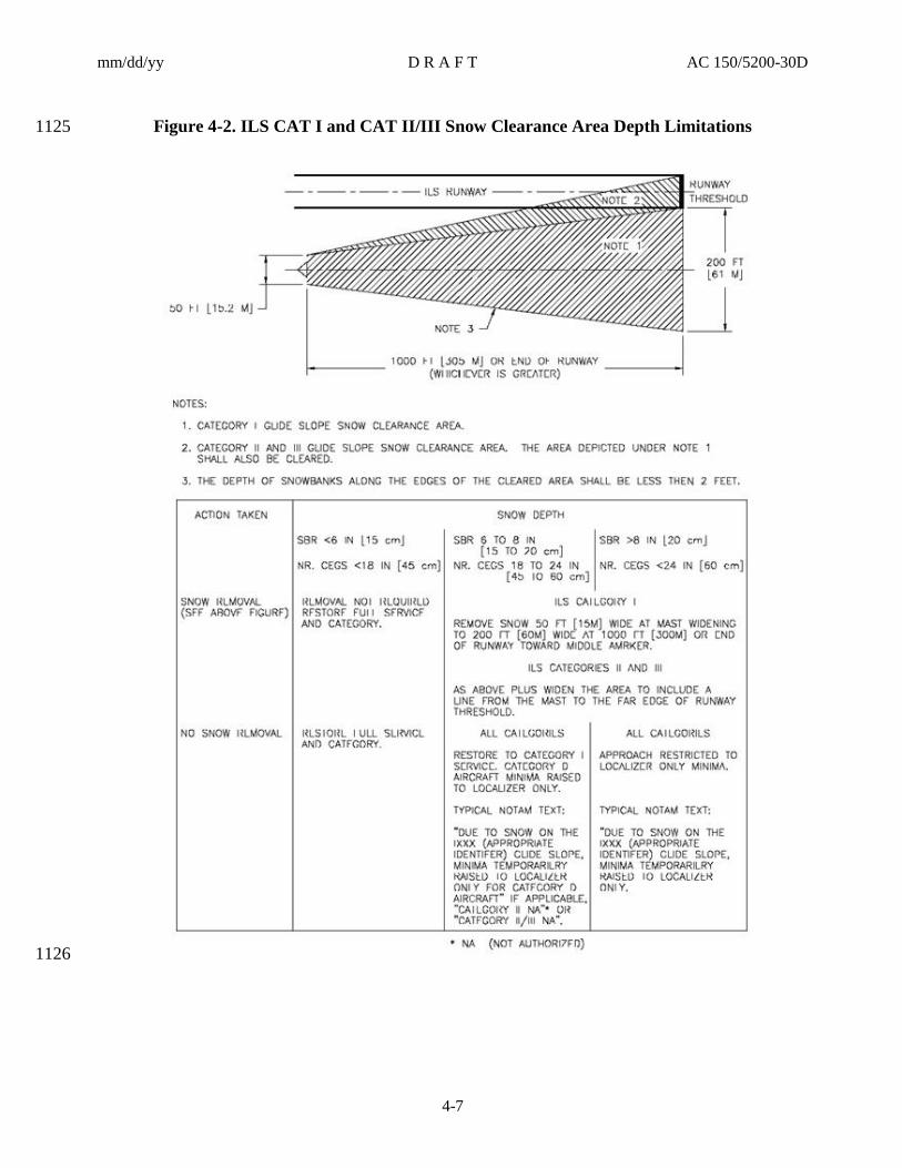
mm/dd/yy D R A F T AC 150/5200-30D
4-7
Figure 4-2. ILS CAT I and CAT II/III Snow Clearance Area Depth Limitations 1125
1126
mm/dd/yy D R A F T AC 150/5200-30D
4-8
Figure 4-3. Possible Team Configuration with Perpendicular Wind 1127
1128
Figure 4-4. Possible Team Configuration During Light Snowfall with Parallel or Calm Wind 1129
1130
1131
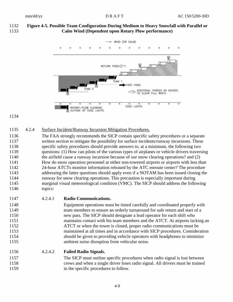
mm/dd/yy D R A F T AC 150/5200-30D
4-9
Figure 4-5. Possible Team Configuration During Medium to Heavy Snowfall with Parallel or 1132
Calm Wind (Dependent upon Rotary Plow performance) 1133
1134
Surface Incident/Runway Incursion Mitigation Procedures. 4.2.41135
The FAA strongly recommends the SICP contain specific safety procedures or a separate 1136
written section to mitigate the possibility for surface incidents/runway incursions. These 1137
specific safety procedures should provide answers to, at a minimum, the following two 1138
questions: (1) How can pilots of the various types of airplanes or vehicle drivers traversing 1139
the airfield cause a runway incursion because of our snow clearing operations? and (2) 1140
How do snow operation personnel at either non-towered airports or airports with less than 1141
24-hour ATCTs monitor information released by the ATC enroute center? The procedure 1142
addressing the latter questions should apply even if a NOTAM has been issued closing the 1143
runway for snow clearing operations. This precaution is especially important during 1144
marginal visual meteorological condition (VMC). The SICP should address the following 1145
topics: 1146
Radio Communications. 4.2.4.11147
Equipment operations must be timed carefully and coordinated properly with 1148
team members to ensure an orderly turnaround for safe return and start of a 1149
new pass. The SICP should designate a lead operator for each shift who 1150
maintains contact with his team members and the ATCT. At airports lacking an 1151
ATCT or when the tower is closed, proper radio communications must be 1152
maintained at all times and in accordance with SICP procedures. Consideration 1153
should be given to providing vehicle operators with headphones to minimize 1154
ambient noise disruption from vehicular noise. 1155
Failed Radio Signals. 4.2.4.21156
The SICP must outline specific procedures when radio signal is lost between 1157
crews and when a single driver loses radio signal. All drivers must be trained 1158
in the specific procedures to follow. 1159

mm/dd/yy D R A F T AC 150/5200-30D
4-10
Airfield Signage and Lights. 4.2.4.31160
Airfield signs must be kept clean of plowed or cast snow to maintain the 1161
legibility of signage. Priority should be given to lights and signs associated 1162
with holdlines, direction and location signs, and ILS critical areas. Common 1163
methods to remove snow from signs include using a truck mounted with an air-1164
blast unit, spraying the faces of signs with an approved liquid deicer, or hand 1165
shoveling. 1166
Low Visibility and Whiteouts. 4.2.4.41167
It is of utmost importance to maintain visual contact with your surroundings 1168
during snow clearing operations, especially for operations in an echelon 1169
formation. The SICP must specify procedures to follow if visibility suddenly 1170
drops to near zero or whiteout conditions exist while clearing operations are in 1171
progress. For example, the airport operator may require that all equipment stop 1172
immediately with all drivers radioing in their positions to the designated 1173
supervisor or to ATCT for runway evacuation instructions. 1174
Driver Fatigue. 4.2.4.51175
Consideration should be given to monitoring the “windshield time” of drivers 1176
(length of shift) operating snow removal equipment because operator fatigue 1177
could become a contributing factor for runway incursions. In response, some 1178
airport operators have implemented limits on driver operating hours. 1179
Controlling Snow Drifts. 4.31180
Preventing snow from drifting onto operational areas at airports receiving severe winter 1181
storms reduces the duration and frequency of snow clearing operations. Two methods for 1182
controlling drifts are described below. 1183
Snow Fences. 4.3.11184
Snow fences that are properly designed and located can reduce windblown snow across 1185
airfields. Experience at a particular airport is the most helpful in determining optimum 1186
locations for snow fences. The following precautions and guidance are provided: 1187
Prior to any installations, the airport operator must contact the nearest Air 4.3.1.11188
Traffic technical operations control center for any planned installations in the 1189
vicinity of a NAVAID system. Failure to remove snow or the introduction of 1190
snow in areas adjacent to NAVAID systems could result in erroneous signal 1191
guidance or facility shutdown. 1192
Snow fences should be located upwind of the area to be protected. 4.3.1.21193
A study conducted by the U.S. Department of Agriculture showed 12-foot 4.3.1.31194
(3.7-m) high fences were generally most effective. Shorter heights can be and 1195
usually are necessary on airport property, since snow fences must not penetrate 1196
critical surfaces, Runway or Taxiway Safety Areas, or Object Free Areas, as 1197
defined in AC 150/5300-13. 1198

mm/dd/yy D R A F T AC 150/5200-30D
4-11
Snow Trenches. 4.3.21199
Snow trenches that catch and store drifting snow have been used at times by airports with 1200
heavy snowfalls. This approach is considered an expedient way to control snow from 1201
drifting after it has been cleared to the edge of the runway. Multiple trenches spaced 1202
longitudinally about 10 feet (3 m) apart running parallel to the runway can store more 1203
snow. A trench should be excavated no closer than 50 feet (15 m) from the runway. Figure 1204
4-6 illustrates typical snow trench formation relative to wind direction. 1205
Figure 4-6. Typical Snow Trench Dimensions 1206
1207
Snow Disposal. 4.41208
The SICP should also specify how and where large quantities of snow are to be disposed. 1209
Two common approaches are as follows: 1210
Melting Pits or Portable Melters. 4.4.11211
A variety of snow and ice melters are in use at various airports that deal with large snow 1212
falls and for the environmental mitigation of deicer chemicals. This approach may be an 1213
economical viable solution to expensive snow hauling services. In contrast, melters 1214
eliminate the need for convoys of trucks to enter and exit secured airport areas, i.e., a lesser 1215
security and surface incident/runway incursion risk. Environmentally, contaminates within 1216
the snow are retained for proper disposal. Portable melters in comparison to melting pits 1217
can be conveniently setup at various melting sites instead of having to transport collected 1218
snow to a designated snow hauling area(s). 1219
Identifying Disposal Sites. 4.4.21220
If there is insufficient space for storing snow near areas to be cleared and no melting or 1221
flushing means are available, hauling to a disposal site may be necessary. If deemed 1222
necessary, the disposal site should be selected before winter sets in and identified in the 1223
SICP. The selection process should at least consider the following: 1224

mm/dd/yy D R A F T AC 150/5200-30D
4-12
disposal sites do not compromise airplane operations, airport NAVAIDs, airport 1.1225
traffic, and ATCT operations such as ATCT line-of-sight requirements; 1226
sites have adequate drainage capability; and 2.1227
sites offer, if required, environmental mitigation of captured chemicals. 3.1228
Methods for Ice Control and Removal. 4.51229
Preventing a bond from occurring between ice and the pavement surface is always 4.5.11230
preferred over the mechanical removal or melting of the bonded ice. Appendix C provides 1231
the characteristics of ice and other forms of snow and other details as it relates to handling 1232
their removal. Paragraph 4.6 provides the FAA-recommended chemical specifications for 1233
approved airside anti-icer and deicer products. Prevention is achieved by applying 1234
approved anti-icing chemicals to pavements with temperatures expected to go below 32° F 1235
(0° C). Fluid anti-icing products instead of solid anti-icing products are recommended 1236
since the liquid form is more effective in achieving uniform distributions and improved 1237
chemical-adhesion to the pavement surface. The primary drawback of solid chemicals on 1238
cold pavements is their inability to adhere properly to the surface, which can lead to their 1239
being windblown or scattered about. 1240
Once the ice has bonded to the pavement surface, the airport operators may use approved 4.5.21241
deicers to melt through the ice pack to break up or weaken the ice bond; increase the 1242
frictional characteristics of the surface, for example, by applying heated sand; or use 1243
mechanical means, such as plowing with under-body scrapers or scarifying the ice surface 1244
to break the ice packs. The type of brooms used to remove a layer of ice is important since 1245
in some cases the broom may actually “polish” the ice, thus reducing traction. Steel bristles 1246
are better than poly bristles since one “cuts” the ice surface while the other “flips” snow. 1247
Paragraph 4.7 provides guidance on methods to improve the frictional characteristics of 1248
surfaces, and Paragraph 4.8 provides the FAA sand gradation criteria for airfield usage. 1249
Approved Chemicals. 4.61250
Airside Chemicals. 4.6.11251
The FAA either establishes approval specifications or, upon acceptance, references the 1252
specifications of professional associations, such as SAE Aerospace Material Specifications 1253
(AMS), and the U.S. military (MIL-SPEC). The approved airside chemicals for runway 1254
and taxiway applications are fluid and solid products meeting a generic SAE or MIL 1255
specification. These specifications require vendors to provide airport operators with a lab 1256
certification stating the chemical conformed to the applicable specification and a material 1257
safety data sheet (MSDS) for handling the product. With the increased accountability 1258
placed on airport operators to manage deicing/anti-icing chemical runoff, they should 1259
request vendors to provide certain environmental data. These data consist of information 1260
on pollutants the Environmental Protection Agency and the State Department of Natural 1261
Resources request of the airport operators in their discharge reporting requirements. 1262
Typically, the information includes percent product biodegradability, biochemical oxygen 1263
demand (BOD5), chemical oxygen demand (COD), pH, presence of toxic or hazardous 1264
components, if any, and remaining inert elements after application. MSDSs provide 1265

mm/dd/yy D R A F T AC 150/5200-30D
4-13
measures on how to secure large product spills and a 24-hour toll-free emergency phone 1266
number. While these fluid and solid specifications cover technical requirements for 1267
deicing/anti-icing products, they do not address the compatibility issue of combining 1268
products during operations. Airport operators, therefore, should query manufacturers about 1269
the safe and proper use of concurrently applying multiple deicers/anti-icers. The FAA-1270
approved airside chemical specifications, which may be restricted by state or local 1271
environmental regulations, are as follows: 1272
Fluid Deicer/Anti-icers. 4.6.1.11273
The approved specification is the latest edition of SAE AMS 1435, Fluid, 1274
Generic Deicing/Anti-icing, Runways and Taxiways. Approved products 1275
include glycol-based fluids, potassium acetate base, and potassium formate-1276
based fluids. The SAE specification is available for purchase at 1277
http://www.sae.org. Application rates for a specific product are based on 1278
manufacturer recommendations. In terms of material cost-savings, less product 1279
is used by anti-icing operations than by deicing operations. 1280
Solid Deicer/Anti-icer. 4.6.1.21281
4.6.1.2.1 Generic Solids. 1282
The approved specification is the latest edition of SAE AMS 1431, Compound, 1283
Solid Runway and Taxiway Deicing/Anti-icing. Approved solid compounds 1284
include airside urea, sodium formate, and sodium acetate. It is noted that, in 1285
comparison to airside urea, sodium formate and sodium acetate products 1286
continue to be effective for much colder pavement temperatures. The urea 1287
deicing function is practical only at temperatures above approximately 15° F (-1288
10° C) because of the decreasing melting rates below this temperature value. 1289
The decreasing melting rate is a result of urea’s eutectic temperature, defined 1290
in Paragraph 1.12.8, which is approximately 11° F (-12° C). However, the 1291
presence of solar radiation assists urea in the melting action. Pavement surface 1292
temperature and ice thickness determine the urea application rate. Application 1293
rates for a specific product are based on manufacturer recommendations. 1294
4.6.1.2.2 Airside Urea (or “Carbamide”). 1295
The approved specifications are the latest edition of SAE AMS 1431, 1296
Compound, Solid Runway and Taxiway Deicing/Anti-icing, and MIL SPEC 1297
DOD-U10866D, Urea-Technical. Agricultural grade urea that meets any of 1298
these specifications, called airside urea, is acceptable. This nontoxic solid 1299
white chemical comes in either powder or “shotted” (“prilled”) form. The latter 1300
form’s shape is small spheres of about l/l6 inch (1.5 mm) in diameter. Both 1301
forms are primarily for deicing, where powdered urea is frequently mixed with 1302
sand. Hot mixtures of powder or “shotted” urea and sand are used by airport 1303
operators for two purposes: (1) immediate increase in braking action and (2) 1304
retention of chemical over the pavement area until it initially dissolves some of 1305
the ice and then melts the remainder. Table 4-1 provides guidance on 1306
application rates in relation to pavement temperature and ice thickness. 1307
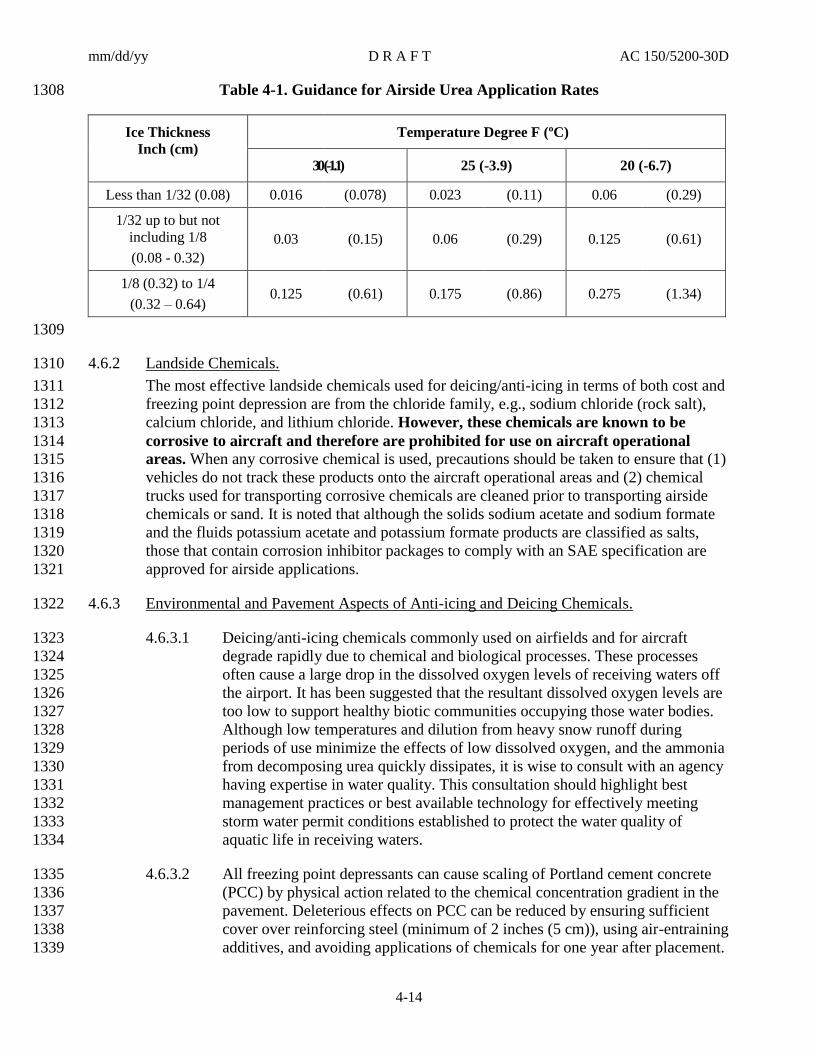
mm/dd/yy D R A F T AC 150/5200-30D
4-14
Table 4-1. Guidance for Airside Urea Application Rates 1308
Ice Thickness
Inch (cm)
Temperature Degree F (ºC)
30 (-1.1) 25 (-3.9) 20 (-6.7)
Less than 1/32 (0.08) 0.016 (0.078) 0.023 (0.11) 0.06 (0.29)
1/32 up to but not
including 1/8
(0.08 - 0.32)
0.03 (0.15) 0.06 (0.29) 0.125 (0.61)
1/8 (0.32) to 1/4
(0.32 – 0.64) 0.125 (0.61) 0.175 (0.86) 0.275 (1.34)
1309
Landside Chemicals. 4.6.21310
The most effective landside chemicals used for deicing/anti-icing in terms of both cost and 1311
freezing point depression are from the chloride family, e.g., sodium chloride (rock salt), 1312
calcium chloride, and lithium chloride. However, these chemicals are known to be 1313
corrosive to aircraft and therefore are prohibited for use on aircraft operational 1314 areas. When any corrosive chemical is used, precautions should be taken to ensure that (1) 1315
vehicles do not track these products onto the aircraft operational areas and (2) chemical 1316
trucks used for transporting corrosive chemicals are cleaned prior to transporting airside 1317
chemicals or sand. It is noted that although the solids sodium acetate and sodium formate 1318
and the fluids potassium acetate and potassium formate products are classified as salts, 1319
those that contain corrosion inhibitor packages to comply with an SAE specification are 1320
approved for airside applications. 1321
Environmental and Pavement Aspects of Anti-icing and Deicing Chemicals. 4.6.31322
Deicing/anti-icing chemicals commonly used on airfields and for aircraft 4.6.3.11323
degrade rapidly due to chemical and biological processes. These processes 1324
often cause a large drop in the dissolved oxygen levels of receiving waters off 1325
the airport. It has been suggested that the resultant dissolved oxygen levels are 1326
too low to support healthy biotic communities occupying those water bodies. 1327
Although low temperatures and dilution from heavy snow runoff during 1328
periods of use minimize the effects of low dissolved oxygen, and the ammonia 1329
from decomposing urea quickly dissipates, it is wise to consult with an agency 1330
having expertise in water quality. This consultation should highlight best 1331
management practices or best available technology for effectively meeting 1332
storm water permit conditions established to protect the water quality of 1333
aquatic life in receiving waters. 1334
All freezing point depressants can cause scaling of Portland cement concrete 4.6.3.21335
(PCC) by physical action related to the chemical concentration gradient in the 1336
pavement. Deleterious effects on PCC can be reduced by ensuring sufficient 1337
cover over reinforcing steel (minimum of 2 inches (5 cm)), using air-entraining 1338
additives, and avoiding applications of chemicals for one year after placement. 1339

mm/dd/yy D R A F T AC 150/5200-30D
4-15
Concrete meeting the compressive strength outlined in ASTM C 672, Scale 1340
Resistance of Concrete Surfaces Exposed to Deicing Chemicals, will perform 1341
well when subjected to chemical deicers. Certain PCC runways may 1342
experience excessive alkali-silica reaction that causes accelerated deterioration 1343
and cracking. Proper selection of aggregates and the use of additives can 1344
mitigate this occurrence in new PCC runways. Coatings for existing PCC 1345
runways are being researched to determine their effectiveness in mitigating this 1346
occurrence. No surface degradation of asphalt concrete has been observed from 1347
approved chemicals. 1348
Runway Friction Improvements. 4.71349
Since snow and ice degrade the coefficient of friction between rubber tires and pavement 1350
and could pose an unsafe condition for aircraft, it is important to clear down to bare 1351
pavement whenever possible. There are situations where complete removal is difficult or 1352
impossible to achieve within a required span of time. At temperatures approaching the 1353
eutectic temperature of an anti-icing/deicing chemical, it may require an hour or more for 1354
the dry chemical to go into solution and melt the ice. There are two techniques for 1355
modifying the frictional coefficient of a pavement covered with ice or compacted snow—1356
one by building in a texture on the surface and the other by a surface treatment of the ice or 1357
snow. It is emphasized that heated sand is not a deicing chemical and will not remove ice 1358
or compacted snow. In fact, heavy applications of heated sand can insulate the ice and 1359
therefore prolong its presence. 1360
Pavement Surface Modification. 4.7.11361
Surface texture and surface treatment modifications by themselves will not increase the 1362
coefficient of friction of ice formed on the surface, but both will enhance the response of 1363
chemical treatment. 1364
Pavement Grooving. 4.7.1.11365
Grooves cut into the pavement will trap anti-icing/deicing chemicals, reduce 1366
loss, and prolong their actions. Grooves also assist in draining melt water and 1367
preventing refreezing. There is empirical evidence that grooves and porous 1368
friction courses modify the thermal characteristics of a pavement surface, 1369
probably by reducing the radiant heat loss, and delay the formation of ice. 1370
There do not appear to be any negative effects from grooving pavements. 1371
Porous Friction Course (PFC). 4.7.1.21372
PFC has generally the same benefits as grooving. Open graded asphalt 1373
concrete is less effective in improving coefficient of friction under icing 1374
conditions because the open spaces will fill with compacted snow and, to a 1375
lesser extent, with ice in the case of freezing rain. Most maintenance personnel 1376
have found that chemical treatment rates may need to be increased on this type 1377
of pavement compared to dense graded asphalt concrete because of drainage of 1378
the chemical. The drainage characteristics also change as sand accumulates in 1379
the voids and plugs them. 1380

mm/dd/yy D R A F T AC 150/5200-30D
4-16
Surface Treatment. 4.7.21381
This is the approach taken to rapidly increase the frictional coefficient of an ice surface. 1382
Two methods are generally used by airport operators, namely applying coarse granular 1383
material (heated sand) or scarifying or breaking up the ice surface with a serrated blade. 1384
Sand. 4.7.2.11385
Granular material provides a roughened surface on ice and thereby improves 1386
airplane directional control and braking performance. Use of sand should be 1387
controlled carefully on turbojet movement areas to reduce engine erosion. If 1388
the granules do not embed or adhere to the ice, they will likely be ingested into 1389
engines and/or blown away by wind or scattered by traffic action and thus 1390
serve no useful function. This is particularly the case when unheated sand is 1391
applied to ice or compacted snow is at temperatures below about 20° F (-6.7° 1392
C) since no water film exists on the surface to act as an adhesive. There are 1393
three approaches to reducing loss of sand: (1) it can be heated to enhance 1394
embedding into the cold surface; (2) the granules can be coated with an 1395
approved deicing chemical in the stockpile or in the distributing truck hopper; 1396
or (3) diluted deicing chemical can be sprayed on the granules or the pavement 1397
at the time of spreading. If stockpiles are kept in a heated enclosure and spread 1398
promptly after truck loading, sufficient heat may remain for embedding 1399
without further treatment. Maintenance personnel should make a test on an 1400
unused pavement covered with ice or compacted snow to determine if bonding 1401
is adequate to prevent loss. When the slippery condition giving rise to the 1402
requirement for sand has passed, treated pavements should be swept as soon as 1403
air traffic volume allows to remove the residue to prevent engine damage. 1404
Other factors to consider when deciding to apply sand are pavement and air 1405
temperatures and frequency of operations. The use of other abrasives, such as 1406
slag, is not recommended since some metal-based slags may affect engine 1407
components. 1408
Note: Upon applying sand, airport operators must ensure the application is 1409
monitored for effectiveness and remains in place for the intended location of 1410
the surface treated. 1411
Ice Scarifying. 4.7.2.21412
Directional control of vehicles on an ice or compacted snow surface can be 1413
improved dramatically by cutting longitudinal grooves in the ice. However, no 1414
improvement in braking effectiveness results from grooving, so this approach 1415
should only be employed when very low temperatures prevent rapid chemical 1416
action or mechanical removal. The grooves trap sand or chemicals and hence 1417
contribute to improving the surface friction characteristics and melting action. 1418
Sand. 4.81419
Material. 4.8.11420
All sands do not perform the same. In general, the greater the quantity of sand applied, the 1421
greater the increase in traction. Fine sands show superior performance on warmer ice (>20° 1422

mm/dd/yy D R A F T AC 150/5200-30D
4-17
F (-7° C)), while coarser sands show superior performance on colder ice (<15° F (-9° C)). 1423
For the purpose of this AC, sand retained on a #30 sieve is considered “coarse”, and sand 1424
passing through a #30 sieve is considered “fine”. The FAA recommends that airport 1425
operators inform tenant airlines about the material used on the runways. 1426
Note: Slag material is not recommended because engine manufacturers have reported 1427
problems with internal engine components, especially for certain types of metal slags. 1428
Standard Gradation. 4.8.1.11429
Table 4-2 provides the standard gradation for sand. Materials applied to 1430
aircraft movement surfaces must consist of washed granular mineral sand 1431
particles free of stone, clay, debris, slag, chloride salts, and other corrosive 1432
substances. The pH of the water solution containing the material must be 1433
approximately neutral (pH 7). Material must meet the following gradation 1434
using a U.S.A. Standard Sieve conforming to ASTM E 11-81. The upper and 1435
lower sand gradations are in response to engine manufacturers input that finer 1436
sized sand from time to time produced hard snowballs while coarser sized sand 1437
damaged engine components. The latter case additionally causes damage to the 1438
fuselage. 1439
Table 4-2. Standard Gradation for Sand 1440
Sieve Designation Percent by Weight Passing
8 100
80 0-2
Optimum Gradation. 4.8.1.21441
Table 4-3 provides an expanded sand gradation standard for optimum 1442
performance on both warm and cold ice conditions by balancing fine and 1443
coarse particles. For this reason, the inclusion of the #30 sieve beyond that 1444
required by the FAA standard gradation of Table 4-2 is recommended. Airport 1445
operators may modify these recommended gradation requirements to suit their 1446
needs, as long as the gradation meets the requirements of Table 4-2. The use 1447
of sand that does not meet the gradation requirements of Table 4-2 must be 1448
coordinated with the FAA Safety and Standards Branch, development of a 1449
Modification of Standards coordinated, and airport users advised. 1450

mm/dd/yy D R A F T AC 150/5200-30D
4-18
Table 4-3. Expanded Sand Gradation Standard 1451
Sieve Designation Percent by Weight Passing
8 100
30 20-50
80 0-2
Application. 4.8.21452
Hard silica sand provides the greatest increase in traction and remains effective the longest 1453
when compared to softer materials because of its resistance to fracture. However, it is also 1454
very abrasive and, therefore, more potentially damaging to airplane engines. Limestone is 1455
softer and may be used where available if abrasion needs to be reduced. Tests have shown 1456
that application rates of 0.02 - 0.10 lb./ft2 (0.1 - 0.5 kg/m
2) of sand will substantially 1457
increase the runway friction coefficient. The greater quantity is required at temperatures 1458
approaching 32° F (0° C), the amount decreasing as the temperatures drops. Fractured 1459
particles provide some advantage in traction enhancement but not enough to justify much 1460
of a difference in cost. In terms of color, darker sands are preferred over light-colored 1461
sands to offer visual verification where sand has been applied. 1462
Chemically or Heat-treated Sand. 4.8.31463
The FAA recommends that sand be heated or treated with approved chemicals to make it 1464
adhere better to ice or compacted snow, thereby minimizing the possibility of airplane 1465
engine ingestion and preventing loss of material (see 14 CFR Section 139.313(b)(3).) At 1466
temperatures above 15° F (-9° C), a solution of airside urea may be used; below this 1467
temperature, other approved fluids will be more effective. Airport operators report that 1468
approximately 8 to 10 gallons (30-40 l) of fluid chemical are required to coat one ton of 1469
sand. The most effective method of applying the chemical is to spray it on granules as they 1470
drop onto the spinner mechanism of a material spreader since wetting is more thorough 1471
than pouring the chemicals onto the stockpile or the hopper load. Below 0° F (-18° C), 1472
heated sand can be more effective because of more rapid adhesion of the granules to ice. If 1473
sand will be heated, a coarser mixture (#30 sieve is considered “coarse”) should be used, as 1474
fine particles cool too rapidly on dispersal before hitting the ice. Sands heated to 80° F 1475
(27° C) or higher adhere well to ice. 1476

mm/dd/yy D R A F T AC 150/5200-30D
5-1
CHAPTER 5. SURFACE ASSESSMENT AND REPORTING 1477
Airport Operator Responsibility. 5.11478
The Airport Operator must be aware of all paved surface conditions in order to plan and 5.1.11479
carry out appropriate maintenance actions in accordance with the Snow and Ice Control 1480
plan. Equipped with this information, the airport operator will be able to better determine 1481
when to close a runway, taxiway, or apron area to aircraft use. Assessing and reporting 1482
the surface condition of a runway poses a particular challenge for an airport operator and is 1483
of the utmost importance to airport users. Pilot braking action reports are the source of 1484
braking action information most accepted by pilots. However, they can vary significantly, 1485
even when reporting on the same contaminated surface conditions. Furthermore, they only 1486
apply to the portion of the runway where braking occurred. Assessments based solely on 1487
the values generated by friction measuring equipment do not provide a consistent and 1488
usable correlation between friction measurements and airplane braking performance. The 1489
use of a truck or automobile to estimate airplane braking action is also subjective. 1490
Previous methods of determining runway slipperiness have been found to be inadequate 5.1.21491
and have either not prevented or have contributed to runway excursion incidents. A major 1492
contributing factor has been a contaminated (snow, ice, slush, water, etc.) runway being 1493
more slippery than pilots expected. This has been typically due to methods of estimating 1494
available runway friction levels not being timely, accurate, or able to be correlated to 1495
airplane stopping performance. As a result, runway excursions are the leading cause of 1496
accidents worldwide.. The severity of these accidents varies from minor damage to 1497
significant equipment loss and fatalities. In response to this recurring safety concern, the 1498
FAA, in partnership with industry stakeholders (aircraft operators, aircraft manufacturers, 1499
airport operators, international civil aviation authorities and professional aviation 1500
organizations) developed more comprehensive and standardized methods of assessing and 1501
reporting surface conditions. 1502
The airport operator in complying with 14 CFR Part 139.339, is required to utilize the 5.1.31503
NOTAM system as the primary method for collection and dissemination of airport 1504
information to air carriers, and other airport users. When disseminating airport condition 1505
information there are three methods available to airport operators. The first and preferred 1506
method is NOTAM Manager, a direct-entry system. The second alternative method is the 1507
ENII system. This system is similar to NOTAM Manager but lacks some of the direct 1508
entry functionality. The third method to issue a NOTAM is via telephone. This method is 1509
the least preferred due to the amount of time required to communicate airfield conditions to 1510
Flight Service, and the manual recording of notifications and disseminations in airport 1511
logs. When supplemental or secondary systems are used, the airport operator must ensure 1512
they are approved and consistent with Part 139. A record of the dissemination (issuance 1513
and cancellation) of NOTAM information must be retained by the airport operator. 1514

mm/dd/yy D R A F T AC 150/5200-30D
5-2
Conditions Acceptable to Use Decelerometers or Continuous Friction Measuring 5.1.41515
Equipment to Conduct Runway Friction Surveys on Frozen Contaminated Surfaces. 1516
The data obtained from such runway friction surveys are only considered to be 5.1.4.11517
reliable when the surface is contaminated under any of the following 1518
conditions: 1519
1. Ice or wet ice. Wet ice is a term used to define ice surfaces that are 1520
covered with a thin film of moisture caused by melting. The liquid water 1521
film depth of .04 inches (1 mm) or less, is insufficient to cause 1522
hydroplaning. 1523
2. Compacted snow at any depth. 1524
3. Dry snow 1 inch or less. 1525
4. Wet snow or slush 1/8 inch or less. 1526
It is not acceptable to use decelerometers or continuous friction measuring 5.1.4.21527
equipment to assess any contaminants outside of these parameters. 1528
Runway Friction Surveys. 5.21529
FAA-approved friction measuring equipment may be employed to help in determining the 1530
effects of friction-enhancing treatments, in that it can show the trend of a runway as to 1531
increasing or decreasing friction. Airport operators must not attempt to correlate friction 1532
readings (Mu numbers) to Good/Medium (Fair)/Poor or Nil runway surface conditions, as 1533
no consistent, usable correlation between Mu values and these terms has been shown to 1534
exist to the FAA’s satisfaction. It is important to note that while manufacturers of the 1535
approved friction measuring equipment may provide a table that correlates braking action 1536
to Mu values, these correlations are not supported by the FAA. To ensure that data 1537
collected are accurate, qualified personnel should use FAA-approved equipment and 1538
follow the manufacturer’s instructions for use. Further guidance on runway friction 1539
measurement may be found in AC 150/5320-12, Measurement, Construction, and 1540
Maintenance of Skid-Resistant Airport Pavement Surfaces. 1541
Note: It is no longer acceptable to report or disseminate friction (Mu) values via the 1542
NOTAM System. Friction (Mu) values have been replaced by Runway Condition Codes, 1543
which are included in the Runway Condition NOTAM. See Paragraph 5.3.3.1.2. 1544
When to Conduct Runway Friction Surveys on Contaminated Surfaces. 5.2.11545
The airport operator should conduct runway friction surveys whenever it is thought that the 1546
information will be helpful in the overall snow/ice removal effort, and the conditions are 1547
within the limits above. Within those conditions, runway friction assessments should be 1548
conducted: 1549
When the central portion of the runway, centered longitudinally along the runway 1.1550
centerline, is contaminated over a distance of 500 feet (152 m) or more. 1551
Following all snow clearing, anti-icing, deicing, or sanding operations. 2.1552

mm/dd/yy D R A F T AC 150/5200-30D
5-3
Immediately following any aircraft incident or accident on the runway, recognizing 3.1553
that responding ARFF or other circumstances may restrict an immediate response. 1554
Friction Measuring Procedures. 5.2.21555
Calibration. 5.2.2.11556
The friction measuring equipment operator is responsible for ensuring that 1557
equipment is correctly calibrated in accordance with its operations manual. 1558
Some devices perform an automatic electronic calibration each time the power 1559
is turned on; others require the operator to initiate the calibration procedure. In 1560
the latter case, the electronic calibration should be performed before placing 1561
the equipment in operation for the day. The equipment operator should also 1562
check all ancillary systems (such as recording devices, tow vehicles, and two-1563
way radios). Factory calibrations of a CFME should be performed as 1564
recommended by the manufacturer, or sooner if indicated by erroneous data. 1565
The operator responsible for the device should perform only adjustments 1566
recommended by the manufacturer. Factory calibration should be scheduled 1567
during the spring-summer season to ensure the equipment will be ready for the 1568
next winter’s runway friction surveys. 1569
Advance Coordination. 5.2.2.21570
Runway friction surveys take time, and while the tests are being conducted, the 1571
runway may be closed to airplane operations. Airport operators should work 1572
closely with ATC, the airlines, and/or the fixed-base operators to minimize 1573
interruption to airplane operations. Close coordination, communication, and 1574
cooperation among all parties concerned are vital to ensure personnel safety, 1575
efficient traffic management, and timely runway friction surveys. The airport 1576
operator should request from ATC an appropriate period of time to conduct a 1577
friction survey of the runway. At a high-activity airport, runway friction 1578
surveys may have to be conducted in segments. The airport operator should 1579
request ATC to plan a break in arrival and departure traffic to provide time to 1580
conduct a runway friction survey. With such planning, the friction survey team 1581
can position itself adjacent to the runway when ATC gives the clearance to 1582
proceed. This cooperative effort with ATC will result in minimal disruptions to 1583
airplane operations. 1584
Air Traffic Control Clearance When Conducting Runway Friction 5.2.2.31585
Surveys on Open Runways. 1586
Before proceeding with the friction survey at controlled airports, the airport 1587
operator responsible for conducting the friction survey must contact ATC for 1588
runway clearance according to standard procedures and remain in radio contact 1589
during the entire time it takes to complete the friction survey on an open 1590
runway. ATC will provide appropriate clearances on and off the runway to 1591
permit the airport operator access to conduct the friction survey. At 1592
uncontrolled airports, airport operations personnel must be alert for aircraft and 1593
advise any air traffic on advisory frequencies before, during, and after 1594
completion of the runway friction survey. In this situation, coordination among 1595

mm/dd/yy D R A F T AC 150/5200-30D
5-4
the area ATC, the airport operator, and the airplane operators is particularly 1596
important to ensure that safe and efficient airplane operations are maintained at 1597
all times. 1598
Location and Direction to Conduct Runway Friction Surveys. 5.2.2.41599
5.2.2.4.1 Lateral Location. 1600
On runways that serve primarily narrow-body airplanes, runway friction 1601
surveys should be conducted approximately 10 feet (3 m) from the runway 1602
centerline. On runways that serve primarily wide-body airplanes, runway 1603
friction surveys should be conducted approximately 20 feet (6 m) from the 1604
runway centerline. Unless surface conditions are noticeably different on the 1605
two sides of the runway centerline, only one survey is needed, and it may be 1606
conducted on either side. 1607
5.2.2.4.2 Direction. 1608
Friction measuring equipment is operated in the same direction that airplanes 1609
are landing. 1610
5.2.2.4.3 Runway Survey Zones. 1611
The runway length is divided into three equal zones: the touchdown, midpoint, 1612
and rollout zones. These zones are defined according to airplane landing 1613
direction. If possible, the entire survey should be completed in one pass. 1614
However, if ATC cannot schedule enough time to do a complete runway 1615
friction survey, the airport operator should request ATC to schedule each zone 1616
separately until all three zones have been completed. 1617
Conducting Runway Friction Surveys Using Decelerometers. 5.2.2.51618
A minimum of three braking tests are required in each zone to determine the 1619
average friction value for that zone. This will result in a minimum of nine tests 1620
for a complete runway friction survey. The vehicle speed for conducting the 1621
friction survey should be 20 mph (32 km/h). 1622

mm/dd/yy D R A F T AC 150/5200-30D
5-5
Table 5-1. Friction Survey Example 1623
Runway Zone 1
Touchdown
A qualified airport operator obtains four Mu readings in the
touchdown zone: 25, 27, 26, and 31. The average of these
readings is 27.25, which would be rounded to 27.
Runway Zone 2
Midpoint
Four readings are obtained for the midpoint zone: 26, 28, 28,
and 32. The average of 28.5, which would be rounded to 29.
Runway Zone 3
Rollout
After the minimum three readings (29, 30, and 31) are
obtained for the rollout zone, ATC instructs the operator to
clear the runway. It is not required that an equal number of
readings be obtained for each zone, so the three readings are
averaged to a reading of 30.
Conducting Runway Friction Surveys Using CFME. 5.2.2.61624
A runway friction survey is recommended for the full length of the runway to 1625
determine the average friction value for each zone. The survey may be 1626
conducted at any speed up to 40 mph (65 km/h) as safety considerations allow. 1627
Some CFME should be operated at slower speeds due to handling 1628
characteristics that are a function of their weight, measuring method, etc. 1629
Operators should be trained in the use of CMFE, and such training should 1630
include information on handling characteristics and optimum testing speeds. 1631
Recording Runway Friction Survey Data. 5.2.2.71632
The equipment operator should record all data and observations obtained from 1633
runway friction surveys. Recorded data and observations can be used to assess 1634
the effectiveness of runway surface treatments and snow removal operations 1635
and can aid in accident or incident investigations. Current friction 1636
measurement technologies are not reliable in determining braking effectiveness 1637
of a contaminated surface condition above measurements of 40. 1638
Runway Condition Assessments. 5.31639
Runway Condition Assessment Matrix (RCAM). 5.3.11640
The RCAM is the method by which an airport operator will report a runway surface 1641
assessment when contaminants are present. Once an assessment has been performed, the 1642
RCAM defines the format for which the airport operator will report and receive a runway 1643
conditions “Code” via the NOTAM System. The reported information allows a pilot to 1644
interpret the runway conditions in terms that relate to airplane performance. This approach 1645
is a less subjective means of assessing runway conditions by using defined objective 1646
criteria. Aircraft manufacturers have determined that variances in contaminant type, depth 1647
and air temperature can cause specific changes in aircraft braking performance. At the 1648
core of the RCAM is its ability to differentiate among the performance characteristics of 1649
given contaminants. 1650

mm/dd/yy D R A F T AC 150/5200-30D
5-6
Table 5-2. Runway Condition Assessment Matrix (RCAM) (for 1651
Airport Operators’ Use Only) 1652
Assessment Criteria Downgrade Assessment Criteria
Runway Condition Description Code Mu (μ) 1 Vehicle Deceleration or
Directional Control Observation
Pilot Reported Braking Action
Dry
6
--- ---
Frost
Wet (Includes damp and 1/8 inch depth or less of water) 1/8 inch (3mm) depth or less of:
Slush
Dry Snow
Wet Snow
5
Braking deceleration is normal for the wheel
braking effort applied AND directional control is
normal.
Good
-15ºC and Colder outside air temperature:
Compacted Snow
4
Braking deceleration OR directional control is between Good and
Medium.
Good to
Medium
Slippery When Wet (wet runway)
Dry Snow or Wet Snow (Any depth) over Compacted Snow
Greater than 1/8 inch (3mm) depth of:
Dry Snow
Wet Snow
Warmer than -15ºC outside air temperature:
Compacted Snow
3
Braking deceleration is noticeably reduced for the
wheel braking effort applied OR directional control is
noticeably reduced.
Medium
Greater than 1/8 (3mm) inch depth of:
Water
Slush 2 Braking deceleration OR
directional control is between Medium and Poor.
Medium to
Poor
Ice 2
1
Braking deceleration is significantly reduced for the wheel braking effort applied
OR directional control is significantly reduced.
Poor
Wet Ice 2
Slush over Ice
Water over Compacted Snow 2
Dry Snow or Wet Snow over Ice 2
0
Braking deceleration is minimal to non-existent for
the wheel braking effort applied OR directional
control is uncertain.
Nil
1653
1 The correlation of the Mu (µ) values with runway conditions and condition codes in the Matrix are only approximate ranges for a 1654 generic friction measuring device and are intended to be used only to downgrade a runway condition code. Airport operators 1655 should use their best judgment when using friction measuring devices for downgrade assessments, including their experience with 1656 the specific measuring devices used. 1657
2 In some circumstances, these runway surface conditions may not be as slippery as the runway condition code assigned by the 1658 Matrix. The airport operator may issue a higher runway condition code (but no higher than code 3) for each third of the runway if 1659
40 o
r Hig
he
r
39 to
30
29 to
21
20 o
r Lo
wer

mm/dd/yy D R A F T AC 150/5200-30D
5-7
the Mu value for that third of the runway is 40 or greater obtained by a properly operated and calibrated friction measuring device, 1660 and all other observations, judgment, and vehicle braking action support the higher runway condition code. The decision 1661 to issue a higher runway condition code than would be called for by the Matrix cannot be based on Mu values alone; all 1662 available means of assessing runway slipperiness must be used and must support the higher runway condition code. This 1663 ability to raise the reported runway condition code to a code 1, 2, or 3 can only be applied to those runway conditions listed under 1664 codes 0 and 1 in the Matrix. 1665
The airport operator must also continually monitor the runway surface as long as the higher code is in effect to ensure that the 1666 runway surface condition does not deteriorate below the assigned code. The extent of monitoring must consider all variables that 1667 may affect the runway surface condition, including any precipitation conditions, changing temperatures, effects of wind, frequency 1668 of runway use, and type of aircraft using the runway. If sand or other approved runway treatments are used to satisfy the 1669 requirements for issuing this higher runway condition code, the continued monitoring program must confirm continued 1670 effectiveness of the treatment. 1671
Caution: Temperatures near and above freezing (e.g., at -3°C and warmer) may cause contaminants to behave 1672 more slippery than indicated by the runway condition code given in the Matrix. At these temperatures, airport 1673 operators should exercise a heightened level of runway assessment, and should downgrade the runway condition 1674 code if appropriate. 1675

mm/dd/yy D R A F T AC 150/5200-30D
5-8
Overview of the Basic RCAM Process.5.3.21676
End of Process
Step 1: RCAM applicability
Content of SICP plan
Understanding RCAM usage
Percentage of runway contaminated
Is greater than
25% of overall
runway surface
contaminated?
Report ONLY contaminant percentage,
type and depth for each runway third,
and any treatment via FICON NOTAM.
RCAM Runway Condition Code must not
be assigned or reported.
Step 3: Validating Runway
Condition Codes
Assigned Code compared
to experienced
slipperiness.
Determine need to
downgrade based on
other observations.
Apply all of the following available criteria:
Airport operator to use available friction
devices, experience and observations.
Vehicle deceleration or directional control.
Both are a concern and do not have to be
simultaneous.
Pilot reported braking action will rarely
apply to the full length of the runway.
Determine the contaminants
present for each third, and
assign Runway Condition Code.
Is Runway
Condition Code
downgrade
action required?
Step 2: Apply
assessment criteria
Contaminant type &
depth
Temperature
considerations
Corresponding Runway
Condition Code
Code identified for each
runway third
Code identified by
reviewing all Runway
Condition Description
categories
Report contaminants
and Runway
Condition Codes via
FICON NOTAM.
NOTE: Runway
Condition Code triggers
aircraft operators to
conduct takeoff and
landing performance
assessment.
YES
NO
YES
NO
1677

mm/dd/yy D R A F T AC 150/5200-30D
5-9
RCAM Components. 5.3.31678
Assessment Criteria. 5.3.3.11679
This section of the RCAM consists of a Runway Condition Description and a 1680
Runway Condition Code. This section includes contaminant type and depth 1681
categories which are objective assessments that have been determined by 1682
airplane manufacturers to cause specific changes in the airplane braking 1683
performance. These contaminants correspond to a reportable ‘shorthand’ 1684
Runway Condition Code when applicable. 1685
5.3.3.1.1 Runway Condition Description. 1686
The Runway Condition Description column of the RCAM provides 1687
contaminants that are directly correlated to airplane takeoff and landing 1688
performance. The description sections, ranging in terms of slipperiness, are 1689
categorized based on type and depth of contaminant and temperature. 1690
Figure 5-1. Runway Condition Description Column of the RCAM 1691
1692

mm/dd/yy D R A F T AC 150/5200-30D
5-10
5.3.3.1.2 Code (Runway Condition Code – RwyCC). 1693
Runway Condition Codes (Format: X/X/X) represent the runway condition 1694
description based on defined terms and increments. Use of these codes 1695
harmonizes with ICAO Annex 14, providing a standardized “shorthand” 1696
format for reporting RwyCC (which replaces Mu values), and are used by 1697
pilots to determine landing performance parameters when applicable. Runway 1698
Condition Codes are disseminated via the following methods: 1699
1. Federal NOTAM System, preferably through NOTAM Manager or 1700
equivalent system(s); 1701
2. Airport Traffic Control Tower (ATCT) (as applicable); 1702
3. Flight Service Station (FSS) (as applicable); and 1703
4. Directly from airport operator via Common Traffic Advisory Frequency 1704
(as applicable). 1705
Figure 5-2. Runway Condition Code (RwyCC) Column of the RCAM 1706
1707

mm/dd/yy D R A F T AC 150/5200-30D
5-11
Downgrade Assessment Criteria. 5.3.3.21708
When data from the shaded area in the RCAM (i.e., CFME/deceleration 1709
devices, pilot reports, or observations) suggest conditions are worse than 1710
indicated by the present contaminant, the airport operator should exercise good 1711
judgment and, if warranted, report lower runway condition codes than the 1712
contamination type and depth would indicate in the RCAM below. While pilot 1713
reports (PIREPs) of braking action provide valuable information, these reports 1714
rarely apply to the full length of the runway as such evaluations are limited to 1715
the specific sections of the runway surface in which in which wheel braking 1716
was utilized. Downgrade assessment criteria may never be used to upgrade 1717
contaminant-based assessments of condition codes (e.g., from 2 to 3). 1718
5.3.3.2.1 Mu (µ) (Friction Assessment). 1719
The correlation of the Mu (µ) values with runway conditions and condition 1720
codes in the RCAM are only approximate ranges for a generic friction 1721
measuring device and are intended to be used only to downgrade a runway 1722
condition code. Airport operators should use their best judgment when using 1723
friction measuring devices for downgrade assessments, including their 1724
experience with the specific measuring devices used. 1725

mm/dd/yy D R A F T AC 150/5200-30D
5-12
Figure 5-3. Friction Assessment Column of the RCAM 1726
1727
5.3.3.2.2 Vehicle Deceleration or Directional Control Observation. 1728
This column is used to correlate estimated vehicle braking experienced on a 1729
given contaminant. 1730

mm/dd/yy D R A F T AC 150/5200-30D
5-13
Figure 5-4. Vehicle Deceleration or Directional Control Observation Column of the RCAM 1731
1732
5.3.3.2.3 Pilot Reported Braking Action. 1733
This is a report of braking action on the runway, by a pilot, providing other 1734
pilots with a degree/quality of expected braking. The braking action 1735
experienced is dependent on the type of aircraft, aircraft weight, touchdown 1736
point, and other factors. 1737
1. Good: More braking capability is available than is used in typical 1738
deceleration on a non-limiting runway (i.e., a runway with additional 1739
stopping distance available). Directional control good. 1740
2. Medium (Fair): Noticeably degraded braking condition. Expect and plan 1741
for a longer stopping distance such as might be expected on a packed or 1742
compacted snow-covered runway. Effective directional control. 1743
3. Poor: Very degraded braking condition (a potential for hydroplaning). 1744
Expect and plan for a significantly longer stopping distance such as might 1745

mm/dd/yy D R A F T AC 150/5200-30D
5-14
be expected on an ice covered runway. Directional control minimally 1746
effective. 1747
4. Nil: Braking action is minimal to non-existent and/or directional control 1748
uncertain. 1749
Figure 5-5. Pilot Reported Breaking Action Column of the RCAM 1750
1751
Applying the RCAM to a Runway Assessment. 5.41752
To use the RCAM, the airport operator will use the same runway condition assessment 1753
practices as they have used in the past. The airport operator will assess surfaces, report 1754
contaminants present, and obtain Runway Condition Codes (RwyCC) based on the RCAM 1755
when applicable. The RwyCCs may vary for each third of the runway if different 1756
contaminants are present. However, the same RwyCC may be applied when a uniform 1757
coverage of contaminants exists. 1758

mm/dd/yy D R A F T AC 150/5200-30D
5-15
Note: A RwyCC of ‘0’ must never be reported, as this is an unsafe condition. The 1759
runway must be closed, and not reopened until the unsafe condition no longer exists. 1760
Step 1: RCAM Applicability. 5.4.11761
Operating with an understanding of the RCAM, the airport operator must first determine 1762
whether the overall runway length and width is contaminated greater than 25 percent. 1763
If 25 percent or less of the overall runway length and width is covered with 5.4.1.11764
contaminants, RwyCCs must not be applied, or reported. The airport operator 1765
in this case, will simply report the contaminant percentage, type and depth for 1766
each third of the runway, to include any associated treatments or 1767
improvements. 1768
Or 1769
If the overall runway coverage is greater than 25 percent, RwyCCs must be 1770
assigned, and reported, informing airplane operators of the contaminant 1771
present, and associated codes for each third of the runway. (The reported 1772
codes, will serve as a trigger for all airplane operators to conduct a takeoff 1773
and/or landing performance assessment). 1774
Step 2: Apply Assessment Criteria 5.4.21775
Based on the contaminants observed, the airport operators must reference the RCAM, and 1776
assign the relevant Runway Condition Code for each third of the runway. (Note: The 1777
following contaminants are listed in more than one category: Dry Snow, Wet Snow, Slush, 1778
and Water, which are assigned Codes based on depth; Compacted Snow, is coded based on 1779
the outside air temperature). 1780
Note: RwyCCs will be automatically generated for users connected to the NOTAM 1781
Manager system. The airport operator would only need to input the contaminant type and 1782
depth for each runway third. 1783
Step 3: Validating RwyCCs. 5.4.31784
With the contaminant assessment and code assignment completed, the airport operator may 1785
determine that the RwyCCs accurately reflect the runway condition. If so, no further 1786
assessment action is necessary, and the RwyCCs generated may be disseminated. 1787
However, the airport operator may determine a need exists to downgrade the RwyCC 1788
(assessment is indicating a more slippery condition than is generated by the RCAM) 1789
because of other observations related to runway slipperiness. When necessary, use of the 1790
RCAM Downgrade Assessment Criteria (grey columns) may assist in making this 1791
determination. 1792
Note: The criteria in the grey columns of the RCAM may only be used to downgrade the 1793
RwyCCs. 1794
Step 3A: Mu (µ). 5.4.3.11795
When conditions are acceptable for the airport operator to use available friction 1796
devices, the airport operator may utilize Mu readings as a means to assess 1797

mm/dd/yy D R A F T AC 150/5200-30D
5-16
runway slipperiness for downgrading, or to validate the RwyCCs generated by 1798
the RCAM. 1799
Step 3B: Vehicle Control. 5.4.3.21800
Vehicle deceleration or directional control may cause concerns for the airport 1801
operator. These concerns could be for either deceleration or directional control 1802
issues. However, they need not occur simultaneously for concern to exist. 1803
Step 3C: Pilot Reported Braking Action. 5.4.3.31804
Pilot reports, which provide valuable information, rarely apply to the full 1805
length of the runway. As such, these reports are limited to the specific sections 1806
of the runway surface in which wheel braking was applied. 1807
Note: Temperatures near and above freezing (e.g., at negative -3C and warmer) may cause 1808
contaminants to behave more slippery that indicated by the runway condition code given in 1809
the RCAM. At these temperatures, airport operators should exercise a heightened 1810
awareness of airfield conditions, and should downgrade the RwyCC if appropriate. 1811
Upgrade Criteria Based on Friction Assessments. 5.51812
Generally, it is not recommended that airport personnel upgrade runway condition codes 5.5.11813
from what is defined in the RCAM. Given the friction variability of certain contaminants, 1814
there are circumstances when a RwyCC of ‘0’ or ‘1’ (Ice, Wet Ice, Slush over Ice, Water 1815
over Compacted Snow, or Dry or Wet Snow over Ice) may not be as slippery as the 1816
RwyCC generated by the RCAM. In these very specific circumstances, the airport operator 1817
may upgrade the RwyCC up to but no higher than a RwyCC of ‘3’, only when all of the 1818
following requirements are met: 1819
All observations, judgment, and vehicle braking action support the higher RwyCC, and 1.1820
Mu values greater than 40 are obtained for the affected third(s) of the runway by a 2.1821
calibrated friction measuring device that is operated within allowable parameters. 1822
This ability to raise the reported runway condition code to no higher than a code 3 can 3.1823
only be applied to those runway conditions listed under code 0 and 1 in the RCAM. 1824
(See footnote 2 on the RCAM.) 1825
The airport operator must also continually monitor the runway surface as long as the 4.1826
higher code is in effect to ensure that the runway surface condition does not deteriorate 1827
below the assigned code. 1828
a. The extent of monitoring must consider all variables that may affect the runway 1829
surface condition, including any precipitation conditions, changing temperatures, 1830
effects of wind, frequency of runway use, and type of aircraft using the runway. 1831
b. If sand or other approved runway 'treatments are used to satisfy the requirements 1832
for issuing the higher runway condition code, the monitoring program must 1833
confirm continued effectiveness of the treatment. 1834
mm/dd/yy D R A F T AC 150/5200-30D
5-17
‘Slippery When Wet’ Runway. 5.5.21835
For runways where a friction survey (conducted for pavement maintenance) failed to meet 1836
the minimum friction level classification specified in Advisory Circular 150/5320-12, the 1837
airport operator must report a RwyCC of ‘3’ for each affected third of the runway when 1838
wet. The runway condition description, ‘Slippery When Wet’ is used for this condition. 1839
Dry Runway. 5.5.31840
Use the term “DRY” to describe a surface that is neither wet nor contaminated. A FICON 1841
NOTAM must not be originated for the sole purpose of reporting a dry runway. A dry 1842
surface must be reported only when there is need to report conditions on the remainder of 1843
the surface. 1844
Reportable Contaminants without Performance Data. 5.61845
Contaminants such as ash, mud, oil, and sand are treated differently in term of reporting 1846
contaminants. For ash and mud, a measured depth must be reported when these 1847
contaminants are present. Oil, sand, and rubber contaminants are reported without a 1848
measured depth. These contaminants do not generate a RwyCC. See AC 150/5200-28 and 1849
JO 7930.2 for specific NOTAM examples. 1850
Condition Reporting. 5.71851
Personnel responsible for implementing the SICP must carefully monitor changing airfield 1852
conditions and disseminate information about those conditions in a timely manner to 1853
airport users. Part 139.339, requires airport operators to provide for the collection and 1854
dissemination of accurate airport condition information (movement areas and parking 1855
areas, and aprons/ramps) to all airport users when any pavement condition that is worse 1856
than bare and dry. Additionally, any condition that may affect the safe operations of 1857
aircraft, must be reported to all users. Critical information to airplane operators for the 1858
purpose of takeoff and landing performance includes the contaminant type, depth and 1859
associated RwyCCs when applicable. The determination of dry versus wet snow or slush 1860
is another key element in the report because of its potential for significant impact on 1861
airplane performance. 1862
Note: A significant change to condition reporting includes the requirement and ability to 1863
report ‘Wet’ when visible dampness, or water that is 1/8-inch or less in depth exists on any 1864
surface (runways, taxiways, aprons, holding bays). This change is largely due to the 1865
airplane performance differences that exist between wet, dry or runways with water greater 1866
than 1/8-inch in depth. 1867
Air Carriers and Other Airport Users. 5.7.11868
FICON and RwyCCs are also furnished to airlines, cargo and other airport operators fixed-1869
base operator, and others operating at the airport. FICON and RwyCCs should be 1870
broadcast on the Unicom, Common Traffic Advisory Frequency, or Airport Advisory 1871
Service Frequency. 1872

mm/dd/yy D R A F T AC 150/5200-30D
5-18
Information Exchanged Between the Airport and Pilots. 5.81873
The goal in reporting surface conditions is to provide pilots with the best information 5.8.11874
available to ensure safe operations. The RCAM is now the most objective method for 1875
performing condition assessments by airport operators. This validated method replaces 1876
subjective judgments with objective assessments that are tied directly to contaminant type 1877
and depth categories. These categories have been determined by airplane manufacturers to 1878
cause specific changes in airplane braking performance. 1879
Pilots and airplane operators are expected to use all available information, which should 5.8.21880
include runway condition reports as well as any available pilot braking action reports, to 1881
assess whether operations can be safely conducted. Although the FAA no longer permits 1882
airport operators to provide vehicle braking action or friction measurements to pilots, 1883
airport operators are permitted to use vehicle braking and friction values for assessing and 1884
tracking the trend of changing runway conditions. 1885
How to Report Runway Conditions. 5.8.2.11886
Whenever a runway is contaminated by ice, snow, slush, or water, the airport 1887
operator is responsible for providing current runway surface condition reports. 1888
Report runway surface conditions in terms of contaminant types and depths 1889
(except do not report depths for compacted snow and ice, and for standing 1890
water or slush depths less than 1/8 inch). When the cleared runway width is 1891
less than the full runway width, also report the conditions on the un-cleared 1892
width (runway edges) if different from the cleared width. When the RCAM is 1893
properly utilized, specific runway condition codes will be generated for 1894
contaminants present based on the identified contaminant list in AC 150/5200-1895
28 and JO 7930.2. 1896
When to Issue New Runway Condition Reports. 5.8.2.21897
Runway condition reports must be updated any time a change to the runway 1898
surface condition occurs. Changes that initiate updated reports include weather 1899
events, the application of chemicals or sand, or plowing or sweeping 1900
operations. Airport operators should not allow airplane operations on runways 1901
after such activities until a new runway condition report is issued reflecting the 1902
current surface condition(s) of affected runways. At certificated airports, such 1903
changes to the runway surface condition must be updated and appropriately 1904
disseminated so airplane operators are aware of the current conditions before 1905
continuing with their operations. During active snow events or rapidly 1906
changing conditions (e.g., increasing snowfall, rapidly rising or falling 1907
temperatures) airport operators are required to maintain a vigilant runway 1908
inspection process to ensure accurate runway condition reports. While pilot 1909
braking action reports provide valuable information, these reports may not 1910
apply to the full length of the runway as such evaluations are limited to the 1911
specific sections of the runway surface in which the airplane wheel braking 1912
was used. In addition, runway condition reports should be updated at least at 1913
the beginning of each shift of operations personnel. 1914
mm/dd/yy D R A F T AC 150/5200-30D
5-19
Requirements for Runway, Taxiway, and Apron and Holding Bay Closures. 5.91915
The previously accepted philosophy of the aviation industry was that the airport operator 5.9.11916
was obligated to provide an accurate description of the surface conditions, and it was 1917
solely up to the pilot to decide if a surface was safe for use. Accident data do not support 1918
such a philosophy, and FAA Flight Standards Service has determined that operations on 1919
surfaces reported as having NIL braking are inherently unsafe. Admittedly, this is a 1920
conservative approach considering the variation in pilot braking action reporting. 1921
Therefore, in lieu of the consequences of ignoring a NIL braking action report, 1922
requirements for closure of airport surfaces have been adopted. 1923
Note: To clarify, it is not acceptable for an airport to report a NIL braking action 1924
condition. NIL conditions on any surface require the closure of that surface. These 1925
surfaces may not be opened until the airport operator is satisfied that the NIL condition no 1926
longer exists. 1927
The following circumstances require the prescribed action by the airport operator: 5.9.21928
Runways. 5.9.2.11929
A NIL pilot braking action report (PIREP), or NIL braking action assessment 5.9.2.21930
by the airport operator, requires that the runway be closed before the next 1931
flight operation. The runway must remain closed until the airport operator is 1932
satisfied that the NIL condition no longer exists. 1933
5.9.2.2.1 When previous PIREPs have indicated GOOD or MEDIUM (FAIR) braking 1934
action, two consecutive POOR PIREPS should be taken as evidence that 1935
surface conditions may be deteriorating and require the airport operator to 1936
conduct a runway assessment. If the airport operator has not already instituted 1937
its continuous monitoring procedures (see Paragraph 5.11), this assessment 1938
must occur before the next operation. If the airport operator is already 1939
continuously monitoring runway conditions, this assessment must occur as 1940
soon as air traffic volume allows, in accordance with their SICP. 1941
Taxiways, Aprons and Holding Bays. 5.9.2.31942
1943
A NIL pilot braking action report (PIREP), or NIL braking action assessment 1944
by the airport operator, requires that a surface, including taxiways and aprons 1945
be closed before the next flight operation. The surface must remain closed until 1946
the airport operator is satisfied that the NIL condition no longer exists. 1947
Deteriorating Conditions. 5.9.2.41948
Include but are not limited to: 1949
1. Frozen or freezing precipitation. 1950
2. Falling air or pavement temperatures that may cause a wet runway to 1951
freeze. 1952

mm/dd/yy D R A F T AC 150/5200-30D
5-20
3. Rising air or pavement temperatures that may cause frozen contaminants 1953
to melt. 1954
4. Removal of abrasives previously applied to the runway due to wind or 1955
airplane affects. 1956
5. Frozen contaminants blown onto the runway by wind. 1957
Letter of Agreement (LOA) Between Airport Operator and Air Traffic Control 5.101958
Tower. 1959
To ensure that the airport operator receives needed information, Letters of Agreement 5.10.11960
(LOA) should be formalized between the airport operator and the air traffic control tower 1961
to identify the procedures and responsibilities for coordination and the reporting of runway 1962
surfaces conditions. LOA(s) should also specify how all pilot braking action reports 1963
(PIREPS) of “POOR” and “NIL” are to be immediately transmitted to the airport operator 1964
for action, as required by FAA Order 7110.65, Air Traffic Control. It should also include 1965
agreement on actions by Air Traffic personnel for immediate cessation of operations upon 1966
receipt of a “NIL” PIREP. 1967
Conversely, to ensure the ATCT receives necessary information from the airport operator, 5.10.21968
any letter of agreement should include procedures for how FICON and RwyCCs are 1969
transmitted. In the absence of an ATCT at the airport, the report should be supplied to the 1970
ATC facility that provides approach control service or to an appropriate flight service 1971
station (FSS). 1972
A reference to the signed LOA should be contained in the airport’s SICP. 5.10.31973
Continuous Monitoring. 5.111974
Under the conditions noted above, the airport operator must take all reasonable steps using 5.11.11975
all available equipment and materials that are appropriate for the condition to improve the 1976
braking action. If the runway cannot be improved, the airport operator must continuously 1977
monitor the runway to ensure braking action does not become NIL. The airport operator’s 1978
procedure for monitoring the runway should be detailed in the SICP. 1979
“Continuous monitoring” procedures can vary from airport to airport. Acceptable 5.11.21980
procedures may include: 1981
Observing which exit taxiways are being used. 1.1982
Maintaining a regular program of friction testing to identify trends in runway traction. 2.1983
Monitoring pavement physical conditions including air and surface temperatures, 3.1984
contaminant types and depths. 1985
Monitoring air traffic and pilot communications. 4.1986
Monitoring weather patterns. 5.1987
Increased self-inspection intervals. 6.1988

mm/dd/yy D R A F T AC 150/5200-30D
5-21
Airport Records and Log Controls. 5.121989
The SICP should include procedures to keep and maintain a log of NOTAMs that the 1990
airport operator issues. Reviewing NOTAM status should be a checklist item anytime the 1991
runway condition changes from that previously contained in the NOTAM and at the 1992
change of each shift of airport operations personnel. Also, retain a copy of the NOTAM as 1993
submitted and as transmitted for future reference and to demonstrate regulatory compliance 1994
when applicable. The Sample Airport Condition Assessment Worksheet located at 1995
Appendix A is provided for the airport operator to utilize as a form of record for assessing 1996
and reporting RwyCCs and estimated braking actions for other airport surfaces that would 1997
typically coincide with NOTAM issuance. 1998
Using “Conditions Not Monitored” NOTAMs. 5.131999
Airport operators should use “conditions-not-monitored” NOTAMs as a way to provide 2000
information to pilots related to the conditions not being monitored at the airport, perhaps 2001
due to operations hours or staffing. This standard has existed for airport operators to use 2002
over the years and provides the following guidance: “For airports, particularly smaller 2003
airports, that do not monitor weather conditions between certain hours due to staffing 2004
limitations, the issued NOTAM should contain text indicating that “airfield surface 2005
conditions are not monitored between the hours of ‘X – ‘Y.” This additional text helps to 2006
avoid erroneous condition assessments by users of the information.” Airport operators 2007
should avoid using “airport unattended” NOTAMs as a substitute for “conditions-not-2008
monitored” because this type of NOTAM sends the wrong message that other services 2009
provided by the airport, e.g. ATC, ARFF, fuel; are not available or accessible when the 2010
conditions are not being monitored perhaps due to operations hours or staffing. 2011
“Conditions-not-monitored” NOTAM is the preferred airport condition reporting for 2012
airport operators to use to address all airport surfaces or any individual surface as required. 2013
The period of applicability should be for both short and long term use. When airport 2014
operators use “conditions-not-monitored”, there may be times when the NOTAM will be 2015
issued when no recent observation will exist or it will not be tied to any recent Pilot Report 2016
NOTAM. This may differ slightly from what is currently illustrated in Order 7930.2 where 2017
it cites: “When the field conditions will not be monitored, follow the most recent 2018
observation with the words “‘CONDITIONS NOT MONITORED (date/time) 2019
(date/time).’” The time parameters specified must fall within the effective/expiration times. 2020
Airport operators may issue the “conditions-not-monitored NOTAM accompanied with the 2021
most recent observation and without any recent observation or Pilot Report. Either 2022
issuance will be acceptable as a NOTAM. 2023
Winter NOTAM Abbreviations. 5.142024
Snow-related NOTAMs should adhere to the format and abbreviations found in AC 2025
150/5200-28, Notices to Airmen (NOTAMs) for Airport Operators, and FAA Orders 2026
7930.2, Notices to Airmen (NOTAMs), and 7340.1, Contractions. 2027

mm/dd/yy D R A F T AC 150/5200-30D
5-22
This page intentionally left blank.2028
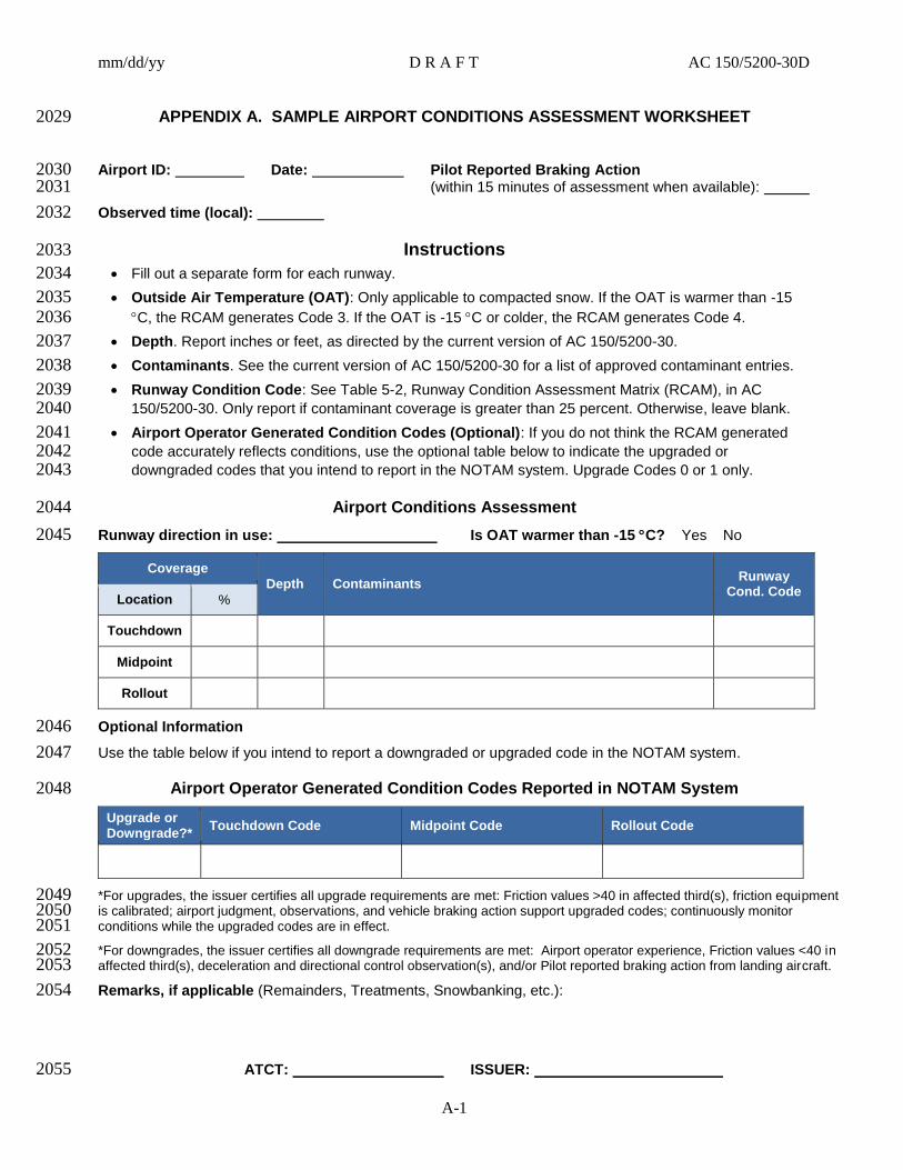
mm/dd/yy D R A F T AC 150/5200-30D
A-1
APPENDIX A. SAMPLE AIRPORT CONDITIONS ASSESSMENT WORKSHEET 2029
Airport ID: Date: Pilot Reported Braking Action 2030 (within 15 minutes of assessment when available): 2031
Observed time (local): 2032
Instructions 2033
Fill out a separate form for each runway. 2034
Outside Air Temperature (OAT): Only applicable to compacted snow. If the OAT is warmer than -15 2035 C, the RCAM generates Code 3. If the OAT is -15 C or colder, the RCAM generates Code 4. 2036
Depth. Report inches or feet, as directed by the current version of AC 150/5200-30. 2037
Contaminants. See the current version of AC 150/5200-30 for a list of approved contaminant entries. 2038
Runway Condition Code: See Table 5-2, Runway Condition Assessment Matrix (RCAM), in AC 2039 150/5200-30. Only report if contaminant coverage is greater than 25 percent. Otherwise, leave blank. 2040
Airport Operator Generated Condition Codes (Optional): If you do not think the RCAM generated 2041 code accurately reflects conditions, use the optional table below to indicate the upgraded or 2042 downgraded codes that you intend to report in the NOTAM system. Upgrade Codes 0 or 1 only. 2043
Airport Conditions Assessment 2044
Runway direction in use: Is OAT warmer than -15 C? Yes No 2045
Coverage
Depth Contaminants Runway
Cond. Code Location %
Touchdown
Midpoint
Rollout
Optional Information 2046
Use the table below if you intend to report a downgraded or upgraded code in the NOTAM system. 2047
Airport Operator Generated Condition Codes Reported in NOTAM System 2048
Upgrade or Downgrade?*
Touchdown Code Midpoint Code Rollout Code
*For upgrades, the issuer certifies all upgrade requirements are met: Friction values >40 in affected third(s), friction equipment 2049 is calibrated; airport judgment, observations, and vehicle braking action support upgraded codes; continuously monitor 2050 conditions while the upgraded codes are in effect. 2051
*For downgrades, the issuer certifies all downgrade requirements are met: Airport operator experience, Friction values <40 in 2052 affected third(s), deceleration and directional control observation(s), and/or Pilot reported braking action from landing aircraft. 2053
Remarks, if applicable (Remainders, Treatments, Snowbanking, etc.): 2054
ATCT: ISSUER: 2055

mm/dd/yy D R A F T AC 150/5200-30D
A-2
Taxiway/Bay Condition 2056
Designation Estimated Braking Contaminants
Apron Condition 2057
Designation Estimated Braking Contaminants
ATCT: ISSUER: 2058
2059

mm/dd/yy D R A F T AC 150/5200-30D
B-1
APPENDIX B. DEVELOPMENT OF RECOMMENDED SNOW BANK HEIGHT PROFILES 2060
B.1 Figure B-1 and Figure B-2 were used to develop the recommended snow bank profile 2061
limits for Figure 4-1. Location and height above a horizontal reference line of airplane 2062
wingtips and outer and inner engine nacelles’ lower edges with airplane outer main gear on 2063
the pavement edge determined individual profiles. These individual profiles were then 2064
grouped according to airplane design groups to generate the recommendations.2065
2066

mm/dd/yy D R A F T AC 150/5200-30D
B-2
Figure B-1. Individual Height Profiles of Airplane Wingtips and Outer and Inner Engine Nacelles’ Lower Edges for Airplane Design 2067
Groups III and IV 2068
2069
Snowbank Limits
NOTE : 5% DOWNWARD SLOPE
NOT CAPTURED
Note:
Vertical: 1-unit per grid
Horizontal: 5-units per grid
inner engine
outer engine
wingtip
tail engine wingtip
-4
2
8
14
20-5 5 15 25 35 45 55 65 75 85
Horizontal Offsets (feet)
Ve
tric
al C
lea
rna
ce
s (
fee
t)
Level
Group III - IV SnowbankProfile LimitGroup IV Wingspan Limit
A320-100/200
A319/A318
A310
A300
DC-8-55
DC-8 (61-71)
DC-10
DC-10 series (30-40)
DC-9 (51)
MD-80/90
B737-100/200
B737-300
B737-400/500
B737-600/700
B737-800/900
B757-200/300
B767-300
MD-11
B707-120B
B717-200
B707-320B

mm/dd/yy D R A F T AC 150/5200-30D
B-3
Figure B-2. Individual Height Profiles of Airplane Wingtips and Outer and Inner Engine Nacelles’ Lower Edges for Airplane Design 2070
Groups V and VI (* indicates preliminary data) 2071
2072
Snowbank Limits
Note: 5% Downward Slope
Not captured
wingtip
Outer Engine
Inner Engine
Note:
Vertical: 1-unit per grid
Horizontal: 5-units per grid
-4
2
8
14
20
26
0 20 40 60 80 100 120
Horizontal Offsets (feet)
Ve
rtic
al C
lea
ran
ce
s (
fee
t)
Level
Group VI Wingspan Limit
A340-500/600
A340-200/300
A330-200/300
B747-400 Domestic
B767-400
A380
B777-200/300
B747-400 Freighter
B787-8*
B747-8*
Group V - VI Snowbank ProfileLimit

mm/dd/yy D R A F T AC 150/5200-30D
B-4
This page intentionally left blank.2073

mm/dd/yy D R A F T AC 150/5200-30D
C-1
APPENDIX C. SNOW AND ICE CONTROL AS A MATERIALS-HANDLING PROBLEM 2074
C.1 Introduction. 2075
Snow and ice have many unique properties that distinguish them from other materials 2076
commonly handled by mechanized mobile equipment. Earthmoving equipment, for 2077
example, is generally not well-adapted to handling snow because the properties of snow 2078
are so different from earth and other minerals for which this equipment was designed. 2079
Typical of these properties is the unique density, hardness, thermal instability, 2080
cohesiveness, and metamorphism (age hardening) of snow under varying winter 2081
conditions. 2082
C.2 Snow. 2083
Snow is a porous, permeable aggregate of ice grains that can be predominantly single 2084
crystals or a close grouping of several crystals. For material handling purposes, the 2085
airport operator will typically encounter three identified types of snow. They are 2086
defined as follow: 2087
Dry Snow: Snow that has insufficient free water to cause it to stick together. This 1.2088
generally occurs at temperatures well below 32° F (0° C). If when making a 2089
snowball, it falls apart, the snow is considered dry. 2090
Wet Snow: Snow that has grains coated with liquid water, which bonds the mass 2.2091
together, but that has no excess water in the pore spaces. A well-compacted, solid 2092
snowball can be made, but water will not squeeze out. . 2093
Compacted Snow: Snow that has been compressed and consolidated into a solid 3.2094
form that resists further compression such that an airplane will remain on its surface 2095
without displacing any of it. If a chunk of compressed snow can be picked up by 2096
hand, it will hold together or can be broken into smaller chunks rather that falling 2097
away as individual snow particles. 2098
C.2.1 Density. 2099
This is the weight per unit volume, a measure of how much material there is in a given 2100
volume. Values range from a very low 3 lb./ft3(48 kg/m
3) for low density, new snow to 2101
about 37 lb./ft3 (593 kg/m
3) for older snow. Old snow that has not been compacted by 2102
vehicles or other loads normally will not exceed a density of 25 lb./ft3 (400 kg/m
3). 2103
When density exceeds 50 lb./ft3 (801 kg/m
3), the air passages become discontinuous and 2104
the material becomes impermeable; by convention, it is called ice. Un-compacted snow 2105
has little bearing capacity, so wheels readily sink into it and encounter rolling 2106
resistance. Snow increases in density either by deformation, such as trafficking, or by a 2107
natural aging process (see Paragraph C.2.5 below). Density is measured by weighing a 2108
sample of known volume. Though earth will compact to some extent, its density on 2109
handling will increase only a few percent. In contrast, snow will easily increase in 2110
density over 80 percent during plowing or trafficking. 2111
C.2.2 Hardness. 2112
Hardness or strength depends on the grain structure and temperature. Grain structure, in 2113
turn, is dependent on the density of the snow and the degree of bonding between 2114

mm/dd/yy D R A F T AC 150/5200-30D
C-2
adjacent grains. Snow when it first falls is cohesion less—i.e., individual grains do not 2115
stick to one another—but bonds quickly, forming and growing at grain contacts. As the 2116
temperature of the snow approaches the melting point, 32° F (0° C), liquid water begins 2117
to coat the snow grains. Although density remains the same, the strength will decrease. 2118
Conversely, the strength or hardness will increase as the temperature drops. Hard snow 2119
is difficult to penetrate with a bucket or a blade plow or to disaggregate with a rotary 2120
plow. Typical values for unconfined compressive strength of well-bonded snow range 2121
from less than 1 lb./in2 (6.89 kPa) for new snow with a density of 6.2 lb./ft
3 (100 kg/m
3) 2122
to 30 lb./in2 (207 kPa) for well-bonded snow with a density of 25 lb./ft
3 (400 kg/m
3). 2123
Hardness is sometimes determined by measuring the resistance to penetration. 2124
However, since a very good correlation exists between compressive strength and 2125
density for cold snow, determination of the density might suffice to indicate the snow 2126
hardness. In contrast, the strength of dry, frozen ground is little different from thawed 2127
ground. It is only when soil contains water that the strength increases upon freezing; 2128
and depending upon the ice content, it will be much like hard, compacted snow or ice in 2129
its strength. 2130
C.2.3 Thermal Instability. 2131
Snow exists at temperatures relatively close to its melting point. Most snow properties 2132
are dependent on the temperature. Strength, for example, will decrease rapidly when the 2133
temperature approaches 32° F (0° C) and will increase, though at a slower rate, as the 2134
temperature is lowered. The thermal instability of snow is particularly important in the 2135
case of metamorphism (see Paragraph C.2.5 below). 2136
C.2.4 Cohesiveness. 2137
Individual snow grains will bond to one another to form a consolidated mass. Although 2138
cold, dry snow when initially deposited will lack cohesion, the age hardening process 2139
will quickly lead to bond formation and increasing cohesion (see Paragraph C.2.4 2140
below). Fine particles of snow produced by a rotary snowplow will adhere to each other 2141
on contact and tend to clog cutting and blowing equipment. 2142
C.2.5 Metamorphism. 2143
Metamorphism is also called age hardening. The structure of a snow mass is continually 2144
changing by migration of water vapor from small to large grains. The number and 2145
extent of grain bonds increases with time even in an uncompacted mass, and, as a 2146
consequence, the density and the strength increase. The rate of change is increased 2147
when a natural snow cover is disturbed by wind drifting or by mechanical agitation, 2148
such as plowing; in either case, the snow is broken into smaller fragments, increasing 2149
the surface area and the potential for a greater number of grain contacts. The increase in 2150
strength or hardness can be very rapid following plowing, particularly after blowing 2151
with a rotary snowplow. Only 2 or 3 hours after plowing, snow may require three times 2152
the amount of work to reprocess it. For this reason, it is advisable to clear snow to its 2153
final location as promptly as possible in order to minimize the amount of work 2154
involved. 2155

mm/dd/yy D R A F T AC 150/5200-30D
C-3
C.3 Ice. 2156
The solid form of frozen water to include ice that is textured (i.e., rough or scarified 2157
ice). Its strength and slipperiness distinguish it from snow both in the action of rubber 2158
tires trafficking on ice-covered pavement and in the effort involved in its removal. 2159
C.3.1 Methods of Formation. 2160
There are four common methods by which ice will form on a surface: 2161
radiation cooling, 1.2162
freezing of cold rain, 2.2163
freeze-thaw of compacted snow, and 3.2164
freezing of ponded or melt water. 4.2165
C.3.1.1 Radiation Cooling. 2166
A body will radiate energy to another body having a lower temperature. 2167
Pavement exposed to the night sky will radiate energy to that nearly perfect 2168
blackbody, and if the heat is not replaced as rapidly as it is lost, cooling will 2169
result. Pavement temperature can drop below freezing even when the air 2170
temperature is above freezing. Water vapor in the air deposits on the cold 2171
surface and freezes; the rate and quantity depend on the amount of moisture 2172
in the air and the rate at which the heat of condensation and fusion of the 2173
water vapor are dissipated. The ice forms in discrete particles and may not 2174
cover the pavement completely. Bonding is generally not very strong since 2175
particle contact area is small even when the pavement is completely 2176
covered, and therefore removal is not difficult. A term applied to this type 2177
of ice is surface hoar, or more commonly “hoarfrost.” On occasion, dew 2178
will form and then freeze; because of its greater area of contact, bonding 2179
will be very strong. Since the layer of ice so formed will be very thin and 2180
nearly invisible, it is sometimes called “black ice.” Clouds or fog will 2181
usually prevent cooling of pavement by outgoing radiation. 2182
C.3.1.2 Freezing of Cold Rain. 2183
Freezing rain is one of the most common methods of ice formation and one 2184
of the most difficult to remove. If the pavement is at or below 32° F (0° C), 2185
rain falling on it can freeze, depending on a number of factors. Conditions 2186
favoring formation of so-called glare ice or glaze, a homogeneous clear ice 2187
cover, are a slow rate of freezing, large droplet size, high precipitation rate, 2188
and no more than a slight degree of supercooling. The rain has an 2189
opportunity to flow over the surface before freezing, forming a smooth, 2190
tightly bonded cover. Glaze usually forms at air temperatures between 27° F 2191
and 32° F (-3° C to 0° C), though some cases have been reported as low as -2192
5° F (-20° C) or as high as 37° F (3° C). Because of its intimate contact with 2193
the pavement, glaze ice is difficult to remove by mechanical means. 2194
C.3.1.3 Freeze-thaw of Compacted Snow. 2195
At low temperatures compaction of cold dry snow by passage of wheels 2196
will not cause a strong bond to develop between snow and pavement. 2197
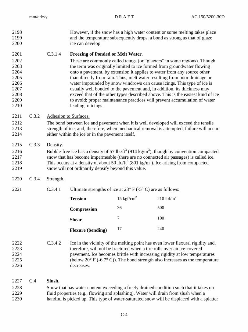
mm/dd/yy D R A F T AC 150/5200-30D
C-4
However, if the snow has a high water content or some melting takes place 2198
and the temperature subsequently drops, a bond as strong as that of glaze 2199
ice can develop. 2200
C.3.1.4 Freezing of Ponded or Melt Water. 2201
These are commonly called icings (or “glaciers” in some regions). Though 2202
the term was originally limited to ice formed from groundwater flowing 2203
onto a pavement, by extension it applies to water from any source other 2204
than directly from rain. Thus, melt water resulting from poor drainage or 2205
water impounded by snow windrows can cause icings. This type of ice is 2206
usually well bonded to the pavement and, in addition, its thickness may 2207
exceed that of the other types described above. This is the easiest kind of ice 2208
to avoid; proper maintenance practices will prevent accumulation of water 2209
leading to icings. 2210
C.3.2 Adhesion to Surfaces. 2211
The bond between ice and pavement when it is well developed will exceed the tensile 2212
strength of ice; and, therefore, when mechanical removal is attempted, failure will occur 2213
either within the ice or in the pavement itself. 2214
C.3.3 Density. 2215
Bubble-free ice has a density of 57 lb./ft3 (914 kg/m
3), though by convention compacted 2216
snow that has become impermeable (there are no connected air passages) is called ice. 2217
This occurs at a density of about 50 lb./ft3 (801 kg/m
3). Ice arising from compacted 2218
snow will not ordinarily densify beyond this value. 2219
C.3.4 Strength. 2220
C.3.4.1 Ultimate strengths of ice at 23° F (-5° C) are as follows: 2221
Tension 15 kgf/cm2 210 lbf/in
2
Compression 36 500
Shear 7 100
Flexure (bending) 17 240
C.3.4.2 Ice in the vicinity of the melting point has even lower flexural rigidity and, 2222
therefore, will not be fractured when a tire rolls over an ice-covered 2223
pavement. Ice becomes brittle with increasing rigidity at low temperatures 2224
(below 20° F (-6.7° C)). The bond strength also increases as the temperature 2225
decreases. 2226
C.4 Slush. 2227
Snow that has water content exceeding a freely drained condition such that it takes on 2228
fluid properties (e.g., flowing and splashing). Water will drain from slush when a 2229
handful is picked up. This type of water-saturated snow will be displaced with a splatter 2230

mm/dd/yy D R A F T AC 150/5200-30D
C-5
by a heel and toe slap-down motion against the ground.. Upon impacting a surface, 2231
such as the landing gear or underside of an airplane, the excess water will drain, and the 2232
snow will compact and frequently bond to the surface. Slush on a runway is a hazard 2233
because it— 2234
Greatly increases drag during the takeoff roll. 1.2235
Greatly reduces directional control. 2.2236
Decreases braking effectiveness. Slush can be removed by use of displacement 3.2237
plows, which are preferably fitted with rubber or polymer cutting edges (see 2238
Paragraph 4.2.2). 2239

mm/dd/yy D R A F T AC 150/5200-30D
C-6
This page intentionally left blank.2240
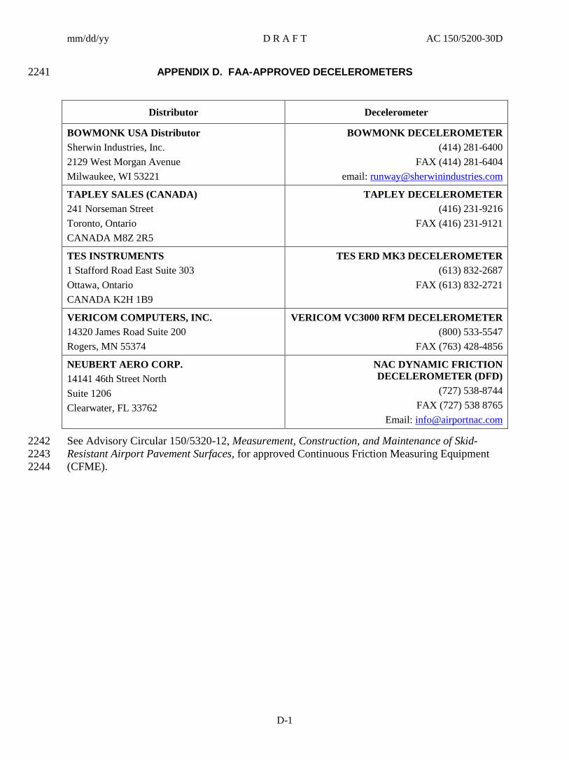
mm/dd/yy D R A F T AC 150/5200-30D
D-1
APPENDIX D. FAA-APPROVED DECELEROMETERS 2241
Distributor Decelerometer
BOWMONK USA Distributor
Sherwin Industries, Inc.
2129 West Morgan Avenue
Milwaukee, WI 53221
BOWMONK DECELEROMETER
(414) 281-6400
FAX (414) 281-6404
email: [email protected]
TAPLEY SALES (CANADA)
241 Norseman Street
Toronto, Ontario
CANADA M8Z 2R5
TAPLEY DECELEROMETER
(416) 231-9216
FAX (416) 231-9121
TES INSTRUMENTS
1 Stafford Road East Suite 303
Ottawa, Ontario
CANADA K2H 1B9
TES ERD MK3 DECELEROMETER
(613) 832-2687
FAX (613) 832-2721
VERICOM COMPUTERS, INC.
14320 James Road Suite 200
Rogers, MN 55374
VERICOM VC3000 RFM DECELEROMETER
(800) 533-5547
FAX (763) 428-4856
NEUBERT AERO CORP.
14141 46th Street North
Suite 1206
Clearwater, FL 33762
NAC DYNAMIC FRICTION
DECELEROMETER (DFD)
(727) 538-8744
FAX (727) 538 8765
Email: [email protected]
See Advisory Circular 150/5320-12, Measurement, Construction, and Maintenance of Skid-2242
Resistant Airport Pavement Surfaces, for approved Continuous Friction Measuring Equipment 2243
(CFME). 2244

mm/dd/yy D R A F T AC 150/5200-30D
D-2
This page intentionally left blank. 2245

mm/dd/yy D R A F T AC 150/5200-30D
E-1
APPENDIX E. PERFORMANCE SPECIFICATION FOR DECELEROMETERS 2246
E.1 Scope. 2247
This Appendix describes the procedures for establishing the reliability, performance, 2248
and consistency of decelerometers. 2249
E.2 Certification (General). 2250
The manufacturer will certify electronic or mechanical decelerometers are— 2251
Portable, rugged, and reliable. 1.2252
Capable of being fitted to vehicles qualified by the requirements given in this 2.2253
specification. Minimal vehicle modifications will be necessary to accommodate the 2254
mounting plates and electrical connections. Vehicles are qualified according to their 2255
size, braking and suspension system, shock absorber capabilities, and tire 2256
performance. The vehicles must have the following properties: 2257
a. Be either large sedans, station wagons, intermediate or full-sized automobiles, 2258
or utility and passenger-cargo trucks. Vehicles can be powered by front-2259
wheel, rear-wheel, or four-wheel drive. 2260
b. Be equipped with either standard disc and/or drum brakes as long as they are 2261
maintained according to the manufacturer’s performance requirements. They 2262
can also qualify if they have a single sensor ABS (anti-lock braking system) 2263
installed on the rear axle. Decelerometers should not be installed on vehicles 2264
that are equipped with full ABS because the ABS tends to distort the 2265
sensitivity of the decelerometer resulting in friction readings that are lower 2266
than actually exist. In addition, differences in ABS systems result in high 2267
variations in friction readings. This could result in the premature closing of 2268
runways. A full ABS has three sensors, one on each front wheel and one on 2269
the rear axle. Decelerometers can be installed on these vehicles only if the 2270
manufacturer of the ABS approves disengagement of the sensors on the front 2271
wheels. If this modification can be satisfactorily achieved, the vehicle’s brake 2272
system then becomes a single sensor ABS installed on the rear axle, which 2273
will then qualify the vehicle for conducting friction tests with decelerometers. 2274
c. Be equipped with heavy-duty suspension and shock absorbers to minimize the 2275
rocking or pitching motion during the application of brakes. The weight 2276
should be distributed equally to the front and rear axle of the vehicle. Ballast 2277
can be added to achieve and maintain this distribution. 2278
d. Have tires made from the same construction, composition, and tread 2279
configuration. Inflation pressure must be maintained according to the vehicle 2280
manufacturer’s specifications. When tread wear is excessive on any one tire 2281
on the vehicle and/or exceeds 75 percent of the original tread, all four tires on 2282
the vehicle must be replaced with new tires. 2283
Capable of measuring the deceleration of the vehicle from speeds greater than or 3.2284
equal to 15 mph (24 km/h) to an accuracy of 0.02 g. 2285
Capable of providing deceleration values upon request of the operator. 4.2286
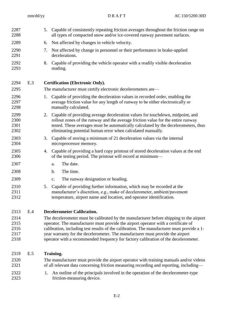
mm/dd/yy D R A F T AC 150/5200-30D
E-2
Capable of consistently repeating friction averages throughout the friction range on 5.2287
all types of compacted snow and/or ice-covered runway pavement surfaces. 2288
Not affected by changes in vehicle velocity. 6.2289
Not affected by change in personnel or their performance in brake-applied 7.2290
decelerations. 2291
Capable of providing the vehicle operator with a readily visible deceleration 8.2292
reading. 2293
E.3 Certification (Electronic Only). 2294
The manufacturer must certify electronic decelerometers are— 2295
Capable of providing the deceleration values in recorded order, enabling the 1.2296
average friction value for any length of runway to be either electronically or 2297
manually calculated. 2298
Capable of providing average deceleration values for touchdown, midpoint, and 2.2299
rollout zones of the runway and the average friction value for the entire runway 2300
tested. These averages must be automatically calculated by the decelerometers, thus 2301
eliminating potential human error when calculated manually. 2302
Capable of storing a minimum of 21 deceleration values via the internal 3.2303
microprocessor memory. 2304
Capable of providing a hard copy printout of stored deceleration values at the end 4.2305
of the testing period. The printout will record at minimum— 2306
a. The date. 2307
b. The time. 2308
c. The runway designation or heading. 2309
Capable of providing further information, which may be recorded at the 5.2310
manufacturer’s discretion, e.g., make of decelerometer, ambient/pavement 2311
temperature, airport name and location, and operator identification. 2312
E.4 Decelerometer Calibration. 2313
The decelerometer must be calibrated by the manufacturer before shipping to the airport 2314
operator. The manufacturer must provide the airport operator with a certificate of 2315
calibration, including test results of the calibration. The manufacturer must provide a 1-2316
year warranty for the decelerometer. The manufacturer must provide the airport 2317
operator with a recommended frequency for factory calibration of the decelerometer. 2318
E.5 Training. 2319
The manufacturer must provide the airport operator with training manuals and/or videos 2320
of all relevant data concerning friction measuring recording and reporting, including— 2321
An outline of the principals involved in the operation of the decelerometer-type 1.2322
friction-measuring device. 2323

mm/dd/yy D R A F T AC 150/5200-30D
E-3
Copies of pertinent ACs. 2.2324
Procedures for reporting results of the friction tests in NOTAM format.3.2325

Advisory Circular Feedback
If you find an error in this AC, have recommendations for improving it, or have suggestions for
new items/subjects to be added, you may let us know by (1) mailing this form to Manager,
Airport Safety and Operations Division, Federal Aviation Administration ATTN: AAS-300, 800
Independence Avenue SW, Washington DC 20591 or (2) faxing it to the attention of the Office
of Airport Safety and Standards at (202) 267-5383.
Subject: AC 150/5200-30D Date:
Please check all appropriate line items:
☐ An error (procedural or typographical) has been noted in paragraph on page
.
☐ Recommend paragraph ______________ on page ______________ be changed as follows:
☐ In a future change to this AC, please cover the following subject: (Briefly describe what you want added.)
☐ Other comments:
☐ I would like to discuss the above. Please contact me at (phone number, email address).
Submitted by: Date: