Dr A Sahu Dept of Comp Sc & Engg. IIT Guwahati. 8155 I/O + Timer 8155 I/O + Timer 8255 I/O 8255 I/O...
26
8254 Programmable Interval Timer Dr A Sahu Dept of Comp Sc & Engg. IIT Guwahati
-
Upload
cierra-hanthorn -
Category
Documents
-
view
219 -
download
0
Transcript of Dr A Sahu Dept of Comp Sc & Engg. IIT Guwahati. 8155 I/O + Timer 8155 I/O + Timer 8255 I/O 8255 I/O...
8254 Programmable Interval Timer
Dr A SahuDept of Comp Sc & Engg.
IIT Guwahati
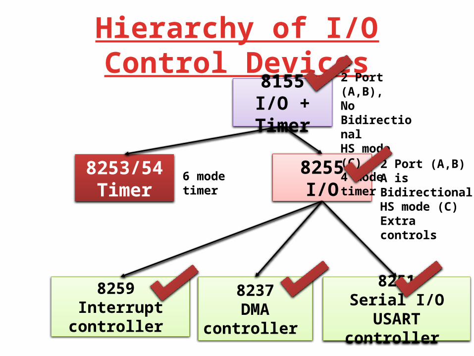
Hierarchy of I/O Control Devices8155
I/O + Timer
8255I/O
8253/54Timer
2 Port (A,B), No BidirectionalHS mode (C)4 mode timer
2 Port (A,B)A is BidirectionalHS mode (C)Extra controls
6 mode timer
8259 Interrupt controller
8237DMA controller
8251Serial I/O USART
controller
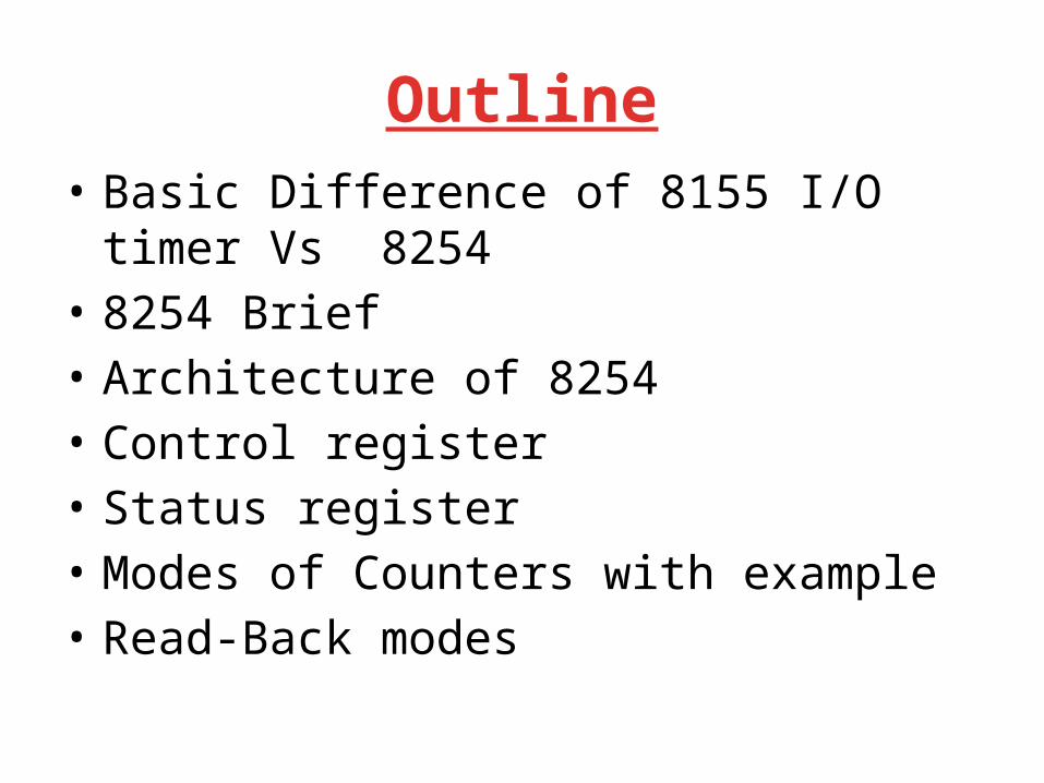
Outline• Basic Difference of 8155 I/O timer Vs 8254• 8254 Brief• Architecture of 8254• Control register• Status register • Modes of Counters with example• Read-Back modes

8155: Timer Modes Output
– 00: Single square wave of wavelength TC/2 (TC/2,TC/2 if TC even; [TC+1/2],[TC-1/2] if TC odd)
– 01: Square waves of wavelength TC (TC/2,TC/2 if TC even; [TC+1/2],[TC-1/2] if TC odd)
– 10: Single pulse on the TC'th clock pulse – 11: Single pulse on every TC'th clock pulse.
CLK
WR
Mode 00
Mode 01
Mode 10
Mode 11
N/2 N/2
N/2 N/2 N/2N/2
N
N N
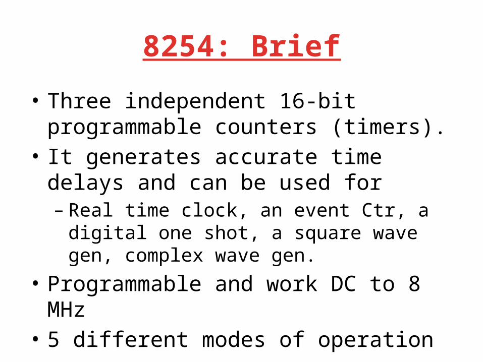
8254: Brief
• Three independent 16-bit programmable counters (timers).
• It generates accurate time delays and can be used for – Real time clock, an event Ctr, a digital one shot, a
square wave gen, complex wave gen.• Programmable and work DC to 8 MHz• 5 different modes of operation
The 8254 PIT
• The 8254 Programmable Interval-timer is used by the PC system for (1) generating timer-tick interrupts (rate is 18.2 per sec), (2) performing dynamic memory-refresh (reads ram once every 15 microseconds), and (3) generates ‘beeps’ of PC speaker
• When the speaker-function isn’t needed, the 8254 is available for other purposes
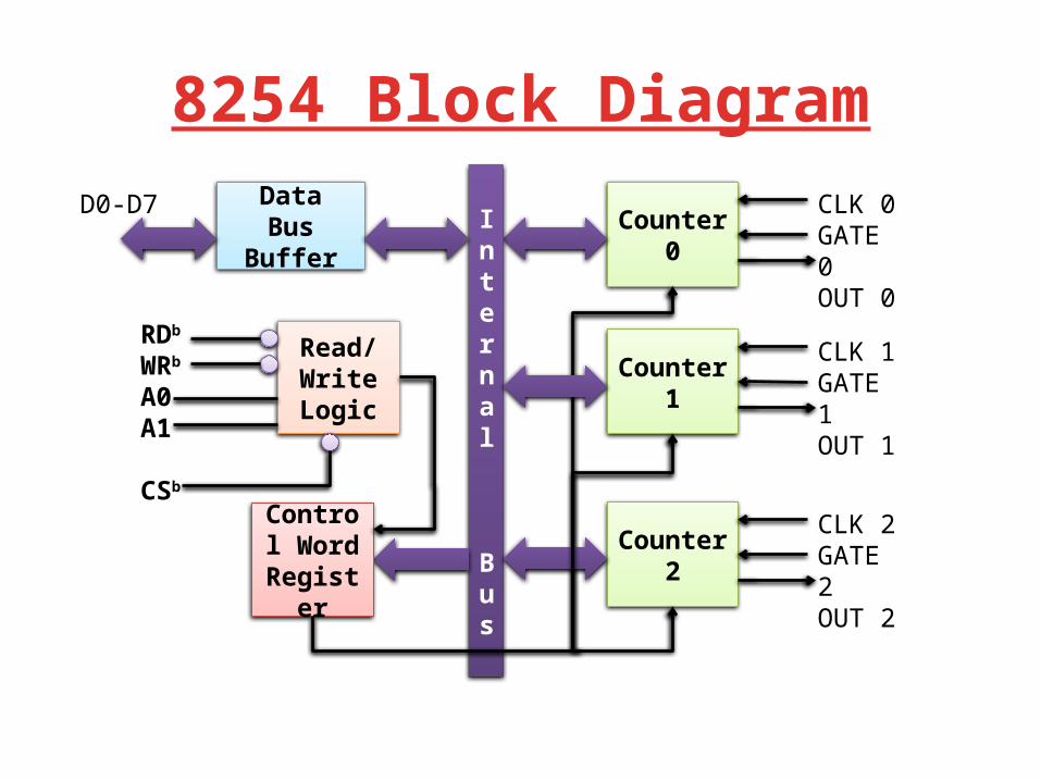
DataBus
Buffer
Read/WriteLogic
Counter0
CLK 0GATE 0OUT 0
Internal
Bus
Control Word
Register
Counter1
CLK 1GATE 1OUT 1
Counter2
CLK 2GATE 2OUT 2
D0-D7
RDb
WRb
A0A1
CSb
8254 Block Diagram
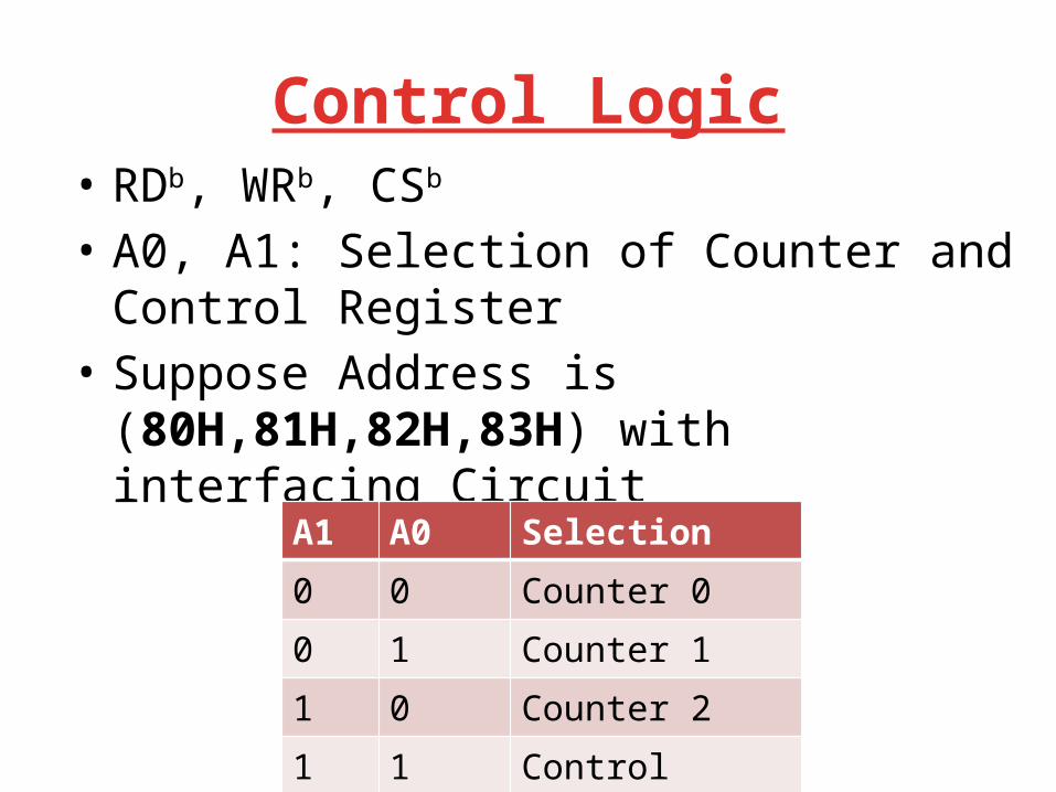
Control Logic• RDb, WRb, CSb
• A0, A1: Selection of Counter and Control Register
• Suppose Address is (80H,81H,82H,83H) with interfacing Circuit
A1 A0 Selection0 0 Counter 00 1 Counter 11 0 Counter 21 1 Control Register
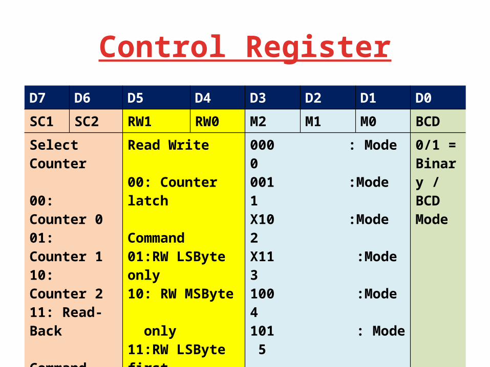
Control RegisterD7 D6 D5 D4 D3 D2 D1 D0SC1 SC2 RW1 RW0 M2 M1 M0 BCDSelect Counter
00: Counter 001: Counter 110: Counter 211: Read-Back Command
Read Write
00: Counter latch Command01:RW LSByte only10: RW MSByte only11:RW LSByte first then Msbyte
000 : Mode 0001 :Mode 1X10 :Mode 2X11 :Mode 3100 :Mode 4101 : Mode 5
0/1 =Binary / BCD Mode
Programming Counters
• Each counter may be programmed with a count of 1 to FFFFH. – Minimum count is 1 all modes except 2 and 3 with
minimum count of 2. • Each counter has a program control word
used to select the way the counter operates. – If two bytes are programmed, then the first byte
(LSB) stops the count, and the second byte (MSB) starts the counter with the new count.
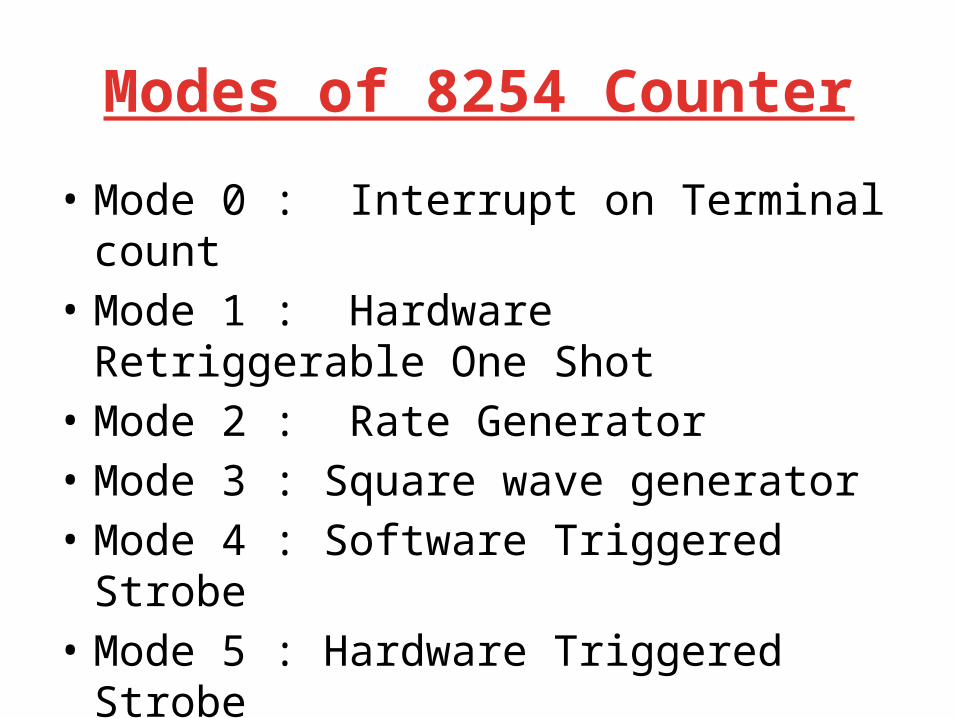
Modes of 8254 Counter
• Mode 0 : Interrupt on Terminal count • Mode 1 : Hardware Retriggerable One Shot• Mode 2 : Rate Generator• Mode 3 : Square wave generator• Mode 4 : Software Triggered Strobe• Mode 5 : Hardware Triggered Strobe
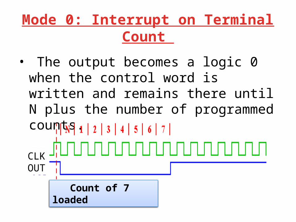
Mode 0: Interrupt on Terminal Count
• The output becomes a logic 0 when the control word is written and remains there until N plus the number of programmed counts.
CLKOUT
Count of 7 loaded
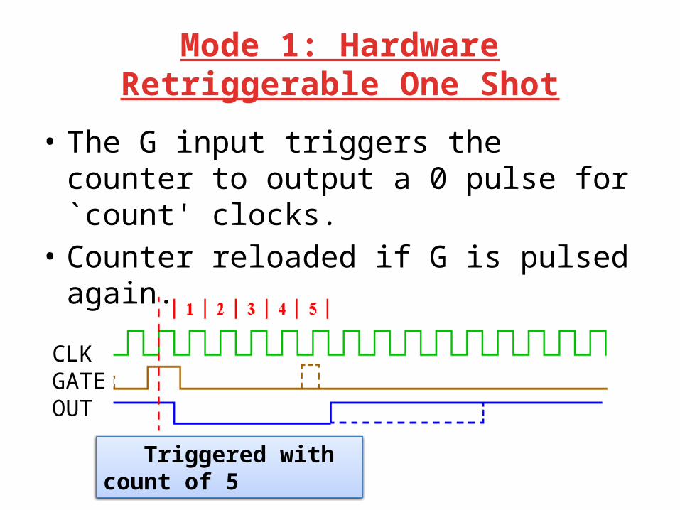
Mode 1: Hardware Retriggerable One Shot
• The G input triggers the counter to output a 0 pulse for `count' clocks.
• Counter reloaded if G is pulsed again.
CLKGATEOUT
Triggered with count of 5

Mode 2: Rate Generator• Counter generates a series of pulses 1 clock
pulse wide. • The separation between pulses is determined
by the count. • The cycle is repeated until reprogrammed or G
pin set to 0.
CLKOUT
Count of 5 loaded
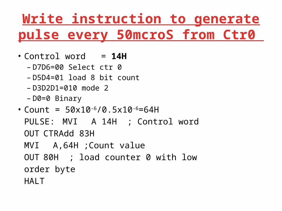
Write instruction to generate pulse every 50mcroS from Ctr0
• Control word = 14H– D7D6=00 Select ctr 0– D5D4=01 load 8 bit count – D3D2D1=010 mode 2 – D0=0 Binary
• Count = 50x10-6/0.5x10-6=64HPULSE: MVI A 14H ; Control word
OUT CTRAdd 83HMVI A,64H ;Count valueOUT 80H ; load counter 0 with low
order byteHALT

Mode 3: Square wave generator
• Generates a continuous square-wave with G set to 1.
• If count is even, 50% duty cycle otherwise OUT is high 1 cycle longer
CLKOUT
Count of 6 loaded
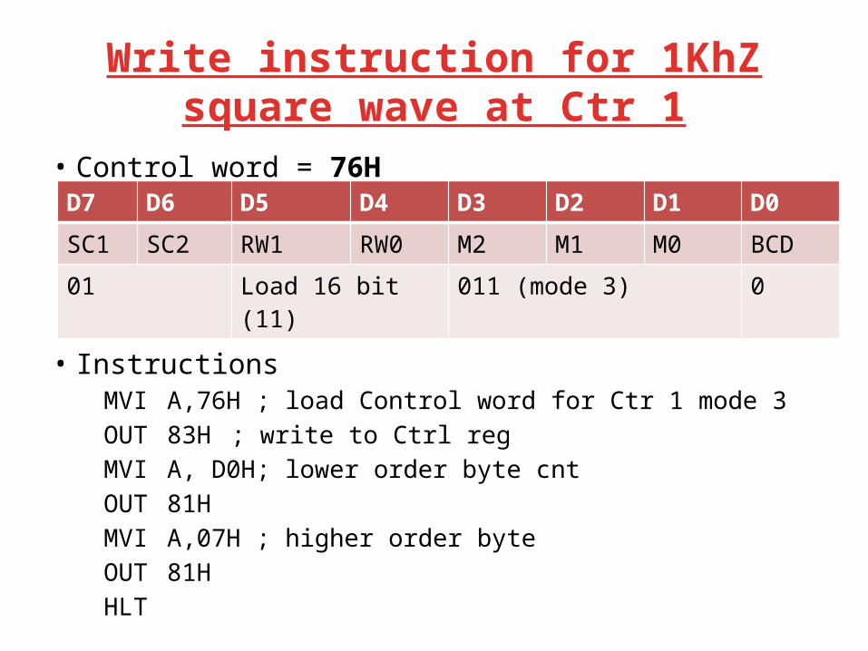
Write instruction for 1KhZ square wave at Ctr 1
• Control word = 76H
• Count= 1x10⁻³/0.5x10-6=2000=07D0H• Instructions
MVI A,76H ; load Control word for Ctr 1 mode 3OUT 83H ; write to Ctrl regMVI A, D0H; lower order byte cnt OUT 81HMVI A,07H ; higher order byte OUT 81HHLT
D7 D6 D5 D4 D3 D2 D1 D0SC1 SC2 RW1 RW0 M2 M1 M0 BCD01 Load 16 bit (11) 011 (mode 3) 0
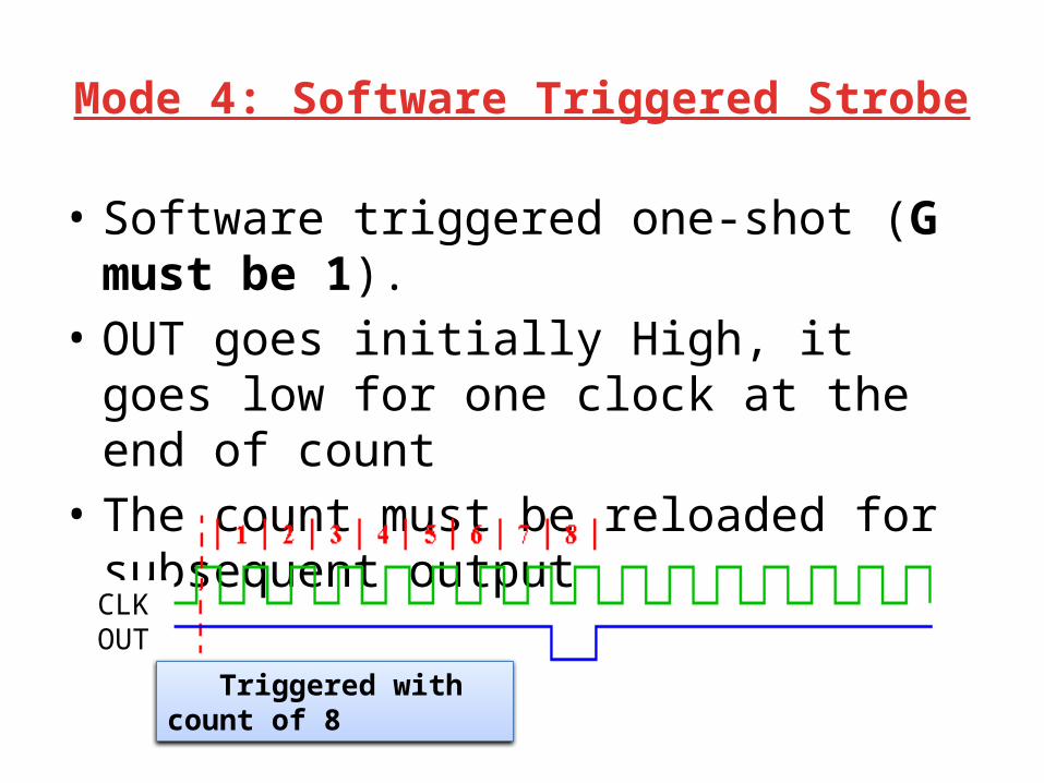
Mode 4: Software Triggered Strobe
• Software triggered one-shot (G must be 1).• OUT goes initially High, it goes low for one
clock at the end of count• The count must be reloaded for subsequent
output
CLKOUT
Triggered with count of 8
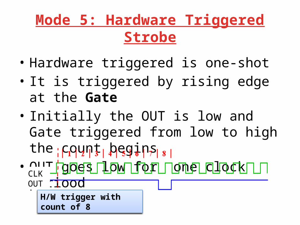
Mode 5: Hardware Triggered Strobe
• Hardware triggered is one-shot• It is triggered by rising edge at the Gate• Initially the OUT is low and Gate triggered
from low to high the count begins • OUT goes low for one clock periood
H/W trigger with count of 8
CLKOUT

Gate Setting of Counter Modes Low or
Going LowRising High
Mode 0 Disable Counting - Enable Counting
Mode 1 ----- 1. Initiate Counting2. Reset O/P after next Clock
---
1. Disable counting 2. Set O/P immediately
high
1. Reloads Counter2. Initiate Counting
Enable Counting
1. Disable counting 2. Set O/P immediately
high
Initiates Counting Enable Counting
Disable Counting Enable Counting
Initiates Counting
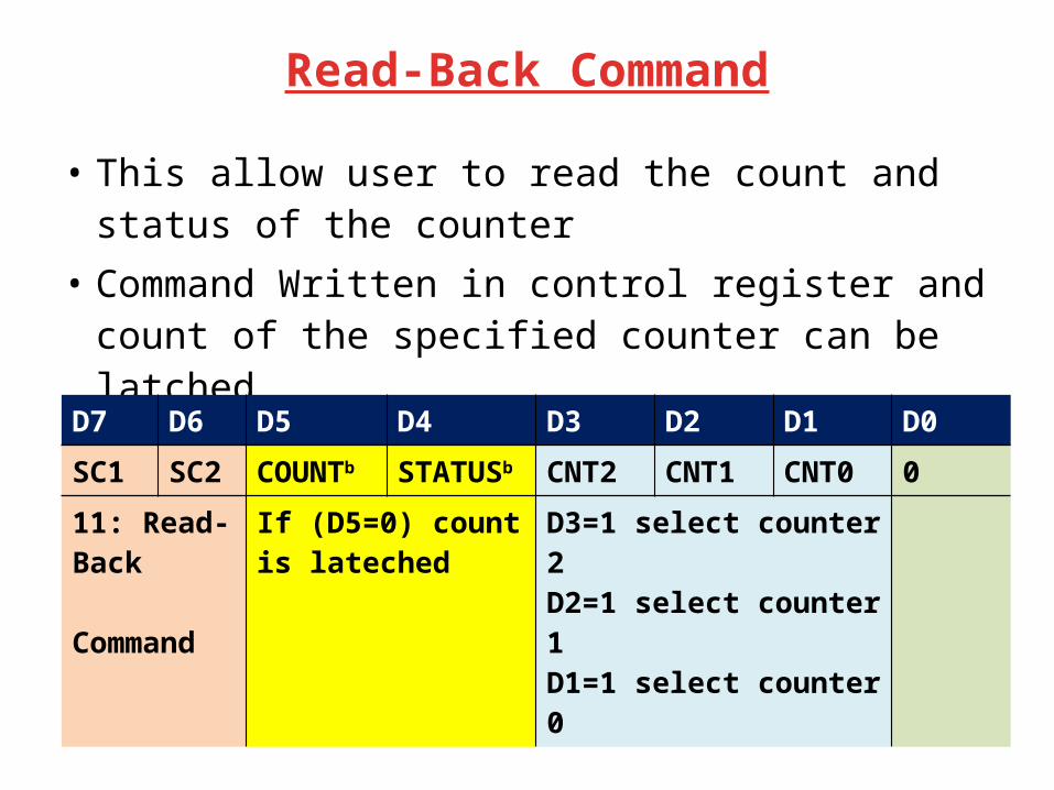
Read-Back Command
• This allow user to read the count and status of the counter
• Command Written in control register and count of the specified counter can be latched
• Control word 11 01 011 0 (D6H) in control word will latch the count of CNT0 & CNT1
D7 D6 D5 D4 D3 D2 D1 D0SC1 SC2 COUNTb STATUSb CNT2 CNT1 CNT0 011: Read-Back Command
If (D5=0) count is lateched
D3=1 select counter 2D2=1 select counter 1D1=1 select counter 0
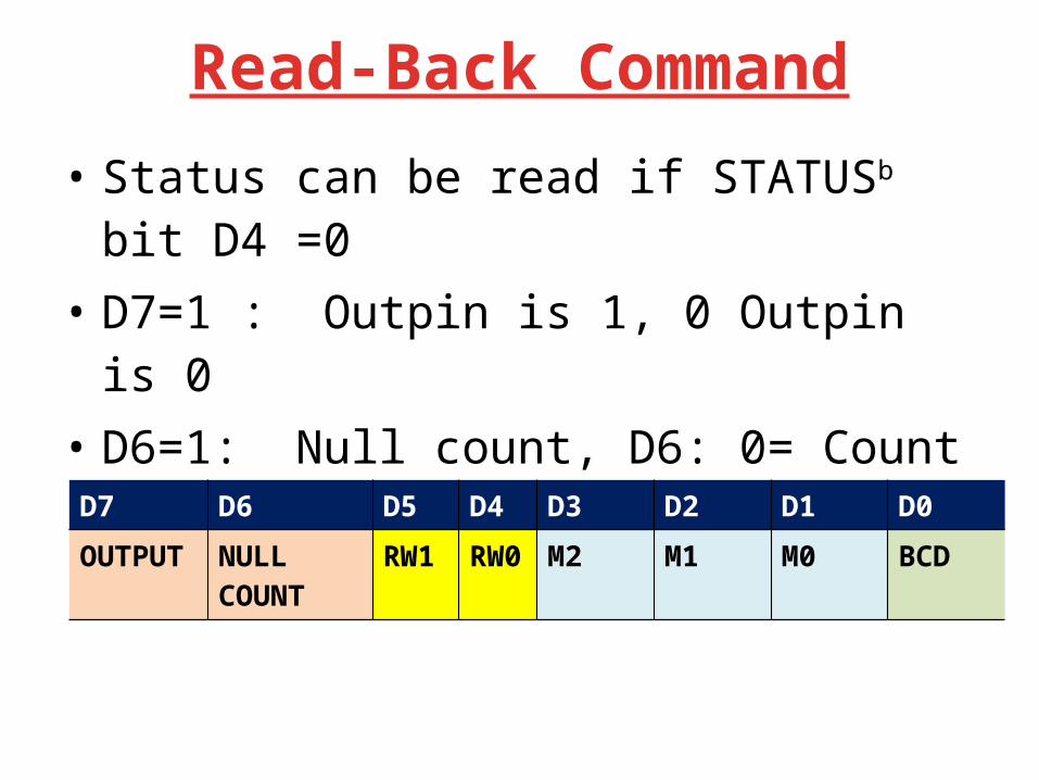
Read-Back Command
• Status can be read if STATUSb bit D4 =0• D7=1 : Outpin is 1, 0 Outpin is 0• D6=1: Null count, D6: 0= Count available for
reading• D5-D0:Counter Programmed mode
D7 D6 D5 D4 D3 D2 D1 D0OUTPUT NULL
COUNTRW1 RW0 M2 M1 M0 BCD

Write a SR to generate an interrupt every 1 Second
• Assume Clock Freq=2MhZ• Count is too large • Counter 1 load with 50,000 to generate 25ms– CNTLOAD=50,00010=C350H
• Counter 2 load with 40 to generate 25msX40=-1S pulse (CNTLOAD=4010=28H)
• Counter1 input is to counter 2• Both Counter 1 & Counter 2 in Mode 2
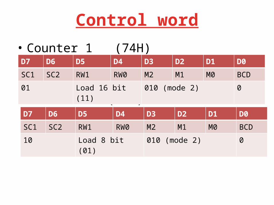
Control word
• Counter 1 (74H)
• Counter 2 (94H)
D7 D6 D5 D4 D3 D2 D1 D0SC1 SC2 RW1 RW0 M2 M1 M0 BCD01 Load 16 bit (11) 010 (mode 2) 0
D7 D6 D5 D4 D3 D2 D1 D0SC1 SC2 RW1 RW0 M2 M1 M0 BCD10 Load 8 bit (01) 010 (mode 2) 0
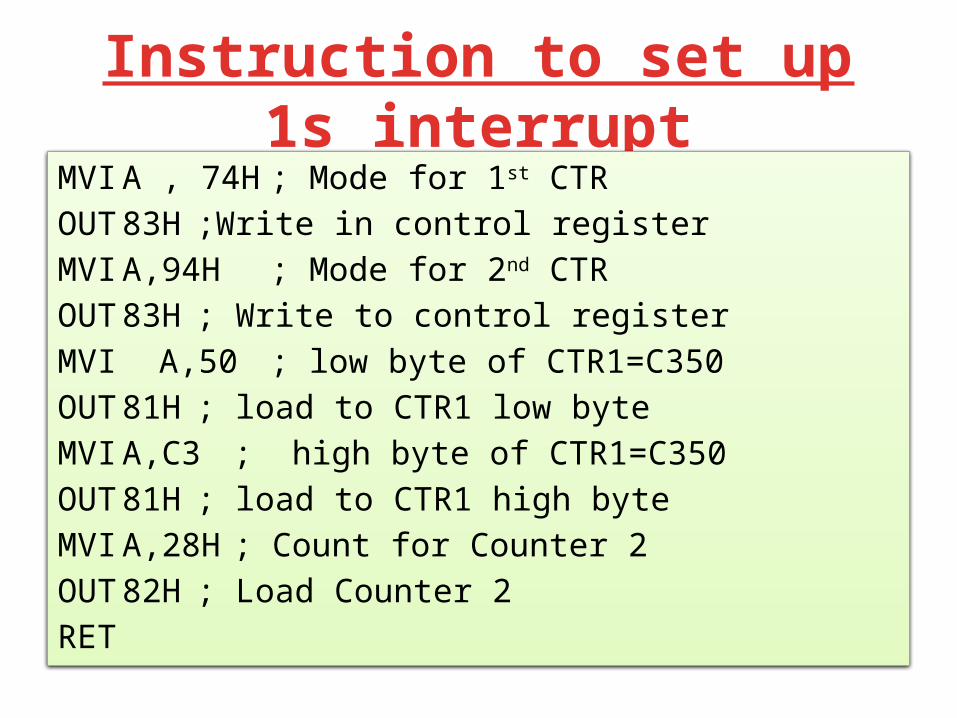
Instruction to set up 1s interruptMVI A , 74H ; Mode for 1st CTROUT 83H ;Write in control registerMVI A,94H ; Mode for 2nd CTROUT 83H ; Write to control register MVI A,50 ; low byte of CTR1=C350OUT 81H ; load to CTR1 low byteMVI A,C3 ; high byte of CTR1=C350OUT 81H ; load to CTR1 high byteMVI A,28H ; Count for Counter 2OUT 82H ; Load Counter 2RET

Thanks