
Dr. A. R. Ganesan - Institute for Astronomy · the retina of the human eye, microscopy, etc...
35
Indigenous Development and Characterization of a closed loop Adaptive Optics system for Wavefront Control Dr. A. R. Ganesan Associate Professor Department of Physics Indian Institute of Technology Madras Chennai – 600 036 [email protected]
Transcript of Dr. A. R. Ganesan - Institute for Astronomy · the retina of the human eye, microscopy, etc...

Indigenous Development and Characterization of a closed loop Adaptive Optics system for
Wavefront Control
Dr. A. R. GanesanAssociate Professor
Department of PhysicsIndian Institute of Technology Madras
Chennai – 600 [email protected]

• Adaptive Optics (AO) is an emerging branch of Opticswherein the optics modifies itself to changingenvironmental conditions to provide high resolutionimagery.
• This concept started towards improving the astronomicalimages obtained with ground based telescopes.
• The Optical turbulence due to random refractive indexfluctuations of the atmosphere (caused by factors suchas pressure, temperature), induces several aberrations inthe wavefront resulting in loss of resolution. AO wasaimed at nullifying this effect.
• Today, the applications of Adaptive Optics range fromAstronomical imaging to laser beam steering in free spacesatellite optical communication, high resolution imaging ofthe retina of the human eye, microscopy, etc
Introduction

Input Phase
Phase Sensor
PhaseReconstructor
Tilt Mirror Loop
Deformable Mirror Loop
Output Phase
Tilt Mirror
DeformableMirror
A typical Adaptive Optics System
An Adaptive Optics system consists of a Wavefront Phase sensor,a Steering mirror and a Deformable mirror. The phase profile iscontinuously measured and corrected in real-time.

If W(x,y) represents a wavefront, then partial derivative of it is given as
W(x,y)/ x = x/f W(x,y)/ y = y/f,
where - f is the focal length of the lenslet
array- x & y are the shift of spots along
x & y directions. A typical spot-pattern
Phase Profile measurement by Shack-Hartmann Principle

• There are two approaches for Wavefront Reconstruction –Modal and Zonal
• The Modal reconstruction scheme treats the wavefront (WF) as the sum of a series of basis functions. The method reconstructs the WF within a circular mask & whose output is a set of Zernike polynomial.
• It represents a WF as a series of whole aperture functions of increasing complexity.
Wavefront Reconstruction
• The Zonal reconstruction approach divides the aperture into an array of independent sub-apertures or zones.
• This allows us to generate actuator commands directly from the measured gradients without actually reconstructing the wavefront in the process.

Work on AO started in the year 2000 with the development of anIndigenous Adaptive Optics system for DRDO, with a grant from IRDE under Phase-I of the National Program on Photonics.
Under this project, a Wavefront Sensor (WFS) was designed and developed at REC / NIT, Trichy.
Custom made software was developed for real time measurement of wavefront aberrations and several features were incorporated in this.
This WFS was then integrated with the tip-tilt mirror anddeformable mirror at IRDE to form a closed loop system
Development of indigenous AO system

Optical Layout of WFS
S1,S2 micro controlled stepper motor shutters, M1 –Mirror, L1,L2,L3, - lenses,SPF-Spatial Filter, NDF-Neutral density filter, BS-Beam splitter, MLA-Microlens Array.

Photograph of the WFS Optical System developed

WFS (Total System)
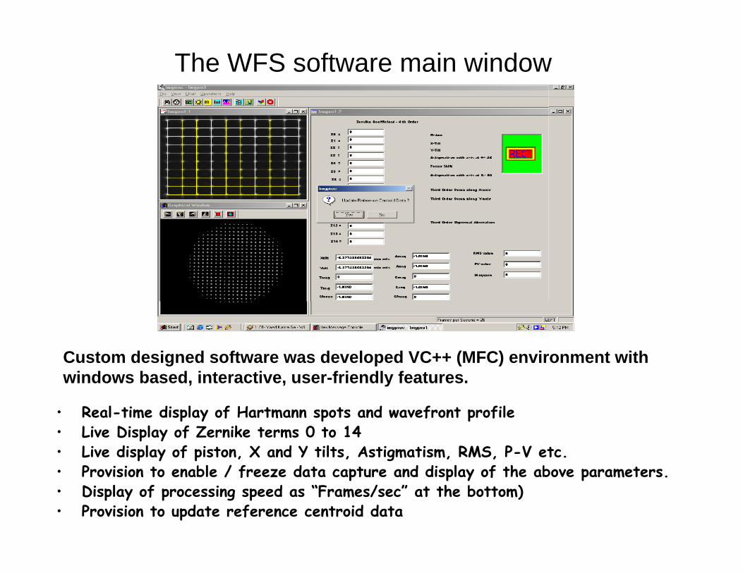
The WFS software main window
Custom designed software was developed VC++ (MFC) environment with windows based, interactive, user-friendly features.
• Real-time display of Hartmann spots and wavefront profile• Live Display of Zernike terms 0 to 14• Live display of piston, X and Y tilts, Astigmatism, RMS, P-V etc.• Provision to enable / freeze data capture and display of the above parameters.• Display of processing speed as “Frames/sec” at the bottom)• Provision to update reference centroid data

Collimation testing
• Alignment and collimation checking by a pre-computed grid overlay on the imaging window, and possible automated adjustments until the spots coincide with grid crossings
Features

Sub-aperture Intensity Distribution
• Focus checking by display of intensity profile of any sub-aperture in the graphic window, and possible automated adjustments until the beam profile is narrow and has a sharpest peak
Features

Line Intensity Profile
• Intensity checking by display of line profile, and possible automated adjustments to ensure that the intensities are in the linear range of the detector, to avoid saturation
Features

X-Tilt

Y-Tilt

Wavelength of Operation : 400 –700nmSub-aperture for analysis : 16 x 16Acquisition Frequency : 25 frames/secTilt measurement Accuracy : 1.9 radiansMax. Tilt measurement range : ± 2m radianWavefront Measurement : λ/50Pupil shape : Square
Specifications of the Wavefront Sensor

Applied tilt Vs Measured tilt using SHWFS

Closed loop tilt measurement / compensation setup

Actuator commands for steering mirror are generated to compensate the tilt
Wavefront Compensation for global tilt
240 micro radian 2-axis tilt
Corrected
A.R. Ganesan et al, IETE J. of Res., 52, 6, 417-424 (2006)

Closed loop DM characterization

• Actuator commands for the deformable mirror are generated tocorrect aberration
• The shape of the reflective membrane is controlled by control voltagesto the membrane electrodes
Wavefront Compensation for local tilt
Distorted wavefront
Corrected
A.R. Ganesan et al, J. of Optics, 34, 2, 67-81 (2005)

Wavefront Error correction – a typical result
Wavefront error
Reference Wavefront
AberratedWavefront
DM corrected
Wavefront
X tilt (mic.Rad) 0.56411 32.903 -5.34336
Y tilt(mic.Rad) 0.73315 -31.20003 14.83812S focus (m) 0.47368 23.45838 -5.31588Amag -0.94768 -46.92201 10.63284Cmag 0.03697 0.037 0.01449Spmag 1.73026 4.96 -1.4102rms (nm) 3.46462 8.1043 16.58731PV (nm) 1.80323 47.42245 11.53924

Work on Adaptive Optics in Vision Science
• Ophthalmoscopy - Retinal imaging - Focusing lasers
• Eye has an imaging optics (lens + cornea combination)• The image quality at the retina depends on the aberration of this optics
• Lower Order Aberrations:– Defocus, Astigmatism (~92%)– Can be corrected by Spectacles/ Contact lenses
• Higher Order Aberrations:– Spherical aberration, Coma, Trefoil.. (~8%)– Can be corrected by customized surgeries or one has to look for
Adaptive Optics

PC
CCD
L6
L5
L3
L4
L1
L2
SFDF
LASER
Eye
D1
D2
D3
B5
Experimental Setup
As a first step, the WFS was used to measure the aberration content in human eye

Analysis of Higher Order aberrationsof Normal Eye
- HO Aberrations of Human eye were measured for a age group of 20 - 30 yrs.
- All of them had normal vision (6/6)- Acuity test was done using a snellen chart- Subjects were dilated using tropicamide eye drops
for pupil elongation- Tested for both 6mm pupil size

Wavefront Error
With defocus Without defocus Removing LOAIntensity Profile and Interferogram for pupil size 6mm
with and without defocus
M. Jesson, P. Arulmozhivarman and A.R. Ganesan, Asian J. of Ophthalmology, 6, 2, 10-16 (2004)
0.5
0.6
0.7
0.8
0.9
1
2 3 4 5 6 7 8
Pupil SizeSt
rehl
ratio
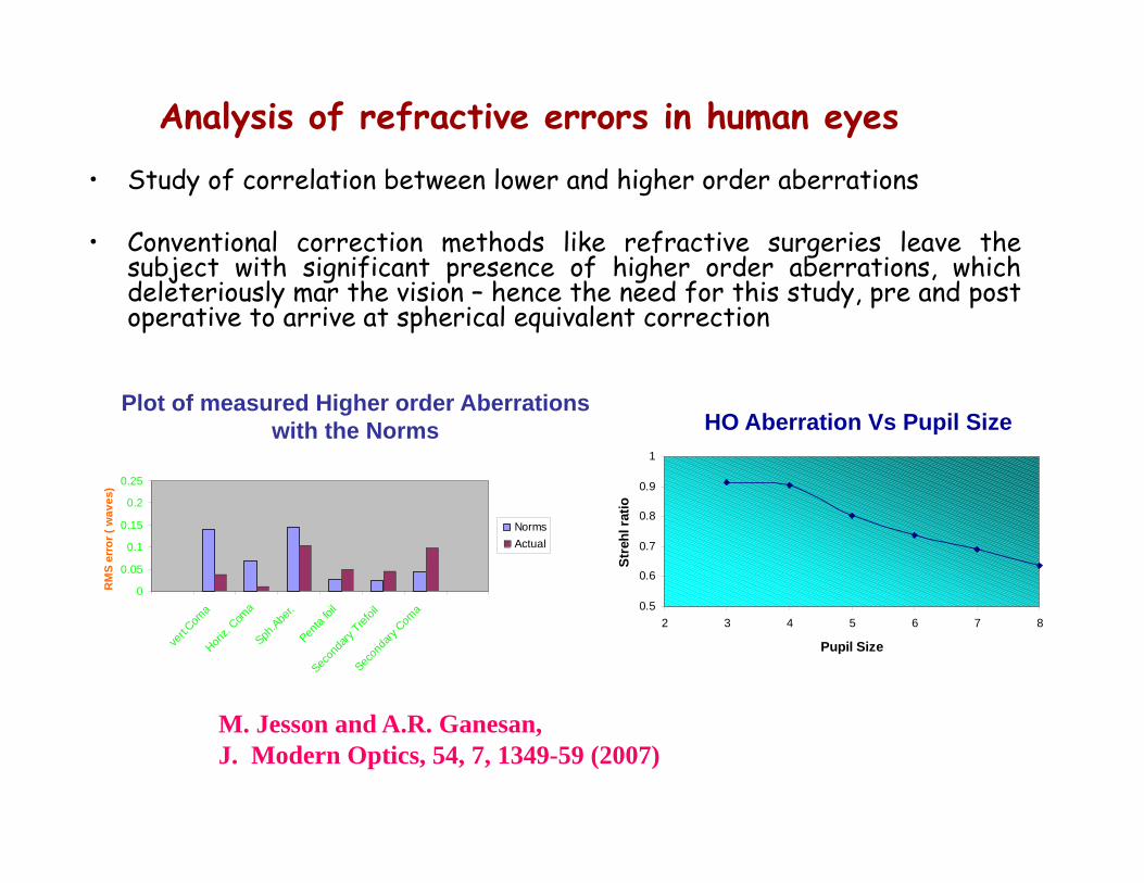
• Study of correlation between lower and higher order aberrations
• Conventional correction methods like refractive surgeries leave thesubject with significant presence of higher order aberrations, whichdeleteriously mar the vision – hence the need for this study, pre and postoperative to arrive at spherical equivalent correction
M. Jesson and A.R. Ganesan, J. Modern Optics, 54, 7, 1349-59 (2007)
HO Aberration Vs Pupil Size
0
0.05
0.1
0.15
0.2
0.25
vert.C
oma
Horiz.
Coma
Sph.Abe
r.Pen
ta foi
l
Secon
dary
Trefoil
Secon
dary
Coma
RM
S er
ror (
wav
es)
NormsActual
Plot of measured Higher order Aberrations with the Norms
Analysis of refractive errors in human eyes

Analysis of aberration caused by the Intervening medium in the line of Sight
• Intervening mediums affect the quality of images. For instance, seeingthrough a helmet visor, windscreen or windshield of a car or an aircraftdegrades the image quality of a scenery when compared to seeing with thenaked eye.
• A simple and a novel technique for the measurement of aberrations intransparent materials like glass sheets, perspex etc has been developed.
Shack-Hartmann Technique The new Spot-Pattern Test Chart Technique
A.R. Ganesan et al, J. of Meas. Sci. & Technol., 16, 2534-40 (2005)
Large size optics testable easilyInterferometry also can be used, but beam size is limited
Proposed to apply for patent

Measurement of Moments or Centroiding using various methods
P. Arulmozhivarman, L. Praveen Kumar and A.R. Ganesan, Optik, Intl. J. of Laser & Electro-Optics, 117, 82-87 (2006)
• Centroid estimation in Shack-Hartmann wavefront sensing plays vital role in phase estimation.
• AO correction being more accurate depends on how finely we are estimating the wavefront error in terms of pixel scale, processing time and accuracy.
new

Development of Wavelet Based Wavefront Sensing and Characterization under DRDO project
• Wavelet Based Wavefront Sensing has the advantages of variableresolution, and trade off between accuracy, resolution and speed
• A full fledged system will be developed based on this, including a closedloop imaging system to work at 100 Hz, and tried with far field imaging
• The WFS software has been modified incorporating Wavelet methodfor centroid estimation with multi resolution.
• We have applied Haar wavelet transformation on the image such thatthe image is decomposed into 4 different bands (frequency data)namely LL, HL, LH, and HH.
• More decomposition is possible with data in LL band which will increasethe speed of centroid calculation but the resolution of the image maydecrease.
Current Works

Tilt Measurement with Statistical averaging
64 frames / secGiven tilt 590 microrad
Measured tilt 561 microrad

Tilt Measurement with Wavelet method
83 frames / secGiven tilt
590 microradMeasured tilt 593 microrad

Characterization and correction of Foveal and Parafoveal Aberrations in Human Eye using
Adaptive Optics under DST project
• Foveal and Parafoveal aberrations in the Human Eye shall be measuredon patients with and without foveal vision loss
• The visual functions, retinal stimulus and perceptual preference shall beassessed without / altered / with adaptive aberration compensation
• Expected outcome would be aberration combination for best subjectivefocus and improved vision for patients with foveal loss by using customdesigned spectacles
(In Collaboration with Sankara Nethralaya, Chennai)
Schematic of Proposed Setup
for Vision studies

Significant outcomes of the proposed project
• Establishment of combination of aberrations that results in subjective best focus for foveal images– Spectacle manufacturing companies are already working on
customized aberration corrected lenses– Results of this study would help to improve these products
for improvement in quality of vision• Establishment of the possibility of correction of parafoveal
aberrations in subjects with vision loss gives enormous HOPE for better vision for people with this defect– The results of this study could motivate manufacturers to
produce customized parafoveal aberration corrected spectacles for people with foveal vision loss