Financial Close & Compliance Automation for Midsize Companies

xx
DPODSPTDisplayPort Source Compliance Test AutomationSoftware for DPO70000 and DSA70000 Series Oscilloscopes
ZZZ
Instructions
*P077018601*
077-0186-01

DPODSPTDisplayPort Source Compliance Test AutomationSoftware for DPO70000 and DSA70000 Series Oscilloscopes
ZZZ
Instructions
xx
Revision A
www.tektronix.com077-0186-01
Copyright © Tektronix. All rights reserved. Licensed software products are owned by Tektronix or its subsidiariesor suppliers, and are protected by national copyright laws and international treaty provisions.
Tektronix products are covered by U.S. and foreign patents, issued and pending. Information in this publicationsupersedes that in all previously published material. Specifications and price change privileges reserved.
TEKTRONIX and TEK are registered trademarks of Tektronix, Inc.
DPODSPT DisplayPort Transmitter Compliance Test Automation Software Version 1.2
Acknowledgements: iTextSharp Library Copyright © 1997-2007 by Bruno Lowagie. The iTextSharp Library isfreely available at http://itextsharp.sourceforge.net
Contacting Tektronix
Tektronix, Inc.14200 SW Karl Braun DriveP.O. Box 500Beaverton, OR 97077USA
For product information, sales, service, and technical support:In North America, call 1-800-833-9200.Worldwide, visit www.tektronix.com to find contacts in your area.

Table of Contents
Prerequisites. . . . . . . . . . . . . . . . . . . . . . . . . . . . . . . . . . . . . . . . . . . . . . . . . . . . . . . . . . . . . . . . . . . . . . . . . . . . . . . . . . . . . . . . . . . . . . . . . . . . . . . . . 1Instrument Connection .. . . . . . . . . . . . . . . . . . . . . . . . . . . . . . . . . . . . . . . . . . . . . . . . . . . . . . . . . . . . . . . . . . . . . . . . . . . . . . . . . . . . . . . . . . . . 1About the Application Software . . . . . . . . . . . . . . . . . . . . . . . . . . . . . . . . . . . . . . . . . . . . . . . . . . . . . . . . . . . . . . . . . . . . . . . . . . . . . . . . . . 2Compliance Testing . . . . . . . . . . . . . . . . . . . . . . . . . . . . . . . . . . . . . . . . . . . . . . . . . . . . . . . . . . . . . . . . . . . . . . . . . . . . . . . . . . . . . . . . . . . . . . . 13Oscilloscope Probe or Cable Calibration . . . . . . . . . . . . . . . . . . . . . . . . . . . . . . . . . . . . . . . . . . . . . . . . . . . . . . . . . . . . . . . . . . . . . . . 14
DPODSPT DisplayPort Software i
Table of Contents
ii DPODSPT DisplayPort Software

PrerequisitesTektronix DPO70804/B, DSA70804/B, DPO71254/B, DSA71254/B,DPO71604/B, DSA71604/B, DPO72004/B, or DSA72004/B oscilloscope.
A minimum of 20 minutes warm-up time for the oscilloscope.
Run SPC (Signal Path Compensation) to assure accuracy of the acquisitionsystem. Remove all probes from the oscilloscope before running SPC.
Perform deskew to compensate for skew between measurement channels.Note that it is critical to select Off for the Display Only control in the deskewsetup window to include the deskew data with saved waveforms.
Terminate all unused connections on the DisplayPort test fixture with 50 Ωterminators.
Up-to-date versions of the TekScope and DPOJET applications are requiredto ensure best operation of this software. The readme file for DPODSPT hasinformation on the required versions. Ensure that these versions (or later)are installed on your oscilloscope; update them from www.tektronix.comif necessary.
10 GB available hard drive space recommended.
NOTE. A secondary monitor is recommended (but not required) to display theoscilloscope application and DisplayPort application simultaneously on separatemonitors, for ease of use.
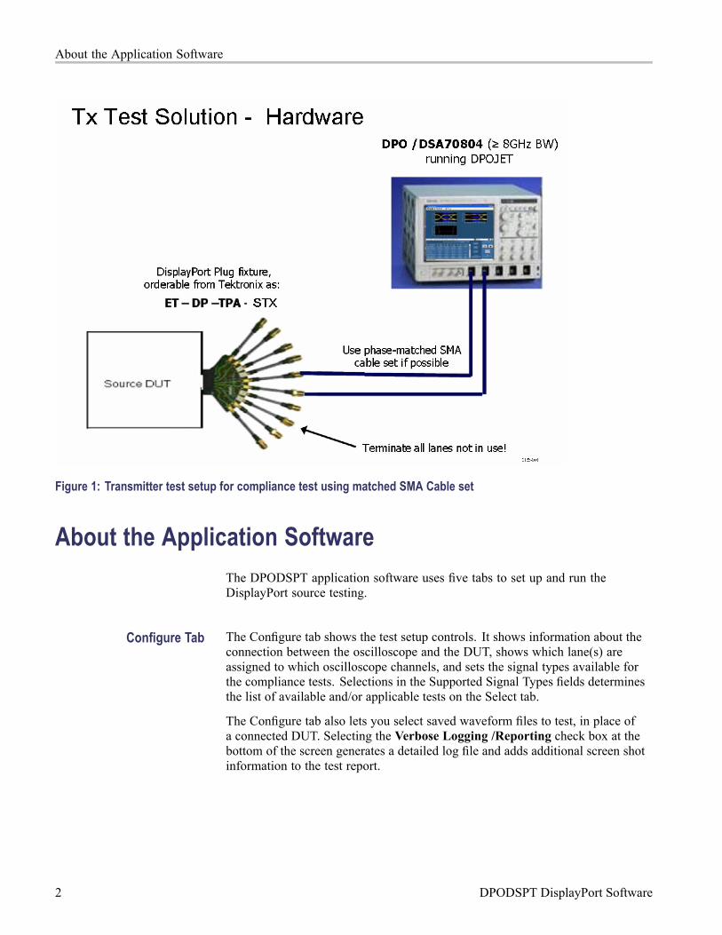
Instrument ConnectionThe DPODSPT software can perform testing on a DisplayPort sourcedevice-under-test (DUT) or on stored waveforms. Direct connection to the DUTrequires at least one skew-matched pair of SMA cables, two or more TCA-SMAconnectors, and the DisplayPort test fixture. The test fixture is available fromTektronix as part number ET-DP-TPA-STX.
Differential probes P7380SMA or P7313SMA can also be used, and include theirown phase-matched SMA cable sets. If probes are not used, phase-matched SMAcable sets are available from Tektronix as part number 174-4944-01.
Connect oscilloscope channels CH1 and CH2 to the DisplayPort lane to be tested.You can optionally connect oscilloscope channels CH3 and CH4 to anotherDisplayPort lane for inter-pair lane skew testing. Any unused connections on theDisplayPort test fixture must be terminated with 50 Ω terminators.
DPODSPT DisplayPort Software 1
About the Application Software
Figure 1: Transmitter test setup for compliance test using matched SMA Cable set
About the Application SoftwareThe DPODSPT application software uses five tabs to set up and run theDisplayPort source testing.
Configure Tab The Configure tab shows the test setup controls. It shows information about theconnection between the oscilloscope and the DUT, shows which lane(s) areassigned to which oscilloscope channels, and sets the signal types available forthe compliance tests. Selections in the Supported Signal Types fields determinesthe list of available and/or applicable tests on the Select tab.
The Configure tab also lets you select saved waveform files to test, in place ofa connected DUT. Selecting the Verbose Logging /Reporting check box at thebottom of the screen generates a detailed log file and adds additional screen shotinformation to the test report.
2 DPODSPT DisplayPort Software
About the Application Software
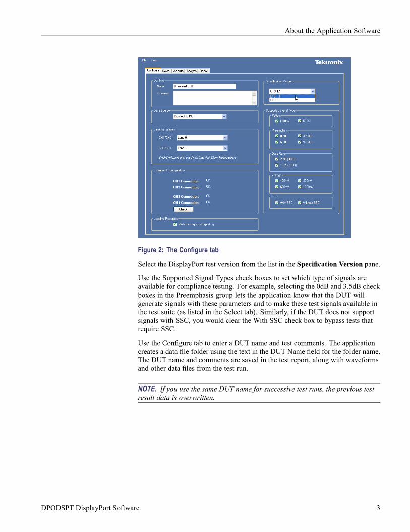
Figure 2: The Configure tab
Select the DisplayPort test version from the list in the Specification Version pane.
Use the Supported Signal Types check boxes to set which type of signals areavailable for compliance testing. For example, selecting the 0dB and 3.5dB checkboxes in the Preemphasis group lets the application know that the DUT willgenerate signals with these parameters and to make these test signals available inthe test suite (as listed in the Select tab). Similarly, if the DUT does not supportsignals with SSC, you would clear the With SSC check box to bypass tests thatrequire SSC.
Use the Configure tab to enter a DUT name and test comments. The applicationcreates a data file folder using the text in the DUT Name field for the folder name.The DUT name and comments are saved in the test report, along with waveformsand other data files from the test run.
NOTE. If you use the same DUT name for successive test runs, the previous testresult data is overwritten.
DPODSPT DisplayPort Software 3
About the Application Software
Select Tab The Select tab lists the available tests.
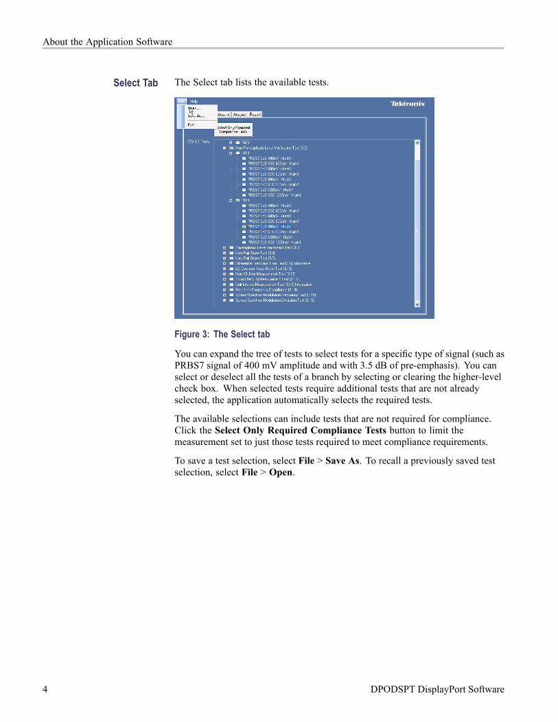
Figure 3: The Select tab
You can expand the tree of tests to select tests for a specific type of signal (such asPRBS7 signal of 400 mV amplitude and with 3.5 dB of pre-emphasis). You canselect or deselect all the tests of a branch by selecting or clearing the higher-levelcheck box. When selected tests require additional tests that are not alreadyselected, the application automatically selects the required tests.
The available selections can include tests that are not required for compliance.Click the Select Only Required Compliance Tests button to limit themeasurement set to just those tests required to meet compliance requirements.
To save a test selection, select File > Save As. To recall a previously saved testselection, select File > Open.
4 DPODSPT DisplayPort Software
About the Application Software
NOTE. The oscilloscope must have the same hardware and probe configurationthat was used to create the saved test. For example, tests saved using TCASMAconnectors cannot be run on an oscilloscope that is using differential probes.Recalling a file with this sort of mismatch results in no tests being available onthe Select tab.
The tree of tests is built based on the supported signal types selected in theConfigure tab. Any change in the Configure tab settings resets the test selectionsettings.
Stored waveforms and other data from a test session can fill several GB of harddisk space. You may need to move data to a higher-capacity storage area whenrunning many test sessions.
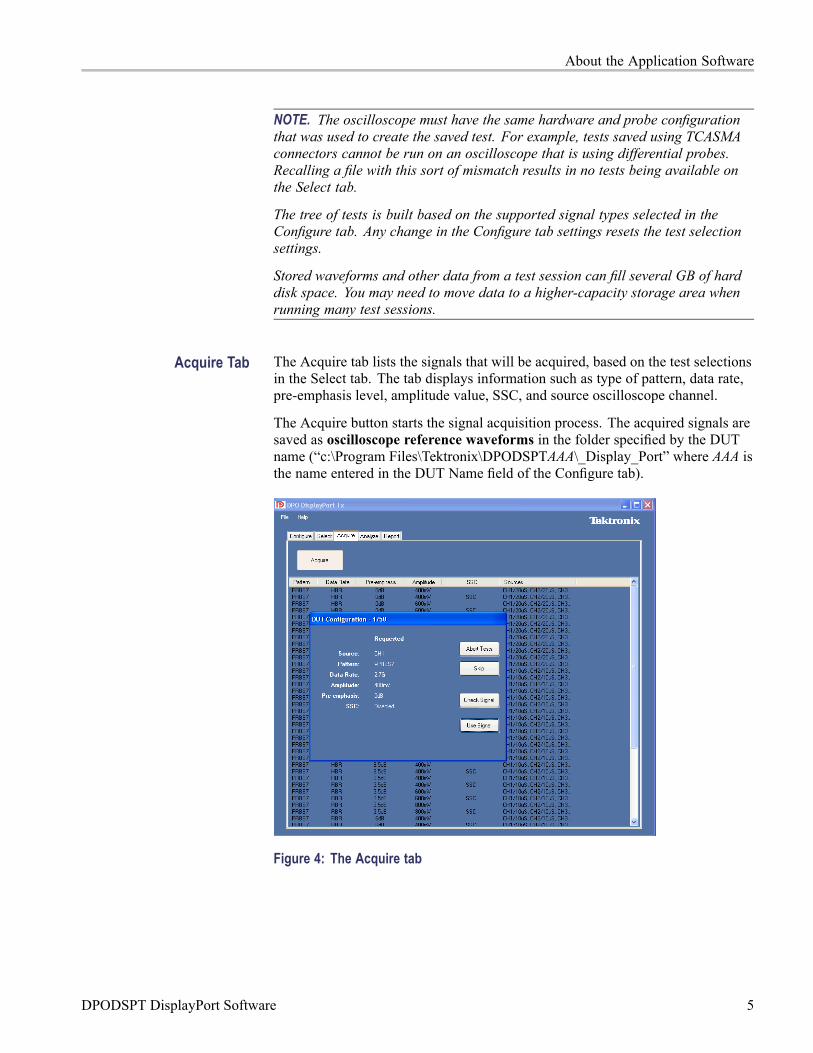
Acquire Tab The Acquire tab lists the signals that will be acquired, based on the test selectionsin the Select tab. The tab displays information such as type of pattern, data rate,pre-emphasis level, amplitude value, SSC, and source oscilloscope channel.
The Acquire button starts the signal acquisition process. The acquired signals aresaved as oscilloscope reference waveforms in the folder specified by the DUTname (“c:\Program Files\Tektronix\DPODSPTAAA\_Display_Port” where AAA isthe name entered in the DUT Name field of the Configure tab).
Figure 4: The Acquire tab
DPODSPT DisplayPort Software 5
About the Application Software
NOTE. Some of the signals can support multiple tests. The list of signalsto be acquired does not show duplication of signals when used for multiplemeasurements.
When you start the acquisition by clicking the Acquire button, a pop-up messagebox, as shown in figure 5, displays the signal being acquired. Attributes of thesignal to be acquired are displayed.
There are four buttons in the Acquire tab:
Abort Tests. Click this button to abort the entire test session. No acquisitiontakes place.
Skip. Click this button to stop acquiring the current signal and move (skip) to thenext signal type in the list. Measurements that depend on the skipped signal typewill not be performed.
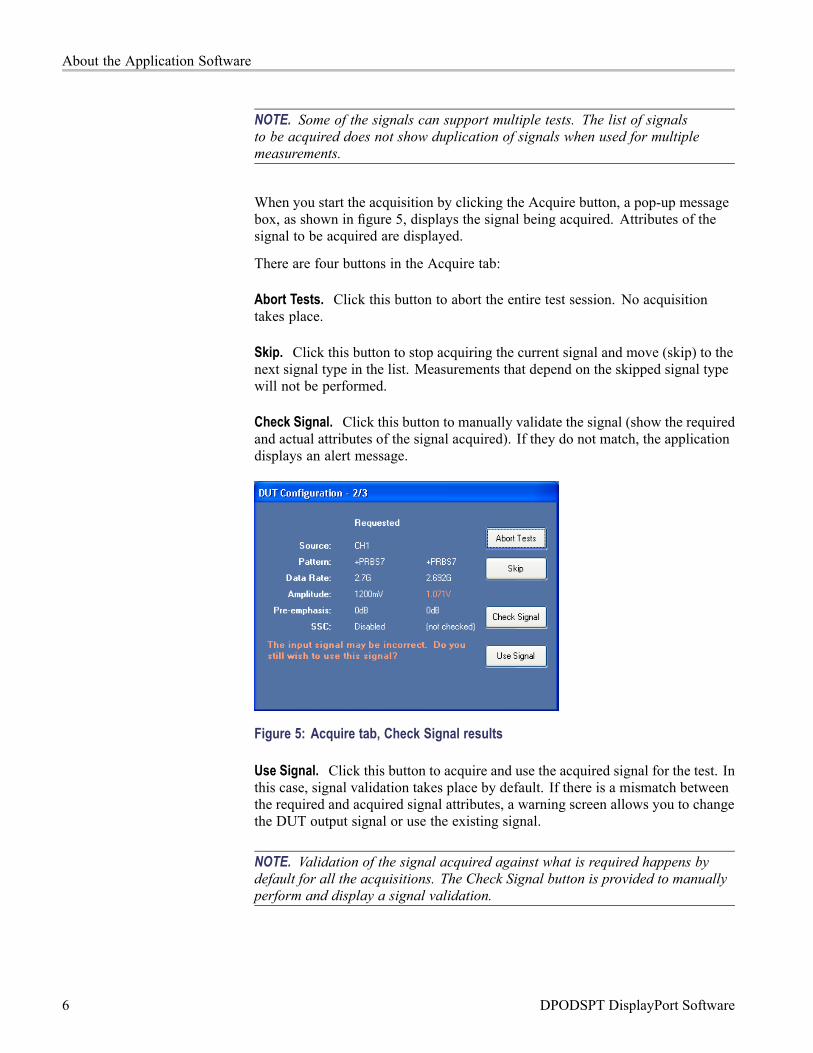
Check Signal. Click this button to manually validate the signal (show the requiredand actual attributes of the signal acquired). If they do not match, the applicationdisplays an alert message.
Figure 5: Acquire tab, Check Signal results
Use Signal. Click this button to acquire and use the acquired signal for the test. Inthis case, signal validation takes place by default. If there is a mismatch betweenthe required and acquired signal attributes, a warning screen allows you to changethe DUT output signal or use the existing signal.
NOTE. Validation of the signal acquired against what is required happens bydefault for all the acquisitions. The Check Signal button is provided to manuallyperform and display a signal validation.
6 DPODSPT DisplayPort Software
About the Application Software
Acquire Tab (if usingDP-AUX Control)
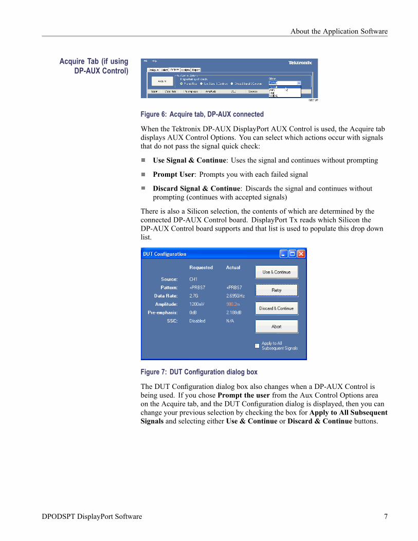
Figure 6: Acquire tab, DP-AUX connected
When the Tektronix DP-AUX DisplayPort AUX Control is used, the Acquire tabdisplays AUX Control Options. You can select which actions occur with signalsthat do not pass the signal quick check:
Use Signal & Continue: Uses the signal and continues without prompting
Prompt User: Prompts you with each failed signal
Discard Signal & Continue: Discards the signal and continues withoutprompting (continues with accepted signals)
There is also a Silicon selection, the contents of which are determined by theconnected DP-AUX Control board. DisplayPort Tx reads which Silicon theDP-AUX Control board supports and that list is used to populate this drop downlist.
Figure 7: DUT Configuration dialog box
The DUT Configuration dialog box also changes when a DP-AUX Control isbeing used. If you chose Prompt the user from the Aux Control Options areaon the Acquire tab, and the DUT Configuration dialog is displayed, then you canchange your previous selection by checking the box for Apply to All SubsequentSignals and selecting either Use & Continue or Discard & Continue buttons.
DPODSPT DisplayPort Software 7
About the Application Software
Acquire Tab (if usingpreviously-stored
waveforms)
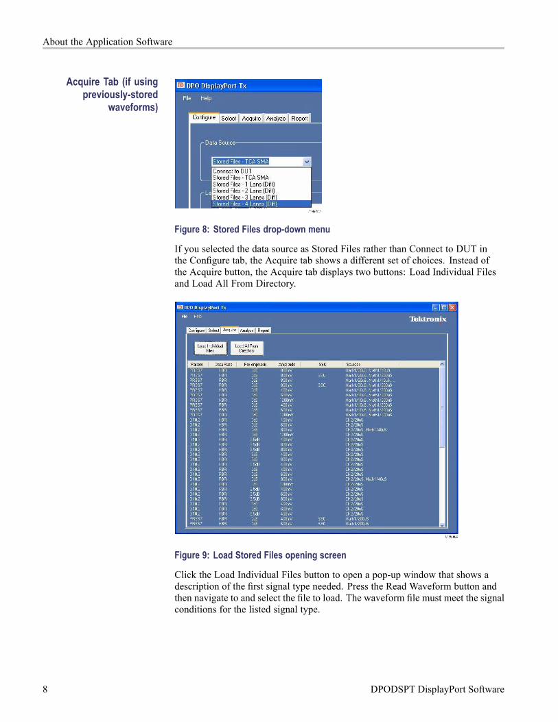
Figure 8: Stored Files drop-down menu
If you selected the data source as Stored Files rather than Connect to DUT inthe Configure tab, the Acquire tab shows a different set of choices. Instead ofthe Acquire button, the Acquire tab displays two buttons: Load Individual Filesand Load All From Directory.
Figure 9: Load Stored Files opening screen
Click the Load Individual Files button to open a pop-up window that shows adescription of the first signal type needed. Press the Read Waveform button andthen navigate to and select the file to load. The waveform file must meet the signalconditions for the listed signal type.
8 DPODSPT DisplayPort Software

About the Application Software
If you are loading waveform files that were automatically saved fromthe DPODSPT application, the file names indicate the signal type andsettings used to create that file. For example, a saved file could be namedPRBS7_HBR_400mV_0dB.wfm. If you manually name a file name for savedwaveform data, use a file naming convention that clearly describes all of thewaveform parameters.
Figure 10: Load Individual Files navigation screen
DPODSPT DisplayPort Software 9
About the Application Software
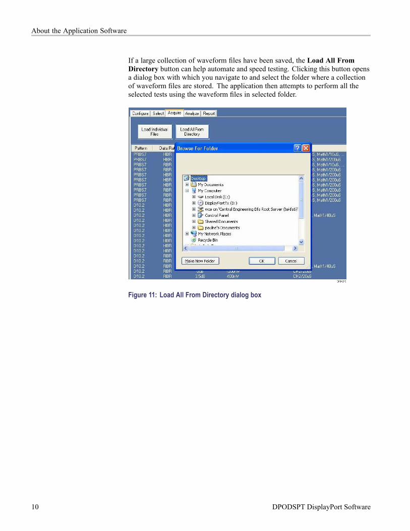
If a large collection of waveform files have been saved, the Load All FromDirectory button can help automate and speed testing. Clicking this button opensa dialog box with which you navigate to and select the folder where a collectionof waveform files are stored. The application then attempts to perform all theselected tests using the waveform files in selected folder.
Figure 11: Load All From Directory dialog box
10 DPODSPT DisplayPort Software
About the Application Software
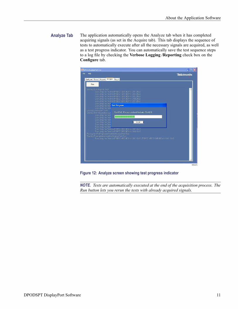
Analyze Tab The application automatically opens the Analyze tab when it has completedacquiring signals (as set in the Acquire tab). This tab displays the sequence oftests to automatically execute after all the necessary signals are acquired, as wellas a test progress indicator. You can automatically save the test sequence stepsto a log file by checking the Verbose Logging /Reporting check box on theConfigure tab.
Figure 12: Analyze screen showing test progress indicator
NOTE. Tests are automatically executed at the end of the acquisition process. TheRun button lets you rerun the tests with already acquired signals.
DPODSPT DisplayPort Software 11

About the Application Software
Report Tab The application automatically opens the Report tab when it has completed testingsignals in the Analyze tab. The Report tab displays the results of the testsexecuted. The report data is saved in the data file folder associated with this testsession, as both a PDF and .csv format file.
Figure 13: The Report tab.
The PDF report includes:
Date and time of the test session (from the system clock)
The version of the DPODSPT Software
The version of the Compliance test specification (CTS) to which this testsession conforms
Device / DUT name and User comments (as entered in the Select Tab)
Compliance test summary
Detailed test summary
Individual test results with necessary graphic(s) / plot(s)
12 DPODSPT DisplayPort Software
Compliance Testing
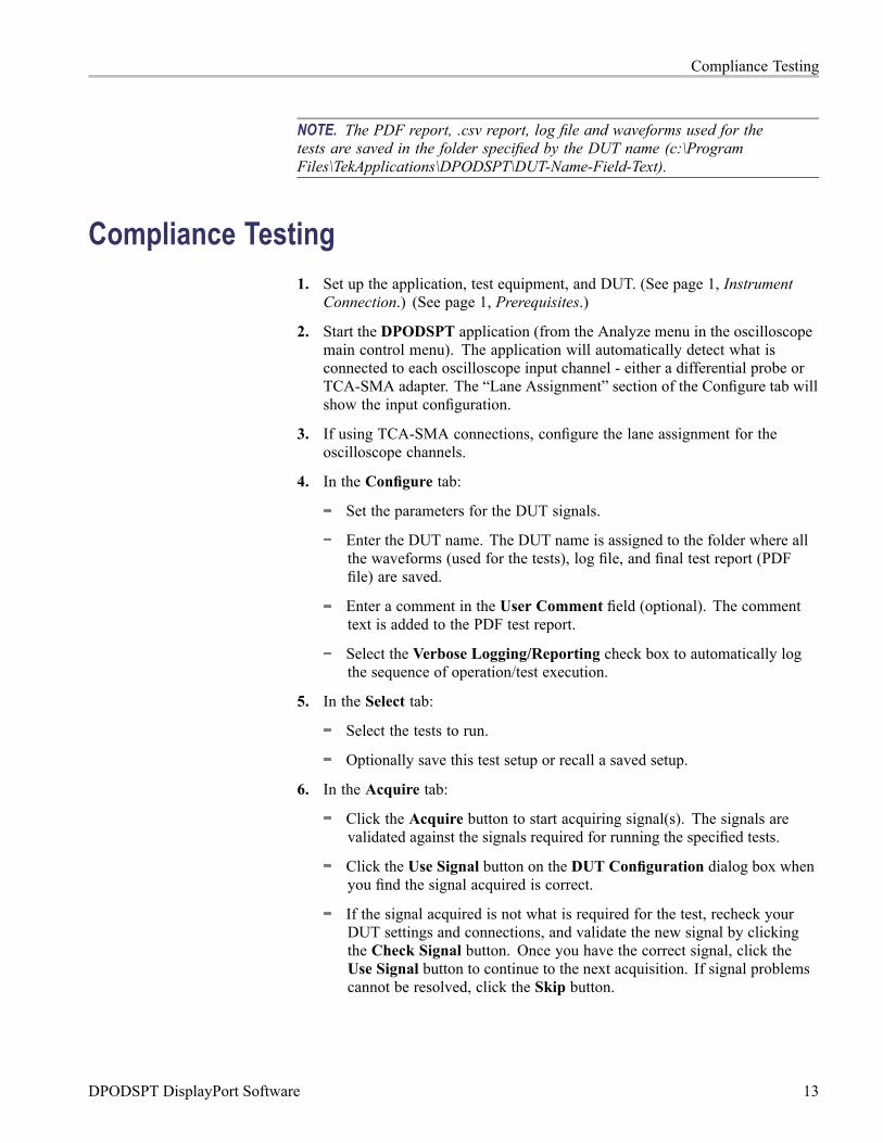
NOTE. The PDF report, .csv report, log file and waveforms used for thetests are saved in the folder specified by the DUT name (c:\ProgramFiles\TekApplications\DPODSPT\DUT-Name-Field-Text).
Compliance Testing1. Set up the application, test equipment, and DUT. (See page 1, Instrument
Connection.) (See page 1, Prerequisites.)
2. Start the DPODSPT application (from the Analyze menu in the oscilloscopemain control menu). The application will automatically detect what isconnected to each oscilloscope input channel - either a differential probe orTCA-SMA adapter. The “Lane Assignment” section of the Configure tab willshow the input configuration.
3. If using TCA-SMA connections, configure the lane assignment for theoscilloscope channels.
4. In the Configure tab:
Set the parameters for the DUT signals.
Enter the DUT name. The DUT name is assigned to the folder where allthe waveforms (used for the tests), log file, and final test report (PDFfile) are saved.
Enter a comment in the User Comment field (optional). The commenttext is added to the PDF test report.
Select the Verbose Logging/Reporting check box to automatically logthe sequence of operation/test execution.
5. In the Select tab:
Select the tests to run.
Optionally save this test setup or recall a saved setup.
6. In the Acquire tab:
Click the Acquire button to start acquiring signal(s). The signals arevalidated against the signals required for running the specified tests.
Click the Use Signal button on the DUT Configuration dialog box whenyou find the signal acquired is correct.
If the signal acquired is not what is required for the test, recheck yourDUT settings and connections, and validate the new signal by clickingthe Check Signal button. Once you have the correct signal, click theUse Signal button to continue to the next acquisition. If signal problemscannot be resolved, click the Skip button.
DPODSPT DisplayPort Software 13

Oscilloscope Probe or Cable Calibration
Keep changing the DUT settings and connections to acquire appropriatetest signals as prompted by the Acquisition Status dialog box.
If you are using the optional Tektronix DP-AUX Control device, specifywhat the software should do with "check signal" failures.
7. Once all the signals are acquired, the application will automatically startrunning the tests. If tests do not automatically start running, click the Runbutton in the Analyze tab. Test execution progress is shown in a statuswindow. Once the tests are executed, the report is shown in the Report tab.The waveforms and report are stored in the specified folder.
Oscilloscope Probe or Cable CalibrationBefore beginning any test or data acquisition, you must warm up the oscilloscope,run a signal path compensation (SPC) operation, and deskew the test cables orprobes you are using for the DUT test. Signal Path Compensation compensatesthe signal pathways for gain and offset errors. Cable deskew compensates fortiming differences between any two cables or probes. This section includes theprocedure for running a SPC and deskewing the cables/probes.
The DSA/DPO70000 series oscilloscope must be calibrated (SPC and deskew)manually after a minimum 20-minute warm-up period or whenever a newmeasurement session is going to begin.
These calibrations are not permanent. It is recommended that you perform asignal path compensation once a week and whenever the ambient temperature ofthe oscilloscope has changed by more than 5 °C. It is recommended that youperform a cable deskew before starting any new measurement session using theoscilloscope and cables.
Signal Path Compensation Use the following procedure to run the signal path compensation (SPC) utility:
1. Disconnect all input cables to the oscilloscope channels.
2. Install Tektronix TCA-SMA (or TCA-292MM) input adapters in all fourchannels, and make sure that nothing is connected to the SMA inputs. Theadapters prevent transient voltages from leaking into the input amplifiersand analog to digital converters that could adversely affect the quality ofthe calibration routine.
3. SelectUtilities > Instrument Calibration in the DPO/DSA70000 application.
4. Click the Calibrate button. It takes about 10 minutes to get the SPCcalibration result. The final status should be Pass.
14 DPODSPT DisplayPort Software
Oscilloscope Probe or Cable Calibration
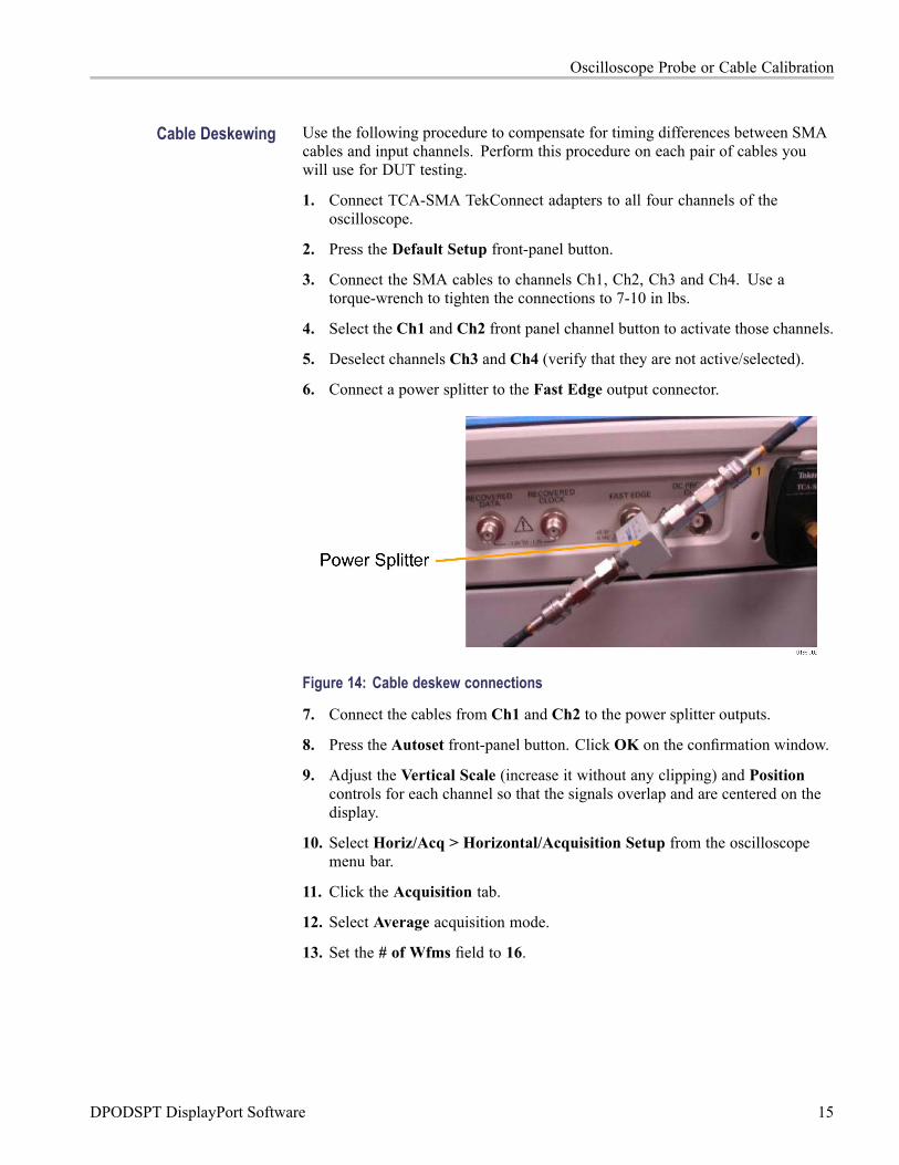
Cable Deskewing Use the following procedure to compensate for timing differences between SMAcables and input channels. Perform this procedure on each pair of cables youwill use for DUT testing.
1. Connect TCA-SMA TekConnect adapters to all four channels of theoscilloscope.
2. Press the Default Setup front-panel button.
3. Connect the SMA cables to channels Ch1, Ch2, Ch3 and Ch4. Use atorque-wrench to tighten the connections to 7-10 in lbs.
4. Select the Ch1 and Ch2 front panel channel button to activate those channels.
5. Deselect channels Ch3 and Ch4 (verify that they are not active/selected).
6. Connect a power splitter to the Fast Edge output connector.
Figure 14: Cable deskew connections
7. Connect the cables from Ch1 and Ch2 to the power splitter outputs.
8. Press the Autoset front-panel button. Click OK on the confirmation window.
9. Adjust the Vertical Scale (increase it without any clipping) and Positioncontrols for each channel so that the signals overlap and are centered on thedisplay.
10. Select Horiz/Acq > Horizontal/Acquisition Setup from the oscilloscopemenu bar.
11. Click the Acquisition tab.
12. Select Average acquisition mode.
13. Set the # of Wfms field to 16.
DPODSPT DisplayPort Software 15
Oscilloscope Probe or Cable Calibration
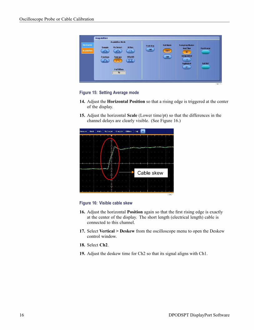
Figure 15: Setting Average mode
14. Adjust the Horizontal Position so that a rising edge is triggered at the centerof the display.
15. Adjust the horizontal Scale (Lower time/pt) so that the differences in thechannel delays are clearly visible. (See Figure 16.)
Figure 16: Visible cable skew
16. Adjust the horizontal Position again so that the first rising edge is exactlyat the center of the display. The short length (electrical length) cable isconnected to this channel.
17. Select Vertical > Deskew from the oscilloscope menu to open the Deskewcontrol window.
18. Select Ch2.
19. Adjust the deskew time for Ch2 so that its signal aligns with Ch1.
16 DPODSPT DisplayPort Software

Oscilloscope Probe or Cable Calibration
Figure 17: Cable skew adjusted
20. Remove the cable attached to Ch2 from the power splitter. Keep the otherend of the cable attached to the oscilloscope input.
21. Repeat steps 3 to 20, connecting the cable fromCh3 to the deskew attachment.Make sure to deselect Ch2 and select Ch3.
22. Repeat steps 3 to 20, connecting the cable fromCh4 to the deskew attachment.Make sure to deselect Ch3 and select Ch4.
23. The deskew procedure is complete when Ch2, Ch3, and Ch4 have all beendeskewed to Ch1. Take care to leave the cable and oscilloscope connectionsundisturbed for the duration of testing on the DisplayPort source device.
NOTE. If you are using differential probes instead of direct SMA cable connectionsto the oscilloscope, perform the procedure with the cables connected to the +input side of each probe.
DPODSPT DisplayPort Software 17