Downloaded from EizEiml · Aluminum Alloy 2024, Plate and Sheet ... Engineers, hsc.,400Commonweahh...
47
EizEiml MIL-F-87260(USAF) 7 Fe12rssnrv199 2 . 0 9 FOAM MATERIAL, EXPLOSION SUPPRESSION, INHERENTLY ELECTRICALLY CONDUCTIVE, FOR AIRCRAFI’ FUEL TANK AND DRY BAY AREAS This s~ificncion is approved for use by tie Depansnesstof the Air Force and is available for use by afl Dqsanments and Agencies of dre Dqssnmem of Defense. 1. SCOPE 1.1 Scope. This document covers thersquirements fornrselectricslly comluctiveopen-celled fasrss mrxerief titwill be usedforexplasion suppressiar in aimsft fuel tanks and &y bay areas (cavities). 12 Clnssitkntion. The conductive explusion suppression mnmrid (E.SM)shsfl be of the following classes nnd gmdes (see 6.6h Class 1- ESM to be @ forsinglepoint msdover-wing refueling throughout the tempemsure rnrrgeof 0to+160”F Grde IC - Cosrse pore Gmde HC - Fine pore Gmde IC - Come pore Gmde IIC - Fine pore AH Iyf!es of E-SMof both classes shall have a mmimd density of 1.3 IWCUft. 2. APPLICABLE DOCUhlENTS 2.1 Government documents 2.1.1 Specilicntion& stnsrdnrd.%md handbooks. The following specifications, stnndsrds, and hsrdbwks form a pan of tis document to the extent specified herein. Ursk.ssotherwise specified, the issues of Uscsedocoments sre drase Iisrcd in the issue of the Department of Defense Imlex of Specilicaion and Starrdmds (DODISS) and supplement therelm cited in the soliciteticar (see 6.2). Baseticisf commerrts (recommendations. sdditions, deleliorus) and any f!e.rdnmt &la which maybe of use in a~roving this daumenl should k uddrcs.sed10 ASDIENES, Wright-Patterson AFB, OH 45433-6503 by using the .%ndardkntion f30cunserrIImprovement Proposal (DD form 1426) appearing at the end of this document orbyletter. AMSC WA Fsc: 9330 DISTWBUTION STATEMENT A: Approved for pubfic releasa disuib.nion is unlimited. Downloaded from http://www.everyspec.com
Transcript of Downloaded from EizEiml · Aluminum Alloy 2024, Plate and Sheet ... Engineers, hsc.,400Commonweahh...
EizEimlMIL-F-87260(USAF)7 Fe12rssnrv1992
.
0
9
FOAM MATERIAL, EXPLOSION SUPPRESSION,
INHERENTLY ELECTRICALLY CONDUCTIVE,
FOR AIRCRAFI’ FUEL TANK AND DRY BAY AREAS
This s~ificncion is approved for use bytie Depansnesstof the Air Force and is available for use by afl
Dqsanments and Agencies of dre Dqssnmem of Defense.
1. SCOPE
1.1 Scope. This documentcoversthersquirementsfornrselectricsllycomluctiveopen-celledfasrssmrxerieftitwillbeusedforexplasionsuppressiar in aimsft fuel tanks and &y bay areas (cavities).
12 Clnssitkntion. The conductive explusion suppressionmnmrid (E.SM)shsfl be of the following classes nnd gmdes
(see 6.6h
Class 1- ESM to be @ forsinglepoint msdover-wing refueling throughout the tempemsure rnrrgeof 0to+160”F
Grde IC - Cosrse pore
Gmde HC - Fine pore
Gmde IC - Come pore
Gmde IIC - Fine pore
AH Iyf!es of E-SMof both classes shall have a mmimd density of 1.3 IWCUft.
2. APPLICABLE DOCUhlENTS
2.1 Government documents
2.1.1 Specilicntion& stnsrdnrd.%md handbooks. The following specifications, stnndsrds, and hsrdbwks form a pan
of tis document to the extent specified herein. Ursk.ssotherwise specified, the issues of Uscsedocoments sre drase Iisrcdin the issue of the Department of Defense Imlex of Specilicaion and Starrdmds (DODISS) and supplement therelm cited
in the soliciteticar (see 6.2).
Baseticisf commerrts (recommendations. sdditions, deleliorus) and any f!e.rdnmt &la which maybe of use ina~rovingthisdaumenlshould k uddrcs.sed10 ASDIENES, Wright-Patterson AFB, OH 45433-6503 byusing the .%ndardkntion f30cunserrIImprovement Proposal (DD form 1426) appearing at the end of thisdocumentorbyletter.
AMSC WA Fsc: 9330
DISTWBUTION STATEMENT A: Approved for pubfic releasa disuib.nion is unlimited.
Downloaded from http://www.everyspec.com
M1L-F-87260(USAF)
SPECIFICATIONS
Federal
A-A-208
L-P-378
QQ-A-250/4
QQ-A-250/12
QQ-P-35
l--s-735
PPP-B-636
Military
MIL-P-116
MIL-T-5624
MfL-1-276S6
MIL-B-83054
MIL-T-83I33
MIL-C-87936
STANDARDS
Federal
Fed. Test Method
Std. No. 101(Method 4046. I)
Military
MIL-STD-129
MIL-STD-83 I
Ink, Marking,S[encil,C@que (PoroussndNon-PorousSurfsces)
Plastic, Sheet and Strip, Thin Gauge, Polyoletin
Aluminum Alloy 2024, Plate and Sheet
Aluminum Alloy 7075, Plate and Sheet
Passivation Treatments for Corrosion-Resistant Steel
Stsndard Test Fluids, Hydrccmbon
Boxes, Shipping, Fiberboard
Preservali on, Methods of
Turbine Fuel, Aviation, Grade JP-4. JF-5, and JP-5/JJ-8 ST
Inhibitor, Icing, Fuel System
Baffle rmd hrerting Material, Aircraft Fuel Tank
Turbine Fuels, Aviation, Kerosene Types, NATO F-34 (JP-8) and NATO F-35
Cleaning Compounds, Aircrsft Exterior Surfaces, Water Dilutable
Test procedures for Packaging Materirk “Electrostatic Properties of Materials”
Marking for Shipment and Storage
Test Reports, Preparation of
MIL-STD-2073-I DoD Material Frccedures for Development srrdApplication of Psclmging Requirements
MIL-STD-2073-2 Packaging Requirement Codes
(Unless olherwise indicated, copies of federal and military specifications, standards, and tmndbooka sre available fromthe Stmuiardization Dccuments Order Desk, Building 4D, 7CKlRobbim Avenue, Philadelphia, PA 19111-5094.)
2.1.2 Other Government documents, drawings, and publications. The following other Government dccuments,drawings, and publications form a PM!of this document m the extent specified herein. Urdess otherwise specified, tJreissues are those cited in the solicitation. o
2
Downloaded from http://www.everyspec.com
MIL-F-87260(USAF)
o TEST REFORTS
Air Force Engineering and service Caner
ESC-TR-84-63 Effeztive Dkpossl of Fuel Cell Polyurdrmre Foam
(Copies of this repon sre nvsilsble from the Naiionrd Tdsnkxd Information Service (NT7C), 5285 Port Royal Rood.Springfield VA 22161.)
AIR FORCE TECHNICAL ORDER
T.O. 42B-1-I QmIity Control of Fuels and Lubsicencs
(Copies of Air FosceTechnimf orders are avsilable through yourcommcdng oflic.er from Oklslmma City Air Logistics
Center (OC-ALCYMMEDT), linker Air Force Base. OK 73145-5990.).
22 Non-gov.emment publications. The following documents form a PM of this document to dre extent smitiedherein. Lfnks ocherw’isespecified. the issues of thcdcmsmenls which are DOD edopled arcchcselistcd in the issue of theDODISS specified in thesolicitntion. Unless othecwisespecified, dse issues of dcaunems not listed in the DODISS are& issues cited in the solicitation (see 6.2).
American Society for Testing and Moterinls (ASTM)
D257-78 SIrmdsrd Test Mechcds for DC Resisource or Conductance of Insulating hinlerisls
o FI IIO-88 Slmdwd Test Mehd for Ssndwich Cor’rmion Test
D1655-89 Smndani Specification for Aviation Wine Fuek
D2276-89 Smndmd Test Methcds for Pocticulote Conmrsdmmt in Aviruion Thrbine Fuels
D3374-86 .Mnchrd Methods of Tesling Flexible Cellrrlnr Mocerink - Slab, Bonded, ond Molded
Urethane Fcmnss
Scciety of Automotive Engineers, Inc. (SAE)
AIR-4170 Re!icukrtecfPolyurethane Fosm Explosion Suppression Mnterisl for Fuel Systems andDV Bays
(Applicscion for copies of ASTM.Sshmdd be eddressed to tre Americsn SccieIy foresting md Maferisls, 1916 Race
Street, Phihxklphio.PA 19103. Application for copies of SAES should be addressed 10 the Seciet y of Automoti\{eEngineers, hsc.,400Commonweahh Drive, Wsrmncbde,PA 150)6. Copies not availoblein ticurmnt ASTM sradsrds
may be obuined fmm the procuring wlivily.)
(Non-Govemmcnt sousdmds and other publica!iom we ncmnnlly available from the organizations that prepare ordistribute thedccuncems. These dccume.ms also mnybeovnilablein orthroughlibrsries orotherinfoncrstionsl services.)
23 Order of precedence. In the eveni of a conflict bccweerrthe mxt of this document srxf the references cited herein(except for relakdnssocintedd etail spccilications. speciticotionsheets, or MSstondsrd.s), Ihetext of this dccmnent u&es
● precedcnm%Nothing in rhis dccumem. however, supersedes applicable Inws msdreguladons urdcss o specific esemptionhm km obtained,
3
Downloaded from http://www.everyspec.com
MIL-F-87260(USAF)
3. REQUIREMENTS
3.1 Qualification. Material furnished under this specification shall lx a preduct which is authorized by the qualifying ●activity for listing on the applicable qualified products list at the time of award of contract (see 4,4 and 6.4).
3.1.1 RequaMcation. Before any change is made in the quality, composition, sotuce of ingredients, or source of supplyof the final product, the manufacturer must contact the qualifying activity to determine if requalification or partialrequalification is required (see 6.4.1).
3.2 Matarkils.‘he raw materials used in processing the material shall be of the highest quality rmd standards forcommercially available products of this type and shall be of the same formulation as that used in the qualification testsample. The end product shall be a flexible urethane foam which is suitable for use in aircraft fuel tanks. ‘flref inalproductshall be a materki which is inherendy eleztricaly conductive.
3.2.1 Product toxicologkal data and dMpoaal. Product toxicological data relating to the kit promsing and end use, -particularly by hot wire thermal decomposition, shall be submitted in the qualification test report for review by an
appropriate military medicaJ authority who will determine if any use restrictions esist relative to the safety of personnel.fn addition, avtilable data relating to possible methods of disposal for the foam material shall be provided. This includes “
both new material and materiaJ that has been exposed to fuel in an aircraft fuel tank For additional guidelines on thedisposal of fuel cell reticulated foams, consult ESC-TR-84-63.
3.2.2 Human exposure toxicology. The material shall not pose a toxicity hazard to persomel who come in contact withthe product. Toxicological data substantiating itasafety shall be provided along with the conductive material compositionfor review by military medical authority to verify per’somel safety. All propriety information shall be protected fromdisclosure in accordance with appropriate Federal regulations.
3.2.3 Tracer elements. A tracer element shall be incorporated into the material for identification puqmses. The tracerelement shsll be submitted to the qualifying activity for approval end shall be unique to each vendor. The manufacturershall also supply the analytical test procedure which can be used to identify the tracer element. ●3.2.4 Manufacturer internalspacitk.ation and production quality control documents. ITre conductive materialmanufacturer shall provide adequate internal dccumenta (specificationdnmmmls) to define rmdcontrol the production,testing, and quality control of the material. This qualification documentation shall include, es a minimum, themanufacturer’s quality control memualand intemrd specification which dascrih such items as: manufacturer’s product,prcduct part numbers, available bun sizes, production testing rmdfrequency of the production teats, tasting requirements(limits), quality control prwxrlures, and any other information relative to the materials’ certification or usage. llrisdocument(s) shrdlbe made available foruseby the DCASMAperaormel during production facilb y inspections and during
material pr.xurement certification, The vendor’s quality control document(s) should also be referenced in the productqualification repal and a copy provided to the qualifying agency as part of the qualification package.
3.3 Age. lle maximum time of delivery from the manufacturer shall not exceed one year. If the time since manufamue
exceeds six months, the material shall be visually ina~cted, and there shall be no evidence of discoloration resulting insurface deterioration which results in a loss of tcnsion properties. Discoloration of urethane foams with age and exposureto ultraviolet light is a normal occurrence and does not necessarily indicate deterioration,
3.3.1 Storage life. ‘Ile storage life of the materd covered by this specification isnot limited, provided it is maintained in
the original sealed polyethylene bag plus opaque overwrap at temperature Mow 90°F. Storage should be in an area outof direct sunlight and outside weather, including high humidit y and temperature, The material should be inspected forevidence of dkcoloration m surface deterioration (1OSSin tensile properties) prior to use.
3.4 Coloring pigments. Coloring pigments or coatings shall not be resdly extractable when the conductive material isused in contact with fuels conforming to ML-T-5624, MfL-T-83 133, and ASTM D- 1655. Product color is not limited
except that it shall not be blue, orange, yellow, or red. ●4
Downloaded from http://www.everyspec.com
MIL-F-87260(USAF)
3-5 Marker legibility. The rcmmcfrrcturershall identify o suimb[e marker for use on dte conductive mocerial kiI pieres
(individual idencificmion number’s)to be instslled in thenircmft fuel system. The morker shall be compatible with bothfuel rrndtheconductive msteritd. A possible source fern ficelcompntiblemnrking ink is A-A-208. A suggested marking
pm is avsiiable from the D@aph Corporation, Hernn, Illinois. The icfen!ificotion for a white opaque pigment (volve
nction msrker) is GP-X.
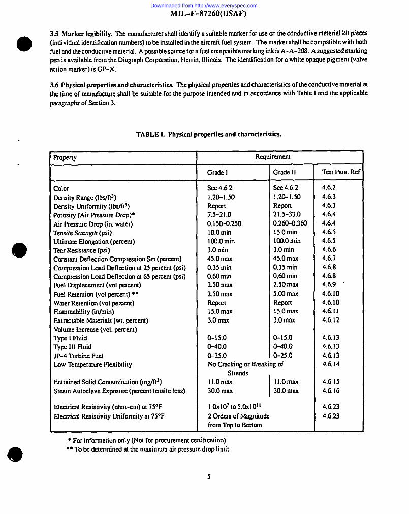
3.6 Pfcysicnfpcupec’tics cuedchnmcteristics. I?u @ysicnl properties and Chmacleristics of tie conductive mo!erid at
the lime of mmcufacture shafl te suitable for the purpose intended I@ in mordance wiIh Table I emd tie applicableparagraphs of .%ctimr 3.
TABLE L Physical properties and chnmcteristics.
property Requirement
Grade 1 Gmdc 11 TecI Pam. Ref.
Color See 4.6.2 See 4.6.2 4.6.2
Density Range (lbs/ftJ) 1.20-1.50 1.20-1.50 4.6.3
Density Uniformity (Ibdfl’) Refson Repmc 4.6.3
Porosity (Air Pressure Drop)* 7.s-2 1.0 21.5-33.0 4.6.4
Air Pressure Dcop (in. weter) 0.150-0.250 0.260-O.3d3 4.6,4
Tensile SIrengffr (psi) 10.0 min I5.0 min 4.6.5
Ultimote Elongation (percent) lm.omin [email protected] 4.6.5
Tear Resistance (psi) 3.0 min 3.0 tin 4.6,6
Constant Deflection Compression Set (percent) 45.0 mns 45.0 mas 4.6.7
Compression H Deflection at 23 percent (psi) 0.35 min 0.35 min 4.6,8
Compression bad Deflection at 65 percent (pal) 0.60 min 0.60 min 4.6.8
Fuel Disphcemcnt (VOIpercent) 2.50 mm 2.50 mos 4.6.9
Fuel Recemion (VOIpercent)”* 2.S0 mnx 5.CKrmns 4.6.10
Wscer Retemim (VOIpement) Repcm RepaI 4.6.10
Flammability (inhnin) 15.Omns 15.Omax 4.6.11
Extmctable Macerio.ls(wI. wrcenl) 3.0 mm 3.0 max. 4.6.12
Volume Increme (vol. pemem)T~ I Fluid 0-15.0 0-15.0 4.6,13
~ 111Ftuid 0-40.0 0-40.0 4.6.13
JP-4 lhrbinc Fuel 0-2s.0 0-23.0 4.6.13law Temperonue Flexibility No Crockiqq or Breaking of 4.6,14
StmndsEntrained Solid Cmrte.nsinmion(mg/ft3) 11.Omox 11.Omns 4.6,15
Steam Autoclave Expmsure (pescem tensile loss) 30.0 msx 30,0 mas 4.6.16
Electrical Re-sistiviIy(ohm-cm) m 75°F 10xIo710s.oxIoll 4.6.23
EJecu’hd Resistivity Unifomsily m 75°F 2 Ordm of Mngnitude 4.6.23
from Top to Balom
● For infoncsatiun only (NoI for praurement ceniticntion)● * To& ~t~~ m h muimmn tir pressure drop hsrit
5
Downloaded from http://www.everyspec.com
MtL-F-87260(USAF)
3.7 Performance requirements. The conductive material shall meet the following performance requirements (in
addition to Table1): ●3.7.1 Fuel immersion. The following fuel immersion requirements shall be met:
a. JI-4 immersion at 16Q”F. Thematerial shall not undergo more Uam 40,0 percemt loss in “d~-to-d@’ and“wet-to-wet” tension properties after 4,8, and 12weeks exposure. bI addition, the dry electrical resistivity property ofthe malericdafter fluid exposure shall not rise above 5,0x 10¹²ohm-cm after exposures of 4,8, and 12 weeks.
b. Wet property assessment at 75”F. The material shall not undergo more than 60.0 percent loss in tension,compression load deflection, and tear resishmce properties from @-t&wet after a 4-week exposure to JP-4 fuel.
3.7.2 Hydrolytic stability. The conductive material shall mecl the following hydrolytic stability requirements
a. Humidity exposure at 20Q”Fi’35percent relative humidit y. ‘I%ematerial shaJl not undergo more than 65 percentloss in tensile strength after 6 weeks exposure. ‘fhe electrical resistivity property of the material after exposure for 6 and .
10 weeks shall not exceed 5.OX1012ohm-cm.
b. WaterimmersionatI@“F.Thematerialshall not undergo more than 40.0 percent loss in tensile strength after 12weeks of exposur?
c. Dry bay-dry heat tests at 2SO”F.The material shall not undergo more than 65 Pwcent loss in tensile strength afterfour weeka of exposure. The electrical resistivity property of the material shall also be reported on a minimum weeklybaais for the duration of exposure and shall not exceed 5.OX10fi2ohn-cm after four weeks exposure.
3.7.3 Explosion suppression and flame arrestor characteristics. The conductive materiaJs shall meet the followingminimum requirements: ●
a. Coarse pore material. The coarse pore material shall suppress the combustion overpressure for a single voidignition of 20.0 volume percent to a value equal to or below 15.0 psid (pounds per square inch different id).
b. Fine pore material. The fine pore ms.terid shall suppress the combustion overpressure for a single void ignition of35.0 penx!nt volume [o a value equal to or below 15.0 psid. [n addition, the fine pore material shall prevent flamepropagation for the following conditions:
(1) AtOpsig initial prcasure and a combustion volume of 16,7percent volume, the required material WlcknessshaJl be 3,0 inches or less.
(2) At 3.Opsig initial pressure and acombuation volume of 16.7percent volume, the required material ti,ckzmssshall be 5,0 inches or less.
3.7.4 Corrosion and adbcsicm. The conductive material shall neither adhere to nor cause any pitting, erosion, orcorrosion to ahrmirmm alloy plates when in contact for 14days.
3.7.5 Ekctrical raistivity permanence. The conductive material’s electrical resistivity propeny shall not rise above5.OX1012ohm-cm after expcsure to the following conditions:
Water immersion at 120 ~5°F for four weeka. Water immersion at 160 *5°F for thr= weeks maybe substituted
3.7.6 Fuel compatibility. Properties of the JP-4 md JP-8 fuels exposed m the conductive ma@riaJ shall meet thefollowing requirements listed in MLL-T-5624:
a. Color shall be equal to or greater than 15.0 saybolt color units. ●6
Downloaded from http://www.everyspec.com

MIL-F-87260(USAF)
b. Existent gmrr shall not exceed 14.0 mg/lCx3rrrl.
●c. Portictdates shall no: esceed l.0 mgffiter.
d. Filtratimr time shall no! esceed 10.0 minutes.
e. Total acid number shsll na exceed 0.015 mg/KOH/g.
f. JF3WTAP (260) shall not exceed 25.0 mm Hg.
g. No visible extmtion of macerinl coloring pigment.
3.7.7 Eleetrirzd resistivity md electrostatic fuel impingement test. The elecoicsl resistivity srrd electrostaticcompwibility Cfrsrscttislics of the conductive mmerird shall meet the following rquiremenls:
. a. The dry electricsd resislivity of both classm of cotiuctive mmerial shsll be between 1.0s 107 srrd Mlx 1011
ohm-cm wherstestedac75 *YFsarJ 10,S0,9S*5~a!mlnti vehufidtim. hrarklitiorrtheelectricrd resistivityshall be
measured and reported for the following temperatures: 160,32,0,-20,-30,-40 fYF.
b. C3ass I Msminfs. The Claw I conductive materials shsll not produce m incendiary vapor ignition, electricaldischarges, or excessive static charge build-up (elecoicrd activit y) wherr impinged by JP-4 fiel h has a conductivityless thsrr 10conductivityy units (cu) 8s well m icrthe range from 103 to S00 cu. while in the rsnge of tempemhcms from
16CPFdown to O“F. The rsrrge of corrsfuctivity shsil Ee schieved through the use of fuel sys!em conductivity additives
defined in MfL-T-5624.
c. Class II Msierials. The Claw 11corrdrcctivematerials shall not produce as irrcersdisryvapor ignhims, elecoicsJ
discfmcge$ m excessive static chsrge build-up (electrical sctivi!y) when impinged by JP-4 fiel tit has a ccmductivity
e
less thmt IOCUm well rrsin the mnge from IW to SOOcrr,while in the rmrge of temperatures from lWFdown to -3tYF.
The range of conductivity shall be achieved through the use of fuel system conductivity ruiditives defused inMIL-T-5624.
3.78 Infmred spectrum analysis. Infmred specwurrrdata drsfl Lwprovided for the conductive mamrisl srsda.refemrrccstsndord polyether foam.
3.7.9 Static chnrge dmifsation test. Tire conductive maeeriol(s)stroll k evaluated 10detemrirre the lime it ties for en
irrducedelectmststiccharge to bedissipsted at vsrious Iempersnns including tie following: ~, 32,0,-20,-30, and -40
i5”F. The results. along with the materiel’s electrical rcsistivity, shall bused 10tiermicre if arradequate mte of powerdissipsdonccusbe achieved. Thetempemture at which the mteof Power dissipadondmslicdl ydropsoff arsdappmaches azero rste icragmphical plot of the dcuashsll bedetirud as thedissipatimr temperature limit (OTL), Ilris OTL shall be used
as the criteria for determining if the ms.!erialsatisfies the specification requirements for clsss 1 (Oe)or clsss 2 (-3tYFlrcrmerisds. Esmrrple dom plots m well ss fomruhm for calculating the power dissipation from the dis.siptiimr lime srrdelectrical resistivity sm provided in attachmem 3 for reference. ‘llrese lest data and results maybe substituted for theelectrostatic compscibility test dsta in 3.7.7.
3.7.10 Electrochemical corrusiorr. llre conductive material shall neither adhere to nor cmoe any pireirrg,emsimr, ordiscolorstiorrof metal plates. In sddition, the rrmmrialshall not produce aacrrem flow grsatertharr that for bluepcdyetlrerfosrrrproduced irroccordarrce with MIL-B-83034.
3.7.11 Aircmft service test. ‘fire service ce.skd materials critical pmperdes shsll not degmde below the minimumspecification reqrrirements. Tire electrical resisrivity shsfl not increase by more thsrr two orders of msgrsihr& from theorigiml baseline vrdues nor shall it exceed 3X10[2ohm-cm. There shall be no evidence of elecmicd builduu. dischsme.
e vwr ig~tia. or sfflgeh (b~w) of~efoamduringtheseticetestevaluations.
7
Downloaded from http://www.everyspec.com
MIL-F-87260(USAF)
3.7.12 Manufacturing demonstration details. ‘he manufachuer shall successful] y demonstrate that the material canbe fabricated in the various standard bun sizes defined in 3.8. Hot wire is acceptable for use in frml fabrication trimmingof the materials provided it does not discolor the bun surfaces non-uniformly. ●3.8 Dimensions and tolerances. Material shall be produced in the following standard size buns:
Gradel -40inches x80inches x8inches:44inches x 110inchesx8inchea;44inchas x 110inchea x 12inches:and44inches x 110 inches x 4 inches.
Grade II -44 inches x 110inches x 8 inches: 44 inches x 110inches x 12inchex and 44 inches x i 10inches x4 inches
3.8.1 Optional bun sizes. OptionaJ bun sizes of the material may also be prcduced by the manufacturer provided thefollowing sizes are offered: 44 inches x 110inches x 12inches fortheGrade IC md40 inches x 80 inches x 8 inches for IheGrade IIC. Manufacturing tolerance limits on bun sizes shall be as follows unless otherwise agreed to by [he procuring .activiiy and manufacture
a. Widlh +1. -O inch
b. Length +1, -O inch
c. Height +1/8, -1/8 inch
3.9 Final product identification. On the end of each bun, a durable label card shall be attached using Detison 3-inchloop style Swiftachment fasteners, P/N08909 (Dennison, Fasteners Division, 888 Seventh Avenue, 13th Floor, NewYork. NY, 10019) or equivalent. The label card shall clearly identify the manufacturer’s part number, date ofmanufacture, manufachrer’s run number, lot numhr, and bun number. Where applicable, the government contract or
order number shall be included. here shall be nocolorcwJing or marking on the outer surface of the bun. Each bun shallbe sealed in aclean4-mil black polyeth ylenebag, per L-P-378 Type I, Class 1,Grade B, as it comes off the manufacturing
line. ●3,10 Workmanship. The material shall be fabricated in accordance with high grade manufacturing practices coveringthis type of material. ‘he material shall be suitable for its intended use and free of defects which may affect itsperformance. It shall be of uniform color and electrical resistivit y and free from excessive voids. It shall not be corrosiveor deleterious to fuel systems, metals, and elastomers. Hotwire cutting maybe used for the final finishing of the buns tominimize contamination.
4. QUALITY ASSURANCE PROVISIONS
4.1 Responsibility for inspection. Unless otherwise specified in the contract orpurchase order, the vendor is responsible
fortiepetiommce ofallinspction mquirementa (exminations mdtests) mspwifidherein. Except asotAerwise
specified in the contractor purchase order, the vendor may uaehis own or any other facilities suitable for the performanceoftileimp~tion rquiremenk specified herein, ti~stisapprov& bythe Government. The Government reserves theright to perform any of the inspections or tests set forth in this s~cific ation where such inspections are deemed necessaryto ensure supplies and services conform to prescribed requirements.
4,1.1 R~ponsibilily forcompUance. Allitenlsshall nleetall rqui~menhofsmtions 3md5. ~ehspectionsetfofiintilss~cification skllb~ome aptioftie contractor' soverdl inspection system orqudityprogrm. Theabsenceof
any inspection requiremen~ in the specification shall not relieve the manufacturer of theresponsibilit y of ensuring that allproducts or supplies submitted to the Government for acceptance compl ywith all requirements of the contract. Samplinginspection. as psrt of manufacmring oWrations, is an acceptable practice toaacertain conformance to requirements,
however, this does not authorize submission of known defective material, either indicated or actual, nor does it committhe Government to accept defective material. ●
8
Downloaded from http://www.everyspec.com
II
;04.2
MIL-F-87260(USAF)
Clossificnlion of tests. The irrspcctimr requimmems specified herein ore classified as follows:
a. Qurdificmion tests (4.4)
b. Qunlity confonnmceinspection(4.5)
4.3Testconditions
43.1 Tempcroture and hrmridity. Unless otherwi= spcilied herein. all !ests shsll be conducted msdec knownconditions OftetCCfSeIUNISsnd relative humidity. Prior 10physicnl pmpeccytesting, s~imenc shnJlbe pcecondhicuredin
the test earvimrrrcrcmn minimum of 30minutes.
1“
43.2 Test fluids. Unless otherwise specified herein, the test fluids strsll be of known properdes snd certified in
occorclancewith the referenced militsry spcciticmion. The turbine fuds ccurformingto MfL-T-5624 and MIL-T-83 133mnybeobtained from the qualifying octivi!ysdong with ocenified mst rep-m detiing, os a minimum, the specific gmvily,distilloticm, aconrmic comesu, existeru gum. sulfur ccmk.m, Reid vapor pressure (JP-4 fuel only), fuel system icinginhibitor level in accorcbmce with MIL-1-276S6, ond fuel electrical conductivity level.
4.33 Bnsic psopcrty testing. Lhde-sse+herwisespecified herein, all bnsic property tests sfrsfl be in sscordsncewith the
qsplicsble sections specified in ASTM D3574. In thecme where more than one specimen is @Ied, the ovemge shall be
determined. However. 011volues shall be reported for afl but production resting. Unless mhecwise specified. all samplespecimens shsdl be Icsted in the dry condiion. [n the case where fuel-wet testing is required (special tension. mmresismnce. and compression load deflection tests) the specimen should be removed fmm the Iesl fluid imnredhnel y prior
to pmpeny testing. &sined of escess fuel, snd Umntested.
43.4Specimencutting.Unlessotherwise s~ified herein, ICSIspmimen cmtingstmfl lx by die. snwcrming, or hot wire
o cutting.
4.4 Qmdificntion tssting. See 6.4.
4.4.1 Test scrcrsple(s). The specific bun(s) of mmerisl chow for the qualification tests shall b tYPi@f Of ful~
prcductionbuns in terms of density and porcsily (air pre.ssuredmp). Unless odserwisespxitied herein, dris bun shall bcselected from nezuthe midmoge in tdlowoble pormity propcnies. Additional qutrmities of msterird will be required st the
uwr @ lower Mess of the pososity rmge for fluid retention, esplmion suppression and flssne arrestor testing.
4.4.1.1 Test specimens
4.4.1.1.1 TCSIsection location. All [s.s!specimens shnfl be prepared fmm production mncerisl within the IeSIsection
Iccoiicmsspecified herein
4.4.1.1.1.1Qcmfifkntionand process control tests. For quditicntion mrdprocess cmtrol tests, the test section shsllconsist of nfull-sire bun which has been sectioned to provide for all thequnlificolicm test samples mrdtesl specimens. Allqualification test specimens used shrill be from the same machine cmrof production mmerinl and from the specified sre.$defined under 4.6. Where pmcticoble, the material rrsedsIMJIbe representative of chemid mnge in sfcnsiiymsdpore size(air pressure shop) for the given producl.
4.4.1.1.1.2Forpmduclionmd lot testing. For production and lot testing, the [ss1section shnfl consist of a sectionnpproximatel y 15 inclw..slong by the noneml bun height rusd width which hm Isesmprocessed afong with normalproduction mmecia]orwckenfmm nprrxhrctionbms. Locstionof the specific tesI ssmspleswithin the test seztionshdl be in
accordance with thegrride!iness~ifred undeI 4.6. S~imen measurements shell be in accordance with ASf?vf D3574.
4.4.1.1.2Qunntityofspecimens. Unless otherwise specified herein, time qx?cimens per sample shsll be testei llre
9
vslue ceporwclshsll be the svemge of those otsserved. 1fmsyvshre devistes more LIson20.0 percent from the average vohre,two Sdditiond specimens shall be tested Md the wemge for all five values dmfl be refmcted.
9
Downloaded from http://www.everyspec.com
MIL-F-87260(USAF)
4.4.2 Tut repo~ d~position of test specimens, and data for the qu~lfying activities. ‘he following shall be
timdshed to the qualifying activities as a qualification package:
a. Test report. A qualification test report shall be prepared in accordance with MfL-STD-83 1and shall include, as a ●minimum, the following:
(1) A tabulation of all qualification test data, including production test data on the qualification foam nm. All
values obtained shall be included as well as sample calculations.
(2) Detailed discussion of any failures, end retesting data
b. Disposition of test specimens. All test specimemsused in thequslification tests shell resubmitted tothequslifyingactivity (see 6.4. 1), except those subjected to the following tests:
Tension tests (4.6.5)
Tear resistance test (4.6.6)
Flammability test (4.6.1 1)
Steam autcclave exposure test (4.6.16)
hfrsred spectmm analysis test (4.6.25)
c. Testmaterial In addition, the following material shall be submitted to the qualifying activity:
(1) A sample from the qualification test bun(s) or sd@cnt bun: Size 20 inches x 20 inches x the bun thickness
(2) Unused retention samples (6 inches x 6 inches x 6 inches) near the bottom, middle, and top of the porosity
range and corresponding porosity (air pressure drop) specimem which have been sir pressure drop tested. ●(3) Sufficient material (approximately fou buns of Grade IC or two buns of Grade ffC) for the flame arrestor
tests s~citkd in 4.6.19.
(4)Corrosionendadhesionmetaltestspecimens(see4.6.20)
d. Other data. ‘the manufashuershakl include, as apart of the report, any information defined in 6.4 that may not havebeen available at the time of the submittal of the letter of request for testing, Also, any applicable data or informationwhich may relate to the qualification testing or future prcauements of the materiel shall be included. informationreferenced in 3.2,1,3.2,2, 3.2.3,3.2.4, and 3.5 shall also be included in the qualification test report.
4.4.3Qualification approvaf. Qualification test reports shell be signed or approved by a responsible representative ofh manufacturer,
4.4.4 Qualification tests. The qusMication tests shall consist of all applicable tests described under 4.6.
4..5Quafityconformance inspections. Quahty conformance inspections shall consist of the following tests:
a. Production tests (4,5.1)
b. fat tests (4.5.2)
c. Process control tests (4.5.3)
d. Examination of product (4.6.1)
10
Downloaded from http://www.everyspec.com
MIL-F-87260(USAF)
1.
4.S.1 Production tssts. Production tests shall be conducted on each run of material (see 6.4.1) prcukecl in accordancewith k following schechde:
a. All fumishal buns of mtuerid shall be visunlly inspected for examination of product per 4.6.1.
b. For every ISOfeet of production (or 15buns), the following tests shall be conduc[u! once on all producis:
Color bxt (4.6.2)
Density test (4.6.3)
Porosity (air pressure drop) test (4.6.4)
Tensile strengsh and elongation [csls (4.6.5)
Entrained solidcomsmicmtionrests(4.6.15)
%ass oulalove exposure kst (4.6.16) (See NOTE below)
Electrical resiscivity (4.6.23)
NOTE ‘flsesteam aumclavee.xpmure test specified in4.6,16 shell beconchrcted ordy once for each machine nm to verifythe hydrcdytic stabilitychamcm.ristics of the material. If the bun IMckness is Iessthmseight inches.then theentrainedsolidcontamination IeSIspecimen should be stacked (o get on eight-inch thickness.
4&2 LotIcsts.fnodcfitism10the production tests specified in 4.5.I.thecompressimIotideflection test specified in4.6.8 and the fuel retention test specified in 4.6.10. I shall be conducted on each lot (see 6.6.5) or six-month interval,whichever acurs firsI. The resuks shall be nminmined on file for s%turereference
43.2.1RejectionmsdmtesLFailureofanyofthetests~imens to conform 10he applicable requirements of 3.7 sndTable I shall requiren retest of the property which failed onmsndditional set of test specimens from tie same test section or
from lhe top of the odjuent bun. Additiond testing will k Oudrorizedby tie qualifying activit y in order 10isolste lheeslecctofdefective mnterinl. [n h everstoffailure of my of the reIested specimens, the material represented by thosespecimens shall be rejected.
4S3 Process ccmtmltests.fnsdditiontotheproductionondlottws,thefollowingtesssshellbeconducted on
production material at 12-month intervals, and the results nmintninsd on file for future reference:
a.Tea resiswsce test (4.6.6)
b.f%mmability IeSI(4.6. 1I)
c. Volume swell in JP-5 (4.6. 13)
d. Fluid immersion (wet property tests) (4.6.17.3)
e. Ekcsricnl rssislitity permanence (4.6.2 I)
4.S3.1 Rejcetion and test. Failure of any of the test specimens toccmform to the prmess control rquiremems spcitiedherein shsll require arecest of one nddhiorml seIof test s~imens forrhe property ths! fniled from thesmne IeSIsmtion, In
I M event of failure of my of the retested specimens, production shall bs hohed nnd no additiond mnterisl scceptcd until
othe reason for fnihue ha ken determined smt corrective action taken. l%equnlifying nctivityshafl renotified of my sestfsikres erscolmtersd.
11
Downloaded from http://www.everyspec.com
MIL-F-87260(USAF)
4.6 Test methods
4.6.1 Examination of product. Each finished burrof material shall be visuall y inspected forconsistenc y of cell structure, ●color, complete reticulation, obvious voids, or surface imperfections and the dimensional tolerances specifkl in 3.8 priorto final packaging. Criteria for rejection of buns shall be any exterior surface defects that could seriously affect the endfunction of the product, such aa:
a. Excessive cleaves, voids, or splits
b. Holeslarger than 1i2 inch in diameter and li2 inch in depth, not to exceed four per bun and no closer together than
two feet.
c. Level of non-reticulation not to exceed 0.40 percent of the total surface area or 0.07 percent of the total volume,baaed on the standard size bum
4.6.2 Color tsat. Testing for color shall be by visual analysis. The material shall be of a uniform color. Any unusual colorvariations over the foam surface shall be cause for rejection, especially distinct surface darkening due to dirt,
contamination, or surface deterioration ormry color mottling. ‘fle color of theprcduct is not limited except that it shall notbe blue, orange, yellow, or red.
4.63 Density test. One test specimen shall be tested in accordance with ASTM D3574 (Test A). Specimen size shall be
3 inches x 7 inches x 10 inches, such that the 3-inch dimmsion is in the direction of the width (see 6.6.2) and the7-inchdimension is in the dirextion of rise (6.6.3) of the test section. The results shall be reported to the nearest 0.1 pound perCUbiC fOOt (lbfit3). ●4.6.3.1 Density uniformity. The densh y unifonnhy of the prtiuct shall be demonstrated during qualification testing by
sampling a bun of product at a minimum often locations throughout the bun (height) top and bottom and tested fordensityper4.6.3.llespecimensizeshallbe3inchesx4inchesx 10inches.‘fire4-inch dimension shall be in the heightdirection. The density variation shall be detemrined and all values reported for both buns of material.
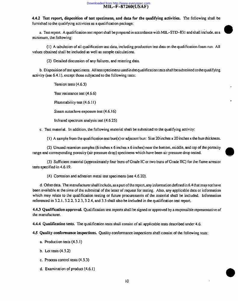
4.6,4 Porosity (airpressurt drop) test. Theporesizedetennination shell be by the air pressure drop tecbniquespecitiedherein. ‘IWOspecimens persampleshall be run for production tests and thee specimens per sample for qualiticetion tests.The cylindrical specimen shall be 10 inches in diameter by 1+3.02 inch thick, where the one inch dimension is in theheight direction of the test section. Forprcduction tests the porosity test specimen shall be taken with the top and bottomthree inches of the teat section. For qualification testing, the three specimens shrdl be taken from the same Iccation butfrom the upper, middle, and Iowerpordom of the bun height. Pressure drop measurement shal be made using a porosit y
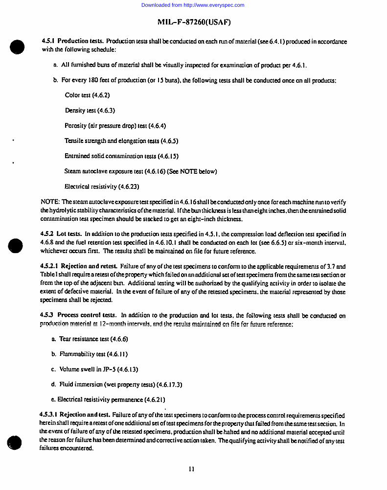
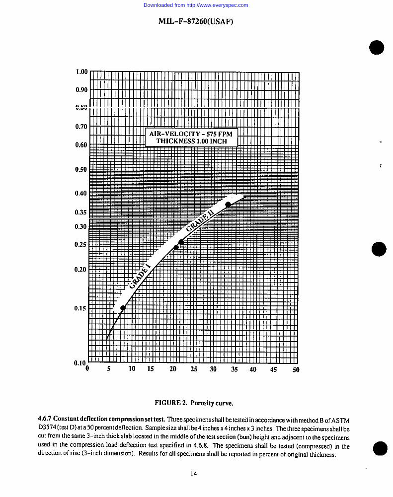
test rig (see Figure 1) which haa E&mproped y calibrated. Calibration shall be conducted on a daily basis using either asp-xial pressure drop screen or orifice plate in or&r to determine the reference setting for the orifice differentialmanometer, or a correction factor that accounta for density variations of the air. Prior to snmple testing, the manometerwhich indicates the air flow shall be adjusted to zero with no airflow. The spezimen shall then be inserted into the sampleholder until it is proped y seated into the cutout. The blower shall be started and the eirflow set to coincide with the deil yreference calibration setting on the orifice differentitd manometer. Next, read the sample pressure drop (urrcorrccted) tothe nearest 0.CQ5inch on the 4-inch manometer (designated sample differential). The value shall then be corrected forthicb%ss (if other than 1COinch thickness) by dividing it by the meaaured sample thickness. IWS corrected air pressuredrop shell then be compared to the porosity curve (Figure 2) in order to determine the average pore siz for the samplespecimens, The sample pressure drop shall be reported. NOTE The porosit y valuea shown on Figure 2areassigned for
reference only and do not neceaaarily relate directly to the achml numbsr of pores per lineal inch. ●12
Downloaded from http://www.everyspec.com
MI L-F-87260 (USAF)
EXHAUST
/’
I AtR FLOW’ADJUSt%tEUT
SUOE ORMCEVALVE SAMPLS
HOWER
FIGURE 1. Typical permit y (air flow) test oppnrntus.
e 4.6S Tecmilestcength cmd ulticcsnteelongcrtion tests. Tension tes.s, inchrdiig tensile strength and rdtirrrmeelongaticm,shall be conducted in accordance with ASTM D3574 (TksI E),excepI that the tiIurd jaw separation shall be.2.Oinches A2.5-icrch jaw separation may k used for $orrsiste.ncywith otier preducts. hmvever, dam must be provided in thequalification report showing Orecorrelation between the Iwo grip lengths. For elongation measurements there sre Iwospproved techniques, benchmarks and crosshead travel. ‘he rate of uavel of dre power acnrafed grip shall.& 20 *Iirrch(es)per minute and shall be uniform at all timca. l?te specimen die to be used shall be in accordance with the Figure Iof ASTM D3574 entitled “’OieFor Stamping Tension Specimens”. llre approximate size of the dry specimen shall be.5.5inches .s I inch x 0,S0 inch thick. The specimen thickness dimemsionshall be bstweerr O.5W and 0.600 inches. For sII butqucrliticotion, rhree specimens per sample shall be m-stat. [f my vrduedeviates more drmr20.0 percent from Lheaverage,Iwo nddi!iorrsl specimens shall be rested srrd the average of all five reported. For qtilticstion, 10specimens shall bs
tested snd all vtdues rcpmted. In addition. o copy of the recorded tmces shall be included in the tesI repmt. The wnsilestrersgthshall be reported in pounds per sqtmre inch, and ultimsteelongntiors irrpermrrt. Tension s~irrrensshsil Lmtakenfrom the upper hslf of tie Iesl section, and Llreorientation shall be such that rhe IL&inch dimension (5.5 inches) is slwaysin the machine direction (see 6,6.4). For special fuel-wet tension tests, the specimens shrill be measured curthe dryspecimen prior to test fluid e.xpmure and secorded for la!erusag~ When testing the specimen, ii should be removed from
the fluid prior to rerrsiontests. dmined. arrd immechxely tested. Do not allow tksesample toairdry, as it will stkt the testresulrs. Origirml dcy s~imen dntn shall Ix used ss nbaseline for calculating the percent 1sss in wet tensile strwsgth fortests in 4.6. 17b.
4.6.6 Tear resistance test. Thre specimens strsll lx tested in crccordsrrcewith ASTM D3574 (Test F)using ocrosshead
s-Of 2011 ifi(m) Wr mirruie. DIYspecim~ siz=til be 6 inches x 1icrchx I inch where the 6-inch dimerrsion is inthemwhinedirection snd the slit cut is psmlle.1tothedirectionof rise. Thetesr resistsnceshall be repotted in pormds PSClineal inch of thickness. Specimens shall bs cut from one inch thick slabs of msterisl. For fud-wet tar resistsrw tests
o
(4.6, 17b),thespecimers shall be tested immediately after removal from the fl.id. Originnldryspximendstnshsllbeused
ss a baseline for sslctdating the percent Ims in wet mm resistance.
13
Downloaded from http://www.everyspec.com
MIL-F-87260(USAF)
1.00
0.90
0.80
0.70
0.60
0.50
0.40
0.35
0.30
0.25
0.20
0.15
0.10‘O 5 10 15 20 25 30 35 40 45 50
FIGURE 2. Porosity curve.
4.6.7 Constant deflection compression set test. llreespecimens shsll be tested in accordance with method BofASTMD3S74(lestD)a!a50percent deflection, Semple size shsll be 4 inches x4 inches x 3 inches, The three specimens shfdlbecut from the same 3-inch thick slab located in the middle of the test section (bun) height and adjacent to the specimens
used in the compression load deflection test specified in 4.6.8. The specimens shsll be tested (compressed) in thedirection of rise (3-inch dimension). Results for all specimens shsll be reported in percent of original thickness.
14
Downloaded from http://www.everyspec.com
MIL-F-87260(USAF)
4.6.8 Compr-cssion Iond deffcction (CLD) test. ‘fWeespecimens shall be kxed in accordmcc with ASTM D3574 (tex
C)ot the2S percmt md 65 Percent deflection level sfter I rrrirmtentmchdeflection point. Specimen sire.shall be4 inchesx 4 inches x 3 imhes srsd taken near tlM middle of the hm height such tha! the 3-irsch dimmsion is in the dirmiion ofnsmerisl rise. Tfse rate of compression (deflection) shsll be IWOinches per minum New material shall be sged for aminimum of 96 hcmrs following thermsl reticulation prior 10 compression land deflection testing. Tess shsfl te
conducted in the direction of material rise. Prior [o ms[ing. the specimens shsll be preflesed twice to W fsercemcompression. A copy of the recorded trscm for mch test slsaflbe included in the test report sml restdu reported in pounds
per squsre inch. For weI compression load deflecticm propmies the test specimen sfd be tested irsrsrcedhedy afterremovel from the fluid. The origirrsl dry speimen &to shnJlbe used ss o baseline for determining the percmt loss in weIcompassion load deflection properties per 4.6. 17b.
4.6.9 Fuel displacement tsst. OrE sample per test shall be run using grade JP-5 or JP-8mrbine fuel conforming to
MIL-T-5624 or MIL-T-83 133 respectively. mrd the oversge reported us the fuel displacemmt. Tire @t shafl beconducted u sumdmdcorsdhiorss using nstmsdnrd 1.@) milliliters (ml)mpmitycylirsde.r having 10to 20 ml graduations.Each specimcrr shafl & cut into a cylincfrictd shape having a dismeter approximsmfy equal to drat of the graduatedcylinder and o length sufficient to till dcelest cylinder to the 900 ml mark. Specimens shall te cut in the direction of thematcrisl risc(bunheight). Fuel shsll be dded to the5UOml mark in thegradunmsfcylindermd the s~imenslowl ysddcduntil it is completely immersed. The specimcrr shall be immersd for a pericd of 24 hrnms(o obioin maximum swelling
effects. The new fluid level shsll be noted and the imrense in milliliters shrillh romrded. 711esiseof each specimen shallbe messured end recorded. The displacement shsfl be csJcrdaIed as follows
Percem Volume Di.rp.kccmem =millimeters increase X 1CO
original J7uid volume
4.6.9.1 Thmretimf fuel dKplncemmL The tieoreticd volume displmemeru of the miuerisl sc cnlmdated from thefollowing fornsrdn and bused on the material derssity specified in 4.6.3 shall be reporterl
Percem, displacemem(vof) =material dcm”ry (fbJ/jP) X 1W
&ruify of poplpl(s) polyrncr (fbs/j?)
4.6.10 Fuel and water retmtiorr tssts
4.6.1O.I Fuel retention tssts. Fuel reterscionshsll be determined on a 6 inches x6 inches x 6 inches specimerr using grede
JP-5 orJP-8 tcubme fuel conforming to hlIL-T-S624 or MIL-T-83 133 respectively, havin~ a specific grnvhy ofO.788100.845. For quslificntion testing the retenciorrvalues shrdl be dehmrrrinedthroughout the permit y rmsgeof the productand the datoplotted us a function of air pressuredmp. A minimum of drreediffsreru retemimsspecimeru et three differentporosity locations (lower, middle, msd uppsr porosily ranges) shaJl be tested for esch type of msmrial. At each testICcatim four retcmicmspecimms shrill be cut from the cmter of the respective as! section (bun) height dirsd y adjscmito esch other. These shall be identified M the mp surface, md two each shall be idmtified for the tie] retmlion tesIspecified herein and the wster retmtion tesI specified in 4.6.10.2 A porosit y test specimen shnflbe takersdirdy abovemd tcfow the retm:ion specimm and tested per4.6.4. All recmtimr nml pmosit y (nir pressure drop) specimens shall be
P-rlY isbe.l@ OIS~ toP surf~e Md subtitted to the coordinating nctivity. One fuel retention specimm from emh ofthe three test locations stmfl be tested in mcordmscc with the following procedm msd nfl applicable data shrdl berecorded:
a. The spcimm shsfl be preconditioned at 0 kmpemNre of 75 ti°F for 0 minimum of 30 minutes, weighed to thenenrest 0.1 gram, and the dimensions measured in accordance with Am D3574. l%e test tlrdd shsfl be prefikered
Downloaded from http://www.everyspec.com
MIL-F-87260(USAF)
through aO.8-micron filter aa specified in 4.6.15 and then adequatel ypreconditioned at the test temperature. Just prior touse, the fluid shall be tested for specific gravity (demity) and temperature. ●
b. The retentionks apparatus shall be sized to approximalel y 7 inches x 7 inches x 10inches and shsll have a meansof draining the fuel from the bottom at the rate of 500 *5O cc/minute. me draining drOpmte in t~s P~tic~m aPPmatusshould approximate 0.5 inch per minute. The test fluid shall be charged into the conteiner to a level which corresponds to
approximately 0.5 inch above the mp of the specimen.
c. The spsci men shall then be slowly placed into the container such that the specimen is oriented in the direction ofrise (bun height) and supported off the bottom of the container by two glass rods and spaced 0.5 inch from all sides of the
container, Fuel shall then be drained at theprc.scribed rate until flow cease$ and the specimen then allowed to drain in thkposition for an additional two minutes.
d. The specimen shall then be careftdl y removed from the container and weighed tOthe ne~est 0.1 gr~. are shOuld .be taken not to spill the fluid from the bottom surface of Lhespecimen when removing from the t=l rig. Using thespecimen weights before and after fluid-wetting in grams. specimen volume in cubic centimeters. and fuel density ing-ramsper cubic centimeter, lhe percent volume retention shall be calculated as follows:
~ercen, ,eten,ion = (wet spec, WI - dry spcc. WI) X 100
specimen volume X density of fuel
e. All values, including test fluid temperahlre and porosity values (topibottom), shall be reported. The aboveprccedure shall lhen be repealed, using the same specimens, and report results.
4.6.10.2 Water retention kst. Using one unused water retention specimen specified in 4.6.10.1, the volume percent
retention shall bedetemlined using the same procedure. This shall be repeated for at least one other porosit y location. Thetest fluid shsll be unused distilled water which has been tested for temperature and density just prior to use. CAUTION: ●Do not run more than two tests per batch of water.
4.6.10.3 Test data and sample requirements. Report test data on all samples tested including the airpressuredrop of thespecimens directi y above and below the retention samples. A minimum of three specimens from various locations withinthe porosity range for a material shall be evaluated and a curve of fuel retention versus air pressure drop established. Tnedam (curve) shall be extrapolated to the upper air pressure drop limit and the projected fuel retention limit shall beestablished and reported. A fuel retention sample for each data point along with the tested porosity samples shall beidentified and submitted to the qualifying activity (see 6.4. I).
4.6.11 Flmnmabilit y test. Five specimens shall be tested in accordance with the pr~edure specified in Appendix B.Specimen size shall be 6 inches x2 inches x 1f2 inch. Flammability specimens shall be taken from the upper half of the test
section, and the orientation shall be such that the &inch dimension is in tie machine direction (length) md the l/2-inchdimension is in the direction of rise (height). Alltestvalues shall be reported and the average flammability shall becalculated in inches per minute.
4.6.12 Extractable materinf test. The extractable material teat shall be conducted on one test specimen. The specimensize shall be I inch x I inch x 2 inches and cut by means of a saw or die. Preconditioning of the specimen shall include
drying at 200 ~5°F for 15 minutes and cooling the specimen in a desiccator for a minimum of 30 minutes. Immediate yfollowing the preconditioning, the specimen shall be weighed to the nearest 0.10 milligram. ‘fhe specimen shall then beplaced in a 60 ml volume Soxhlet extraction tube which is connected to a water-jacketed condenser. Several standardboiling stones and 125 ml of Type Ill test fluid conforming to~-S-735 shall be added to a 250 ml Florence flask and theftw,kauached to the extraction tube. The heating unit shall be activated and the fluid allowed to reflux for a pericd of thre
hours. Following reflux, the specimen shall be removed. dried at 2C0+5°F for 15 minutes, cooled in a desiccator for 30minutes and then weighed. The ~rcentage of extractable material shall be calculated as follows: ●
16
Downloaded from http://www.everyspec.com
MIL-F-87260(USAF)
I10
.
i.
~er==nt ~roctnb,e = (orig. specimen weight - fill weiglrf) X 1@3
original specimen weighr
4.6.13 Volume swell test. One specimen for each test fluid shnflbe tested for volume changes after immemion for7 cfnys
m 7S ~5°F in T@ I test fluid conforming IOIT-S-735. Type III test fluid conforming to 7T-S-73S, mrdgmde JP-4.JP-5corrfonning IoMIL-T-5624, anrJJP-8nrrbiie fuel confomring IoMIL-T-83133. Smnfrlesizeshall be6inches x 6inches x 6 inches. ‘he smnples shsfl bs token from the smne approximate Iccoiion in the test sec!ion ss the rctemicmteslspecimens specified in 4.6,10. Dry and wet measurements shall be made on tie mmspecimens in accordance witi ASThlD3574. Following immersion. the specimens shrillbs removed snd immedmel y meosumd wet for the final volume. Allvafues for the specimen including original msdwet volumes shall be reported msdthe pemem volume increase from Iheorigimd snd we! messuremems shall be colcufnted.
4.6.14Low tempcmtureflexhilitytest.Threespecimens,2 inches x 1/2inch x 12inches shafl & preconditioned in sir
sfong with a 3-inch disrn.aer rod to a renrpemture of -55i5°Fforonehour.W specimenshallkecutsushha the12-inchdimensionk inhemruhine diremion. Al the end of theccmditioning period ond wishmo removing rhespecime.nsfromthechmnber, each specimen shrillbe bent amundtherod, Anyevidenceofbmaking orcmckingof fosmslrmsdsshall
be cause for failure.
4.6.15 Entrained solid contamination tests. Solid conmorirmtion tests shall&conducted onahot-wire-cut cylindricofspecimen having dimerssions of 9.25 inchesh dismelerand8irschmin height. The 8-inch dimension shall te cut in Lhe
direction of rise (bun height). For mnterisl having more than [email protected][ticnfromrhelowerportionof the testsection, Testing shafl be conducted using o U.S. Testing Compsny model 6523 dry cleoning
machine orequivatem, having a tumbler rotation sped of 45 rpm. The specimen shafl be positioned in tie cemes of the
omrmbler.The tes! cycle shall be 3 minutes usi~ o4-liter chmge of Type 1fluid conforming IoTT-S-735 which hns bpre-tihered dsrough a O.S-micron Millipme Filter Corpomtion filler, or equivalent. Upon completion of Lhetesl cycle.
h specimen shall&positioned slightl y above he fluid level and oJlowed fodrairr for five minutes prior to removal. Thetest fluid shfdl thenbs Ie-stedfor level of solid comsrnirmtion in accordance with ASTM D2276, Appemlix A3 (labomtowfiltration) or T.O. 42B- I-1. Sections 5-23,5-24, msd5-47 through 5-52. Following filtration of the test fluid smdjustprior to removal of the filter pad from the nppnmtus. the filter snd con!mtrination shall be neuualiti of static charge wiilsa Nuclear l%dums Company Model 2UY32nir deiorrizer. or qm”vdent (see 6.9). Tfrisstep reduces the loss of panicles
from the filter psd during transfer to the drying oven. Erich filter used shall be dried 012CY3*5°F for a minimum of 1Sminutes and then cooled for o minimum of 15 minutes. A minimum of one control tiller shell be nm for eoch set of
smnples. Test results shall be reported in milligrams per cubic foos of mrtterinl.
4.6.16 Sterrm mstoclnve exposure test. Testing shofl be conducted in accotds.nce with ASTM D3574 (tesl J) stemn
autoclave us for 10hours m 2S0 +5”F. Tension tests m specified in 4.6.S shell te cmsducted on five comml specimens
and five e.xpusedspecimens. Prior to resting, exposed spscimem shsll bepmt-dried for 30 minutes a! 160~5°F snd theIscooled at room temperature for 30 minutes. The results for tensile stsength snd e[ongotion shsf[ be repcmed bsfore ond
after exfmsure and the overage percent change in tensile strength cofcuhuecf.
4.6.17 Ffuid “tiersion tests. Fluid exposure tests, shall be conducted cm the baffle moterioJ under the followingexpusure conditiom
a. Grade JP-4 CUSbinefuel conforming to MIL-T-5624 for 12weeks M 160~5”F. Tension snd Electrical Resistivit ySpecimens, per 4.6.5 and 4.6.4 respectively, shall also be exposed to the test envimnrnem.
b. GmdeJP-4 turbine fuel conforming to M[L-T-5624for4 weeks st 75i5°F. Todetermins the wel property vafues
o
for the material, tension, CLD, and tear resistmrcespximens, per 4.6.5,4.6.8, msd4.6,6 respectively. shsfl be esposed tothe test environment, and then tested fuel-wetted for all profwties.
17
Downloaded from http://www.everyspec.com
MIL-F-87260(USAF)
4.6.17.1 Tension tests. Tats in accordance with 4.6. 17a shall bc condrrctcd irrIcosely capped standard quart jars using
approximately 9~f25 ml Offl~d fOrah tie $p=ima foresch s~pling frequency. Sptcimens shall be taken fromthe upper half of the test section as specified in4,6.5. The testig frequency foresch condition shell be every four weeks.me JP-4 fuel shall be chsrrged at each four-week interval. Testing shall include three specimcrrs dry tension-tested asspecified in 4.6.5, three specimerrs tested in sccordmrce with the steam autoclave expmare test as specified in 4,6.16, andthee additiond specimens shrdlbe tension-tested while fuel-wetted in accordance with 4,6.5. Prior to dry tension and
steam arrtcclave testing, the specimens shrdl be rinsed in petroleum ether, dried for 30 minutes at 160*5”F, endcooledatroom temperature, Wet ten.ciontests shsll be run inrrrdately titer removal from the test fluid. All values for originat,find (dry snd wet), and percent change of tension properties shall be reported. The wet tensile properly chmge shall becdcrdated using the initial (time= O)wet tension vslues as a bmeiine.
●
4.6.17.2 Electrical resistivity test. In addition to the tension tests of 4.6.17.1 electrical resistivity tests shall beconducted using specimens defined in 4.6,4. A total of six specimens shall be exposed to the fuel mrdst mch two-weekinterval a specimen shall be removed, washed in petroleum ether, dried, and then tested per 4.6,23. The specimens shall
also be test.d inhirdly, prior to immersion into the fuel. At each four-week interval the fuel sbsll be chsnged, AUvaluesfor original and final electrical resistivity shall be reported along with the test conditiom (temperature turdhrrmidity) thatexisted during the electrical resistivity tests. The electrical resistivity tests shsll be in accordance with the procedures forprcdrrction specimens detined in 4.6.23.
4.6.17.3 hnmeraion tests.Fuel (JP-4) immersion tests in accordance with 4.6. 17bshall be accomplished in containerssti!cient to provide complete immersion for all tension, CLD, and tear specimens. Following the 4-w.a?k exposure at
75 ~5°F (room temperature), three specimens shsll be imrnedkely tested for wet tension prqmties in accordmce with4.6,5, wet CLD propenies in sccordmrce with 4.6.8, and wet tesr resistance properties in accordsrrce with 4.6.6. Allvalues and averrrgcsshall bc reported rmdthe percent change from the original dry test properties shall be calcrdatcd. Theoriginal dry property data detemrined in 4.6,5,4.6.8, arrd4.6.6shordd be used toestablish the percent change inpmperdesdue to fuel-wetting.
4.6.18 Hydrolytic stnb[lity tests. The following tests shall be conducted to chmacterize the hydrolytic stabilit y of the ●materiak
4.6.18.1 Humidity expnsure. Terrsion ad electrical re.cistivity specimens shsll be exposed to 200 ~5°F ard 95 *5
percent relative humidity for 12 weeks or until failure, whichever cccrus first
4.6.18.1.1 Tension teat% Tension tests shall be conducted in loosely capped standard glass quint jars using 50 mls ofdistilled water for esch 900 mls of container volume snd a maximum of nine tension specimem for each ssnrplirrg jar.Specimens shsll bcsuppmted above the water rmdthe water level shall be msbrtained throughout the test. A minimum of
three specimens for esch exposure time shall be t.wsile mated, fn addition, electrical resistivhy tests shall be conductedusing specimens defined in 4.6,4. Suftlcient specimens shrdlbe used to allow samples to be removed at Icast once a weekin order todetermine the failure point for the conductive treatment or coating, All resistivit y specimens shall be measured
initial]y (prior to exposure) to .Wablishpropertychmgea due to testing. llre test specimens shall be removed, dmined free
of water, blotted dry, and then air dried at 160 @F foraminimum of 30 minutes prior to sny preconditioning forres.istivityevaluations. l%e resistivit y specimens shsll then be tested (following preconditioning) in accordance with4.6,23. Water ased in the containers shall be maintained mrdchsnged on a weekl y bssis. All values for original and finslelectrical resiativity shall bc reported along with the teat conditions (temperature@ercent relative humidity) that thespecimens were exposed to during the resistivity rrreasurements.
4.6.18.2 Water immersion. Tension specimem shall be immersed in pure distilled water at 1&l~5°F for 12 weeks oruntil failure.
4.6.18.2.1 Testing frequency. Testing frequency and water changes shall beat four-week imervsls. Three specimens
shall be tested for each sampling frequency. Testin8 shsll reconducted in loosely capped jars using 900+25 mls of waterfor each of the nine tension specimens. Water used in the containers shsll be changed on a weekly basis.
o
Downloaded from http://www.everyspec.com
I
I
I
IIII
●
✎
0
I
w
MIL-F-87260(USAF)
4.6.18.3 Dry heat. Tension and electrical resistivitys~imens shall keexpmed to dry twit M2SO*5°F for eight weeks or
until frlihlm
4.6.18.3.1 Testing frequency. The testing freqency shall be at two-week in!ervsfs, A minimum of three tensions~imms shall be tested for each smnpling frequency. Addhiorrsl specimens shnfl be esposed for electrical resislivityevrdrcations. The specimens shall be in accordance with 4.6.4sndshsllbelesled,m aminimum, on a weekl y basis. Prior
tothestsn of h tesl.theelecuicnl resistivit yspecimens shall kemsmd arsdthe test conditions recorded lxr4.6.23. Al testdata shall be reported inchdng test condi[iorrs (tempemturehelmive humidity) for the elecoiml resistivity evduaiions.
4.6.18.4 Datn requirements. All tension and elecuicsl resistivity sewdfunobtaimd under 4.6,18 shsll be reponed per
4.6.5 as well ru percem lass in tensile strength In oddition, the mn.silestrersgth srsdelectrical resistivity vslue-sshall beplotted m a fimction of expasure lime
4.6.19 Explosion suppression md ftanse rwr-extor chamcteristics. The explusicm suppression msd flnrne srmstor
chsmc[eristics of the msterinf shall be defined using o smsll scale flmne tube type apparotus having n minimum tomlvolume of 5 cubic feet and n 103 square inch cross-sectiorm.l area The following pamnseIers shsll be satisfied in M the
testing:
a. Stoichiomeuic propwm/nir mixture (4.5 m 3.2 volume percent propane) verified by bomb sampling
b. Spsrk ignition source having o rssinimumof 0.25 millijades energy
c. Dry srre-stor material
d. Mhimum imnmssmu!tionshaklincludepressurerise,combustionlempemtureindication, and visual,photographic, or photocell indication of flame penetration downstream of mm.stor.
e. Combustion relief mea slmll be 80.0 percent of cross-sectional men or grater. lle msterial used for rJretestingshsfl te Isken from o given bun which hss keen suffrcieml y tested to e.stsblish its air pressure drop (porosity) smddensitychmncteristics. The materisl shall slwoys be orimted in the test appam!us to penssh flsme perseus.cicmin the direction ofporosity k?sting (direction ofriceorbun height),
f. Mere pm.clicak,the ma!erisl used shrdl be in the lowerhnlf of the air pressure drop range Forexmssple: Grede Islmll be between 0.150 and 0.203 inch of water and Grade [1 shall be between 0.264Jand 0.310 inch of water.
4.6.19.1 Mnterisd sizing. The materisl shafl slwnys & slightly oversized, 2.0 percent msximrms, whm instslled andrestmincsused to avoid arrestor movement during mstirsg. llsecomb.stible mixnueon esch test shall be verified by Ixrmb
smpfing ~d sIMIImeet the followingrssinimumcriterinforpressureriw
A P*= (Wo) X 0.7, where P- = irrhiol pressure of systcm in psia.
The following definitions shall apply (see Fi#we 3).
psid = differcnrial pressure rise smrtin.c csoint maximum oversrressure wiru durin e [heco–idrrution protess
V. = orrestor volume
V< = combustion (ignition volume)
V, = relief volume = V, + V,
V, = total volume of apfmrarcrs =
-. .
v= + v,
V. . wid volume dos+m.rmearn of a,,estor
T. = miru”murn arrestor thickness required preveru flome propgarion V. to V.
19
Downloaded from http://www.everyspec.com
MIL-F-87260(USAF)
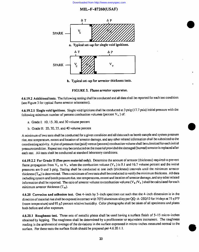
A’f AP
SPARK
a. Typictd set-up for single void ignitions.
‘P+IZ!ZFIb. Typical set-up for arrestor tbickne.ss tests.
FIGURE 3. Flame nmeator apparatus.
4.6.19.2 Additional tests. The following testing shall be conducted and all data shall he reported for each test condition(see Figure 3 for typical flame arrestor orientation).
4.6.19.2.1 Single void ignitions. Single void ignitions shall be conducted at 3 psig (17.7 psia) initial pressure with thefollowing minimum number of percent combustion volumes (percent V, ) of
a. Grade I: 10, 15,20, and 30 volume percent
b. Grade 11:20,30,35, end 40 volume percent
●
A minimum of two tests shall be conducted for a given condition and all dsta such as Lmmbsample snd system pressurerise, test temperature, extent and location of westOr @age, ad ~Y O~er rel~~ tiO~atiOn sh~l ~ submitted tOtiecoordinating activity. A plot of pressure rise (psid) versus (percent) combustion volume shall Eesubmitted for each initislpreasurecondition. Repeat test may beconductedon the material provided Uredamaged (burned) srrestoris replaced after
each test. All tests shall be conducted at standard laboratory conditions
4.6.19.2.2 For Grade U (fine pore material only). Determinetheamountofarrestor(thickness)requiredtopreventflamepropagationfromV. toV, whenthecombusdonvolume(V.)k 9.1and16.7volumepercentandtheinitialpressuresareO and3psig.Testingshallbeconductedat one inch (thickness) intervals until the minimum arrestorthickness (TJ is determined. hen a minimum of two tests shall be conducted to verify the minimum thickness. All dataincluding system and bomb pressure rise, test temperstum, extent and Iccation of arrestor damage, and any other relatedinformation shall be reported. The ratio of arrestor volume to combustion volume (V./V.)shall be calculated for eachminimum arrestor thickness (TJ.
4.6.20 Corrosion and adbeaion test. Gne 4-inch by 3-inch sptcimen cut such that the 4-inch d]mension is in the
direction of material rise shall be exposed in contact with 7075 aluminum alloy per QQ-A-250/l2for 14days at 75 t5°F(room temperature) and 95*5 percent relative humidity. Color photographs shall be taken of all specimens and platesboth before and after exposure.
4.6.20.1 Roughness test. Three sets of metallic plates shall be used having a surface finish of 5-15 micrtiinchesobtained by lapping. The roughness shall be determined by a protilometer or .sqrivslent instrument. The roughnessreading is the arithmetical average of the deviations in the surface expressed in micro-inches meaaured nomral to the
surface. For these tests the surface ftish shordd be preparal per 4.6.20.1.1.0
20
Downloaded from http://www.everyspec.com
MIL-F-87260(USAF)
4.6.20.1.1 Surface finish. A surface Iii”shof 5-15 micro-inches men.smedperpendicular [othetaym oroughne-ss-w”dti
cutoff ra!ing of 0.030 inch ad a maximum roughness-width rmirrgof 0.015 inch. One set sludl be clamped together with
the baffle material specimen such that the baffle materisd is compressed from 4 to 3khes h hkknessinccmmc~wihtiepolished surfaces. Ilds set along widr one set of extra plates (controls) shell then be esposed for 14 days m rmm
temperature and 95 ~5 percent relative humidity in 8 ceded container or hmrridhy cabinet. In addition, the third sti ofplates shall be used 10nm a comparison test on the vendor’s basic blue polyether fomn hnving dre same porosity as I-heccmduciive material. Test specimens should be oriented such thot the meted plmes ore venicd in order to minimizemoisture condensation nrrdpooling on tie plate surfnces. At the tcmrinmicm of the lest. there shall be no mlhesion of the
baffle ma!erinl 10the metal plums nor shall there be my evidence of pining, errssicm,corrosion, or bnd discoloration as arssrdt of che maserial conmct, as determined by the following procedures. The basis for the comparison slrdl kc dreespascd set of Cmrtrol plates.
n. The surfncea of the plat= which were in corm?ct with the material shall be inspected for such thirgs asdiscoloration, d~its, and pi!ting. If any of these condkiorrs exists, the sucface of the places shall be washed inprecipitation naphtha. Llqmsita defernsirsedw urechmremaferinls or elemems. which carr be removed by this prcce$s,shall be corssmmd as adhesion.
b, If rmyother marks renrnin on the surface of the placeaafter bekrg wndred in precipitation naphtha as spxifred in4.6.20.1.1 n. the surfmes shall te Iightlypolished with o nombrasivecloth buff. Any pits or eroded marks remaining afIer
Usispnxessshnll becorrsttued[obe corrosion. Oiscolomtionorsm”crirrg (mnrks which donotphysically fiec[ the surfaceof the plates and which easily wmh or buff off) shall not be considered detrimental.
4.6.20.2 Test report. All test tin, including the phomgmph$, shrill be included in the test report. in oddilion the testplates shall also be submitted to he qurdifying aclivity.
4.621 Electrical resistivity pcrmmsence
4.621. I Writer immersion. ElecIricaJ reaislivity specimens, per 4.6.4, shall be immersed in pure distilled waler al120
i5°Ffor12W* ormtilftrilure.llresmne12-weekesposurcat160#F maybesubstimwdforhismmpemmre(see4.6.18.2).Forprece-sscontrol testing, the test lime nmy te reduced to four weeka.
4.6.21.1.1 Electrical seaistivily specimens. Sufficient electrical reaistivity specimens shall be included to alluw forspc.imerr removal a! least !wice a week. The specimens shall be tested for irsilinlreaislivily prior to water expcmrre 10establish nbaseline. AI least one specimen shall be removed from the tesI environment lwice weeldy. and upon removal it
shall be dried m Id3fi°Ftcntil dry and thm preconditioned Iothe Ioborwory conditionsforatleast30minums.Fcdlowingpreecsditioning, thespecimerrshnll be tmtedpm4,6.23 msdreinsercsd intothete-st erwiromt. ‘fhedis[illed wruershallbe ceplaced on a weekly basis. All initial nrrd frsal electrical resistivitiea shall be reported, as well as OHteat ccasdkions(tempercaum and humidity) during resistivity mmsurementa.
4.6.22 Fuel cssmpntibifhy tcsL MIL-T-S624 (gmde JP-4) and MIL-T-83 133, (grade JP-8) fuels shall be expmed to
the conductive material for four weeks a! 75 ~S”F and then Icsmclfor tie properties listed below. The fuels shall also betested prim to the expmure as indicated. lle ratio of conducive mncerial to fuel shall be qspmximately 1:1. llse foamcolor~lgmmt change (loss) shall be documenk+ following expsure to verify the re@remem! of seaion 3.4.
EueLmlxnY ctrmmksl AfwEsmuea. saytrd color YES Y&s
b. Total acid number YES YES
c. Ammatim and olefm YES NOd. Mercaptm SldfW and total YES NOe. Oistillntion YES NOf. Density YES NO
21
Downloaded from http://www.everyspec.com
MIL-F-87260(USAF)
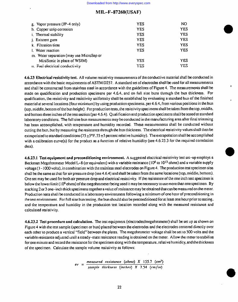
g. Vapor pressure (JP-4only)h. Copper strip corrosion
i, Thermal stabilityj, Existent gumk. Filtration time1, Water reactionm. Water separation (may use MlcroSep 0!
MiniSonic in plsce of WSIM)n, Fuel electrical conductivity
YESYES
YESYESYESYES
YESYES
NOYES
YESYESYESYES
YESYES
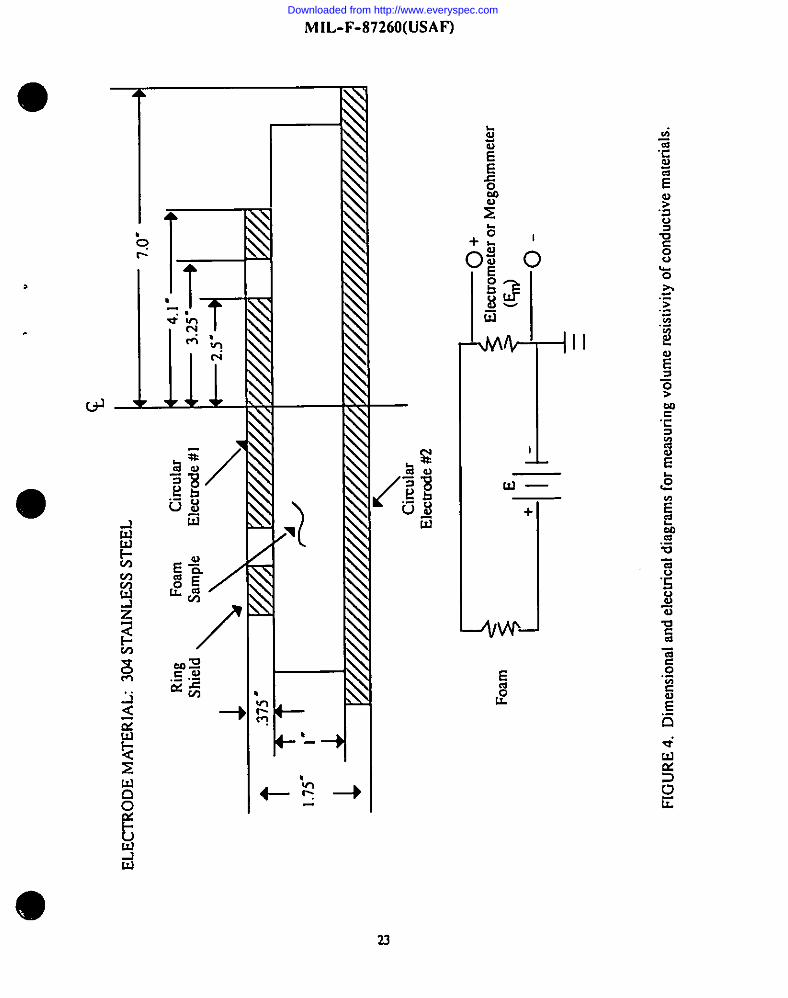
4.6.23 Electrical resistivit y test. All volume resistivhy meaauremcnts of the conductive material shall be conducted in
accordance with the baaic requirements of ASTM D257. A standard set of electrodes shsll be used for all messurememsand shsll be constructed from stairdcss steel in accordance with the guidelines of Figure 4. The measurements shall bemade on quslitication and production specimens per 4.6.4, and on full size. buns through the bun tiickncss. Forqualification, the resistivity rmd resistivity uniformity shall be established by evaluating a standsrd bun of the finishedmaterial at several locations (four minimwn) by using production specimem, per4,6 .4, from vsrious positions in the bun
(top, middle, bottom of the bwrheight). Forprcduction tests. theres.istivity specimem.shall betsken from thetop,middle,and bottom three inches of the test section (per 4.6.4). Qualification and production specimens shall be tested at standardlaboratory conditicms. The full size bun measurements maybe conducted in the manufacturing area after find trimminghsa been accomplished, wilh temperature and humidity recorded. These measurements shall be conducted without
cutting tie bun, but by measuring the resistance through the bun thickness. The electrical resistivity values shall then be
extrapolated to stsndsrd conditions (75 +5”F,55i5 percent relative humidity). The extrapOlatiOnsh~l ~ ~cOmplishedwith a calibration curve(s) for the prcduct sa a function of relative humidity (see 4.6.23.3 for the required correlation
data).
4.6.23.1 Test equipment md preconditioning environment. A suggesksxlelectrical resistivity test set-up employs a●
Bwkmm Megohmmeter Model L-8 (or equivalent) with a vsriable resistance ( I@ to 1013ohms) and a variable SUPPIyvoltage (I- 1CY.30volts), in combination with the stainless steel electrodes on Figure 4. ‘he production test speximen size
shall be the same as that for sir pressure drop (see 4.6.4) and shsll be taken from the same locations (top, middle, bottom).One set may be used for both air pressure drop and electrical resistivit y. If the resistance of the one inch test specimen isbelow the lower limit (l@ ohms) of the megohmmeterbcing used it maybe necessary to use more thsn one specimen. Bystacking 2 or 3 one–inch thick specimens together a value of resistance may be obtained that can bc mcssured on the meter.Production tests ahdl be conducted in a laboratory environment following a minimum of one hour of preconditioning in
the test environment. For full size burr testing, the bun should also be preconditioned for at least one hour prior to testing,md the temperature and humidity in the production test location recorded along with the measured resistance sndcalculated resistivity.
4.6.23.2 Test procedure and calculation. The test equipment (el.extrcd@rnegohmmeter) shall beset up sa shown on
Figure 4 with the test ssmple (specimen or bun) placed between the electrodes and the electrodes centered directly overeach other to produce a vertical “field” between the plates. The megohmmeter voltage shall be set to 5C0 volts rmdthevariable resistance adJLIStEd until a steady–state resistance reading is obtained on the meter. Allowthemeter to stabilimfor one minute findrecord the resistance for the specimen along with the temperature, relative humidity, end the tlickness
of the specimen. Calculate the sample volume rcsistivity sa follows:
measured resistance (ohms) X 155.7 (cma)f?” =
sample thickness (inches) X 2.54 (cm/in)
22
Downloaded from http://www.everyspec.com
MIL-F-87260(USAF)
,
Downloaded from http://www.everyspec.com
MIL-F-87260(USAF)
4.6.23.3 Correlation test data requirements. A comelation study shall be conducted for the conductive material(s) to
show the effect of temperature and humidity on the volume resistance and resistivity using the procedure and equipment ●in 4.6,23,1 and4.6.23.2. Asaminimum, tiet=t&tashodd ticludetests m75t50Fmd[elativehufidities0f 10.50.~d80*5 percent, and material thickness of 1,4,8, and 12inches. In addition, elcstricfd resistivit y tests shall be run on one
inch thkk specimens at 160 ~5° F, 60 t5°F, 30 &5°F.Of5°F, –20 +5”F, and -30 ~5°F, and all data reported includingrelative hmnidity conditions (if possible). Record all values for resistance, resistivity, temperature, humidity, andmaterial sample overall dimensions (if other than that per4.6 ,4). If the conductive material is found to vary more than twoorders of magnitude as a result of the humidity changes, then a correlation curve or extrapolation factor shotdd be
developed for use on all production bun tests where the test conditions will Iikely be other than 7S~5°F and 50 +5 percenthumidity. Thecormction will enable thequrdifying activit y to know the resistivity value at standard laboratory conditions
(75°F and 50 percent relative humidit y), A plot of resistivity versus temperature shall also be generated to demonstratethe material’s resistivit y properties throughout the anticipated end use temperature range.
4.6.24 Electrostatic fuel impingement test. A fuel impingement test shall be conducted on the conductive material 10
demomwate ita electrostatic compatibilityy. The m-stingshall be done in a small scale rig (55-gallon drum or equivalent).The basic test requirements to be met include:
.
a. lle test tank shall be tilled with the conductive material except fora one to two-inch gap (ullage) at the nozzle inletarea,
b, Fuel requirements: MIL-T-5624 grade JI-4 having the following electrical conductivitics shall be used for the
evaluations: Oto 10,50, 100,2CJ3,500, and 800cu. The base fuel should be from the same batch and the conductivityy levelvaried through the uae of static dissipation additives. The approved additives include ASA–3 (Royal Lubricants Co.
Roseland NJ or equivalent) or STADIS 450 (E.I. dupont de Nemours Co, Wilmington DE or equivalent). Informationrelating to mixing”of the additives into fuel Cm be found in TO. 42B- I-1.
c. Test temperatures: Fuel test temDeraWcs shall include, but not limited to, 150f5”F,64J~5°F, 30t5°F,0y50F, -20 ●15”F. and -30 f5°F. The test fuel temperature is defined as lhe starting test temperature but is not necessarily the fueltemperature at the test end point.
d.Thelesttank shall be fitted with a straight one-inch diameter inlel nozzle. The flow rates simulated shrdl be up to150 gallons per minute (gpm) with an approximate velocity as high as 61 feet per second (fps). The flow rate/velwit y
shall then be systematically adjusted until the associated discharge activity appears and/or ceases. lle critical flowratclvelocity required for discharge activity shall be identified and compared to the candidate material’s critical flowrate/velocitv for a given standardlzml fuel. The absence of discharge activity, at the 150gpm flow rate, may require the.-straight inlet nozzle’s diameter be reduced to allow higher fuel velocities. Any changes in the fuel’s electricalconductivity shall be noted and recorded. In addition to discharge activity, charge transfer levels, associated fieldstrength. and induced voltages on an isolated conductor shall be measured.
e. Baseline fuel impingement tats shall also be conducted on the IvUL-B-83054 orange (Type I) and the blue (TwIV or V) using the same batch of fuel that is used on the candidate material. ‘IMs test dab will be used for comparison totJte data for the candidate conductive material.
f. Appropriate MIL-T-5624 fuel pro~fiy tests (including existent gum. particulate matter, and filtration time) shallbe performed periodically to aid in identifying test facility contamination. Existent gum test should also be runperimlically to control the Cha18e ten&ncy of the fuel which may k affected by the extractabl.es from the candidatemateriaJs.
g. A suggested test setup for the 55-gaJlon test rig is shown in Appendix A of this specification.
4.6.24.1 Test data requirements. The critical flow rates associated with the presence of discharges from flow chargegeneration shall be reported for the candidate mmerird and the blue and orange baseline materials. The associated field ●
24
Downloaded from http://www.everyspec.com
II
I
I
I
I
I
I
I
1
MIL-F-87260(USAF)
●swrgh, induced volmges, charge Imnsfer levels, and variances in fuel conductivity shall also be repmted. In addition,orry vspar ignitions that recur shall be docunrerr!edandtheburnedmaterialretainedforessnrinotion.
4.6.2S Irrfmred spectrum crrrakysistest. Tire conductive material shall be characterized (identified) by an infraredspexomcterusing a frustrated multiple imemrd reflectance (FMIR) technique. llre spectrum shall be of such detail ac to
clearly distinguish it fmm the bsseliw @yether nra!enaf. A reference polyether spectrum shall be included forcomparison. The following cri!erin droll be satisfied where applicable
a. The bslirceof me specuumdetermirrcd at 5 micmssswnvelersgthshall be a rrrirrimmrrof 95 percemttransmittance.
b. The scan speed shall be such as to obtain aptimunr re-solu!ion.
c. A 45” KRS-S prism, Perkin-fZlmer Corporation P/N 186-1595, or equivslesr!, end an FMIR attachment,Perkin-Elmer Corporation P/i+ 186-0174, m qrrivakeni, shall be used to maintain the specimen for analysis. Allequipment used as well 0s details of the test procedure and instrument settings (scan s~, slot sating, etc.) shall be
. identified for hmrre refereme.
4.6.26 Electrochemical corrosion test. This test is irrcendedto iderrtify foam materials that may act as arrelectrolyte inhigh humidity environrrrurts and in the presence of dissimihu metals. The electrochemical corrosion potc$airdof the
cmrductive material shall beevahmoxt by placing it incmrtaa whfrdissirnilarmesah m 120*YFmrd l~P@ r~mive
humidity for 7 days. Measurements of current flow and torso.siomklhesicm shall be made al specified. periodic inten’ols.For comparison, a similar seI of cells, osing h vendor’s baseline blue pol yether (MIL-B-830S4) shall also be tested.
4.6.26.1 Tesdrrg shall reconducted in acondcnsirrg humidit y cabirse!(bath) at 120i5°F for7 days with rrsemuremesctsofirdtiat curreru flow (after approxirnatel y one hcnrcof exposure) and then at 1,3.5, and 7 days. Visual inspectirm and
ephocogmphirrgof the placesforcormion arrdadhmionshall &performed initially arrdtherrat seven sfays. TesIequipmemrequired for the curreni flow rrreasurerneras shall include n Keithley Electrometer Model 616, or equivsknc. The meter
used shnil beset to the IC@anrperescrde. Borrdhrgof thetcst panels shall & with thesomdardrmrrrber 18 or20AWG wireattdred to each plate with “alligator” clarrrps or with copper-nickel print (adhesin) and epoxy overcoat. lle test cellsshall consist of a“sarrdwich”of twostrmdard stak finished metal panels (6 inches x 3 inches x stuk thickness), and thecorrduclive material (6 inches x 3 inches x 1 inch). The comparison cells shall have blue polyerher foarrsof similarpormity substituted in place of the cmsductive material. The meods shsfl conform 10the following specificatio~
a. 30S stairdesi steel per QQ-P-3S.
b. Bare 7075 ahmrinurrr per QQ-A-250/12.
c. Bare 2024 aluminum per QQ-A-25W4.
71re test cell set-up and bonding schematic is shown in Figure S
4.6.26.2TesI metal panels stroll tx?preclcarscclarsdphotographed prior 10the rest initiation. The prrxlearring shall consistof the following steps:
a. f3egmase the plates in a uictrlorcethane vapor pit.
b. Sc.nk the plates in MfL-C-87936 ~ I alkahe &tergcrsI (101 solution) for 15-20 mirrutcs until water“breaks-free”.
o
r,. Wash (deoxidize) in alcoholic/phqsl-roric deoxidiser for two minutes at room [temperatureper ASTM F11iO.
d. Wash in running tap water.
25
Downloaded from http://www.everyspec.com
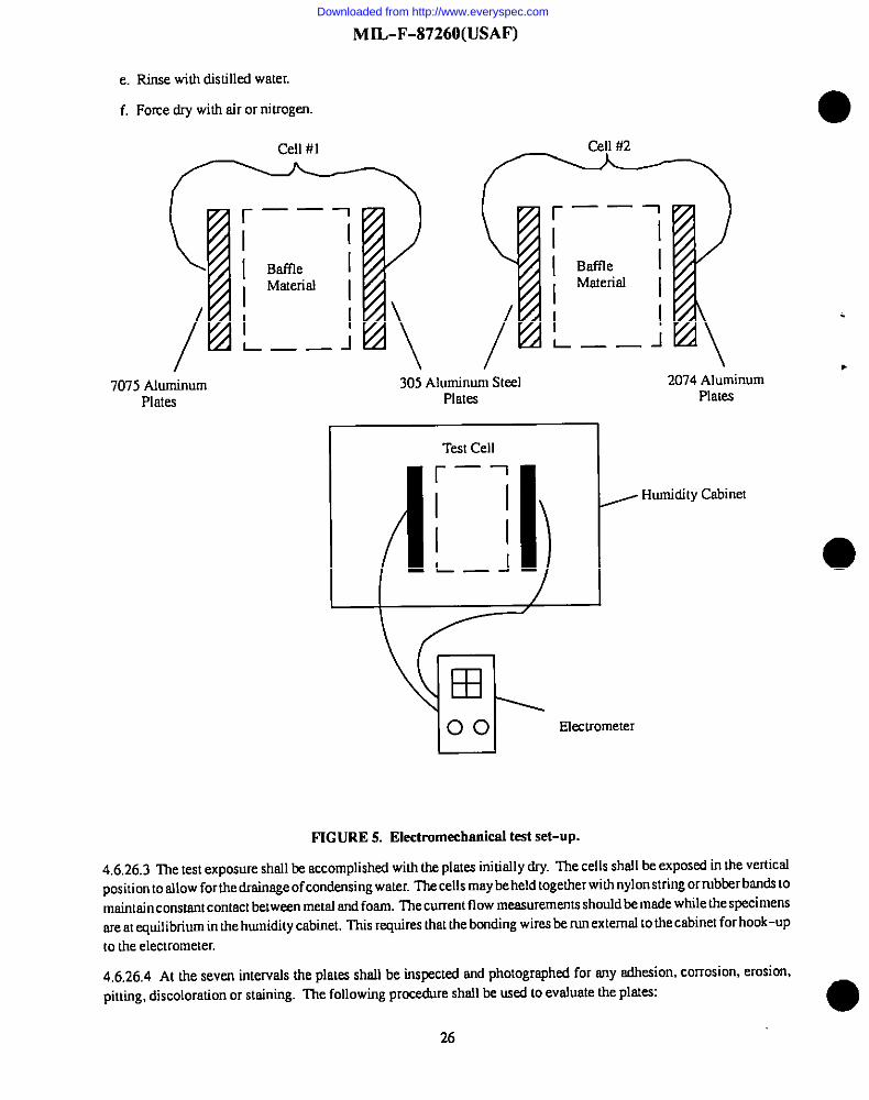
MIL-F-87260(USAF)
e. Rinse with distilld water.
f. Force dry with air or nitrogen
7075 AluminumPlstes
305 Aluminum SteelPlates
r —.1
I Bafile IMaterial
I I
L —— J‘IK -
I Test Cell
r—1
IIIjL—(4!)
\ ,2074 Aluminum
Plates
, Humidity Cabinet
00 Electrometer
FIGURE 5. Electmmedmrrieal test set-up.
4.6,26.3 The test exposure shall be.accomplished with the plates initially dry. The cells shall be exposed in the verticalposition to allow for the dminsge of condensing water. ‘ha cells may beheld together with nylon string ormbberbsnds to
maintain comtant contact between metal and foam The current flow measurements should&made while the specimenssre at equilibrium in the humidity cabinet. Thk requires that the bonding wires be run external to the csbhet forhook-upto the electrometer.
4,6.26.4 At the seven intervals the plates shall be inspected and photographed for any sdkion, corrosion, erosion,pitting, discoloration or staining. The following procedure shall be used to evaluate the plates: ●
26
Downloaded from http://www.everyspec.com
●
I1“
I
I
o
I
MIL-F-87260(USAF)
a. I%e surfaca of the plates which were hs contact whh the fonm material shsll & inspected for discolomticm,
d@3SiK. ~ Pitting. If any of the-se conditions exist, the surfsce of the plstes shsfl be wnshed in precipitation nsphtha.
Depasits detemdned as urethane msterisls or elements of the baffle material. which can be removed by this process. Wlbe construed m sdhesion.
b. If snyothermarks remain on thesurfaceof drepla!es after being woshed inprecipimtionnaphtlm.tiesurfsceshafl
bel@ly polkhedwithanombmsiveclothbuff.Any pits oremded marks remaining after this prmes.$shsll bccmr.wmedsc cormsicm. Dkcolosmion or staining (marks which do not physical] y affect the surfece of the plates and which ensilywssh or buff off) shsll not be considered detsimcnml.
4.6.26.S Qdlfieation report. All test results and photogmphs shoflbe included in thequalificntism repmt. In odditicur,
the Ie=stspximcns shall be fonvorded [o the qualifying activity for review snd inspxion.
4.627 Mmlcer Isgibilit y tsst. Amarkerlegibilitytestshallbeconducledtoidentifyasuitablemsrkerwhichcsnbeused
forhufividualfoamkitcomponem identification before instcdloticmintotheaircmft fuel system. ‘l%emarkershall be fuelcomestible andshsfl be of a legible color (eithec white or bhtck) with respa lothe candidate material color. The @ nmyreconducted inconjunctim with theJP-4 fuel immersion test. A rcsistivit y sfxcimen, per4.6.4. sfmllbe mwked with ths
selected marking pen, nnd then exposed to the 16@F JP-4 immersion enviromnem for fouc wseks. The idemificadonmarking ustd shall be “590-5 1B“ ml shell b 1/2 inch to 2 inches in height. Coloc photogmphs shnfl be taken of thespecimens both before and after exposure. ‘llM exposed sp.ximem snd the photographs shsll be submittsd 10 the
qtmlifying sctivhy for evolumion. NOTE Do not include Ihk s~imen in the msislivity measurements for the JP-4immersicm test.
4.627.1 Suggested mnrkem. Suggested markets to te con.sided for this test me as follows:
a. Blaisdell 1173F (black marker), BhMell Co.. Bethoyres pA. or ~~v~en!.
b. Diagmph GP-X (white msrker). Dhgmph Bmdley Industries Inc.. Htin. IL. or eWiv~~l.
c. Comnmcial marking pcn ink per A-A-208.
4.627.2 Test rqmrt. The test data md photogmphs sludl be included in the qtilficsdon repmc. In addition, aflspecimens tesmd shsfl be submitted to dte cpmfifying ectivi[y.
4.62.8 Electmstnticchcwge dissipation lesL The mn!erinl shall beevslustecl for its sbilh y lodissipsie static c@@ m afursxion of tempemmce. The tm shsfl bsconducted in nccotdnnct with the prccedure in Fedeml Test Medmd Smnchd(FITWS) 101. Method 4C46.1 dnted 80CI 1982 ti&d’’Eleclrmtntic Propemie-sof Mflt~~s’’,~~p: tit ths st~ic *YCUtoffshall k 10% cm volts). In sddicion, the smtic decay times of the mmeri~(s) s~l ~due~~ al @ 32.0.’20.
-30, and -40 i3”F.
4.628.1 Test equipment. A suggested static decay set-up employs sn Elcctro-Tech Systems model 4066 static decaymeter. a model S06 hmnidh y comml chamber, mcda model 512 automatic humidity controller (or its equivsferrt). Asuggested supplier is Elecm-Tech Systems Inc., 115E.Glenside Avenue.Glenside. PA 19038. The test equipmem must
be housed in o vnrislde cold tempemture box capable of comrolling temperature from OF down to -@”F.
4.6.2.9.2 Spscimen preparation, conditioning and mounting
a. Tests~imenshsll be3.0inches(7.62cm) x5.0inches(l Z7cm)x l/2inch+l/8 inch(0.32cm)-Oinch. llelive-inchdimemion shall becui afong the axis of tie mschine tmvel. Tire 1/2inch dimension shall &cut along the direction offoam rise.
b. Prior to testing, specimens shall be conditioned m Ieost one hour in m atmosphere uniformly maintained m 73
f5°F and a relative humidity of 12~j pcrcmt.
27
Downloaded from http://www.everyspec.com
MIL-F-87260(USAF)
c. Each specimen, when tested, shsll be mounted venicslly between the electrodes snd the wing nuts shrdl be
tightened in such a manner to insure intimate contsct with the electrode surfsccs without causing visible distortion orcompression of the specimen.
d. Forquafification,thestaticdecayandstaticdecayuniformityshsllbeestablishedbyevaluatingastanderdbumofthe finished material at seversl Iocstions (four minimum) from vsriouspositions in the bun (top, middle, snd bottom of thebun height).
4.6.28.3 Test pmcedwe and calibration Prior to testing the specimens of conductive fosm, the static decay meter shallbc calibrated as follows:
a.MounttheElextro-TechCM-1 calibrationmoduleintheFsmday cage in plsce of anomrsl test sample. Insert thecalibration mcchde’sbsnanaplug intothecrdibrati onjwk at the bottom of the Famdaycage. Close lhe door of the Fsmdaycage.
b.
c.
d.
e.
Set the cutoff threshold to 500 volts ( 10%).
Turn the power on.
With the m“t inZero/standby, set the sample charge meter to zero by adjusting the mro calibration control
Select the desired polarity of the charging voltsge plus or minus,
f. Rotatethehighvoltageadjustcontroltosetthechargingvoltageto5,000volts.
g.Chsrgethectilbmdonmdde. Adjust the ssmple charge meter to 5,000 volts.
h. Stat the test. llre decay time shall be withinO.05 seconds of the marking on the CM- 1calibration mcdde in boththe positive wrd negstive modes.
4.6.28.4 Specimen test pracedure. The following procedure shsll be used to determine the voltage decay times at eschof the spcciiied temperature conditions:
a. Remove the calibration module from the Faraday cage and mount a specimen of conductive fosm, Close theFsmday cage.
b. Set the threshold cutoff to 10% (500 volts) and select the desired polarity of the charging voltage.
c. Whh the unit in zero stsnd by, set the sample chsrge to zero.
d. With the high voltage off, depress the charge button and check the reading of the sample charge meter. If there issny movemmt of the ssmple chsrge needle, the test ssmple hss m irritisl chsrge.
e. Retaintheunittozero stwrd by. Tmn onthehighvoltagesndsdjustto5,CD0volts.
f. charge the specimen rmd sdjust to 5,00CIvolts.
g. Time until the chwge dissipates to 500 volts, Record the static decay time.
4.6.28.5 Correlation of test data. Once the decay times are established over the temperature range, the results shall becombmed with the corresponding elecoicrd resistiveties of the material to determine the materird’s power dissipation rate(wstts/see). lhe formula for cslctdsting the power dissipation rate snd ssmple calctdstions/dsta sre presented in
Appendix C. A ssmple graphicsl representation of dsta for seveml fosm materials am also provided in figure I ofAPpendix C.
.
2s
Downloaded from http://www.everyspec.com
t
I
MIL-F-87260(USAF)
4.628.6 Report Report sample designation (run or 10:number), concfi!ioning time. charge culoff, omdthree static decay
● readsfor each polarity (plus or minus) for ench specimen, at each designated temperature. All calculation for power
cfissioation(wsudsecond) shnklb orovided. A rmohicnl rermsemstion of ~werdissimtion mm vs. temperature shsll. .bc nmde and he mmerid DTL determined fmm-th~ msulti;g curve. If the bTL csnno~ be determined by MS grnphicrdmethod, then it can be determined os the temperature a! which the curve intersects the O.15xE- 6 wmtshecond point.
4.6.29 Aircmft service test evnfuntion. A full scade aircraft serwice lest evnhmion of Ihe electrically conductivematerinl shall becomiuc[ed fora minimum of six momhs prior toapprovid of a ma!erid for the Qunlitied products Listing(QPL). The tesl shall be conducted under controlled cd]tions mrdsamples of Llreproduct shafl be removed from the
eircmft fuel system forevnhmtion of critical propertied+.These critical properties shsll include, but shsll not be limited 10.electrical resistivity, tensile smrrgth,cmttmninmien, amJcompression Ioaddeflection. The insmflmicmshall include. m nminimum, one complete fuel tank on a given nircroft, and shocdd prefembl y include Iheentire fuel tankage. Test smnple-s(vnricus fosm kit pieces) of the prcduct shall be identified in several fuel tank locations ond tested for initial elecwicnl
rcsistivity (shmugh Lhepiece thickness) prior to fuel lank instaflasion. TIMselected fosm kit pieces will be removed st 3 to6-month intervals deprdhg cmthe service Iesi duration Additional fomn kit pieces shall also be provided to replscethose pieces drat are removed forcritictd propert y resting. lle materia! vendorshal conduct Iabmo.toryevaluatiom of the
test specimerrs if requested. A decniled service test plsn shsll also be provided to the qtmkifyingactivit y for upprovsl priorto initiscion of the semice evofua!ion. If passible the tesdng should be conducted in a severe (cold) climate whereelectmstntic generation, discharges, ignitions were prevaferrt with blue polyether foam. Consideration shmdd also begiven todecnonstradng over-the-wing (gravity) refuefing if available on the sircmfl. Goidelimesfortilgrdng a fosm khfor use in fuel Irmksare provided in SAE AIR-4170.
4.7 inspection of prepnmtion for delivery. hqxxtion of the preservation, psckaging, packing, snd marking for
shipmmt shall be in accordance with the requirements of Section 5.
05. PACKAGING
5.1 Preservation md pnclmging. 7he materid(buns)shsll beprcservedrmdpacknged in=cordnncewiIh MIL-P-l 16.method III.
5.1.1 Burrs. The finished trmteriol (lams) shall be enclosed md sealed inn 4 mil black polyethylme (plastic) wrapconforming to L-P-378, tw L class 1,gmde B. If IBpesesficrgis used, it sfurflbe 3M clem tape. ph’ J9280 (IfighfmrdBmnd UUlhy 371), or equivalent. See 3.9 for tlutherdetnils.
5.2 Packing. Packing shskl be level A, B, or C ss s~itied (see 6.2).
52.1 Level A. Buns preserved snd packaged m s~itied in 5.1, shall te packed in quantities of one. two, or three (orequivslmt vsdmne) in a wemher-msistam cxeriorconcainer selected from and in accordance with hlIL-STD-2073-land MIL-STD-2073-2.
522 Level B. Buns preserved snd pecks@ m specified in 5.1, shall be pocked as specified in 5.2.1. exce~ comainersshall be of thedome-stic type. Ifconminers conforming to PPP-B-636 are used, h total size limitation specified maybewaived.
5.23 Level C. Buns preserved and packaged as specified in S.1,shell te pscked as specified in quantities of one, tWO, or
Wee each (or equivalmt volrcme) in a mmner to insure acceptance by common carrier and afford protcaion againstphysical andmechrmicd rfanmgeduring shipmml from IIIestppl ysoume Iothe first receiving nctivity for imnredisce use.Minimum ovecwropforeoch tiI pscksgequmccily shnklbe8 rnilblock potyethyleneconfomdng to Federal Speciticsdon
e
L-P-378. Type 1,Class 1,Grade B. This level shall compl y with uniform freight classificmion MISSsnd regtdscims orother cnrricc re8ulaci0ns as spplical.le to the mcde of tmnspmcntian.
29
Downloaded from http://www.everyspec.com

MIL-F-87260(USAF)
5.3 Marking. Marking shall bc in accordance with MLSTD- 129.The nomenclature shall lx ss follows:
INHERENTLY ELECTRICALLY CONDUCTIVE EXPLOSION SUPPRESSION ●MATERIAL,AIRCRAfT FUEL TANK AND DRY BAY AREAS
5.3.1 Additional marking. In addition to the nomenciahlre, each unit package or container shtdl contsin the followinginformation:
Specification number
Class snd Grade of material
Manufacturer’spartnumber
Date of manufacture
6. NOTES
(This section COnlaiminformation of a general or explanatory nature that may be helpfid, but is not mandatory.)
6.1 Intended use. The materials covered by this specification are intended for use in aircmft and ground vehicles fuel
tanks using gasoline or kerosene type fuels at temperatures from -55 +5°F to 160*5°F for explosion snd fire suppression.
The materials may also be used in dry bay aress (cavities) where the temperatures do not exceed 160”F. Temperatures
greater than 160”Fand high humidity conditions will shorten the service life. These materials are intended to replace all
the currently used foams qualified under MIL-B-83054. The sdvants.ges of tiese conductive materials include ●potentially Iongerservice life snd reduced incidents of electrostatic chsrgegeneration, discharge, and vapor ignitions thatwere experienced with the previous polyesterlpolyether materisJs.
6.2 Acquisition requirements. Acquisition dccuments should specify the following:
a. Title, number, and date of thk specification
b. Issue of DODISS to be cited in the solicitation, and if required, the specific issue of individual documentsreferenced (see 2.1).
c. Class and Grade of material required (see 1.2) and size (SW 3.8).
d. LocaLionsndconditionsfortestingandgovernmentinspectionandaccepmnce(see4.4)
e. Lcxation of markings (3.8)
f. Level of pscking required (see 5.2).
6.3 Consideration of data requirements The following data requirements should be considered when this
specification is applied on a contrsct. lle applicable Data Item Descriptions (DID’s) should be reviewed in conjunctionwith the specific acquisition to ensure thst only essential data are requestedi@rovided rind that the DID’s are tailored to
reflect the requirements of the specific acquisition. To ensure correct contractual application of the data requirements, aContrsct Data Requirements List (DD Form 1423) must be prepsred to obtain the data, except where DOD FARSupplement 27.475-1 exempts the requirement for a DD Form 1423. ●
30
Downloaded from http://www.everyspec.com
I
MIL-F-87260(USAF)
o4.4.2 DI-MISC-80653 TestRqnts
4.6.20.2 D1-MISC-80653 TestReports
4.6.27.2 D1-MISC-80653 TesIReports
TheaboveDID’s were thmseclmredas of thednteof his specification. Thecurrem issue of DOD S010. 12-L, AcquisitionMsnagemecrI Systems mrd Dscn Requirements Comrol List (AMSDL), must k resemchecl to ensure thal ordy current,cleared DID’s are cited on the DD Form 1423.
6.4 Qunlificcrtion. With respect to products requiring qua!ifimsion. awards will be made cm]y for products which are, atthe lime of award of contract, qtmlitied for inclusion in the applicable QueJitied Prcducts LisI whether or not suchprcducts have achmlly been so listed by that date. The amntion of the commcmra is called to these requirements, and
rnanufacmrers are urged to arrange to hrwe the producu thot they propose IOoffer to dre Federal Govercsmem tested forqualification in ordes tfvxdrey may reeligible to beawardedcomracts orpurchascordem for theprcducwcoveredby thisspecificwion. The activity resparsible for the Qualified Product List is the Departmem of the Air Force. WJW--W.
Wright-Pmterscm Air Force Base, Ohio, 45433-6503, msd information pertaini~ m qualification of products maybe
obtained from that ac!ivity.
6.4.1 Qunfifying activity. The orgarshntion respassible for qualification approval for material covered by thisspecification
wright Laboratories
Am WfJhLSE
Wright-Patterson AFB, OH 45433-6503
6.4.2 Quafiflcntion tests. l%eqrmlifrcation fess contained in this sfmcitication areconsidcred adequate to insure that the
oexplmsim’rsupprrsaion material prccured under this specification is satisfactory for the intended purpose provided hematerials arc similar topcdyuretharre retimdatti foam. The qualifying activity may spscify additional testing orrmsterislssubmimxl for quolicicacion approvrd with chemical and mechardcal properties not nndcipnted in the preparation of thisspecification. These [ests may include. but shall not rsecesscuilybe limited Io, tfsefollowing: ballistic respmsse(gurstire).fuel flow and pum@own, venting, icing, and fuel system compstibiliiy.
6.5 Supersessiors data. The inherently electrically conductive explosion suppression materials conforming to thisspecification supemedes all previmn non-conductive esplmion suppressitm foam bafile ma!erisls governed byMIL-B-83054. for new procurement applications.
6.6 Definitions. For the purpose of this specification, the following definitions shafl apply
6.6.1 Run ofmaterinf. Any continuous bamlsofprcduct oramochirrenm produced oversnycontinuou.s time priod,themaximum run time Wrg a 12-houc period. Whm production is interrupted for IWO or more hours, this will corsstituce a
new nm.
6.6.2 Test section width. The standard width direction on n bun (40 or 44 inches).
6.63 Direction of rise. The height direction reluive to the stmdmd bun (the 4,8, or 12-inch direction).
6.6.4 Machine direction. Ilse lengthwise clktion during productiorr or dse longest dimension relative to the starswbun sise.
6.65 Lot fifteen machine runs of producL
6.7 Classes. Theclasa distinction rimed in thespxiticotiorr is knded LOseparate the available products by their ability
@
to dissipate static electricity at low fuel Wnpemtuces. Testing has indicated that below the low temperature fuel limits
31
Downloaded from http://www.everyspec.com
MIL-F-87260(USAF)
stated (class I is O“Fand class 2 is -30”F) the material will generate excessive static electricity when impinged by highvelocity fuel snd as such may result in dischsrge and vapor ignition. This in itself is not a safety problem for single point ●refueling since the foam suppresses the resulting explosion internal]y: however, in the case where over the wing (gravity)type refueling is used, then a potemird hazardous situation exists to refueling persomel rmdequipmcnt since the fuel vaporcm be ignited as it exits the filler opening. Requirements for interchangeability of products sre ss follows:
a. Class 2 producis we interchangeable (substitutable) for class 1 materials; however, only if it is the same grade(example: grade lC for grade IC and grade IIC for grade UC).
b. Clsss I prcducts are not interchangeable for Class 2 materials unless it is determined that the low temperaturerequirements can be waived or gravity refueling is restricted to emergency operations.
6.8 Installation guidelines for reticulated foam in aircraft fuel tanks and dry bays. Guidelines fortheproper dmign .
and installation of vsrious reticulated foams cm be foundinSAEAIR4170.
6.9 Air deionizer. An available source for the model 2U5C0 air deionizer specified in 4.6.15 is the Nuclesr Prcducts .Company, 2519 N. Merced Avenue. South El Monte. CA 91733.
6.10 Subject term (key word) listing.
BaftleBsllistic foamCombat protectionDry bay explosion protectionFire snd explosionFuel tank explosion protectionInertingPassive system
Reticulated polyurethane foamSafety foam (SAFOAM)SloshattenuationSurvivabilityenhancement
Custodian:AF- 11
Preparing Activity:M-II
Project Number 9330-FU04
32
Downloaded from http://www.everyspec.com
MIL-F-87260(USAF)APPENDIX A
GUIDELINES FOR SMALL SCALE FUEL IMPINGEMENT EVALUATION
10. SCOPE
10.1 Scope. This appetiix comains guidelines for the srrudl scsfe fuel impingement evnhcation of reticrdoted fosm
pmdccts. The equipmem. procedures, and dots requirements specified in this qrpe.ndix maybe used for evolmuing theefectsostatic charge generation and ignition chamcmristics of retictdmed foams (esplosion suppression materiel) byimpinging fuel st high velocities onto the mmerisJ. Measurements of volmge buildup on sn isolsted conductor within thetsnk sre @ sss criteria for evaluation of oproduct. Electriml activityklischsrgeshpor ignitions we other criteria SISOusal to evsluste the nccepcabilily of the prcducl. This -lx is not a mandmory psrt of the spmiticsticm. Theinformation conceined herein is intended for guiclnnce onJy.
20. APPLICABLE DOCUMENTS.
D165S-S9 Stmrdard SPeciticmimr for Aviation Ttubhe Fuels
e 30. TEST EQUIPMENT AND MATERIALS. Ilre following minimum equipment is suggested for pmperconduct ofthe testing:
a. Three standard 55-gallcm unlined smel dnuns. modified per the schemmics.
b. Fuel infec Stcmdmd pipe nozzle (0.82 inch inside diameter).
c. Fuel lines nnd finings 10provide tmnsfer of fuel at o maximum flow mte of 65gpm(60i5gpm) to dre test tank(drum).
d. Fuel tmnsfer pump and valving 10edjust flow mte to the spmified rste of @ *S gpm (37 *5 fps at inlet).
e. Thermometer end pxmble fuel conductivity meter for checking tempemture ondelectricnl conductivity of the testfuel before and after each test.
f. Equipment for measuring the smbient tempemture md relative humidity armurd the IeSIsrea.
g. Steel protx and te.flon isoltior for use in measuring vokoge buildup within the lank.
h. Electrceowic voltmeter and recorder (printer) mvd/ormog tape recorder for measuring and recording voltagebuildup vs time in tJretscrk.
i. Equipment for measuring the elecmicsl .resistivity of the test fosm materisl prior 10msd eftec a cat series on.9product.
j. Fuel confomring to MIL-T-5624 orASTM D 1653,gmdeJP-4 osJeI B rqrectivel y m the preferred fuef: however,
o
JP-5. Jet A, Jet Al or JP-8 (MIL-T-83 133) ore approved atwrrmces. Tire primary test fuel shcsdd be “free.” ofconductivity titive (antistatic additive) mxl hove o conductivity of less thins 10 cu. In oddition, testing with ASA
33
Downloaded from http://www.everyspec.com
MIL-F-87260(USAF)APPENDIX A
additivesat50, 100, 2(11,500, and 800 conductivity units should be accomplished by mixing the fuel/additive to the
desiredlevel,
k.Tatfoanr:Baaelineomngepolyc.sterand blue polyether ESM pcr MD-B-83054, Types IVandV,aswellm the●
conductive candidate material in the proper porosity range(s). All drums shall be tilled with foam for safety purpmes
1. Photographic equipment for documenting the test setup and fuel vapor ignitions (flame out vent) includingbumedhinged foam.
40. TEST PARAMETERS AND DETAILS. The bsaic test setup k shown on F@re 1 utilizing three standard(uncoated) 55-gnllon drums as the basic tank and fuel collector reservoir, lle fuel should be transferred with anelectrically driven fuel tnmsferpump from the raservoiroutlet to the test terrkinlet located at the top of the upper tarrk. Thesuggested flow rate is 60 +5 gpm with corresponding inlet velmit y of 37 *5 fps at the pipe inlet nozzle (3/4 inch outside
diameter). An rdlage (gap) of one to two inches should be provided at the fuel inlet between the nozzle and foam in the .tank. All tanka should be tilled with foam (cylinders) cut to the drum inside diameter errd 6,8, or 12 inches high (orcombinations thereof). The test drum foam shordd be dry at the beginning of each sequence of tests in order to provide aworse case condition. The fuel should be fresh rmdshould not contain any trace of electrical conductivityy type additives ,?.
and be veritiedby test just prior tosnd after eachevalustion. The preferred fuel type isJP-40rJetB;however, tests ca.nberun using JP-5, JP-8, Jet A, orJetAlaslongeshepropertiesofthefuelaredocumentedandwithinspecification limits
(MIL-T-5624,ML-T-83133 orASTM D1655esapplicable).A minimum of the test rum lasting five to twentyminutes shall be mn on each foam type and configuration. The three mm crmbe run consecutively starting with dry foamat the beginning of each sequence (three te-sta).A 5-nrinute (minimum) down time shall be maintained betw=n test runsfor charge relaxation, appropriate data measurements, and test tank shotid be done eta low temperature and relative
humidity to enhance static electricity gmeration. Specificallyy,temperatures below 50°Fand 50percent relative humidityare desirable; however, if these corrditionacsrrrmtbe attained, then it will not be a limiting factor for conduct of the testing.In order to evaluate the potential effects of temperature on the static elcctr’icitygeneration, it is recommen&d that several
fuel !emperaturea be evaluated and en optimum set of conditions chosen for the final evaluation of the conductive foam. ●These include the following temperatures: 140°F,@“F,30°F,O°F-20”F,end-40°F.Thetestfueltemperaturek definedm thetemperatureetwhich the bulk fuel shall be at the start of a test nm. If an ignition CCCUISduring a test, the drum shall
be op-encdand the damaged foam replaced and photographed.
50. Teatfoam types and configurations. Beaelinefoanr tests should bemnonorange sndblueML-B-83054, Types U,IV or V polyester and foams to demonstrate the electrical charge generatiotilgnition characteristics of the material andmeasurement ce@ility of the test rig instrumentation, ‘IWOtest configurations shall be rum (a) fully packed, and (b)“over the wing” refueling inlet simulation. The test tank configurations are shown on Figures2 and 3 for reference. The
“overthe wing” voidshouldbe four inches in diameter and centered under the nozzle inlet. A one to two-irrchullage shellalso Eeprovidedjuat above the fomncylinders in the test trek, Fuelimpingement tests should be run on each porosity typeof foam being qualified, ht is, coarse endfrne pore orTyps I and 11respectively. Also, both contlgumtions, fully packed
and “over the wing” voiding, shall be evaluated on each type of foam Wing qualified unless it crmbe shown that the fullypecked condition is a worse ceae.
60. Teat data and documentation. Prior to any conduct of testing, a test procedure shell be written and submitted forapproval. Photographa of the teat setup and instnunentation shell be included if available. ~Icrd test data requirementsme outlined in the attached data sheets (Figures 4 and 5). Copies of data trams shall also be provided with adequatelabeling end i&ntificetion,
34
Downloaded from http://www.everyspec.com
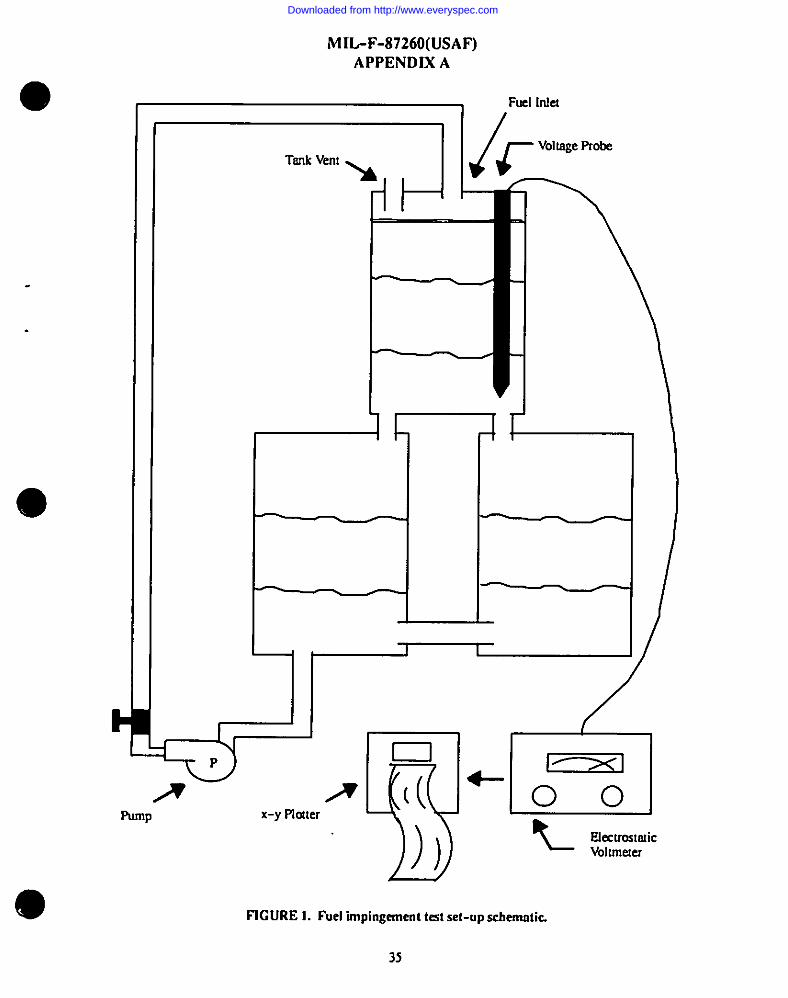
I
III
I1.I
1-
MIL-F-87260(USAF)APPENDIX A
Fuel MCI
TankVemh
d A
1
‘ f lfVoltage Probe
i
Punlp x-y Plcdter ql+n(( -00
h L ElectrctmticVoltnkxer
~
FIGURE 1. Fuel “mpingernent test set-up sehenmtic
35
Downloaded from http://www.everyspec.com
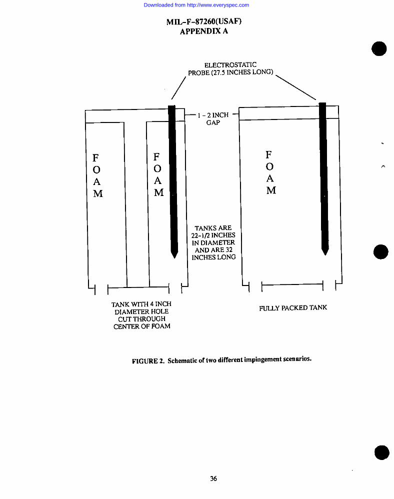
FoAM
it-
MIL-F-87260(USAF)
APPENDIX A
ELECTROSTATICPROBE (27.5lNCHES LONG)
/’ \
+
TANK WITH 4 INCHDIAMETER HOLE
CUT THROUGHCENTER OF FOAM
–l-21NcH -GAP
TANKS ARE22-1/2 INCHESIN DIAMETERAND ARE32
INCHES LONG
FoA
M
1FULLY PACKED TANK
FIGURE 2. Schematic of two different impingement scenarios.
36
.
Downloaded from http://www.everyspec.com
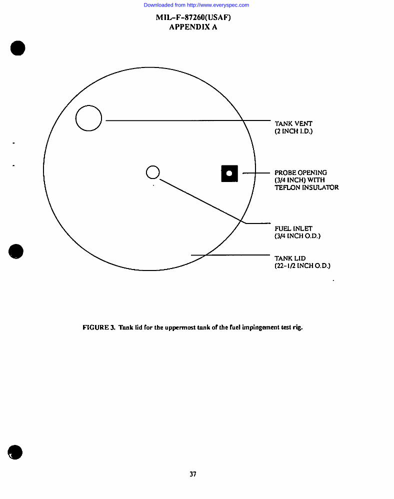
IMIL-F-87260(USA F)
APPENDIX A
!0
TANK VENT(2 [NCH I.D.)
“<o ❑ PROBE OPENING(3/4 INCH) WITHTEFLON INSULATOR
FUEL Iraxr(3/4 INCH O. D.)
TANK LID(22-1/2 INCH O. D.)
FIGURE 3. Tnnk lid for the uppennmt tank of the fuel impingement test rig.
37
Downloaded from http://www.everyspec.com
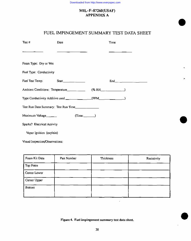
MIL-F-87260(USAF)APPENDIX A
FUEL Th4P[NGEMENT SUMMARY TEST DATA SHEET
Test# Date
Foam Type: Dry or Wet
Fuel Type: Conductivity
Fuel TesI Temp:
Ambient Conditions:
start
Temperature
Type Conductivity Additive used
Time
.End
(9o RH )
(PPM )
Test Run Data Summary: Test Run Time
Maximum Volmge_ (Time: _)
Sparks? Electrical Activity
Vapor Ignition (explain)
Visual InspectiorrjObservations:
Foam Kit Data Pan Number Thickness Resktivit y
Top Piece
Center Lower
Center Upper
Bottom
Pigure 4. Fuel impingement summary test data sheet.
38
Downloaded from http://www.everyspec.com
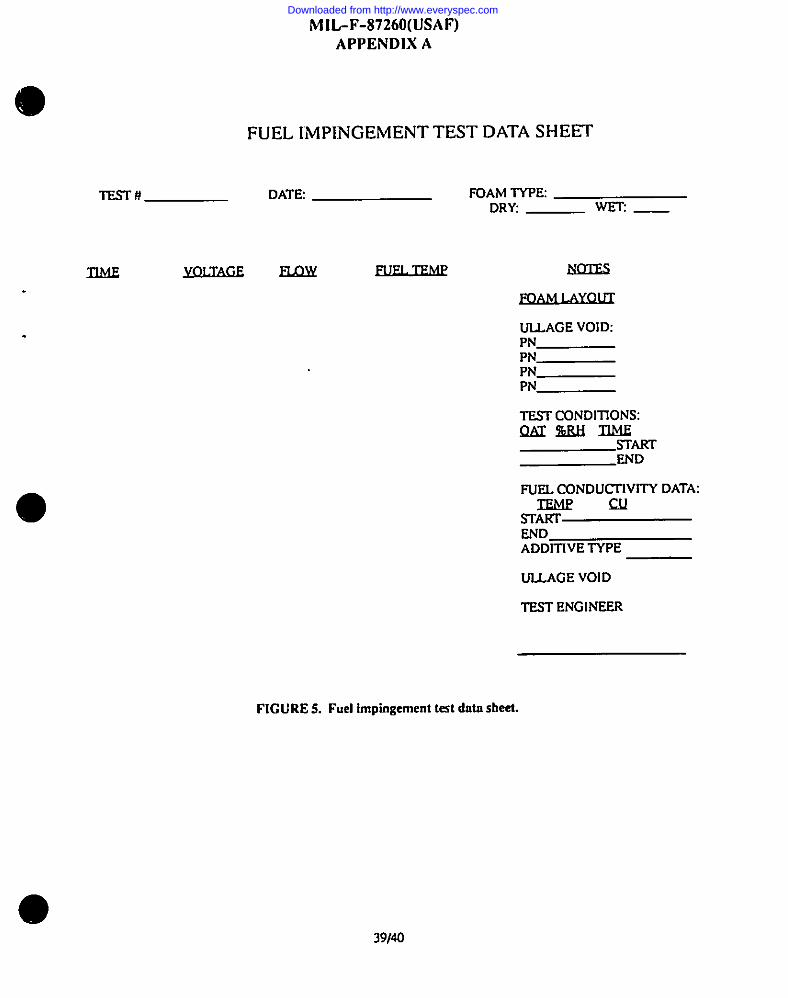
MIL-F-87260(USAF)APPENDIX A
FIGURE 5. Fuel impingement test data sheet.
‘o
FUEL lMP1lNGEMENT TEST DATA SHEET
lEsT# DATE FOAM TVPEDRY _ Wm _
mm YolmGEELmY
ULLAGE VOID:PNPNPNPN
TEST CONDITIONS:Qfsr%lUi TIME
srARTEND
FUEL CONDUITIVITY DATA:IEMf?CU
STARTENDADDITIVE TYPE
UUAGE VOID
TEST ENGINEER
I
I
39140
Downloaded from http://www.everyspec.com
.
MIL-F-87260(USAF)APPENDIX B
FLAMMABILfTYTEST FORTHE RATE OF BURNING ANDIOR EXTENT AND TIME OF
BURNING OF CELLULAR PLASTICS USfNG A SPECIMENSUPPORTED BY A HORIZONTAL SCREEN
10. SCOPE
10.1 Scope. This method covers a srnsll-stole horiscmml labormo1% screening procedure for mcnsuring the rme of
burning and/or exkm! and rime of burning of rigid or flexible celhdsr plastics in accordance tirJr this test prccedure.
10.2 Cnution. During tk course of combustion, gases or vapors, nreevolved which msy be hrzardmrsto p?rsmmel.Adequete prs$mnionsshmdd be orkento prmal the operaor.
20. APPLICABLE DOCUMENTS. This section is not applicable to tis qq!endix.
30. SIGNfFICANCE
30.1 Tess mnde oncelhdnrplestic rmdcrcondilions herein prescribedcsn be ofconsiderriion vsfue incompsrimg the mceof burning anrJ/or extmt snd time of burning of different msterinls, in controlling mmmfecturing praesses. or sc ameasure of deterioration or change in burmingcharacteristics prior to or during use
30.2 This method is not intended to be ncrimriom for tire hrmrd. ‘he tire hsmrd crmecl by msterish depends rcpmsh?form end end use of wc materisl. Assessment of tire hazard includes. bu! is not limited 10,msny fectors, such SS,east ofignition, burning rote, flame spreod, fuel contribution, imensit y of burning, and products of combustion.
40. APPARATUS
‘o 40.1 Test dumber. /my erdmure is snrisfocto~ that is Imgeessc.ughto provide quies draft-free sirermmd the sfxximm
during test, yet will permit normal thermsl circulation of sirpss! thespecimenduring burning. A hood is recmnnsendcd inorder to remove the sometimes noxious products of combustion. Ifatest chnrnberis used, i[shmdd Eeof such adesignchsrit crm be used in n Imd. For referee purpmm, test resuhs %’hhthe chamber shmdd be chesome whe!her or not tie hoodexhaust is on. bs cases of discrepancy, vrdues obtsined with the dsmper closed or the hood fen off, or both, will beconsidered valid.
40.1.1 Tfurecommcnded wtchmks~dkcomwcti ofshmt merel orotherfirc-rcsistem ms!erisl,hrwinginsidedimensimu303mm wide, @Omm long, rmd7@mmhigh, open at the top, witJsa ventilating opening approximstely25mm high around the bouom. A viewing window of hca!-re-sistmctglass shmdd be of stitcient size end in such a fmsiriontlsmriteentire length of the specimen under test may L!eobserved. llre chamber shmdd be reacfily opened sml clmed tof=ilimce mounting ml ignition of the test specimen.
40.2 Burner. A standard 9.5&3.5 mm cutsi& dismerer barrel Bunsen or Urn] burner fitted wirlra 48 *1 mm wide wing
[m. ~ ~ng @ ~Y Mve to bCOP=ed tO~ro~mmdy 3 ?3. 1 mm to provide the flsme required in 6.4.
40.3 Fuel supply. Propane gas of st Ienst 85 percent purity.
40.4Specimensuppcm.Wke cloti(wirescreen)6.Smm mesh using 0.8 mm diameter steel %’ir&Smirdess sml wirecloctrw be obtsined from Clevefend WweCloth snd Mfg. Co., 3573 E. 78th SI., Cfevelsnd, Ohio 44105. The wire clmhspecimen support 7S x 215 mmshall hovea IS ~1 mmof length kent to form a right engle. This will form thes~imen
suppms as shown on Figure 1.
40.5 Specimen suppmt holders. Any holding device that will clomp the wire cloth specimen suppmc horiamtally so chst
9
the kscrnomof the bent-up p.mien is 13*I mm above Utetop of the bumec wing mp, sc shown MSFigure 2. A typicelsrmngemem consists of two laboratory ring shreds with two tijuswble flnt surface clsmps which moy be Iccked in plsceby sa screw end lock run.
Downloaded from http://www.everyspec.com
MIL-F-87260(USAF)APPENDIX B
40.6 Sheet ofa$bestoskmrd. Ash&t ofmkstos bomd250x 250x6.5mm shdlbeplaced ontiebottom oftie lest
chamber. ●40.7 Aluminum fOil
40.8 Timing device, Accumteto*lsccond.
40.9 Measuring scale, Graduated in at least 2.0 mm intervals.
40.10 A device to ensure comet relative positioning of burner and specimen.
50. TEST SPECIMENS
50.1 Five specimens 50tO.25mm wide x 150+1 mm long shall be tested. .
50.1.1 Specimsnsshall be cut from representative material. Materials supplied inthickneasover 13 mm shell be cut to 13
mm Oickness. Materialsfoamedh thicknessesof13mm or less shall te tested at the thickness supplied.
50.1.2Materielswithdirectionaleffectssuchasskinorinsertsshallbaorienkdsoaatoprovidethemostadverseresdta.
50.1.3 Sheet sanrplcs shall be cut from a thickness of sheet nomrall y supplied or molded to a desired thickness
50.1.4 Molded expanded or sponge materials not conforming to the width requirements in 3.1 shall be tested as agreed
upon between the manufacturer end purchaser.
50.1.5 Each test specimen shall be marked across its width by one line 125 mm from one end.
60. CONDITIONING
60.1 Specimens drsll be preconditioned prior to test fora minimum of twohoura in the Iaboratow tat environment where●
the conditions of temperahuc and humidity are known.
70. PROCEDURE
70.1 Clamp the wire cloth specimen support horizontally so that the bottom of the wire cloth is 13 *I mm above the top of
the burner wing as shown on Figure 2. Cover the sheet of asbestos board with a layer of aluminum foil and place it on the
bottom of the test chrunber to catch any dripping or flaming particles. The distance between the wire cloth and the foil
shall be between 150 and 200 mm. Change the foil after each test, if there is any debris on the surface from the previous
determination. Bum off any materird remaining on the wire cloth from the previous tests, oruae a new wirecloti for each
test. If anew wire cloth is not used for each test, the wire cloth should be cool to the touch before being used. Ifdrippingormeltingma!eridfallintothewingtop,cleanhbeforetesting the next specimen.
70.2 Place the specimen on the support with one end touching Ihe 15 mm bmrt-up portion of the support. The end of thespecimen nearest the gage mark should be away fromthebent-upendof the spezimen support, so that the gage mark is125 mm away from the bent-up end.
70.3 Adjust the burner with the wing top to provide a blue flame whine visible portion is 38 *2 mm high with a clearly
defined inner cone 6.5 f 1.0 mm high sc shown on Figure 3. Placetheburner under the upturned end of the specimen
support so that one edge of the flame is in line with the upturnedend of the wire cloth end the other edge of Ure flrmre
extends into the front end of the specimen.
70.4 Stm’tthetimingdevice when the flame is first applied tothespecimen. After 60seconds, move the burner athxal 150
mm away from the test spmimen. Record the time in smonds when the flame front reaches the gage mark. if this dces notoccur, record the time in seconds for the flmrrefront to go out. If the flanre gcea out before reaching the gage mark, the o
42
Downloaded from http://www.everyspec.com
MIL-F-87260(USAF)APPENDIX B
.
.
extent of burning isetpml to 125mm minus thedismnce from Usegage mnrk lothenenrest evidence of the flame front, suchss sharring, along the upper surfme of the specimen measured 10Urenearest two mm. Note bumingchsmcteristics such asirmmsessence, melting, dripping, orsmodwring. Also record if the dripping carb foil bums. br some crises, the burningmay cease in lhe ticsl 60 setonds. ‘flis is evident by the disappearance of yellmv or chamsteristic flmrm
80.CALCULATIONS
SO.I ffthe flame front pssses lhe goge mork in any one of the five specimens, dresmrrple shafl & judged as burning. Thebunring rote is calculated by the following equstion:
A=;
w hew.
A. hming role, mmh,B. distance 10gqe msrk 125 mm, mrd
C = time for flame to reach gage mark, sec.
If only one specimen burns pas! tie gage mark. its bunsing rate shell be repmted, otherwise the avemge of the specimensthm bum past he gage mark shall ke reported.
SO.2 If the flame from does not reach the gage mork for nll five spximens, nvemge the kaursingtime in seconds rmdavemge the dismrrse burned in millimeters es measured M the lop surfscti
90. REPORT
90. I ~ mfxm (DI-MISC-90653) shall include M following:
90.1. I A descriptirm of the nsatensl including the density, the width end thickness, d mry prior rremmem orccmditioning end rhe presence or obsence of skin. If the specimen had skins, the repon shrill include whehec the skinsurfwe w= up or down.
90.1.2Smnp!etfm!burned 10the gage msrk. the burning rate in nsillimeters/secccnd.
90.1.3Forsmnplmthmdid not bum to the gage msrk, report the overage time of burning ad rhe average esmrrl ofburrring.
Esrmrple:
ATBXXX4EBXX_
Where
ATB. average [ime of burning. andAEB. m’emgeeskntofburning.
90.1.4A description of bucrsingchmacteristics such as melting, dripping or intumescence and wfsether dre dripping ormelting mmerials continued to bum WIthe ahmrinum foil.
10. PRECISION
IW. I Inteclabomtoiy rmmd-robm testing has esmblished h precision for each pscr of IIWtest ss follows
103.2 Reproducibility. The smmisrd deviotion for imerlabomtory reprmfuctibilily is:
For burning mtes N.08 mrrrlsscFor ATB A8.3 secFor AEB i9.9 mm
43
Downloaded from http://www.everyspec.com
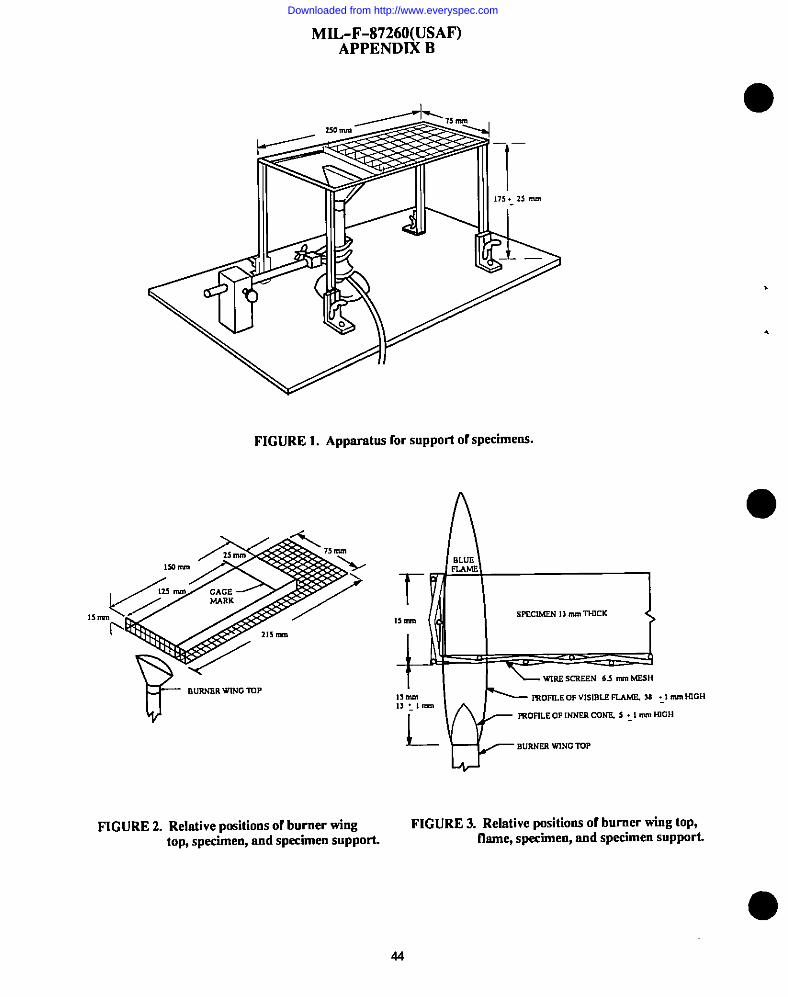
.
.
FIGURE 1. Apparatus for support of specimens.
<,,m
PI$mn
1$0m \
d m m (Mm
,,m / - /r 215rim
F’--/BURNERWtNGlVP
lsm
WR2 SCREEN 6S M MESH
1>m ~ rnOme OF VISUII.B FUMF. u :1 m tOCHl~:lm
l--
FROM.EOF INNER CONF. S :1 m wOH
BURNER wNG lUP
FIGURE 2. Relative pmitions of burner wing FIGURE 3. Relative positions of burner wing top,top, specimen, and specimen support. flame, specimen, and specimen support.
44
Downloaded from http://www.everyspec.com
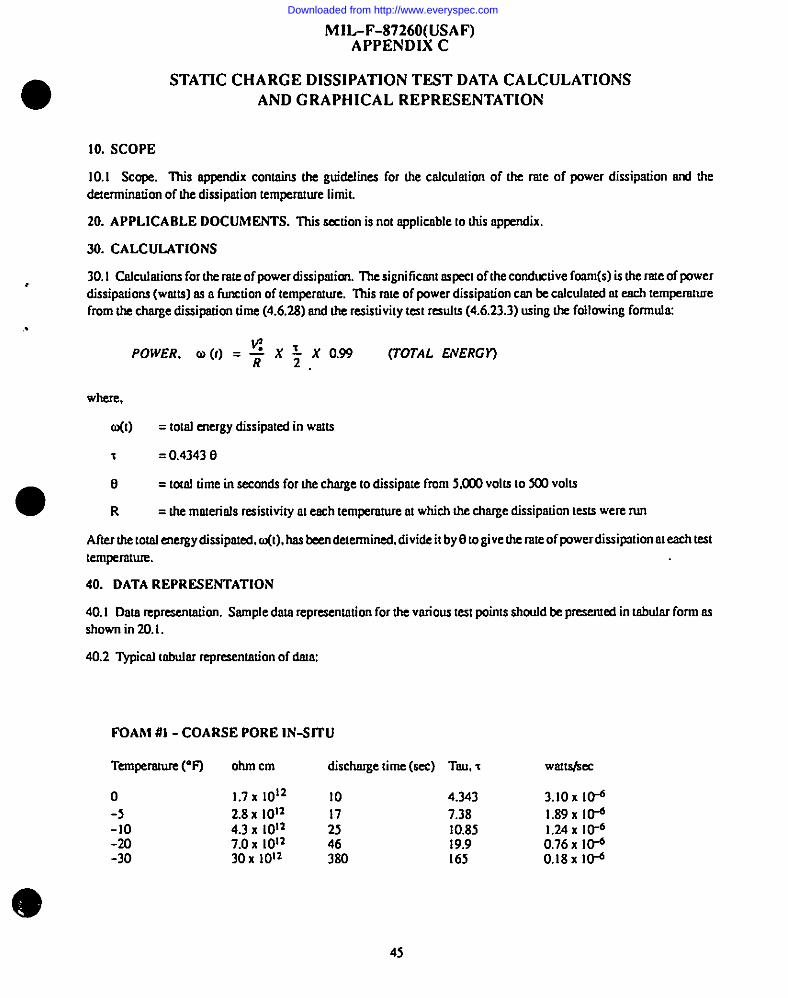
o
1“..
MIL-F-87260(USAF)APPENDIX C
STATIC CHARGE DISSIPATION TEST DATA CALCULATIONS
AND GRAPHICAL REPRESENTATION
10. SCOPE
10.1 Scope. l%is appcdix contains the guidelines for the cnlcuhnion of h rste of power dissipation ml thedemnninscion of the dissipation km~mt~e lhIIiL
20. APPLICABLE DOCUMENTS. This section is not npplicnbleto this appendix.
30. CALCULATIONS
30. I Cnlculstions for the rste of power dissipatim The signiticanl aipea of he conductive foam(s) is tie rate of powerdissipsdons (watts) ss a Iimction of temperature. his role of power dissipation can be cslcrdnted a each tempemnuefmm the chsrge dissipadon time (4.6.28) and h resistivity test msuhs (4.6.23.3) using the following fonnuhx
POWER, 0 (f) = # x $ x 0.99 (TOTAL ENERGY)
where,
o(t) = to:sl energy dissiptmedin wstfs
‘I = 0.43430
00 = LOUItime in saonds for the charge to dissipme from 5.003 volts 10X0 volts
R = he msmrhls resistivity n!emh tempemtureat which the chsrge dissipation Iests were nm
Afterthe totsl energy dissipated, m(t), has been determined, divide i! by Ll to give the rate of ~werdissipation al each test
lempemtum.
40. DATA REPRESENTATION
40.1 Dms rcprcsentodcm. Ssmple data reprcsentotion for the vmious tcsI points shcmfdbe pmsemed in tsbulsr form sc
shown in 20.1.
40.2 ~cal mbular represemacion of dam
FOAM #l - COARSE PORE lN-SfTU
Ternpsture (“F) ohm cm dischmge time (m) TIM I
o 1.7 x 10¹² 10 4.343
-5 2.8 X 10¹² 7.38-lo 4.3 x 10¹² : 10.85-20 7.OX 1012 46 I9.9-30 30X lol~ 380 165
wslLs/sec
3.IOX 10-61.89 X Id1.24 X 10-60.76 X [email protected] I@
4s
Downloaded from http://www.everyspec.com
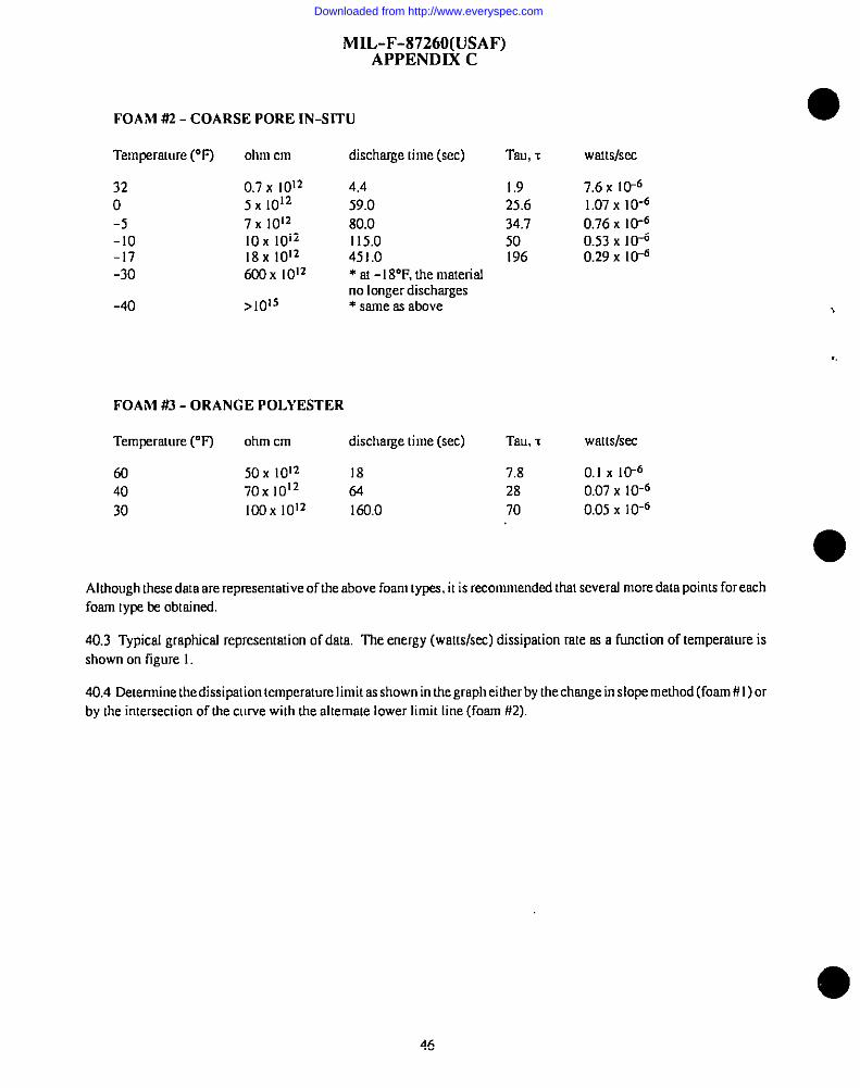
MIL-F-87260(USAF)APPENDIX C
FOAhl 4%2- COARSE PORE IN-SITU
Temperature (“F) ohm cm discharge time (see) Tau, ~ watts/see
32 0.7 x 10¹² 4.4 1.9 7.6 x lIFo 5X1OI2 59.0 25,6 1.07 X 10⁻⁶
-5 7X 10¹² 80.0 34.7 0.76 X l@-lo lox 1012 115,0 50 0.53 X 10⁻⁶-17 18x 1012 451.0 196 0.29 X 10⁻⁶-30 600 X 1012 * a - I8°F, the maerisJ
no longer dischwges-40 >1015 * same as above
FOAM #3 - ORANGE POLYESTER
Temperature ~F) ohm cm discharge time (see) Tau, T Waltslsec
60 50X 1012 18 7.8 0.1 X IIY6
40 70X 1012 64 28 0.07 X 10-630 IOOX1012 160.0 70 0.05 x 10⁻⁶
Although these data are representative of the above foam types, it is recommended that several more data points for eachfoam type be obtakd.
40.3 Typical graphical representation of data. The energy (watts/s&) dissipation rate as a function of temperature isshown on figure 1.
40,4 Determine the dissipation temperature limit as shown in the graph either by the chsnge in slope method (foam # I) 01by the intersection of the curve with the alternate lower limit line (foam #2).
46
Downloaded from http://www.everyspec.com
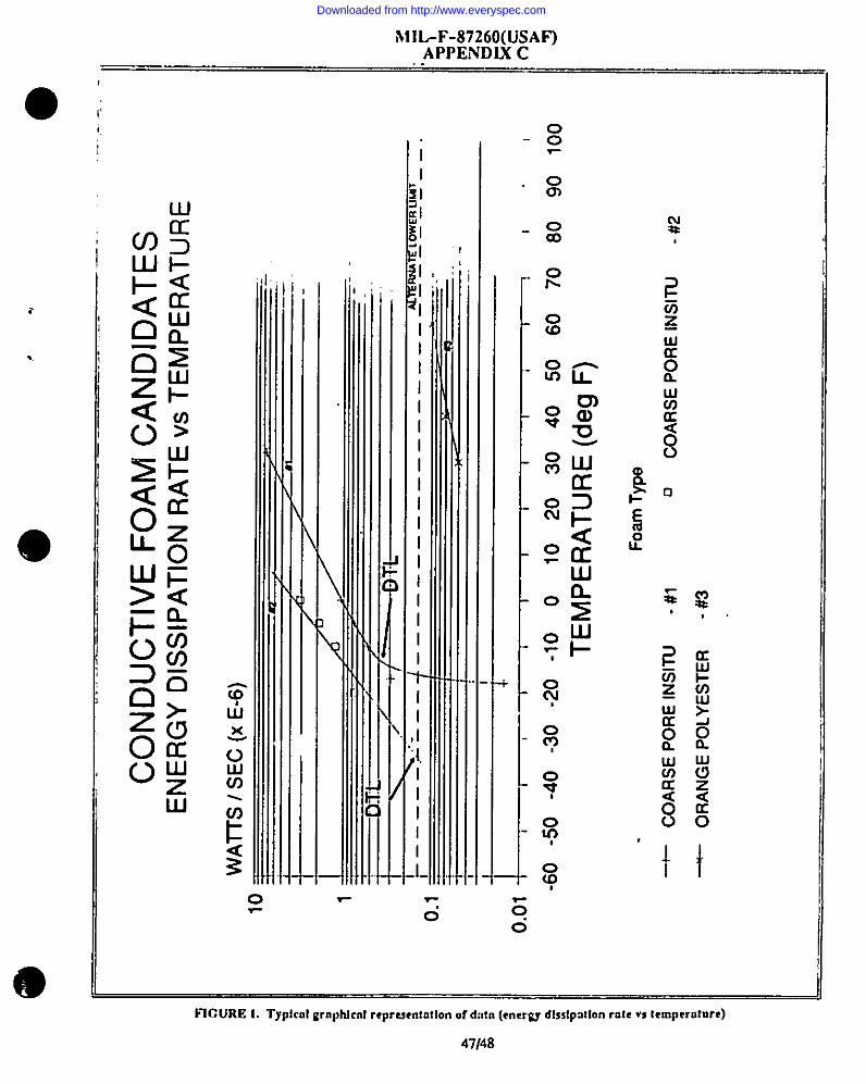
@e
,.,
●.
...
.—
CO
ND
UC
TIV
EF
OA
MC
AN
DID
AT
ES
EN
ER
GY
DIS
SIP
AT
ION
RA
TE
VS
TE
MP
ER
AT
UR
E
WA
ITS
/S
EC
(XE
-6)
10
——
—
I/6
--
-c.m
~I
\,/
~1-+
T+
..-—
——
——
.s—
——
4–––
–-––
––––
––––
____
”WW
5W%
”MT
---
o.
0.0
II
-.. .
—
1 &,,
li,I
II
II
I11
-60
-50
-40
-30
-Zo
-10
()10
2030
4050
6070
80
TE
MP
ER
AT
UR
E(d
egF
)
Fo
amT
ype
+C
OA
RS
EP
OR
EIN
SIT
U-
#1n
CO
AR
SE
PO
RE
INS
ITU
-#2
-O
RA
NG
EP
OL
YE
ST
ER
-#3
,, 9010
0
——
—-
—
Downloaded from http://www.everyspec.com
●
▼
STANDARDIZATION IXWIIMI?NT IMPROVF.Ml?NT PROPflSAI—--- . . . . . . . . . . . . . .— . ..-. . . . ..- .-- .._
lNSTRUCf70NS
1. The preparing sctivity must complete blosks 1, 2, 3. ocrd 8. In blcck 1, bafh fhe dosussrem number srsl revisimIesfershssdd be given.
2. ’31e subnrifcerof fhis form must complete blocks 4.5,6, snd 7.
3. The preparingtmivity must provide o reply wifhin 30 days fmm receipfof the form.
NOTE This form may not be used [o reques!copies of docunrenis.no! to requestwsivcxs, or cls.rilicafionof requirementscmcmremcmsfraas. Comnrenfssubmittedon this formdo notconstiftae or implyoufhorizntionto waive my pm’fiorrof the referenmddccumera(s]orto amendconuscnmsl requirenrems.
[ RECOMMEND A CHANGE1. tKKISMShT NUMBER Z DGCUMSNT DATE(YWMDDJ
3. oocuml-rrl.sFomn Mmerial, Esplosion Suppression. lnherenfly Elecuicslly Conductive, for Aircmff Fuel Tanksnd Dry Boy Areas
t. NATURS OF C?SANOE (ldmr~ Pqn@I numb am+indmfe ~qmsrd IZW,ik, (fp.uiMt. AULUhemu ,hr,u as nrcdd.)
;. SEASON mR SECD,UMSNDATION
SUBMSSTSSS
NAME (Saw.First bfi&f& MM) b. 01cOANSZA770N
ADDRSSS (/nc{wft~ Cd) d. TSU.SPHONE(lmti ,irm CdcJ 7. DATSsuasm-nzo(1)cmmmmml (Y7TfMDD)
(2) AU70VON((fapphclle)
FRSPARLVG AC17WTY
,. NAME B, lXLEFNONE(lnch@ ,4rra CO&J
ASDIENES (1) Cmmnmsd Cl) A7~7~; ;Japplkcblt)(513) 255-62S1
: AOORFSS (lmfu4 Z@ Cd,) W YOU DO NCf7SSCS!IVEA REFLY WTNIN 4SDAYS.CW4TA~ASDIENES ChfcnmOudifyc,ndStandodimtimoffs.
Wrighl-f%ferstm AFB, OH 4~3&6~3 S?0S lxecbq Pk. Suira1403.Fall,CSmmbVA22CM1-S4S4Td@mn (703)7S6-S340 AUllX’ON ZS9-WO
In l%- IA?< nr-r m -.. ,..- . ,,, ,,, 1.,4* “s , 07 m“,.”, ea,uall amm80u& 198/290
Downloaded from http://www.everyspec.com