Downhole Chemical Injection Devices and Related Equipment
118
Downhole Chemical Injection Devices and Related Equipment API SPECIFICATION 19CI FIRST EDITION, JUNE 2019 https://t.me/PrMaB
Transcript of Downhole Chemical Injection Devices and Related Equipment

Downhole Chemical Injection Devices and Related Equipment
API SPECIFICATION 19CIFIRST EDITION, JUNE 2019
https://t.me/PrMaB

Special Notes
API publications necessarily address problems of a general nature. With respect to particular circumstances, local, state, and federal laws and regulations should be reviewed.
Neither API nor any of API’s employees, subcontractors, consultants, committees, or other assignees make any warranty or representation, either express or implied, with respect to the accuracy, completeness, or usefulness of the information contained herein, or assume any liability or responsibility for any use, or the results of such use, of any information or process disclosed in this publication. Neither API nor any of API’s employees, subcontractors, consultants, or other assignees represent that use of this publication would not infringe upon privately owned rights.
API publications may be used by anyone desiring to do so. Every effort has been made by the Institute to assure the accuracy and reliability of the data contained in them; however, the Institute makes no representation, warranty, or guarantee in connection with this publication and hereby expressly disclaims any liability or responsibility for loss or damage resulting from its use or for the violation of any authorities having jurisdiction with which this publication may conflict.
API publications are published to facilitate the broad availability of proven, sound engineering and operating practices. These publications are not intended to obviate the need for applying sound engineering judgment regarding when and where these publications should be used. The formulation and publication of API publications is not intended in any way to inhibit anyone from using any other practices.
Any manufacturer marking equipment or materials in conformance with the marking requirements of an API standard is solely responsible for complying with all the applicable requirements of that standard. API does not represent, warrant, or guarantee that such products do in fact conform to the applicable API standard.
All rights reserved. No part of this work may be reproduced, translated, stored in a retrieval system, or transmitted by any means, electronic, mechanical, photocopying, recording, or otherwise, without prior written permission from the publisher.
Contact the Publisher, API Publishing Services, 200 Massachusetts Avenue, NW, Suite 1100, Washington, DC 20001-5571.
Copyright © 2019 American Petroleum Institute
ii
https://t.me/PrMaB

Foreword
Nothing contained in any API publication is to be construed as granting any right, by implication or otherwise, for the manufacture, sale, or use of any method, apparatus, or product covered by letters patent. Neither should anything contained in the publication be construed as insuring anyone against liability for infringement of letters patent.
The verbal forms used to express the provisions in this specification are as follows:
— the term “shall” denotes a minimum requirement to conform to the standard;
— the term “should” denotes a recommendation or that which is advised but not required to conform to the standard;
— the term “may” is used to express permission or a provision that is optional;
— the term “can” is used to express possibility or capability.
This document was produced under API standardization procedures that ensure appropriate notification and participation in the developmental process and is designated as an API standard. Questions concerning the interpretation of the content of this publication or comments and questions concerning the procedures under which this publication was developed should be directed in writing to the Director of Standards, American Petroleum Institute, 200 Massachusetts Avenue, NW, Suite 1100, Washington, DC 20001. Requests for permission to reproduce or translate all or any part of the material published herein should also be addressed to the director.
For API Monogram Program licensees and APIQR Program registrants, this standard shall become effective on the program date printed on the cover but may be used voluntarily from the date of publication.
Generally, API standards are reviewed and revised, reaffirmed, or withdrawn at least every 5 years. A one-time extension of up to 2 years may be added to this review cycle. Status of the publication can be ascertained from the API Standards Department, telephone (202) 682-8000. A catalog of API publications and materials is published annually by API, 200 Massachusetts Avenue, NW, Suite 1100, Washington, DC 20001.
Suggested revisions are invited and should be submitted to the Standards Department, API, 200 Massachusetts Avenue, NW, Suite 1100, Washington, DC 20001, [email protected].
iii
https://t.me/PrMaB

https://t.me/PrMaB

1 Scope ............................................................................................................................................................... 1
2 Normative References ...................................................................................................................................... 1
3 Terms, Definitions, Abbreviations, and Acronyms ............................................................................................ 33.1 Terms and Definitions ....................................................................................................................................... 33.2 Abbreviations and Acronyms .......................................................................................................................... 10
4 Functional Specification ................................................................................................................................. 114.1 General ........................................................................................................................................................... 114.2 Background .................................................................................................................................................... 114.3 Functional Characteristics .............................................................................................................................. 124.4 Well Parameters ............................................................................................................................................. 134.5 Operational Parameters ................................................................................................................................. 134.6 Fluid Cleanliness ............................................................................................................................................ 144.7 Compatibility with Well Equipment ................................................................................................................. 144.8 Design Validation Grades ............................................................................................................................... 144.9 Functional Testing Grades .............................................................................................................................. 154.10 Quality Levels ................................................................................................................................................. 164.11 Additional Testing/Evaluations ........................................................................................................................ 16
5 Technical Specifications ................................................................................................................................. 175.1 General Requirements ................................................................................................................................... 175.2 Chemical Injection Device Types .................................................................................................................... 175.3 Design Criteria ................................................................................................................................................ 175.4 Materials ......................................................................................................................................................... 195.5 Sealing System Requirements ....................................................................................................................... 215.6 Bonding Non-metallic Materials to Substrates ............................................................................................... 225.7 Design Verification .......................................................................................................................................... 225.8 Design Changes ............................................................................................................................................. 235.9 Design Validation Requirements .................................................................................................................... 235.10 Requirements for Annexes and Testing .......................................................................................................... 285.11 Special Features Validation ............................................................................................................................ 305.12 Unconventional Design Validations ................................................................................................................ 315.13 Retrievable Chemical Injection Designs ......................................................................................................... 315.14 Additional Design Validation Testing ............................................................................................................... 325.15 Scaling of Validated Designs .......................................................................................................................... 325.16 Functional Testing Requirements ................................................................................................................... 32
6 Supplier/Manufacturer Requirements ............................................................................................................. 336.1 General ........................................................................................................................................................... 336.2 Documentation and Data Control ................................................................................................................... 336.3 Identification ................................................................................................................................................... 356.4 Measuring and Testing Equipment ................................................................................................................. 356.5 Quality Requirements ..................................................................................................................................... 366.6 Materials Controls .......................................................................................................................................... 376.7 Non-destructive Examination Requirements .................................................................................................. 396.8 Sampling Requirements ................................................................................................................................. 416.9 Traceability ..................................................................................................................................................... 426.10 Manufacturing Non-conformance ................................................................................................................... 43
Contents
Page
v
https://t.me/PrMaB

7 Storage and Shipping Requirements ............................................................................................................. 437.1 General ........................................................................................................................................................... 437.2 Draining, Cleaning, and/or Drying .................................................................................................................. 437.3 Exterior Threaded Connections and External Seal Assemblies ..................................................................... 437.4 Permanent Marking ........................................................................................................................................ 437.5 Coatings for Transportation and Storage ....................................................................................................... 437.6 Shipping of Pressurized Chemical Injection Devices/Products ...................................................................... 44
8 Repair and Redress of Chemical Injection Devices/Products ........................................................................ 44
Annex A (informative) API Monogram Program Use of the API Monogram by Licensees ...................................... 45
Annex B (normative) Reverse Flow Prevention (RFP) Validation and Functional Testing ...................................... 49
Annex C (normative) Back Pressure Retention (BPR) Validation and Functional Testing ...................................... 64
Annex D (normative) Single-use Isolation Validation and Functional Testing Requirements .................................. 77
Annex E (normative) Secondary Chemical Injection Screen Validation and Functional Testing Requirements ...... 83
Annex F (normative) Retrievable Chemical Injection Device/Product Testing ......................................................... 87
Annex G (normative) Combination of Two or More Chemical Injection Devices into a Single Product ................... 91
Annex H (informative) Considerations for the Use of Chemical Injection Systems ................................................. 96
Bibliography ........................................................................................................................................................... 105
Figures
Tables
1 Summary of Chemical Injection Device Types ............................................................................................... 122 Device Design Validation Grade Summary .................................................................................................... 153 Product Design Validation Grade Summary ................................................................................................... 154 Device Functional Testing Grade Summary ................................................................................................... 165 Product Functional Testing Grade Summary .................................................................................................. 166 Quality Levels Summary ................................................................................................................................ 167 Device Validation Hierarchy ............................................................................................................................ 248 Product Validation Hierarchy .......................................................................................................................... 249 Metallic Material De-Rating Factor Examples ................................................................................................ 2610 Summary of Quality Requirements ................................................................................................................ 3611 Metallic Component Classification ................................................................................................................. 3712 Inspection Sample Size .................................................................................................................................. 42B.1 Reverse Flow Prevention (RFP) Validation Testing Series Summary ............................................................ 50
Contents
Page
vi
https://t.me/PrMaB

B.2 Reverse Flow Prevention (RFP) Functional Testing Summary ...................................................................... 61C.1 Back Pressure Retention (BPR) Validation Testing Summary ........................................................................ 65C.2 Completion Actions for V3, V2, and V1 Validation .......................................................................................... 67C.3 Back Pressure Retention (BPR) Functional Testing Summary ....................................................................... 73D.1 Single-use Isolation (SUI) Validation Testing Summary ................................................................................. 78D.2 Single-use Isolation (SUI) Functional Testing Summary ................................................................................ 81E.1 Secondary Chemical Injection Screen (SCIS) Validation Testing Summary .................................................. 84F.1 Retrievable Validation Testing Summary ........................................................................................................ 88G.1 Combined Product Validation Summary—Individually Validated Devices ...................................................... 92G.2 Combined Product Validation Summary—Unvalidated Device(s) .................................................................. 93G.3 Combined Products Functional Testing Summary .......................................................................................... 95
Contents
Page
vii
https://t.me/PrMaB

https://t.me/PrMaB

Introduction
This specification has been developed by users/purchasers and suppliers/manufacturers of downhole chemical injection devices/products that are used in side-pocket mandrels and tubing retrievable mandrels/carriers in the worldwide petroleum and natural gas industry. This specification is intended to provide requirements and information to parties who are involved in the specification, selection, manufacture, testing and use of chemical injection devices. Further, this specification contains the minimum supplier/manufacturer requirements to claim conformity to this specification.
This specification has been structured to support a range of requirements in design verification, design validation, functional testing, and quality. These variations allow the user/purchaser to select the grades and levels for a specific application.
There are four design validation grades for chemical injection devices and four for products that provide the user/purchaser with a range of technical requirements and ratings. This ensures that the devices/products supplied according to this specification meet the requirements and that the user/purchaser can compare these requirements with its preference or application and determine whether additional requirements are placed on the supplier/manufacturer.
It is important that users of this specification are aware that requirements in addition to those outlined herein may be needed for individual applications. This specification is not intended to inhibit a supplier/manufacturer from offering, or the user/purchaser from accepting, alternative equipment or engineering solutions. This can be particularly applicable where there is innovative or developing technology. Where an alternative is offered, it is the responsibility of the supplier/manufacturer to identify variations from this specification and provide details.
Two quality levels are provided that the user/purchaser may choose to meet specific preferences or applications. Additional quality requirements can be specified by the user/purchaser as supplemental requirements.
In addition to the requirements of this document, related requirements are included in the following:
— API 19G1 provides requirements for side-pocket mandrels;
— API 19G3 provides requirements for running, pulling, kick-over tools and latches used in conjunction with side-pocket mandrel chemical injection devices/products;
— API 19G4 provides requirements for side-pocket mandrels and related equipment;
— API 19AC provides requirements for mandrels or carriers that are used with chemical injection devices/products when installed in a well.
ix
https://t.me/PrMaB

https://t.me/PrMaB

Downhole Chemical Injection Devices and Related Equipment
1 Scope
This specification provides requirements for chemical injection devices intended for use in the worldwide petroleum and natural gas industry. This includes requirements for specifying, selecting, design verification, validation testing, manufacturing, quality-control, testing, and preparation for shipping of chemical injection devices as defined herein. These requirements include in-line debris screen systems, single-use shearable/frangible devices, and performance testing and calibration procedures.
The installation and retrieval of chemical Injection devices and systems is outside the scope of this document (see API 19G2 and API 19G3).
This document does not include requirements for mandrels, carriers, running, pulling, and kick-over tools, handling tools and latches, injection lines, fittings, control line connectors, clamps, chemicals and chemical delivery systems. Service, repair or redress of used chemical Injection devices is outside of the scope of this document.
Validation and functional testing within this specification is performed using water as the testing medium. Design validation in conformance with this specification may not provide assurance that a chemical injection device/product will perform in a specific well, due to the variety and potential contamination of the injected chemicals.
Included in this specification are Annex B through Annex G (normative) and Annex A and Annex H (informative). If a product is supplied bearing the API Monogram and manufactured at a facility licensed by API, the provisions of Annex A apply.
2 Normative References
The following referenced documents are referred to in the text in such a way that some or all the content constitutes requirements of this document. For dated references, only the edition cited applies. For undated references, the latest edition of the referenced document (including amendments) applies.
API Specification 5B, Specification for Threading, Gauging and Thread Inspection of Casing, Tubing, and Line Pipe Threads
API Specification 7-2, Specification for Threading and Gauging of Rotary Shouldered Thread Connections, Second Edition
API Specification 19G1, Side-pocket Mandrels
API Specification 19G2, Flow-control Devices for Side Pocket Mandrels
API Specification 19G3, Running Tools, Pulling Tools, and Kick-over Tools and Latches for Side-Pocket Mandrels
API Recommended Practice 19G4, Practices for Side-pocket Mandrels and Related Equipment
API Q1, Quality Management System Requirements for Manufacturing Organizations for the Petroleum and Natural Gas Industry
ASME 1 Boiler and Pressure Vessel Code (BPVC), Section V, Nondestructive Examination
1 American Society of Mechanical Engineers, 345 East 47th Street, New York, NY 10017-2392, USA, www.asme.org.
1
https://t.me/PrMaB

ASNT 2 Recommended Practice SNT-TC-1A, Personnel Qualification and Certification in Non-destructive Testing - 2016 Edition
ASQ 3 Z1.4, Sampling Procedures and Tables for Inspection by Attributes
ASTM 4 E10, Standard Test Method for Brinell Hardness of Metallic Materials
ASTM E18, Standard Test Methods for Rockwell Hardness of Metallic Materials
ASTM E110, Standard Test Method for Rockwell and Brinell Hardness of Metallic Materials by Portable Hardness Testers
ASTM E165, Standard Practice for Liquid Penetrant Examination for General Industry
ASTM E213, Standard Practice for Ultrasonic Testing of Metal Pipe and Tubing
ASTM A388/A388M, Standard Practice for Ultrasonic Examination of Steel Forging
ASTM E428, Standard Practice for Fabrication and Control of Metal, Other than Aluminum, Reference Blocks Used in Ultrasonic Testing
ASTM E709, Standard Guide for Magnetic Particle Testing
ASQ H1331, Zero Acceptance Number Sampling Plans
ISO 5 2859-1, Sampling procedures for inspection by attributes - Part 1: Sampling schemes indexed by acceptance quality limit (AQL) for lot-by-lot inspection
ISO 3601-1, Fluid power systems - O-rings - Part 1: Inside diameters, cross-sections, tolerances and designation codes
ISO 3601-3, Fluid power systems—O-Rings—Part 3: Quality acceptance criteria
ISO 6506 (all parts), Metallic materials—Brinell hardness test
ISO 6507 (all parts), Metallic materials—Vickers hardness test
ISO 6508 (all parts), Metallic materials—Rockwell hardness test
ISO 9712, Non-destructive testing—Qualification and certification of NDT personnel
ISO 17025, General requirements for the competence of testing and calibration laboratories
ISO 13665, Seamless and Welded Steel Tubes for Pressure Purposes—Magnetic Particle Inspection of the Tube Body for the Detection of Surface Imperfections
ISO 23936-1, Petroleum, petrochemical and natural gas industries—Non-metallic materials in contact with media related to oil and gas production—Part 1: Thermoplastics
2 American Society for Nondestructive Testing, 1711 Arlingate Lane, Columbus, OH 43228-0518, USA, www.asnt.org.
3 American Society for Quality, 600 North Plankinton Avenue, Milwaukee, WI 53203, USA, www.asq.org.4 ASTM International, 100 Barr Harbor Drive, West Conshohocken, PA 19428-2959, USA, www.astm.org.5 International Organization for Standardization, Chemin de Blandonnet 8, CP 401-1214 Vernier, Geneva,
Switzerland, www.iso.org.
API SPecIfIcAtIon 19cI2
https://t.me/PrMaB

ISO 23936-2, Petroleum, petrochemical and natural gas industries—Non-metallic materials in contact with media related to oil and gas production—Part 2: Elastomers
SAE 6 AS 568A, Aerospace Size Standard for O-Rings
NACE 7 MR0175/ISO 15156 (all parts), Petroleum and natural gas industries—Materials for use in H2S-containing environments in oil and gas devices
3 Terms,Definitions,Abbreviations,andAcronyms
For the purposes of this document, the terms and definitions given in API Q1 (for quality-system-related terms not given below) and the following apply.
3.1 TermsandDefinitions
3.1.1ambient temperaturePrevailing temperature at the testing facility.
3.1.2back check testBCTStatic pressure test conducted where pressure is applied to a non-return (check) valve in the reverse direction to normal forward flow.
3.1.3back pressurePressure opposing forward flow.
3.1.4back pressure retentionBPRA device providing back pressure support (U-tube prevention) to prevent hydrostatic-fall-through of fluids while allowing flow to a defined outlet.
3.1.5certificateofconformanceDocument in which the supplier/manufacturer certifies that the product or service is in conformance to the referenced standards, specifications, and requirements.
3.1.6chemicaldeliverysystemA system above the tubing hanger designed to supply the controlled delivery of chemicals into a well.
3.1.7chemical injection device/productA downhole, below-the-tubing-hanger device that controls the flow of chemical(s) into a well.
3.1.8chemicalsFluids injected into the well via a chemical injection system.
6 SAE International, 400 Commonwealth Drive, Warrendale, PA 15096, USA, www.sae.org.7 NACE International, 15835 Park Ten Place, Houston, Texas 77084, USA, www.nace.org.
Downhole chemIcAl InjectIon DevIceS AnD RelAteD equIPment 3
https://t.me/PrMaB

3.1.9cleanlinessA measured value of contaminants within a fluid.
3.1.10closing pressurePressure at which forward flow through a device stops
3.1.11completion loadA load or combination of loads that affects the function or integrity of a chemical injection device/product.
NOTE Loads can include one or more of the following:
— internal and external tubing or casing pressures;
— axial compression or tensile loadings;
— bending loads from dog legs/well deviations.
3.1.12crack-open pressureThe pressure at which flow of the fluid is initiated in the flow direction as injection pressure is increased.
3.1.13design validationProcess of proving a design by testing to demonstrate conformity of the product to design requirements.
NOTE Design validation can include one or more of the following (this is not an all-inclusive list):
— prototype tests;
— functional or operational tests of production products, or both;
— tests specified by industry standards or regulatory requirements, or both;
— field performance tests and reviews.
3.1.14designverificationProcess of examining the result of a design and development output to determine conformity with specified requirements.
NOTE Design verification activities can include one or more of the following (this is not an all-inclusive list):
a) confirming the accuracy of design results through the performance of alternative calculations;
b) review of design output documents independent of activities of design and development;
c) comparing new designs to similar proven designs.
3.1.15deviceComponent or subassembly which provides a function defined in Table 6.
API SPecIfIcAtIon 19cI4
https://t.me/PrMaB

3.1.16end connectionThread or other mechanism providing a connection between the chemical injection device/product and other equipment.
3.1.17externalsealassemblySealing mechanism used to seal the exterior of a retrievable chemical injection device/product when installed in its defined mandrel.
3.1.18external test pressureDifferential test pressure between the applied external pressure and internal pressure at which a product is tested for collapse resistance.
3.1.19failure pressureThe pressure that causes the component or device/product to fail.
3.1.20flowcharacterizationA numerical and/or graphical representation of a device’s pressure behavior through a range of flow rates.
3.1.21forwardflowThe path of movement in which the valve’s open position is the non-restrictive conduit point of injection.
3.1.22forwardflowingpressureThe pressure which results in flow moving in the forward direction through a pressure control device.
3.1.23free passageAbility of a device to pass through a geometric space of a defined size without impact loading.
3.1.24functionalspecificationUser/purchaser prepared requirements for chemical injection device/product which include the well parameters, operational parameters and environment, or the identification of the supplier/manufacturer’s specific device/product.
3.1.25functional testTest performed to confirm proper operation of device/product.
3.1.26heatA particular batch of metal to which a raw material mill assigns a unique identification number called a heat number.
3.1.27hydrostaticfall-throughThe condition where the applied hydrostatic in a fluid conduit is greater than the pressure present in the fluid in the delivery conduit falling (U-tube effect).
Downhole chemIcAl InjectIon DevIceS AnD RelAteD equIPment 5
https://t.me/PrMaB

3.1.28informativeInformation that is meant to inform the user/purchaser or supplier/manufacturer without containing requirements.
3.1.29injection linePressure-retaining conduit within a well which can deliver fluid from the tubing hanger to the injection point/device.
3.1.30screenA device in the chemical injection flow path which restricts installation debris flow which may include a bypass and does not function as a flow regulating component.
3.1.31internal test pressureDifferential test pressure between the applied internal pressure and external pressure at which a product is tested for burst resistance.
3.1.32job lotA collection or quantity of piece parts, subassemblies or assemblies that are processed together during the manufacturing process.
3.1.33kickover toolWireline deployed tool used to selectively install and retrieve latch-mounted devices in side-pocket mandrels.
3.1.34latchRetention mechanism for a chemical injection device/product that is installed in a side-pocket mandrel.
3.1.35legacydeviceA design provided by the supplier/manufacturer before the publication of this specification.
3.1.36mandrelcarrierA well completion component, to which a chemical injection device/product is assembled, at which chemicals may be injected into the well.
3.1.37manufacturingProcess(es) performed by an equipment supplier/manufacturer that are necessary to provide a finished component(s) or assembly(ies).
3.1.38material substitutionThe allowance of materials different than those used when validating adevice/product without additional validation testing.
3.1.39maximumflowrateThe greatest flow rate at which the injection device/product conforms to the design performance rating.
API SPecIfIcAtIon 19cI6
https://t.me/PrMaB
3.1.40maximum rated temperatureThe greatest temperature for which the device/product is designed.
3.1.41millcertificateQuality control documentation of a component’s raw material, certifying its chemical composition, physical properties, and mechanical properties.
3.1.42minimumflowrateThe lowest flow rate at which the injection device/product conforms to the design performance rating.
3.1.43minimum rated temperatureThe lowest temperature for which the device/product is designed.
3.1.44modelDevices/products with unique components and functional characteristics that differentiate them from other devices/products of the same type.
3.1.45normativeInformation or procedures that are mandatory for use by the user/purchaser or supplier/manufacturer.
3.1.46opening pressurePressure required to open the closure mechanism where the flow dynamics are acceptable.
3.1.47operating environmentSet of environmental conditions to which the device is exposed during its service life.
NOTE This includes such environmental variables as temperature, pressure, liquid composition and properties, gas composition and properties, solids, etc.
3.1.48pocketParallel bore, including sealing surfaces and latching profiles that is offset from and essentially parallel with the through-bore of the side-pocket mandrel.
3.1.49productAn assembly of two or more chemical injection devices (as defined in Table 6) which are designed to function as a single unit.
3.1.50functional testing gradeCategory with a defined range of processes, method(s) and/or test(s) that are used by the supplier/manufacturer to demonstrate that a particular device has been manufactured to meet the requirements for that device.
3.1.51pulling toolDevice used to retrieve a latch mounted device from a side-pocket mandrel, normally with the use of a kickover tool.
Downhole chemIcAl InjectIon DevIceS AnD RelAteD equIPment 7
https://t.me/PrMaB

3.1.52qualifiedpersonAn individual with characteristics or abilities gained through training or experience or both; as measured against established requirements such as standards or tests that enable the individual to perform a required function effectively.
3.1.53rated pressureMaximum differential pressure at a defined temperature for which the chemical injection device/product is designed.
3.1.54rated temperature rangeThe range of temperatures from minimum rated temperature to maximum rated temperature.
3.1.55redressAny activity involving the replacement of parts within the limits of the device’s operating manual.
3.1.56repairActivity that includes disassembly, reassembly and testing with or without the replacement of qualified parts and can include machining, welding, heat treating or other manufacturing operations that restores the equipment to its original performance.
3.1.57retrievable chemical injection deviceA chemical injection device that is run, secured in, and retrieved from a side pocket mandrel by wireline or other means.
3.1.58reverseflowpreventionRFPA device (reverse flow check) that allows unidirectional flow from a supply to a defined outlet; the device will affect a seal in the reverse direction by way of an internal actuation mechanism.
3.1.59running toolsDevice used to deploy latch mounted products into side pocket mandrel, normally combined with the use of a kickover tool.
3.1.60scalingValidating a design by referencing the validation conducted on a device of the same design family.
3.1.61secondarychemicalinjectionscreenSCISA device in the chemical injection flow path that restricts installation debris flow and may include a bypass and does not function as a flow regulating component.
3.1.62secondarychemicalinjectionscreen(SCIS)elementComponent that prevents the flow of particles of a defined size.
API SPecIfIcAtIon 19cI8
https://t.me/PrMaB

3.1.63secondarychemicalinjectionscreen(SCIS)housingThe component of the secondary chemical injection screen device that provides the physical structure that retains the element and contains the flowing pressure.
3.1.64shearable/frangible deviceA device which changes flow dynamics after activation once a differential pressure or other defined load is applied.
3.1.65shear-outAction of a single-use isolation device (SUI) when a defined differential pressure or other defined loading is applied.
3.1.66side-pocket mandrelA well completion component with a bore or pocket that 1) is offset from the through-bore of the production tubing and 2) houses a chemical injection device/product.
NOTE This bore includes sealing surfaces and latching profiles.
3.1.67single-use isolationSUIA device in the flow path that is initially closed; once it is opened, it cannot be reclosed and does not function as a pressure or flow control component.
3.1.68sour serviceExposure to oilfied enviornments that contain H2S and can cause cracking of materials by the mechanisms addressed in NACE MR0175.
3.1.69special featureA specific functional capability or subassembly which is not validated in the defined validation testing sequences.
3.1.70substantive design changeA design change identified by a qualified person that affects the performance of a device/product in comparision to the other device/product qualified in accordance with this specification.
3.1.71supplier/manufacturerCompany, organization, or entity that designs and manufactures chemical injection devices/products.
3.1.72technicalspecificationRequirements of the equipment necessary for compliance with the functional specification.
3.1.73test pressurePressure applied as specified by the pertinent test procedure.
NOTE Each test pressure has a related test temperature.
Downhole chemIcAl InjectIon DevIceS AnD RelAteD equIPment 9
https://t.me/PrMaB

3.1.74test temperatureTemperature based on relevant design criteria, at which the equipment is tested.
3.1.75total closureThe state at which there is no flow through the device.
3.1.76traceabilityAbility for individual components to be designated as originating from a job lot that identifies the included heat number(s).
3.1.77tubing reelA length of conduit (injection line) of a specified diameter and length typically provided on a cylindrical reel.
3.1.78typeChemical injection device/product with unique characteristics that perform a specific function.
3.1.79unconventional designA chemical injection device or product design that performs one or more functions defined in Table 1 that is not fully compatible with the required validation testing criteria.
3.1.80user/purchaserCompany, organization, or entity that purchases, installs and uses chemical injection devices.
3.1.81U-tube effectThe hydrodynamic phenomenon of fluid reaching equilibrium and balance in height through their equalization of fluid hydrostatics.
3.1.82weldingMethod for joining two metallic substances through a process of melting and re-solidification.
NOTE Includes brazing and soldering.
3.1.83wirelineA general term referring to oil and gas well intervention operations in which a single-strand or multistrand wire or cable is used to install and retrieve flow control devices.
3.1.84yieldstrengthStress level measured at test temperature, beyond which material plastically deforms and does not return to its original dimensions.
NOTE Yield strength is expressed in units of force per unit of area.
3.2 AbbreviationsandAcronyms
AOQL average outgoing quality limit
API SPecIfIcAtIon 19cI10
https://t.me/PrMaB

BCT back check test
BPR back pressure retention
COC certificate of conformance
ID internal diameter
ISO International Organization for Standardization
MTR material test report
NACE National Association of Corrosion Engineers
NDE non-destructive examination
OD outside diameter
PQR procedure qualification record
QMS quality management system
RA risk assessment
RFP reverse flow prevention
RIH run in hole
ROV remotely operated vehicle
RP recommended practice
SAE Society of Automotive Engineers
SCIS secondary chemical injection screen
SPM side pocket mandrel
SUI single-use isolation device
WPQ welder/welding operator performance qualification
WPS welding procedure specification
4 FunctionalSpecification
4.1 General
The purpose of the functional specification is to allow the user/purchaser to specify and define the functional requirements for chemical injection devices/products.
The user/purchaser should prepare a functional specification for devices/products that conform to this specification. The specification should contain the requirements of this section and the operating conditions, as appropriate, and/or identify the supplier/manufacturer’s specific device. These requirements and operating conditions may be conveyed by means of a dimensional drawing, a data sheet, a functional specification form or other suitable documentation.
4.2 Background
Chemical injection is the process of injecting fluid chemicals into a well to control corrosion and harmful deposits in the tubing and tubing accessories during production. In a typical chemical injection installation, a chemical injection mandrel with a chemical injection valve is installed as part of the tubing string.
A chemical injection line can be run from the chemical injection mandrel to the surface to act as a conduit for the chemicals. In other installations, the chemicals are pumped down the tubing/casing annulus and into a port in the chemical injection mandrel.
Downhole chemIcAl InjectIon DevIceS AnD RelAteD equIPment 11
https://t.me/PrMaB

Reverse flow prevention (RFP) devices are installed at the point of injection to prevent flow from the production tubing from entering the injection-flow path. A high-pressure pump, capable of overcoming tubing pressure, is installed on the surface to pump the chemicals into the downhole point of injection in the production stream.
Further explanation of chemical injection is in Annex H.
4.3 Functional Characteristics
4.3.1 General
The chemical injection device/product acts to control the flow or communication of gas and/or liquid between the pressure-retaining areas of the well. The user/purchaser shall specify and select the following functional characteristics, as applicable.
4.3.2 Functions
The user/purchaser may specify a specific chemical injection device/product, one device in Table 1, or a combination of the devices in Table 1.
Table1—SummaryofChemicalInjectionDeviceTypes
DeviceTypeAbbreviation
DeviceTypeName FunctionalDefinition Applicable
Annex
RFP Reverse flow prevention
A device that allows unidirectional flow from a supply to a defined outlet. The device will affect a seal in the reverse direction by way of an internal actuation mechanism.
B
BPR Back pressure retention
A device providing back pressure support (U-tube prevention) to prevent hydrostatic-fall-through of fluids while allowing flow to a defined outlet.
C
SUI Single-use isolation
A pressure activated device in the flow path or a line block that is initially closed; once it is opened, it cannot be reclosed and does not function as a pressure or flow control component.
D
SCISSecondary chemical injection screen
A device in the chemical injection flow path which restricts installation debris flow and which may or may not include a bypass, and does not function as a flow regulating component.
E
4.3.3 Retrievable Designs
Retrievable designs shall include the following:
a) Nominal chemical injection device/product size, e.g. 25.4 mm (1 in.), or 38.1 mm (1.5 in.), etc.
b) Latch (retention mechanism) type for installing, securing, and retrieving the chemical injection device/product in a side-pocket mandrel.
c) Seal bore nominal size and configuration to house the chemical injection device/product or the side-pocket mandrel model.
d) Either the location and configuration of the inlet and outlet ports of the chemical injection device/product or the model of the chemical injection device/product.
e) Conduit ports, connection size, and configuration for side-pocket mandrel external ports and outlets to which a side-string, control line, or injection conduit connects.
f) Description of the mandrel; see 5.2.
API SPecIfIcAtIon 19cI12
https://t.me/PrMaB

4.4 Well Parameters
4.4.1 Well Fluid Parameters
The following well fluid parameters to which the chemical injection device/product is exposed should be provided by the user/purchaser.
a) Fluid composition, specific gravity, etc. of the following:
— produced fluids (e.g. liquid, hydrocarbon gas, CO2, H2S);
— injection gas (e.g. hydrocarbon gas, CO2, etc.);
— injection fluids (e.g. water, steam, CO2, chemicals, oxygen content, etc.);
— completion fluids;
— treatment/stimulation fluids/chemicals.
b) Description of extraneous components (e.g. paraffin, sand, scale, corrosion products, etc.).
4.4.2 Well Operations
Expected well intervention(s)/operation(s) including the parameters, such as those below, should be provided by the user/purchaser.
a) acidizing, including acid composition, pressure, temperature, acidizing velocity, exposure time, and other chemicals used during well stimulation;
b) fracturing, including proppant description, fracture fluid velocity, proppant/fluid ratio;
c) sand consolidation operations.
4.4.3 EnvironmentalCompatibility
If the user/purchaser has access to the corrosion property data of the operating environment based on historical data and/or research, this information may be made available to the supplier/manufacturer. The user/purchaser may indicate to the supplier/manufacturer which material(s) have the ability to perform as required within the subject well’s corrosion environment.
4.5 Operational Parameters
The user/purchaser should specify installation, testing, and operational parameters as applicable.
a) chemical injection depth;
b) topside injection system maximum pressure rating;
c) chemical properties, e.g. specific gravity, viscosity;
d) minimum and maximum chemical flow rates;
e) temperature gradients;
f) pressure range at the point of injection at the device/product outlet;
g) operating pressure range of the device/product;
Downhole chemIcAl InjectIon DevIceS AnD RelAteD equIPment 13
https://t.me/PrMaB

h) operating temperature range of the device/product;
i) maximum differential pressure across the chemical injection device/product;
j) pressure differential at which a SUI opens;
k) installation; testing and operational procedures;
l) deployment and retrieval method(s);
m) injection line length, size, and ratings.
4.6 Fluid Cleanliness
Devices/products from different suppliers/manufacturers and of different functional types may operate with injected fluids of varying cleanliness. It is, therefore, impractical to specify fluid cleanliness. See Annex H for system design guidelines.
4.7 CompatibilitywithWellEquipment
The user/purchaser, where applicable, shall specify the end connection designs and material requirements, free-passage requirements and external/internal dimensional limitations needed to ensure that the device/product conforms to the application.
An example list follows:
a) size, type, material, configuration and dimensions of the end connection between the device/product and other well equipment;
b) internal/external receptacle profile(s)/securing mechanism(s), sealing dimensions and their respective locations.
API 19G1 details the sealing bore dimensions required for side-pocket mandrels specifications. The retrievable chemical injection devices/products should be selected to match the dimensions in accordance with API 19G1. If there are occasions when the design of the side-pocket mandrel requires sealing bore dimensions other than those listed, the agreement between the user/purchaser and supplier/manufacturer shall be documented.
4.8 Design Validation Grades
4.8.1 General
The user/purchaser should specify one of the following design validation grades for each chemical injection device or alternately for each product design. If no design validation grade is specified, Grade V2 or CV2 shall be provided.
4.8.2 Device Design Validation Grades
This specification provides four design validation grades as shown in Table 2.
API SPecIfIcAtIon 19cI14
https://t.me/PrMaB

Table2—DeviceDesignValidationGradeSummary
Grade Description Requirements
V4 Minimum grade of device validation
Supplier/manufacturer defined requirements with engineering validation documentation of the defined ratings and capabilities.
V3 Reduced grade of device validation
V3 (applicable to BPR/RFP only) requires validation of a single copy of the design with water. Validation includes testing for the designated functions with reduced repetition of the testing steps. See Annex B and Annex C.
V2 Intermediate grade of device validation
V2 requires validation of a single copy of the design with water. Validation includes testing for the designated functions. See Annexes B, C, D, E, and F, as applicable.
V1 Enhanced grade of device validation
V1 requires validation of two copies of the design with water and includes gas testing of some features. Validation includes testing for the designated functions. See Annexes B, C, D, E, and F, as applicable.
4.8.3 Product Design Validation Grades
This specification provides four product design validation grades as shown in Table 3. The devices included within a CV (combined validated) product may have individual device validations.
Table3—ProductDesignValidationGradeSummary
Grade Description Requirements
CV4 Minimum grade of product validation
Supplier/manufacturer defined requirements with engineering validation documentation of the defined ratings and capabilities.
CV3 Reduced grade of product validation
CV3 requires validation of a single copy of the design with water. Validation includes testing for the designated functions with reduced repetition of the testing steps (see Annex G).
CV2 Intermediate grade of product validation
CV2 requires validation of a single copy of the design with water. Validation includes testing for the designated functions (see Annex G).
CV1 Enhanced grade of product validation
CV1 requires validation of two copies of the design with water and gas testing of some features. Validation includes testing for the designated functions (see Annex G).
4.9 Functional Testing Grades
4.9.1 General
The user/purchaser should specify one of the following device/product functional testing grades where applicable, for each device/product manufactured. SCIS devices have one functional test grade, Grade F1. If no functional testing grade is specified, Grades F2 or CF2 shall be provided on devices/products other than SCIS devices.
NOTE The functional testing grade can be different from the design validation grade.
4.9.2 Device Functional Testing Grades
This specification provides three device functional testing grades as shown in Table 4.
Downhole chemIcAl InjectIon DevIceS AnD RelAteD equIPment 15
https://t.me/PrMaB

Table4—DeviceFunctionalTestingGradeSummary
Grade Description Requirements
F3 Minimum grade of functional testing
Supplier/manufacturer defined testing requirements to documented procedures and acceptance criteria with the results approved by a qualified person.
F2 Intermediate grade of functional testing
Testing requirements to documented procedures and acceptance criteria with the results approved by a qualified person as defined in Annexes B, C, D, and E.
F1 Enhanced grade of functional testing
Testing requirements to documented procedures and acceptance criteria with the results approved by a qualified person as defined in Annexes B, C, D, and E.
4.9.3 Product Functional Testing Grades
This specification provides three product combined functional testing grades as shown in Table 5.
Table5—ProductFunctionalTestingGradeSummary
Grade Description Requirements
CF3 Minimum grade of product functional testing
Supplier/manufacturer defined testing requirements to documented procedures and acceptance criteria with the results approved by a qualified person.
CF2 Intermediate grade of product functional testing
Testing requirements to documented procedures and acceptance criteria with the results approved by a qualified person as defined in Annex G.
CF1 Enhanced grade of product functional testing
Testing requirements to documented procedures and acceptance criteria with the results approved by a qualified person as defined in Annex G.
4.10 QualityLevels
The user/purchaser should specify one of the following quality levels, which are summarized in Table 6 and detailed in Table 10. If the user/purchaser does not specify a quality level, the supplier/manufacturer shall provide a device/product that conforms to the QL2 level requirements.
Table6—QualityLevelsSummary
Grade DescriptionQL2 Minimum level of quality requirementsQL1 Enhanced level of quality requirements
4.11 AdditionalTesting/Evaluations
The user/purchaser may specify additional design validation testing, functional testing, or quality requirements, or a combination thereof, that are deemed necessary for a specific application. These requirements shall be in addition to those included herein.
The supplier/manufacturer shall identify the equipment that the retrievable chemical injection device/product is compatible with and can be inserted within. See Annex F for guidance.
For chemical injection products which are covered by this specification, the requirements of Annex G shall apply.
API SPecIfIcAtIon 19cI16
https://t.me/PrMaB

5 TechnicalSpecifications
5.1 General Requirements
The supplier/manufacturer shall prepare the technical specification that conforms to the requirements defined in the functional specification as defined in Section 4 and the requirements of this section. The supplier/manufacturer shall also provide the device/product data as defined in 6.2 to the user/purchaser.
All design verification and validation procedures, test results, and design acceptance shall be included in the design documentation. Each defined requirement shall conform to the specified acceptance criteria. Design verification and validation activities shall be performed and approved by a qualified person. Devices/products conforming to this specification shall be manufactured to drawings and specifications that are substantially the same as those of the same size, type and model that was validated; see 5.9.2.
5.2 ChemicalInjectionDeviceTypes
5.2.1 General
Chemical injection devices/products covered by this specification are either
— permanently mounted onto or within a tubing mounted mandrel or carrier, which is typically covered by API 19AC, or
— designed as retrievable and use a side-pocket mandrel, which is typically covered by API 19G1.
Chemical injection devices/products which typically connect to an API 19AC mandrel (or carrier) shall incorporate the necessary pressure and load retaining connection(s) of the chemical injection devices/products. The connection shall be verified and validated by the supplier/manufacturer as applicable for the functional specification at the devices’ or products’ ratings.Retrievable devices/products are secured in and retrieved from side-pocket mandrels (SPM) using wireline or another well intervention mechanism. The chemical injection design shall be positioned and seal at the specified location and remain so until intervention defines otherwise (see API 19G1, API 19G3 or both).
5.2.2 ChemicalInjectionDeviceTypes
There are many possible configurations of chemical injection devices when they are combined into products. The device types are classified as shown in Table 1. Each device design shall be validation tested to the requirements of the applicable annex as defined by the supplier/manufacturers claimed performance.
Typically, a chemical injection product consists of multiple devices from the types identified in Table 1. The interaction of these devices shall be engineered to perform as the supplier/manufacturer defines to provide the intended performance. Testing of these products is included in Annex G.
5.2.3 Operating Parameters
The chemical injection device/products shall perform in accordance with the operating parameters and characteristics as stated in the functional specification and validated by the validation testing results.
5.3 Design Criteria
5.3.1 General
The supplier/manufacturer shall use the design criteria in 5.3 in designing the device(s)/product(s).
Downhole chemIcAl InjectIon DevIceS AnD RelAteD equIPment 17
https://t.me/PrMaB

5.3.2 Performance Ratings
The supplier/manufacturer shall state the following ratings for each device(s)/product(s) design in the data sheet, as applicable:
a) internal pressure rating(s);
b) external pressure rating(s);
c) rated temperature range;
d) pressure differential rating(s);
e) crack-open pressure range(s);
f) closing pressure (RFP and BPR only);
g) flow rate; minimum and maximum range;
h) pressure drop at flowing rates;
i) leakage acceptance (if any) by direction;
j) bypass capability (SCIS only);
k) reverse pressure acceptance (SUI only);
l) retrievable designs, interface and compatibility with defined mandrels and tools (see Annex F).
5.3.3 Installation and Usage Requirements
The supplier/manufacturer shall state any installation, mounting, or other usage requirements to ensure the product will function as intended by the supplier/manufacturer (see 5.3.5).
5.3.4 Design Margins
The supplier/manufacturer shall apply a design margin to the design of each component used within a device/product using a documented methodology and practice that, where appropriate, has its origins within a national or international standard that is directly applicable to the component that is evaluated. The design margin shall include combined and maximum stresses resulting from operational loads and conditions prescribed by the functional requirements.
The performance of the component shall be established following the design methods defined in 5.7.1.
The rating of a validated design shall be derived from the lowest performance capability of the components used in the device/product after the application of the design margin. Scaled designs, replacement components and design revisions shall conform to the design margin, design assumptions, and design analysis methods that were applied to the validated component or device/product.
5.3.5 PotentialEffectsofCompletion(Mandrel/Carrier)Loading
The supplier/manufacturer shall perform a design evaluation to establish if the chemical injection device/product is affected by loads occurring through the installation and use in the well completion at the device’s rated limits. The supplier/manufacturer shall evaluate if the following completion loading conditions influence the function and/or integrity of the chemical injection device/product:
— internal and external tubing or casing pressures;
API SPecIfIcAtIon 19cI18
https://t.me/PrMaB

— axial compression or tensile loadings;
— the running through, or placement within dog leg areas.
The supplier/manufacturer shall evaluate and document the effect of these loads on the chemical injection device/product.
The process of completion load evaluation shall comply with the requirements of 5.9.5.2. Should this evaluation identify that the device/product may be affected by completion loads, one device/product shall be tested to simulate these loads at their rated limits. If the device/product is not subject to completion loading, completion loading testing is not required.
If a device/product is not subject to completion loading, the supplier/manufacturer shall document installation and usage requirements to prevent the device/product from being subjected to completion loading.
5.4 Materials
5.4.1 General Requirements
Materials, and/or the service, shall be documented by the supplier/manufacturer and shall be suitable for the functional specification. The supplier/manufacturer shall have documented specifications for all materials. All materials used shall comply with the supplier/manufacturer's documented specifications that include chemical and mechanical property limits.
The user/purchaser may specify materials for the specific environment in the functional specification. If the supplier/manufacturer proposes to use another material, the supplier/manufacturer shall confirm the material has performance characteristics suitable for all parameters specified in the well and production/injection parameters. This applies to both metallic and non-metallic components. The supplier/manufacturer shall ensure that the metallic materials designed for use in sour environments shall meet the metallurgical requirements of NACE MR0175.
Each welded component shall be heat treated and stress-relieved if required in the supplier/manufacturer’s written specifications, applicable Welding Procedure Qualification (WPQ), and Procedure Qualification Record (PQR). In addition, carbon and low-alloy steel weldments on sour service equipment shall be stress-relieved in accordance with NACE MR0175-2.
5.4.2 Material Substitution in Grade V1, V2 and V3 Devices/Products
Suppliers/manufacturers may make metallic or non-metallic (including seals) material substitutions to a validated device/product without additional validation testing. Material substitutions shall not change the device/product ratings. A qualified person shall verify and document that substitute materials conform to or exceed the specifications of the materials used in the validated device/product. The methods and practices employed to specify the original material shall apply to the substitute material. The functional, environmental, and technical requirements of this specification shall be met.
For non-metallic seal material substitution, the supplier/manufacturer shall verify the substituted material performance in accordance with 5.5.
Material substitutions shall conform to the requirements of 5.4.3, 5.4.4, and 5.8 of this specification. Substitute materials shall be provided by suppliers which have been approved according to a supplier/manufacturer's quality management system (QMS).
5.4.3 MetallicMaterialSpecifications
The supplier/manufacturer’s specifications for components having traceability shall define the following where applicable.
Downhole chemIcAl InjectIon DevIceS AnD RelAteD equIPment 19
https://t.me/PrMaB

a) Chemical-composition limits.
b) Heat treatment conditions.
c) Melt practice (for nickel and titanium-based alloys).
d) Mechanical-property limits as applicable:
— tensile strength;
— yield strength;
— elongation;
— hardness;
— impact toughness.
5.4.4 MetallicMechanicalPropertyVerifications
When required by the quality level, the mechanical properties for pressure-containing and/or tensile loaded metal components shall be verified by tests conducted on a material sample produced from the same heat of material in accordance with ASTM A370. The material sample shall experience the same heat treatment process as the component it qualifies. Material subsequently heat treated from the same heat of material shall be hardness-tested after processing to confirm compliance with the hardness requirements of the manufacturer’s specifications. The hardness results shall verify through documented correlation that the mechanical properties of the material tested meet the properties specified.
Heat treatment process parameters shall be defined in a heat treatment procedure. Hardness testing is the only mechanical-property test required after stress relieving. Material test reports (MTR) provided by the material supplier/manufacturer are acceptable documentation when validated and approved by a qualified person.
5.4.5 Non-metallicMaterialSpecifications
5.4.5.1 General
The supplier/manufacturer shall have documented procedures, including acceptance criteria, for evaluating or testing non-metallic materials to the limits for which the equipment is rated.
The supplier/manufacturer shall provide non-metallic materials that are compatible with the environment specified by the user/purchaser.
The supplier/manufacturer shall have a documented process with acceptance criteria used for selecting compatible non-metallic materials and seals.
5.4.5.2 Non-metallic Components
The supplier/manufacturer shall have written specifications for non-metallic components which shall include handling, packaging, storage and labeling requirements, including the cure date for elastomers, batch number, material identification and shelf life appropriate to each material and shall define those characteristics critical to the performance of the material, such as the following.
a) Compound unique identification.
b) The following mechanical properties, as a minimum:
— tensile strength (at break);
API SPecIfIcAtIon 19cI20
https://t.me/PrMaB

— elongation (at break);
— tensile modulus;
— compression set (elastomers only);
— durometer hardness;
— specific gravity;
— yield strength (thermoplastics only);
— elongation at yield (thermoplastics only).
5.5 SealingSystemRequirements
Sealing devices and seal components shall meet the following requirements.
a) Chemical and environmental effects shall be considered for non-metallic seal components to determine selection of the seal material;
b) Verification and/or validation shall establish that the non-metallic seal component used is suitable for the specific configuration. The evaluations or tests shall ensure compatibility with the technical and functional requirements and shall include mechanical loads, rated pressure, rated temperature range, design geometry and sealing environment;
c) Scaling of seal component validation results shall be documented and approved by a qualified person. Limitations on scaling of non-metallic seal components are as follows.
— Allowable variation in size shall be within ±5 % of the nominal seal bore diameter and cross section thickness of the validated design.
— Validation tests conducted on a cross-section size validates seal component sizes of the same cross-section thickness.
— Seal material shall be identical for the scaled seal component and the validated seal component.
— Loading mode (including support mechanisms) shall be identical for the scaled seal component and the validated seal component.
— Critical stress levels of metallic components surrounding the scaled non-metallic seal component stated as a percentage of material yield, shall not exceed those of the validated seal component design at the same conditions.
— Seal component extrusion gap and tolerances shall not be greater than that allowed by the validated design.
— Stress calculation method(s) shall be identical for the scaled device and the validated device.
d) If required by the user/purchaser in the functional specification, an aging evaluation shall be conducted by the supplier/manufacturer to evaluate the cumulative effects of an environment on an elastomeric material in accordance with ISO 23936-1 and/or, ISO 23936-2, or in accordance with the supplier/manufacturer’s documented testing procedure compliant to an industry specification and agreed to by the user/purchaser.
Downhole chemIcAl InjectIon DevIceS AnD RelAteD equIPment 21
https://t.me/PrMaB

5.6 Bonding Non-metallic Materials to Substrates
Non-metallic seal components may be bonded to substrates for additional reinforcement or to perform other functions. If the bond of the non-metallic to the substrate is critical to performance, the integrity of the bond shall be evaluated in the same manner as the performance of the seal component itself per the supplier/manufacturer’s defined methods and acceptance criteria.
Metallic substrates shall conform to the requirements in 5.4.3. Non-metallic substrates shall conform to the requirements in 5.4.5.
NOTE ASTM D429 provides methods for adhesion testing.
5.7 DesignVerification
5.7.1 Design Methods
Documentation of designs shall include, but not be limited to, those criteria for size, test pressure, rated pressure range, materials, operating environment, rated temperature range, validation grade, chemicals and other pertinent requirements upon which the design is based.
The component or device/product ratings shall be established based upon
a) the minimum material yield strength,
b) the ultimate tensile strength,
c) both the minimum material yield strength and ultimate tensile strength, or
d) the minimum allowable material thickness.
Component or device/product ratings shall include de-rating as appropriate for the maximum rated temperature and shall also include consideration of temperature cycling and any other expected operating stresses when establishing the rated temperature.
Additionally, the ability to quantify the known stresses in components and assemblies with complex geometries shall be considered in establishing a component or device/product rating.
Pressure-containing components shall be designed to satisfy the supplier/manufacturer’s test pressures, ratings and to meet the conditions defined in the functional specification. The assumptions, calculations and/or other design criteria shall be detailed in the design file for that device/product. The design method(s) that are used shall be documented in the supplier/manufacturer design records.
Flow characteristics pertinent to the design that are calculated by computational fluid dynamics, documented equations, flow analysis modeling, or other means shall be validated through testing. Final design documentation shall be reviewed and verified by a qualified person other than the individual who created the original design. Design records and documentation shall conform to the requirements of 6.2.
5.7.2 DesignVerificationPractices
Chemical injection devices/products shall be design verified using one or more of the following methods:
a) finite element analysis (FEA);
b) strain gauge testing;
c) computational fluid dynamics (CFD);
API SPecIfIcAtIon 19cI22
https://t.me/PrMaB

d) referenced proprietary equations;
e) standard equations to documented procedures;
f) experimental stress analyses;
g) experimental flow analyses;
h) analysis of testing results assuring conformance to design requirements.
5.8 Design Changes
5.8.1 Design Change Review
Design changes to a validated device/product shall be reviewed by a qualified person to determine if a design change is substantive.
Each design change review shall include the following:
a) stress shall be compared with minimum material yield strength; the ratio shall not exceed that in the documented criteria of the original device/product;
b) interchangeability of changed components or devices shall be maintained relative to the validated design;
c) functional or operational limits and ratings remain unchanged;
The conclusions and justifications of the design change review shall be documented according to 5.8.2 and 5.8.3.
5.8.2 Substantive Design Changes
A device/product that undergoes a substantive design change shall become a new design, thereby requiring verification and validation.
Testing of only the changed component is acceptable, provided the testing includes loading equal to that applied during the validation testing of the device/product.
If the design change affects other components, or the whole device/product, those affected components, or the whole product shall be additionally tested to include loadings equal to those applied during the validation testing of the device/product.
The supplier/manufacturer shall document the test results, demonstrating the component was accurately loaded. Test results shall be approved by a qualified person other than the person who performed the testing. The test results shall be part of the design documentation. Design changes shall conform to the design verification requirements of the previously-validated device/product.
5.8.3 Non-substantive Design Changes
Design changes deemed non-substantive by a qualified person shall be documented and justified. The documentation shall be approved by another qualified person. The documentation shall become part of the design documentation (see 6.2).
5.9 Design Validation Requirements
5.9.1 General
The supplier/manufacturer shall comply with the design verification and validation requirements to ensure that each chemical injection device/product design fulfills the applicable functional requirements that it is intended
Downhole chemIcAl InjectIon DevIceS AnD RelAteD equIPment 23
https://t.me/PrMaB

to meet. The annexes applicable to the four device types are identified in Table 1 and products are covered in Annex G. General validation testing requirements are included in 5.10.
Design validation testing shall be performed on each design of chemical injection devices/products to ensure that the device/product meets the supplier/manufacturer’s technical specifications. Design validation test requirements are specified in the normative Annex B through Annex G. The design validation grade table specifies the design validation process(s), procedure(s) and test(s) that shall be followed for compliance to each design validation grade’s requirements.
Where a SUI or a SCIS design, or both, are used, the device/product shall be successfully tested to its rated limits for the selected validation grade according to Annex D and Annex E.
5.9.2 Design Validation Grades
Device design validation grades included are V1, V2, V3 and V4; each grade includes defined criteria for that grade. Grade V1 requires gas and durability testing, V2 requires liquid and durability testing, V3 requires validation testing, and V4 requires supplier/manufacturer has documented the validation testing.
Grade V3 validation requirements are included within the V2 requirements with reduced durability testing. Grade V3 is limited to BPR and RFP devices with reduced testing criteria as defined within validation Annex B and Annex C.
Product validation grades included are CV1, CV2, CV3, and CV4; each grade includes defined criteria for that grade. The grade hierarchy is provided in Table 7 and Table 8. See Annex G for the requirements for product validations.
Validation requirements for each grade are included within the applicable annexes.
Table7—DeviceValidationHierarchy
ValidationLevel CoverageV1 V1, V2, V3V2 V2, V3V3 V3V4 V4
NOTE Validation level V4 may be covered by validation levels V1 and V2 or both for specific designs.
Table8—ProductValidationHierarchy
ValidationLevel CoverageCV1 CV1, CV2, CV3CV2 CV2, CV3CV3 CV3CV4 CV4
NOTE Validation level CV4 may be covered by validation levels CV1 and CV2 or both for specific designs.
5.9.3 LegacyValidationforLevelV4
Chemical injection devices/products that existed before the publication of this specification may be considered as validated to Level V4 when the supplier/manufacturer documents that the design successfully performed the required validation tests, and that these test results have been documented and approved by a qualified person.
API SPecIfIcAtIon 19cI24
https://t.me/PrMaB

The procedures are not required to be as defined in this specification; however, the supplier/manufacturer shall provide written evidence and justification that the test procedure(s) satisfy Annex B through Annex G. Validation of previous testing results shall be compiled and approved by a qualified person of the supplier/manufacturer. These approved validation records shall become a portion of the design file.
5.9.4 RequirementsforValidationLevelV4
The supplier/manufacturer shall document that the validation testing results and/or documented field history meet the requirements of the device’s ratings. Ratings shall be documented and approved by a qualified person other than the qualified person who performed the testing or compiled the data. Testing fluids, auxiliary tubing dimensions and ambient temperatures shall be recorded where they are applied. Validation/verification results and procedures shall be documented. Design changes to V4 devices shall conform to the requirements of 4.8 and 5.9.
Following the effective date of this specification, new designs that conform to this specification shall meet the requirements of V3, V2 or V1. Legacy devices that comply with the V4 requirements of this specification may be validated to comply with V3, V2 or V1, provided requirements of the new validation grade are completed. Validation Level V4 devices manufactured after publication of this specification shall conform to the entirety of this specification’s requirements.
Products validated to CV1, CV2, or CV3 may include devices which would separately be considered V4. However, within a CV1, CV2, and CV3 product, they shall have passed the designated product testing. See Annex G for further information.
5.9.5 BodyDifferentialPressureRatingVerification
5.9.5.1 General
The purpose of this test is to verify the body housing integrity of the chemical injection device/product according to calculated design limitations for the rated pressure and temperature range. The design margin provided by the supplier/manufacturer shall conform to the requirements of 5.3.4.
Suppliers/manufacturers shall perform the test with completed housing components. However, the test may be performed without internal functional components, or with dummy internal components to facilitate a uniform internal test pressure.
The MTR (material test report) yield strength of the components shall be equal to or greater than the minimum yield strength in the design material specification. Where the MTR yield strength of the tested component is greater than the design yield strength, the test pressures and axial loads, if applicable, shall be upwardly adjusted to correlate to the actual yield strength of the tested component.
The yield strength value referenced for the purposes of this test shall be a de-rated yield strength value obtained through material testing at the required test temperatures. Alternatively, it shall be the yield strength at ambient temperature with a temperature de-rating value obtained from the material supplier data or data approved by a supplier/manufacturer qualified person. Lastly, in the absence of other qualified material data, the material may be de-rated using the de-rating factor, (yr) shown in Table 9. Other temperature de-ratings can be linearly interpolated and documented by a qualified person.
Downhole chemIcAl InjectIon DevIceS AnD RelAteD equIPment 25
https://t.me/PrMaB

Table 9—Metallic Material De-Rating Factor Examples
MaterialTypes De-rating Factor, yr
Temperature ranges 180°C(350°F) 345°C(650°F)Carbon and low alloy steels 0.85 0.75Martensitic, ferritic, and precipitation-hardened stainless steels 0.85 0.75Austenitic and super duplex steels 0.80 0.73Corrosion resistant alloys (CRA`s) 0.95 0.85CAUTION This table does not constitute a recommendation of the use of a particular alloy at high temperature. Some materials are embrittled after repeated or prolonged exposure to elevated temperatures. Care should be taken when choosing a material for use at temperatures permitted by temperature de-rating shown. NOTE Table content derived from Table 1 of API 6AF1, Second Edition.
Before testing commences, a pre-test visual and dimensional inspection shall be performed in accordance with 5.10.3.
Testing and acceptance criteria shall be in accordance with 5.10.2. The applied test pressure shall be equal to or above the supplier/manufacturer’s rated pressure.
5.9.5.2 EffectofCompletionLoadings
This test may require the application of completion related loadings in accordance with the requirements of 5.3.5. If the supplier/manufacturer can document that the design is independent of completion loadings, the test may be conducted in accordance with 5.9.5.3.
If the supplier/manufacturer cannot document by calculations, analysis, or test results that the body housing is independent from completion loading, the test shall be conducted in accordance with 5.9.5.4.
Where the test is to be conducted with completion loading, testing shall be performed in accordance with 5.9.5.4 using a push/pull unit that will introduce the maximum rated tension and compression loads. Additionally, such test apparatus shall include a test fixture, vessel, housing, or other component that will apply external pressure to the test housing at the maximum rated external pressure of the device/product.
5.9.5.3 BodyDifferentialPressureRatingVerificationwithoutCompletionLoading
The supplier/manufacturer shall verify the internal and external pressure ratings of a device/product by performing the following steps that are recorded in a documented test procedure.
1) A pre-test visual and dimensional inspection shall be performed per 5.10.3.
2) Before performing the internal test, lock the device/product functional mechanism in an open position or disable it to ensure the entire housing under test is exposed to the internal test pressure.
3) Apply test fluid at ambient temperature inside the housing using a suitable test fixture.
4) Increase the temperature of the device/product to the rated temperature or above and allow it to stabilize.
5) Pressurize the device to, or above, the required test pressure for at least a 15-minute hold period.
6) Release the pressure applied to the housing.
7) Remove and dismantle the device. Perform a post-test visual and dimensional inspection per 5.10.3.
8) If the housing does not demonstrate loss of integrity from the pre-test inspection, then the test may be continued to verify external rated pressure.
API SPecIfIcAtIon 19cI26
https://t.me/PrMaB

9) Isolate internal volumes of the device/product using test blanks, if appropriate, and place it in a test fixture.
10) Apply test fluid at ambient temperature to the outside of the housing using a suitable test fixture.
11) Increase the temperature of the device/product to the rated temperature or above and allow it to stabilize.
12) Pressurize the device to or above the required test pressure for at least a 15-minute hold period.
13) Release the pressure applied to the housing.
14) Remove and dismantle the device. Perform a post-test visual and dimensional inspection in accordance with 5.10.3.
5.9.5.4 BodyDifferentialPressureRatingVerificationincludingCompletionLoading
By performing the following steps, the supplier/manufacturer shall verify the internal and external pressure ratings of a device/product that is subjected to completion loads. This test process shall be recorded in a documented test procedure. Before performing the internal test, lock the device/product functional mechanism in an open position, or disable it to ensure the entire housing under test is exposed to the internal test pressure.
1) A pre-test visual and dimensional inspection shall be performed in accordance with 5.10.3.
2) Apply test fluid at ambient temperature inside the housing using a suitable test fixture.
3) Increase the temperature of the device to the rated temperature or above and allow it to stabilize.
4) Pressurize the device/product to, or above the required internal test pressure for at least a 15-minute hold period.
5) Release the internal pressure applied to the housing.
6) Activate the push/pull unit or loading fixture to apply the required axial operating load in tension.
7) Pressurize the device/product to or above the required internal test pressure for at least a 15-minute hold period.
8) Bleed the test pressure and remove the axial loads.
9) Activate the push/pull unit or loading fixture to apply the required axial operating load in compression.
10) Pressurize the device to, or above the required internal test pressure for at least 15-minute hold period.
11) Bleed the test pressure and remove axial loads.
12) Remove and dismantle the device. Perform a post-test visual and dimensional inspection in accordance with 5.10.3.
13) If the housing does not demonstrate loss of integrity from the pre-test inspection, then the test shall be continued to validate the external pressure rating.
14) Isolate internal volumes of the device/product, using test blanks if appropriate, and place it in a test fixture.
15) Apply test fluid at ambient temperature to the outside of the housing using a suitable test fixture.
16) Increase the temperature of the device/product to the rated temperature or above and allow it to stabilize.
17) Pressurize the device to or above the required external test pressure for at least a 15-minute hold period.
Downhole chemIcAl InjectIon DevIceS AnD RelAteD equIPment 27
https://t.me/PrMaB

18) Release the external pressure applied to the housing.
19) Activate the push/pull unit or loading fixture to apply the required axial operating load in tension.
20) Pressurize the device to or above the required external test pressure for at least a 15-minute hold period.
21) Release the external pressure applied to the housing.
22) Activate the push/pull unit or loading fixture to apply the required axial operating load in compression.
23) Pressurize the device to or above the required external test pressure for at least a 15-minute hold period.
24) Bleed the test pressure and remove axial loads.
25) Remove and dismantle the device. Perform a post-test visual and dimensional inspection in accordance with 5.10.3.
5.10 RequirementsforAnnexesandTesting
5.10.1 General
The following requirements apply to the testing processes included within the annexes of this specification.
5.10.2 General Requirements
Testing and test approvals shall be performed by a qualified person. Devices/products to be validation tested shall conform to the requirements of Sections 4, 5, and 6. Each chemical injection design and its special features shall be successfully validation tested to the selected grade and level according to the applicable annex requirements.
a) The available grades of design validation are V4, V3, V2, V1, CV4, CV3, CV2, and CV1. As the numerical rating decreases, the extent and/or depth of the requirements increases. Chemical injection devices/products shall be rated within the validated limits of the design.
b) Pressure and temperature testing hardware, systems, procedures, and practices shall conform to applicable regulations and requirements, including a quality management system. Test systems and tools shall have calibration records from the previous 12-month period and within the specified range of use. Time-based test systems shall be used and shall include equipment for achieving the testing parameters and measuring the acceptance criteria.
c) Testing shall be performed in the numbered order shown, unless defined otherwise in the respective annex.
d) The following limits are applied to the testing parameters, and the acceptance criteria are listed at each test:
1) flowing pressures shall be ±15 % of specified test value;
2) static test pressures shall be +5/−0 % of the specified test value over 15-minute hold periods unless stated otherwise. Hold test periods are considered minimum durations;
3) during each static pressure test, a maximum of 1 % reduction of the test pressure is acceptable;
4) maximum temperatures shall be at or above supplier/manufacturer maximum rated temperature of device/product;
5) minimum temperatures shall be at or below supplier/manufacturer minimum rated temperature of device/product;
6) other temperatures shall be at ±5 % of specified test value;
API SPecIfIcAtIon 19cI28
https://t.me/PrMaB

7) flow rates shall be ±20 % of specified test value.
e) During testing, practices to prevent decompression damage of non-metallic seals should be applied.
f) Supplier/manufacturers shall determine test pressure values to avoid the vaporizing of test fluids and document the process.
g) Adjust test pressure values to avoid the vaporizing of test fluids.
h) Stabilization of the applied pressures, temperatures, flow rates and loads shall conform to the supplier/manufacturers documented requirements and shall occur before each hold period begins. The defined hold periods are considered minimum durations.
i) Before validation and functional testing of a device/product, the supplier/manufacturer shall define and document all test values and tolerances and allowable variations of these values. These values shall define the test acceptance criteria for all validation and functional testing.
j) At the successful conclusion of the validation/functional testing steps as defined in the annex the testing results for a specific device/product design shall be compiled into a report. Testing results shall be reviewed and approved by a qualified person.
k) Test steps may be combined to provide results that encompass several of the individual requirements. The supplier/manufacturer shall demonstrate and document that the test results meet the requirements as outlined in the design validation test annexes.
l) If a device/product fails a validation or functional test, the testing shall be halted, and the cause of the failure shall be analyzed and documented. The cause of the failure shall be corrected, and testing shall, as a minimum, be repeated from the beginning of that portion of the testing, when approved and documented by a qualified person, unless defined otherwise in the annex text. Design changes shall comply with 5.8.
m) For liquid validation tests of V1, V2, and V3 devices and CV1, CV2, and CV3 products, the test fluid should be distilled or de-ionized water. This test fluid is recognized as a baseline fluid for operational evaluations unless otherwise specified in the test step. Test fluids used in V4 and CV4 testing shall be documented by the supplier/manufacturer. Local utility water is acceptable. Supplier/manufacturers shall not add anything to the water.
NOTE The supplier/manufacturer is cautioned that the properties and compositions of local utility water can vary from geographical location to another and can contain elements that can deposit into devices and test equipment in testing operations. Such deposits can affect devices/products and test equipment. The supplier/manufacturer should use distilled or de-ionized water. The water should be filtered before introduction into the test apparatus.
n) Where supplier/manufacturer is used in the testing tables, this indicates a testing program defined by the supplier/manufacturer that has been successfully performed on the identified design which is a validation of the ratings provided for that design. A testing report shall document the necessary details.
5.10.3 Pre- and Post-validation Test Visual and Dimensional Inspections
Before any validation testing, each device/product shall be dimensionally and visually inspected per the supplier/manufacturer’s documented procedures (including threads and connections). Pre-validation test inspection results shall be documented.
After validation testing, each device/product shall be dimensionally and visually inspected per the supplier/manufacturer’s documented procedures (including threads and connections). Post-validation test inspection results shall be documented. Pre-validation test inspection results and post-validation test inspection results shall be compared by a qualified person to identify and document observations.
Downhole chemIcAl InjectIon DevIceS AnD RelAteD equIPment 29
https://t.me/PrMaB

If dimensional changes or other such deformation is identified in comparison to the pre-test dimensional inspection, then these changes shall be evaluated for effect on the integrity of the component or device/product. If these changes reduce the integrity of the component, according to a qualified person, then the device/product has failed the test.
For welded devices/products it is not required to cut the device/product open to perform an internal dimensional inspection, provided an external inspection can identify any dimensional changes as defined by a qualified person.
All inspection results, reviews, evaluations, and findings shall be documented and retained in the design documentation.
5.10.4TestingandCompatibilitywithInjectionLines
5.10.4.1 General
The specification, sizing, manufacture, and control of Injection lines is not included in the scope of this document. However, injection lines are required for certain test steps in the respective annexes of this document.
5.10.4.2TestingwithInjectionLines
In the validation testing of Annex B through Annex G, injection lines (tubing reel) are required for certain test steps in these annexes. The tubing reel is included to simulate the delayed reaction time and friction encountered in an injection line. Accumulators are not allowable alternatives, unless explicitly stated so in the respective test step.
Due to the many variables of installations using injection lines and device/product performance envelopes, it is not practical to restrict the injection line size used for testing. For this reason, the supplier/manufacturer may use an injection line of size and length as specified below. However, the same tubing reel shall be used consistently throughout an annex and may not be changed to another size or length.
Where a tubing reel is required for a test, the test shall be performed with a 2000 m to 4000 m (6,562 ft to 13,123 ft) length of a 1/4 in., 3/8 in., or 1/2 in. outer diameter tubing reel with an ID (wall) suitable for the maximum test pressures encountered. The dimensions of the tubing used for any test shall become a portion of the test records.
5.10.4.3CompatibilityofInjectionLinestoDevices/Products
Where a well is designed to include a chemical injection system supplied from surface by an injection line, wells will have differing true vertical depth (TVD), deviation, verticality, geothermal temperatures, fluid properties and other such variables.
These variables therefore make it impractical to specify what injection line size(s) a device/product is compatible with. Therefore, a validated device/product may be used with any size of injection line.
However, it is the user/purchaser’s responsibility to ensure that a suitable evaluation is conducted to ensure the compatibility and suitably of an injection line for a specific device/product used in the user/purchaser’s chemical injection installation.
This evaluation is outside the scope of this specification. See Annex H for informative guidance.
5.11 Special Features Validation
Conventional chemical injection devices/products with additional functional capabilities are to be tested in accordance with the supplier/manufacturer’s documented requirements that validate proper operation of that feature to its rated limits. The testing procedures, acceptance criteria and testing results shall be documented and approved by a qualified person. Implementation of special feature testing shall not impact the results of
API SPecIfIcAtIon 19cI30
https://t.me/PrMaB

the required validation testing. Retrievable designs which contain special features shall also be validated to the requirements of Annex F, where applicable.
5.12 Unconventional Design Validations
5.12.1 General
Unconventional designs shall be within the categories identified in Table 1, or a combination thereof, and shall conform to the requirements of Sections 4, 5, 6, and 7 of this specification. Unconventional designs shall be tested in accordance with the supplier/manufacturer’s documented requirements for that validation level to its rated limits.
5.12.2 Testing Procedures
Where an unconventional design is unable to be tested to the validation and functional requirements defined in this specification, an alternate validation and functional testing program shall be documented and approved by a qualified person of the supplier/manufacturer. Variations shall be defined, documented, and justified in the new testing procedure; it shall be approved by a second qualified person. The new testing procedure(s) shall follow the relevant annexes and existing testing methods to the maximum extent possible. Deviations from testing according to the relevant annexes shall be documented and approved by a qualified person.
Retrievable unconventional designs shall also be validated to the requirements of Annex F.
5.12.3 Unconventional Designs within Products
Unconventional designs may be combined into products with other devices that are categorized in Table 1 and shall be tested as a combined product to the requirements of Annex G, with the applicable justifications of any required variations of the testing documented and approved by a qualified person.
5.13 Retrievable Chemical Injection Designs
5.13.1 General
Retrievable chemical injection designs shall conform to the requirements of 5.1 through 5.13.
Each retrievable chemical injection device/product design shall pass interface and insertion testing as defined in Annex F to documented procedures and acceptance criteria with a minimum of one documented combination of a defined side-pocket mandrel, latch and kick-over tool design.
The testing report shall include the specific details of the tools, equipment and procedures and shall be approved by a qualified person other than the person performing the testing.
5.13.2 Tool Passage within the SPM
The chemical injection device/product, when installed within a side-pocket mandrel, shall not interfere with the safe passage of tools through the mandrel, as specified in the functional specification. The supplier/manufacturer of the mandrel may provide the passage capabilities (drift dimensions) for each side-pocket mandrel provided for this purpose.
5.13.3 Design Practice
Retrievable chemical injection devices should be designed to be compatible with dimensions and the design requirements in accordance with API 19G1 and API 19G3.
Design practices, such as the following, shall be used.
Downhole chemIcAl InjectIon DevIceS AnD RelAteD equIPment 31
https://t.me/PrMaB

— Ensure alignment of the entry ports of the chemical injection device are compatible with the undercut bore between the upper and lower seal bores of the side-pocket mandrel pocket.
— Provide rounded or beveled exterior surfaces to prevent handing difficulties as the chemical injection devices are lowered into or retrieved from the well.
— Design to prevent possible unseating of the chemical injection device from the side-pocket mandrel as other devices are pulled through the side-pocket mandrel.
5.14 AdditionalDesignValidationTesting
Some applications require additional design validation which may be specified in the functional specification. Additions to the prescribed testing shall be documented in the test documentation. Additional testing shall not alter the required validation testing.
5.15 Scaling of Validated Designs
Validated designs within a design family can be scaled if the scaled design does not affect the operation, performance, or ratings of a device, according to documentation approved by a qualified person. Scaling may not be used to extend the ratings of a device/product. A scaled device/product shall retain the same validation grade as that of the original validated device/product. Scaled device/product documentation shall be part of the design records.
Device testing annexes may include additional scaling requirements and limitations for a design family. A design family includes devices whose configurations, sizes, materials, and applications are sufficiently similar such that identical design methods can be used to establish the design parameters for each device within the family, as defined and documented by a qualified person.
5.16 Functional Testing Requirements
5.16.1 General
The supplier/manufacturer shall use the documented test(s) and/or process(s) to demonstrate that each chemical injection device/product manufactured meets the design specifications. Functional testing shall be performed to documented procedures with defined acceptance criteria. Specific functional testing criteria is included in each of the respective annexes. The testing results shall be traceable to the specific device/product and approved by a qualified person before the item is shipped or released to a transportation provider.
5.16.2 Optional Functional Testing
Some applications can require additional functional testing. These additional functional tests may be specified by the user/purchaser in the functional specification but shall not alter required testing per this document. Additional requirements shall be approved by the supplier/manufacturer. A qualified person shall review and accept the additional test requirements to ensure they do not alter the existing required testing. This review and acceptance shall be documented in the test records.
5.16.3ChangestoFunctionally-testedDevices/Products
If a functionally-tested device/product has not undergone a substantial design change but has been changed, supplier/manufacturers shall function test again the device/product.
API SPecIfIcAtIon 19cI32
https://t.me/PrMaB

6 Supplier/Manufacturer Requirements
6.1 General
Section 6 contains the requirements to ensure that each device/product satisfies the functional specifications in Section 4 and the technical specifications in Section 5.
6.2 Documentation and Data Control
6.2.1 General
The supplier/manufacturer shall establish and maintain documented procedures to control documents and data related to the requirements of this specification. These documents and data shall be maintained to demonstrate conformance to the specification. They shall be legible, retrievable, and stored to prevent deterioration and loss. They may be in print or electronic form.
6.2.2 Documentation Requirements
6.2.2.1 General
The supplier/manufacturer shall maintain a completed design file containing the supplier/manufacturer’s required design validation testing procedures and design validation grade testing records, with verified acceptance of each. The file shall also contain test results and/or calculations that validate and verify the design. The design file shall be reviewed and approved by a qualified person other than the originator.
6.2.2.2 Design Documentation
Design documentation shall include:
— the design validation test results identified as Grade V4, V3, V2 or V1 and CV4, CV3, CV2 or CV1,
— the functional test results identified as Grade F3, F2 or F1 and CF3, CF2, and CF1.
Design documents, data, design validation test results, and initial device/product functional test results in the following list shall be maintained for a minimum of five years after the date of manufacture.
a) Functional and technical specifications.
b) Required quality level documentation as specified in 6.5.2.
c) One complete set of drawings, written specifications and design calculations.
d) Instructions providing methods for safe installation and operations that are permitted with the chemical injection device.
e) Material type, yield strength and connection identification for the connection(s) to the injection line (see Annex H for additional information) provided with the chemical injection device/product (where applicable).
f) Welding procedure specification (WPS), weld procedure qualification record (PQR), welder/welding operator performance qualification (WPQ).
g) Test reports that contain detailed descriptions of the device/product tested, testing procedures, test fluids, acceptance criteria, fixture schematics, and testing results.
Downhole chemIcAl InjectIon DevIceS AnD RelAteD equIPment 33
https://t.me/PrMaB

6.2.2.3 Functional Testing Documentation
There are several grades of requirements for documentation of device/product functional tests: F3, F2, F1 and CF3, CF2 and CF1. These are identified in Table 4 and Table 5 and the test requirements are in the applicable annexes. The supplier/manufacturer shall have available a complete test file containing the supplier/manufacturer’s required device functional testing procedures and device functional test grade testing records, with verified acceptance of each. The file shall also contain test results and/or calculations that confirm the performance of the tested device(s).
6.2.2.4 User/Purchaser Documentation
The supplier/manufacturer shall provide a product data sheet that contains the following as applicable:
a) name and address of supplier/manufacturer;
b) supplier/manufacturer product number;
c) unique device/product description (name) and type;
d) performance ratings per 5.3.2;
e) metallic and non-metallic materials;
f) overall length;
g) weight;
h) end connection(s);
i) conveyance and retrieval methods;
j) maximum conveyance OD; inclusive of running equipment; e.g. running tools and latches;
k) quality level;
l) validation grade;
m) functional testing grade;
n) operating manual reference identification.
6.2.2.5 Operating Manual
An operating manual shall be available for devices/products supplied in accordance with this specification and shall contain the following information, as applicable:
a) manual reference number and revision level;
b) device/product data sheet;
c) operational procedures;
d) pre-installation inspection procedures;
e) storage recommendations;
API SPecIfIcAtIon 19cI34
https://t.me/PrMaB

f) representative drawing showing major dimensions (outside diameter (OD), internal diameter (ID), and lengths);
g) special precautions and handling;
h) list of equipment with which compatibility is claimed for the chemical injection device/product, such as the mandrel or carrier where it is claimed to be a compatible design.
6.3 Identification
Each device/product furnished shall be permanently identified using low-stress marking, which may include interrupted-dot or rounded cold die-stamp, vibratory method or laser etching. Supplier/manufacturer specifications shall define the method(s) and location of the markings. Each chemical injection device/product shall include:
— the supplier/manufacturer’s identification,
— a unique identifier that is traceable to the device’s part number, unique identifying number, and date (month and year) of manufacture.
6.4 Measuring and Testing Equipment
6.4.1 General
Inspection, measuring, and testing equipment shall be documented as meeting or exceeding the measurement accuracy required by the acceptance criteria for that evaluation or test. Inspection, measuring, and testing equipment shall be used within its calibrated range and shall be within a specified calibration interval (See 6.4.3.d) as documented by the supplier/manufacturer.
6.4.2 Calibration
Measuring and testing equipment used for acceptance shall be identified, inspected, calibrated, and adjusted where necessary at documented intervals in accordance with documented specifications, such as ISO 17025, and approved by a qualified person. Identification of measuring, monitoring, and testing instruments used in design verification and/or validation testing shall be part of the design documentation.
6.4.3 Pressure-measuring Devices
Pressure-measuring devices shall comply with the following:
a) be readable to at least 0.5 % of full-scale range, or better, as required to perform the specified measurement;
b) be calibrated to maintain 0.25 % accuracy of full-scale range, or better, as required to perform the specified measurement;
c) be calibrated with a master pressure-measuring device or a dead weight tester;
d) be used only in the calibrated range.
Calibration intervals for pressure-measuring devices shall be a maximum of three months until a documented calibration history can be established. Calibration intervals shall then be established based on repeatability, degree of usage, and documented calibration history.
Downhole chemIcAl InjectIon DevIceS AnD RelAteD equIPment 35
https://t.me/PrMaB

6.5 QualityRequirements
6.5.1 General
This section includes requirements for two quality levels, QL1 and QL2. Requirements for each of these levels are summarized in Table 10. All personnel performing quality activities directly affecting material and device/product quality shall be a qualified person.
6.5.2 QualityLevels
6.5.2.1 MinimumQualityLevel—QL2
The documentation shall include a certificate of conformance (COC) for the chemical injection devices/products. It shall also contain COCs and/or MTRs for Type 2 metallic components and MTRs for Type 1 metallic components (except common hardware items) as specified in 6.5.2.3 and 6.6.2.1. COCs shall be provided for non-metallic components.
6.5.2.2 EnhancedQualityLevel—QL1
The documentation shall include a certificate of conformance (COC) for the chemical injection devices/products. It shall also contain COCs and/or MTRs for Type 2 metallic components, and COCs and MTRs for Type 1 metallic components (except common hardware items) as specified in 6.5.2.3 and 6.6.2.1. COCs shall be provided for non-metallic components.
6.5.2.3 Common Hardware
The following are examples of common hardware items that may be excluded from the quality level requirements as defined by the supplier/manufacturer, such as roll pins, snap rings, non-traceable cap screws, washers, and nuts.
Table10—SummaryofQualityRequirements
QualityTopic/Detailedlocation QL2 QL1
Material controls, 6.6Type 1 component—COC and MTR Type 2 component—COC or MTR Non-metallic component—COC
Type 1 component—COC and MTR Type 2 component—COC or MTR Non-metallic component—COC
NDE, 6.6.2.5 Per sampling plan (6.8) and 100 % documentation retained for components 100 % documentation of applied processes
Welding requirements, 6.6.2.6 100 % documentation retained 100 % documentation retainedElastomeric materials, 6.6.3.2 NDE sampling plan (6.8) 100 % NDEMagnetic particle, 6.7.2.1 Sampling as applicable (6.8) 100 % as applicableLiquid penetrant, 6.7.2.2 Sampling as applicable (6.8) 100 % as applicableUltrasonic, 6.7.2.3 Not required 100 % raw materialDimensional, 6.7.2.4 Per sampling plan (6.8) 100 % dimensional inspectionHardness, 6.7.2.5 Sampling as applicable (6.8) 100 % as applicableThread inspection, 6.7.2.6 Per sampling plan (6.8) 100 % thread inspectionVisual inspection, 6.7.2.7 100% visual inspection 100 % visual inspectionShear device verification, 6.7.2.8 Per sampling plan (6.8) Per sampling planAssembly verification, 6.7.2.9 Per sampling plan (6.8) 100 % documentedValidation test report 100 % retained by supplier/manufacturer 100 % retained by supplier/manufacturerFunctional test report, per the applicable annex 100 % retained by supplier/manufacturer Provided to user/purchaser and 100 %
retained by the supplier/manufacturerNOTE Sampling plan requirements are defined in 6.8.
API SPecIfIcAtIon 19cI36
https://t.me/PrMaB

6.6 Materials Controls
6.6.1 General
Materials, metallic or non-metallic, used in the manufacture of components shall comply with the following sections.
6.6.2 Metallic Components
Metallic components shall be classified as Type 1 or Type 2 depending on the intended purpose of the component and shall comply with the following requirements in Table 11.
6.6.2.1 Classification
Metallic components shall be regarded as falling within either of two categories as follows:
Table11—MetallicComponentClassification
Type Description
Type 1 Pressure containing, axially loaded, or torsionally loaded components that are integral to the structural and/or pressure-bearing integrity of the device/product
Type 2 All other components that do not fall into the Type 1 category
6.6.2.2 RequirementsforType1andType2MetallicComponents
A certificate of compliance (COC) shall be provided to the supplier/manufacturer stating that the material meets the supplier/manufacturer’s documented specifications. A material test report (MTR) shall be provided by the material supplier, verifying the raw material meets the supplier/manufacturer’s documented specifications including chemistry and physical properties. MTRs shall be legible and reproducible and shall be an original or copy of a document unaltered as issued by its source.
6.6.2.3 Mechanical Testing
Mechanical testing for metallic materials shall be performed on the raw material after final heat treatment in accordance with 5.4.4. For QL1 devices/products, 100 % of raw material shall be inspected using volumetric NDE.
6.6.2.4 Nondestructive Examination
NDE of components shall be performed after final heat treatment and final machining operations, but prior to coating. The NDE of metallic components shall meet the following requirements, as applicable:
a) NDE for metallic components shall be performed in accordance with 6.7.
b) Components, except common hardware, shall be dimensionally and visually inspected per the supplier/manufacturer’s documented specifications.
c) For QL2 devices/products, metallic components shall be visually and dimensionally inspected and shall have hardness verified per a sampling plan in accordance with 6.8.
d) For QL1 devices/products, 100 % of metallic components shall be visually and dimensionally inspected and shall have hardness verified.
e) Welds shall be visually inspected per the requirements of a specification or national standard, such as the ASME BPVC, Section V, Article 9, or another specification or equivalent national standard.
Downhole chemIcAl InjectIon DevIceS AnD RelAteD equIPment 37
https://t.me/PrMaB

6.6.2.5 Heat Treatment Equipment Requirements
Equipment used for heat treatment shall be surveyed within one year of use to a documented specification. Batch-type and continuous-type heat treating furnaces shall be calibrated in accordance with AMS2750 or another internationally recognized standard.
6.6.2.6 Welding Requirements
The supplier/manufacturer’s welding controls shall include requirements for monitoring, updating, and controlling the qualifications of welders/welding operators and the use of welding procedure specifications. Instruments used to verify temperature, voltage, and amperage shall be serviced and calibrated in accordance with supplier/manufacturer’s written procedures. Welding consumables shall conform to supplier/manufacturer’s written specifications. Each welded component shall be stress-relieved, if required, as specified in the supplier/manufacturer’s documented specifications that include acceptance criteria.
6.6.3 Non-metallic Components
6.6.3.1 General
NDE of non-metallic components shall meet the following requirements and the requirements of the defined inspections:
a) For QL2 devices/products, non-metallic components shall be visually inspected per a sampling plan in accordance with 6.8;
b) For QL1 devices/products, 100 % of non-metallic components shall be visually inspected.
6.6.3.2 Elastomeric Materials and Sealing Component Controls
The supplier/manufacturer’s written specifications for elastomeric material controls shall include the following:
a) Tolerances—the tolerances of O-rings shall be in accordance with SAE AS 568A or ISO 3601-1, class A. Other elastomeric components shall meet the dimensional tolerances of the supplier/manufacturer’s written specifications.
b) Hardness—the durometer hardness of O-rings or other elastomeric seals shall be determined in accordance with a national or international standard, such as ASTM D2240 or ASTM D1415. A minimum of one unit from each batch shall be hardness tested. The preferred method is to conduct the hardness test on a cure slabs from each batch and cure cycle.
c) Visual inspection—O-rings shall be visually inspected in accordance with SAE AS 568B or ISO 3601-3, Grade S, as applicable. Other sealing elements shall be visually inspected according to the manufacturer’s written inspection procedures. The inspection shall include, lip damage, flashing, breaks, cracks, or other visible damage.
d) Handling and storage—materials used for sealing devices such as O-rings or other external seal assemblies require special handling and storage procedures. The supplier/manufacturer shall have written specifications that include handling and storage requirements, including the shelf life appropriate for each material compound.
6.6.3.3 Elastomeric Compound Controls
For each uniquely defined compound the following shall apply. These controls may extend to sub-suppliers as well.
a) Recipes and blending practices shall be documented and revision controlled by a qualified person within a QMS environment.
API SPecIfIcAtIon 19cI38
https://t.me/PrMaB

b) Vulcanization of each compound batch shall conform to documented time, temperature, pressure, chemical and environmental limits.
c) Processing of each compound batch shall conform to a documented order of practices, which shall include the necessary equipment, methods, durations, and rated temperature range.
d) Where an elastomeric compound is bonded to a substrate, the process shall conform to defined material compatibility interfaces, surface preparations, primer(s), bonding agent(s) and environmental limits.
e) Handling and storage shall prevent debris intrusion and environmental damage by setting limits on temperature, humidity, ozone, and exposures to chemicals during each step of the processing.
6.6.3.4 Other Non-metallic Materials
The supplier/manufacturer shall develop and/or receive from the subsupplier of non-metal components a process specification that details the controls necessary to produce the non-metallic items to meet the supplier/manufacturers specifications.
6.6.4 Surface Treatments
Coatings, platings, and surface treatments shall be performed in accordance with supplier/manufacturer instructions and acceptance criteria which shall include requirements for thickness and uniformity. Each batch shall be approved by a qualified person.
6.7 Non-destructive Examination Requirements
6.7.1 General
When NDE is defined in the supplier/manufacturer’s procedures, or are requested by the user/purchaser, the following requirements shall apply.
a) NDE shall be performed in accordance with the supplier/manufacturer’s documented requirements on calibrated equipment and acceptance criteria and the results recorded.
b) All NDE instructions shall be approved by a Level III examiner qualified in accordance with ISO 9712 or ASNT SNT-TC-1A.
c) Personnel performing NDE shall be qualified according to level II minimum of ISO 9712 or other standard for evaluation, interpretation, and approval.
d) Components, except common hardware, shall be dimensionally and visually inspected per the supplier/manufacturer’s documented specifications.
6.7.2 Inspection Requirements
6.7.2.1 Magnetic Particle Inspection
Wet magnetic particle inspection shall be performed in accordance with ISO 13665 or ASTM E709.
Indications shall be described as one of the following.
a) Relevant indication—only those indications with major dimensions greater than 1.6 mm (1/16 in.) shall be considered relevant whereas inherent indications not associated with a surface rupture (i.e. magnetic permeability variations, non-metallic stringers, etc.) shall be considered irrelevant.
b) Linear indication—indication in which the length is equal to or greater than three times its width.
Downhole chemIcAl InjectIon DevIceS AnD RelAteD equIPment 39
https://t.me/PrMaB

c) Rounded indication—indication which is circular or elliptical in which the length is less than three times its width.
d) The acceptance criteria require the following:
— any relevant indication greater than or equal to 4.8 mm (3/16 in.) shall be considered unacceptable;
— no relevant linear indications shall be allowed for weldments;
— no more than 10 relevant indications shall be present in 39 cm2 (6 in.2) area;
— four or more rounded relevant indications in a line separated by less than 1.6 mm (1/16 in.) shall be considered unacceptable.
6.7.2.2 LiquidPenetrantInspection
Liquid penetrant inspection shall be performed in accordance with ASTM E165 and meet the following acceptance criteria. The following defects shall be the basis for rejection as a minimum:
a) no relevant linear indications;
b) no relevant rounded indications greater than 4.8 mm (3/16 in.);
c) no more than four or more relevant rounded indications in a line separated by 1.6 mm (1/16 in.) or less (edge to edge).
6.7.2.3 Ultrasonic Inspection
Ultrasonic inspection shall be performed in accordance with ASTM E428 and ASTM A388 or ASTM E213 as applicable and meet the following acceptance criteria. The following defects shall be the basis for rejection as a minimum:
a) back reflection technique: indications greater than 50 % of the referenced back reflection accompanied by a complete loss of back reflection;
b) flat bottom hole technique: indications equal to or larger than the indications observed from the calibration flat bottom hole;
c) angle beam technique: amplitude of the discontinuities exceeding those of the reference notch.
6.7.2.4 Dimensional Inspection
Components, except common hardware, shall be dimensionally inspected according to the supplier/manufacturer’s procedures by a qualified person to ensure compliance with the design specifications. Inspections shall be performed during or after the manufacture of the components, but prior to assembly, unless assembly is required for proper measurement.
6.7.2.5 Hardness Inspection
Hardness testing of components shall be performed after final machining and following the last heat treatment cycle including all stress-relieving cycles, if performed, at a location on the component determined by the manufacturer's specifications.
Hardness testing shall be performed in accordance with a recognized standard such as
— ISO 6506 (all parts) or ASTM E10 (Brinell),
API SPecIfIcAtIon 19cI40
https://t.me/PrMaB

— ISO 6507 (all parts) or ASTM E384 (Vickers), or
— ISO 6508 (all parts) or ASTM E18 (Rockwell).
Portable hardness testers may be used and shall conform to the requirements of ASTM E110, and
— ISO 6506 (all parts) or ASTM E10 (Brinell), or
— ISO 6508 (all parts) or ASTM E18 (Rockwell).
Hardness and effective case-hardened depth shall be verified on coupons representative of each material lot for applicable surface hardening treatments.
Hardness inspection of finished metallic components may be omitted in special circumstances where performing the hardness test may not be possible or may damage or alter the performance of the component. However, in such circumstances the supplier/manufacturer shall either:
— perform a representative hardness test by performing a hardness test on a representative sacrificial component from the same manufacturing batch, providing the sample component is from the same material lot, or
— if the geometry and form of the component does not in any way allow a successful hardness test to be performed, the supplier manufacture shall document why the hardness test is not possible and that the absence of the hardness test will not in any way effect the integrity or performance of the component as defined by a qualified person.
6.7.2.6 Thread Inspection
API tapered thread tolerances, inspection requirements, gauging, gauging practices, gauge calibration and gauge certifications shall be in accordance with API 5B or API 7-2, as applicable.
All other thread tolerances, inspection requirements, gauging, gauging practice, gauge calibration and gauge certification shall conform to the specified thread design provider's documented specifications.
6.7.2.7 Visual Inspection
The visual inspections of components shall be per supplier/manufacturer’s documented procedures and specifications which include acceptance criteria.
6.7.2.8 ShearDeviceVerification
Shear devices shall be verified by shearing per a documented specification and sampling plan that meets the requirements of a national or international standard, such as ISO 2859-1 or ASQ Z1.4. The shear devices shall be sheared in accordance with the supplier/manufacturer’s documented procedures and acceptance criteria to verify that the shear value meets the Specifications. Test data shall be recorded, dated and signed by the qualified person performing the tests.
6.7.2.9 Device/ProductAssembly
The supplier/manufacturer shall have a documented assembly process with the applicable controls to ensure the components of each device/product are assembled in conformance with defined requirements by qualified persons.
6.8 Sampling Requirements
Sampling shall include the following requirements.
Downhole chemIcAl InjectIon DevIceS AnD RelAteD equIPment 41
https://t.me/PrMaB

a) When sampling is specified, the requirements of this section shall apply including the alternatives.
b) Table 12 shall be used in selecting the samples to be inspected. When sampling is permitted in the quality level table the requirements of this section apply except where alternatives are allowed.
c) If the lot size is smaller than the sample size, then all the items in the inspection lot shall be inspected.
d) Each sample that is inspected shall meet all the inspection criteria.
e) Each sample shall be selected at random from the inspection lot as follows:
— randomness is achieved when each unit within the lot has an equal chance of being selected as the sample(s) to be inspected.
— the inspection lot is defined as those units/pieces consisting of a single type, grade, class, size, and composition, manufactured under the same conditions at the same time, and presented for inspection at the same time.
NOTE Failure to select the sample pieces randomly can introduce incorrect sampling results. An example of this is all units coming from the same machining run. This sample may not detect dimensional changes due to tool wear and therefore, it would not be representative of the entire lot.
f) Lot acceptance is based on no non-conforming units identified in the sample. The presence of a single non-conforming unit, regardless of non-conformance rejects the entire lot. The units within a rejected lot shall be dispositioned according to the applicable QMS. In every case all units from a rejected lot shall be re-evaluated before use.
g) Alternately, other national or international sampling standards may be used provided that the acceptance number (c) is zero and the average outgoing quality limit (AOQL) is the same or better than the values in ASQ H1331 for an Index value of 2.5. The requirements of a) through f) also apply. When using other sampling plans such as ASQ Z1.4 or ISO 2859-1, attention should be paid to the notes associated with the tables, as they can change the sample size for a given lot.
Table12—InspectionSampleSize
InspectionsLotSize RequiredSampleSize1-5 2
6-10 311-25 526-50 751-150 11151-280 13281-500 16501-1200 19
NOTE Larger slots shall conform to ASQ H1331 with an index of 2.5.
6.9 Traceability
The supplier/manufacturer is responsible for traceability, documentation and the device/product condition at time of shipment from the manufacturing location.
All components, weldments, subassemblies and assemblies of equipment supplied in accordance with this specification shall be, as a minimum, traceable to a job lot, for which components and weldments shall also identify the heat(s) or batch lot(s) including components.
API SPecIfIcAtIon 19cI42
https://t.me/PrMaB

Weldments in a multi-heat or batch job lot shall be rejected if a heat or batch does not comply with specified requirements. Individual component identification shall be maintained.
Traceability requirements shall be documented by the supplier/manufacturer and shall be sufficient to confirm that components are manufactured from materials that satisfy the supplier/manufacturer's written specifications.
6.10 Manufacturing Non-conformance
The supplier/manufacturer shall establish and maintain documented procedures to ensure that a device, product, or component that does not conform to specified requirements is prevented from unintended use or installation. This control shall provide for identification, documentation, evaluation, segregation (when applicable) and disposition of non-conforming assemblies or components.
The responsibility for review and authority for the disposition of non-conforming assemblies or components shall be defined by the supplier/manufacturer. Non-conforming assemblies or components may be
a) accepted with or without repair with technical justification,
b) reworked to meet the specified requirements, or
c) rejected or scrapped.
Repaired and/or reworked assemblies or components, shall be inspected in accordance with the requirements of the appropriate quality level and the documented specifications of the supplier/manufacturer.
7 Storage and Shipping Requirements
7.1 General
The supplier/manufacturer shall comply with the requirements for storage and shipping of chemical injection devices/products.
7.2 Draining,Cleaning,and/orDrying
The processes for draining, cleaning, or drying of chemical injection devices/products, or a combination thereof, after they have been tested shall be specified in the supplier/manufacturer’s written procedures. The minimum standard shall be that the devices/products are free of test fluid or debris, or both.
7.3 ExteriorThreadedConnectionsandExternalSealAssemblies
Threaded connections and external seal assemblies shall be protected as specified in the supplier/manufacturer's written procedures or requirements.
7.4 Permanent Marking
Permanent marking shall be completed prior to coating, where applicable. Marking shall not affect the operation of a component of a device/product. Markings shall be made and located according to supplier/manufacturer’s written procedures. See 6.3.
7.5 Coatings for Transportation and Storage
Corrosion preventative transportation coatings shall be applied as defined by the supplier/manufacturer where applicable, prior to shipping.
Downhole chemIcAl InjectIon DevIceS AnD RelAteD equIPment 43
https://t.me/PrMaB

7.6 ShippingofPressurizedChemicalInjectionDevices/Products
Shipping of pressurized chemical injection devices/products shall conform to applicable transportation regulations.
8 Repair and Redress of Chemical Injection Devices/Products
The activities of repair and redress of chemical injection devices/products that are placed in service are outside of the scope of this specification.
API SPecIfIcAtIon 19cI44
https://t.me/PrMaB

AnnexA (informative)
APIMonogramProgramUseoftheAPIMonogrambyLicensees
A.1 Scope
The API Monogram® is a registered certification mark owned by the American Petroleum Institute (API) and authorized for licensing by the API Board of Directors. Through the API Monogram Program, API licenses product manufacturers to apply the API Monogram to new products which comply with product specifications and have been manufactured under a quality management system that meets the requirements of API Specification Q1. API maintains a complete, searchable list of all Monogram licensees on the API Composite List website (http://compositelist.api.org).
The application of the API Monogram and license number on products constitutes a representation and warranty by the licensee to API and to purchasers of the products that, as of the date indicated, the products were manufactured under a quality management system conforming to the requirements of API Specification Q1 and that the product conforms in every detail with the applicable standard(s) or product specification(s). API Monogram Program licenses are issued only after on-site audits have verified that an organization has implemented and continually maintained a quality management system that meets the requirements of API Specification Q1 and that the resulting products satisfy the requirements of the applicable API product specification(s) and/or standard(s). Although any manufacturer may claim that its products meet API product requirements without monogramming them, only manufacturers with a license from API can apply the API Monogram to their products.
Together with the requirements of the API Monogram license agreement, this annex establishes the requirements for those organizations who wish to voluntarily obtain an API license to provide API monogrammed products that satisfy the requirements of the applicable API product specification(s) and/or standard(s) and API Monogram Program requirements.
For information on becoming an API Monogram Licensee, please contact API, Certification Programs, 200 Massachuseets Avenue, NW, Suite 1100, Washington, DC 20005 at [email protected].
A.2 NormativeReferences
For Licensees under the Monogram Program, the latest version of this document shall be used. The requirements identified therein are mandatory.
A.3 TermsandDefinitions
For purposes of this annex, the following terms and definitions apply.
A.3.1APImonogrammableproductProduct that has been newly manufactured by an API Licensee utilizing a fully implemented API Specification Q1 compliant quality management system and that meets all the API-specified requirements of the applicable API product specification(s) and/or standard(s).
A.3.2APIproductspecificationPrescribed set of rules, conditions, or requirements attributed to a specified product that address the definition of terms; classification of components; delineation of procedures; specified dimensions; manufacturing criteria;
45
https://t.me/PrMaB

material requirements, performance testing, design of activities; and the measurement of quality and quantity with respect to materials; products, processes, services, and/or practices.
A.3.3API-specifiedrequirementsRequirements, including performance and Licensee-specified requirements, set forth in API Specification Q1 and the applicable API product specification(s) and/or standard(s).
NOTE Licensee-specified requirements include those activities necessary to satisfy API-specified requirements.
A.3.4design package Records and documents required to provide evidence that the applicable product has been designed in accordance with API Specification Q1 and the requirements of the applicable product specification(s) and/or standard(s).
A.3.5licenseeOrganization that has successfully completed the application and audit process and has been issued a license by API to use the API Monogram Mark.
A.4 QualityManagementSystemRequirements
An organization applying the API Monogram to products shall develop, maintain, and operate at all times a quality management system conforming to API Specification Q1.
A.5 ControloftheApplicationandRemovaloftheAPIMonogram
Each licensee shall control the application and removal of the API Monogram in accordance with the following:
a) Products that do not conform to API specified requirements shall not bear the API Monogram.
b) Each licensee shall develop and maintain an API Monogram marking procedure that documents the marking/monogramming requirements specified by this annex and any applicable API product specification(s) and/or standard(s). The marking procedure shall:
1) define the authority responsible for application and removal of the API Monogram and license number;
2) define the method(s) used to apply the Monogram and license number;
3) identify the location on the product where the API Monogram and license number are to be applied;
4) require the application of the date of manufacture of the product in conjunction with the use of the API Monogram and license number;
5) require that the date of manufacture, at a minimum, be two digits representing the month and two digits representing the year (e.g. 05-12 for May 2012) unless otherwise stipulated in the applicable API product specification(s) or standard(s); and
6) define the application of all other required API product specification(s) and/or standard(s) marking requirements.
c) Only an API licensee shall apply the API Monogram and its designated license number to API monogrammable products.
API SPecIfIcAtIon 19cI46
https://t.me/PrMaB

d) The API Monogram and license number, when issued, are site-specific and subsequently the API Monogram shall only be applied at that site-specific licensed facility location.
e) The API Monogram may be applied at any time appropriate during the production process but shall be removed in accordance with the licensee’s API Monogram marking procedure if the product is subsequently found to be out of conformance with any of the requirements of the applicable API product specification(s) and/or standard(s) and API Monogram Program.
For certain manufacturing processes or types of products, alternative API Monogram marking procedures may be acceptable. Requirements for alternative API Monogram marking are detailed in the API Alternative Marking Agreement (AMA), which is available on the API Monogram Program website at: https://www.api.org/~/media/Files/Certification/Monogram-APIQR/0_API-Monogram-APIQR/Resources/API-Monogram-Alt-Marking-Agreement_Rev-8_FM-011_Modified-20180601.pdf.
A.6 DesignPackageRequirements
Each licensee and/or applicant for licensing shall maintain a current design package for all of the applicable products that fall under the scope of each Monogram license. The design package information shall provide objective evidence that the product design meets the requirements of the applicable and most current API product specification(s) and/or standard(s). The design package(s) shall be made available during API audits of the facility.
In specific instances, the exclusion of design activities is allowed under the Monogram Program, as detailed in Advisory #6, available on the API Monogram Program website at https://www.api.org/products-and-services/api-monogram-and-apiqr/advisories-updates.
A.7 ManufacturingCapability
The API Monogram Program is designed to identify facilities that have demonstrated the ability to manufacture equipment that conforms to API specifications and/or standards. API may refuse initial licensing or suspend current licensing based on a facility’s level of manufacturing capability. If API determines that additional review is warranted, API may perform additional audits (at the organization’s expense) of any primary subcontractors to ensure their compliance with applicable specifications.
Facilities with capabilities that are limited to the processes or activities defined below do not meet the manufacturing capability requirements to produce new products, and therefore, shall not be licensed or be the basis for licensing under the API Monogram Program:
— Capabilities that are limited to performing final inspection and testing of the product, except for testing agencies as Specified in API Specification 14A and/or API Specification 6AV;
— Buying, selling and/or distributing finished products and materials;
— Design and development activities;
— Tearing-down and/or re-assembling of products/components; and,
— Repairing or remanufacturing of existing, used, worn or damaged products.
In all instances where requirements for manufacturing or manufacturing facilities are explicitly identified within the API product specification, those requirements shall take precedence over this advisory.
Downhole chemIcAl InjectIon DevIceS AnD RelAteD equIPment 47
https://t.me/PrMaB

A.8 ProductMarkingRequirements
A.8.1 General
These marking requirements shall apply only to those API Licensees wishing to mark applicable products in conjunction with the requirements of the API Monogram Program.
A.8.2 ProductSpecificationIdentification
Manufacturers shall mark products as specified by the applicable API specifications or standards. Marking shall include reference to the applicable API specification and/or standard. Unless otherwise specified, reference to the API specifications and/or standards shall be, as a minimum, “API [Document Number]” (e.g. API 6A, or API 600). Unless otherwise specified, when space allows, the marking may include use of “Spec” or “Std”, as applicable (e.g. API Spec 6A or API Std 600).
A.8.3 Units
Products shall be marked with units as specified in the API specification and/or standard. If not specified, equipment shall be marked with U.S. customary (USC) units. Use of dual units [USC units and metric (SI) units] may be acceptable, if such units are allowed by the applicable product specification and/or standard.
A.8.4 Nameplates
Nameplates, when applicable, shall be made of a corrosion-resistant material unless otherwise specified by the API specification and/or standard. Nameplate shall be located as specified by the API specification and/or standard. If the location is not specified, then the licensee shall develop and maintain a procedure detailing the location to which the nameplate shall be applied. Nameplates may be attached at any time during the manufacturing process.
The API Monogram and license number shall be marked on the nameplate, in addition to the other product marking requirements specified by the applicable product specification and/or standard.
A.8.5 LicenseNumber
The API Monogram license number shall not be used unless it is marked in conjunction with the API Monogram. The license number shall be used in close proximity to the API Monogram.
A.9 APIMonogramProgram:NonconformanceReporting
API solicits information on products that are found to be nonconforming with API specified requirements, as well as field failures (or malfunctions), which are judged to be caused by either specification and/or standard deficiencies or nonconformities against API specified requirements. Customers are requested to report to API all problems with API monogrammed products. A nonconformance may be reported using the API Nonconformance Reporting System available at http://ncr.api.org/ncr.aspx.
API SPecIfIcAtIon 19cI48
https://t.me/PrMaB

AnnexB (normative)
ReverseFlowPrevention(RFP)ValidationandFunctionalTesting
B.1 General
This annex defines the design validation and functional testing requirements for chemical injection devices that perform the Reverse Flow Prevention (RFP) function as defined in Table 1. For validation to the selected grade, each design, type, and size shall successfully complete the testing in Table B.1.
Retrievable RFP devices shall also be validated to the requirements of Annex F in addition to the requirements of this annex. For retrievable systems, this test shall also verify that external seal assemblies are activated effectively. This external seal assembly verification test shall also include a gas test if required.
See 5.10 for maximum pressure testing acceptance criteria. Other pressure testing acceptance criteria are defined within the specific test.
For tests in which percentages of the supplier/manufacturer’s maximum flow rate are required, the supplier/manufacturer may define additional percentage values that can be voluntarily performed by the supplier/manufacturer in addition to the stated flow rate percentages.Test fluids utilized in V4 testing shall be documented by the supplier/manufacturer.
NOTE General testing requirements are included in 5.10 and design changes are included in 5.8.
CAUTION During high-pressure gas testing, exercise additional caution.
B.2 Devices for Design Validation Testing
The device that is tested shall be manufactured within a manufacturing system and processes which provide devices of repeatable performance. During this annex validation test series, each device under test shall not be repaired or serviced. If the device is disassembled at any time, the testing shall be resumed from the beginning of this annex.
B.3 Design Validation Grades
The available grades of design validation are V4, V3, V2 and V1. These grades are selected by the user/purchaser in the functional specification.
B.4 Design Validation Testing Requirements
Table B.1 defines the design validation requirements that shall be performed for each RFP chemical injection device design.
Each design is required to pass the entire validation criteria. The tests in Table B.1 shall be performed in the order shown. However, to allow for testing efficiencies, Steps 3 through 6 and Steps 13 through 16 may be performed in any order as defined by the supplier/manufacturer when approved by a qualified person. A tubing reel is not allowed on the downstream side of devices during RFP testing except where specifically defined.
The V4 design validation testing shall include each of the requirements identified. The V4 test report shall indicate the order of the testing and detailed testing results.
49
https://t.me/PrMaB

The V2 and V3 validation testing shall be successfully performed on one device of each design.
The V1 validation testing shall be successfully performed on two devices of a design.
TableB.1—ReverseFlowPrevention(RFP)ValidationTestingSeriesSummary
Step Validation Test Description Validation GradeInitialValidationTestingCategory V4 V3 V2 V1
1 Mechanical Function Test S/M B.6.2 B.6.2 B.6.22 Flow Characterization Test at Minimum Rated Temperature S/M B.6.3 B.6.3 B.6.33 Reverse Flow Test with Water at Minimum Rated Temperature S/M B.6.4 B.6.4 B.6.44 Reverse Flow Test with Water at Maximum Rated Temperature S/M B.6.6 B.6.5 B.6.55 Reverse Flow Test with Gas at Minimum Rated Temperature N/A N/A N/A B.6.76 Reverse Flow Test with Gas at Maximum Rated Temperature N/A N/A N/A B.6.87 Crack-open Pressure Test S/M B.6.10 B.6.9 B.6.9
FullScaleFlowCycleandEnduranceTestingCategory V4 V3 V2 V18 Flow Cycle Test S/M B.6.12 B.6.11 B.6.119 Flow Cycle Test with Completion Loading (if applicable) S/M B.6.13 B.6.13 B.6.13
10 Flow Endurance Test S/M B.6.14 B.6.14 B.6.14FinalValidationTestingCategory V4 V3 V2 V1
11 Mechanical Function Test S/M S/M S/M B.6.212 Flow Characterization Test at Minimum Rated Temperature S/M S/M S/M B.6.313 Reverse Flow Test with Water at Minimum Rated Temperature S/M S/M S/M B.6.414 Reverse Flow Test with Water at Maximum Rated Temperature S/M S/M S/M B.6.515 Reverse Flow Test with Gas at Minimum Rated Temperature N/A N/A N/A B.6.716 Reverse Flow Test with Gas at Maximum Rated Temperature N/A N/A N/A B.6.8
17 Differential Pressure Opening and Closing Test at Minimum Rated Temperature S/M S/M S/M B.7.5.5
18 Comparison of Initial Data to Final Data for Validation Test Report B.5 B.6.15 B.6.15 B.6.15NOTE S/M indicates supplier/manufacturer documented testing results that validate the defined performance. N/A indicates a non-applicable step for that validation grade.
B.5 ValidationRequirementsforLevelV4Devices
Validation requirements for V4 devices shall conform to 5.9.3 and 5.9.4.
B.6 Validation Requirements for V1, V2 and V3 Devices
B.6.1 General
The tests identified in Table B.1 are required for validation of device designs to conform to this specification.
Each chemical injection device design shall be successfully validation tested to the selected grade.
API SPecIfIcAtIon 19cI50
https://t.me/PrMaB

B.6.2 Mechanical Function Test
This test validates that the RFP is capable of moving freely from the open to the closed position and from the closed to the open position without intervention.
Two types of RFP devices are commonly used in flow control devices: spring-loaded devices and hydraulically activated devices. Spring-loaded devices are held against the seat by a spring. Hydraulically activated devices may require a measured and recorded flow to seat the device. This testing is performed at ambient temperature.
The supplier/manufacturer shall document a procedure for identifying the free movement of the integral check mechanism.
The integral check mechanism shall return fully to the seated position without intervention for mechanically motivated devices, or by the application of the designated pressure for hydraulically activated devices.
Acceptance criteria shall require the integral check mechanism shall be free movement from fully opened to fully closed as defined by a supplier/manufacturer documented procedure.
B.6.3 FlowCharacterizationTestatMinimumRatedTemperature
The purpose of this test is to determine the ability of the RFP to function within the defined flow rates and differential pressure changes when subjected to the supplier/manufacturer’s specified maximum flow rate. Test shall be performed with water at, or below, the minimum rated temperature and shall be performed with a tubing reel as defined in 5.10.4. Flow periods in addition to those defined can be performed at the discretion of the supplier/manufacturer to help establish the desired flow characterization.
1) Device shall be installed in the test system such that flow is initiated through the RFP device in the direction that allows forward flow.
2) The test shall be conducted by initiating flow and adjusting the test system such that a stable and continuous flow rate is achieved.
3) Apply the minimum temperature or below to the test system and allow it to stabilize.
4) Initiate and increase flow rate to 20 % of the supplier/manufacturer’s maximum flow rate and flow for five minutes at a stable rate and record the flow rates and differential pressures across the device.
5) Increase flow rate to 40 % of the supplier/manufacturer’s maximum flow rate and flow for 5 minutes at a stable rate and record the flow rates and differential pressures across the device.
6) Increase flow rate to 60 % of the supplier/manufacturer’s maximum flow rate and flow for 5 minutes at a stable rate and record the flow rates and differential pressures across the device.
7) Increase flow rate to 80 % of the supplier/manufacturer’s maximum flow rate and flow for 5 minutes at a stable rate and record the flow rates and differential pressures across the device.
8) Increase flow rate to 100 % of the supplier/manufacturer’s maximum flow rate and flow for 5 minutes at a stable rate and record the flow rates and differential pressures across the device.
9) Decrease flow rate to 80 % of the supplier/manufacturer’s maximum flow rate and flow for 5 minutes at a stable rate and record the flow rates and differential pressures across the device.
10) Decrease flow rate to 60 % of the supplier/manufacturer’s maximum flow rate and flow for 5 minutes at a stable rate and record the flow rates and differential pressures across the device.
Downhole chemIcAl InjectIon DevIceS AnD RelAteD equIPment 51
https://t.me/PrMaB

11) Decrease flow rate to 40 % of the supplier/manufacturer’s maximum flow rate and flow for 5 minutes at a stable rate and record the flow rates and differential pressures across the device.
12) Decrease flow rate to 20 % of the supplier/manufacturer’s maximum flow rate and flow for 5 minutes at a stable rate and record the flow rates and differential pressures across the device.
13) Decrease and stop flow.
14) Initiate and increase flow rate to 20 % of the supplier/manufacturer’s maximum flow rate and flow for 5 minutes at a stable rate and record the flow rates and differential pressures across the device.
15) Stop flow and perform a reverse back check test (BCT) at the maximum working pressure for 5 minutes.
16) Initiate and increase flow rate to 40 % of the supplier/manufacturer’s maximum flow rate and flow for 5 minutes at a stable rate and record the flow rates and differential pressures across the device.
17) Stop flow and perform a reverse BCT at the maximum working pressure for 5 minutes.
18) Initiate and increase flow rate to 60 % of the supplier/manufacturer’s maximum flow rate and flow for 5 minutes at a stable rate and record the flow rates and differential pressures across the device.
19) Stop flow and perform a reverse BCT at the maximum working pressure for 5 minutes.
20) Initiate and increase flow rate to 80 % of the supplier/manufacturer’s maximum flow rate and flow for 5 minutes at a stable rate and record the flow rates and differential pressures across the device.
21) Stop flow and perform a reverse BCT at the maximum working pressure for 5 minutes
22) Initiate and increase flow rate to 100 % of supplier/manufacturer’s maximum flow rate and flow for 5 minutes at a stable rate and record the flow rates and differential pressures across the device.
23) Stop flow and perform a reverse BCT at the maximum working pressure for 5 minutes.
Acceptance criteria shall be in accordance with 5.10.2, and the following:
a) the device shall consistently perform as the supplier/manufacturer has defined;
b) if the recorded data related to flow rate or differential pressure across the device are outside the documented limits, the test has failed.
B.6.4 Reverse Flow Test with Water at Minimum Rated Temperature
This test validates that the device will prevent reverse flow when subjected to hydraulic pressures applied from the reverse direction of normal flow when at the minimum rated temperature. Test shall be performed at, or below, the minimum rated temperature and without a tubing reel.
1) Establish forward flow to validate RFP function.
2) Apply minimum temperature or below to the test system and stabilize.
3) Apply hydraulic pressure to perform a low pressure BCT of the device at a differential of 14 bar to 20 bar (200 psi to 300 psi) for a 15-minute hold period.
4) Establish forward flow to validate RFP function.
5) Perform Step 3 and Step 4 four additional times for a total of five tests.
API SPecIfIcAtIon 19cI52
https://t.me/PrMaB

6) Apply hydraulic pressure to perform a BCT of the device at the maximum differential pressure, for a minimum of a 15-minute hold period.
7) Establish forward flow to validate RFP function.
8) Perform Step 6 and Step 7 four additional times for a total of five tests.
Acceptance criteria shall be in accordance with 5.10.2.
B.6.5 Reverse Flow Test with Water at Maximum Rated Temperature
This test validates that the device will prevent reverse flow when subjected to hydraulic pressures applied from the reverse direction of normal flow when at the maximum rated temperature. Test shall be performed at, or above, maximum rated temperature and without a tubing reel.
1) Establish forward flow to validate RFP function.
2) Apply maximum temperature, or above, to the test system and allow temperature to stabilize.
3) Apply hydraulic pressure to perform a low pressure BCT of the device at a differential of 14 bar to 20 bar (200 psi to 300 psi), for a minimum of a 15-minute hold period.
4) Establish forward flow to validate RFP function.
5) Perform Step 4 and Step 5 four additional times for a total of five tests.
6) Apply hydraulic pressure to perform a BCT of the device at the maximum differential pressure, for a minimum of a 15-minute hold period.
7) Establish forward flow to validate RFP function.
8) Perform Step 6 and Step 7 four additional times for a total of five tests.
Acceptance criteria shall be in accordance with 5.10.2.
B.6.6 Reverse Flow Test with Water at Maximum Rated Temperature for V3
This test validates that the device will prevent reverse flow when subjected to hydraulic pressures applied from the reverse direction of normal flow when at the maximum rated temperature. Test shall be performed at, or above, maximum rated temperature and without a tubing reel.
1) Establish forward flow to validate RFP function.
2) Apply maximum temperature, or above, to the test system and allow temperature to stabilize.
3) Apply hydraulic pressure to perform a low pressure BCT of the device at a differential of 14 bar to 20 bar (200 psi to 300 psi), for a minimum of a 15-minute hold period.
4) Establish forward flow to validate RFP function.
5) Perform Step 3 and Step 4 one additional time for a total of two tests.
6) Apply hydraulic pressure to perform a BCT of the device at the maximum differential pressure, for a minimum of a 15-minute hold period.
Downhole chemIcAl InjectIon DevIceS AnD RelAteD equIPment 53
https://t.me/PrMaB

7) Establish forward flow to validate RFP function.
8) Perform Step 6 and Step 7 one additional time for a total of two tests.
Acceptance criteria shall be in accordance with 5.10.2.
B.6.7 Reverse Flow Test with Gas at Minimum Rated Temperature
This test validates that the device will prevent reverse flow when subjected to gas pressures applied from the reverse direction of normal flow when at the minimum rated temperature. Test shall be performed at, or below, the minimum rated temperature and without a tubing reel.
This test arrangement shall include a means of capturing nitrogen gas leakage that may pass the RFP in the reverse direction. This collection apparatus shall include a means to measure the volumetric leakage that may occur in this reverse direction into atmospheric pressure.
1) With nitrogen (N2) establish forward flow to validate RFP function.
2) Apply minimum temperature, or below, to the test system and stabilize.
3) Apply nitrogen (N2) pressure to perform a low pressure BCT of the device at a differential of 14 bar to 20 bar (200 psi to 300 psi), for a 15-minute hold period.
4) Capture gas leakage and measure leakage rates over the hold period.
5) With nitrogen establish forward flow to validate RFP function.
6) Perform Step 3 through Step 5 four additional times for a total of five tests.
7) Apply nitrogen (N2) pressure to perform a BCT of the device at a differential of maximum pressure, for a 15-minute hold period.
8) Capture gas leakage and measure leakage rates over the hold period.
9) With nitrogen (N2) establish forward flow to validate RFP function.
10) Perform Step 7 through Step 9 four additional times for a total of five tests.
Acceptance criteria shall be in accordance with 5.10.2 and shall require:
a) the bubble/leakage rate shall not increase during a hold period;
b) the bubble/leakage shall not be more than 20 cm3 (1.22 in.3) over each individual hold period.
B.6.8 Reverse Flow Test with Gas at Maximum Rated Temperature
This test validates that the device will prevent reverse flow when subjected to gas pressures applied from the reverse direction of normal flow when at the maximum rated temperature. Test shall be performed at, or above, maximum rated temperature and without a tubing reel.
This test arrangement shall include a means of capturing nitrogen (N2) gas leakage that may pass the RFP in the reverse direction. This collection apparatus shall include a means to measure the volumetric leakage that may occur in this reverse direction into atmospheric pressure.
API SPecIfIcAtIon 19cI54
https://t.me/PrMaB

1) With nitrogen (N2) establish forward flow to validate RFP function.
2) Apply maximum temperature, or above, to the text system and allow temperature to stabilize.
3) Apply nitrogen (N2) pressure to perform a low pressure BCT of the device at a differential of 14 bar to 20 bar (200 psi to 300 psi), for a 15-minute hold period.
4) Capture gas leakage and measure leakage rates over the hold period.
5) With nitrogen (N2) establish forward flow to validate RFP function.
6) Perform Steps 3 through 5 four additional times for a total of five tests.
7) Apply nitrogen (N2) pressure to perform a BCT of the device at a differential of maximum pressure, for a one-minute hold period.
8) Capture gas leakage and measure leakage rates over the hold period.
9) With nitrogen (N2) establish forward flow to validate RFP function.
10) Perform Steps 7 through 9 four additional times for a total of five tests.
Acceptance criteria shall be in accordance with 5.10.2 and shall require:
a) the bubble/leakage rate shall not increase during a hold period;
b) the bubble/leakage shall not be more than 20 cm3 (1.22 in.3) over each individual hold period.
B.6.9 Crack-open Pressure Test
The purpose of this test is to determine the crack-open pressure of the RFP design. Test shall be performed at, or below, the minimum rated temperature and without a tubing reel.
1) Apply and hold a measured and recorded hydraulic pressure which does not exceed 35 bar (500 psi) to the RFP in the direction opposite to normal flow through the device.
2) Apply and measure a hydraulic pressure in the direction of normal flow through the RFP to open the device. Record the minimum differential pressure that is necessary to open the RFP.
3) Perform Step 1 and Step 2 four additional times for a total of five tests.
Acceptance criteria shall be in accordance with 5.10.2, and the device shall consistently perform as the supplier/manufacturer has defined or the test is considered a failure.
B.6.10 Crack-open Pressure Test for V3
The purpose of this test is to determine the crack-open pressure of the RFP design. Test shall be performed at, or below, the minimum rated temperature and without a tubing reel.
1) Apply and hold a measured and recorded hydraulic pressure which does not exceed 500 psi (35 bar) to the RFP in the direction opposite to normal flow through the device.
2) Apply and measure a hydraulic pressure in the direction of normal flow through the RFP to open the device. Record the minimum differential pressure that is necessary to open the RFP.
Downhole chemIcAl InjectIon DevIceS AnD RelAteD equIPment 55
https://t.me/PrMaB

3) Perform Step 1 and Step 2 one additional time for a total of two tests.
Acceptance criteria shall be in accordance with 5.10.2, and the device shall consistently perform as the supplier/manufacturer has defined or the test is considered a failure.
B.6.11 FlowCycleTest
The purpose of this test is to determine the ability of the RFP to function to the supplier/manufacturer’s defined specifications after being subjected to supplier/manufacturer’s maximum flow rate and a minimum of 100 open-close cycles.
Devices/products rated for completion loading shall also complete the test in B.6.13.
Test shall be performed at, or below, the minimum rated temperature with a tubing reel as defined in 5.10.4.
1) Device shall be installed in the test system such that flow is initiated through the RFP device in the direction that allows forward flow.
2) The test shall be conducted by initiating flow and adjusting the test system such that a stable and continuous flow rate is achieved.
3) Initiate and increase flow rate to 20 % of supplier/manufacturer’s maximum flow rate and flow for 5 minutes at a stable rate and record the flow rates and differential pressures across the device.
4) Increase flow rate to 40 % of supplier/manufacturer’s maximum flow rate and flow for 5 minutes at a stable rate and record the flow rates and differential pressures across the device.
5) Increase flow rate to 60 % of supplier/manufacturer’s maximum flow rate and flow for 5 minutes at a stable rate and record the flow rates and differential pressures across the device.
6) Increase flow rate to 80 % of supplier/manufacturer’s maximum flow rate and flow for 5 minutes at a stable rate and record the flow rates and differential pressures across the device.
7) Increase flow rate to 100 % of supplier/manufacturer’s maximum flow rate and flow for 5 minutes at a stable rate and record the flow rates and differential pressures across the device.
8) Stop flow and compare data recorded in Steps 3 through 7 with those obtained in B.6.3.
9) Resume flow rate to 100% of supplier/manufacturer’s maximum flow rate and flow for 10 minutes at a stable rate and record the flow rates and differential pressures across the device.
10) Stop flow to allow the RFP to return to its closed position.
11) Perform Step 9 and Step 10 19 additional times for an accumulated total of 20 open-close-open flow cycles and stop flow to close the RFP.
12) Apply hydraulic pressure to perform a low pressure BCT of the device at a differential of 14 bar to 20 bar (200 psi to 300 psi), for a 15-minute hold period.
13) Perform Steps 9 through 12 four additional times for an accumulated total of one hundred (100) open-close-open flow cycles and five low pressure BCTs.
Acceptance criteria shall be in accordance with 5.10.2 and the following:
a) the recorded pressure and flow data shall be compared with results obtained from Step B.6.3;
API SPecIfIcAtIon 19cI56
https://t.me/PrMaB

b) recorded data variations shall show an acceptable and predictable trend;
c) the device shall consistently perform as the supplier/manufacturer has defined or the test is considered a failure.
B.6.12 FlowCycleTestforLevelV3
The purpose of this test is to determine the ability of the RFP to function to the supplier/manufacturer’s defined specifications after being subjected to supplier/manufacturer's maximum flow rate and a minimum of 40 open-close cycles.
Devices/products rated for completion loading shall also complete requirements as described in B.6.13.
Test shall be performed at, or below, the minimum rated temperature and with a tubing reel as defined in 5.10.4.
1) Device shall be installed in the test system such that flow is initiated through the RFP device in the direction that allows forward flow.
2) The test shall be conducted by initiating flow and adjusting the test system such that a stable and continuous flow rate is achieved.
3) Initiate and increase flow rate to 20 % of supplier/manufacturer’s maximum flow rate and flow for 5 minutes at a stable rate and record the flow rates and differential pressures across the device.
4) Increase flow rate to 40 % of supplier/manufacturer’s maximum flow rate and flow for 5 minutes at a stable rate and record the flow rates and differential pressures across the device.
5) Increase flow rate to 60 % of supplier/manufacturer’s maximum flow rate and flow for 5 minutes at a stable rate and record the flow rates and differential pressures across the device.
6) Increase flow rate to 80 % of supplier/manufacturer’s maximum flow rate and flow for 5 minutes at a stable rate and record the flow rates and differential pressures across the device.
7) Increase flow rate to 100 % of supplier/manufacturer’s maximum flow rate and flow for 5 minutes at a stable rate and record the flow rates and differential pressures across the device.
8) Stop flow and compare data recorded in Steps 3 through 7 with those obtained in B.6.3.
9) Resume flow rate to 100 % of supplier/manufacturer’s maximum flow rate and flow for 10 minutes at a stable rate and record the flow rates and differential pressures across the device.
10) Stop flow to allow the RFP to return to its closed position.
11) Perform Step 9 and Step 10 19 additional times for an accumulated total of 20 open-close-open flow cycles and stop flow to close the RFP.
12) Apply hydraulic pressure to perform a low pressure BCT of the device at a differential of 14 bar to 20 bar (200 psi to 300 psi), for a 15-minute hold period.
13) Perform Steps 9 through 12 one additional time for an accumulated total of 40 open-close-open flow cycles and two low pressure BCTs.
Acceptance criteria shall be in accordance with 5.10.2 and shall require the following:
a) the recorded pressure and flow data shall be compared with results obtained from Step B.6.3;
Downhole chemIcAl InjectIon DevIceS AnD RelAteD equIPment 57
https://t.me/PrMaB

b) recorded data variations shall show an acceptable and predictable trend;
c) the device shall consistently perform as the supplier/manufacturer has defined or the test is considered a failure.
B.6.13 FlowCycleTestwithCompletionLoading(whereapplicable)
This test is applicable to device designs that are subject to completion loading as defined in 5.3.5. If the supplier/manufacturer can document by verified calculations, analysis or testing results that the RFP is independent from completion loading, this testing is not required.
The purpose of this test is to validate that the flow performance of the RFP device will not be affected in the case of a device design that is subject to completion loadings as defined by the requirements of 5.3.5.
The supplier/manufacturer shall have a documented testing program that evaluates the combined loading of the device at its rated limits (including temperatures) to validate its operation with the defined loads and pressures applied. The testing program shall include multiple temperatures, pressures and loads over a range that demonstrate the breadth of the device's operational capabilities. Applicable acceptance criteria shall be in accordance with 5.10.2.
B.6.14 Flow Endurance Test
B.6.14.1 General
The purpose of this test is to determine the ability of the RFP device to function properly after being subjected to a flow endurance test over an extended period. The test shall be conducted by initiating flow and adjusting the test system such that a stable and continuous flow rate of 150 % of supplier/manufacturer’s maximum flow rate is achieved during the total duration of the flowing period. Test shall be performed at, or above, maximum rated temperature and without a tubing reel attached.
The device under test shall remain untouched in the test apparatus. The time required for the application or removal of temperature or time required to reach the 150 % of the maximum flow rate due to breaks in the total flow period is not regarded as part of the accumulated flowing period.
B.6.14.2 Flow Endurance Test Durations
B.6.14.2.1 Validation Grades V1 and V2
For validation grades V1 and V2 perform the testing as defined. The accumulated 240-hour flowing period may be achieved by either flowing without interruption for the full 240 hours or the accumulated period may be made up of separate shorter flowing periods.
B.6.14.2.2 Validation Grade V3
For V3 devices, the flow period shall be an accumulated 80 hours. The accumulated 80-hour flowing period may be achieved by either flowing without interruption for the full 80 hours or the accumulated period may be made up of separate shorter flowing periods.
API SPecIfIcAtIon 19cI58
https://t.me/PrMaB

B.6.14.3 Flow Endurance Test Procedure
At the end of the continuous flow period, it is required to validate device function. This is to identify if damage has occurred to the RFP during the preceding flow period and to allow the supplier/manufacturer to terminate the test at this point. Perform the following steps.
1) Maintain the position of the device in the test fixture.
2) Apply maximum temperature, or above, to the text fixture and allow temperature to stabilize.
3) The test shall be conducted by initiating flow and adjusting the test system such that a stable and continuous flow rate is achieved.
4) Initiate and increase flow rate to 20 % of supplier/manufacturer’s maximum flow rate and flow for 5 minutes at a stable rate and record the flow rates and differential pressures across the device.
5) Increase flow rate to 40 % of supplier/manufacturer’s maximum flow rate and flow for 5 minutes at a stable rate and record the flow rates and differential pressures across the device.
6) Increase flow rate to 60 % of supplier/manufacturer’s maximum flow rate and flow for 5 minutes at a stable rate and record the flow rates and differential pressures across the device.
7) Increase flow rate to 80 % of supplier/manufacturer’s maximum flow rate and flow for 5 minutes at a stable rate and record the flow rates and differential pressures across the device.
8) Increase flow rate to 100 % of supplier/manufacturer’s maximum flow rate and flow for 5 minutes at a stable rate and record the flow rates and differential pressures across the device.
9) Stop flow and compare data recorded in Steps 4 through 8 with those obtained in B.6.3.
10) Flow at a stable flow rate of 150 % of supplier/manufacturer’s maximum flow rate at or above the maximum temperature for the accumulated total flow duration.
11) At the end of each flowing period in Step 10 to achieve the required hours, close the RFP. Apply hydraulic pressure to perform a low-pressure BCT of the device at a differential of 14 bar to 20 bar (200 psi to 300 psi), for a minimum of a 15-minute hold period.
12) Establish forward flow to validate RFP function.
13) Apply hydraulic pressure to perform a BCT of the device at a differential of maximum pressure, or more, for a 15-minute hold period.
14) Establish forward flow to validate RFP function.
15) Review pressure test results in Step 11 and Step 13. Should test results not meet acceptance criteria, the test has failed and is terminated.
16) If the test is considered acceptable and the full flow period has been achieved, the test may be concluded. If the accumulated flow period is less than the full flow period, flow is resumed until the required full flow period is concluded.
17) Retain the test arrangement in preparation for the final testing phase.
Acceptance criteria shall be in accordance with 5.10.2 and the following:
a) the recorded data can vary due to the presence of temperature, observed variations shall show a predictable trend;
Downhole chemIcAl InjectIon DevIceS AnD RelAteD equIPment 59
https://t.me/PrMaB
b) the device shall consistently perform as the supplier/manufacturer has defined or the test is considered a failure.
B.6.15 Comparison of Initial Data to Final Data for Validation Test Report
This final test phase is required to compare device performance before and after the flow endurance test (Step 10 of Table B.1).
At the successful conclusion of the validation testing steps defined in Table B.1 for a specific RFP design, the resultant data shall be compiled, and the results shall be reviewed by a qualified person. A portion of this review shall include a comparison of the initial validation testing results with the final validation testing results.
Also, the results of the pre- and post-testing inspections shall be reviewed and considered. The differences in these results shall be within the supplier/manufacturer’s documented standard operational ranges. The qualified person shall document the review of the results and observations. A second qualified person shall review and approve the report.
B.7 Functional Testing
B.7.1 General
The user/purchaser shall specify the grade of device functional tests to be conducted on the chemical injection device(s). Each functional test grade requires a number of individual functional test procedure(s), process(s) or test(s) to demonstrate conformance with the requirements. The procedures and testing results shall be maintained and shall be traceable to the individual device(s).
The testing fluid shall be water, and the use of a reel of tubing is not necessary for these tests.
B.7.2 Functional Testing Grades
The three grades of device functional testing are designated as F3, F2, and F1. The grade is selected by the user/purchaser when the device is ordered.
B.7.3 Functional Testing Requirements
Table B.2 sets the functional test requirements and references the specific testing section. Each test shall be successfully completed prior to shipping the device.
NOTE General testing requirements are included in 5.10.
API SPecIfIcAtIon 19cI60
https://t.me/PrMaB

TableB.2—ReverseFlowPrevention(RFP)FunctionalTestingSummary
Step Functional Test DescriptionFunctional Grade
F3 F2 F11 Flow Function Test S/M S/M B.7.5.22 Reverse Flow Test with Fluid S/M B.7.5.3 B.7.5.33 Reverse Flow Test with gas at minimum rated temperature N/A N/A B.7.5.44 Differential Pressure Opening and Closing Test S/M B.7.5.5 B.7.5.5
NOTE S/M indicates supplier/manufacturer documented testing results that verify the defined performance. N/A indicates a non-applicable step for that functional grade.
B.7.4 Functional Requirements for Grade F3 Devices
Each F3 device manufactured shall pass the supplier/manufacturer documented testing requirements to verify the device’s ratings.
B.7.5 Functional Requirements for Grade F1 and F2 Devices
B.7.5.1 General
Each device manufactured shall successfully pass the user/purchaser specified functional testing grade. The following tests are required as identified in Table B.2.
Test shall be performed at, or below the minimum rated temperature, without a tubing reel.
B.7.5.2 Flow Function Test at Minimum Rated Temperature
The purpose of this test is to confirm the flow profile of the RFP device when subjected to flow up to the maximum flow rate. Additional flow periods can be performed at the discretion of the supplier/manufacturer to help establish the desired flow performance.
1) Pressure test the arrangement according to documented procedures to verify its function and integrity.
2) Position the device in the test fixture and perform a fluid leakage test to verify pressure integrity.
3) Device shall be installed in the test system such that flow is initiated through the RFP device in the direction that allows forward flow.
4) The test shall be conducted by initiating flow and adjusting the test system such that a stable and continuous flow rate is achieved.
5) Initiate and increase the flow rate to 20 % of supplier/manufacturer’s maximum flow rate and flow for 5 minutes at a stable rate. Log and record the flow rates and differential pressures across the device.
6) Increase flow rate to 40 % of supplier/manufacturer’s maximum flow rate and flow for 5 minutes at a stable rate and record the flow rates and differential pressures across the device.
7) Increase flow rate to 60 % of supplier/manufacturer’s maximum flow rate and flow for 5 minutes at a stable rate and record the flow rates and differential pressures across the device.
Downhole chemIcAl InjectIon DevIceS AnD RelAteD equIPment 61
https://t.me/PrMaB

8) Increase flow rate to 80 % of supplier/manufacturer’s maximum flow rate and flow for 5 minutes at a stable rate and record the flow rates and differential pressures across the device.
9) Increase flow rate to 100 % of supplier/manufacturer’s maximum flow rate and flow for 15 minutes at a stable rate and record the flow rates and differential pressures across the device.
10) Following the final 15-minute flow period, reduce and stop flow.
Acceptance criteria shall be in accordance with 5.10.2 and the following:
a) the device shall consistently perform as the supplier/manufacturer has defined;
b) if the recorded data related to flow rate or differential pressure across the device are outside the limits indicating the device did not function as designed, the test has failed.
B.7.5.3 Reverse Flow Test with Fluid at Minimum Rated Temperature
This test verifies that the device will prevent reverse flow when subjected to hydraulic pressures applied from the reverse direction of normal flow.
1) Establish forward flow to validate RFP function.
2) Apply hydraulic pressure to perform a low pressure BCT of the device at a differential of 14 bar to 20 bar (200 psi to 300 psi), for a 15-minute hold period.
3) Establish forward flow to validate RFP function.
4) Apply hydraulic pressure to perform a BCT of the device at the maximum differential pressure, for a minimum of a 15-minute hold period.
5) Establish forward flow to validate RFP function.
Acceptance criteria shall be in accordance with 5.10.2.
B.7.5.4 Reverse Flow Test with Gas at Minimum Rated Temperature
This test verifies that the device will prevent reverse flow when subjected to gas pressures applied from the reverse direction of normal flow.
1) With nitrogen (N2) establish forward flow to validate RFP function.
2) Apply nitrogen (N2) pressure to perform a low pressure BCT of the device at a differential of 14 bar to 20 bar (200 psi to 300 psi), for a 15-minute hold period.
3) With nitrogen (N2) establish forward flow to validate RFP function.
4) Apply nitrogen (N2) pressure to perform a BCT of the device at a differential of maximum pressure, for a 15-minute hold period.
5) With nitrogen (N2) establish forward flow to validate RFP function.
Acceptance criteria shall be in accordance with 5.10.2 and the following:
a) the bubble/leakage rate shall not increase during a hold period;
API SPecIfIcAtIon 19cI62
https://t.me/PrMaB

b) the bubble/leakage shall not be more than 20 cm3 (1.22 in.3) over each hold period.
B.7.5.5 Differential Pressure Opening and Closing Test at Minimum Rated Temperature
The purpose of this test is to determine the crack-open pressure of the RFP device and the closing pressure differential.
The test system shall allow for applying and changing the fluid back pressure (downstream of the RFP) as flow rate through the device is changed.
1) Apply a 35 bar (500 psi) back pressure downstream of the RFP.
2) Apply and measure a hydraulic pressure in the direction of normal flow through the RFP to open the device. Record the minimum differential pressure that is necessary to open the RFP.
3) Allow flow through device to stabilize and then reduce the applied hydraulic pressure until the device closes. Record the differential pressure that occurs at the closure of the RFP.
Acceptance criteria shall be in accordance with 5.10.2 and shall require opening and closing pressure differentials to be within the supplier/manufacturer's specified tolerances.
B.7.5.6 Functional Test Report
The functional test report shall be prepared for each product tested according to the requirements of 5.10. The final test report shall be prepared and approved per the supplier/manufacturer’s requirements.
Downhole chemIcAl InjectIon DevIceS AnD RelAteD equIPment 63
https://t.me/PrMaB

AnnexC (normative)
BackPressureRetention(BPR)ValidationandFunctionalTesting
C.1 General
This annex defines the back pressure retention (BPR) design validation and functional testing requirements for chemical injection devices that perform the BPR function as defined in Table 1. Validation testing and devices to be tested shall conform to the requirements of Sections 4, 5 and 6. For validation to the selected grade level, each design, type and size shall successfully complete the testing in Table C.1.
Retrievable BPR devices shall also be validated to the requirements of Annex F in addition to the requirements of this annex. For retrievable systems, this test shall also verify that external seal assemblies are activated effectively. This external seal assembly verification test shall also include a gas test if required where gas testing may occur.
For tests in which percentages of the supplier/manufacturer’s maximum flow rate are required, the supplier/manufacturer may define additional percentage values that can be voluntarily performed by the supplier/manufacturer in addition to the stated flow rate percentages.
Test fluids utilized in V4 testing shall be documented by the supplier/manufacturer.
NOTE General testing requirements are included in 5.10 and design changes are included in 5.8.
C.2 Devices for Design Validation Testing
The device that is tested shall be manufactured within a manufacturing system and processes which provide devices of repeatable performance. During this annex validation test series, each device under test shall not be repaired or serviced. If the device is disassembled at any time, the testing shall be resumed from the beginning of this annex.
C.3 Design Validation Grades
The available grades of design validation are designated as V4, V2, V3 and V1. These grades are selected by the user/purchaser in the functional specification.
C.4 Design Validation Testing Requirements
Table C.1 defines the design validation requirements that shall be performed for each BPR chemical injection device design. Additional requirements for retrievable BPR chemical injection devices are included in Annex F.
Each design is required to pass the entire validation criteria. The V1, V2 and V3 validation testing in Table C.1 shall be performed as identified in the order shown. A tubing reel is not allowed on the downstream side of devices during BPR testing except where specifically defined.
The V4 design validation testing shall include each of the requirements identified. The V4 test report shall indicate the order of the testing and the detailed testing results.
The V2 and V3 validation testing shall be successfully performed on one device of each design.
64
https://t.me/PrMaB

The V1 validation testing shall be successfully performed on two devices of a design.
TableC.1—BackPressureRetention(BPR)ValidationTestingSummary
Step Validation Test Description Validation GradeInitialValidationTestingCategory V4 V3 V2 V1
1 Flow Characterization Test at Minimum Rated Temperature S/M C.6.2 C.6.2 C.6.22 Flow Characterization Test at Maximum Rated Temperature S/M C.6.3 C.6.3 C.6.33 Flow Characterization Test – With Tubing Reel at Minimum Rated Temperature S/M C.6.4 C.6.4 C.6.44 Flow Characterization Test with Completion Loading (where applicable) S/M C.6.5 C.6.5 C.6.55 Differential Leakage Test S/M C.6.7 C.6.6 C.6.6
FullScaleFlowCycleandEnduranceTestingCategory V4 V3 V2 V16 Flow Endurance Test S/M C.6.8 C.6.8 C.6.8
Final Validation Testing V4 V3 V2 V17 Flow Characterization Test at Minimum Rated Temperature N/A S/M S/M C.6.28 Flow Characterization Test at Maximum Rated Temperature N/A S/M S/M C.6.39 Flow Characterization Test – With Tubing Reel at Minimum Rated Temperature N/A S/M S/M C.6.4
10 Differential Leakage Test for Grade V1 and V2 Devices N/A S/M S/M C.6.611 Comparison of Initial Data to Final Data for Validation Test Report C.5 C.6.9 C.6.9 C.6.9
NOTE 1 S/M indicates supplier/manufacturer documented testing results that validate the defined performance. N/A indicates a non-applicable step for that validation grade. NOTE 2 Completion loading related testing is included in C.6.5 and is performed where applicable
C.5 Validation Requirements for Grade V4 Devices
Validation requirements for V4 devices shall comply with 5.9.3 and 5.9.4.
C.6 Validation Requirements for Grade V1, V2, and V3 Devices
C.6.1 General
The tests identified in Table C.1 are required for validation of device designs to conform to this specification.
Each chemical injection device design shall be successfully validation tested to the selected grade. Prior to starting the testing, set the BPR to the maximum crack-open pressure for the respective device design.
C.6.2 FlowCharacterizationTestatMinimumRatedTemperature
The purpose of this test is to characterize the baseline performance of the BPR device through a range of flow rates which are varied both up and down. Testing shall be performed at, or below, the minimum rated temperature. The testing results shall be used in the comparison of the initial data to the final data as described in C.6.9.
The test system shall allow for applying and changing the fluid back pressure (downstream of the BPR) as flow rate through the device is changed. Flow periods in addition to those defined can be performed at the discretion of the supplier/manufacturer to help establish the desired flow characterization.
The testing procedure is as follows:
Downhole chemIcAl InjectIon DevIceS AnD RelAteD equIPment 65
https://t.me/PrMaB
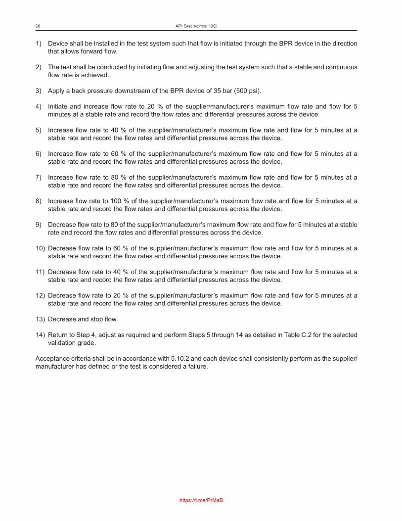
1) Device shall be installed in the test system such that flow is initiated through the BPR device in the direction that allows forward flow.
2) The test shall be conducted by initiating flow and adjusting the test system such that a stable and continuous flow rate is achieved.
3) Apply a back pressure downstream of the BPR device of 35 bar (500 psi).
4) Initiate and increase flow rate to 20 % of the supplier/manufacturer’s maximum flow rate and flow for 5 minutes at a stable rate and record the flow rates and differential pressures across the device.
5) Increase flow rate to 40 % of the supplier/manufacturer’s maximum flow rate and flow for 5 minutes at a stable rate and record the flow rates and differential pressures across the device.
6) Increase flow rate to 60 % of the supplier/manufacturer’s maximum flow rate and flow for 5 minutes at a stable rate and record the flow rates and differential pressures across the device.
7) Increase flow rate to 80 % of the supplier/manufacturer’s maximum flow rate and flow for 5 minutes at a stable rate and record the flow rates and differential pressures across the device.
8) Increase flow rate to 100 % of the supplier/manufacturer’s maximum flow rate and flow for 5 minutes at a stable rate and record the flow rates and differential pressures across the device.
9) Decrease flow rate to 80 of the supplier/manufacturer’s maximum flow rate and flow for 5 minutes at a stable rate and record the flow rates and differential pressures across the device.
10) Decrease flow rate to 60 % of the supplier/manufacturer’s maximum flow rate and flow for 5 minutes at a stable rate and record the flow rates and differential pressures across the device.
11) Decrease flow rate to 40 % of the supplier/manufacturer’s maximum flow rate and flow for 5 minutes at a stable rate and record the flow rates and differential pressures across the device.
12) Decrease flow rate to 20 % of the supplier/manufacturer’s maximum flow rate and flow for 5 minutes at a stable rate and record the flow rates and differential pressures across the device.
13) Decrease and stop flow.
14) Return to Step 4, adjust as required and perform Steps 5 through 14 as detailed in Table C.2 for the selected validation grade.
Acceptance criteria shall be in accordance with 5.10.2 and each device shall consistently perform as the supplier/manufacturer has defined or the test is considered a failure.
API SPecIfIcAtIon 19cI66
https://t.me/PrMaB

TableC.2—CompletionActionsforV3,V2,andV1Validation
V3 V2 V1Adjust back pressure downstream of the BPR device to 104 bar (1,500 psi)
Adjust back pressure downstream of the BPR device to 104 bar (1,500 psi)
Adjust back pressure downstream of the BPR device to 69 bar (1,000 psi)
Perform Steps 5 through 14 once more for a total of two flow cycles
Perform Steps 5 through 14 once more for a total of two flow cycles
Perform Steps 5 through 14 once more for a total of two flow cycles
Stop flow, release test pressures and conclude test
Adjust back pressure downstream of the BPR device to 35 bar (500 psi)
Adjust back pressure downstream of the BPR device to 104 bar (1,500 psi)
Perform Steps 5 through 14 once more for a total of three flow cycles
Perform Steps 5 through 14 once more for a total of three flow cycles
Stop flow, release test pressures and conclude test
Adjust back pressure downstream of the BPR device to 69 bar (1,000 psi)Perform Steps 5 through 14 once more for a total of four flow cyclesAdjust back pressure downstream of the BPR device to 35 bar (500 psi)Perform Steps 5 through 14 once more for a total of five flow cycles
C.6.3 FlowCharacterizationTestatMaximumRatedTemperature
The purpose of this test is to further characterize the performance of the BPR through a range of flow rates which are varied both up and down at the maximum rated temperature. The testing results shall be used in the comparison of the initial data to the final data as described in C.6.9.
Testing shall be performed at, or above, maximum rated temperature. It is recognized that temperature may change the operating pressure of the device. However, change in operating pressure due to the application of temperature should show a predictable trend as identified by a qualified person.
The test system shall allow for applying and changing the fluid back pressure (downstream of the BPR) as flow rate through the device is changed. Flow periods in addition to those defined can be performed at the discretion of the supplier/manufacturer to help establish the desired flow characterization.
The testing procedure is as follows:
1) Device shall be installed in the test system such that flow is initiated through the BPR device in the direction that allows forward flow.
2) The test shall be conducted by initiating flow and adjusting the test system such that a stable and continuous flow rate is achieved.
3) Apply a back pressure downstream of the BPR device to avoid the steaming of fluids when temperature is applied.
4) Increase test temperature to, or above, the supplier/manufacturer’s maximum rated temperature.
5) Perform Steps 5 through 14 of C.6.2, two times.
Acceptance criteria shall be in accordance with 5.10.2 and each device shall consistently perform as the supplier/manufacturer has defined or the test is considered a failure.
Downhole chemIcAl InjectIon DevIceS AnD RelAteD equIPment 67
https://t.me/PrMaB

C.6.4 FlowCharacterizationTestwithTubingReelatMinimumRatedTemperature
The purpose of this test is to further characterize the flow performance of the BPR through a range of flow rates which are varied both up and down with a tubing reel attached. The testing results shall be used in the comparison of the initial data to the final data as described in C.6.9.
Test shall be performed at, or below, the minimum rated temperature and with a tubing reel as defined in 5.10.4.
The test system shall allow for applying and changing the fluid back pressure (downstream of BPR) as flow rate through the device is changed. Flow periods in addition to those defined can be performed at the discretion of the supplier/manufacturer to help establish the desired flow characterization.
The testing procedure is as follows:
1) Device shall be installed in the test system such that flow is initiated through the BPR device in the direction that allows forward flow.
2) The test shall be conducted by initiating flow and adjusting the test system such that a stable and continuous flow rate is achieved.
3) Apply a back pressure downstream of the BPR device of 35 bar (500 psi).
4) Perform Steps 5 through 14 in accordance with C.6.2 two times at the supplier/manufacturer’s minimum rated temperature.
Acceptance criteria shall be in accordance with 5.10.2 and each device shall consistently perform as the supplier/manufacturer has defined or the test is considered a failure.
C.6.5 FlowCharacterizationTestwithCompletionLoading(whereapplicable)
This test is applicable to device designs that are subject to completion loading as defined in 5.3.5. If the supplier/manufacturer can document by verified calculations, analysis or testing results that the BPR is independent from completion loading, this testing is not required.
The purpose of this test is to validate that the flow performance of the BPR device will not be affected in the case of a device design that is subject to completion loadings as defined by the requirements of 5.3.5.
The supplier/manufacturer shall have a documented testing program that evaluates the combined loading of the device at its rated limits (including temperatures) to validate its operation with the defined loads and pressures applied. The testing program shall include multiple temperatures, pressures and loads over a range that demonstrate the breadth of the device's operational capabilities. Applicable acceptance criteria shall be in accordance with 5.10.2.
C.6.6 DifferentialLeakageTestforGradeV1andV2Devices
The purpose of this test is to determine the ability of the BPR to retain fluid inlet pressure when in a no-flow static state when forward injection flow is stopped or is at a pressure less than the crack-open pressure of the device. Some BPR devices may not be intended to provide total closure in the no-flow state and may show some leakage. This test measures the rates of leakage, if any.
Test shall be initially performed at, or below, the minimum rated temperature.
The test commences without a tubing reel; however, later test steps require the inclusion of a tubing reel which shall be as defined in 5.10.4.
API SPecIfIcAtIon 19cI68
https://t.me/PrMaB

Test system shall provide an apparatus for the collection and measurement of potential fluid leakage from the inlet to the outlet of the device in the static no-flow condition.
The testing procedure is as follows:
1) Apply and increase inlet pressure to 10 % to 20 % of the crack-open pressure of the BPR device for a minimum 5-minute hold period.
2) Direct the outlet line of the BPR to the fluid leakage collection apparatus and record the fluid leakage volume and rate collected over the hold period.
3) Increase inlet pressure slowly and forward flow for a minimum of 30 seconds to test BPR function then bleed inlet pressure.
4) Perform Steps 1 through 3 four additional times for a total of five tests at 10 to 20 % of the crack-open pressure of the BPR.
5) Apply and increase inlet pressure to 70 % to 80 % of the crack-open pressure of the BPR device for a minimum 5-minute hold period.
6) Direct the outlet line of the BPR device to the fluid leakage collection apparatus and record the fluid leakage volume and rate collected over the hold period.
7) Increase inlet pressure slowly and forward flow for a minimum of 30 seconds to test BPR function then bleed inlet pressure.
8) Perform Steps 5 through 7 four additional times for a total of five tests at 70 % to 80 % of the crack-open pressure of the BPR device.
9) Connect tubing reel to the inlet line of the BPR device.
10) Perform Steps 1 through 8 one additional time for a total of 20 leakage tests, 10 without the tubing reel and 10 with the tubing reel included.
11) Initiate and increase flow rate to 100 % of the supplier/manufacturer’s rated flow rate and flow for 5 minutes at a stable rate and record the flow rates and differential pressures across the device.
12) Stop injection flow by isolating the tubing reel inlet line.
13) Monitor the inlet pressure for 15 minutes. This to identify reduction in inlet line pressure due to leakage over the BPR element of the device.
14) Increase inlet pressure slowly and forward flow for a minimum of 30 seconds to test BPR function, then bleed inlet pressure
15) Perform Steps 11 through 14 two times for a total of two times, monitoring the inlet pressure with a tubing reel attached.
Acceptance criteria shall be in accordance with 5.10.2 and each device shall consistently perform as the supplier/manufacturer has defined or the test is considered a failure.
C.6.7 DifferentialLeakageTestforGradeV3Devices
The purpose of this test is to determine the ability of the BPR to retain fluid inlet pressure when in a no-flow static state when forward injection flow is stopped or is at a pressure less than the crack-open pressure of the
Downhole chemIcAl InjectIon DevIceS AnD RelAteD equIPment 69
https://t.me/PrMaB
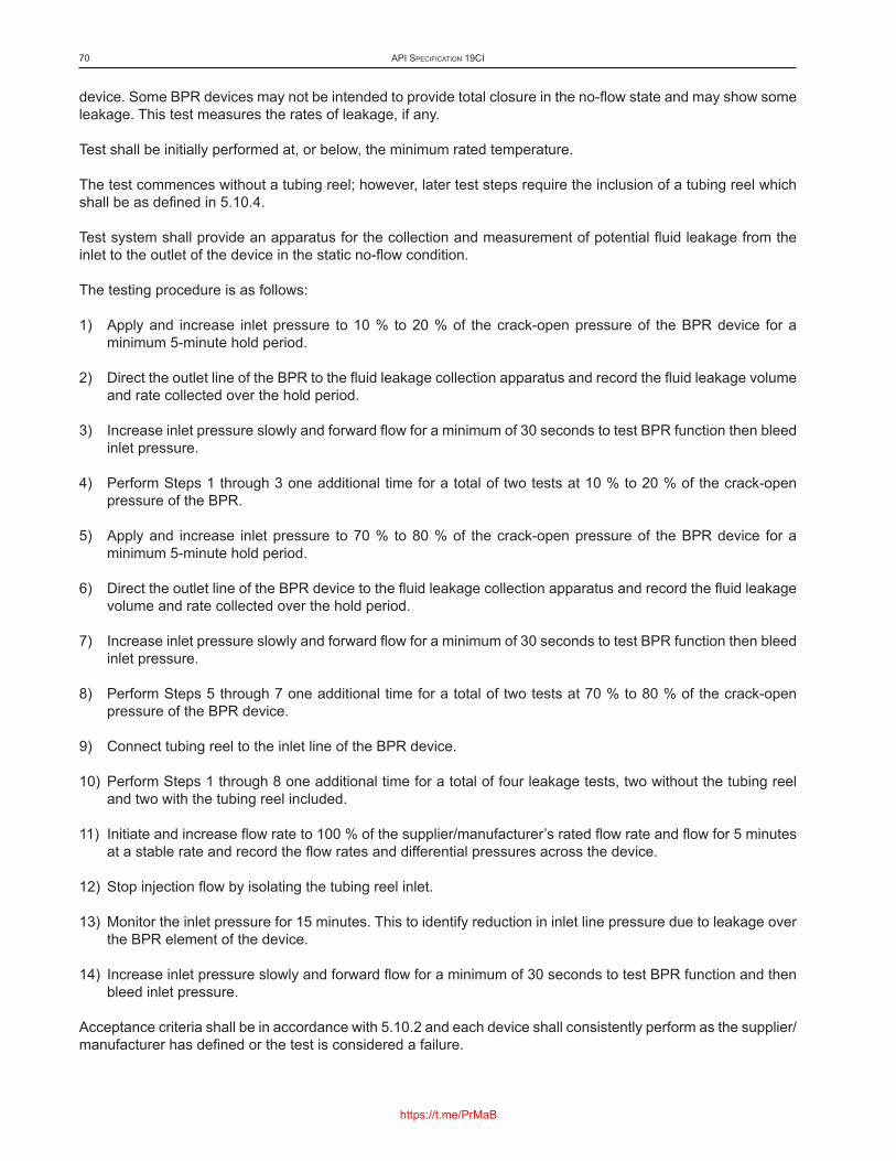
device. Some BPR devices may not be intended to provide total closure in the no-flow state and may show some leakage. This test measures the rates of leakage, if any.
Test shall be initially performed at, or below, the minimum rated temperature.
The test commences without a tubing reel; however, later test steps require the inclusion of a tubing reel which shall be as defined in 5.10.4.
Test system shall provide an apparatus for the collection and measurement of potential fluid leakage from the inlet to the outlet of the device in the static no-flow condition.
The testing procedure is as follows:
1) Apply and increase inlet pressure to 10 % to 20 % of the crack-open pressure of the BPR device for a minimum 5-minute hold period.
2) Direct the outlet line of the BPR to the fluid leakage collection apparatus and record the fluid leakage volume and rate collected over the hold period.
3) Increase inlet pressure slowly and forward flow for a minimum of 30 seconds to test BPR function then bleed inlet pressure.
4) Perform Steps 1 through 3 one additional time for a total of two tests at 10 % to 20 % of the crack-open pressure of the BPR.
5) Apply and increase inlet pressure to 70 % to 80 % of the crack-open pressure of the BPR device for a minimum 5-minute hold period.
6) Direct the outlet line of the BPR device to the fluid leakage collection apparatus and record the fluid leakage volume and rate collected over the hold period.
7) Increase inlet pressure slowly and forward flow for a minimum of 30 seconds to test BPR function then bleed inlet pressure.
8) Perform Steps 5 through 7 one additional time for a total of two tests at 70 % to 80 % of the crack-open pressure of the BPR device.
9) Connect tubing reel to the inlet line of the BPR device.
10) Perform Steps 1 through 8 one additional time for a total of four leakage tests, two without the tubing reel and two with the tubing reel included.
11) Initiate and increase flow rate to 100 % of the supplier/manufacturer’s rated flow rate and flow for 5 minutes at a stable rate and record the flow rates and differential pressures across the device.
12) Stop injection flow by isolating the tubing reel inlet.
13) Monitor the inlet pressure for 15 minutes. This to identify reduction in inlet line pressure due to leakage over the BPR element of the device.
14) Increase inlet pressure slowly and forward flow for a minimum of 30 seconds to test BPR function and then bleed inlet pressure.
Acceptance criteria shall be in accordance with 5.10.2 and each device shall consistently perform as the supplier/manufacturer has defined or the test is considered a failure.
API SPecIfIcAtIon 19cI70
https://t.me/PrMaB

C.6.8 Flow Endurance Test
C.6.8.1 General
The purpose of this test is to determine the ability of the BPR device to function properly after being subjected to a flow endurance test over an extended period. The test shall be conducted by initiating flow and adjusting the test system such that a stable and continuous flow rate is achieved during the total duration of the flowing period. Test shall be performed at, or above, maximum rated temperature and without a tubing reel attached.
The device under test shall remain untouched in the test apparatus. The time required for the application or removal of temperature or time required to reach the maximum flow rate due to breaks in the total flow period is not regarded as part of the accumulated flowing period.
C.6.8.2 Flow Endurance Test Durations
C.6.8.2.1 Validation Grades V1 and V2
For validation grades V1 and V2 perform the testing as defined. The accumulated 240-hour flowing period may be achieved by either flowing without interruption for the full 240 hours or the accumulated period may be made up of separate shorter flowing periods.
C.6.8.2.2 Validation Grade V3
For V3 devices, the flow period shall be an accumulated 80 hours.
C.6.8.3 Flow Endurance Test Procedure
At the end of continuous flow period, it is required to validate the device function. This is to identify if damage has occurred to the BPR during the preceding flow period and to allow the supplier/manufacturer to terminate the test at this point.
Perform the following test steps:
1) Maintain the position of the device in the test fixture.
2) Apply maximum rated temperature, or above, to the text fixture and allow temperature to stabilize.
3) Isolate devices which are used for collection of leakage from the device inlet to outlet.
4) Apply a back pressure downstream of the BPR device to avoid the steaming of fluids when temperature is applied.
5) Initiate and increase flow rate to 20 % of the supplier/manufacturer’s maximum flow rate and flow for 5 minutes at a stable rate and record the flow rates and differential pressures across the device.
6) Increase flow rate to 40 % of the supplier/manufacturer’s maximum flow rate and flow for 5 minutes at a stable rate and record the flow rates and differential pressures across the device.
7) Increase flow rate to 60 % of the supplier/manufacturer’s maximum flow rate and flow for 5 minutes at a stable rate and record the flow rates and differential pressures across the device.
Downhole chemIcAl InjectIon DevIceS AnD RelAteD equIPment 71
https://t.me/PrMaB

8) Increase flow rate to 80 % of the supplier/manufacturer’s maximum flow rate and flow for 5 minutes at a stable rate and record the flow rates and differential pressures across the device.
9) Increase flow rate to 100 % of the supplier/manufacturer’s maximum flow rate and flow for 5 minutes at a stable rate and record the flow rates and differential pressures across the device.
10) Increase flow rate to 120 % of the supplier/manufacturer’s maximum flow rate and flow for 5 minutes at a stable rate and record the flow rates and differential pressures across the device.
11) Increase flow rate to 140 % of the supplier/manufacturer’s maximum flow rate and flow for 5 minutes at a stable rate and record the flow rates and differential pressures across the device.
12) Increase flow rate to 150 % of the supplier/manufacturer’s maximum flow rate and flow for 5 minutes at a stable rate and record the flow rates and differential pressures across the device.
13) Compare the measured differential pressures across the device with the differential pressures from the initial testing as obtained in C.6.3.
14) Flow at a stable and continuous flow rate of 150 % of the supplier/manufacturer’s maximum flow rate and the maximum rated temperature for the accumulated total flow duration.
15) Stop flowing and and isolate the inlet line.
16) Monitor the inlet pressure for 15 minutes to identify reduction in inlet line pressure due to leakage over the BPR element of the device.
17) If the full flow period has been achieved, the test is considered acceptable and the test may be concluded. If the accumulated flow period is less than the full flow period, continue to flow until the required full flow period is achieved.
18) Retain the test arrangement in preparation for the final testing phase.
Acceptance criteria shall be in accordance with 5.10.2 and the following:
a) a predictable trend shall be shown by variations in data;
b) each device shall consistently perform as the supplier/manufacturer has defined or the test is considered a failure.
At Step 16, a qualified person shall compare the operational curve with previous data to ensure normal operation. In the event where leakage rates are defined as abnormal values the test has failed.
C.6.9 Comparison of Initial Data to Final Data for Validation Test Report
This final test phase is required to compare device performance before and after the flow endurance test (Step 6 of Table C.1).
At the successful conclusion of the validation testing steps defined in Table C.1 for a specific BPR design, the resultant data shall be compiled, and the results reviewed by a qualified person. A portion of this review shall include a comparison of the initial validation testing results with the final validation testing results.
Also, the results of the pre- and post-testing inspections shall be reviewed and considered. The differences in these results shall be within the supplier/manufacturer's documented standard operational ranges. The qualified person shall document the review of the results and observations. A second qualified person shall review and approve the report.
API SPecIfIcAtIon 19cI72
https://t.me/PrMaB

C.7 Functional Testing
C.7.1 General
The user/purchaser shall specify the grade of device functional tests to be conducted on the chemical injection device(s). Each functional test grade requires a number of individual functional test procedure(s), process(s) or test(s) to demonstrate conformance with the requirements. The procedures and testing results shall be maintained and shall be traceable to the individual device(s).
The testing fluid should be distilled or de-ionized water, and the use of a reel of tubing is not necessary for these tests.
C.7.2 Functional Testing Grades
The three grades of device functional testing are designated as F3, F2, and F1. The grade is selected by the user/purchaser when the device is ordered.
C.7.3 Functional Testing Requirements
The following Table C.3 specifies the functional test requirements and references the specific testing section. Each test shall be successfully completed prior to shipping the device.
NOTE General testing requirements are included in 5.10.
TableC.3—BackPressureRetention(BPR)FunctionalTestingSummary
Step Functional Test DescriptionFunctional Grade
F3 F2 F11 Flow Characterization Test S/M C.7.5.2 C.7.5.32 Differential Leakage Functional Test S/M C.7.5.4 C.7.5.4
NOTE S/M indicates supplier/manufacturer documented testing results that verify the defined performance.
C.7.4 Functional Requirements for Grade F3 Devices
Functional testing requirements for F3 devices shall include tests to verify the device’s ratings. The supplier/manufacturer shall demonstrate and document that the test results meet the documented requirements of the device ratings.
C.7.5 Functional Requirements for Grade F1 and F2 Devices
C.7.5.1 General
Each device manufactured shall successfully pass the user/purchaser specified functional testing grade. The following tests are required as identified in Table C.3. Test shall be performed at or below the minimum rated temperature.
Downhole chemIcAl InjectIon DevIceS AnD RelAteD equIPment 73
https://t.me/PrMaB

C.7.5.2 Flow Function Test at Minimum Rated Temperature—Grade F2
The purpose of this test is to confirm the flow profile of the BPR device when subjected to flow up to the maximum flow rate. Additional flow periods can be performed at the discretion of the supplier/manufacturer to help confirm the flow performance.
The testing procedure is as follows:
1) Prepare and pressure test the test arrangement according to documented procedures to verify test arrangement function and integrity.
2) Position the device in the test fixture and perform a fluid leakage test to verify pressure integrity.
3) Device shall be installed in the test system such that flow is initiated through the BPR device in the direction that allows forward flow.
4) The test shall be conducted by initiating flow and adjusting the test system such that a stable and continuous flow rate is achieved.
5) Apply a back pressure downstream of the BPR device of 35 bar (500 psi).
6) Initiate and increase the flow rate to 100 % of the supplier/manufacturer’s maximum flow rate and flow for 5 minutes at a stable rate; log and record the flow rates and differential pressures across the device.
7) Increase the back pressure to 69 bar (1000 psi) and flow for 5 minutes at a stable rate; log and record the flow rates and differential pressures across the device.
8) Decrease the back pressure to 35 bar (500 psi) and flow for 5 minutes at a stable rate; log and record the flow rates versus the differential pressures across the device.
9) Adjust the flow rate to 50 % of the supplier/manufacturer’s maximum flow rate.
10) Perform Step 8 and Step 9 one additional time at 50 % of the supplier/manufacturer’s maximum flow rate.
11) Adjust the flow rate to the supplier/manufacturer’s minimum flow rate.
12) Perform Step 8 and Step 9 one additional time at the supplier/manufacturer’s minimum flow rate.
Acceptance criteria shall be in accordance with 5.10.2 and the following:
a) the device shall consistently perform as the supplier/manufacturer has defined;
b) the flow rates and differential pressures across the device shall be within the supplier/manufacturer defined limits.
C.7.5.3 Flow Function Test at Minimum Rated Temperature—Grade F1
The purpose of this test is to confirm the flow profile of the BPR device when subjected to flow up to the maximum flow rate. Additional flow periods can be performed at the discretion of the supplier/manufacturer to help confirm the flow performance.
The testing procedure is as follows:
1) Prepare and pressure test the test arrangement according to documented procedures to verify test arrangement function and integrity.
API SPecIfIcAtIon 19cI74
https://t.me/PrMaB

2) Position the device in the test fixture and perform a fluid leakage test to verify pressure integrity.
3) The device shall be installed in the test system such that flow is initiated through the BPR device in the direction that allows forward flow.
4) The test shall be conducted by initiating flow and adjusting the test system such that a stable and continuous flow rate is achieved.
5) Apply a back pressure downstream of the BPR device of 35 bar (500 psi).
6) Initiate and increase the flow rate to 100 % of the supplier/manufacturer’s maximum flow rate and flow for 5 minutes at a stable rate; log and record the flow rates and differential pressures across the device.
7) Increase the back pressure to 69 bar (1000 psi) and flow for 5 minutes at a stable rate; log and record the flow rates and differential pressures across the device.
8) Increase the back pressure to 104 bar (1500 psi) and flow for 5 minutes at a stable rate; log and record the flow rates and differential pressures across the device.
9) Decrease the back pressure to 69 bar (1000 psi) and flow for 5 minutes at a stable rate; log and record the flow rates and differential pressures across the device.
10) Decrease the back pressure to 35 bar (500 psi) and flow for 5 minutes at a stable rate; log and record the flow rates and differential pressures across the device.
11) Adjust the flow rate to 50 % of the supplier/manufacturer’s maximum flow rate.
12) Perform Steps 9 through 11 one additional time at 50 % of the supplier/manufacturer’s maximum flow rate.
13) Adjust the flow rate to minimum of the supplier/manufacturer’s flow rate.
14) Perform Steps 9 through 11 one additional time at a minimum of the supplier/manufacturer’s flow rate.
Acceptance criteria shall be in accordance with 5.10.2 and the following:
a) the device shall consistently perform as the supplier/manufacturer has defined;
b) the flow rates and differential pressures across the device shall be within the supplier/manufacturer’s defined limits.
C.7.5.4 DifferentialLeakageFunctionalTestatMinimumRatedTemperature
The purpose of this test is to verify the performance of the BPR device to retain fluid inlet pressure when in a no flow static state at inlet pressures lower than the BPR forward flowing pressure.
The supplier/manufacturer may include a tubing reel or accumulator of appropriate and documented volume on the inlet side of the BPR in this test system.
The test system shall also provide apparatus to allow for collection and measurement of fluid that may leak from the inlet to the outlet of the device in the static no-flow condition.
1) Apply and increase inlet pressure to 10 % to 20 % of the crack-open pressure of the BPR device for a minimum 5-minute hold period.
2) Direct the outlet line of the BPR device to the fluid leakage collection apparatus and record the fluid leakage volume and rate collected over the hold period.
Downhole chemIcAl InjectIon DevIceS AnD RelAteD equIPment 75
https://t.me/PrMaB

3) Increase inlet pressure slowly and forward flow for a minimum of 30 seconds to verify BPR function then bleed inlet pressure.
4) Apply and increase inlet pressure to 70 % to 80 % of the crack-open pressure of the BPR device for a minimum 5-minute hold period.
5) Direct the outlet line of the BPR device to the fluid leakage collection apparatus and record the fluid leakage volume and rate collected over the hold period.
6) Increase inlet pressure slowly and forward flow for a minimum of 30 seconds to verify BPR function then bleed inlet pressure.
7) Initiate and increase flow rate to 100 % of the supplier/manufacturer’s rated flow rate and flow for 5 minutes at a stable rate and record the flow rates and differential pressures across the device.
8) Stop injection flow by isolating the tubing reel or accumulator inlet line.
9) Monitor the inlet pressure for 15 minutes. To identify reduction in inlet line pressure due to leakage within the BPR device.
10) Increase inlet pressure slowly and forward flow for a minimum of 30 seconds to verify BPR function then bleed inlet pressure.
Acceptance criteria shall be in accordance with 5.10.2 and each device shall consistently perform as the supplier/manufacturer has defined or the test is considered a failure.
C.7.5.5 Functional Test Report
The functional test report shall be prepared for each test according to the requirements of 5.10. The final test report shall be prepared and approved per the supplier/manufacturer’s requirements.
API SPecIfIcAtIon 19cI76
https://t.me/PrMaB

AnnexD (normative)
Single-use Isolation Validation and Functional Testing Requirements
D.1 General
This annex defines the SUI design validation and functional testing requirements for chemical injection devices that perform the SUI function as defined in Table 1. For validation to the selected grade level, each design, type and size shall successfully complete the testing identified in Table D.1.
Retrievable SUI devices shall be validated to the requirements of this annex, and the requirements of Annex F. For retrievable SUI systems, this test shall also verify that the external seal assemblies are activated effectively.
For liquid validation tests of Grade V1 and V2 devices, the test fluid shall be water. Test fluids utilized in V4 testing shall be documented in the test report.
NOTE General testing requirements are included in 5.11 and design changes are included in 5.8.
D.2 DevicesforOpeningPressureDesignVerification
D.2.1 General
The device that is tested shall be manufactured within a manufacturing system and processes which provide devices of repeatable performance.
A device shall not be repaired or serviced during a test, other than to replace a shearable/frangible component(s).
The supplier/manufacturer shall document the normal direction of pressure isolation, and the maximum isolation pressure rating of the SUI. This pressure shall be used as the maximum isolation pressure. The activation pressure is validated in the applicable tests of this annex. The supplier/manufacturer shall document the operation of the SUI in the presence of a defined downstream pressure.
D.2.2 Single-use Isolation Device Pressures
The SUI device has a maximum housing pressure rating, which is the maximum pressure when the SUI device is open. This rating is established by performing the steps according to 5.9.5.3.
The isolating mechanism of the SUI device has a maximum isolation pressure rating for isolating pressure at its inlet from pressure at its outlet. This maximum isolation pressure rating differs from the maximum housing pressure rating; the maximum isolation pressure rating is only the isolating differential pressure capability from inlet to outlet. The maximum isolation pressure rating shall not be greater than the maximum housing pressure rating.
The isolating mechanism also has an activation pressure that opens the SUI device. The activation pressure differs from the maximum isolation pressure rating; the activation pressure is the opening pressure only. The activation pressure, including its tolerance, shall not be greater than the maximum isolation pressure rating.
77
https://t.me/PrMaB

D.3 Single-useIsolationDeviceActivationPressureChanges
The (original) validation testing in Table D.1 shall be conducted on a supplier/manufacturer’s SUI device with the maximum isolation pressure rating and greatest activation pressure. The SUI device with a lesser activation pressure is considered validated.
D.4 Design Validation Grades
The available design validation grades are V4, V2, and V1; V3 is not applicable for this type of device. Users/purchasers shall specify the grade in the functional specification.
D.5 Design Validation Testing Requirements
The V1 and V2 validation testing in Table D.1 shall be performed in the order shown in its entirety. If a device fails a test, see the requirements included in 5.10.
The V4 design validation testing shall include each of the requirements identified in Table D.1. The V4 test report shall indicate the order of the testing and detailed testing results.
The V2 validation testing shall be successfully performed on one device of a design.
The V1 validation testing shall be successfully performed on two devices of a design.
TableD.1—Single-useIsolation(SUI)ValidationTestingSummary
Step Validation Test DescriptionValidation Grade
V4 V2 V11 Isolation Pressure Test D.5 D.7.2 D.7.22 Opening Validation Test at Minimum Rated Temperature D.5 D.7.3 D.7.33 Surge Validation Test at Minimum Rated Temperature D.5 D.7.4 D.7.44 Opening Validation Test at Maximum Rated Temperature D.5 D.7.5 D.7.55 Compilation of Validation Test Report D.5 D.7.6 D.7.6
D.6 Validation Requirements for Grade V4 Devices
Validation requirements for V4 devices shall conform to 5.9.3 and 5.9.4.
D.7 Validation Requirements for Grade V1 and V2 Devices
D.7.1 General
The tests described in D.7.2 through D.7.5 shall be performed on V1 and V2 devices.
D.7.2 Isolation Pressure Test at Minimum and Maximum Rated Temperature
This test validates the SUI device will isolate pressure in the normal direction of isolation to the maximum rated isolation pressure of the SUI device. The testing shall be performed initially at, or below, the minimum rated
API SPecIfIcAtIon 19cI78
https://t.me/PrMaB

temperature and will be heated to, or above the maximum rated temperature within the test. The testing shall be performed without a tubing reel.
This test validates the ability of the SUI device/product to isolate pressure from its inlet to its outlet. The purpose of the test is not to validate the shear out element itself, such as a frangible burst disc.
The rating of any shear-out element used in the SUI device shall not exceed the maximum rated SUI isolation pressure and temperature of the SUI device.
For the purposes of performing the test, the supplier/manufacturer may use a documented method to ensure the SUI will not activate to allow the defined isolation test pressure to be applied. Methods employed for this purpose shall be documented in the test report.
If the SUI technology allows a pressure to be isolated in both the normal forward direction and the reverse direction, the following test shall be conducted in both directions and the test results documented.
The following test steps are required:
1) Install device in test system.
2) Adjust the temperature to, or below the minimum rated temperature and apply the maximum rated isolation pressure to the inlet of device for a 15-minute hold period.
3) Release test pressures.
4) Adjust the temperature to, or above the maximum temperature, and apply the maximum rated isolation pressure to inlet of device for a 15-minute hold period.
5) Release test pressures.
6) Remove temperature and allow device to cool to, or below, the minimum rated temperature.
7) When at the minimum temperature, or below, apply maximum rated isolation pressure to the inlet of the device for a 15-minute hold period.
8) Release test pressures.
Acceptance criteria shall be in accordance with 5.10.2 and isolation pressure testing shall not allow deformation, distortion or physical change outside of the allowable tolerances as defined by the supplier/manufacturer.
D.7.3 Opening Validation Test at Minimum Rated Temperature
This test acts on the shear-out, or other opening mechanism, of the SUI device/product and validates the SUI will open at a pressure lower than the maximum rated isolation value obtained in D.7.2. The maximum SUI opening pressure shall not exceed the maximum isolation pressure as defined in D.7.2. The device shall open to allow forward flow as designed by the supplier/manufacturer. This test shall demonstrate a consistent opening operation over three tests within a defined tolerance. Testing shall be performed without a tubing reel at or below the minimum rated temperature.
The following test steps are required.
1) Apply hydraulic pressure to the inlet of the device and increase pressure upwards to the device’s intended opening pressure at a rate that will allow accurate collection of pressure data at the point of opening.
2) Record and log the opening pressure range of the device.
Downhole chemIcAl InjectIon DevIceS AnD RelAteD equIPment 79
https://t.me/PrMaB

3) Increase inlet pressure and forward flow to 100 % of the supplier/manufacturer’s specified maximum flow rate for a minimum of 5 minutes. Log and record the flow rates and differential pressures across the device.
4) Replace/reset the shear-out (frangible) element and re-install in the test system, where applicable.
5) Perform Steps 1 through 4 two additional times for a total of three tests.
For V1 devices, perform the test of D.7.3 on a second device.
Acceptance criteria shall accord with 5.10.2 and the following.
a) Each device shall consistently open within the defined tolerances of the supplier/manufacturer.
b) If the recorded opening differential pressure is outside the supplier/manufacturer’s allowable tolerances, as defined by a qualified person, the test has failed.
c) Recorded pressure and flow data from Step 3 shall be compared with each of the three tests to the supplier/manufacturer’s expected pressure loss values. The flowing pressure differentials shall conform to the supplier/manufacturer's defined values.
D.7.4 Surge Validation Test at Minimum Rated Temperature
This test validates that the SUI will open as designed by the supplier/manufacturer and once opened, is not affected by a surge of fluid that may occur from an injection line volume. This test shall demonstrate that a volume of fluid released rapidly through the device will not cause it to function outside the supplier/manufacturer's operational requirements.
This test validates the SUI will open at a pressure lower than the maximum rated isolation value obtained in D.7.2. The maximum SUI opening pressure shall not exceed the maximum isolation pressure as defined in D.7.2.
Test shall be performed at or below the minimum rated temperature with a tubing reel as defined in 5.10.4.
The following test steps are required.
1) Apply hydraulic pressure to the inlet of the device and increase pressure upwards to the device’s opening pressure at a rate that allows accurate measurement of pressure at the point of opening.
2) Record the opening pressure of the device.
3) Allow fluid pressure in the tubing reel to dissipate and pressures to stabilize.
4) Increase inlet pressure and forward flow at 100 % of the supplier/manufacturer’s specified maximum flow rate. Flow at a stable flow rate for a minimum of 5 minutes. Log and record the flow rates and differential pressures across the device.
5) Replace/reset the shear-out (frangible) element and re install in the test system, as applicable.
6) Perform Steps 1 through 5 two additional times for a total of three tests.
For V1 devices, perform the test of D.7.4 on a second device.
Acceptance criteria shall be in accordance with 5.10.2 and the following.
a) Each device shall consistently open within the tolerances of the supplier/manufacturer. If the recorded opening differential pressures are outside of the supplier/manufacturer’s tolerances, as defined by a qualified person, the test has failed.
API SPecIfIcAtIon 19cI80
https://t.me/PrMaB

b) Each device shall show consistent flow and pressure decline as pressure and volume in the tubing reel stabilizes. If a surge of fluid causes the device to function outside of the supplier/manufacturer’s requirements, then the test has failed.
c) Recorded pressure and flow data for Step 4 shall be compared for each of the three tests to the supplier/manufacturer’s expected pressure loss values. The flowing pressure differentials shall conform to the supplier/manufacturer's defined values.
D.7.5 Opening Validation Test at Maximum Rated Temperature
Perform the test in D.6.3 at or above the maximum rated temperature.
D.7.6 Compilation of Validation Test Report
At the successful conclusion of the validation testing steps defined in Table D.1 for a specific design, the resultant data shall be compiled and reviewed by a qualified person. A second qualified person shall review and approve the report.
D.8 Functional Testing
D.8.1 General
Each device manufactured to this specification shall be functionally tested to the following requirements:
The user/purchaser shall specify the grade of device functional tests to be conducted on the chemical injection device(s). Each functional test grade requires a number of individual functional test procedure(s), process(s), or test(s) to demonstrate conformance with the requirements. The procedures and results shall be maintained and shall be traceable to the individual device(s).
The testing fluid shall be water, and the use of a reel of tubing is not necessary for these tests.
D.8.2 Functional Testing Grades
The three grades of device functional testing are F3, F2, and F1. The grade is selected by the user/purchaser when the device is ordered.
D.8.3 Functional Testing Requirements
Table D.2 sets the functional test requirements and references the specific testing section. Each test shall be successfully completed prior to shipping the device.
TableD.2—Single-useIsolation(SUI)FunctionalTestingSummary
Step Functional Test DescriptionFunctional Grade
F3 F2 F11 Opening Pressure Verification D.7.4 D.7.5.2 D.7.5.22 Installation Integrity Test D.7.4 D.7.5.3 D.7.5.3
Downhole chemIcAl InjectIon DevIceS AnD RelAteD equIPment 81
https://t.me/PrMaB

D.8.4 Functional Requirements for Grade F3 Devices
Functional testing requirements for F3 devices shall include tests to verify the device’s ratings as defined in 5.3.2. The supplier/manufacturer shall demonstrate and document that the test results meet the documented requirements of the device ratings.
D.8.5 Functional Requirements for Grade F1 and F2 Devices
D.8.5.1 General
Each device manufactured shall successfully pass the user/purchaser specified functional testing grade. The required tests are defined in Table D.2 and detailed in D.8.5.2 and D.8.5.3.
D.8.5.2 OpeningPressureVerification
The purpose of this process is to verify that the opening pressure of the SUI will be as designed. The supplier/manufacturer shall have a documented procedure that when implemented and passed verifies each production SUI will be open as intended. The supplier/manufacturer shall conduct sample tests of the SUI device’s activation component per AQL requirements in 6.8. Supplier/manufacturers shall test the device/product to minimum of 50 % of the activation pressure. The applicable acceptance criteria are defined in 5.10.2.
D.8.5.3 InstallationIntegrityTest
The purpose of this test is to verify that the assembled SUI demonstrates the capability to isolate pressure. The supplier/manufacturer shall have a documented testing procedure that verifies production SUI isolation integrity. This process shall include applicable acceptance criteria as defined in 5.10.2.
D.8.5.4 Functional Test Report
The functional test report shall be prepared for each test according to the requirements of 5.10. The final test report shall be prepared and approved per the supplier/manufacturer’s requirements.
API SPecIfIcAtIon 19cI82
https://t.me/PrMaB

AnnexE (normative)
SecondaryChemicalInjectionScreenValidationandFunctionalTesting
Requirements
E.1 General
This annex defines the SCIS design validation and functional testing requirements for chemical injection devices that perform the SCIS function as defined in Table 1. For validation to the selected grade, each design, type, and size shall successfully complete the testing identified in Table E.1.
Retrievable SCIS devices shall also be validated to the requirements of this annex and the requirements of Annex F. For retrievable systems, this test shall also verify that the external seal assemblies are activated effectively.
For liquid validation tests of V1 and V2 devices unless stated otherwise the test fluid shall be water. This test fluid is recognized as a baseline fluid for operational evaluations. Test fluids utilized in V4 testing shall be documented on the test report.
NOTE General testing requirements are included in 5.10 and design changes are included in 5.8.
E.2 Devices for Design Validation Testing
The device that is tested shall be manufactured within a manufacturing system and processes which provide devices of repeatable performance.
During each test, each device under test shall not be repaired or serviced. If a device fails a test, see the requirements of 5.10.2.
The supplier/manufacturer shall document the normal direction of flow. The supplier/manufacturer shall also document the operation of the SCIS when flow occurs in the reverse direction.
The supplier/manufacturer shall establish the debris collection capability of the SCIS element with either a documented testing program, verified manufacturer’s data, or other verified calculations. Such debris collection capabilities shall be reviewed and approved by a qualified person and shall be part of supplier/manufacturer documentation.
E.3 Design Validation Grades
The available design validation grades are V4, V2, and V1; V3 is not applicable for this type of device. Users/purchasers shall specify the grade in the functional specification.
E.4 Design Validation Testing Requirements
The design validation requirements that shall be performed for each SCIS chemical injection device design, are defined in Table E.1. Each design is required to pass the entire validation criteria. The V1 and V2 validation testing in Table E.1 shall be performed as identified in the order shown.
The V4 design validation testing shall include each of the requirements identified. The V4 test report shall indicate the order of the testing and detailed testing results.
83
https://t.me/PrMaB

The V2 validation testing shall be successfully performed on one device of each design.
The V1 validation testing shall be successfully performed on two devices of a design.
TableE.1—SecondaryChemicalInjectionScreen(SCIS)ValidationTestingSummary
Step Validation Test DescriptionValidation Grade
V4 V2 V11 Element Flow Characterization E.5 E.6.2 E.6.22 Housing Flow Characterization E.5 E.6.3 E.6.33 Combined Element and Housing Flow Characterization E.5 E.6.4 E.6.44 Element Internal and External Failure Pressures E.5 E.6.5 E.6.55 By-pass Mechanism Validation Test (where applicable) E.5 E.6.6 E.6.66 Compilation of Validation Test Report E.5 E.6.7 E.6.7
E.5 Validation Requirements for Grade V4 Devices
Validation requirements for V4 devices shall be performed in accordance with 5.9.3 and 5.9.4.
E.6 Validation Requirements for Grade V1 and V2 Devices
E.6.1 General
The tests described in E.6.2 through E.6.7 shall be performed on V1 and V2 devices.
E.6.2 ElementFlowCharacterization
The supplier/manufacturer shall have a documented process to produce a flow characterization for the SCIS element design. This evaluation excludes the element's installation housing, which is validated in E.6.3. If it is not feasible to characterize separately the flow performance of the element and housing, supplier/manufacturers may combine into a single flow characterization both the element and housing per E.6.4.
Computational methods as defined in 5.7.2 can be used to establish the flow characterization. This shall be validated by testing results. The physical testing results and/or computational methods used to develop the flow characterization can be the basis for estimation by a qualified person of the flow performance when other fluids are used.
The flow characterization and the related reference information shall be documented in the design records.
E.6.3 HousingFlowCharacterization
The supplier/manufacturer shall have a documented process to produce a flow characterization for the secondary chemical injection screen (SCIS) housing. This evaluation excludes the element's performance evaluation, which is validated in E.6.2.
The supplier/manufacturer can demonstrate the flow characterization of the housing by computational methods as defined in 5.7.2; otherwise, a flow test shall be performed. Testing results shall be compared to the results of E.6.2 and may be used to establish pressure or flow rate losses that may occur within the housing. The physical
API SPecIfIcAtIon 19cI84
https://t.me/PrMaB

testing results and/or computational methods used to develop the flow characterization can be the basis for estimation by a qualified person of the flow performance when other fluids are used.
The flow characterization and the related reference information shall be documented in the design records.
E.6.4 CombinedElementandHousingFlowCharacterization
The supplier/manufacturer shall have a documented process to produce a flow characterization for the assembled SCIS element and housing. This shall include the requirements defined in the element’s characterization (E.6.2) and the housing’s characterization (see E.6.3).
This can be achieved by performing step E.6.2 and E.6.3 separately or by consolidating them into one single test.
Where an element or housing has been separately validated in accordance with the requirements of E.6.2 or E.6.3, respectively, the data may be consolidated by a qualified person to validate the device’s flow performance to the design’s ratings.
E.6.5 Element Internal and External Failure Pressure
The supplier/manufacturer shall have documented procedures that establish the internal and external failure pressures of the SCIS element at the maximum rated temperature.
The supplier/manufacturer can establish the internal and external failure pressures of the SCIS element by testing or computational methods as defined in 5.7.2. Computational limits shall be approved and documented by a qualified person.
The internal and external failure pressures shall be used to establish the SCIS ratings and may be used to establish the ratings of other features such as the pressures required to activate a bypass mechanism. Testing shall validate the ratings of the SCIS element design.
E.6.6 By-passMechanismValidationTest(whereapplicable)
The supplier/manufacturer shall have documented testing procedures that tests the SCIS by-pass function at its rated limits of temperatures and pressures. This test validates the function of the by-pass mechanism within the SCIS. The supplier/manufacturer may use a blank to simulate a blocked SCIS element for the purposes of this test.
The testing shall include a flow validation test of the activated by-pass mechanism and the acceptance criteria shall be defined. The results shall be within the supplier/manufacturer’s documented ratings. A qualified person shall document and review the results and any observations.
E.6.7 Compilation of Validation Test Report
At the successful conclusion of the validation testing steps defined in Table E.1 for a specific design, the resultant data shall be compiled, and the results reviewed by a qualified person. A second qualified person shall approve the results.
E.7 Functional Testing Requirements
Each device manufactured to this specification shall be functionally tested to a single grade of functional requirements—F1. Suppliers/manufacturers shall have a documented testing program. The testing fluid shall be
Downhole chemIcAl InjectIon DevIceS AnD RelAteD equIPment 85
https://t.me/PrMaB

water. The use of a tubing reel is not necessary. The supplier/manufacturer shall document the functional testing results.
E.8 Functional Test Report
The functional test report shall be prepared for each device tested according to the requirements of 5.10. The final test report shall be prepared and approved per the supplier/manufacturer’s requirements of final data.
API SPecIfIcAtIon 19cI86
https://t.me/PrMaB

AnnexF (normative)
Retrievable Chemical Injection Device/Product Testing
F.1 General
This annex defines the validation testing for retrievable chemical injection device/product designs. This annex applies to design validation grades V1, V2, and V4. For conformance to the selected grade level, each design, type and size shall successfully complete the testing defined in Table F.1. Devices shall conform to the requirements described in Tables B.1, C.1, D.1, and E.1, as applicable.
Each tool utilized in the performance of the testing (see API 19G1 and API 19G3 for more information) shall be identified by the name of the supplier/manufacturer, the name of each additional device/tool(s), unique part/product number and serial//identification number.
For liquid validation tests the test fluid shall be water, this is recognized as a baseline fluid for operational evaluations. Test fluids utilized in V4 testing shall be documented by the supplier/manufacturer in the test report(s).
NOTE General testing requirements are included in 5.10 and design changes are included in 5.8.
F.2 Design Validation Testing
The device/product that is tested shall be manufactured within a manufacturing system and processes which provide devices/products of repeatable performance. During each series of validation tests, each device/product under test shall not be repaired or serviced.
The design validation testing as defined in F.6.2 and F.6.4 may be combined into a single series of testing where the procedure is approved by a qualified person as not affecting the testing results as defined above.
F.3 Design Validation Grades
The available design validation grades are V4, V2, and V1; V3 is not applicable for this type of device. Users/purchasers shall specify the grade in the functional specification.
F.4 Design Validation Testing Requirements
Perform the testing defined in Table F.1.
The V4 design validation testing shall include each of the requirements identified. The V4 test report shall indicate the order of the testing and detailed testing results.
The V2 and V1 validation testing shall be successfully performed on one device/product of each design.
The external seal assembly validation testing liquid utilizes water as a test medium; therefore, this validation does not qualify the external seal assembly for use in a defined chemical injection environment.
87
https://t.me/PrMaB

TableF.1—RetrievableValidationTestingSummary
Step Validation Test DescriptionValidation Grade
V4 V2 V11 Interface Test S/M F.6.2 F.6.22 Insertion Effects Test S/M F.6.3 F.6.33 External Seal Assembly Validation with Liquid S/M F.6.4 F.6.44 External Seal Assembly Validation with Gas N/A N/A F.6.55 Compilation of Validation Test Report F.5 F.7 F.7
NOTE S//M indicates supplier/manufacturer documented testing results that validate the defined performance. N/A indicates a non-applicable step for that validation grade.
F.5 Validation Requirements for Grade V4
Validation requirements for V4 devices/products shall conform to 5.9.3 and 5.9.4.
F.6 Validation Requirements for Grades V1 and V2
F.6.1 General
The tests identified in Table F.1 are required for validation of device/product designs to conform to this specification.
F.6.2 Interface Test
Interface testing shall be performed with each combination of side-pocket mandrel, running tool, pulling tool, kick-over tool and latch (see API 19G1 and 19G3) where compatibility is claimed to verify safe and proper installation and retrieval of the retrievable chemical injection device/product.
Test shall be performed with the side-pocket mandrel secured in a horizontal position with the valve pocket located in 3 different indexing positions, which are approximately at 12, 3, and 6 o’clock.
The testing procedure shall be performed as follows.
1) Attach the retrievable chemical injection device to associated latch/running tool/kick-over tool.
2) Activate kick-over tool.
3) Insert the retrievable chemical injection device into the pocket bore of the side-pocket mandrel.
4) Shear the running tool from the retrievable chemical injection device. The latch locking mechanism shall be fully engaged under/in the mandrel locking profile.
5) Connect an associated pulling tool/kick-over tool to the latch or running head, or both, on the retrievable chemical injection device.
6) Retrieve the retrievable chemical injection device from the pocket bore of the side-pocket mandrel.
7) Perform the testing on each combination of equipment and at the defined index positions.
Acceptance criteria shall be as follows:
API SPecIfIcAtIon 19cI88
https://t.me/PrMaB

a) all test steps defined above shall be completed successfully;
b) the retrievable chemical injection device, external seal assembly and latch shall not be damaged in a way that precludes their intended operation;
c) if any damage is observed, it shall be documented and photographed.
F.6.3 Insertion Effects Test
This test verifies that the characteristics and performance of the retrievable chemical injection device/product remains essentially unchanged after installation into a defined side-pocket mandrel. This testing shall be performed at ambient temperature. Pressure testing shall be performed with water.
The supplier/manufacturer shall also prepare a detailed testing procedure for the device/product being tested including the identification of the equipment used. Devices/products shall be installed into and retrieved from the side-pocket mandrel using a defined procedure. Insertion testing shall be performed with the side-pocket mandrel secured.
The supplier/manufacturer shall define and record the functional characteristics of the specific device/product to determine which ratings shall be functionally verified after installation into the side pocket mandrel. The defined characteristics shall be within the validated ranges. Products that contain an SUI and SCIS device shall be tested at the minimum pressure ratings of those devices to verify functionality after installation into the side-pocket mandrel. All other products shall be tested at or above the rated pressure.
Acceptance criteria shall be as follows:
a) a qualified person shall review the testing data and compare the results with the supplier/manufacturer defined limits.
b) characteristics of the product operations shall remain within the supplier/manufacturer defined acceptance criteria.
F.6.4 ExternalSealAssemblyValidationwithLiquid,GradesV1andV2
If the external seal assembly was previously validated (e.g. during API 19G2 validation), a qualified person may compare the results with the requirements of this specification. If the criteria of this specification are met, the external seal assembly is validated.
Otherwise, assemble the external seal assembly to the chemical injection valve. Install the valve into the test apparatus.
1) Make the temperature of the test apparatus equal to the minimum rated temperature +0/−10 % of the device/product.
2) Apply a differential pressure on the external seal assembly equal to 25 % of the rated pressure ±2 % of the device/product.
3) Hold and record the temperature and pressure for a minimum of 15 minutes. Pressure and temperature shall remain within the above tolerances.
4) Perform Step 2, this time applying a differential pressure equal to 100 % of the rated pressure of the device/product +5/−0 %.
5) Release the pressure inside the apparatus.
Downhole chemIcAl InjectIon DevIceS AnD RelAteD equIPment 89
https://t.me/PrMaB

6) Perform Step 2 at the maximum rated temperature +10/−0 % of the device/product.
7) Perform Step 6 at the rated pressure +5/−0 % of the device/product.
8) Release the pressure inside the apparatus.
The following acceptance criteria shall be in accordance with 5.10.2.
a) A qualified person shall review the sealing device performance. The device shall successfully meet the test requirements and remain within the required operating limits.
b) A visual inspection of the sealing device following the testing shall confirm that it meets the supplier/manufacturers written acceptance criteria.
c) A maximum pressure drop of 1 % over the hold period shall be acceptable.
F.6.5 ExternalSealAssemblyValidationwithGasforGradeV1
Perform the testing defined in F.6.4 using gas as the test medium.
The following acceptance criteria shall be in accordance with 5.10.2.
a) Zero bubbles of gas accumulated in a graduated cylinder over the hold period. A more stringent acceptance criterion is specified because this test verifies a static seal.
b) The external sealing assembly shall successfully meet the test requirements and remain within the required limits.
c) A visual inspection of the external sealing assembly following the testing shall confirm that it meets the supplier/manufacturer’s written acceptance criteria.
F.7 Compilation of Validation Test Report
At the successful conclusion of the validation testing steps defined in Table F.1 for a specific design, the resultant data shall be compiled, and the results reviewed by a qualified person. A second qualified person shall approve the records of the results.
API SPecIfIcAtIon 19cI90
https://t.me/PrMaB

AnnexG (normative)
Combination of Two or More Chemical Injection Devices into a Single
Product
G.1 General
This annex describes the validation and functional testing requirements for chemical injection products comprised of two or more devices, as defined in Table 1. The design of the validation-tested product shall be defined and illustrated in test reports. The validation requirements are defined in Table G.1. When combining validated devices (Table G.1) and unvalidated devices (Table G.2), the individual devices do not obtain their own validation grade when separated from the combined product.
All combined products shall conform to the requirements of Sections 4, 5 and 6 and shall be rated within the validated limits. Retrievable products shall also be validated in accordance with Annex F. The configuration of devices within a product shall be defined and documented by the supplier/manufacturer, and the product shall be tested in this unique configuration to obtain a product validation grade. Each unique product configuration shall be tested to obtain a product validation grade. When combining validated devices (Table G.1), the product does not inherit the validation grade of the individual devices.
When combining un-validated devices (Table G.2), the product shall be tested according to Annex G to obtain a product validation grade, and the individual devices do not retain that validation grade when separated from the combined product. The individual devices shall be tested according to the appropriate annex for that device to obtain a validation grade.
G.2 Devices for Design Validation Testing
The combined product shall be manufactured according to a system which provides products of repeatable performance. During each test, the product under test shall not be repaired or serviced in any way. If a device fails a test, see the requirements in 5.10. Design changes are included in 5.8 and design scaling is included in 5.15.
NOTE General test requirements are included in 5.10 and Table G.1.
G.3 Design Validation Grades
The possible grades of design validation for combined products are CV4, CV3, CV2, and CV1. These grades are selected by the user/purchaser.
G.4 Validation Testing Requirements
Tables G.1 and G.2 summarize the design validation requirements that shall be performed for each product. The suppliers/manufacturers shall prepare dedicated procedures for each product configuration
Each product consisting of a combination of validated devices per Annex B, C, D or E is required to pass the tests in Table G.1. The procedures shall include the applicable tests in Table G.1.
A product that includes one or more un-validated devices shall pass the tests in Table G.2 for that product's design validation grade.
91
https://t.me/PrMaB

The CV1, CV2, and CV3 grade validation testing in Table G.1 and G.2 shall be performed in the order shown. The testing order for the water and gas tests in each category may be changed.
If a product is changed following validation testing by the addition or removal of a device that has not been validation tested at the same ratings as the product, new product validation testing shall be performed. Additionally, any change in the order of devices in the product is cause for new validation testing.
A tubing reel is not allowed on the downstream side of products during BPR testing except where specifically defined.
The CV2 and CV3 validation testing shall be performed on one product of each design.
The CV1 validation testing shall be performed on two products of a design.
The test report shall include the definition and order of the tests and their results.
TableG.1—CombinedProductValidationSummary—IndividuallyValidatedDevices
Step Validation Test DescriptionValidation Grade
CV4 CV3 CV2 CV1
1 Surge Validation Test at Minimum Rated Temperature S/M D.7.4 D.7.4 D.7.4
2Flow characterization testing with a tubing reel at minimum rated temperature (testing steps can be harmonized for efficiency)
S/MB.6.3 C.6.4 E.6.4
B.6.3 C.6.4 E.6.4
B.6.3 C.6.4 E.6.4
3 Reverse Flow Test with Water at Minimum Rated Temperature S/M B.6.4 B.6.4 B.6.4
4 Reverse Flow Test with Water at Maximum Rated Temperature S/M B.6.6 B.6.5 B.6.5
5 Reverse Flow Test with Gas at Minimum Rated Temperature N/A N/A N/A B.6.7
6 Differential Leakage Test S/M C.6.7 C.6.6 C.6.67 Inspection of Devices and Components S/M G.6.2 G.6.2 G.6.2
NOTE S/M indicates supplier/manufacturer documented testing results that validate the defined performance. N/A indicates a non-applicable step for that validation grade.
In Table G.1, where S/M is shown, the supplier/manufacturer shall have documented testing procedures and testing results which are approved by a qualified person that validated the defined performance.
The testing defined in Annexes B and C can be combined as defined in 5.10.
The supplier/manufacturer shall establish the debris collection capability of the SCIS element with either a documented testing program, verified manufacturer’s data, or other verified calculations. Such debris collection capabilities shall be reviewed and approved by a qualified person and shall be part of supplier/manufacturer documentation.
For un-validated devices, where SUI or SCIS devices are included in CV1 and CV2 grade products, perform the testing in Annexes D and E in the order defined by the supplier/manufacturer after following the instructions in D.7.4.
API SPecIfIcAtIon 19cI92
https://t.me/PrMaB

TableG.2—CombinedProductValidationSummary—UnvalidatedDevice(s)
Step Validation Test Description Validation GradeInitialValidationTestingCategory,asApplicablebyDevice CV4 CV3 CV2 CV1
1 Surge Validation Test at Minimum Rated Temperature S/M D.7.4 D.7.4 D.7.4
2Flow characterization testing with a tubing reel at minimum rated temperature (testing steps can be harmonized for efficiency)
S/M B.6.3, C.6.2 C.6.4, E.6.4
B.6.3, C.6.2 C.6.4, E.6.4
B.6.3, C.6.2 C.6.4, E.6.4
3 Reverse Flow Test with Water at Minimum Rated Temperature S/M B.6.4 B.6.4 B.6.4
4 Reverse Flow Test with Water at Maximum Rated Temperature S/M B.6.6 B.6.5 B.6.5
5 Reverse Flow Test with Gas at Minimum Rated Temperature N/A N/A N/A B.6.7
6 Reverse Flow Test with Gas at Maximum Rated Temperature N/A N/A N/A B.6.8
7 Differential Leakage Test S/M C.6.7 C.6.6 C.6.6FullScaleFlowCycleandEnduranceTestingCategory CV4 CV3 CV2 CV1
8 Flow Cycle Test S/M B.6.12 B.6.11 B.6.11
9Flow Cycle Test with Completion Loading (if applicable). (testing steps can be harmonized for efficiency)
S/M B.6.13, C.6.5 B.6.13, C.6.5 B.6.13, C.6.5
10 Flow Endurance Test (testing steps can be harmonized for efficiency) S/M B.6.14, C.6.8 B.6.14, C.6.8 B.6.14, C.6.8
FinalValidationTestingCategory CV4 CV3 CV2 CV1
11 Flow Characterization Test at Minimum Rated Temperature S/M S/M B.6.3, C.6.2 B.6.3, C.6.2
C.6.3, C.6.4
12 Reverse Flow Test with Water at Minimum Rated Temperature S/M B.6.4 B.6.4 B.6.4
13 Reverse Flow Test with Water at Maximum Rated Temperature S/M B.6.6 B.6.5 B.6.5
14 Reverse Flow Test with Gas at Minimum Rated Temperature N/A N/A N/A B.6.7
15 Reverse Flow Test with Gas at Maximum Rated Temperature N/A N/A N/A B.6.8
16 Differential Leakage Test S/M C.6.7 C.6.6 C.6.6Inspection and Comparison CV4 CV3 CV2 CV1
17 Inspection of Devices and Components S/M G.6.2 G.6.2 G.6.218 Validation Report G.6.3 G.6.3 G.6.3 G.6.3
NOTE S/M indicates supplier/manufacturer documented testing results that validate the defined performance. N/A indicates a non-applicable step for that validation grade.
G.5 Validation Requirements for Grade CV4 Products
Validation requirements for CV4 products shall conform to 5.9.3 and 5.9.4.
Downhole chemIcAl InjectIon DevIceS AnD RelAteD equIPment 93
https://t.me/PrMaB

G.6 Validation Requirements for Grade CV1, CV2 and CV3 Products
G.6.1 General
The tests identified in Tables G.1 and G.2 are required for validation of product designs to conform to this specification. Each product design shall be successfully validation tested to the selected grade.
G.6.2 Inspection of Devices and Components
All devices and connections that have been part of the combined product test shall be externally and internally inspected by a qualified person to ensure that they meet the supplier/manufacturer requirements following the validation testing. All findings and measurements shall be documented in the test report.
G.6.3 Validation Report
At the successful conclusion of the validation testing steps defined in Table G.1 and Table G.2 for a combined product, the resultant data shall be compiled, and the results reviewed by a qualified person. This report shall include the following.
— A comparison of the initial validation testing results with the final validation testing results.
— Comparison of the testing results with the product ratings.
— Comparison of the device performance before and after the full-scale flow endurance test.
— Results of the pre- and post-testing inspections shall be reviewed and considered. The differences in these results shall meet the supplier/manufacturer's documented requirements.
— The configuration and design details of the product tested.
— A well-defined test procedure that can be repeated.
— A review of the results and observations by a second qualified person.
G.7 Functional Testing
G.7.1 General
The user/purchaser shall specify the grade of a combined products functional tests. Each functional test grade requires a number of individual functional test procedure(s), process(s), or test(s) to demonstrate conformance with the requirements. The procedures and results shall be maintained and shall be traceable to the individual product(s). The testing fluid shall be water or gas as applicable.
G.7.2 Product Functional Testing Grades
The three grades of device functional testing are designated as CF3, CF2, and CF1. The grade shall be selected by the user/purchaser when the device is ordered.
API SPecIfIcAtIon 19cI94
https://t.me/PrMaB

G.7.3 Product Functional Testing Requirements
Table G.3 sets the functional test requirements and references the specific testing section. Requirements for function testing of chemical injection products, the supplier/manufacturer shall have a testing procedure and acceptance criteria that evaluates that the assembled product performs as designed. Functional testing shall verify the product design’s capability to perform each of its designated functions at the specified ratings. If part of the product, the SUI device shall be included in the product during testing unless it adversely impacts the performance of the other product devices.
TableG.3—CombinedProductsFunctionalTestingSummary
Step Functional Testing Description aFunctional grade
CF3 CF2 CF11 Flow Function Test S/M S/M B.7.5.22 Reverse Flow Test with Fluid S/M B.7.5.3 B.7.5.33 Reverse Flow Test with Gas at Minimum Rated Temperature N/A N/A B.7.5.44 Differential Pressure Opening and Closing Test S/M B.7.5.5 B.7.5.55 Differential Leakage Functional Test S/M C.7.5.4 C.7.5.4
NOTE S/M indicates supplier/manufacturer documented testing results that verify the defined performance. N/A indicates a non-applicable step for that functional grade.a As applicable to the included devices.
G.7.4 Functional Requirements for Grade CF3 Products
Functional testing requirements for CF3 devices shall include tests to confirm the product’s defined functions per the supplier/manufacturer defined procedures and acceptance criteria.
G.7.5 Functional Requirements for Grade CF1 and CF2 Products
Each product manufactured shall successfully pass the user/purchaser specified functional testing grade. The tests are required as identified in Table G.3.
The functional test report shall be prepared for each product tested according to the requirements of 5.11. The final test report shall be prepared and approved per the supplier/manufacturer’s requirements of final data.
Downhole chemIcAl InjectIon DevIceS AnD RelAteD equIPment 95
https://t.me/PrMaB

AnnexH (informative)
ConsiderationsfortheUseofChemicalInjectionSystems
H.1 Scope
This annex provides information for those designing and operating the overall chemical injection system. The chemical injection system includes the chemical delivery system necessary to provide the defined chemicals to designated location(s) in a well.
This information has been assembled to aid in reducing system problems and unplanned system shut-downs. Due to the wide range of system applications and designs, this informative annex should be considered as a guide and not a substitute for detailed engineering evaluations and plans developed by qualified persons.
H.2 General Purpose
The purpose of this annex provides operational considerations for review when evaluating the performance of chemical injection systems intended to treat oil and gas wells. Content of this annex is not intended to be fully inclusive of all necessary actions. The downhole chemical injection system brings particular challenges in effectively controlling chemical injection flow rates.
The reader is recommended to refer to additional reference material such as the Society of Petroleum Engineers (SPE) documents listed in the Bibliography.
H.3 SafetyConsiderations
Conducting operations in a safe manner should be the priority when designing, planning, preparing and operating chemical injection systems. A full review of the system should be conducted, and any concerns addressed. The operator and system designer should analyze and document the planned chemical injection operations to understand the potential risks and mitigations in each operational sequence, and to ensure familiarization of the qualified operational personnel.
H.4 SystemParameters
System personnel should consider the operational expectations of the user/purchaser and the geometric and environmental parameters of the well completion. Regulations, company practices and expertise should also be considered in the system design. Within some field operations, the supply of chemical injection liquids require detailed stewardship and security because of logistics and local challenges.
Early involvement of the defined personnel, including the installation and operational personnel contributing to the system design parameters, will help to assure the intended functions and capabilities are included effectively. The user/purchaser, where applicable, shall specify the interface connection designs and material requirements, free-passage requirements and external/internal dimensional limitations needed to ensure that the chemical injection device/product conforms to the application.
Design validations of each piece of equipment within the system will help to assure operational effectiveness. Special cautions are applicable where new technology or practices are implemented. Systems that include proven hardware operated with proven practices generally provide excellent service when operated within their defined operation ranges. Ensure that all devices/products are operated within their validated range of capabilities.
96
https://t.me/PrMaB

H.5 SuitabilityforWorkingEnvironments
Systems should be designed and operated with consideration for the operational environments. For surface facilities, this includes climatic conditions, corrosion, marine growth, tidal forces, illumination, and hazardous-area classifications. For the downhole environment this includes corrosion, ambient pressure and temperature, accumulations of debris or fouling from chemical interactions, operations, and maintenance considerations. Suitability to the handling and storage environments should also be considered. Product designs should be capable of withstanding the applied pressures and temperatures without degradation or impairment of other performance requirements for the full-life cycle of the system.
H.6 Concept Development
During front-end engineering, possible impact on system functionality and infrastructure related to the following should be considered:
— flexibility with respect to the operating environment;
— optimization with respect to operation;
— optimization with respect to effective installation;
— flow assurance;
— project execution time;
— full-life cycle;
— expectations for maintenance/intervention.
NOTE API 17A provides system engineering guidelines for a step-by-step approach.
H.7 InterconnectedFeaturesComprisingaChemicalInjectionSystem
The following listing provides topics to consider when designing a system:
— device/product functions and operational reliability at defined operational requirement;
— chemical injection device/product at the point(s) of chemical delivery;
— carrier or mounting of the chemical injection device/product;
— interface connections to the injection line;
— injection line that delivers the intended chemical;
— umbilical on sea floor;
— system piping configuration at the surface;
— pumps and flow controls and measurement devices at the host facility;
— chemical storage and retention facilities;
— chemical selection processes.
Downhole chemIcAl InjectIon DevIceS AnD RelAteD equIPment 97
https://t.me/PrMaB

H.8 InjectionFluidDistributionSystem
The chemical injection distribution system distributes chemicals from the chemical delivery system to each well or manifold header. In addition, it may provide the means for supplying and bleeding fluid used in pressure testing and equalization of pressure differential across flow-control devices.
Depending on the well-treatment fluid, the flow capacity of the chemical injection distribution system may be substantially greater than that of the hydraulic distribution system. Additionally, the pressure rating of the components is typically higher (compatible with wellhead system rating), and corrosivity of the fluids conveyed is typically more severe.
Design of subsea template/manifold and the chemical injection distribution systems should consider having ROV or diver-operated isolation devices, so that leakage can be isolated from the system. A subsea hydraulic distribution module may include chemical injection lines, allowing for retrieval, re-plumbing and replacement to isolate failed lines and to activate spares.
Design of chemical injection systems should consider single-point (and common mode) failures, which may be addressed through separation of physical routes.
H.9 BestPracticesforChemicalInjectionSystemDesigns
H.9.1 General
Downhole chemical injection brings challenges in effectively controlling chemical injection flow rates. The following topics merit consideration.
H.9.2 AnalyticalModels
A good design requires the modelling of the chemicals’ physical properties, a fair estimate of the temperature profile, assessment of equipment performance and the evaluation of dynamically changing effects. Production tubing pressure oscillations (may be caused by well production instability or natural production fluctuations) may be one cause of variability in the chemical flow rate delivered downhole. Injection fluid column separation, which is liquid-vapor interface occurring inside the chemical injection line, cannot always be avoided in lower pressure situations. This phenomenon intensifies flow rate variations and oscillations within the injection line, potentially causes corrosion and requires additional precautions.
SPE 170772 provides analytical models for steady-state and transient flow of chemicals. These models are built from well-established methods allowing an assessment of the fluid physical properties and the equipment design. A number of important points are included, for example, a large dependence of the fluid physical properties on pressure and temperature, in contrast to the lack of laboratory data. It has also been found that column separation may occur at more than one point, which leads to additional risk of failure. Field data has been used to illustrate the challenges of the injection system design and the model accuracy. It is shown that flow rate oscillations at the delivery point, if sufficiently large, may reduce the benefits expected from chemical injection due incompletely predicted flows.
H.9.3 Connections
In considering chemical injection system connections, the system designer should take account of the following:
a) the number of connections to be included should be minimized and their physical locations considered for proper assembly;
API SPecIfIcAtIon 19cI98
https://t.me/PrMaB

b) connections should be made-up to the specifications of the design owner; typically, from a documented and proven practice defined by a qualified person;
c) practices should be applied to eliminate or minimize the intrusion of any fluids or debris during assembly which could lead to contamination or blockages;
d) couplers and connector designs offering the least resistance to flow should be used;
e) pressure ratings of each connection shall be compatible with the system rating;
f) where more than one fluid is to be delivered to a common site, separate delivery points should be employed.
NOTE Self-sealing fluid connections can be a potential blockage location and the use of such items should be evaluated as part of a system-wide blockage avoidance review program.
H.10 Selection of Chemicals
Injection of a chemical into produced fluids at a downhole location can be impeded by many incidents, events or a combination of these. Such causes can be related to chemical injection system design, production chemical specification, system commissioning, system maintenance, chemical change-out operation, fluid ingress, material degradation, etc. The consequences of being unable to inject chemicals at the required rate and location may have a significant impact on well productivity. When restrictions or blockages occur, remediation may not be possible or practical; a significant challenge may be incurred for replacement. Alternatively, if remediation of restrictions or blockages is achievable, significant time may be incurred due to the complexity of intervention. For additional information see API 17TR5 and API 17TR6.
Chemical vendors supply a wide range of chemicals that may be used in chemical injection systems. Chemicals are often complex formulations that can change due to safety, performance, and environmental requirements. They can be water based, hydrocarbon based, or an intermediate formulation. Specific project functional requirements can necessitate the formulation of new and unique chemical products.
The injected chemical requirement is dictated by the type and condition of the produced fluids. The produced fluids can consist of varying combinations of different types of oil, condensate, gas, and water ranging from condensed water that does not contain salts to formation water that contains salts close to salt saturation limits. Typical injected chemicals include the following:
— scale inhibitors;
— corrosion inhibitors;
— methanol (hydrate inhibitor);
— ethylene glycol (hydrate inhibitor);
— industrial methylated spirits/ethanol (hydrate inhibitor);
— wax inhibitors /pour point depressants;
— low dosage hydrate inhibitors;
— asphaltene inhibitors and dispersants;
— flow improvers;
— biocides;
Downhole chemIcAl InjectIon DevIceS AnD RelAteD equIPment 99
https://t.me/PrMaB

— H2S scavengers;
— demulsifiers;
— combined products; i.e. products that designed to have dual function.
When selecting a chemical for service in a chemical injection system, consideration should be given to the following.
— Utilize chemicals or combinations of chemicals which have been evaluated and approved by the technical authority and the regulators applicable to the specific well.
— Where a chemical is to be conveyed in a closed loop (supply/return) control system arrangement, the residence time of the chemical in the injection lines will be doubled. Such durations need to be considered against the chemical shelf life which may be further extended in the event of interruption to production.
— Environmental, statutory and operator requirements may limit the number of chemicals that should be considered for service which may not be the most suitable for avoiding blockages.
— Where there is a risk of unplanned ingress of a chemical into another line with a different chemical, the impact of such ingression should be considered as part of the chemical selection process.
— Document and record storage time at the storage facilities, shipping time, bunkering time at the host facility, storage times/conditions, such that the cumulative time does not exceed the chemical shelf life. Environmental conditions at each location and during shipping should also be considered.
— The ability of the chemical to be readily changed for another and impact of contamination by other chemicals should be considered as part of the assessment process.
— Chemical compatibility with each of the system components requires verification considering the term, temperatures, pressures and concentration of the exposure.
— Potential chemical instability can be caused by the application or reduction in the combinations of pressures or temperature changes within the injection line, should be evaluated over the range of exposure.
H.11 FiltrationSystems
Injection chemical filtration and its management are critical for the avoidance of blockages in a chemical injection system. Although solids may be present in very small amounts, the accumulation of such solids over time may partially or completely block a chemical circuit including any associated filter arrangement. Blocking of lines is more common in long, small-bore chemical lines. The following are practical considerations.
— Filter system designs should consider containing a bypass circuit which allows operational flows in the event of filter plugging.
— Pressure losses that may occur within the chemical filtering system shall be considered.
— Filtration should be a quality confirmation and not used as a substitute for inadequate chemical manufacturing processes and/or ineffective handling and storage practices.
— Dedicated transfer systems should prevent cross contamination and maintain chemical cleanliness levels.
— Step-down filtration arrangements may be used to prevent the overloading of any one filter.
— Filter elements should be easy to clean/replace.
API SPecIfIcAtIon 19cI100
https://t.me/PrMaB

— Adequate replacement filter stock levels and an appropriate stocking management system should be maintained.
NOTE Subsea filters should be fitted upstream of active or passive flow control valves and where directional control isolation valves are used. These filters should be in addition to the SCIS elements which may be integral to the downhole chemical injection devices/products.
H.12 Device/ProductCompatibility
The installation design should take into account items such as, but not be limited to the following:
— operational compatibility among the chemical injection devices/products within the downhole hardware;
— interfaces, such as compatible threaded connections;
— rig handling equipment; and dependency on rig control/pumping systems;
— materials; such as compatibility of seals and other materials with wellbore and reservoir fluids;
— qualification of devices; connections and sealing components for projected duration;
— time-temperature limits of electronic/electrical devices, where applicable.
H.13 ToleranceAccumulationStudy,V1Only
For retrievable devices of V1 grade it is recommended, should dimensional data be available, to perform a tolerance accumulation study of all required tolerances of the installed device/product, including the specific design tolerances of the side-pocket mandrel, retrievable chemical injection device/product and latch. A study should be performed for each combination of side-pocket mandrel and latch where compatibility is claimed.
H.14 ContingencyOperations/Intervention
It is considered a best practice to have contingency actions and equipment plans documented and available for operational personnel to utilize. Consideration should be given to equipment failures and operational errors with a safe plan of action for single and multiple events. The accessibility of replacement and supplemental hardware and skilled personnel can be of vital importance in minimizing operational challenges.
H.15 SystemAssemblyVerification
Each piece of chemical injection equipment should be manufactured to the applicable API specifications and be functionally tested in conformance with the supplier/manufacturer’s procedures and acceptance criteria. Functional testing verifies the equipment’s proper assembly, operation and integrity. If a device/product design has operational features that are incompatible with the requirements of the primary functional testing procedure, the supplier/manufacturer should document the evaluation method and procedures that are selected and implemented for that feature.
The supplier/manufacturer should include these evaluations in the functional testing procedures, results and documentation. The information collected in functional testing should be evaluated to ensure that the equipment will perform, as desired, in the selected application. Results of the functional test should be traceable to the validated equipment and the testing results shall be documented.
Downhole chemIcAl InjectIon DevIceS AnD RelAteD equIPment 101
https://t.me/PrMaB

H.16 BestPracticesforInstallingaChemicalInjectionSystem
H.16.1 Component Cleanliness
The selected component cleanliness level should be clearly defined and identified in the manufacturer’s written specifications and should be demonstrated during the testing of the component. Achieving and maintaining fluid cleanliness from component manufacture through the life of the oilfield, should be part of the overall systems approach to design, manufacture, test, and operation.
A commonly used industry specification calls for measuring fluid cleanliness using ISO 4406. In theory, only a very small portion of the injected fluid is analyzed. In many cases, this is not a true reflection of the cleanliness of the total fluid, and there is no way to extrapolate the results of this measurement to determine cleanliness of the total fluid. Particular attention shall be paid to the higher temperatures, pressures and contamination levels (in particular well fluids) found downhole.
NOTE For the purposes of this provision, SAE AS 4059 is similar to NAS 1638 (retired) and ISO 4406.
The most common process used to clean the injection lines is to flush them with compatible clean fluids. However, when flushing the supply lines with clean fluid, it has been established that turbulent flow is necessary to effectively clean the line. Without turbulent flow, debris may remain in the lines. Evidence of this has been demonstrated in multiple tests that captured fluid from newly manufactured lines that had never been shipped to the field. The results confirmed that debris introduced during the manufacturing process was present in the lines. This debris was also significant in size and could potentially cause plugging in chemical injection devices/products.
H.16.2 Pre-installationCleanlinessofChemicalInjectionLines
Hydraulic components should be handled in accordance with the requirements of ISO TR 10949. Equipment should be cleaned to the specified cleanliness standard prior to assembly. Flushing is not typically accepted as the primary means to achieve system and component cleanliness.
To address the issue of injection line cleanliness, it is recommended to control the following.
— Establish a measurable cleanliness requirement based upon the products which are attached.
— Implement a pigging procedure with injection line manufacturing vendors to verify cleanliness on the first flush of each line.
— Maintain cleanliness prior to shipping to location. In many cases injection lines will sit on the yard for months or even years prior to mobilization. It is prudent to flush these lines thoroughly in accordance with a documented and proven cleaning procedure.
— Where oil-based fluids are used, it is recommended to pig the lines since the pump rate to achieve turbulent flow is likely not practical to achieve through cleaning.
— Utilize filters on all fluid pumping units.
H.16.3 VerifyingEquipmentIntegrityPriortoInstallation
In some cases, it may be necessary to make changes to equipment after it has departed from a manufacturing facility. It is appropriate to manage the change with a formal written process approved by the user/purchaser. A risk assessment (RA) should be performed as part of the management of change. The RA should outline each moderate risk caused by this change, and the RA should outline recommended mitigation steps for each
API SPecIfIcAtIon 19cI102
https://t.me/PrMaB

risk identified. It may also be prudent to perform a verification test on the equipment to ensure it will perform as intended after the change is made.
For example, if a check valve is installed into a mandrel outside of an API certified facility, then it is prudent to perform a pressure verification test within the rated limits of the system (check valve, check valve to mandrel connection and mandrel) to ensure the system is sound prior to deploying into the well.
H.16.4 Running Chemical Injection Devices in the Well
The following are good practices to consider at installation.
a) Monitor pressure integrity of each injection line to ensure the injection lines are not damaged while run in hole (RIH).
b) Single-use isolation (SUI) devices such as; burst discs, parting pistons, shear devices, are also used to ensure no damage occurs while RIH.
c) Ensure the cross coupling or other protectors are properly fitted prior to installation as follows:
— pay close attention to the injection line size compared with the slot in the protector;
— record and address any excessively tight tolerances between the injection line and the coupling;
— ensure that each cross-coupling protector is applied to the coupling as intended by the supplier. when fitted too close to the coupling on either end, it can cause injection line degradation over time;
— use encapsulation when possible to prevent metal to metal contact between the injection lines and any pinch points in the well;
— be sure to pull the defined tension on the injection line(s) at installation.
d) Ensure the tubing hanger ports are flushed on location thoroughly prior to installing the injection line(s). Often time, metal shavings and other debris from tubing hanger/tree manufacturing process can still be present in the ports.
e) Externally pressure test each end connection to the appropriate working pressure rating of the system. In applications where the installation is from a floating vessel consider using Bumper bars (wires) to ensure protection of the injection line(s).
H.16.5 WellsiteConfirmationofWellParameters
Wells may not always have clear indications of the formation fluid types. Device/product designs need to consider the possibility of encountering H2S or CO2 concentrations. Where possible, it is recommended to use existing static data such as that from well tests to make an initial assessment of the reservoir fluid composition. If the presence of H2S or CO2 in the fluid is expected, the chemical injection device and products should be properly designed and configured for that environment. During the clean-up period, analysis of the produced gas using both a multi-gas portable analyzer and stain tube systems is recommended.
H.17 Operation and Testing/Documentation
It is important to perform routine maintenance. The operation of the system serves to keep all moving parts free and functioning properly and leads to early detection of failures. It is recommended that maintenance be carried
Downhole chemIcAl InjectIon DevIceS AnD RelAteD equIPment 103
https://t.me/PrMaB

out on a defined schedule according to local regulations, unless documented historical data indicates a different testing frequency. The testing procedures, results and approvals should be documented and retained.
H.18 Preventive Maintenance
The supplier/manufacturer shall have available a document that details the maintenance of chemical injection devices/products as they are supplied to the user/purchaser. Included within the document shall be the actions required to keep the device/product functioning at its rated limits. The contents of this document shall be considered in the system design and maintenance programs.
The following items shall be addressed within defined procedures.
— Ensure all injection line ends are cut and prepared using a method that prevents metal shavings and encapsulation cuttings from entering the injection line(s).
— Prevent the injection lines from touching any sand or other debris.
— Test and clean fluid tanks on all pumps periodically and keep records of cleaning.
— Use an automatic particle counter in the field rather than manually counting via microscope to preserve objectivity.
— Chemical injection pump capability should be defined and maintained to provide the desired pressure and controlled flow rates. It is noted that fluid friction increases with flow rate increases.
H.19 InjectedFluidCleanlinessLevelMonitoring
The chemical supplier shall have available a document that details the means and approved methods of cleanliness monitoring of the injected fluids. The contents of this document shall be considered in the system design and maintenance programs.
API SPecIfIcAtIon 19cI104
https://t.me/PrMaB

Bibliography
[1] API Technical Report 6AF1, Technical Report on Capabilities of API Flanges Under Combinations of Load, Second Edition
[2] API Recommended Practice 17A, Design and Operation of Subsea Production Systems-General Requirements and Recommendations
[3] API Technical Report 17TR5, Avoidance of Blockages in Subsea Production Control and Chemical Injection Systems
[4] API Technical Report 17TR6, First Edition, Attributes of Production Chemicals in Subsea Production Systems
[5] API Specification 19AC, Specification for Completion Accessories
[6] ASME, BPVC Section VIII-Rules for Construction of Pressure Vessels Division 1
[7] ASME, BPVC Section IX-Welding and Brazing Qualifications
[8] ASTM E92, Standard Test Methods for Vickers Hardness and Knoop Hardness of Metallic
[9] ASTM E140, Standard Hardness Conversion Tables for Metals Relationship Among Brinell Hardness, Vickers Hardness, Rockwell Hardness, Superficial Hardness, Knoop Hardness, and Scleroscope Hardness
[10] ASTM A370, Standard Test Methods and Definitions for Mechanical Testing of Steel Products
[11] ASTM D429, Standard Test Methods for Rubber Property—Adhesion to Rigid Substrates
[12] ASTM D1415, Standard Test Method for Rubber Property—International Hardness
[13] ASTM D2240, Standard Test Method for Rubber Property—Durometer Hardness Materials
[14] BS EN-10204:2004. Metallic Products: Types of inspection documents
[15] ISO 4406, Hydraulic fluid power—Fluids—Method for coding the level of contamination by solid particles
[16] ISO/TR 10949, Hydraulic fluid power—Component cleanliness—Guidelines for achieving and controlling cleanliness of components from manufacture to installation
[17] ISO 11960, Petroleum and natural gas industries—Steel pipes for use as casing or tubing for wells
[18] ISO 18265, Metallic materials—Conversion of hardness values
[19] SAE AMS2750, Pyrometry
[20] SAE AS 4059, Aerospace Fluid Power—Cleanliness Classification for Hydraulic Fluids
[21] J. H. Olsen, “ Statoil Experiences and Consequences related to Continuous Chemical Injection,” SPE-146625-MS, SPE annual Technical Conference, Denver, Colorado, October 30-November 2, 2011
[22] N. J. Goodwin, et al, “ Qualification Procedure for Continuous Injection of Chemicals in the Well—Method Development,” SPE-154934-MS, SPE International Conference on Oilfield Scale, Aberdeen, UK, May 30-31, 2012
105
https://t.me/PrMaB

[23] B. M. Hustad, O. G. Svela, J. H. Olsen, K. Ramstad, T. Tjomsland, “ Downhole Chemical Injection Lines—Why Do They Fail? Experiences, Challenges and Application of New Test Methods,” SPE-154967-MS, SPE International Conference on Oilfield Scale, Aberdeen, UK, May 30-31, 2012
[24] C. Stewart-Liddon, et al, “ Qualification of Chemicals/Chemical Injection Systems for Downhole Continuous Chemical Injection,” SPE-169782-MS, SPE International Conference on Oilfield Scale, Aberdeen, UK, May 14-15, 2014
[25] C. Stewart-Liddon, et al, “ Qualification of Downhole Valves Used in Continuous Injection Systems,” SPE-169783-MS, SPE International Conference on Oilfield Scale, Aberdeen, UK, May 14-15, 2014
[26] L. A. Guerra and G. H. Oliveira, “ Designing Downhole Chemical Injection Systems,” SPE-170772-MS, SPE Annual Technical Conference and Exhibition, Amsterdam, The Netherlands, October 27-29, 2014
[27] A. R. Brimmer, “ Deepwater Chemical Injection Systems: The Balance Between Conservatism and Flexibility”, OTC-18308-MS, Offshore Technology Conference Proceedings, Houston, Texas May 1-4, 2006
API SPecIfIcAtIon 19cI106
https://t.me/PrMaB

https://t.me/PrMaB

200 Massachusetts Avenue, NWSuite 1100Washington, DC 20001-5571USA
202-682-8000
Additionalcopiesareavailableonlineatwww.api.org/pubs
Phone Orders: 1-800-854-7179 (Toll-free in the U.S. and Canada) 303-397-7956 (Local and International)Fax Orders: 303-397-2740
Information about API publications, programs and services is available on the web at www.api.org.
Product No. G19CI01
https://t.me/PrMaB